1
SIDEPOWER
Thruster systems
Installation and user's manual
N
Installasjons og brukermanual
is rd
th a
p bo
ee n
K al o
u
an
m
GB
SE 120/215T
SE 150/215T
P.O. Box 519
N-1612 Fredrikstad
Norway
Tel: +47 69 30 00 60
Fax: +47 69 30 00 70
w w w. s i d e - p o w e r. c o m
s i d e p o w e r @ s l e i p n e r. n o
Made in Norway
!
SLEIPNER MOTOR AS
© Sleipner Motor AS 2007
Contents
GB
Installation instructions
Technical specifications.............................................................. 3
Planning & important precautions.............................................. 4
Tunnel installation
Positioning of the tunnel / thruster ............................................. 5
How to shape the tunnel ends.................................................... 6
How to prevent drag from tunnel installation.............................. 7
Possible tunnel installation in sailboats...................................... 8
Tunnel installation in a GRP boat............................................... 9
Thruster installation
Gearhouse and motorbracket................................................... 11
Oil tank & propeller.................................................................. 12
Electromotor............................................................................. 13
Electrical installation ................................................................ 14
Control panel and control-leads............................................... 15
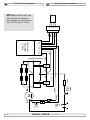
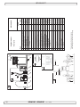
Visual wiring diagram............................................................... 16
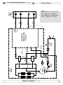
Technical wiring diagram ......................................................... 17
Checklist for control of the installation...................................... 18
User's manual
Important user precautions....................................................... 19
How to use Sidepower thrusters.............................................. 20
Maintenance & service............................................................. 21
Troubleshooting........................................................................ 22
Warranty statement ............................................................... 23
Spareparts list & drawing ..................................................... 24
Service centres ...................................................................... 28
DECLARATION OF CONFORMITY
We, Sleipner Motor AS
P.O. Box 519
N-1612 Fredrikstad, Norway
declare that this product with accompanying
standard remote control systems complies with
the essential health and safety requirements
according to the Directive 89/336/EEC of 23
May 1989 amended by 92/31/EEC and
93/68/EEC.
Innhold
N
Installasjons instruksjoner
Tekniske spesifikasjoner..............................................................3
Planlegning og viktige forbehold.................................................4
Tunnel installasjon
Plassering av tunnel/thruster.......................................................5
Utforming av tunnelåpninger.......................................................6
Hvordan unngå turbulens rundt tunnelåpninger..........................7
Forslag til tunnelinstallasjon på seilbåt........................................8
Tunnel installasjon i glassfiberbåter............................................9
Thruster installasjon
Gearhus og motorbraket...........................................................11
Oljebeholder og propeller..........................................................12
Elektromotor..............................................................................13
Elektrisk installasjon..................................................................14
Kontrollpanel og kontrollkabler..................................................15
Koblingsskjema elektrisk...........................................................16
Koblingsskjema.........................................................................17
Sjekkpunktliste for kontroll av installasjon.................................18
Brukermanual
Viktige forbehold........................................................................19
Hvordan operere Sidepower thrustere......................................20
Vedlikehold og servise...............................................................21
Problemer og løsninger.............................................................22
Garantierklæring ....................................................................23
Reservedelsliste .....................................................................24
Servicesentere ....................................................................... 28
Samsvars erklæring
Sleipner Motor AS
Postboks 519
N-1612 Fredrikstad, Norge
Erklærer at dette produktet med tilhørende
standard kontrollsystemer er i samsvar med
helse, og sikkerhetskravene i henhold til Direktiv 89/336/EEC FRA 23 Mai 89, korrigert av
92/31/EEC og 93/68/EEC.
SE120/215T - SE150/215T
1.0.0- 2007
Waterline
C
A
F
SP 75 Ti SP 95 Ti SP 125 Ti
SE 120/215 TSE 150/215 T
METRIC
METRIC
GB
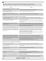
Technical
GB
Technicalspecifications
specifications
Motor:
Custom made reversible DC-motor.
Motor:
Custom made reversible DC-motor.
Gearhouse:
Seawater resistant bronze. Ballbearing at
Gearhouse:
Seawater resistant bronze. Ballbearing at
propellershaft and combination of ballbearing
propellershaft and combination of ballbearing
and slide bearing at driveshaft.
and slide bearing at driveshaft.
Motor bracket: SP 75 Ti / SP 95 Ti / SP 125 Ti:
Motor bracket:
Seawaterresistantaluminium
aluminium,
Seawaterresistant
galvanicly insulated from motor
Tunnel:
Cross spun with rowing G.R.P tunnel
Tunnel:
Cross
spun with tunnels
rowing G.R.P
tunnel
Steel
& aluminum
available
at request.
Steel & aluminum tunnels available at request.
Propeller:
Symmetrical 4 blade propeller, fibreglass reinforced
Propeller:
5-blade skewback "Q-prop" propeller, fibreglass
composite.
reinforced composite.
Batteries:
Minimum recommended battery capacity
Batteries:
Minimum
recommended
battery
capacity
(cold
crank capacity
by DIN/SAE
standard)
(cold crank
by DIN/1045
DIN/SAE CCA
standard)
SP75Ti
12Vcapacity
: 550 CCA
SAE
24V : 300 CCA DIN/570 CCA SAE
SE120/215T 24V : 400 CCA DIN/760 CCA SAE
SP95Ti 12V : 750 CCA DIN/1425 CCA SAE
SE150/215T 24V : 560 CCA DIN/1065 CCA SAE
24V : 400 CCA DIN/760 CCA SAE
SP125Ti 12V : 750 CCA DIN/1425 CCA SAE
400
CCA7-10%
DIN/760
CCA
Max. use:
S2 = 3 24V
min. :or
appr.
within
a SAE
limited time
frame.
Max. use:
S2 = 3 min. or appr. 7-10% within a limited time
Safety:
Safety:
frame.
Electronic time-lapse device protects against
sudden change of drive direction. Electric thermal
Electronic time-lapse device protects against
cut-off switch in electromotor protects against
sudden change of drive direction. Electric thermal
over switch
heatingin(auto
reset when
electroagainst
motor cools
cut-off
electromotor
protects
over
down).(auto reset when electro motor cools down).
heating
Flexible
coupling
between
electro-motor
and
Flexible
coupling
between
electro-motor
and
driveshaft
protects
electromotor
and
gearsystem
driveshaft protects electromotor and gearsystem
if propeller gets jammed.
if propeller gets jammed.
If original Sidepower panel is used, the panel
If original Sidepower panel is used, the panel
shuts
automatically
6 minutes
after
last
use.
shuts
offoff
automatically
6 minutes
after
last
use.
Integratedmicroprocessor
microprocessormonitors
monitorssolenoids,
solenoids,
Integrated
reducing
wear
and
risk
solenoid
lock-in.
Autoreducing
wear
and
risk
of of
solenoid
lock-in.
Autostop
of
thruster
in
case
of
accidental
solenoid
stop of thruster in case of accidental solenoid
lock-in or if run signal is continous for more than
lock-in or if run signal is continous for more than
3 minutes
3 minutes
4
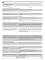
SP 75 Ti SP 95 Ti SP 125 Ti
SE 120/215 TSE 150/215 T
Thrust [lbs]
165
209
275
Thrust [lbs]
242
330
A [in]
7,28
7,28
9,84
A [in]
8,46
8,46
B [in]
13,9
15,3
15,7
B [in]
15,3
15,7
Cmin. [in]
7,87
7,87
9,0
Cmin. [in]
8,5
8,5
D [in]
6,7
6,7
11,0
D [in]
11
11
D recommended [in] 13,4
13,4
22,0
D recommended [in]
22
22
Emin. [in]
0,24
0,24
0,28
Emin. [in]
0,24
0,24
Emax. [in]
0,31
0,31
0,39
Emax. [in]
0,31
0,31
Motor output [Hp]
6
8
8,7
Motor output [Hp]
8,55
11,77
Voltage [V]
12/24
12/24
12/24
Voltage [V]
24
24
Weight [lbs]
44
68
77
Weight [lbs]
74
79
Gear oil capacity [fl.oz]2.367
2.367
6,736
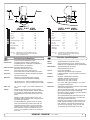
Note: Emin.: wall thickness of a standard Sidepower tunnel
Note:
Emin.:maximum
wall thickness
of a standard
Sidepower
tunnelGRP,
Emax.:
wall thickness
when
using other
Emax.:steel
maximum
wall thickness
or aluminium
tunnelswhen using other GRP,
steel or aluminium tunnels
IMPERIAL
IMPERIAL
Thrust [kg]
75
95
125
Thrust [kg]
120
150
A [mm]
185
185
250
A [mm]
215
215
B [mm]
352
389
398
B [mm]
389
398
Cmin. [mm]
200
200
230
Cmin. [mm]
215
215
D [mm]
170
170
280
D [mm]
280
280
D recommended [mm] 340
340
560
D recommended [mm] 560
560
Emin. [mm]
6
6
7
Emin. [mm]
6
6
Emax. [mm]
8
8
10
Emax. [mm]
8
8
Motor output [kW]
4,4
6
6,5
Motor output [kW]
6,4
8,8
Voltage [V]
12/24
12/24
12/24
Voltage [V]
24
24
Weight [kg]
20
31
37
Weight [kg]
34
38
Gear oil capacity [ml]
70
70
200
Note: Emin.: wall thickness of a standard Sidepower tunnel
Note:
Emin.:maximum
wall thickness
of a standard
Sidepower
tunnelGRP,
Emax.:
wall thickness
when
using other
Emax.:
maximum
wall thickness
steel
or aluminium
tunnelswhen using other GRP,
steel or aluminium tunnels
D
N
Motor:
Motor:
Getriebegeh.:
Technische
Daten
Tekniske
spesifikasjoner
Gleichstrommotor
Spesialutviklet reversibel
DC-motor.
Seewasserbeständige
Bronze.
Kugellager an
der Sjøvannsbestandig
Propellerachse, Kombination
von KugelGirhus:
bronsje. Kulelagre
på proundpellaksel.
GleitlagerKule
an der
Antriebsachse.
og glidelager
komb. på drivaksel.
Motorhalterung:
75 Ti / SP 95 Ti / SP aluminium.
125 Ti:
Motorbraket:SP Sjøvannsbestandig
Seewasserbeständiges
Aluminium
Galvanisk isolert fra motor
Tunnel:
Glasfibertunnel
(Kreuzgewebe)
Tunnel:
Kryssvevet glassfiber.
Stahl& Aluminiumtunnel
aufpåAnfrage.
Aluminium
og ståltunnel
forespørsel.
Propeller:
Symmetrischer,
4 flügeliger
Kaplanpropeller
aus
Propell:
5-blads skewback
"Q-prop"
propell i komposittGlasfiberverbundmaterial.
materiale.
Batterie:
Batteriekapazität
Batterier: Empfohlene
Minimum mind.
anbefalt
batteri størrelse.
(Kaltstartkapazität
nach etter
DIN/SAE)
(Kaldstart kapasitet
DIN std.)
SP75Ti
12V : 550
CCA
SE120/215T
24V:
400DIN/1045
CCA DINCCA SAE
24V : 300
CCA
CCA SAE
SE150/215T
24V:
560DIN/570
CCA DIN
SP95Ti 12V : 750 CCA DIN/1425 CCA SAE
Drift tid:
S2 = 324V
min.: Eller
gjennomsnittlig
7-10%
400 CCA
DIN/760 CCA
SAE innen
en begrenset
tidsperiode.
SP125Ti
12V : 750
CCA DIN/1425 CCA SAE
24V : tidsforsinkelse
400 CCA DIN/760
CCA SAE
Sikkerhet:
Elektronisk
forhindrer
motorskade
ved
rask
retningsendring.
Betriebszeit:
S2 = 3 min. oder ca. 7-10% innerhalb eines
MotorenZeitraumes.
stanser automatisk ved overopphetning
beliebigen
(slår seg automatisk på etter nedkjøling).
Sicherheit:
Elektronische Zeitverzögerung zum Schutz des
Brytepinne
mellom drivaksel
og motor
beskytter
Getriebes
bei plötzlichem
Wechsel
der DrehrichgirElektrischer
hvis propellThermoschalter
blir blokkert. zum Schutz
tung.
desOm
Motors
gegen
Überhitzung
(erneute
Betriebs
orginalt
Side-Power
panel
blir brukt
så vil
bereitschaft
Abkühlung).
dette slåsnach
av automatisk
etter 6 minutter etter
siste gang
trøsteren
ble brukt.und GetriebeScherstift
zwischen
Elektromotor
achse
als
Schutz,
wenn
der Propeller
blockiert
Integrerte microprossessor
føler hele
tiden på ist. releet,
Nach der
letzten Benutzung
schaltet
das på reduserer
slitasje og risk
for ”heng”
Original
Side-Power
6 relé. Trøsteren
vilPanel
stoppeautomatisch
automatisk nach
etter 3
Minuten
ab. om
Derdet
integrierte
minutter
oppstår Mikroprozessor
”heng” på relé, eller überwacht
das Relais
und reduziert
sowohl
om trøsteren
går kontinuerlig
i 3 minutter.
Verschleiß, als auch Relaisblockade. Das
Bustrahlruder stoppt automatisch bei RelaisBlockade, oder bei Betrieb des Bugstrahlruders
von mehr als 3 Minuten.
SP 75
Ti / SP 95 Ti
/ SP 125 Ti
SE120/215T
- SE150/215T
2.5.1- 2007
2007
1.0.0-
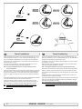
Planning and important precautions
GB
Prior to installation, it is important that the installer reads this guide to ensure necessary acquaintance with this product.
The thruster must NOT be installed in compartments that require ignition proof electric equipment. If necessary, make a separate
compartment.
The electromotor will generate some carbon dust so that any storage compartment must be separated from the thruster to prevent the stored items
from becoming dusty/dirty.
If you are installing the Sidepower in a small room /compartment, it should be ventilated to ensure cooling of the electromotor.
If the height in the room you are installing the Sidepower is limited, the Sidepower can be installed horizontally or at any angle in between.
-
If the electro motor is positioned more than 30o off vertical, it must be supported separately.
-
The electromotor must be handled carefully. Do not lift it by the internal connections/main terminals or put it down on the driveshaft.
-
Beware to keep installation within advised measurements. No part of the propeller or gearhouse must be outside the tunnel.
The electromotor, its components, contacts / plugs or other joints in the control cables must be mounted so that they will keep dry at all times.
We advice to paint the gearhouse and propellers with antifouling. PS! Do not paint the zinc anodes, sealings or propellershafts.
Do not finish the inside of the tunnel with a layer of gelcoat / topcoat or similar. It is only room for a thin layer of primer and two layers of
anti-fouling between the tunnel and the props.
With the boat on land, only run the thruster for a fraction of a second, as without resistance it will accelerate very fast to a damaging rpm.
Also, while the thruster is in air, make sure that the propellers have come to a complete stop before performing a directions change of the
thruster, as it might cause damage to the thruster.
This manual is intended to support educated/experienced staff and is therefore not sufficient in all details for the correct installation.
Don’t install the electromotor at close range to easily flammable objects as it will reach over 100°C before the temperature switch is
activated.
Do not store items close to the thruster motor as it gets hot as well as any loose items near the thruster motor can cause problems with electrical wiring coming loose and short-circuiting.
When installed in boats approved or classified according to international or special national rules, the installer is responsible for following the demands
in accordance with these regulations / classification rules. The instructions in this guide can not be guaranteed to comply with all
different regulations/classification rules.
These instructions are only general instruction. If you are not skilled to do this work, please contact professional installers for assistance.
NB! Faulty installation of the tunnel, thruster or panel will render all warranty given by Sleipner Motor AS void.
Viktige forholdsregler og planlegning
N
Før installasjon må instruksjonsmanualen leses gjennom, og bruker må gjøre seg kjent med produktet.
Thrusteren må ikke installeres i rom som der gnister og høy varme medfører brannfare.
Elektromotoren vil produsere karbon støv fra børstene under drift slik att en lagringsplass må fysisk avskilles fra thrusteren for å unngå att det man
lagrer blir støvete / møkkete.
Elektromotoren er avhengig av god kjøling, sørg derfor for ventilasjon eller god plass rundt motoren ved montering.
Elektromotoren kan monteres i alle vinkeler i fra vertikalt til horisontalt der hvor plassutnyttelsen krever det.
Hvis elektromotoren monteres i en vinkel på mer en 30o, må den støttes opp separat.
Elektromotoren må håndteres forsiktig. Den må ikke bæres etter kontaktpunktene, og motoren må ikke settes ned på drivakselen.
Følg de anbefalte målene som er oppgitt i manualen, propell eller girhus må ikke stikke ut av tunnelen.
Elektromotoren, tilhørende komponenter, kontakter eller åpne ledd i strømkabler må monteres så de ikke utsettes for vann.
Vi anbefaler å male girhuset med bunnstoff. PS sinkanoder, pakninger og propellaksel skal ikke påføres bunnstoff.
Ikke påfør gelcoat / topcoat eller lignende inne i tunellen. Det er bare plasee til ett lag primer og to lag bunnstoff mellom tunellen og propellene.
Når båten ligger på land har ikke elektromotoren den motstanden den har i vann. Motoren bruker derfor ekstremt kort tid før den oppnår ødeleggende
høyt turtall. Med båten på land, unngå hurtig bytte av driftsretning da det kan forårsake skade på truster.
Denne manualen er beregnet som støttemateriell for montører med erfaring / utdanning, og har derfor ikke all informasjon nødvendig for å oppnå en
korrekt installasjoner.
Installer ikke elektromotoren i nærheten av lett brennbart materiale, da motoren oppnår temperaturer over 100oC ved før den stopper automatisk.
Området intill thrusteren må ikke benyttes som lagringsplass da motoren vil bli varm samt att dette vil medføre en fare for att elektriske koblinger blir
løse eller kortslutter
I de tilfeller båter skal godkjennes eller klassifiseres i henhold til internasjonal, eller spesielle standarder, er montør ansvarlig for at de gjeldende lover
og regelverk følges. Sleipner Motor AS kan ikke garantere at instruksjonene i denne manualen er i henhold til alle gjeldende regelverk og standarder.
NB ! Ved feilaktig installasjon av panel, thruster eller tunnel frafaller all garanti stilt av Sleipner Motor AS.
SE120/215T - SE150/215T
1.0.0- 2007
Fig. 1
Pivot
point
Fig. 3
A
B
B = 10,0m
A = 11,0m
min.
1/2Ø
Fig. 2
30 - 35 cm*
1/1 Ø
--
3/4Ø
-
Fig. 4
min.
1/3Ø
mi n
1/3 .
Ø
Ø
GB
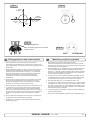
Positioning of the tunnel / thruster
The
bebe
asas
farfar
forward
as possible
(Fig.(Fig.
1) 1)
The Thruster
Thrustershould
should
forward
as possible
Because
around
thethe
boats
pivot
point,
it is it
very
Becauseofofthe
theleverage
leverageeffect
effect
around
boats
pivot
point,
is very
important
actual
effect
in the
boatboat
to get
as itfar
importantfor
forthe
thethrusters
thrusters
actual
effect
in the
to itget
asfor-ward
far foras
possible.
The relative
distancedistance
change from
the from
boatsthe
pivot
pointpivot
to the
ward
as possible.
The relative
change
boats
thruster
the change
of the
actual
thrustof
foractual
the boat.
point to will
thebe
thruster
will be
change
thrust for the boat.
Example:
Example:
A:
= 605kgm
torque
to rotate
the boat
A: 55kg
55kgthrust
thrustxx11m
11mleverage
leverage
= 605kgm
torque
to rotate
the boat
B:
= 550kgm
torque
to rotate
the boat
B: 55kg
55kgthrust
thrustxx10m
10mleverage
leverage
= 550kgm
torque
to rotate
the boat
In
more
thrust
to turn
the the
boatboat
around.
In position
positionAAyou
youwill
willget
get10%
10%
more
thrust
to turn
around.
The
bebe
placed
as as
deep
as possible
(Fig. (Fig.
2)
The thruster
thrustershould
should
placed
deep
as possible
2)
The
asas
deep
as as
possible
for two
reasons:
The tunnel
tunnelshould
shouldbebeplaced
placed
deep
possible
for two
reasons:
1.
down
air air
from
the the
surface
which
will will
1. So
So that
thatititdoes
doesnot
notsuck
suck
down
from
surface
which
destroy
destroythe
thethrust
thrustcompletely.
completely.
2.
a water
pressure
to get
maximum
2. To
To get
getas
ashigh
highasaspossible
possible
a water
pressure
to get
maximum
efficiency
efficiencyfrom
fromthe
thepropeller.
propeller.
Generally
tunnel
should
be be
a minimum
of ½of
x the
Generallythe
thetop
topofofthe
the
tunnel
should
a minimum
½ xtunnel
the
diameter
below the
waterline.
This is anThis
absolute
we rectunnel diameter
below
the waterline.
is anminimum
absoluteand
minimum
ommend
that it is at least
diameter
() below
the waterline.
and we recommend
that¾itxistunnel
at least
¾ x tunnel
diameter
(-) below
A
really
good distance
aboutdistance
1/1 x tunnel
diameter
below
the
the
waterline.
A reallyisgood
is about
1/1 x()
tunnel
diameter
waterline.
(--) below the waterline.
When
tunnel
30-35
cm*/1
feetfeet
below
the surface,
Whenyou
youget
getthe
thetop
topofofthe
the
tunnel
30-35
cm*/1
below
the
other
factors
should
be should
considered
more important,
moving the
surface,
other
factors
be considered
morei.e.
important,
i.e.thruster
furtherthe
forward.
moving
thruster further forward.
Optimal
Optimaltunnel
tunnellength
length
If the
the
friction
inside
willwill
reduce
the water
speed
the tunnel
tunnelgets
getstotolong,
long,
the
friction
inside
reduce
the water
and
thereby
the thrust.
speed
and thereby
the thrust.
If the
(normally
only
in the
bottom
section
of theoftunthe tunnel
tunnelgets
getstotoshort
short
(normally
only
in the
bottom
section
the
nel)
you you
can can
get cavitation
problems
as theas
water
notwill
have
time to
tunnel)
get cavitation
problems
the will
water
nothad
have
“straighten”
before reaching
the propeller
This (Fig.
cavitation
had time toitself
“straighten”
itself before
reaching(Fig.
the3&4).
propeller
3&4).
will
performance
as well
as creatingas
a lot
of as
noise.
Thisreduce
cavitation
will reduce
performance
well
creating a lot of
The
optimal tunnel length is 2 to 4 x tunnel diameter and you should avoid
noise.
tunnels
longertunnel
than 6length
to 7 times
diameter
as the
performance
The optimal
is 2 the
to 4tunnel
x tunnel
diameter
and
you should
reduction
is then
clearly
noticeable.
avoid tunnels
longer
than
6 to 7 times the tunnel diameter as the
performance reduction is then clearly noticeable.
10
N
D
Positionierung
Tunnel
/ Thruster
Plassering avvon
tunnel
og thruster
Tunnelen
bør plasseres
lengst
mulig
frem
i baugen
(Fig.
Tunnelplazierung
soweit
vorne
wie
möglich
(Fig.
1) 1)
For
oppnå
mest mulig
moment
rundt vom
båtens
dreiepunkt,
det meget
Um åeinen
möglichst
großen
Abstand
Drehpunkt
deserSchiffes
zu
viktig
å plassere
tunnelen
så langt
fremmeweit
somvorne
mulig.einzubauen.
Avstanden fra
erreichen,
ist der
Sidepower
möglichst
båtens
dreiepunkt til thruster
vil ha stor vom
betydning
på thrusterens
effekt.
Eine Vergrößerung
des Abstandes
Drehpunkt
des Schiffes
hat eine direkte Auswirkung auf die verfügbare Schubkraft.
Eks.:
A:
55kg skyvekraft
x 11m moment = 605kgm skyvekraft
Beispiel
:
B:
x x 10m
= 550kgm
skyvekraftdes Bootes
A: 55kg
55kgskyvekraft
Schubkraft
11mmoment
= 605kgm
zum Wenden
Posisjon
vil gi 10% mer
skyvekraft
til rotasjon.
B: 55kg A
Schubkraft
x 10m
= 550kgm
zum Wenden des Bootes
In Beispiel A stehen damit 10% mehr Schubkraft zur Verfügung.
Tunnelen skal plasseres dypest mulig (Fig. 2)
Tunnelen
skal so
plasseres
såmöglich
dypt sompositionieren
mulig av to grunner:
Den Tunnel
tief wie
(Fig. 2)
1.
SåTunnel
luft ikkeaus
suges
ned
i tunnelen
ødelegger
skyvekraften.
Den
zwei
Gründen
soå tief
wie möglich
positionieren:
2.
Ved å øke
vanntrykket
jobber propellen
merdie
effektivt.
1. Damit
nicht
Luft mitangesaugt
wird, die
Schubkraft
Hovedregelen
at tunnelen skal plasseres minimum ½ x tunnelen dia.
vollständigerherabsetzt.
under
Anbefalt dybde
minst ¾ x dia.zu
under
vannlinje
2. Umvannlinje.
einen möglichst
hohenerWasserdruck
erhalten,
um().
die Når
tunnelen
er plassert
33-35
cmPropellers
under vannlinjen
bør andre faktorer vurmaximale
Effizienz
des
erreichen.
deres
som viktigere,
å plassere
tunnelen
lengre
frem.TunnelDie Oberkante
desd.v.s.
Tunnels
muß mind.
einen
halben
durchmesser unterhalb der Wasserlinie liegen. Dieser Wert ist ein
Optimal
tunnel
lengdeBesser ist ein Wert von ca. ¾ des
absolutes
Minimum.
Dersom
tunellen blir for(-).
lang Optimal
vil friksjonen
i tunellen
reduser
Tunneldurchmessers
ist eine
Abstand
vonvannhastig1/1 x
heten
og derved effekten.
Tunneldurchmesser
(--) zur Wasserlinie.
Dersom
blir fordes
kortTunnels
(normalt30-35cm*
bare i nedre
del avunterhalb
tunellen) kan
Liegt dietunellen
Oberkante
/ 1fuß
der det
oppstå
kavitasjons
problemer
vannet ikke
har tid / av-stand
til å «rette
Wasserlinie,
können
anderedaFaktoren
berücksichtigt
werden.
opp strømningsretningen» før det treffer propellen (Fig. 3&4). Denne
kavitasjonen
vil redusere effekten og lage mye støy.
Optimale Tunnellänge
Den
optimale
lengden
er 2reduziert
til 4 ganger
tunell
diameteren og die
dersom
Bei einem
zutunell
langem
Tunnel
der
Reibungsverlust
tunellen
blir så mye som 6 und
til 7 ganger
diameteren
i lengde vil effekt tapet
Wassergeschwindigkeit
damit die
Schubkraft.
bli
merkbart.
Beiklart
einem
zu kurzem Tunnel (häufig im unteren Bereich des
Tunnels) können Kavitationsprobleme entstehen, da sich das
Wasser nicht gerade auszurichten kann (Fig. 3&4). Diese Kavitation ist leistungsreduzierend und kann starken Lärm verursachen.
Die optim. Tunnellänge ist das 2-4 fache des Tunneldurchmessers.
Tunnellängen von mehr als dem 6-7 fachen des Tunneldurchmessers sollten vermieden werden, da dadurch die Leistung
reduziert wird.
- Ti
SE150/215T
SPSE120/215T
75 Ti / SP 95
/ SP 125 Ti
1.0.02007
2.5.12007
Fig. 2
Fig. 1
R = 0,1 x D (10%)
D
R = 0,1 x D (10%)
/
Fig. 4
Fig. 3
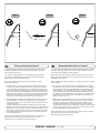
GB
Tunnel ends
Formgebung
der Tunnelenden
Tunnelåpninger
N
D
Rounded tunnel
ends
will maximize
thrust and
minimize
Rounded
tunnel
ends
will maximize
thrust
and noise.
minimize
noise.
Avrundede åpninger
vil minke støy,
og maksimere
effekt.
Abgerundete
Tunnelenden
erhöhen
die Schubkraft
und
reduzieren das Geräuschniveau.
much
as possible.rounding the tunnel connection to the hull-side as
We
recommend
The optimum
rounding has a radius of 10% of the tunnels diameter.
much
as possible.
The optimum rounding has a radius of 10% of the tunnels diameter.
Den Bereich
optimale Tunnelende
avrundingen har
en radie som
er Rumpfes
10% av tunnelens
diamDer
/ Außenseite
des
ist soweit
eter.
möglich
abzurunden. Der optimale Wert für den Radius dieser
Rundung beträgt 10% des Tunneldurchmessers.
Important advantages over sharp tunnel to hull connections are:
Vorteile gegenüber einer scharfen Tunnel / Rumpfverbindung sind:
The
cavitation
that tunnel
will come
sharp tunnel
endofwhen
water
1.
rounded
endfrom
will aprevent
creation
turbulence
cavitation
passes by fast,
thereby
preventing
a double
negative
impact
on
that will
come
from a sharp
tunnel
end when
water
passes
the thrustbyand
noise
level preventing
(Fig. 1 & 2).a double negative impact on
fast,
thereby
the
- The
turbulence
/ cavitation
blocks
thrust
and noise
level (Fig.
1 &the
2). outer area of the tunnel
- The
and thereby
reduces
the effective
tunnel
diameter
and
turbulence
/ cavitation
blocks
the outer
area
of thrust.
the tunnel
- and
The turbulence
/ cavitation
hits the propeller
and thereby
thereby reduces
the effective
tunnel diameter
andreduce
thrust.
- The
the propellers
performance
noise. and thereby reduce
turbulence
/ cavitationand
hitscreates
the propeller
the propellers performance and creates noise.
tasjon, noe somTunnelenden
vil oppstå vedverhindern
en installasjon
med skarpe/ kanter.
1. Abgerundete
Turbulenzen
Kavitation,
Turbulensen
forårsaker mer støy,
og begrenserauftreten.
skyvekraften.
wie
sie an scharfenkantigen
Tunnelenden
Damit
werden
- Turbulensen
kavitasjonen
blokkerer tunnelen
og svekker
skyvekrafzwei /negative
Auswirkungen
auf Schubkraft
und
ten.
Geräuschentwicklung
vermieden (Fig. 1 & 2).
- ITurbulenz
det kavitasjon
og turbulens
når propellen
påvirkes ytelsen
til denne
/ Kavitation
blockieren
den äußeren
Tunnelbereich.
og øker støyen.
Dadurch
werden effektiver Tunneldurchmesser und Schubkraft reduziert.
2. -En
avrundet
tunnelåpning
gjør trifft
ogsåauf
at thrusteren
sugerund
vannreduziert
langs
Die
Turbulenz
/ Kavitation
den Propeller
skroget
påEffektivität
båten. Dermed
et lavtrykk
som vil hjelpe å suge
dessen
und oppstår
führt zudet
zusätzl.
Geräuschentwicklung.
We recommend rounding the tunnel connection to the hull-side as
Important advantages over sharp tunnel to hull connections are:
1. The rounded tunnel end will prevent creation of turbulence
2. The curved tunnel end makes the thruster take water also from
The
alongcurved
the hull-side,
a vacuum
that willtake
suckwater
the boat
2.
tunnel creating
end makes
the thruster
also from
along
sideways
therebycreating
give additional
thrust
(Fig.
& 4). the boat
theand
hull-side,
a vacuum
that
will3suck
sideways
With a sharp
tunnel
end,give
the thruster
will thrust
be unable
and
thereby
additional
(Fig.to3take
& 4).water
With
from along
thetunnel
hull-side,
and
you
will notwill
getbe
theunable
desiredtovacuum
a sharp
end,
the
thruster
take water
from
and additional
This and
“free”you
additional
can
in optimal
along thethrust.
hull-side,
will notthrust
get the
desired
vacuum
and
installations
be as
muchThis
as 30
- 40%
of the total
thrust.
additional
thrust.
“free”
additional
thrust
can in optimal
installations be as much as 30 - 40% of the total thrust.
NB! A Sidepower thruster propeller does not cavitate at working
A
speed
so that all
cavitation
and cavitation
in the
will
NB!
Sidepower
thruster
propeller
does notnoise
cavitate
at tunnel
working
speed
be caused
by the
installation.
so that
all tunnel
cavitation
and cavitation noise in the tunnel will
NB! be
Even
if it is not
possible
to installation.
make the perfect rounding, it is very
caused
by the
tunnel
Even
important
to not
round
the tunnel
end asthe
much
as possible.
A it is very
NB!
if it is
possible
to make
perfect
rounding,
important
angled tunnel
to hull the
connection
will also
do much
of the same
to round
tunnel end
as much
as possible.
A
angled
job as a tunnel
rounded
(see page
20, Fig.
1b & 1d).
toconnection
hull connection
will also
do much
of the same
job as a rounded connection (see page 20, Fig. 1b & 1d).
12
Vi anbefaler å avrunde tunnelåpningene mest mulig.
Hvorfor er en avrundet tunnelåpning så viktig?
1. En avrundet tunnelåpning vil forhindre at det oppstår turbulens / kavi-
båten i dreieretningen. Med skarpe åpninger klarer ikke thrusteren å
suge vann langsermöglichen,
skroget, og lavtrykket
uteblir.entlang
Så myeder
somRumpf40% av
2. Abrundungen
daß Wasser
skyvekraften angesaugt
har blitt måltwerden
til å liggekann.
her på
noen installasjoner.
außenseite
Dadurch
entsteht ein
Vakuum ("zusätzliche" Schubkraft"), das das Schiff seitwärts
NB!
Propellene
Sidepower
thrustere kaviterer
ikke på
arbeids-hasbewegt
(Fig. til
3&
4). Bei scharfkantigen
Enden
kann
kein
tighet, entlang
så kavitasjon
og støy som oppstårangesaugt
som følge av
kavitasjon,
Wasser
der Rumpfaußenseite
werden,
skapes das
av tunnel
installasjonen.
wodurch
benötigte
Vakuum nicht zustande kommt.
NB!
SelvSchubkraft
der en perfekt
avrunding
ikke er mulig
er det viktig
av
Diese
kann
bei optimaler
Installation
bis zuå runde
30-40%
så mye
som mulig,
en tunnelåpning med skråkant vil ha
derkantene
absoluten
Schubkraft
betragen.
NB !
stor effekt fremfor en med skarpkant (se side 20, ill. 1b & 1d).
NB !
SE150/215T
SPSE120/215T
75 Ti / SP 95- Ti
/ SP 125 Ti
Sidepower Propeller sind so ausgelegt, daß sie nicht
kavitieren, sodaß die Geräuschentwicklung aufgrund von
Kavitation durch die Tunnelinstallation bedingt ist.
Ist eine optimale Abrundung nicht möglich, so sind die
Tunnelenden soweit möglich abzurunden. Angeschrägte
Tunnel / Rumpfverbindungen sind zu einem gewissen Grad
ebenfalls mit ähnlich positiven Auswirkungen wie eine
Abrundung verbunden (siehe Seite 20, Fig. 1b & 1d).
1.0.02007
2.5.12007
Fig. 1
/
GB
Fig. 2
Fig. 3
-
-
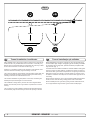
Prevent drag from tunnel
D
N
Optimaler
Strömungsverlauf
am Rumpf
Motstand
forårsaket av tunnel
A
in in
sailboats
or fast
powerboats
is that
A possible
possibleproblem
problem
sailboats
or fast
powerboats
is they
that get
theya get a
drag
ofof
thethe
tunnel,
as as
thisthis
becomes
a “flat”
area area
drag from
fromthe
theback
backface
face
tunnel,
becomes
a “flat”
facing
facingthe
thewater
waterflow
flow(Fig.
(Fig.1).1).
Et
mulig problem
seilbåter
ellerBooten
meget hurtiggående
båter er motstand
Segelboote
undfor
sehr
schnelle
können gelegentlich
durch
iauf
tunnelen.
Aktre endeFläche
på tunnelen
vil være auftreffendes
en liten loddrettWasser
flate mot
die rückseitige
des Tunnels
vannstrømmen
som(Fig.
skaper
gebremst werden
1).uønsket motstand.
This
with
thethe
thruster
spinning
(passive)
This can
canalso
alsocreate
createproblems
problems
with
thruster
spinning
(passive)
and
or or
driving
thethe
boat
withwith
water
being
and making
makingnoise
noisewhile
whilesailing
sailing
driving
boat
water
being
pushed
atat
high
speed.
pushedthrough
throughthe
thetunnel
tunnel
high
speed.
Denne
flatendazu
kan også
forårsake
problemer
med atdurch
vann føres
inn i tunDies kann
führen,
daß sich
der Thruster
den permanelen
under
seilas, eller kjøring
i høypassiv
fart ogzu
fårdrehen
da propellen
til å rotere,
nenten
Wasserdurchfluß
hörbar
beginnt.
dette skaper uønsket støy.
This
ways,
depending
on what
is is
This can
canbe
besolved
solvedinintwo
twodifferent
different
ways,
depending
on what
possible
possibleororeasier
easiertotodo.
do.
Det
er to mulige løsninger på problemet, avhengig av hva som er enklest
werden.
å få til på båten.
1.
normally
reduces
the drag
mostmost
is to make
1. The
Thebest
bestsolution
solutionwhich
which
normally
reduces
the drag
is to
a
recess
in the hull
at the
back
of the
tunnel.
Thereby
back face
make
a recess
in the
hull
at the
back
of the
tunnel.the
Thereby
the
is
gone
andisabout
theabout
drag (Fig.
2).drag
The depth
andThe
shape
of this
back
face
goneall
and
all the
(Fig. 2).
depth
and
recess
depend
on the
Basically
should
not seeyou
the back
shape will
of this
recess
will boat.
depend
on theyou
boat.
Basically
face
of the
when
standing
in front
of the
tunnel at
the
should
nottunnel
see the
back
face ofdirectly
the tunnel
when
standing
directly
angle
ofof
the
boats
centreline.
The angle
or down
backwards
in front
the
tunnel
at the angle
of theupboats
centreline.
Theof the
insert
depends
on theofhull
butthe
normally
it is angled
angleinupthe
or hull,
down
backwards
theshape,
insert in
hull, depends
on
slightly
because
of the water
flow on slightly
this areadown
of thebecause
hull.
the hulldown
shape,
but normally
it is angled
of
1. im
DenRumpfbereich
løsningen somhinter
vanligvis
reduserer
mest ervornimmt.
å lage
dem
Tunnel motstanden
eine Aussparung
en fordypning
i skroget
i aktre ende
av störender
tunnelåpningen.
loddrette
Dadurch
werden
Auftreffläche
und
EffektDen
eliminiert
flaten2).
vil da forsvinne og dermed motstanden. Hovedregelen å følge
(Fig.
er at bakkanten
tunnelen
ikke skal synes
når vom
man står
Tiefe
und Formavdieser
Aussparung
hängen
Bootrett
ab.foran
båten
å titter akterover
langs båten
utformingen
Die
Innenseite
des Tunnels
solltesenterlinje.
von vorneDybden,
prinzipiell
nicht
og vinkling
av fordypningen avhenger av båttypen, og hvordan vannet
sichtbar
sein.
følgermögliche
skroget, men
de fleste
båter vil være
tjent en
fordypning
Der
Winkel
der Aussparung
hängt
meist
von dersom
vinkler lett nedover
(Fig. 2).durch die Wasserströmung in diesem
Rumpfform
ab. Bedingt
2. The drag will also be reduced a lot, especially in fast power boats, by
a deflector
spoiler
in front
of the
tunnel. This
will power
push the
2. making
The drag
will also/ be
reduced
a lot,
especially
in fast
water
out from athe
hull so that
most in
of front
it passes
by tunnel.
the backThis
face
boats,flow
by making
deflector
/ spoiler
of the
of
tunnel
3).flow out from the hull so that most of it passes
willthe
push
the(Fig.
water
The
shape
and
size
this
deflector
by the
back
face
ofofthe
tunnel
(Fig.will
3).depend on the hull shape.
Basically
youand
should
back face
the tunnel
when
The shape
sizenot
of see
this the
deflector
will of
depend
on the
hullstanding
directly
front of the
at the
of the
boats
The
shape. in
Basically
youtunnel
should
not angle
see the
back
facecentreline.
of the tunnel
easiest
way of making
this
to let
parttunnel
of theat
tunnel
stick out
in the
when standing
directly
in is
front
ofathe
the angle
of the
lower
areaThe
of the
hole, and
as a this
support
a of
boatsforward
centreline.
easiest
wayuse
of this
making
is totoletmould
a part
soft
curve/spoiler
shape.
the tunnel
stick out
in the lower forward area of the hole, and use
2. Motstanden vil også reduseres av en spoiler i forkant av tunnelen.
Spoileren
fører det meste av vannstrømmen
rundt
forbi tunnelen.
2. Der
Geschwindigkeitsverlust
kann speziell
bei og
schnellen
Booten
Størrelsen
og Abweiser
utformingen
på spoileren
avhenger
av båten.
Hovedurch
einen
bzw.
Spoiler vor
dem Tunnel
deutlich
dregelen erwerden.
at bakkanten av tunnelen ikke skal synes når man står
reduziert
rett foran
båtenwird
å titter
akterover langs
senterlinje. Den
enkleste
Das
Wasser
so beeinflußt,
daßbåten
es größtenteils
an der
måten å lage
spoileren
pågeleitet
er å la tunnelen
stikke
frontalen
Fläche
vorbei
wird (Fig.
3). ut i forkant av tunnelen, ogund
forme
spoileren
mot denhängen
(Fig. 3). von der Rumpfform ab.
Form
Größe
des opp
Abweisers
the water flow on this area of the hull.
this as a support to mould a soft curve/spoiler shape.
Remember to still round the tunnel ends as much as possible to get
optimum
thruster
performance
minimum
noise.
Foras
more
Remember
to still
round the and
tunnel
ends as
much
possible to get
information
on howperformance
to practically do
this
see pagenoise.
20. For more
optimum thruster
and
minimum
information on how to practically do this see page 20.
14
Das Problem kann je nach Möglichkeit auf zwei Arten beseitigt
1. Der störende Effekt wird am deutlichsten reduziert, indem man
Bereich sollte dieser Winkel leicht nach unten gerichtet sein.
Prinzipiell sollte auch hier die Innenseite des Tunnels von vorne
Detnicht
er alltid
viktig åsondern
avrunde durch
tunnelåpningene
mestverdeckt
mulig for sein.
å motvirke
sichtbar,
den Abweiser
støyDieser
og for läßt
å få mest
mulig effekt
av thrusteren.
sich einfach
realisieren,
indem man den Tunnel ein
MerStück
informasjon
om Rumpf
dette påherausstehen
side 20.
aus dem
läßt und darauf einen
geschwungenen Abweiser / Spoiler formt.
Die Tunnelenden sind zur vollen Leistung und minimalen
Geräuschentwicklung des Thrusters weitgehend abzurunden.
Weitere Informationen siehe Seite 20.
- Ti
SE150/215T
SPSE120/215T
75 Ti / SP 95
/ SP 125 Ti
1.0.02007
2.5.12007
Fig. 1
-
Pos. A
Pos. B
/
-
Min
/
GB
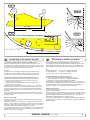
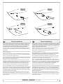
Tunnel installation in sailboats
N
D
Tunnel
installasjon
på seilbåter
Installation
in Segelbooten
Many
racing
type
hullhull
which
means
that that
it is very
flat botManysailboats
sailboatshave
havea a
racing
type
which
means
it is very
tomed
and hasand
a very
in thedraft
bowin
section.
It issection.
therebyItvery
flat bottomed
hasshallow
a verydraft
shallow
the bow
is
difficult
to say
impossible
to fitimpossible
a tunnel thruster
usualthruster
way, at least
therebynot
very
difficult
not to say
to fit athe
tunnel
the
as
far forward
the as
hullfar
as forward
a thruster
(Fig.
1).
usual
way, at in
least
inshould
the hullbeas
a thruster
should be
Mange
seilbåtskrog
byggeteinen
for å oppnå
fart. De har auf,
brede
skrog
Segelboote
weisenerhäufig
Rumpfhøy
in Rennform
was
som
stikker
dypt Rumpf
i baugen.
gjør
det vanskelig
installere
einenikke
sehr
flachen
imSkrogtypen
Bugbereich
bedeutet.
Es istå daher
en
thrustertunnel
på vanlig
måte, spesielt
med tanke
pågewünschten
å plassere den
schwierig
oder fast
unmöglich,
den Tunnel
an der
langt
nok frem Stelle,
(Fig. 1).also möglichst weit vorne im Bug zu plazieren
(effektivsten)
However, it is possible to install a tunnel thruster in most sailboats, even
when
the hull
not directly
support
the fitting
of a in
tunnel.
However,
it isdoes
possible
to install
a tunnel
thruster
most sailboats,
Thrustertunneler kan allikevel installeres i de fleste seilbåter. Dette gjøres
ved
å la en ist
deles
av vielfach
tunnelenmöglich
stikke ut unter
i underkant
avBedingungen
skroget. Tunnelen
Trotzdem
diesen
eineer
sterk
nok til dette,
og thrusteren
blir wenn
plassert
lavTunnel
nok og damit
langt nok
fremme.
Bugschraube
einzubauen,
auch
der
nicht
völlig
This is done by fitting the tunnel halfway into and halfway under-neath the
existing
hull and
then strengthen
and smoothening
the waterunderflow by
This is done
by fitting
the tunnelit halfway
into and halfway
moulding
bulb around
/ underneath
the tunnel.
neath theaexisting
hull and
then strengthen
it and smoothening the
Dette gjøres ved at øvre halvdel av tunnelen støpes inn i skroget, tunnelen
ved å støpe
kul rundt tunnelen
og integriert,
jevne den ut
Derstyrkes
Tunneli underkant
wird zur Hälfte
in denenbestehenden
Rumpf
mest
mulig. Hälfte geht über diesen hinaus. Der Tunnel muß nur
die andere
This will allow installation in good position on the boat, maintaining the
reliability
and space
advantages
of aposition
tunnel thruster.
This will allow
installation
in good
on the boat, maintaining
Denne metoden brukes av noen av de helt største seilbåt-produsentene i
verden,
de viser
til at
den ikke girinutslag
på fart Position
under normal
seilas.
Dies erlaubt
eine
Installation
geeigneter
bei Nutzung
(Fig. 1).
even when the hull does not directly support the fitting of a tunnel.
water flow by moulding a bulb around / underneath the tunnel.
the reliability and space advantages of a tunnel thruster.
This installation is being used by some of the world’s largest sailboat
builders,
and has is
been
proven
give
little of
to the
no speed
loss
for normal
This installation
being
usedtoby
some
world’s
largest
sailboat
cruising.
builders, and has been proven to give little to no speed loss for
normal cruising.
This can also be a good installation method for flat bottomed barges to
avoid
extremely
tunnels
and hugemethod
oval tunnel
openings
in thebarges
hull.
This can
also belong
a good
installation
for flat
bottomed
to avoid extremely long tunnels and huge oval tunnel openings in the
hull.
16
(Fig. 1).
vom ursprünglichen Rumpf umgeben ist.
noch verstärkt und strömungsgünstig abgerundet werden.
der Zuverlässigkeits- und Platzvorteile einer Tunnelschraube.
Denne installasjonen kan også være gunstig for båter med flate bunner,
for
å unngå
ekstremt lange
og store
tunnelåpninger.
Diese
Installationsart
wirdtunneler
von einigen
derovale
weltweit
führenden
Segelboothersteller verwendet und führt meistens nur zu einem
äußerst geringen bzw. gar keinem Geschwindigkeitsverlust.
Diese Bauweise ist auch für Barkassen (z.B. Flußboote) mit
flachem Bug geeignet, um einen zu langen Tunnel und große
ovale Tunnelöffnungen im Rumpf zu vermeiden.
- Ti
SE150/215T
SPSE120/215T
75 Ti / SP 95
/ SP 125 Ti
1.0.02007
2.5.12007
Fig. 1
R
D
Fig. 2
Fig. 3
GB
Tunnel installation
Fig. 4
N
Tunnel installering
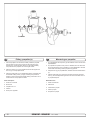
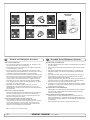
We recommend that a professional does the fibreglass fitting of the
tunnel. These instructions are only general, and do not explain in
any way the details of fibreglass work. Problems caused by faulty
installation of the tunnel, are the installers full responsibility.
Sleipner Motor anbefaler at innstøping av glassfibertunnelen utføres
av kyndig personell. Denne instruksjons manualen gir ikke detaljerte
opplysninger om glassfiberstøpning. Problemer som skyldes installering er installatørens fulle ansvar.
Find the position in the boat considering the information given earlier in
this manual and the applicable measurements for the thruster model you
are installing.
Bestem plassering av tunnelen ut i fra informasjonen gitt tidligere i manualen, og de angitte mål for thrusteren du skal installere.
Mark the centre of the tunnel on both sides. Drill a 6mm hole horizontally
in these marks (Fig. 1).
Bend a ø 5mm steel bar as shown with the “tip” bent back at the tunnel
radius and mark the circle for the tunnel opening (outside diameter of the
tunnel). Cut the hole with a jigsaw (Fig. 2).
Grind off the gelcoat and polyester so that you are down in the “real fibreglass” in an area of 12cm around the hole both inside and outside in the
hull to cast the tunnel to the hull (Fig. 3).
Insert the tunnel and mark its shape to fit the hull (Fig. 4). (if you are installing with a deflector/spoiler, leave a part or the tunnel of the front- and
underside of the tunnel to have a base for this (see page 20, Fig. 2). Cut
the tunnel ends to the desired shape and lightly sand its surface and
clean with acetone or similar where you are going to apply fibreglass.
NB! Do not cast/glass on the area were the thruster will be placed.
Merk av senter på tunnelen på babord og styrbord side. Bor et 6 m.m.
vannrett hull, på begge sider (Fig. 1).
Bøy til og tilpass en 5 m.m. stålstang, som vist på fig. 2 der den tilbakebøyde enden skal markere tunnelens radius. Stikk enden inn å marker
tunnelens ytre diameter, skjær ut hullet med en stikksag (Fig. 2).
Puss av gelcoat og polyester så glassfiberen ligger bar i et 12 cm stort
område rundt tunnel hullet. Dette må gjøres på innsiden og utsiden av
skroget, før tunnelen støpes fast i skroget (Fig. 3).
Sett inn tunnelen å marker hvor det skal kappes for å passe i skroget
(Fig. 4). Hvis det skal støpes en spoiler i forkant av tunnelen bør en del av
tunnelen stikke ut i for og underkant av skroget for å støpe spoileren mot
(Side 20, Fig. 2). Kapp tunnelen i ønsket størrelse. Slip lett med slipepapir, og vask med aceton der hvor det skal støpes med glassfiber.
NB ! Det må ikke støpes der hvor thrusteren skal monteres.
Then cast the tunnel to the inside of the hull, use at least 8 layers of 300 g
glass and resin, preferably alternating mat and rowing types of fibreglass
(see page 20, Fig. 1). If you are rounding the tunnel ends to the perfect
10% radius you may in some cases have to make further layers inside to
preserve the desired hull thickness.
Støp fast tunnelen først på innsiden av skroget, bruk minst 8 lag med 300
g Glassfibermatte, og polyester. Ved bruk av alternative materialer, glassfiber matter eller rovingtyper (Se s. 20, Fig. 1). Hvis tunnelåpningene
avrundes til den optimale 10% radius må ofte legge ekstra lag med polyester glassfibermatte på innersiden av tunnelen, for å oppnå riktig tykkelse i
forhold til skrogtykkelsen.
NB! Make sure that any gap between the tunnel and the hull are completely filled with resin/fibreglass. In areas where you can not access to
make normal layers of resin/fibreglass, a resin/ fibreglass mixture must be
filled in that area.
NB ! Forsikre deg om at overgangene mellom tunel og skrog er nøye
sammenstøpt. På steder en ikke kommer til med vanlige lag med polyester/glassfiber matte, sørg for og lage en blanding av polyester og glassfiber, som fylles i dette.
SE120/215T - SE150/215T
1.0.0- 2007
Fig. 1a
Fig. 1c
Fig. 1b
Fig. 1d
Fig. 1
Fig. 3
Fig. 2
GB
Tunnel installation
N
Tunnel installering
Soften the edges with a radius of 10% of the tunnel diameter (Fig. 1a) or
make a slope with a length of 10-15% of the tunnel diameter (Fig. 1c). If
this is not possible, at least round the tunnel end as much as possible.
Rund av tunnelendene med en radius 10% av tunneldiameter (Fig. 1a),
eller lag en skråkant 10-15% av tunneldiameter (Fig. 1c). Der dette ikke er
mulig skal tunnel kantene rundes av mest mulig.
We advice to also cast two layers on the outside of the tunnel/hull for an
6-8cm area (Fig. 1c & 1d).
Vi anbefaler å støpe to lag utenpå tunnellavrundingen og over et område
på 6-8cm (Fig. 1c & 1d).
You must apply topcoat/epoxy on the areas outside where you have
grounded or moulded to again make these waterproof.
Gelcoat eller lignende må påføres på områdene der det har blitt pusset
eller støpt for å gjøre glassfiberen vanntett.
NB! All original Sidepower tunnels are fully waterproof when
they are delivered.
NB ! Alle originale Sidepower tunneler er vanntette ved levering!
This means that unless you want, because of special reasons, to have another colour on it, you do not have to apply topcoat or the several layers
of primer that is necessary on the boats’ hull to make it water-resistant.
Sand it very lightly and apply one layer of primer to make the antifouling
sit.
The original Sidepower tube itself is fully water-resistant without treatment
except in the areas where you have bonded it to the hull.
Apply topcoat/epoxy paint and primer on the areas where you have
grounded or moulded as these areas give the water access to the hull
which normally is not waterproof without these applications outside.
PS! Avoid all casting where the motor-bracket is to be placed,
as this will cause misfit and possible failure of the
gearhouse.
10
Så fremt man ikke ønsker en annen farge er det ikke nødvendig å påføre
Gelkoat, Topkoat og flere lag med primer for å gjøre tunnelen vanntett.
Puss tunnelen med fint slipepapir og påfør et lag primer for å få bunnstoff
til å sitte.
Sidepowertunnelen er helt vanntett uten behandling med unntak av de
områder det som er støpt fast i skroget.
Påfør Gelcoat/Topcoat/epoxy og primer på de områder som er pusset ned
eller støpt. Vann skal ikke ha direkte kontakt med glassfiberen i skroget
fordi dette normalt ikke er vanntett.
PS ! Det må ikke støpes der brakketen til thrusteren skal stå. Passformen er nøyaktig tilpasset, og en feilplassert braket kan forårsake svikt i girhus.
SE120/215T - SE150/215T
1.0.0- 2007
Fig. 1
BOATS
SP 75 Ti
CENTRELINE
SP 95 Ti
Fig. 2
Fig. 1
SP125Ti
Fig. 3
Fig. 2
SP125Ti
BOATS
BOATS
CENTRELINE
CENTRELINE
Fig. 2
Fig. 3
BOATS
CENTRELINE
TUNNELS
CENTRELINE
TUNNELS
CENTRELINE
Ø 9mm
Ø 32mm
0,35"
1,26"
28,0mm
1,1"
7
TUNNELS
CENTRELINE
Ø 11,00mm
7/16"
Ø 46,00mm
Ø 32mm
1,81"
40,0mm
1,57"
1,26"
Ø 46,00mm
1,81"
40,0mm
1,57"
Fig. 7
Fig. 4
2
1
IL
RO
GEA 90
EP
3
4
Fig. 3
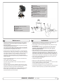
Bolt tightening forces:
Bolts (2x) holding gearhouse to bracket:
SP 75 Ti / SP 95 Ti: 17 Nm (12,4
Bolts lb/ft)
(2x) holding gearhouse to bracket:
SP 125 Ti: 33 Nm (24 lb/ft) SP 75 Ti / SP 95 Ti: 17 Nm (12,4 lb/ft)
SP 125 Ti: 33 Nm (24 lb/ft)
Bolt tightening forces:
PORT
Fig. 7
Bolt tightening forces:
2
Fig. 5
SP 75 Ti
SP STARBOARD
95 Ti
PORT
7
Ø 11,00mm
7/16"
P
Fig. 6
Bolts (2x) holding gearhouse to bracket:
SP125Ti
33 Nm (24 lb/ft)
STARBOARD
PORT
S
Fig. 6
SP125Ti
Fig. 4
P
STARBOARD
PORT
S
P
S
PORT
STARBOARD
STARBOARD
D
and motor bracket
Getriebe und Motorhalterung
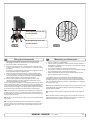
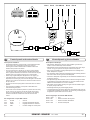
GB Fitting gearhouse and motor bracket
N
Montering
av girhus og brakett
D
Fitting gearhouse and motor bracket
Getriebe
und Motorhalterung
el and the boats centreline. SP75Ti
1. Die Mittellinie von Tunnel und Boot markieren.
1. Marker
båtens og tunnelens senterlinje på tunnelen.
1.
Mark
centrelinelidof(the
the tunnel and
the
centreline.
be
with
the the
gearhouse
SPcentreline.
75 boats
Ti / SP
95 Ti: Damit
und
arkfitted
the centreline
of the tunnel
and the boats
SP75Ti
1.Schubrichtung
Die MittellinieGirhuset
vonKontrollpanel
Tunnel
und Bootmed
markieren.
må plasseres
merket P mot babord og enden
eP95Ti:
propellers)
on
the
starboard
side
of
über-einstimmen,
das
Getriebegehäuse
so
einbauen,
daß der enden
TheThe
gearleg
must
be
fitted
with
the
P-mark
facing
port
and
S-mark
gearhouse must be fitted with the gearhouse lid (the
SP 75 Ti / SPmerket
95 Ti:SDamit
Schubrichtung
und
mot
styrbord (Fig. 4) for
at Kontrollpanel
skyveretning skal korrespondere
to
correspond
with
the
control
panel
Ver-schluß
des
Getriebegehäuses
(der
verschraubte
Verschluß
starboard
(Fig.propellers)
4) for the thrust
direction
to correspond
the crewed in lidfacing
behind
one of the
on the
starboard
side of withüber-einstimmen,
das Getriebegehäuse
so einbauen, daß der
med Steuerbord
merkingen
på
kontrollpanelene.
hinter
einem
der
beiden
Propeller)
Richtung
zeigt
control
panel
e boat for the thrust direction to correspond with the control panel
Ver-schluß des Getriebegehäuses (der verschraubte Verschluß
(Fig. 5).
2. Bruk girhuspakningen for å sjekke målene (7). Thrusteren skal plas5). SP
Ti:
6 holesgasket
oig.mark
the
centre
of
the
and (7) to mark
2. 125
Use
theFig.
gearhouse
the centre
of6the holes andhinter einem der beiden Propeller) Richtung Steuerbord zeigt
SP
125
Ti:
Fig.
seres på styrbord side av senterlinjen med boltehullet i midten av
(Fig.
5).
nts.
Place
the
thruster
in
the
boats
double check
Placeof
the
thruster
the boats
se the gearhouse
gasketthe
(7)measurements.
to mark the centre
the
holes in
and
båten
(Fig. überprüfen!
1). Alle hull må være på båtens eller tunnelens senterlinje
SP
125
Ti:
Fig.
6Maße
2.
Die
Löcher
mit
der
Dichtung
(7)
markieren.
the
centre
(Fig.
1).
It
is
absolutely
centreline
with
the
bolt
hole
as
the
centre
(Fig.
1).
It
is
absolutely
ouble check the measurements. Place the thruster in the boats
for1).
å får
tilder
en presis
installasjon. Dette skyldes at det er meget liten
Den
Thruster
schiffssmittig
plazieren
(Fig.
Da
Abstand
ine
with
the
tunnels’
centreline
to
necessary
are in-line
with
centreline2.
to Die Löcher mit der Dichtung
(7) markieren.
Maße überprüfen!
entreline with
the bolt that
holeallasholes
the centre
(Fig.
1).the
It istunnels’
absolutely
klaring
mellom
tunnelveggen
og propellen.
zwischen
Propellern
wegen größtmöglicher
he clearance
between
theinstallation,
that
ensure
precise
thetunnels’
clearance
between
the und Tunnel
Den Thruster
schiffssmittig plazieren (Fig. 1). Da der Abstand
ecessary
all
holes
are
in-line withasthe
centreline
to
Performance
minimal
ist, 3.
müssen
für må
eine
präzise
nimal
ensure
best possible
Tunnelen
haTunnel
en jevnwegen
overflategrößtmöglicher
der braketen skal festes, all støp,
propellers
and the
is minimal
to ensure
best
possiblekonstruiert
zwischen
Propellern
und
nsureto
precise
installation,
as tunnel
the clearance
between
the
Installation
alle Löcher auf der
Tunnelmittellinie
liegen.
evt
glassfiber
eller epoxyist,
rester
må pusses
ned präzise
så braketen passer
performance.
Performance
minimal
konstruiert
müssen
für eine
opellers and
the tunnel is minimal to ensure
best possible
jevnt
på tunnelen.
Ujevnheter
her vil resultere
i svikt i girhuset.
Löcher
der
Tunnelmittellinie
liegen.
erformance.
3. the
Immotor
Bereich
der is
Motorhalterung
darf keinalle
Laminat
aufauf
dem
e the motor
bracket
isbe
to no
be casting
placed,where
3. There
must
bracket
to be placed,Installation
Tunnel
diesmotor
zu 3.
einem
Getriebeschaden
führenØkann.
e of the
motor
4. der
Bor Motorhalterung
senterhullet
46darf
mm,kein
og deLaminat
to boltehullene
Ø 11 mm
gearhouse.
as no
thiscasting
willThe
cause
possible
failure bracket
of
the gearhouse.
The
Im Bereich
auf dem
here
must
be
where
the motor
issein,
to beda
placed,
Liegt
die
Motorhalterung
nicht
eben sein,
auf dem
Tunnel
auf,
so Getriebeschaden führen kann.
if the
tunnel
is not
smooth,
bracket
must
fitfailure
steadyofon
thegearhouse.
tunnel,
if the
tunnel
is not smooth,
Tunnel
da
dies
zu
einem
sunnel,
this will
cause
possible
the
The
motor
5. Prøv girhuset i tunnelen sammen med pakning 1m.m. Monter propell
sind
sämtliche
UnebenheitenLiegt
in diesem
Bereich abzuschleifen.
tacket
be grinded
smooth.
allfit
bumps
uneven
parts must
grinded
smooth.
die Motorhalterung
ebenav
auftunnelen.
dem Tunnel
auf, so ikke er i midten
must
steadyoron
the tunnel,
if thebe
tunnel
is not
smooth,
å sjekk at den nicht
er i midten
Hvis propellen
sind
sämtliche
Unebenheiten
diesem
abzuschleifen.
l bumps
or
uneven
parts
must
be
grinded
smooth.
4.
Bohren
Sie
das
Zentrumsloch
(ø
32
mm)
dann forsøk
die inå bruk
nd
then the
two
screw-holes
ø
9mm.
avund
tunnelen,
den Bereich
endre pakningen,
eller begge to sam4. Drill the centre-hole ø 46mm and then the two screw-holes ø 11mm.
beiden
Schraubenlöcher
(ø Bohren
9 mm). Sie das
tidig.Zentrumsloch
Hvis tunnelen ikke
harmm)
en jevn
overflate
så kan et tetningsmate4.
(ø 32
und
dann die
rill
centre-hole
ø 32mm
and
then
the(without
two
screw-holes
ø 9mm.
oilthe
type
EP90
through
the oil
5
Try the
lower-unit
in drain
the
tunnel
the zinc anodes
and the
rialedurch
brukesdie
for(ø
å sikre
mot lekkasje.
beiden Schraubenlöcher
9 mm).
5. Das
Getriebegehäuse
EP90
Öffnung
copper
lower(3)
parton
ofagain.
the
flexible
coupling)
by
using
the
insidemit
theGetriebeöl
re-fill
thegasket
gearhouse
with
gear
oil type
EP90
through
thegasket
oil drain
der(3)
Ölablaßschraube
(4) befüllen.
Kupferdichtung
(3)mit
einsetzen.
6. Før girhuset
gjennom
hovedhullet
tunnelen
monter braketten og
tunnel.
Trytoon
the
propellers
make
sure
are in the middle
5. ofDas Getriebegehäuse
Getriebeöl
EP90i durch
dieogÖffnung
crew
(4).the
Make
sure
get
the
copper to
gasket
onthey
again.
(without
zinc
anodes
and
the
girhuset
forsiktig
sammen.
the
tunnel
andinside
turn freely
with 6.
the Das
sameGetriebegehäuse
clearing from each (ohne
blade der
toZinkanoden
Ölablaßschraube
(4)
befüllen.
Kupferdichtung
(3)
einsetzen.
und
unteren
Teil
der
ng)
by
using
the
gasket
the
y the lower-unit
in theUse
tunnel
(withoutsealant
the zinc
andno
theleakages
the
tunnel.
toanodes
ensure that
elastischen
Kupplung)
unter
Verwendung
dersammen
Dichtung
inZinkanoden
den
make
sure
they
are in coupling)
theappropriate
middleby
ofusing the
7. Skru
motorbraketten
og und
girhuset
med orginalbolter
(Fig. 3).
6. Das
Getriebegehäuse
(ohne
unteren
Teil der
wer
part
of occur.
the
flexible
gasket inside
the
Tunnel
einpassen.
Den
Propeller
auf
die
Achse
stecken;
dieser
he
same
clearing
from
each
blade
to
elastischen Kupplung) unter Verwendung der Dichtung in den
nnel. Try on the propellers to make sure they are in the middle of
mußhole
sichineach
frei
bewegen
lassen
und einpassen.
jedes Propellerblatt
muß auf die Achse stecken; dieser
kaflex
to6.
ensure
no leakages
Push
the
gearhouse
through
main
the tunnel
Tunnel
Den Propeller
e tunnel
and
turnthat
freely
with the
same the
clearing
from
blade and
to push
den
gleichen
Abstand zum Tunnel
aufweisen.
Ist dielassen
Tunnelthe sealant
gearhouse
motor-bracket
gently
together.
muß sich
frei bewegen
und jedes Propellerblatt muß
e tunnel. Use
e.g.and
Sikaflex
to ensure
that
no leakages
innenseite ungleichmäßig, etwas
Sikaflex Abstand
o.ä. auftragen,
den gleichen
zum Tunnel aufweisen. Ist die Tunnelccur.
gets in to
oil-holes
(2).unit and the motor-bracket
7.the
Screw
the lower
together
with
the
two
damit keine undichte Stelle auftritt.
innenseite ungleichmäßig, etwas Sikaflex o.ä. auftragen,
sure
provided
bolts
(Fig.
S!
Make
sealant
gets
oil-holes
(2).
il or
grease
onthat
theno
O-rings
in 3).
the in to thePS
! Die Durchgänge
für dasdamit
Öl (2)keine
von undichte
Dichtmasse
freihalten.
Stelle
auftritt.
it together
withthere
the gearhouse.
ake
sure that
is some oil or grease
the O-rings
the auf die O-ringe
PS ! Die
für das
Öl (2) von Dichtmasse freihalten.
7. on
Etwas
Öl oderinFett
derDurchgänge
Motorhalterung
geben,
otor
bracket
before
mounting
together with
gearhouse.
e main
hole in
the tunnel
and itpush
dathe
diese
sonst beim Montieren
beschädigt
werden
können.
7. Etwas
Öl oder Fett
auf die
O-ringe der Motorhalterung geben,
ket
together. through the main hole in the tunnel and push
ushgently
the gearhouse
sonst im
beim
Montieren
8. Das Getriebegehäuse durch da
dasdiese
Hauptloch
Tunnel
führenbeschädigt werden können.
e gearhousetogether
and motor-bracket
gently together.
otor-bracket
with the two
und vorsichtig mit der Motorhalterung
zusammenschieben.
8. Das Getriebegehäuse
durch das Hauptloch im Tunnel führen
crew the lower unit and the motor-bracket
with the two und dieund
vorsichtig mit
Motorhalterung
zusammenschieben.
9. together
Das Getriebegehäuse
Motorhalterung
mitder
Hilfe
der beiovided bolts (Fig. 7).
den Bolzen verschrauben9.(Fig.
7).
Das Getriebegehäuse und die Motorhalterung mit Hilfe der beiden Bolzen verschrauben (Fig. 7).
SP 75 Ti / SP 95 Ti / SP 125 Ti 2.5.1-SE120/215T
2007
- SE150/215T 1.0.0- 2007
11
22
SP 75 Ti / SP 95 Ti / SP 125 Ti 2.5.1- 2007
5
1
3 4
2
Locktite
GB
1.
Fitting propeller(s)
Push the propeller onto the shaft, carefully rotate the propeller
until the drive pin aligns and moves into the slot/grove in the
propeller hub. There should be almost no gap (approximately
1mm) between the propeller hub and the gear house.
2. Place the washer (4) on the propeller shaft and then tighten the
lock-nut (3) on the propeller shaft.
3.
Place the zinkanode (2) in its designated position and tighten the
zincanodes holding screw (1). Apply a thread glue (Locktite or
similar) to ensure that the zincanodes holding screw does not unscrew itself from the propellers rotation.
Montering av propeller
N
1. Vri propellakselen så drivpinnen (5) står loddrett. Pinnen må stå midt i
propellakselen.
2. Vri propellen så sporet for driv pinnen er loddrett, eller i lik vinkel som
du har stilt drivpinnen. Skyv propellen inn på propellakselen. Det skal
nesten ikke være klaring mellom propellen og girhuset.
3. Sett på skiven (4) på propellakselen, deretter strammes låsemutteren
(3).
4. Plasser sinkanoden (2) i sporet sitt. Fest den med skruen til sinkanoden (1). Bruk locktight eller lignende for at skruen ikke skal skrus ut
av propellrotasjonen.
Parts description:
Delebeskrivelse:
1: Screw for zincanode
1: Skrue til sinkanode
2: Zincanode
2: Sinkanode
3: Propeller lock nut
3: Låsemutter til propell
4: Washer
5: Drive pin for propeller
12
4: Skive til propell
5: Drivpinne for propell
SE120/215T - SE150/215T
1.0.0- 2007
Bolt tightening force (4x):
33 Nm (24 lb/ft)
Fig. 1
GB
Bolt tightening force (2x):
33 Nm (24 lb/ft)
Fig. 2
Fitting the electromotor
1. Check if the springs for the brushes sit correctly on the brushes
(see through the metal web around the top of the electromotor).
2. Remove the 4 bolts in the motor bracket.
3. Place the motor gently on the motor bracket. Be careful, the motor
is heavy! Ensure that key on axle and keyway in one-piece coupling are aligned.
Ensure that you are placing the motor so that the cable terminals on it are available for electric installation later.
4. Fasten the motor to the bracket with the 4 bolts and tighten them.
5. If you are installing the motor in an angle of more than 30 degrees
off a vertical position, the electromotor needs a separate/additional
support. See illustration in the measurements drawings.
6. Check the drive system by turning the propeller, it will be a little
hard to turn (because of the gear reduction and the motor), but you
should easily be able to turn it by hand.
In some cases (shallow installation or workboat/fishingboat only) we recommend to protect the propeller by mounting a grid in the tunnel opening (Fig.
2). It is important to keep a grid to a minimum and as streamlined for the
thruster’s waterflow as possible, as it will decrease the effect of the thruster.
Do not use Circular profile steel as it will decrease thrust significantly.
NB! Paint the gearhouse and propeller with antifouling for propellers to
prevent growth of barnacles or similar which would reduce the performance dramatically. Do not paint the propeller shaft, the zincanodes or the
end face of the gearhouse.
NB! Do not run the thruster for more than very short bursts without being
in the water.
N
Montering av elektromotor
1. Fjern de 4 boltene i i motorbraketten.
2. Plasser motoren på braketten. Plasser motoren slik at de releene er
tilgjengelige for tilkobling senere. Ta hensyn til at motoren er tung når
den bæres og håndteres.
3. Fest motoren til braketten med de fire boltene (Fig. 1).
4. Hvis motoren monteres i en vinkel på mer enn 30o fra loddrett, trenger
den separat/ekstra støtte. Jamfør tekniske tegninger.
5. Sjekk at børstefjærene sitter korrekt på børstene (gjøres ved å se
gjennom gitteret på siden av motoren).
I visse tilfeller (ved grunne installasjoner, fiske / arbeidsfartøy fartøy)
anbefaler vi å beskytte propell og girhus ved å montere et gitter foran
tunnelåpningene (Fig. 2). Det er da meget viktig å beholde strømlinjeformen, og å begrense gitteret til et minimum. Feil installasjon kan begrense
skyvekraften med 10%
NB ! Påfør bunnstoff på girhus og propell for å unngå vekst som kan virke
sterkt hemmende på thrusterens effekt. Sinkanoder propellaksling og
tetninger skal ikke stoffes.
NB ! Thrusteren må kun kjøres i meget korte perioder når den ligger på
land.
NB ! Hvis båten fortsatt er under bygging når thrusteren blir montert må
motoren dekkes til for å unngå at støv og lignende trenger inn i girhus og
elektromotor. Dekket må fjernes før motoren tas i bruk.
NB! If the boat is still being built when the electromotor is installed, it
must be covered up to avoid dust from the building going into the motor
and the solenoids. This cover must be removed before the thruster is
being used.
SE120/215T - SE150/215T
1.0.0- 2007
13
*D
M
M
M
+
Battery 12V or 24V
-
Fig. 1
-
*C
-
*D
-
*D
*C
+
Battery
+
12V or 24V
Battery
12V or 24V
*C
+
SP 75 Ti
SP 75
95 Ti
125TiTi
SP 95
SP 125 Ti
+
+
Fig. 2
Fig. 2
-
Fig. 1
Fig. 1
Table for s election of m ain cable,
battery, fus e and m ain-s witch
s izes of
. m ain cable,
Table for s election
Fig. 2
up to 7m total
+&
-
7 - 14m total
-
+&
-
14 - 21m total
+&
-
-
21 - 28m total
-
+&
-
28 - 35m total
-
+&
-
36 - 45m total
+&
-
-
Cur
r e nt
battery,
and m ain-s
witch
M
ode l fus e
V oltage
dr aw
s izes .
M in. Cable M in.Batte r y M in. Cable M in.Batte r y M in. Cable M in.Batte r y M in. Cable M in.Batte r y M in. Cable M in.Batte r y M in. Cable M in.Batte r y
21 - 28m total + &
up to 7m total + &
7 - 14m total + &
14 - 21m total + &
28 - 35m total + &
36 - 45m total + &
dim e ns ion CCA by DIN dim e ns ion CCA by Din dim e ns ion CCA by DIN dim e ns ion CCA by Din dim e ns ion CCA by DIN dim e ns ion CCA by Din
Cur r e nt
480
A
dr aw
M in.Batte
M in.
Cable
M in.Batte
r y M in.
Cable
in. Cable
M in.Batte
r y M120
in.Batte
r y M150
in. Cable
M CCA
in.Batte
r y M in.
M CCA
in.Batte
in.
Cable
2 450
2 450M550
2 450
2
CCA
DIN
DIN
DINr y M150
CCA DINr y
50 mm2
95 mm2
mm2
mm2
N Cable
/ A 2 500
Nmm
/ A2 500
450
CCA
CCA
DIN
550
CC A
D in
C CA
D in
600 C C A
D in
550
C C ADIN
D in
50mm
70mm
95mm
50mm
120mm
CCA
Din
dimO
e ns ion855
by
DINE dim eOns ion855
e ns ion8551045
by
DinE dim
CCA
by
DINE dim
e ns ion CCA
by
DinE dim
e ns ion900CCA
DIN dim
e ns ion900
1CCA
045
CC
A
SA
CC
A SA
1140
CC
ASAE
SA
1CCA
045
CC
ASAE
SA
OO+
OOO+
2xOOO
CCA
SAE
CCA
CCAby
SAE
CCAbySAE
OOOO+
CCA
CCA
SAE
O
OOO+
OOOO+
2xOOO 855
SP75Ti
SP75Ti
M ode l
V oltage
SE120/215T
12 V
24V
SP95Ti
SP95Ti
SP125Ti
SP125Ti
12V
SE150/215T
12 V
Extr .batt *
24V
400A
300 A
480
560A
/2
A
600550
CCA
50N mm2
C C ADIN
D in
70mm
1045CCA
C C ASAE
SA E
OO+
1150
O
2 600550
50 mm2
300
C CA
AD
Din
in
CCA
DIN
95
CC
95mm
C CA
SA E
1570
045
C ASAE
OOO+
1150
CCA
O
OOO+
240 A
300
35N mm2
/A
2
300 C C A D in
570 CC A SA E
35 mm2
50
2
O
300 C C A D in
570 C CA SA E
50 mm2
70
O
OO+
300 C C A Din
570 C C A SA E
70 mm2
95
OO+
OOO+
350 C C A D in
665 C C A SA E
95 mm2
120
mm2
OOO+
OOOO+
350 CC A D in
665 C C A SA E
120 mm2
150
OOOO+
2x OOO
350 C CA D in
665 CC A SA E
24
12 V
V
240
680 A
A
35
70 mm2
mm2
2
OO+
300 C
CC
CA
AD
D in
in
750
1570
425 CC
C CAA SA
SAEE
35 mm2
105
mm2
2
OOOO
300 CC
C CA
AD
D in
in
750
1570
425 C
CCA
C A SA
SAE
E
50 mm2
150
mm2
O
2xOOO
300 C
C CA
CA D
Din
750
in
1570
425 C
CC
CA
A SA
SA E
E
70 mm2
175
mm2
2xOO+
OOOO
350 C
CC
CA
AD
Din
in
750
665 C
CA
1425
CC
A SA
SA E
E
95N mm2
/A
OOO+
350 CC A D in
665 C C A SA E
120
N /mm2
A
OOOO+
350 C CA D in
665 CC A SA E
12V
12 V
Extr .batt *
400 A
680
/A
70N mm2
750 C C A D in
1425 C C A SA E
70 mm2
105
mm2
OO+
OOOO
350 CC
C CA
AD
Din
in
750
1665
425 C CA
C A SA
SA E
E
95 mm2
150
mm2
OOO+
2xOOO
350 C
CCA
CA D
Din
750
in
1665
425 C C A SA
SA E
120 mm2
175
OOOO+
2x
OOOO
350 C
CC
CA
AD
Din
in
750
665 C
C A SA E
1425
CC
150
N /mm2
A
2x OOO
350 CC A D in
665 C C A SA E
180
N /mm2
A
2xOOOO
350 C CA D in
665 CC A SA E
12V
24 V
Extr .batt *
340 A
400
400 C C A D in
760 CC A SA E
50 mm2
70
O
OO+
400 C C A D in
350
760 C CA SA E
665
70 mm2
95
OO+
OOO+
400 C C A Din
350
760 C C A SA E
665
95 mm2
120
mm2
OOO+
OOOO+
400 C C A D in
350
760 C C A SA E
665
120 mm2
150
OOOO+
2x OOO
450 CC A D in
350
855 C C A SA E
665
150 mm2
180
2x OOO
2xOOOO
450 C CA D in
350
855 CC A SA E
665
24 V
340 A
400 C C A D in
760 CC A SA E
50 mm2
400 C C A D in
760 C CA SA E
70 mm2
400 C C A Din
760 C C A SA E
95 mm2
400 C C A D in
760 C C A SA E
120 mm2
450 CC A D in
855 C C A SA E
150 mm2
450 C CA D in
855 CC A SA E
OO+
50N mm2
/A
O
50 mm2
O
O
OO+
-- Battery
size
is stated
minimum
crank
not Ah.
All cable
lengths
areasthe
total ofcold
+ and
- (tocapacity,
and from).
• Explanation
-- Use
slow
fuse
rated
to
hold
stated
Amp-Draw
for
min.
5
minutes.
of
electrical
table
Battery size is stated as minimum cold crank capacity,
not Ah.
-* Cable
sizelengths
and main
size
an-extra
bow
battery
with
All cable
arebattery
total
ofwhen
+ and
(to and
Use
slow
fuse
rated
tothe
hold
stated
Amp-Draw
forfrom).
min. 5 minutes.
-* Battery
minimum
theand
CCA
mentioned
as
A iswhen
installed.
size
is stated
as minimum
coldan
crank
not Ah.
Cable size
main
battery
size
extracapacity,
bow battery
with
• -It is Use
important
thatCCA
you
use
good
cable
size
and batteries
a
slow fuse
rated
to ahold
stated
for min.with
5 minutes.
minimum
the
mentioned
as AAmp-Draw
is
installed.
• *high
cranking
touse
feed
thesize
thruster,
because
is thebattery
actual
sizecapacity
and you
main
battery
when
an and
extraitbatteries
bow
It isCable
important
that
a good
cable
size
with with
a
voltage
at the the
motor
while
thruster
that decides
the actual
CCA
mentioned
as
A is installed.
highminimum
cranking
capacity
to running
feed thethe
thruster,
because
it is the
• It
output
rpm
of
the
motor
and
thereby
the
actual
thrust.
Please
see
is important
that you
userunning
a good the
cable
size and
with a
voltage
at the motor
while
thruster
thatbatteries
decides the
high
the
list
below
advised
min.
sizes
of the
cables
andthrust.
batteries.
Youactual
can
cranking
capacity
feed
the thruster,
because
it Please
is the
output
rpm offor
the
motortoand
thereby
actual
see
voltage
of
cables
for even
better
results.
atuse
the larger
motor
whilemin.
running
that batteries.
decides the
thecourse
list below
for
advised
sizesthe
of thruster
cables
and
You can
• output
A
switch
that
can
take
the load
noticeable
voltage
rpm
of (*C)
the
motor
and
thereby
thewithout
actual
thrust. Please
see
ofmain
course
use
larger
cables
for
even
better
results.
• the
drop
must
be installed
the
main
positive
lead
so
power for
thecan
list
below
for
advised
min.
sizes
of
cables
andthe
batteries.
You
A main
switch
(*C)
thatincan
take
the
load
without
noticeable
voltage
of
thruster
can
beinstalled
turnedcables
off
of thelead
rest so
when
on board
course
use
larger
even
better
results.
drop
must
be
in independent
thefor
main
positive
thenot
power
for the
• A
or
in emergencies.
This
should
be the
placed
anrest
easy
accessible
main
switch
thatoff
can
take
load
without
noticeable
voltage
thruster
can be(*C)
turned
independent
ofinthe
when
not on
board
drop
place
and the
instructions
should
inform
that
this
must
be boats
installed
inshould
the main
lead
so
theshould
powerbe
for the
or in emergencies.
This
bepositive
placed
in
an
easy
accessible
thruster
turned
offcan
like
the
boat’s
other
main
switches.
be
turned
off
independent
ofinform
the rest
when
on board
place and
the
boats
instructions
should
that
this not
should
be
• or
We
advice
to install
fuse (*D)
inswitches.
the positive
lead accessible
for protection
inalso
emergencies.
This ashould
be placed
in an easy
turned
off
like the
boat’s
other
main
• place
against
short
of the
main
cables.
This
fuse
should
be
of be
a
and
thecircuiting
boats
instructions
should
inform
thatlead
this for
should
We also
advice
to install
a fuse
(*D)
in the
positive
protection
turned
adequate
quality
normally
means
that This
it is physically
large
likecircuiting
thewhich
boat’s
main
switches.
againstoff
short
ofother
the main
cables.
fuse should
beas
of a
• We
these
have
less voltage
than(*D)
thein
simple
/ small
ones.for
It should
also
advice
towhich
installdrop
a fuse
thethat
positive
lead
protection
adequate
quality
normally
means
it is physically
large as
against
be
of the
slow
type
and sized
takethe
thesimple
amperage
draw
for at
least
short
circuiting
ofdrop
thetomain
cables.
This
fuse
should
of a
these
have
less
voltage
than
/ small
ones.
Itbe
should
adequate
5
quality
which
means
it is physically
as
beminutes.
of the slow
type
and normally
sized to take
the that
amperage
draw forlarge
at least
• these
A
breaker
be used
of simple
the fuse
and main
power
have
less can
voltage
dropinstead
than the
/ small
ones.
It should
5 circuit
minutes.
• be
switch
asbreaker
long as
theand
functionality
is thethe
of the
slow
type
to take
amperage
at least
A circuit
can
be sized
used instead
ofsame.
the
fuse anddraw
mainfor
power
• 5
The
cable
ends
must
be
fitted
with
terminals
and these must be well
minutes.
switch as long as the functionality is the same.
•• A
isolated
against
anything
but
the fuse
proper
connection
circuit
breaker
can be
used
instead
of the
main
power
The
cable
endscontact
must
bewith
fitted
with terminals
andand
these
must
be well
switch
point.
long as
the functionality
is the
isolatedasagainst
contact
with anything
butsame.
the proper connection
•
Terminals
properly
tightened.
Secure/hold
when
• The
endsbe
must
be fitted
with terminals
and inner
thesenut
must
be well
point.cablemust
• isolated
tightening
(Fig.
2).
Tighten
with
max:
15
Nm/11lb/ft.The
negative/
against
contact
with
anything
but
the
proper
connection
Terminals must be properly tightened. Secure/hold inner nut when
point.
minus
cable
(*A)2).
connects
themax:
A1 (-)15
terminal.
The positive/plus
tightening
(Fig.
Tightentowith
Nm/11lb/ft.The
negative/
• Terminals
cable
connects
to the “+”
terminal.
ø10mm
/ 3/8"
must
properly
tightened.
Secure/hold
inner
nut when
minus(*B)
cable
(*A)beconnects
to
the A1 (-)SE120:
terminal.
The
positive/plus
tightening
bolt.
with2).
15Tighten
Nm/11lb/ft.
max: 15 SP
Nm/11lb/ft.The
negative// 3/8"
cableTighten
(*B) (Fig.
connects
to the with
“+” terminal.
75/95/125: ø10mm
minus
cable (*A)
to the A1 (-) terminal. The positive/plus
bolt. Tighten
with connects
15 Nm/11lb/ft.
cable
connects
the “+”
SPwith
75/95/125:
ø10mm / 3/8"
NB!
Very(*B)
important
to to
check
theterminal.
following
mainswitch
bolt.
with 15toNm/11lb/ft.
in
offVery
Tighten
position:
NB!
important
check the following with mainswitch
in off
Afterposition:
all electrical connections have been completed check with an
ohm
meter
that there
no electrical
connection
between
electroNB!
Very
toischeck
the
following
with
mainswitch
After allimportant
electrical
connections
have
been completed
check
withan
off
motor
body and
on the
motor and between
between the
in
ohmposition:
meter
that positive
there is terminal
no electrical
connection
electro electromotor
body
and
the
negative
(A1)
terminal
on
the
motor.
After
electrical
connections
have
completed
check withan
motorall
body
and positive
terminal
on been
the motor
and between
the
If
youmeter
feel unsure
onand
how
to negative
perform this
check,
contact
skilled
ohm
that
there
isthe
no
electrical
connection
between
electroelectromotor
body
(A1)
terminal
on the
motor.
If
personnel
forand
guidance.
motor
body
positive
terminal
onthis
thecheck,
motor and
between
you feel
unsure
on how to
perform
contact
skilledthe
OOO+
OOOO+
2x OOO
Elektrisk installasjon
Elektrische Installation
• Forklaring til elektrisk tabell
D
Elektrische Installation
• -Übersicht:
Kabellengder tilsvarer + kabelen, og - kabelen (Frem og tilbake).
N
D
•
•
•
•
•
•
•
•
•
•
•
•
•
•
••
••
•
Leitungslängen
beziehen
sich auf die(CCA),
Gesamtlänge
von + und -- Min.
batterikap. som
kaldstartkapasitet
ikke Ampere.
Übersicht:
Batterieangabe
istfor
min.
Kaltstartkapazität,
nicht Ah.
-- Bruk
trege sikringer
å forebygge
spenningsfall.
- Leitungslängen
sich angeg.
auf die Stomverbrauch
Gesamtlänge von
+ und
Sicherung:
trägebeziehen
Ausführung;
min.
5 Min.
Det
er viktig å brukeistkabler
er store nok, ognicht
et batteri
god ka-* Batterieangabe
min. som
Kaltstartkapazität,
Ah. med
Kabelund
Batteriegröße,
falls
eine
zusätzliche
Batterie,
mit
min.
ldstartkapasitet
for åAusführung;
drive thrusteren.
Det Stomverbrauch
er Volten som kommer
- Sicherung:
träge
angeg.
min. 5frem
Min.
der
Kaltstartkapazität
(mit A angegeben),
im Bug installiert
ist.
til
motorenund
under
kjøring som bestemmer
turtallet til motoren
og
dermed
*Da
KabelBatteriegröße,
falls
eine
zusätzliche
Batterie,
mit
min.
die
am
laufenden
Motor
anliegende
Spannung
die
Umdreogså
Vær vennlig
jamfør listenim
over
forinstalliert
minimum
der skyvekraften.
Kaltstartkapazität
(mit
Aog
angegeben),
Bug
hungszahl
und og
damit
die
Leistungskraft
bestimmt,
sind Kabelist.
mit
anbefalte
kabel,
batteristørrelse.
Da
die am laufenden
Motor und
anliegende
Umdreausreichendem
Querschnitt
BatterienSpannung
mit spenningsfall
hoher die
StromEn
hovedstrømbryter
(*C)
som
ikke
medfører
stor
må
hungszahl
und
damit die Bitte
Leistungskraft
bestimmt,
sind MindestKabel mit
kapazität zu
verwenden.
die unten
angegebenen
installeres
på thrusterens
plusskabel.
Det bør være
mulig Stromå skru av
ausreichendem
Querschnitt
und
Batterien
mit
hoher
größen
für
Kabelquerschnitt
und
Batterien
berücksichtigen.
strømmen
til thruster
uavhengig av
avangegebenen
det elektriske systemet,
kapazität
zu
verwenden.
dieresten
unten
MindestNatürlich
können
für nochBitte
bessere
Leistung
überdimensionierte
når
man für
ikkeKabelquerschnitt
er om bord, eller i und
et nødstilfelle.
bør plasseres
größen
BatterienBryteren
berücksichtigen.
Bauteile
verwendet
werden.
på
et tilgjengelig
sted,
båtens
instruksmanual
må ta for seg at denne
Natürlich
können
für og
noch
bessere
Leistung
überdimensionierte
Auf der
positiver
Hauptseite
ein
Hauptschalter
(*C) mon-tiert
skal
skrus
av slik som
de andremuß
hovedbrytere.
Bauteile
verwendet
werden.
werden,
der
die
Leistung
ohne
größeren
Spannungsverlust
Det
må
sikring på pluss
strømkabelen
for å beskytte
mot
Auf
derinstalleres
positiver
Hauptseite
muß
ein Hauptschalter
(*C)inmon-tiert
weiterleitet.
Damit
kann die Spannung
für den
Thruster
Notkortslutning
hovedstrømkablene.
Sikringen
bør være av høy kvalitet,
werden,
derav
die
Leistung
ohne
größeren
Spannungsverlust
fällen
abgeschaltet
werden,
ohne
die
übrige
Bordelektrik
zu
benoe
som
vanligvis
betyr
at
de
er
fysisk
store,
for
å
unngå
spenningsfall
weiterleitet.
Damitsollte
kannan
dieeiner
Spannung
für den Thruster
inpla-ziert
Noteinflussen.
Dieser
leicht
zugänglichen
Stelle
som
ofte
er resultatetwerden,
av å bruke
mindre,
enklereBordelektrik
sikringer. Sikringen
fällen
abgeschaltet
die übrige
zuandere
besein være
und
die
Anleitungsom
daraufohne
hinweisen,
daßtildieser
wie die
skal
enDieser
treg type
amper
elektromotoren
i
einflussen.
sollte antåler
einer
leichttrekket
zugänglichen
Stelle pla-ziert
Bordelektrik
bei
Nichtbetrieb
abgeschaltet
werden
sollte.
minimum
5 min.
sein
und
die
Anleitung
darauf
hinweisen,
daß
dieser
wie
die
andere
Zum
Schutz gegen
Kurzschlüsse empfehlen
wir, in der positiven
En
kretsbryterbei
kan
erstatte sikringen
og hovedstrømbryteren
hvis den
Bordelektrik
Nichtbetrieb
abgeschaltet
werden
sollte.eine
Leitung
eine
Sicherung
(*D)
zu
installieren.
Es sollte
har
deSchutz
sammegegen
funksjonene.
Zum
Kurzschlüsse
empfehlen
wir,
in
der
positiven
Qualitätssicherung von ausreichender Größe verwendet werden.
Kabelendene
må påmonteres
terminaler
og Es
disse
må eine
isoleres mot
Leitung
eine kan
Sicherung
(*D) zu Ausführung
installieren.
sollte
Die Sicherung
sollte
in "träger"
sein
und
die
alt
som
ikke
er
riktig
kontaktpunkt.
Qualitätssicherung
von
ausreichender
Größe
verwendet
angegebene Amperezahl mindestens 5 Minuten aushalten.werden.
Det
viktig att kabelsko
fast ein
på sein
koblingsbolt.
Die
Sicherung
sollte
in trekkes
"träger"korrekt
Ausführung
und die Kontra
Statter
Sicherung
und Hauptschalter
kann
Sicherungsautomat
mutter
på
koblingsbolt
må
holdes
fast
ved
tiltrekking
(Fig.
2).
angegebene
Amperezahl
mindestens
5
Minuten
aushalten.
verwendet werden, falls die gleiche Funktionalität gewährleistet
ist.
Minus
kabelen (*A)
tilkobles
A1 (-) terminalen.
Statt
Sicherung
und
Hauptschalter
kann
ein
Sicherungsautomat
Die
Leitungsenden
müssen
so
mit
Kabelschuhen
versehen
und
Pluss
kabelen
(*B) tilkoblesdie
"+"gleiche
terminalen.
verwendet
Funktionalität
gewährleistet
isoliert
sein,werden,
daß siefalls
nur motoren
mit dem
Terminal
Verbindung
haben. ist.
SE
120: ø10mm / 3/8’’på
til med 15 Nm.
Die Leitungsenden
müssen
so mitdra
Kabelschuhen
versehen und
Die Kabelschuhe müssen korrekt angezogen werden. Die innere
isoliert
daß(Fig.
sie nur
mit dem Terminal
Verbindung
Mutter sein,
sichern
2). Anzugsmoment
max.
15 Nm / haben.
11 lb/ft.
Die
müssen korrekt
werden.
Die innere
DasKabelschuhe
Minus-Kabel (Negativ)
(*A) amangezogen
A1 (-) Terminal
anschließen.
Mutter
sichern (Fig.
2). Anzugsmoment
max. 15 anschließen
Nm / 11 lb/ft.
Das Plus-Kabel
(Positiv)
(*B) am "+" Terminal
Das
Minus-Kabel
(Negativ)
(*A) am
A1 (-) Terminal15anschließen.
SP 75/95/125:
ø10mm
Bolzen.
Anzugsmoment:
Nm / 11 lb/ft.
Das Plus-Kabel (Positiv) (*B) am "+" Terminal anschließen
SP 75/95/125: ø10mm Bolzen. Anzugsmoment: 15 Nm / 11 lb/ft.
electromotor
and the negative (A1) terminal on the motor. If
personnel for body
guidance.
you feel unsure on how to perform this check, contact skilled
personnel
for guidance.
SE120/215T - SE150/215T
14
28
120
150
CCA
CCA
DIN
CCDIN
A D in 2x120
C CA
D in
N /mm2
A 2 650350
N mm
/mm2
A 2 650350
2x95mm
665
C C ASAE
SA E 2xOOOO+
665
CC ASAE
SA E
CCA
CCA
2xOOO+
OOOO+ 1250
2x OOO 1250
12V
24 V
Extr .batt *
Electrical installation
Electrical installation
• Explanation of electrical table
• GB
-
All cable of
lengths
are the
total of
+ and - (to and from).
Electrical
installation
Explanation
electrical
table
GB
GB
2 600550
2 600600
70 mm2
95 mm2
CCA
CCA
DIN
300
CCA
CDIN
AD
Din
350
CC
CA
AD
Din
in
120
mm2
150
mm2
C
in
C
120mm
2x70mm
570
C C ASAE
SA
1045
SA E
1665
140
C C ASAE
SA E
OOOO+
2xOO+
CCA
CCA
OO+ 1150
OOO+ 1150
OOOO+
2xOOO
SP 75 Ti / SP 95 Ti / SP 125 Ti
1.0.0- 2007
2.5.1- 2007
Pin 2
3
4
4
3
1
2
2
1
M
Pin 3
SID EPO W ER
ON
ON
THRUSTER
OFF
ON
SLEIPNER
Control panel and control-leads
N
Pin 4
SID EPO W ER
THRUSTER
12 or 24V
GB
Pin 4 Pin 2
Pin 3
ON
OFF
SLEIPNER
Kontrollpanel og kontrollkabler
Control panel installation:
Kontrollpanel installasjon:
•
All standard Sidepower control panels of 1999 models and later can be used in any combination as well as any two way
switching device when installed with an ON/OFF switch that
breaks control power to this switch.
• Alle standard ”Sidepower” panel for 1999 modeller og senere kan
brukes i enhver kombinasjon med hverandre.
•
You can install as many panels as you wish by using optional
Y-connectors. If two or more panels are operated at the same
time in opposite directions, the electronic control box will stop the
thruster until it only receives a signal to go in one direction.
• Det er mulig å installere så mange kontrollpanel som ønskelig ved å
bruke ”Sidepower” Y-stykker.
• When using original Sidepower equipment it is all “plug & go”.
•
If the drive direction of the thruster is the opposite of what
expected, the blue and grey wire must be changed on the thruster
solenoid. You must turn the electronic control box 180o around in
its clip to do this.
• All controls must have spring load for automatic return to neutral
position.
• The mechanical installation of the panel is described in the
manual following the panel.
•
The thruster control should be placed in a position were it is easy
to use, and it is very common to use the thruster at the same
time as your gear/throttle lever so it is normally a user friendly
solution to be able to access these with one hand for each
control.
Pin configuration of 4 pole AMP contact:
Pin1:
BLACK
=
Ground
Pin2:
BLUE
=
Engages thruster SB solenoid
Pin3:
GREY
=
Engages thruster Port solenoid
Pin4:
RED
=
Positive voltage for control panel
• Alle fireleders, toveis kontrollbrytere kan også brukes hvis de er utstyrt
med en ”av og på” bryter for som bryter strømmen til bryteren.
• Hvis thrusteren skulle motta flere forskjellige signaler samtidig så kutter
den til den mottar kun et signal fra et kontrollpanel.
• Ved bruk av Sidepower originalutstyr er alle elektriske kontakter klare til
å plugges i sammen.
• Hvis kjøreretningen ikke stemmer overens med forventningene må blå
og grå ledning på Thruster-releet byttes om. For å få til dette må den
elektroniske kontrollboksen snus 180o i braketten.
• Alle paneler må ha et fjær oppheng som gjør at de automatisk hopper
til nøytral posisjon etter bruk.
• Monteringsveiledning for panelet følger panelet.
• Thrusterpanelet bør monteres et sted det er lett å bruke. Siden gass og
gir ofte brukes samtidigt som thrusteren, er det ofte en god løsning å ha
muligheten å operere disse med hver sin hånd.
Pinne konfigurasjon for fireleder AMP kontakt:
Pinne 1: Svart
= Jord
Pinne 2: Blå
= Aktiverer thruster rele Styrbord
Pinne 3: Grå = Aktiverer thruster rele Babord
Pinne 4: Rød
= Pluss til kontrolpanel
SE120/215T - SE150/215T
1.0.0- 2007
15
GB
GB
"Visual"
"Visual" wiring
wiring diagram
diagram
FN
Schéma
visuel de branchement
Koblingsskjema
elektrisk
D
Schaltplan - Übersicht
I
Schema di connessione visivo
N
Koblingsskjema elektrisk
FI
Visualinen kytkentäkaava
red
Fuse
2.5.1-2007
2007
1.0.0-
Battery
main
switch
black
SPSE120/215T
75 Ti / SP 95- TiSE150/215T
/ SP 125 Ti
Battery
12V
or
24V
Thermal
switch
brown
M
A2
A1
32
16
blue
red
red
white
grey
6 1232i
Electronic
control box
75 3 4 21 86 9
red
grey
blue
black
4
3
2
1
NB!
NB! Make
Make sure
sure to
to not
not use
use
any
any electronic
electronic interface
box
box (delay
(delay box)
box) older
older than
than
the
the 6 1232i (ex. 6 122x)
on SP75Ti, SP95Ti, and
SP125Ti.
D
Schaltplan
I
Schema di connessione tecnico
N
Koblingsskjema
FI
Tekninen kytkentäkaava
3
NB! Make sure to not use
any electronic interface
box (delay box) older than
the 6 1232i (ex.
(ex. 66 122x)
122x)
on SP75Ti, SP95Ti, and
SP125Ti.
6
grey
(sig +)
black (-)
2
blue
(sig +)
SE150/215T
SPSE120/215T
75 Ti / SP 95- Ti
/ SP 125 Ti
1.0.02.5.12007
- 2007
Battery
main
switch
A1
M
A2
On
Motor
Thermal
switch
red
brown
Fuse
black
5
grey
(sig -)
1
white 7
red
3
Electronic
interface box
6 1232i
8
red (+)
Fused
inside 9
1A
4
blue
(sig -)
1
Schéma technique
de branchement
Koblingsskjema
2
F
N
4
Technical wiring diagram
4 pin
AMP
connector
GB
17
33
GB
Checklist
Sjekkliste
N
Propeller is fastened correctly to the shaft.
Propellen er festet til akselen på korrekt vis.
Propeller turns freely in tunnel.
Propellen roterer fritt i tunnel.
Lower-unit is filled with gearoil.
Under vannshuset er fyllt med olje.
Oil-drain screw is tightened and the copper seal is present.
Det er tett ved tappeskruen, og kobbertettningen er på plass
The zinc-anode holding screw is tightened well with thread glue.
Festeskruen til sinkanoden er festet med gjengelim.
Anti-fouling have been applied to the gearhouse and propeller but
NOT on the zincanode or the gearhouse lid where the propeller is
fastened.
Bunnstoff er påført girhus og propell, men ikke på sinkanode, tetninger eller propelaksel.
Oil tank is fitted above the waterline as required and filled with gearoil.
Oljetanken er montert over vannlinja, i henhold med instruksjonene
gitt i denne manualen.
The brush springs are fitted correctly on the brushes in the electromotor (check through the grid around the top end of the motor).
Børstefjærene er riktig plassert mot børstene. Dette sjekkes ved å se
gjennom gitteret på siden av motoren.
Correct drive direction as per controlpanel.
Kontrollpanel gir korrekt kjøreretning på thrusteren.
All electrical connections are clean, dry and tight, and the correct
cable, fuse and main switch sizes have been used.
Alle elektriske koblinger er rene, tørre og tette. Korrekte kabler,
sikringer og hovedstrømsbryter er brukt.
With a ohm meter check that there is no electrical connection
between electromotor body and positive terminal on the motor and
between the electromotor body and the negative (A1) terminal on the
motor.
Boltene som festet braket til girhus er festet korrekt.
Boltene som festet motor til braket er festet korrekt.
The bolts holding the gearhouse and motorbracket together are tightened correctly.
The bolts holding the electromotor to its bracket are tightened correctly.
The thruster has been installed as per the instructions in this manual and
all points in checklist above have been controlled.
Thrusteren er installert i henhold til instuksene gitt i denne manualen, og
alle punkter i sjekklisten er kontrolert.
Signed: ................................................ Date:...............................
Signatur: ...............................................
Extra pre-delivery tests by installer/yard who does not use other
quality control systems !
Anbefalt før leverings test for installør / verft som ikke bruker andre
kvalitetskontroll systemer!
Thruster type: .................................................. Voltage: ....................
Thrustertype: ................................................ Volt: .............................
Serial number: ................................. Date of delivery: .......................
Serienummer: .....................................................................................
Correct drive direction as per control panel: .....................................
Leveringsdato: ....................................................................................
Voltage at thruster when running: ......................................................
Korrekt kjørerettning per kontrollpanel: ..............................................
Battery cable size used: .....................................................................
Spenning målt på thruster under kjøring: ...........................................
The compartment where the thruster is fitted is isolated from general bilge
water and has no obvious or suspected risks for flooding.
Strømkabler: .......................................................................................
Skottet hvor thrusteren er montert er isolert fra kjølvann og har ingen
åpenbar risiko for lekkasje.
Other comments by installer:
18
Kommentar fra installør:
SE120/215T - SE150/215T
1.0.0- 2007
Dato: ................................
GB
Important user precautions
• Ensure that you know the location of the main battery switch that
disconnects the thruster from all power sources (batteries) so that
the thruster can be turned off in case of a malfunction.
• Always turn the main power switch off before touching any part of
the thruster, as an incidental start while touching moving parts can
cause serious injuries.
• Always turn the control device off when the thruster is not in use.
• The maximum continues usage time of the electrical thruster is
approximately 3 minutes. The electromotor has a built in thermal
cut-off switch that will shut off the electromotor if it is overheating
and re-engage it when it has cooled down some. This should be
considered when planning your maneuvering.
• This also means that the thruster will limit its total running time per
time period so that you can not count on the thruster to hold you
in a current and side wind for extensive time periods. Depending
on the surrounding temperatures etc. the thruster will be able to
run approximately 10 % of the time.
• Never use a thruster close to somebody in the water, as the
thruster will draw objects close by into the tunnel and contact with
the rotating propellers will cause serious injuries.
• With the boat on land, only run the thruster for a fraction of a
second, as without resistance it will accelerate very fast to a
damaging rpm. Also, while the thruster is in air, make sure that the
propellers have come to a complete stop before performing a
directions change of the thruster, as it might cause damage to the
thruster.
• If the thruster stops giving thrust while the electromotor is running,
chances are that there is a problem in the drive-system. You must
then immediately stop trying to run it, and turn it off, as running the
electromotor for more than a few seconds without resistance from
the propeller, can cause serious damage to the electromotor.
• When leaving the boat always turn off the main power switch for
the thruster.
• We advice to always keep the main engine(s) running while using a
thruster. This will keep the batteries in a good charge condition. This
will also give better performance to the thruster, as a higher voltage at
the thruster results in a higher torque (power) in the electromotor.
• Please note that the performance of a thruster strongly depends on
the voltage available at the electromotor. This voltage will decrease
by time because aging batteries have a reduction of capacity. By
installing new batteries the effect of the thruster should be back at
the original level.
• Make sure that only one control is used at the same time, if two
panels are operated in opposite directions at the same time the
thruster will not run at all. If they are operated in the same direction
the thruster will run in this direction.
• If the thruster is not performing or functioning as usual, the cause for
this must be found and corrected as soon as possible so to avoid
causing any other or further damage to the equipment. You must
also turn off the main battery switch immediately in case the
problem is of electric origin.
• Never store anything (e.g. equipment, sails, ropes etc.) in the
same compartment as the thruster. When the thruster runs for
a longer period it will get hot and will cause damage.
N
•
•
•
•
•
•
•
•
•
•
•
•
•
Viktige brukerforebehold
Forviss deg om at du kjenner plasseringen av hovedstrømsbryteren
til baugthrusteren, som kutter all strøm til thrusteren, så thrusteren
kan skrus av i nødstilfelle.
Før berøring av noen del av thrusteren må alltid strømmen skrus av.
En tilfeldig start kan volde stor fysisk skade.
Skru alltid av kontrollpanelet etter bruk.
Den maksimale sammenhengende kjøretiden for en elektrisk
thruster er ca. 3 min. da vil en føler automatisk skru av motoren når
den når en viss varme. Dette må tas i betraktning når en manøver
planlegges.
Dette betyr at ved manøvere som tar lang tid vil ikke thrusteren
kunne brukes hele kontinuerlig. Ved manøvere som tar lang tid kan
man bruke thrusteren i ca 10 % av tiden, avhengig av tempraturen i
vannet.
Bruk aldri thrusteren når noen er i vannet, thrusteren vil trekke gjenstander til seg og kontakt med propellen vil volde alvorlig skade.
Kjør aldri thrusteren i mer enn 1 sek. når båten er på land. Uten
motstand fra vannet vil thrusteren nå ødelegende turtall svært fort.
Hvis thrusterne stopper å gi skyvekraft mens motoren er i gang, er
det trolig oppstått problemer i girsystemet. Stopp umiddelbart å kjøre
motoren, og skru den av. Uten motstand fra vannet vil thrusteren nå
ødelegende turtall svært fort.
Når man forlater båten skal alltid hovedstrømsbryteren slås av.
Vi anbefaler å ha motoren i gang når thrusteren kjøres. Da vil batterien vedlikeholdes, og det vil være høyere spenning til elektromotoren. Høyere spenning gir høyere turtall og bedre ytelse.
Ytelsen til en baugthruster avhenger av hvilken spenning motoren
mottar under kjøring. Kapasiteten til batterier avtar etter hvert som
de blir eldre, og dermed også ytelsen til thrusteren. Ved å installere
nye batterier vil thrusteren yte maksimalt igjen.
Kun en kontroll skal brukes av gangen, hvis to kontroller brukes motsatt vei vil thrusteren stoppe automatisk. Hvis to paneler opereres
samme vei vil ikke dette skje.
Hvis thrusteren ikke fungerer tilfredsstillende må feilen lokaliseres
og rettes så snart som mulig, for at ikke thrusteren skal ta ytterligere
skade, skru av hovestrømsbryteren hvis feilen er av elektrisk art.
SE120/215T - SE150/215T
1.0.0- 2007
19
GB
To turn panel ON
Turn boat to port
To turn panel OFF
Turn boat to starboard
How to use Sidepower thrusters
Bow+Stern
Thruster
N
Hvordan bruke Sidepower thruster
How to use a bowthruster
Hvordan bruke en baugthruster
1. Turn main power switch for the bowthruster on. (Always turn off
the main power switch when not onboard.)
1. Skru på hovedstrømmen (skru alltid av hovedstrømmen når du ikke er
om bord i båten).
2. Please take some time to exercise thruster usage in open water
to avoid damages to your boat.
2. Det er fordel om de prøver baugthrusteren på åpent vann den første
gangen.
3. Turn the control panel on by pushing both “ON” buttons on the
original Sidepower panel simultaneously. If another type of control
is installed, engage the On/Off switch for the bowthruster.
3. Skru på kontrollpanelet ved å trykke inn begge ”on” knappene på
Sidepower panelet. Hvis annet en originalt panel brukes må dette
skrus på.
4.
Turn the bow in the desired direction by pushing the red button for
port movement or the green button for starboard movement. If you
have a joystick control, move it in the direction you wish the bow
to move. Other controls like footswitches or toggle-switches on
the throttle can be used. These are normally logically installed,
so by engaging the port control, the bow goes port etc. In case of
any doubts, try in open waters first.
4. Snu baugen i ønsket retning ved å trykke rød knapp for babord, og
grønn knapp for styrbord. Hvis du har joystickpanel så må stikka
dyttes i den retning baugen skal vendes.
Andre kontrollenheter som fotbrytere, eller brytere på gass hendel kan
også brukes. Disse er vanligvis logisk installert og lette og operere.
Ved tvil lønner det seg og prøve på åpent vann først.
5.
Depending on the sideways speed of the bow, you must
disengage the control device shortly before the bow is in the
desired direction, as the boat will continue to move after stopping
the bowthruster.
How to use a single stern thruster
Some boats might however have installed a single stern thruster
because of space limitation in the bow. In this case the stern
thruster is used in the same way as a single bow thruster (see
above) for moving the boat’s stern.
How to use a bow and stern thruster combined
The combination of a bow and stern thruster offers total
manoeuvrability to the boat and the opportunity to move the bow
and the stern separately from each other. This enables you to
move the boat sideways in both directions and to turn the boat
around its own axis staying at the same place.
5. Avhengig av hvor stor fart baugen får sideveis må thrusteren stoppes
før baugen er i riktig posisjon, dette fordi baugen vil fortsette sideveis
litt etter thrusteren skruses av.
Hvordan bruke en enkel hekkthruster
Enkelte båter vil av plassmessige, eller andre hensyn bare installere
en hekkthruster. I disse tilfeller brukes hekkthrusteren på samme
måte som baugthrusteren.
Hvordan bruke hekk og baugthruster kombinert
Kombinasjonen av baug og hekkthruster gir en total kontroll over
båtens bevegelser p.g.a. muligheten til å bevege hakken og baugen
uavhengig av hverandre. Båten kan skyves sidelengs og dreies rundt
sin egen akse.
•
Det er også her fordel å prøve ut systemet på åpent vann.
• Again, if in doubt, try in open water first!
20
SE120/215T - SE150/215T
1.0.0- 2007
Electromotor
Directional solenoids
Motorbracket for holding motor and
gearhouse together on the tunnel.
Flexible coupling secures the electromotor if propeller is jammed. Changeable
from inside the boat.
5-blade skew propeller for ultimate
performance.
Oil-filled gearhouse.
Changeable zincanode protects gearhouse from corrosion in seawater.
1
2
3
1
4
2
5
3
4
6
5
7
7
6
5
1
2
3
4
5
Fastening screw for zincanode
Zincanode
Propeller lock nut
Washer
Drivepin for propeller
1
2
3 4
Locktite
GB
Maintenance
Vedlikehold
N
» Retighten the bolts holding the gearhouse to the motor bracket
during the first on-land service with the specified bolt tightening
force (see page 26).
» Keep the propeller and gearhouse clean from growth by painting
with antifouling before every season.
PS! The zinc anode, sealing and propeller shafts must absolutely
not be painted. Be careful that you don’t fill paint in the “tracks” in
the gearhouse that the propeller hub moves in.
» Change the zinc anode before every season, or when about half
the anode is gone. Always use a sealant on the screw holding the
zincanode to ensure that it does not fall off. Please observe that in
some waterconditions it can be necessary to install an extra
zincanode to ensure that it lasts for the whole period between
regular service lifts of the boat. Consult your dealer for information
on how to do this.
» As a part of the seasonal service of your boat, and before every
season, always check that:
• The propeller is securely fastened
» Etterstram boltene som holder girhuset sammen med braketten ved
første på-land servicen med oppgitt moment (s. 26).
» Hold propellen og girhuset fritt for algevekst ved å påføre bunn-stoff
før hver sesong.
PS ! Sinkanoder, tetninger og propellaksel skal ikke påføres
bunnstoff, pass på så det ikke kommer bunnstoff i gjengesporene til propellmutteren.
» Skift sinkanode før hver sesong, eller når ca. halvparten av sinkanoden har tæret bort. Bruk Locktite eller lignende på skruen til
sinkanoden for at den ikke skal falle av. Ta i betraktning at under noen
vannforhold er det nødvendig å montere en ekstra sink-anode for å
være sikker på at de skal vare i hele perioden mellom vedlikehold. Ta
kontakt med din forhandler for informasjon om hvordan å gjøre dette.
» Som en del av det periodiske vedlikeholdet av din båt, og før hver
sesong må følgende ting sjekkes:
• Propellen sitter godt festet.
• Boltene som holder elektromotoren til braketten sitter.
• The bolts holding the electric motor to the motor bracket are
fastened correctly.
• Skottet der baugpropellen er montert skal være rent, og tørt. Hvis det
er vann i skottet må lekkasjen finnes og tettes.
• The area where the thruster is installed is clean and dry. If there
are signs of water you must try to find the source and eliminate it.
• Alle elektriske tilkoblingspunkter er rene, og godt festet.
• All electrical connections are clean and fastened firmly.
• Pass på at Deres batterier er i god stand så det kan gi høy spenning til
thrusteren. Redusert spenning vil gi redusert effekt på thrusteren.
• Make sure that your batteries are in a good condition so that the
thruster gets a good voltage. Old or bad batteries will give a
reduced performance from the thruster.
SE120/215T - SE150/215T
1.0.0- 2007
21
GB
Before seeking assistance at the help desk of your Sidepower dealer/distributor please perform these tests and make
notes of all measurements to ensure that they have as much information as possible to work on.
NB! All check points and solutions must be carried out after consulting the relevant information elsewhere in this manual to
under-stand how the system is intended to work. If you are unable to understand what to check, you must consult a proSolution
Check
»
»
»
»
The electromotor runs, but there is no thrust.
If the flexible coupling between the motor and driveshaft is
not fitted correct inside the boat.
Check the flexible coupling/shear pin and the motor installation to ensure correct connection of the flexible coupling before re-fitting the electromotor.
Are the propellers in the tunnel fastened correctly on the
prop-shaft (key/drive pin present)
Re-fasten or replace the propeller and/or key/drive pin.
With the motor removed, turn the driveshaft from inside
the boat to feel if the gears are engaging and turning the
prop-shaft.
In case of a failure inside the gearhouse, we advice to get a replacement gear-house
instead of attempting to repear the internal gear and bearing system.
The thruster does not start at all or works only in one direction.
Check that the voltage of the electromotor is correct for
your installation by their labels.
If wrong, contact your dealer or distributor to obtain parts with the correct voltage.
Check the voltage at the thruster between main minus input
(A1 on motor) and main plus input point:
The no load voltage should be:
12V system =12,7V / 24V system = 25,4 V. If below 12,3V / 24,6V your batteries are
not in a good charge state or worn out and must be recharged or replaced before trying
to run the thruster.
Check the voltage at the thruster while you are trying to
run it. Keep main engine(s) running to have continous
charge to the batteries.
If less than 8,5V at the thruster the voltage is to low for the thruster to operate correctly.
In a 24V boat the thruster will operate down to approx. 12V, but the performance will
be very bad. Find and correct the reason for this low voltage which will probably be
one or more of these points: main battery cable sizes and connections, battery size and
condition, fuse and main power switch performance.
If the main solenoids on the thruster are not even trying to
engage (clicking) they are probably not getting a "run" signal from the control system. Try to run the thruster without
the panel by directly connecting the red and the blue or the
red and the grey wires in the controlcable contact coming
from the thruster.
If the thruster runs in both directions, try the same in the connector that goes into the
back of the control panel. If it also works in this position, check the contact and wires
on the back of the panel and try to engage this again by pushing both ON buttons
simultaneously. If the panel does not turn on (see control light), measure the voltage
between the Red and the Black in the contact going into the thruster. If the voltage is
good, chances are that the panel is not working.
If it works by the thruster, and not by the panel there is a bad contact or a broken lead
the control cables between these two test points.
Measure that you have the correct voltage between the Red (+) and all the other colours in the contact. If you do not get a reading.
If the thruster does not run at all, or only in one direction in
the above tests, check the internal wiring on the thruster
motor, solenoids and electronic motor inter-face box to be
in accordance with the wiring diagram and ensure that all
connections are clean and tight.
Between main minus (A1 on motor) and the blue and the grey wire connected to the
sides of the main solenoids you should have the same voltage as between
the main battery cables on the thruster. If not, check that the internal wiring on the solenoid is ok and measure that there is contact through the magnetising spools of each
side of the solenoid (measure between the red and blue on one side, and red and grey
on the other side with an Ohm meter.). If there is no
contact between these, the solenoid is broken and needs replacing.
The thruster has an unexpected low performance.
Check voltage at thruster when running.
If less than 10,5 V / 21V the thruster will not perform at specified effect.
Check that all the brush-springs sits correctly on the brushes in the electromotor.
If one or more brushes are loose/has no tension from the brush-spring, the performance will be low.
Check that the propeller, gearhouse and tunnel is free
from growth/barnacles etc.
If there is growth in the tunnel, this will disturb/block the waterflow and especially barnacles on the propeller will greatly reduce performance.
The thruster runs for approximately 0,5 seconds every 4 seconds.
Re-charge battery(ies), if this is not sufficient, replace battery(ies).
Check for bad cable connections, if necessary tighten/re-adjust connections.
Check cable size in accordance to manual.
Solenoid flapping, most probable cause:
low voltage.
»
The thruster runs for approximately 0,5 seconds every 10 seconds.
Solenoid lock-in, auto stop of thruster, auto retry every 10
seconds.
22
Shut off thruster main switch, tap slightly on the solenoid to see if it will release. Turn
on thruster main switch. If solenoid is still in lock-in mode, replace solenoid.
SE120/215T - SE150/215T
1.0.0- 2007
N
Før De søker hjelp hos din forhandler kan du foreta noen tester, og notere ned resultatet for at forhandleren skal ha mest
mulig informasjon til rådighet.
NB ! Alle sjekkpunktene på listen må sammenlignes med informasjon gitt tidligere i manualen for å forstå hvordan systemet skal fungere. Hvis du ikke forstår sjekklisten eller de relevante opplysningene gitt i manualen så må De ta kontakt
med profesjonell hjelp.
Kontroller
»
»
»
»
Løsning
Elektromotoren går, men det er ingen skyvekraft.
Brytepinnen mellom motoren og drivakselen kan være ha
blitt brutt av.
Sett i ny brytepinne og sjekk motorinstallasjonen.
Er propellen festet til propellakselen, og er drivpinne på
plass.
Fest eller erstatt propellen og drivpinnen.
Med elektromotoren avmontert, kan drivakselen vris for
hånd for å sjekke om gir, og lager er i orden.
I tilfelle girhuset er skadet anbefaler vi skifte girhus, fremfor å prøve å reparere innvendige gir og lagre.
Thrusteren går bare i en retning, eller ikke i det hele tatt.
Kontroller at elektromotoren er beregnet for riktig spenning i forhold til din installasjon.
Kontakt din forhandler for å skaffe deler beregnet for riktig spenning.
Sjekk spenningen mellom positiv og negative koblingene
på motoren.
Spenningen skal være 12,7 V / 25,4 V når thrusteren ikke kjøres.
Hvis spenningen er under 12,3 V / 24,6 V må batteriene lades, eller skiftes ut før thrusteren kjøres.
Sjekk spenningen mellom motorens negative og positive
koblinger under kjøring av thrusteren. Hold hovedmotoren
i gang for å sikre kontinuerlig ladning av batteriene.
Ved 8,5 V spenning, eller lavere vil ikke motoren kunne kjøres. En 24 V thruster vil
kunne kjøres med så lav spenning som 12 V, men skyvekraften vil ikke være merkbar.
Finn og rett opp feilen som skaper lav spenning. Feilen vil ofte være hovedstrømkablene og koblingene, Spenningsfall over sikring eller hovedstrømsbryter, batteriets
størrelse/tilstand.
Hvis hovedreleet på thrusteren ikke slår inn i det hele tatt
(det skal klikke når du prøver å kjøre thrusteren), så er det
et tegn på at det ikke får signal fra kontrollpanelet. Prøv
da å kjøre thrusteren uten panelet ved å koble Rød og
Blå, eller Rød og Grå kabel sammen på kontrolpanelkabelen som kommer fra thrusteren.
Hvis thrusteren kjører i begge retninger prøv samme framgangsmåte på koblingen som
går inn bak på kontrollpanelet. Hvis thrusteren fungerer må koblingene og kontaktpunktene på kontrollpanelet sjekkes. Prøv panelet igjen ved å trykke inn begge ON knappene samtidig. Hvis panelet ikke fungerer (sjekk kontroll lyset mellom ON knappene)
må spenningen mellom Rød og Svart ledning som går inn i panelet. Hvis spenningen
er bra er trolig panelet defekt.
Hvis du får motoren til å kjøre ved thrusteren men ikke ved panelet så er problemet
dårlig kontakt, eller ledningsbrudd.
I tilfelle thrusteren ikke går i det hele tatt, eller bare i en
retning i de tidligere testene. Sjekk at koblinger gjort på
elektromotoren, rele og forsinkelsesrele er i henhold til
koblingskjema, og at alle kontakter sitter godt, og er rene.
Spenningen målt mellom hovedstrøms minus (A1 på motor), og blå eller grønn ledning
på releet skal være lik spenningen mellom de to hoved batterikablene på thrusteren.
Hvis spenningen ikke er riktig, må det kontroleres at det er kontakt mellom de magnetiske spolene på hver side av releet (mål mellom rød og blå på motsatte sider, og rød og
grå på motsatte sider, med et OHM-Meter).
Hvis det ikke er kontakt mellom disse må releet skiftes ut.
Thrusteren yter mindre en ventet.
Mål spenningen på motoren under kjøring.
Er spenningen lavere en 10,5V / 21V vil thrusteren sunke i turtall og skyvekraften
senkes.
Sjekk at alle børstefjærene ligger riktig an mot børstene.
Thrusteren vil ha lav skyvekraft hvis en eller flere børster ikke får trykk fra fjærene.
Kontroller propell, girhus og tunnel, og fjern eventuell
algevekst og lignende.
Algevekst i tunnelen vil redusere vannstrømmen, algevekst på propellen kan redusere
ytelsen betydelig.
Trøsteren kjører i ca. 0,5 sekunder hvert 4 sekund.
Relé ”slår / klapprer” – forårsakes som oftest av for lav
spenning .
»
Batterilading er nødvendig – eventuelt bytt ut defekte batterier.
Kontroller alle kabeltilkoblinger for dårlig kontakt – sørg for god kontakt.
Kontroller at kabler har riktig tverrsnitti henhold til manual.
Trøsteren kjører i ca. 0,5 sekunder hvert 10 sekund.
Relèet er brent fast – Automatisk stopp av trøster. Forsøker reststart av trøster hvert 10 sekund for å se om feilen
er rettet.
Bryt hovedstrømmen til trøster med hovedstrømsbryteren og dunk forsiktig på relé for
å se om kontaktflatene slipper. Slå på hovedstrømbryter og se om feilen er fikset. Om
den vedvarer må relé byttes.
SE120/215T - SE150/215T
1.0.0- 2007
23
GB
Warranty statement
1.The equipment manufactured by Sleipner Motor AS (The “Warrantor”) is warranted to be free from defects in workmanship and materials under normal
use and service.
2.This Warranty is in effect for of two years from the date of purchase by the user. Proof of purchase must be included, to establish that it is inside the
warranty period.
3.This Warranty is transferable and covers the product for the specified time period.
4.In case any part of the equipment proves to be defective, other than those parts excluded in paragraph 5 below, the owner should do the following:
(a) Prepare a detailed written statement of the nature and circumstances of the defect, to the best of the Owner’s knowledge, including the date of
purchase, the place of purchase, the name and address of the installer, and the Purchaser’s name, address and telephone number;
(b) The Owner should return the defective part or unit along with the statement referenced in the preceding paragraph to the warrantor,
Sleipner Motor AS
or an authorized Service Centre, postage/shipping prepaid and at the expense of the Purchaser;
(c) If upon the Warrantor’s or Authorized Service Centre’s examination, the defect is determined to result from defective material or workmanship, the
equipment will be repaired or replaced at the Warrantor’s option without charge, and returned to the Purchaser at the Warrantor’s expense;
(d) no refund of the purchase price will be granted to the Purchaser, unless the Warrantor is unable to remedy the defect after having a reasonable
number of opportunities to do so. Prior to refund of the purchase price, Purchaser must submit a statement in writing from a professional boating
equipment supplier that the installation instructions of the Installation and Operation Manual have been complied with and that the defect remains;
(e) warranty service shall be performed only by the Warrantor, or an authorized Service Centre, and any attempt to remedy the defect by anyone else shall render this warranty void.
5.There shall be no warranty for defects or damages caused by faulty installation or hook-up, abuse or misuse of the equipment including exposure to
excessive heat, salt or fresh water spray, or water immersion except for equipment specifically designed as waterproof.
6.No other express warranty is hereby given and there are no warranties which extend beyond those described in section 4 above. This Warranty is
expressly in lieu of any other expressed or implied warranties, including any implied warranty of merchantability, fitness for the ordinary purposes for
which
such goods are used, or fitness for a particular purpose, and any other obligations on the part of the Warrantor or its employees and representatives.
7.There shall be no responsibility or liability whatsoever on the part of the Warrantor or its employees and representatives for injury to any person or
persons, or damage to property, loss of income or profit, or any other consequential or resulting damage or cost which may be claimed to have been
incurred through the use or sale of the equipment, including any possible failure or malfunction of the equipment, or part thereof.
8.The Warrantor assumes no liability for incidental or consequential damages of any kind including damages arising from collision with other vessels
or objects.
9.This warranty gives you specific legal rights, and you may also have other rights which vary from country to country.
24
SE120/215T - SE150/215T
1.0.0- 2007
22
23
SE120/215T - SE150/215T
1.0.0- 2007
5
9
21
28
29
4
20
7
6
8
5 3
4
3
1
19
26
1
18
25
2
17
24
8
11
10
16
23
22 6
7
11
15
22
2
1
8
3
10 9
8
13
20
17
14
21
1
4
11
5
13
12
19
Brush springs for motor (kit)
Brushes for motor (kit)
13
12
Propeller
* Please provide thruster serial number
when ordering brushes and brush springs
Propeller drivepin
Propeller washer
3
1
Locknut
2
Zink anode
4
6
5
Driveshaft key
Gasket
7
9 1261
9 1241
20 1181
10 1260
20 1180
9 1355
10 1440
10 1080
10 0600
Gearleg bolt
Complete gearleg
9
8
9 0500
Complete motor bracket
7 1463
8 0180 24*
8 0170 24*
N/A
10 1440
10 0140 24
6 1232i
6 1226B
41371243
10 0131 24
8 2026
6 8810
8 0103 24
24V
Part #
SE 120/215T
10
Complete flexible coupling
Electric motor
14
11
Solenoid bracket kit
Key for eletric motor shaft
15
Electronic control box
17
16
Internal wiring loom
18
Complete solenoid kit
20
Solenoid
Solenoid Cover
21
19
Nut for solenoid cover
22
Complete electric motor assembly
Ref:
23
Model period
Original model
SE 120/215 T
25
26
22
23
SE120/215T - SE150/215T
1.0.0- 2007
5
9
21
28
29
19
26
7
6
8
5 3
4
1
4 3
20
1
18
25
2
17
24
8
11
10
16
23
22 6
7
11
15
22
1
2
8
17
14
21
1
11
5
13
12
19
3 4
10 9
8
13
20
Key for eletric motor shaft
Electric motor
Brush springs for motor (kit)
Brushes for motor (kit)
15
14
13
12
Locknut
Propeller washer
Propeller drivepin
Propeller
4
3
2
1
* Please provide thruster serial number
when ordering brushes and brush springs
Zink anode
5
Gasket
Driveshaft key
6
Gearleg bolt
7
9 1261
9 1241
20 1181
10 1260
20 1180
9 1355
10 1440
10 1080
10 0600
Complete gearleg
8
9 0500
Complete motor bracket
9
7 1463
8 0180 24*
8 0170 24*
N/A
10 1440
10 0140 24
6 1232i
6 1226B
41371243
10 0131 24
8 2026
6 8810
9 0103 24
24V
Part #
SE 150/215T
10
Complete flexible coupling
Solenoid bracket kit
11
Electronic control box
16
Internal wiring loom
17
Solenoid
Complete solenoid kit
20
18
Solenoid Cover
21
19
Nut for solenoid cover
Complete electric motor assembly
22
23
Ref:
Model period
Original model
SE 150/215 T
SERVICE
SIDEPOWER
Thruster systems
SE120/215T - SE150/215T
1.0.0- 2007
27
Service Centres
Argentina
Trimer SA
Buenos Aires
Tel: +54 11 4580 0444
Fax: +54 11 4580 0440
www.trimer.com.ar
[email protected]
Denmark
Gertsen & Olufsen AS
Hørsholm
Tel: +45 4576 3600
Fax: +45 4576 1772
www.gertsen-olufsen.dk
[email protected]
Australia
AMI Sales
Freemantle, WA
Tel: +61 89 331 0000
Fax: +61 89 314 2929
[email protected]
Finland
Nautikulma OY
Turku
Tel: +358 2 2503 444
Fax: +358 2 2518 470
www.nautikulma.fi
[email protected]
Austria
G. Ascherl GmbH
Hard, Bregenz
Tel: +43 5574 899000
Fax: +43 5574 89900-10
www.ascherl.at
[email protected]
France
Kent Marine Equipment
Nantes
Tel: +33 240 921 584
Fax: +33 240 921 316
www.kent-marine.com
[email protected]
Benelux
ASA Boot Electro
Watergang
Tel: +31 20 436 9100
Fax: +31 20 436 9109
www.asabootelectro.nl
[email protected]
Germany
Jabsco GmbH
Norderstedt
Tel: +49 40 535 373-0
Fax: +49 40 535 373-11
Brazil
Electra Service Ltda.
Guaruja
Tel: +55 13 3354 3599
Fax: +55 13 3354 3471
www.electraservice.br.com
[email protected]
Bulgaria
Yachting BG
Burgas
tel: +359 56 919090
fax: +359 56 919091
www.yachting.bg
[email protected]
Greece
Amaltheia Marine
Athens
Tel: +30 210 2588 985
Fax: +30 210 2588 986
www.amaltheiamarine.com
[email protected]
Iceland
Maras EHF
Reykjavik
Tel: +354 555 6444
Fax: +354 565 7230
www.maras.is
[email protected]
India
Indo Marine Engineering Co. Pvt. Ltd
Pune, Maharashtra
Tel: +91 20 2712 3003
Fax: +91 20 2712 2295
[email protected]
Canada
Imtra Corporation
New Bedford, MA
Tel: +1 508 995 7000
Fax: +1 508 998 5359
www.imtra.com
[email protected]
China/Hong Kong
Storm Force Marine Ltd.
Wanchai, Hong Kong
Tel: +852 2866 0114
Fax: +852 2866 9260
www.stormforcemarine.com
[email protected]
Croatia
AC Yacht & nautical support
Icici
Tel: +385 51 704 500
Fax: +385 51 704 600
[email protected]
Ireland
Sleipner Motor Ltd.
South Brent
Tel: +44 1364 649 400
Fax: +44 1364 649 399
[email protected]
Israel
Atlantis Marine Ltd.
Tel Aviv
Tel: +972 3 522 7978
Fax: +972 3 523 5150
www.atlantis-marine.com
[email protected]
Italy
Saim S.P.A.
Assago-Milan
Tel: +39 02 488 531
Fax: +39 02 488 254 5
www.saim-group.com
Sweden
Sleipner AB
Strömstad
Tel: +46 526 629 50
Fax: +46 526 152 95
www.sleipnerab.se
Japan
Turtle Marine Inc.
Nagasaki
Tel: +81 95 840 7977
Fax: +81 95 840 7978
www.turtle-marine.com
[email protected]
Switzerland
Marine Parts Technics AG
Volketswil
Tel: +41 1 997 40 90
Fax: +41 1 997 40 94
www.marineparts.ch
[email protected]
Malta
S & D Yachts Ltd.
Cali
Tel: +356 21 339 908
Fax: +356 21 332 259
www.sdyachts.com
[email protected]
Singapore
Alquest Marketing
Singapore
Tel: +65 6749 9359
Fax: +65 6749 9360
www.alquest.com.sg
[email protected]
New Zealand
Advance Trident Ltd.
Auckland
Tel: +64 9 845 5347
Fax: +64 9 415 5348
www.advancetrident.com
[email protected]
Norway
Sleipner Motor AS
Fredrikstad
Tel: +47 69 30 00 60
Fax: +47 69 30 00 70
www.side-power.com
[email protected]
Poland
Taurus Sea Power SP. Z.O.O
Gdansk
Tel: +48 58 344 30 50
Fax: +48 58 341 67 62
Portugal
Krautli Portugal Lda.
Lisboa
Tel: +351 21 953 56 00
Fax: +351 21 953 56 01
www.krautli.com
[email protected]
Russia
Standarte
Starbeyevo
Tel: +7 495 575 67 23
Fax: +7 495 575 39 77
www.standarte.ru
[email protected]
Spain
Imnasa Marine Products
Girona
Tel: +34 902 300214
Fax: +34 902 300215
www.imnasa.com
[email protected]
Singapore/Malaysia/
Indonesia/Vietnam/Phillipines
OK-Maritime Pte Ltd
Singapore
Tel: +65 9669 8051
Fax: +65 6769 0507
www.ok-maritime.com
[email protected]
Taiwan
Mercury Marine Supply
Kaohsiung
Tel: +886 7 3317 293
Fax: +886 7 3314 232
Turkey
Denpar Ltd.
Istanbul
Tel: +90 212 285 0334
Fax: +90 212 285 0311
[email protected]
UK
Sleipner Motor Ltd.
South Brent
Tel: +44 1364 649 400
Fax: +44 1364 649 399
[email protected]
United Arab Emirates
Teignbridge Propellers & Marine
Equipment Co. Ltd.
Dubai
Tel: +971 4 324 0084
Fax: +971 4 324 0153
[email protected]
USA
Imtra Corporation
New Bedford, MA
Tel: +1 508 995 7000
Fax: +1 508 998 5359
www.imtra.com
[email protected]
All other:
Sleipner Motor AS
Sleipner Motor AS • P. O. Box 519, N-1612 Fredrikstad • Norway
Tel: +47 69 30 00 60 • Fax: +47 69 30 00 70 • [email protected] • www.side-power.com