1
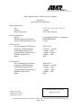
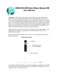
Dual Channel Wireless Transceiver
Model # 6215
User Manual
March, 2010
Introduction
American Mine Research’s Dual Channel Wireless Transceiver (MN-6215) will bring additional
features to the existing Mine Net tracking and communication system. The MN-6215 will act as
a wireless repeater and/or a wireless reader for Mine Net Messengers and Smart Tags which will
greatly expand the versatility of the communication system. This unit will have multiple
configurations to help solve a variety of mine tracking and communication difficulties.
Installation
Device Configuration:
Set the device configuration for GoPad, LilyPad or MeshPad using the configuration switches
(see table 1). For example: to select the GoPad configuration, set SW1E, SW1D, SW1B, and
SW1G to the off position. SW1F and SW1H will control the receiver squelch range for the Linx
radio transceivers and should be set to the off position. The fine adjustment squelch control for
the Tag channel (potentiometer R7) should be set to minimum squelch (counterclockwise until it
clicks) . The fine adjustment squelch control for the Messenger channel (potentiometer R4)
should be set to maximum squelch (clockwise until it clicks) to match the rest of the system
component settings. The squelch controls should only changed if necessary. Set the address
select switches using BS2 & BS1 (BS2 = MSD (Tens), BS1 = LSD (Ones)) to a unique address
between 00 and 99. Set dip switch SW1A (#1) to the on position to add 100 to the address set by
the other address switches. This gives a total of 200 different addresses available for each device
configuration (Config 1 and Config 2 are also part of the address).
Function Schematic Label SW1E SW1D SW1A SW1C SW1B SW1G CONFIG 1 CONFIG 2 ADR 100 TAG ONLY U1TX U1RX HIGH SQUELCH (418 MHz) SW1F HIGH SQUELCH (315 MHz) SW1H Physical Switch Number GoPad LilyPad MeshPad TBD #5 #4 #1 #3 #2 #7 OFF ON OFF ON OFF OFF ON ON ADDRESS ADDRESS ADDRESS ADDRESS ON for TAG ONLY applications OFF OFF OFF TBD OFF OFF OFF TBD #6 TBD TBD TBD TBD #8 TBD TBD TBD TBD Table 1. Switch Settings for the Dual Channel Wireless Transceiver
American Mine Research Inc. P.O. Box 234 Rocky Gap, VA 24366 (276)928-1712 FAX (276)928-1814
Page 1 of 4
LED Indications:
There are several different patterns that the LED will flash, each indicating something different.
1. During initialization (after cycling power) the LED will flash red on and off for ~1
second, then flash green on and off for ~1 second. This gives visual confirmation that
both colors are working. At all other times (when a Tag is near) the LED flash pattern
will be one color on and off for ¼ second, then off for ¾ second then repeating the
pattern for the next color and so on.
2. During Range Detection mode (~10 minutes following initialization)
a. A green – green pattern indicates that the Pad is in range of another Pad
b. A green – red pattern indicates that the Pad is not in range of another Pad
c. A solid red LED lasting ~10 seconds indicates the end of Range Detection mode
3. Low Battery condition is indicated by a persistent red – red flashing pattern (no green at
all). Mine Net also shows the battery levels of the Pads. Note: Low battery indication
takes precedence over Range Detection mode and can be observed at any time after
initialization (but only if a Tag is near).
Pad Deployment:
Switch on the first unit using the toggle switch located inside the cover, between the battery
covers. Observe the initialization pattern to make sure both colors are working.
Note: for optimal performance, place pads with antenna(s) running parallel to Reader antennas
(typically parallel to crosscuts).
Mesh & Lily Pad Deployment:
After the unit initializes, it will go into a range finding mode for ~10 minutes. During this time
the LED will flash green one second and red the next second if it does not “hear” another Pad.
Place the first unit within range of the nearest Reader antenna(s) (~400’ but will vary with
conditions and line of sight obstacles such as power centers). Tip – it is easiest to put the first
Pad close (~200’) since the Tag Reader does not send any range information and the first Pad
will flash green – red. Switch on the second Pad and place it in the desired location. Verify the
LED is flashing in a green – green pattern. If it is flashing a green – red pattern then it is not
“hearing” another Pad, and will have to be relocated within range or evaluated for poor
placement. Continue to deploy the Pads in this way until the desired coverage is achieved.
Go Pad Deployment:
Verify the LED is flashing a green – green pattern (only flashes when a Tag is near) and mount
to vehicle or equipment with antenna(s) running parallel with crosscuts.
Note: An external (non-IS) power source (i.e. vehicle lighting) can be used to power the device,
however, external power and alkaline batteries may not be connected at the same time.
Maintenance
The only major internal maintenance item for the MN-6215 would be to change the disposable C
cell batteries at a recommended interval (or as indicated by the battery level shown in Mine Net)
which is referenced in Appendix A of this document. When battery level is low the LED will
flash a red – red pattern persistently (but only when a tag is near). Batteries may be changed in a
permissible area which significantly reduces the maintenance burden.
American Mine Research Inc. P.O. Box 234 Rocky Gap, VA 24366 (276)928-1712 FAX (276)928-1814
Page 2 of 4
Construction
The MN-6215 is self contained in a dust proof, polyester container with 1 to 2 (configuration
dependant) bulkhead RP-SMA connectors for external quarter wave monopole whip antennas.
One bi-color bulkhead LED indicator is visible on the top/bottom (depends on mounting) of the
unit, one green and one red. External brackets allow for versatile mounting of the unit. Battery
enclosures sealed inside the hinged lid allow for ease of battery change out.
Mounting
The MN-6215 will be versatile in regards to mounting locations. The IS MN-6215 is mounted
free of cabling and operates on disposable alkaline batteries. It may be hung from roof bolts or
mounted to vehicles as needed. Non-IS versions mounted to man trips and other non-IS
equipment may be powered externally by readily available non-IS power sources (such as lamp
power).
American Mine Research Inc. P.O. Box 234 Rocky Gap, VA 24366 (276)928-1712 FAX (276)928-1814
Page 3 of 4
Dual Channel Wireless Transceiver User’s Manual
Appendix A
Specifications and Data Sheet
Physical Parameters:
Size:
Weight:
Body Construction:
6.125” W. x 4.125” H. x 3.875” D.
3 pounds
0.125” thick Polyester
Electrical Parameters:
Battery:
Required Replacement Battery:
Expected Maximum Battery Life:
Four disposable alkaline C cell batteries
ENERGIZER EN93
25 days
RF Transceiver:
Linx Technologies RF Product #:
Frequency (OOK Modulated):
Peak Radiated Output Power1:
Average Radiated Output Power 2:
Radiated Output Power3:
Range:
TRM-315-LT
315 MHz +/- 50 KHz
+11dBm / 13mW
-1.0dBm / 0.78mW
<60dBm / <1nW
TBD
RF Transceiver:
Linx Technologies RF Product #:
Frequency (OOK Modulated):
Peak Radiated Output Power1:
Average Radiated Output Power 2:
Radiated Output Power3:
Range:
TRM-418-LT
418 MHz +/- 50 KHz
+11dBm / 13mW
+7.1dBm / 5.2mW
<60dBm / <1nW
TBD
Document number 180-0609
1: During TX / High
2: During Active Period
3: During Sleep / Low
March 18, 2010
American Mine Research Inc. P.O. Box 234 Rocky Gap, VA 24366 (276)928-1712 FAX (276)928-1814
Page 4 of 4