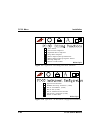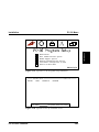
1
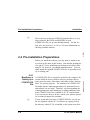
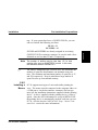
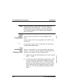
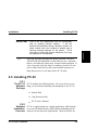
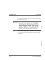
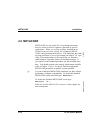
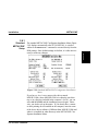
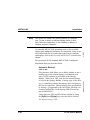
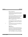
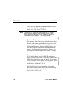
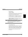
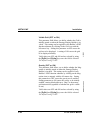
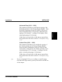
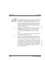
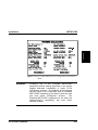
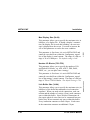
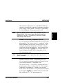
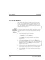
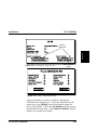
2 Installation This section provides the basic steps to install the PC-30 software. It assumes all default settings will work on your system and for your application. For more detailed installation information, or if you need to change default parameters, refer to the full installation procedure beginning with the Installation Overview section. This procedure installs PC-30 to C:\PC30. If the directory does not exist, it is created by the installation program. 1. Insert the software diskette (disk #1 if more than one) into drive A: or B:. Type: a:install ↵ (or b:install ↵ if using drive B:). 2. Click on the Install Product button on the Installation Setup menu with the left mouse key (or select it using the arrow cursor keys on your keyboard and press the [Enter] key. PC-30 is installed when you see the Installation Complete screen. 3. Select the EXIT button with the mouse or the arrow keys. The METACONF Configuration Installation menu displays. 4. Select the Mouse Co mmand Line field with the mouse or the arrow keys and modify the command line to give the correct path and command to invoke your mouse (or other pointing device). Also correct the Mouse Type field if it is PC-30 User’s Manual 2-1 Installation 2.1 Quick Installation Installation Overview Installation 5. Click the left mouse button (or press the [Enter] key. This returns you to the DOS prompt. 6. Type C:\PC30\PC30 ↵ (or just PC30 ↵ if you are in the PC-30 directory), and the Configurator is invoked. 7. To execute a strategy in the Runtime System, type: 4/23/93 not correct for your mouse and then select the OK (ENTER) button. Runtime ↵ or Runtime <strategy name> ↵ from the PC-30 directory. This chapter describes your PC-30 software package and what is required to set up and install a PC-30 system. PC-30 installation consists of the following steps: 2-2 • Checking and, if necessary, adjusting your hardware (computer system) and associated operating system software. • Installing the PC-30 copy protection key • Installing the PC-30 software • Setting up the necessary METACONF parameters PC-30 User’s Manual RG-GA3-030-005 2.2 Installation Overview Installation Installation Overview The following pre-installation sections cover connecting and using a mouse (or similar pointing device), adding or modifying a CONFIG.SYS file, and checking and possibly making adjustments to the amount of conventional memory available. If you are not familiar with these subjects, you may be able to find this expertise readily available within your organization. If you have the in-house expertise, perform these adjustments yourself. If however, you are unsure about any of these specifications or operating requirements, contact technical support. Refer to the Calling Technical Support section in Chapter 3: Before You Begin. Caution ☞ Adjustments to memory allocations can be complex and often technically demanding. You should approach any modifications in this area with caution and with full knowledge of what you are doing. It is better to ask first than to call us after you spend innumerable hours trying to adjust your system properly. It is much easier to resolve hardware incompatibility issues at this stage rather than later on, after you have built an application strategy. PC-30 User’s Manual 2-3 Installation The following paragraphs explain some computer terminology and information that may be required in setting up your PC-30 system). System Requirements Installation 2.3 System Requirements 2-4 • 640 KB conventional memory, with at least 570KB available for application programs. (See the section, Software Environment.) • A math co-processor if using a 286 or 386 based PC. Use the 80287 co-processor for 80286 systems and the 80387 co-processor for 80386 machines. (486 SX based PC’s also require a math co-processor. All other 486 based PC’s do not.) • 51⁄4 or 31⁄2 inch floppy disk drive. • 10MB hard drive; 20MB or more recommended. • Parallel port (identified by a 25 pin female connector) for PC-30 key (can be the printer port). • A mouse or similar pointing device. • Serial port or bus adapter for the mouse. • EGA or EGA/VGA display adapter and monitor. PC-30 User’s Manual RG-GA3-030-005 Although a 486 DX PC is recommended, the minimum computer requirement is a PC-AT compatible personal computer meeting the following requirements: 4/23/93 2.3.1 Hardware Requirements Installation System Requirements 2.3.2 Your system must meet the following setup requirements for PC-30 to run properly: • DOS version 3.0 or higher (see the section, DOS 5 Compatibility, if using DOS version 5.0). • A CONFIG.SYS file in your root directory that includes the lines (do not load this into high memory): FILES = 55 BUFFERS = 15 If you do not have a CONFIG.SYS file see the section, Modifying or Setting up a CONFIG.SYS FILE . Note Hint • No conventional memory resident programs such as desk accessories, RAM disks, or spoolers. These can cause unpredictable PC-30 operation and should be removed. • 570KB of conventional memory (RAM) available; more is recommended for configuring large strategies somewhat less may also be possible. Run the DOS utility CHKDSK /F to check available RAM. It is suggested that the DOS file-sharing utility SHARE.EXE be put into your AUTOEXEC.BAT file. SHARE.EXE must be installed to execute PC-30 Runtime. (The Strategy Builder does not require SHARE.EXE). Refer to the Shared File Support section in Chapter 3: Before You Begin for more information regarding shared files. PC-30 User’s Manual 2-5 Installation Software Environment Pre-Installation Preparations Device drivers, such as the ANSI.SYS terminal driver, or very large values for the FILES and BUFFERS in your CONFIG.SYS file use up conventional memory. See the section, How Much Memory do I Have? for more information on checking available memory. 4/23/93 ☞ Installation 2.4 Pre-Installation Preparations Before you install the software, you may need to attend to one or several of the items in this section. Note that the pointing device and PC-30 key installation can be done at any time before using PC-30, however, you should install them now. You can either install the supplied CONFIG.SYS file, or (possibly) modify an existing one. ☞ 2-6 A CONFIG.SYS file is required to initialize the computer for certain hardware devices and/or software packages that require special memory allocations (and other system “declarations”) to operate properly. The contents of a CONFIG.SYS file define specific operating parameters for particular devices and software you are using. Therefore, you must maintain the existing parameters while modifying or adding additional lines to the CONFIG.SYS file to conform to PC-30’s requirements. If you are not sure how to do this, consult your systems specialist or technical support for assistance. If your system does not have a CONFIG.SYS file, you can use the one supplied with the PC-30 software by copying it from the directory where PC-30 is installed, to the system root direc- PC-30 User’s Manual RG-GA3-030-005 2.4.1 Modifying or Setting up a CONFIG.SYS File Installation Pre-Installation Preparations tory. If your system does have a CONFIG.SYS file, you can edit it to include the following two lines: If FILES and BUFFERS are already assigned in an existing CONFIG.SYS file or memory manager, be sure the total values allocated are no less than 55 and 15 respectively. Note ☞ The number of buffers may be less than 15 if a disk caching utility such as SMARTDRV is used. In this case, the minimum number of buffers is 5. The FILES= statement in the CONFIG.SYS file determines the number of open files that Runtime can maintain at any one time. The minimum and maximum number of open files is 55 and 250 respectively. Keep in mind that a large number of open files uses up conventional memory. 2.4.2 Installing a Mouse PC-30 supports most types of mice and similar pointing devices. The mouse must be connected to the computer either via a COM port or via the bus interface connector (for bus type mice) per the installation instructions supplied with the pointing device. A driver, supplied with the pointing device, is also required. Once the driver information is set up in METACONF, the pointing device is automatically invoked each time you run PC-30. (See the Standard METACONF Setup – Mouse Command Line section for more information.) PC-30 User’s Manual 2-7 Installation FILES = 55 BUFFERS = 15 Pre-Installation Preparations The mouse setup in METACONF does not enable the pointing device for Runtime use. To use a mouse or similar pointing device in Runtime, follow the instructions in the section, Enabling PC-30 Options under Enabling a Mouse in Runtime. 2.4.3 DOS 5 Compatibility PC-30 Versions 4.0 and above are fully compatible with DOS 5. 4/23/93 Note Installation Earlier versions of PC-30 are compatible only if DOS 5 is not loaded high. ☞ To use earlier versions of PC-30 with DOS 5, be sure not to load DOS into high memory . 2.4.4 2-8 Before you can run PC-30, you must install the copy protection key. The software may be copied according to the license agreement, but cannot be invoked without the key. 1. Plug the key into any parallel printer port on your computer (LPT1 — LPT4). 2. Lock the key in place by tightening the captive screws. Then, you can reconnect the printer to the standard DB-25 printer connector on the other end of the key. If the key protrudes from the rear of the computer too much, you can use a short 25-pin extension cable (not supplied) between the computer and the key. The key does not interfere with the use of the printer. PC-30 User’s Manual RG-GA3-030-005 Installing the Copy Protection Key Installing PC-30 IMPORTANT ☞ Loss of the key connections does not immediately stop an ongoing Runtime session. If the key becomes disconnected during a Runtime session, an alarm sounds from the computer’s speaker and a warning message displays on the screen. PC-30 continues to control the process indefinitely if no keys are pressed on the keyboard. If the key becomes disconnected during operation, DO NOT TOUCH THE KEYBOARD (or other entry device). Reinstall the key, and when the alarm stops, resume normal operation. If a key is pressed while the alarm is sounding, you have 30 minutes to either insert the key and resume normal operation, or bring the process to a safe state before PC-30 stops. 2.5 Installing PC-30 2.5.1 The PC-30 Software Package PC-30 includes the following items. Be sure you have everything you need before installing and attempting to use PC-30. 2.5.2 Software Installation Overview • System Disk • Copy Protection Key • PC-30 User’s Manual PC-30 is supplied either on a single high density (HD) diskette or on several double density (DD) diskettes depending on the software version and your requirements. Most of the files are PC-30 User’s Manual 2-9 Installation Installation Installing PC-30 Installation IMPORTANT METACONF parameters can be readjusted any time subsequent to the initial software installation without requiring a complete re-installation. RG-GA3-030-005 ☞ You CANNOT copy the contents of the installation diskette to a PC-30 directory. For all installations, read and follow the basic instructions given in the section, Getting Around the Menu Screens, and the section, Installing the Software. After the basic software installation, you must configure METACONF. An overview of the METACONF setup procedure is contained in the section, METACONF. 4/23/93 in a compressed (archived) format and are decompressed during the installation procedure. 2-10 PC-30 User’s Manual Installation Installing PC-30 Getting Around the Menu Screens Note: ☞ The PC-30 setup procedure is menu driven. When you invoke the installation program, PC-30 prompts you to fill out a series of menu screens. You can move around the screens with or without a pointing device (such as a mouse). To enter or change information in a menu, point to a particular field or box on the display screen and press the [Enter] key. If you are using a mouse or similar device, click on the left mouse or equivalent device key. If you are using the keyboard, move forward from field to field using the [Tab] key and move backward using the [Shift Tab] combination, or the appropriate cursor keys. Clicking on the left mouse key is equivalent to pressing the [Enter] key. For the remainder of this chapter, select is used, meaning choosing a screen menu selection. From a keyboard, move to the appropriate box or field and press the [Enter] key; or using a pointing device move to the appropriate screen position and click the left or left equivalent device button. If you are not sure how to enable or get a pointing device working, a detailed description can be found in the previous section, Installing a Mouse. PC-30 User’s Manual 2-11 Installation 2.5.3 Installing PC-30 Installation 2.5.4 First, check that your hardware and software meet all the requirements described in the section, System Requirements, previously mentioned in this chapter. Reminder You CANNOT copy the contents of the installation diskette to a PC-30 directory. You must follow the installation procedure described on the following pages. 1. Turn on the power to the PC. 2. When the DOS prompt appears on the screen, insert the PC-30 software #1 Diskette into drive A: (or drive B:). 3. At the DOS prompt, type the command: 4/23/93 Installing the Software A:INSTALL ↵ ( or B:INSTALL ↵ ) RG-GA3-030-005 The Installation Setup screen appears (Figure 2.1). Figure 2.1 Installation Setup screen 2-12 PC-30 User’s Manual Installation Installing PC-30 ☞ Choose the drive on which you wish to install the PC-30 software by clicking on the Destination Drive field with the left mouse key. Enter the Destination Path you wish to install the PC-30 software. If the destination directory you specify does not exist, when you select Install Product a Create Directory menu (Figure 2.2) appears on the screen that will create the directory you specified. Figure 2.2 Create Directory menu 5. ☞ PC-30 User’s Manual Choose to install either the Configurator (Strategy & Display Builder), the Runtime or both. The default is both. If you need help operating the PC-30 Installation menu, click on the Toggle Help System button with the left mouse key. The Installation Help menu (Figure 2.3) appears. This menu lists the mouse and keyboard functions applicable to this menu. Clicking on the Toggle Help System button again with the left mouse key disables this menu. 2-13 Installation 4. Installation Figure 2.3 Toggle Help System menu 6. Next, choose any of the standard utilities (supplied with 4/23/93 Installing PC-30 RG-GA3-030-005 PC-30) at this time. To do this, select UTILITIES from the Installation Setup screen. The Utility Installation menu displays (Figure 2.4). Refer to section 2.7 PC-30 Utilities for more information regarding PC-30 utilities. Figure 2.4 Utility Installation menu Note 2-14 If you plan to use a mouse or similar pointing device during Runtime you must install the Runtime Mouse option included on the release disk. PC-30 User’s Manual Installation Installing PC-30 If for any reason you want to quit the installation at this point you can do so by selecting Abort Installation. The message in Figure 2-5 displays. Installation 7. Figure 2.5 The Confirm Abort screen Note For Runtime only packages, see the Runtime Only Systems heading in this section. 8. PC-30 User’s Manual Once you make all the installation choices, select INSTALL PRODUCT. An Installation Status screen appears below the Setup Screen (Figure 2.6) and the installation proceeds. 2-15 Installing PC-30 Installation 4/23/93 Figure 2.6 Installation Status screen You can abort the installation process at any time by pressing the [Esc] key. Figure 2.7 Installation complete screen Proceed to METACONF by selecting EXIT with the left mouse key. 2-16 PC-30 User’s Manual RG-GA3-030-005 When installation is complete the message shown in Figure 2.7 displays, indicating that you may proceed to the next step, METACONF). Installation Installing PC-30 Runtime Only Systems Installation The installation screen in a Runtime-only system is slightly different than full PC-30 systems, as shown in Figure 2.8. Figure 2.8 Installation Setup screen for Runtime-only systems The Utilities Selection menu also differs slightly from the full PC-30 system as shown in Figure 2.9. To use these menus, follow the same procedure as for the full PC-30 system software installation (Refer to the section Installing the Software for more information). Figure 2.9 Utility Installation menu for Runtime-only systems PC-30 User’s Manual 2-17 METACONF Installation METACONF sets up certain PC-30 operating parameters most of which are used to optimize operation in specific applications. When you exit the software installation described in the previous section, the (Standard) METACONF configuration menu displays. You should use the standard setup procedure if you are just starting out with PC-30, especially if your applications, for the time being, are limited to small strategies; especially if these are learning strategies. If you cannot use this standard procedure, use the extended procedure. You should examine your strategy requirements carefully (refer to Chapter 3, Before You Begin) and enter appropriate METACONF parameters to optimize system operation. ☞ 4/23/93 2.6 METACONF You can reconfigure METACONF parameters any time without performing a complete re-installation. To invoke the Standard METACONF screen from DOS type: metaconf ↵ metaconf /e ↵ Refer to Extended METACONF Parameters in this chapter for more information. 2-18 PC-30 User’s Manual RG-GA3-030-005 To invoke the Extended METACONF screen type: Installation METACONF Standard METACONF Setup The standard METACONF Configurator Installation Menu (Figure 2.10) displays automatically after PC-30 INSTALL is exited or whenever the metaconf command is executed directly from the DOS prompt. Since default settings are built-in, it is often not necessary to make any changes. Figure 2.10 Standard METACONF Configurator Installation Menu If you have a three button mouse with a driver named MOUSE.COM, (where MOUSE.COM is in either the root directory or in a directory included in the computer’s PATH), you can select O K (ENTER) and the installation process begins. Otherwise, you need to set up the mouse. If you already have a mouse or other pointing device installed on the computer, enter the name of the device driver software (if different from MOUSE.COM) and where it is installed (in what directory) in the METACONF Configurator Installation Menu. PC-30 User’s Manual 2-19 Installation 2.6.1 METACONF Installation This does not enable the pointing device for Runtime use. To use a mouse or similar pointing device in Runtime, follow the instructions in the Enabling a Mouse in Runtime section in Chapter 4. An extended METACONF parameter menu is also available and provides additional parameters for customized sizing of specific buffers and files in systems that require larger strategies and displays, refer to the Extended METACONF section in this chapter. 4/23/93 Note The parameters for the Standard METACONF Configurator Installation menu are described below. Automatic Backup? This parameter field allows you to define whether or not a backup copy of the current strategy is maintained each time a SAVE operation is performed in the Strategy Builder. When set to YES, each time the current strategy is saved in the Strategy Builder, a backup copy of the strategy is created that contains the strategy in its state prior to the last save operation. Backup strategy files are identified by having a _B appended to the end of their file name, for example, backup files for the strategy DRUM would appear as DRUM_B.*. Valid values are YES and NO and are selected by using the [PgDn] and [PgUp] keys once the field is selected. The default setting is YES. 2-20 PC-30 User’s Manual RG-GA3-030-005 (YES or NO) Installation METACONF In most cases, this command line is used to invoke the appropriate driver for your mouse hardware. For example, if you have a MouseMan serial mouse attached to your COM2: serial port, and the mouse driver is named MOUSE.COM, entering a Mouse Command Line of MOUSE PC 2 loads the mouse driver properly each time the PC-30 Configurator is invoked. The default setting for this parameter is MOUSE. If you delete the default setting, leaving the field empty, and you press the [Enter] key, the default setting is automatically restored. ☞ The full pathname for the mouse driver is optional and is not necessary if the mouse driver is located in directory included in the system’s DOS PATH. Mouse Type (3-Button or 2-Button) This parameter field allows you to define whether or not you are using a 2- or 3-button mouse for your Configurator operations. The setting of this parameter determines how the button (keys) or your mouse functions during both Strategy and Display Builder sessions. Refer to Using the Mouse section in Chapter 1: Introduction for information on how 2- and 3-button mice are used in the Configurator. PC-30 User’s Manual 2-21 Installation Mouse Command Line This parameter field is where you enter up to a 19-character DOS command line. When you execute this command, it initiates the type of mouse hardware you are using in conjunction with PC-30. METACONF Installation Valid values are 3-Button and 2-Button and are selected by using the [PgDn] and [PgUp] keys once the field is selected. The default setting is 3-Button. Graphics Printer This parameter field allows you to define the printer driver that used when printing graphic-based images in the Strategy and Display Builders only. During the installation process, only one printer driver is installed, EPSON_MX. This driver supports most EPSON compatible dot matrix printers. To print graphic-based images in Runtime, you need to define a Runtime printer in the System Configuration submenu. Four other additional printer drivers are provided on the PC-30 Utilities diskette in the PRINTERS subdirectory. These drivers include: HPPJET, NEWJET, IBMPRO, and XROX4020, and must be copied into the PC-30 system directory before they can be used by the Configurator. Refer to Appendix C: Supported Devices for a definition of the printers/drivers supported by PC-30. With the field selected, type in from the keyboard the name of the graphics printer driver to be used for printing graphics-based images during a Configurator session. The default value is EPSON_MX. 2-22 PC-30 User’s Manual 4/23/93 This does not enable the pointing device for Runtime use. To use a mouse or similar pointing device in Runtime, follow the instructions in the Enabling a Mouse in Runtime section in Chapter 4: The Strategy Builder. RG-GA3-030-005 Note Installation METACONF Net Gif Directory (SYSTEM or CURRENT) If SYSTEM is chosen, PC-30 looks for .GIF files in the PC-30 System directory. If CURRENT is chosen, PC-30 looks for the .GIF files in the current working directory. Click on this field with the left mouse key or press the [PgUp] and [PgDn] keys while the field is selected to toggle the choices. The default is SYSTEM. Note The Net Gif Directory setting only applies if the Network and/or SHADOW options are installed. Consult your local PC-30 sales representative for information about obtaining these products. Control/Graphics Grid The parameter fields displayed under these two groups perform the same operation in their respective Configurator modules. That is, the Control Grid parameters affect grid settings in the Strategy Builder and the Graphics Grid parameters affect the grid settings in the Display Builder. Since the perform the same operation, they are only described once. PC-30 User’s Manual 2-23 Installation This field specifies which directory PC-30 looks for Node block interface files (.GIF). Node block interface files are used in the Network and SHADOW options. Installation Visible Grid (OFF or ON) This parameter field allows you define whether the Grid is initially turned on when the Strategy/Display Builder is invoked. This setting can be toggled in each Builder’s EDIT function submenu by clicking on the Grid icon with the left mouse key. Setting this parameter to OFF causes the grid not to be displayed. A setting of ON causes the grid to be displayed initially. Valid values are OFF and ON and are selected by using the [PgDn] and [PgUp] keys once the field is selected. 4/23/93 METACONF Gravity (OFF or ON) This parameter field allows you to define whether the Magnetism is initially turned on when the Strategy/Display Builder is invoked. This setting can be toggled in each Builder’s EDIT function submenu by clicking on the Magnetism icon (a magnet) with the left mouse key. Setting this parameter to OFF causes the gravity not to enabled. Setting parameter to ON causes the gravity to be initially enabled, causing blocks/objects to “snap” to the nearest grid intersection (regardless of whether the grid is visible or not). Valid values are OFF and ON and are selected by using the [PgDn] and [PgUp] keys once the field is selected. The default setting is OFF. 2-24 PC-30 User’s Manual RG-GA3-030-005 The default setting is OFF. METACONF Horizontal Size (0.001 - 1000) This parameter field allows you define the spacing of the horizontal grid lines in the Strategy/Display Builder. Since the initial Configurator screens are 1000 by 1000 screen units, the default setting of 20 provides a horizontal grid spacing of 50 divisions. A setting of 100 displays a horizontal grid spacing of 10 divisions. Valid values are from 0.001 to 1000 and are entered from the keyboard once the field is selected. The default setting is 20. Vertical Size (0.001 - 1000) This parameter field allows you to define the spacing of the vertical grid lines in the Strategy/Display Builder. Since the initial Configurator screens are 1000 by 1000 screen units, a setting of 30, for example, provides a vertical grid spacing of 33.33 divisions. A setting of 100 displays a vertical grid spacing of 10 divisions. Valid values are from 0.001 to 1000 and are entered from the keyboard once the field is selected. The default setting is 20. ☞ If you are learning PC-30 or are working on a small strategy (less than 1000 logic blocks), you may not need to read the rest of this chapter. PC-30 User’s Manual 2-25 Installation Installation METACONF Installation Extended METACONF ☞ The METACONF program can provide access to an additional set of parameters, allowing you to define size boundaries for various buffers and files. Modifying these parameters can allow larger strategies to be developed within the Configurator for systems utilizing the new XMS memory support (refer to Chapter 3: Before You Begin and Appendix F: XMS and EMS Memory for more information on XMS memory). Displaying the Extended METACONF menu can only be accomplished from the DOS prompt. To bring the Extended METACONF menu up on the screen, move into your PC-30 system directory and type metaconf /e ↵ at the DOS prompt. 4/23/93 2.6.2 ☞ 2-26 Systems without XMS memory can make small incremental changes to the Extended METACONF parameters discussed in this section in order to increase their strategy sizes. If your system does not have XMS memory, you should only increase one or two parameters by a small amount. Then, run the Configurator with the edits you made. If memory error messages appear in the Configurator, the parameters you increased should be reduced until the error messages do not display. You should add XMS memory to systems that require extensive increases to these extended parameters. PC-30 User’s Manual RG-GA3-030-005 This causes the Extended METACONF CONFIGURATOR Installation menu to display (Figure 2.11). METACONF Installation Installation Figure 2.11 Extended METACONF Configurator Installation Menu WARNING PC-30 User’s Manual Increasing any of the Extended METACONF parameter’s default settings described in this section negates backward compatibility to earlier PC-30 Configurator versions. All strategies and/or displays that are edited in the Configurator after an Extended METACONF parameter(s) are altered cannot be used with most earlier Configurator versions. The Extended METACONF parameters do not effect the strategy/display’s compatibility with most earlier Runtime versions. 2-27 METACONF Installation Extended METACONF Parameters ☞ During the Configurator’s initialization, PC-30 assumes that a hypothetical strategy is going to be loaded that contains the maximum value for each extended parameter. If this hypothetical strategy does not fit into memory (XMS or other) the Configurator boot-up is aborted. 4/23/93 Extended parameters accept numerical values typed in from the keyboard. The range of values that are valid for each parameter are defined directly below each parameter name. When you enter values for a particular parameter, make sure that the value is within the range specified. Values entered above or below the valid range are clipped to the boundary it exceeds. ☞ The following paragraphs describe the functionality and valid ranges of the parameter fields available in the Extended METACONF Configurator Installation menu. Number Blocks (250-1750) This parameter allows you to specify the number of algorithm blocks you can place into a strategy. During the Configurator’s initialization, if PC-30 determines that this many blocks cannot be placed into a strategy, the Configurator boot-up is aborted and you are returned to DOS. 2-28 PC-30 User’s Manual RG-GA3-030-005 Because this maximum scenario is not always the case for actual strategies, it may be possible to exceed the defined values for certain parameters depending on the actual content of each strategy. Other parameters cannot have their defined values exceeded during actual strategy development. Each type of parameter is identified, where applicable, on the following pages. Installation METACONF Depending on the actual content of an individual strategy, it may be possible to place more blocks into a strategy than the value specified by this parameter. The range of valid settings is 250 to 1750 blocks. The default setting is # Peripheral Blocks (250-6000) This parameter field allows you to specify the number of Distributed I/O parameters that you can access in Distributed I/O device blocks in a strategy. During the Configurator’s initialization, if PC-30 determines that this number of parameters cannot be accessed, the Configurator boot-up is aborted and you are returned to DOS. Depending on the actual content of an individual strategy, it may be possible to access more parameters in a strategy than the value specified by this parameter. The range of valid settings is 250 to 6000 parameters. The default setting is 1000. Number Connections (500-3392) This parameter allows you to specify the maximum number of actual connections (wired and wireless) you can establish in a single strategy. This parameter is fixed once it is set in METACONF and cannot be exceeded from within the Configurator, regardless of the strategy’s actual content. The range of valid settings is 500 to 3392 connections. The default setting is 1500. PC-30 User’s Manual 2-29 Installation 1000. METACONF Installation This parameter is fixed once it is set in METACONF and cannot be exceeded from within the Configurator, regardless of the display’s actual content. The range of valid settings is 34 to 64 kilobytes. The default setting is 34K. 4/23/93 Max Display Size (34-64) This parameter allows you to specify the maximum size, in kilobytes, of a display file. If during a display’s construction, the display file exceeds this boundary, an error message is displayed on the screen. You need to increase the size of this parameter to resolve the error condition. Number I/O Blocks (750-1750) This parameter allows you to specify the number of I/O and Packed I/O blocks, e.g. AIN, AOUT, DIN, PAIO, PDOT, etc., you can place into a strategy. Link Buffer Size (34-64) This parameter allows you to specify the maximum size (in kilobytes) of the buffer that maintains wired connection segments. When you make wired connections, each connection and the number of vertices (if any) used consumes space within this buffer. Since Wireless Connections do not require physical wires (lines) to be connected between blocks, they do not consume any space within this buffer. Every connection consumes at least 8 bytes. Each vertex in the connection consumes an additional 5 bytes. 2-30 PC-30 User’s Manual RG-GA3-030-005 This parameter is fixed once it is set in METACONF and cannot be exceeded from within the Configurator, regardless of the strategy’s actual content. The range of valid settings is 750 to 1750 I/O blocks. The default setting is 750. Installation METACONF This parameter is fixed once it is set in METACONF and cannot be exceeded from within the Configurator; regardless of the strategy’s actual content. The range of valid settings is 34 to 64 kilobytes. The default setting is 34K. The Link Buffer uses the same RAM allocation as the Display Buffer. The memory space allocated is therefore the larger of the two - no memory is saved by making either smaller than the other. Installation Note Number I/O Devices (Compatible, 42-120) You can specify the maximum number of I/O devices with this parameter. The default setting is “compatible” which means compatible with previous versions of PC-30. The setting of compatible corresponds to 42 which is the previous fixed value of this parameter. You can increase this number by pressing the [PgDn] key while the field is selected. Numbers available are 42 (compatible), 48, 56 ... 120, in increments of 8. Note The following parameter is applicable only if the network option is installed. Number Network Nodes (Compatible, 40-256) You can specify the maximum number of Network Nodes you want this system to be compatible with. The default setting is “compatible” which means compatible with previous versions of PC-30. The setting of compatible corresponds to 32 which is the previous fixed value of this parameter. You can increase this number by pressing the [PgDn] key while the field is selected. numbers available are 32 ... 256, in increments of 8. PC-30 User’s Manual 2-31 PC-30 Utilities Installation Many utilities and options are available to assist you in using PC-30. A set of standard utilities is supplied with PC-30 and can be installed when PC-30 is installed or, selectively, at any time. The “Standard” utilities consist of those shown on the installation screen in Figure 2.13. 4/23/93 2.7 PC-30 Utilities 2.7.1 Installing Standard Utilities To selectively install or add more utilities, insert the PC-30 software Disk into drive A (or drive B) and perform the following steps: 1. At the DOS prompt, type the command: A:INSTALL (or B:INSTALL). 2-32 2. Select Install Configurator and click or type [Enter] from the keyboard to toggle the entry to NO. Also, Select Install Runtime and click or type [Enter] from the keyboard to toggle the entry to NO. 3. Set up the correct drive and path specifications as described in the section Standard METACONF Setup in this chapter. 4. Select UTILITIES . The Utility Installation menu displays (Figure 2.13). PC-30 User’s Manual RG-GA3-030-005 Press [Enter]. The Setup Installation menu displays (Figure 2.12). Installation PC-30 Utilities Installation Set these fields to NO Figure 2.12 Installation Setup screen Click on Utilities button Figure 2.13 Utility Installation menu Choose the utilities you want to install by selecting the YES/NO field to the right of it. Select the field and click the mouse key or type [Enter] from the keyboard to toggle between YES and NO. Then select OK (ENTER) and you return to the Installation Setup menu. Select INSTALL PRODUCT and the utilities you selected are installed. PC-30 User’s Manual 2-33 PC-30 Utilities Installation 2.7.2 While the word “utility” is used, the items on the menu are actually a set of Utilities, Symbol, Libraries, Printer drivers, and are standard PC-30 Options. Autocad (File Conversion) PC-30 graphics files can be interchanged with AutoCAD via the DXF file format. Graphics created in AutoCAD can be used in PC-30 by invoking the DXFTOGRP utility. For example, to create the file DRUM.GRP from the AutoCAD file DRUM.DXF, type: dxftogrp drum . The resulting .GRP file can be loaded into the PC-30 Display Builder. Likewise, graphics created in PC-30 can be used in AutoCAD by invoking the GRPTODXF utility. For example, to create the file DRUM.DXF from the display file DRUM.GRP, type: grptodxf drum . The resulting .DXF file can be loaded into AutoCAD via the DXF command DXFIN. Sample Strategy You can use the strategy, DRUM, for testing and educational purposes. This strategy is provided for you complete with interactive displays. To see the strategy in operation, type runtime drum drum1 at the prompt. The screen shown in Figure 2.14 displays. 2-34 PC-30 User’s Manual 4/23/93 Note This section briefly describes each standard utility and refers you to additional references where applicable. RG-GA3-030-005 Description of Standard Utilities PC-30 Utilities Installation Installation Figure 2.14 Drum example - Runtime screen DRUM1 The dynamic display changes as the parameters change, according to a preprogrammed sequence (drum sequencer operation). To experiment with the strategy in the configurator, invoke the configurator and load DRUM by typing: PC30 drum at the prompt. Immediately save the strategy under another name (refer to the section SAVE - Files in Chapter 4) and experiment with the renamed strategy. You can save or discard the altered DRUM strategy as you choose, but the original strategy remains unaltered. PC-30 User’s Manual 2-35 Installation ISA Symbols A set of standard ISA control symbols for incorporation into PC-30 displays is installed, creating a Symbol Library. Each symbol is an individual DOS file with a descriptive filename and an extension .SMB. Symbols can be loaded directly into PC-30 displays (see Load Symbol, under Dynamic Symbol Connection, section in Chapter 7). Standard ISA symbols provided in the PC-30 ISA Symbols Utility are: 4/23/93 PC-30 Utilities ELECTRIC.SMB H EA TEXCH.SMB L OGIC.SMB MISC.SMB M O TORS.SMB TA N KS.SMB VALV ES.SMB The Key Macro Utility is a compiler which allows you to create Key Macros using a standard ASCII file as the source file. The format is: keymac <source file> [<dest file>] where the <dest file> is a file which PC-30 interprets and executes as a MACRO. For a detailed description of Key Macros and how to compile and use them, see the Strategy Key Macros in Chapter 4. 2-36 PC-30 User’s Manual RG-GA3-030-005 Key Macros Installing the Key Macro Utility PC-30 Utilities State Field Compiler State Fields are used in PC-30 displays to show multiple text messages (from a State Field Library) during Runtime. Before a State Field Library can be generated, however, its contents must be defined in a state field source file which must then be compiled using the State Field Compiler. The format is: statecmp <source file> [<dest file>] For more information on State Fields and using the State Field Compiler, refer to Compiling State Field Source Files in the State Field Connection section in Chapter 7. Runtime Mouse The Runtime Mouse utility is a standard PC-30 option. To use a mouse or other similar pointing device with any particular Runtime strategy, you must install this utility and also select the Mouse Option when building the application strategy. This is discussed earlier in this chapter (refer to Mouse Command Line in the Standard METACONF Setup in Chapter 2, and Enabling PC-30 Options in the Enabling a Mouse in Runtime section in Chapter 4. Alarm Cache The PC-30 Alarm Cache option works in conjunction with the PC-30 database caching feature. The Alarm Cache option polls cached I/O points for alarms. This feature only applies to I/O points connected to device blocks, i.e., I/O blocks and MCONNS (Distributed I/O blocks). The Alarm Cache option allows the user to specify which device block’s I/O points will be polled during Runtime. Refer to PC-30 User’s Manual 2-37 Installation Installation PC-30 Utilities Installation Symbols A set of general purpose symbols for incorporation into PC-30 displays is installed, creating or extending the existing Symbol Library. Each symbol is an individual DOS file with a descriptive filename and an extension .SMB. Symbols can be loaded directly into PC-30 displays (refer to Load Symbol in the Dynamic Symbol Connection section in Chapter 7). General purpose symbols provided as the PC-30 Symbols Utilities are: 4/23/93 Chapter 3: Before You Begin for more information on how database caching operates. BUTTONS.S MB CART.SMB CIRCUITS.S MB FACEPLA T.SMB MACHINE.SMB PRESS.SMB Key Help This utility allows you to create Runtime Help subwindows for custom key macros created with KeyMac. These subwindows can then be used in Runtime displays to assist the operator. The Key Help utility (KEYHELP) is discussed in detail in the section Accessing On-Line Help in Chapter 8. 2-38 PC-30 User’s Manual RG-GA3-030-005 VATS.S MB Installation PC-30 Utilities Printer Drivers ☞ • Hewlett Packard PaintJet (files HPPJET.PRP & HPPJET.PTR) • IBM ProPrinter (files IBMPRO.PRP & IBMPRO.PTR) • IBM Color JetPrinter 3852 (files NEWJET.PRP & NEWJET.PTR) • Xerox 4020 Parallel Ink Jet (files XROX4020.PRP & XROX4020.PTR) Installation The following standard printers are supported by the drivers included in the Printer Driver utility: Additional drivers are available through your local PC-30 sales representative. User Algorithms User Algorithms is a standard option (refer to the section User Algorithms in Chapter 6). You must select and install this utility to build user algorithms as described. Installing User Algorithms creates the files required to build and compile these custom (USER) algorithm blocks. These files are: USER.C USER1.H USER2.H MCGEN.LIB MC.OBJ PC-30 User’s Manual 2-39 PC-30 Utilities Installation RG-GA3-030-005 4/23/93 THIS PAGE INTENTIONALLY LEFT BLANK 2-40 PC-30 User’s Manual Installation PC Test Program The PC-30 PC Test utility provides a display that allows you to test your computer system for compatibility with the PC-30 Workstation software. All essential configuration and hardware data will be listed on a display when the PC Test program is run. If an incompatibility is found, the results will be displayed in flashing red, and the minimum requirement for that parameter will be displayed in white, adjacent to it. The program will search the default drive for a CONFIG.SYS file and display the current settings for FILES and BUFFERS. If the CONFIG.SYS file is modified, the computer must be re-booted for the new configuration to be valid. When you are through using PC Test return to the PC-30 directory, if you are not already in it. 2.8.1 Installation and Startup of PC Test Software The PC Test utility, which is contained in the subdirectory PCTEST on PC-30 Utilities Disk 2 of 2, consists of one file, PCTEST.EXE . You can install the PC Test functionality by performing the steps described in the section Utilities Installation. If the program is to be run from the diskette drive, rather than copying it to the hard disk, enter the following command: A:\PCTEST\PCTEST . To invoke the PC Test from the DOS prompt, type: PCTEST and press [Enter]. The PC Test screen is shown in Figure 2.15. PC-30 User’s Manual 2-41 Installation 2.8 PC Test Program PC-30 Menu Installation Figure 2.15 PC Test display 2.9 PC-30 Menu The PC-30 Menu utility allows you to invoke installed modules, drivers, and utilities by selecting them from menu displays. This feature provides an alternative to invoking PC-30 programs by entering DOS commands, as you do without the Menu utility. Only installed programs will appear on the menus, and all items that appear will be numbered sequentially. Once all PC-30 software is installed, and the Menu utility is installed and invoked, the PC-30 Master Menu appears on the screen. After that, it appears each time you exit from a PC-30 program (except when you exit from the Display Builder to the Strategy Builder). 2-42 PC-30 User’s Manual Installation PC-30 Menu 1 Strategy and Display Builder 2 Runtime Operation 3 Editing Functions 4 Setpoint Profiler 5 Instrument Configuration Installation 9:27 am, Sat May 22, 1993 6 Industrial Keyboard Configurator 7 Program Setup 8 Return to DOS ABB Kent-Taylor Figure 2.16 PC-30 Master Menu (Typical) With the PC-30 Master Menu (Figure 2.16) or one of its submenus (Figures 2.17 - 2.19) on the screen, you can invoke listed items by typing the item number of the listed program or program category you desire. If you have an installed Microsoft compatible mouse, you can make your choice by clicking on the desired item number field with the left mouse key. The sample menus in this section show a setup with all available options installed. When you select an item on the PC-30 Master Menu that offers further choices, an appropriate submenu will appear on the screen. If you select a program such as the Strategy Builder or the Communications Builder, a screen with available filenames (Figure 2.20) will appear. With the Strategy Builder, for example, this allows you to specify the filename of an existing strategy to modify, or to choose no filename (creation of a new strategy). PC-30 User’s Manual 2-43 PC-30 Menu Installation 9:27 am, Sat May 22, 1993 1 Text Editor 2 State Field Compiler 3 Keyboard Macro Compiler 4 Help Menu Compiler 5 RRCalc Report/Recipe Generator 6 RRTest Report/Recipe Syntax Tester 7 Message Compiler 8 Return to Main Menu ABB Kent-Taylor Figure 2.17 Typical PC-30 Editing Functions Submenu 9:27 am, Sat May 22, 1993 1 Applications Builder 2 MODCELL Multiloop Processor (1706S) 3 MOD 30 Instruments (1706S) 4 MOD 30 SLU (1706S) 5 MOD 30 Communications Builder 6 LCP Upload / Download (1706S) 7 Return to Main Menu ABB Kent-Taylor Figure 2.18 Typical PC-30 Instrument Configuration Submenu 2-44 PC-30 User’s Manual Installation PC-30 Menu 1 Installation 9:27 am, Sat May 22, 1993 Workstation 2 Host Communications Option 3 Modem Support Option 4 Network Communications Option 5 Instrument Configurator (1706S) 6 Return to Main Menu ABB Kent-Taylor Figure 2.19 Typical PC-30 Program Setup Submenu Available Files BATCHR DRUM File name? C:\PC30\*.TIF M30BATCH M30DRUM (or press enter for none) Figure 2.20 Typical Screen of Available Files PC-30 User’s Manual 2-45 PC-30 Menu Installation If you enter [Alt-P] with the Master Menu on the screen, the batch commands will be shown when you make a program selection, and a pause will be inserted after a program is exited, allowing any error message to be viewed. With this pause feature selected, the prompt C:\PC30 pause Strike a key when ready . . . will appear after you exit a program. Pressing a keyboard key will bring the Master Menu to the screen. This pause feature can be toggled on/off by entering [Alt-P]. Whenever the system configuration is changed by adding options or by changing directory names, the PC-30 Menu can be changed accordingly by pressing [Alt-S] when the Master Menu is on the screen. ☞ If you elect to return to DOS via the strategy builder or other PC-30 program (with security level three), the PC-30 Master Menu will appear on the screen. (You can then choose Return to DOS on the menu. 2.9.1 2.9.1 Installation and Startup of PC-30 Menu Software NOT E: This program reads PC-30’s CONFIG.PRM file for information; therefore, it is necessary to properly install all PC-30 software first. This is performed at the end of the INSTALL operations, or by manually invoking M ETACONF.EXE. The PC-30 Menu utility, which is contained in the subdirectory PC30MENU on PC-30 Utilities Disk 2 of 2, consists of two files, PC30MENU.BAT and M AKETEMP.EXE. You can install the PC-30 Menu functionality by performing the steps described in the section Utilities Installation. 2-46 PC-30 User’s Manual Installation ☞ PC30MENU.BAT and M AKETEMP.EXE can be installed in any directory, if you choose; but if they are not both in the same directory, the M AKETEMP command in PC30MENU.BAT must be modified to include the path. The program will also load the mouse driver, upon initial entry. If a Microsoft compatible mouse driver is installed, the menu will allow the mouse to be used for menu and file selections. Entering an X as a command line parameter allows the public domain FMARK and RE LEASE programs to load and unload the mouse driver. FM ARK and RELEASE are not included in the menu software. If a "p" is used as a command line parameter to PC30MENU , the batch commands will be shown when a selection is made on the menu, and a pause will be inserted after a program is exited, allowing any error message to be viewed. This feature can be toggled on/off via the menu by pressing [Alt-P]. To invoke the PC-30 Menu from the DOS prompt, type PC30MENU or type PC30MENU P and press [Enter]. The first time the PC30MENU program is run, it searches all hard drives for PC-30 and related program files. It will prompt for the name of the text editor that will be used, and for any other needed details. A file named M AKETEMP.CFG is then created in the directory containing M AKETEMP.EXE. This file provides the program with a quick reference of required details -- what software is installed, and where it is located. PC-30 User’s Manual 2-47 Installation ☞ PC-30 Menu Industrial Operator Keyboard, 1731T Installation The initial working directory is the directory where the PC-30 files are located. To change to a new working directory, press [Alt-W] and then enter the new path name. 2.10 Industrial Operator Keyboard, 1731T Instructions for 1731T Industrial Operator Keyboard connections, programming, operation, and battery replacement are contained in IB-23H111, User’s Instructions for Industrial Operator Keyboard. This document is furnished with the keyboard. The operator Keyboard has 60 programmable keys; 20 in its top row, and 40 on its alpha keypad. All can be programmed to allow single-keystroke activation of PC-30 functions when the keyboard’s Programmed mode has been selected. The alphanumeric keys, function keys, and other keys provided on standard PC keyboards are also included, and these are enabled in the Operator Keyboard’s Alpha mode. The Operator Keyboard is toggled between Alpha mode and Programmed mode by pressing its [ALPHA] key. Thirty of the alpha pad keys are factory-programmed to perform PC-30 functions which are identified by legends on a keyboard underlay. You may choose to establish functions for some additional keys, or to define or re-define functions for any of the programmable keys, including factory-programmed ones. 2-48 PC-30 User’s Manual