1
ALBERTA AGRICULTURE AND RURAL DEVELOPMENT
Variable frequency drive
corner arm pivot case study
Part 1: Instrumentation and data collection
equipment
Prepared by: Gregg Dill, P.Eng.
December 2011
Variable Frequency Drive Corner Arm Pivot Case Study
Part 1: Instrumentation and data collection equipment
Prepared by: Gregg Dill, P.Eng.
December 2011
SUMMARY
A corner arm centre pivot operates about 20% of a circle at the maximum flow rate and 80% of the
circle at flow rates lower than the maximum flow rate. A typical flow rate range is 700 to 1200 gpm. A
corner arm centre pivot pumping unit is designed to deliver the maximum flow rate at the maximum
pressure and, therefore, operates at lower flow rates and higher pressures for most of the circle. The
variable frequency drive (VFD) adjusts the motor speed to allow the pump to deliver the required flow
rate at the required pressure which, effectively, reduces the kilowatts of power required for most of the
circle.
Instrumentation and data collection equipment required to test the power requirement for a corner
arm centre pivot without a VFD, with a VFD controlled by a pressure transducer at the pump discharge
and with a VFD controlled by a pressure transducer at the corner arm tower was assembled and tested.
Instrumentation will include an ultrasonic flow meter or a propeller flow meter, two wired pressure
transducers, three wireless pressure transducers, a power meter on the irrigation system service input, a
power meter on the input to the VFD, a wireless GPS receiver on the last tower of the centre pivot, a
wireless GPS receiver on the corner arm, and a speed monitor on the pump/motor.
The monitoring system was successfully assembled and tested.
Page 2 of 14
INTRODUCTION
A corner arm centre pivot operates about 20% of a circle at the maximum flow rate and 80% of the
circle at flow rates lower than the maximum flow rate. A typical flow rate range is 700 to 1200 gpm. A
corner arm centre pivot pumping unit is designed to deliver the maximum flow rate at the maximum
pressure and, therefore, operates at lower flow rates and higher pressures for most of the circle. The
variable frequency drive (VFD) adjusts the motor speed to allow the pump to deliver the required flow
rate at the required pressure which, effectively, reduces the kilowatts of power required for most of the
circle.
This project will measure the energy consumption of a pumping unit, controlled with and without a
VFD, for a corner arm centre pivot irrigation system and identify potential energy savings. Each system will
be monitored without a VFD, with a VFD controlled by a pressure transducer at the pump discharge, and
with a VFD controlled by a pressure transducer at the corner arm tower. Four systems will be monitored;
1) centrifugal pump and a level field, 2) centrifugal pump and an unlevel field, 3) turbine pump and a level
field, and 4) turbine pump and an unlevel field. A trailer-mounted VFD will be moved to each site and
connected to the power panel of the pump for each of the four existing corner arm centre pivot irrigation
systems. Mounting the pressure transducer at the end of the corner arm requires a wireless system which
may add $4,000 to the cost of the VFD option.
The monitoring system was successfully assembled and tested.
INSTRUMENTATION
Instrumentation will include an ultrasonic flow meter or a propeller flow meter, two wired pressure
transducers, three wireless pressure transducers, a power meter on the irrigation system service input, a
power meter on the input to the VFD, a wireless GPS receiver on the last tower of the centre pivot, a
wireless GPS receiver on the corner arm, and a speed monitor on the pump/motor. Information on
sensor and instrumentation manufacturers, model numbers and suppliers is provided in Appendix A.
Brochures and more detailed technical information about the sensors and instrumentation are included in
Appendix D.
The instrumentation and data collection developed and assembled for the 2009 Irrigation system
energy trial assessment project will be used as the basis for this project. In the 2009 project, data from
the pressure transducers and the flow meter were recorded on a CR10 data logger and the power meter
data was stored in each of the two power meters as the meters did not have a communication port. This
lead to a great amount of time spent synchronizing the data from all three data loggers to ensure the
power meter data was for the same time period as the pressure and flow data. All data, including the two
power meters data, will be collected and stored on one data logger to eliminate time discrepancies. GPS
data and pump speed (not collected in the 2009 project) will also be collected by the same data logger
eliminating the need to try and synchronize data from different data loggers to the same time. The data
logger will be located at the edge of the field near the electrical power panel.
Data logger
A Campbell Scientific Inc. (CSI) CR1000 data logger will be used to collect and pre-process the data. The
data signal from the power meters will be converted from RS485 to RS232 and connected to COM ports
one and two on the data logger. The RS232 signals from the two GPS receivers will be connected to COM
Page 3 of 14
ports three and four on the data logger. Power and communication requirements for each instrument
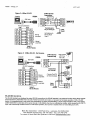
and sensor are discussed below. CR1000 channel assignments are shown in Table 1.
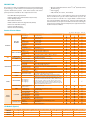
Table 1: VFD case study Campbell Scientific CR1000 data logger channel assignments.
Channel
1
2
3
4
5
6
P1
COM1
COM2
COM3
COM4
Source
Flow meter
Inlet pressure transducer
Discharge pressure transducer
Pivot point pressure transducer
Pivot end pressure transducer
Corner arm pressure transducer
Tachometer
Power panel power meter
VFD input power meter
Pivot end GPS
Corner arm GPS
Parameter
Flow rate
Inlet pressure
Discharge pressure
Pivot point pressure
Pivot end pressure
Corner arm pressure
Pump speed
Supply power
VFD power
Pivot end position
Corner arm position
Signal type
Units
Range
4-20 ma
GPM
0-1500
0.5-5.5 VDC
PSI -14.7 to 15
0-5 VDC
PSI
0-100
4-20 ma
PSI
0-100
4-20 ma
PSI
0-100
4-20 ma
PSI
0-100
0-5 VDC
RPM
0-2000
RS485/RS232 kW, kWh, Amps, V, PF
various
RS485/RS232 kW, kWh, Amps, V, PF
various
RS232
northing/easting
various
RS232
northing/easting
various
Flow meter
A GE Panametrics PT878 ultrasonic flow meter will be used to record system water flow rate data using
the CR1000 data logger at the same time interval as all the other test parameters. A 4-20 ma output
cable, supplied by GE Panametrics (p/n 704-609), will be required to transfer the instantaneous flow rate
data to the data logger.
A McCrometer M0308 McPropeller flow meter with McCrometer McSpaceSaver FS100 flow
straightener vanes will be used on systems that do not have the required pipe length before and after the
ultrasonic flow meter to ensure the required ±2% accuracy required. A McCrometer EA631 pulse
transmitter will be required to transmit the signal to the CR1000 data logger.
Power meters
Two Acuvim II power meters will be used to monitor power quality parameters. Data recorded will
include volts, amps and power factor for each leg of the 3-phases, kilowatts and kilowatt hours for each
test circle. MODBUS protocol will be used to transmit data to the data logger from the Acuvim II meters.
The data output from the power meters will be transferred using RS485 MODBUS protocol and converted
to RS232 protocol using two BlackBox IC820A converters connected to COM ports 1 and 2 on the CR1000
data logger. Power for the meters will be supplied from a 120 VAC source or from the lines being
monitored. The RS485/RS232 converters must be powered from the 12 V Power out connection of the
CR1000 to ensure a common ground. The Rx Com wire (C2 on the CR1000 wiring panel) will be connected
to the RS232 pin 2 and the Tx Com wire will be connected to RS232 pin 3. A ground must be connected
from the CR1000 Power out connection on the CR1000 wiring panel to the RS232 pin 5 to ensure there is
a common ground.
Initial communication with the Acuvim II was unsuccessful. MODBUS protocol has not been used
previously at the Agtech Centre for data collection. During the troubleshooting process, it was found that,
although MODBUS is a standard communication protocol, it requires specific software (above), to analyse
the data available from the Acuvim II. Many calls were made to suppliers for information and the
procedure to resolve the communication problem. Finally, one suggested downloading a tool to display
the data to ensure the communication settings were correct and to determine the actual format of the
data. A demo version of ModScan32 (WinTECH.com) was downloaded and used to confirm the
communication settings and the register data documented in the Acuvim II User's Manual. Many possible
Page 4 of 14
combinations were configured and tested unsuccessfully before the registers containing the required data
were identified. It was found that the data did not start from the register indicated in the Acuvim II
manual.
Since this is a unique combination of instruments, there was no specific documentation on power and
data signal requirements. The CR100 CRBasic program Acuvim_test.ComRS232.CR1 (Appendix A) ,
supplied by a Campbell Scientific Inc. Applications Engineer contacted in the troubleshooting process, was
used with a CR1000KD display/keyboard as an intermediate step to confirm the data was available from
the Acuvim II as documented. The next step was to confirm the data was available at the CR1000 COM1
port. A power configuration problem was identified during the testing process. Power for the
RS485/RS232 converter was originally supplied using a standard 120 V transformer to provide the 12 VDC
power required. With the help of the CSI Applications Engineer, it was identified that the power must be
supplied from the CR1000 Power out connection and a ground wire provided from the CR1000 Power out
connection to the converter to ensure a common ground to stabilize the data signal. The CRBasic
program Acuvim_test.Com1.CR1 (Appendix B) was developed and used to setup the MODBUS
communication between the Acuvim and CR1000 data logger. The frequency data was not available in
the location indicated in the Acuvim II documentation.
Pressure transducers
Pressure transducers will be located on the intake and discharge of the centrifugal pumps and on the
discharge of the turbine pumps. The distance from the water level to the pump discharge will be
measured for the turbine pumps. Wireless pressure transducers will be located at the pivot point, last
tower and corner arm tower and the data will be transmitted to the data logger using Phoenix Contact
900 MHz radios. The VFD will be controlled by the discharge pressure transducer for one complete circle
and by the corner-arm pressure transducer for one complete circle.
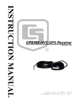
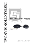
GPS
The John Deere Starfire iTC GPS was selected for identifying the location of the end of the pivot and the
corner-arm to use in determining the effect of elevation on the head required at the pump and to identify
the additional head required due to elevation. The data will also be used to identify the location of the
pivot in the 360 degree rotation. The StarFire receiver will be activated for real time kinematic (RTK)
accuracy (±2 cm). A 12 VDC power supply will be required for each GPS unit.
One receiver will be established as a base station at each test site and receivers will be positioned on
the last tower of the pivot and on the corner-arm tower. The base station will be in position for at least 24
hours prior to data collection at each test site to establish base station criteria for the site. The pivot end
and corner-arm tower location data will be transferred through a Phoenix Contact 900 MHz wireless
connection from the receivers to the CR1000 data logger located at the pump site. This will ensure that
the pivot location will be recorded at the same time as the power, pressure, speed and flow data.
The StarFire was chosen to be consistent with the GPS supplier currently used at the Agtech Centre.
Communication between the computer and the receiver will be through a John Deere StarFire iTC Radar
harness (PF80754) that includes a RS232 serial connection. A baud rate of 4800 will be required to
communicate with the StarFire iTC receiver. A 12 VDC power supply will be connected to power the
receiver through the round, 4-pin connector on the harness.
The StarFire (SF) GPS receiver is usually used as part of the John Deere guidance system rather than as
a stand-alone receiver used to provide position data to a data logger application. A specific
Page 5 of 14
communication wiring and communication procedure was not available and had to be developed step by
step with several calls to the supplier and many false starts. The first step was to identify the correct
wiring harness to connect the receiver and the computer. Identifying the correct wiring harness was
prolonged until it was recognized that the Panasonic Toughbook laptop used to communicate with the
receiver had an internal GPS system that had to be disabled before communication with the SF unit was
possible. Once the internal GPS was disabled, the software package LabView was used, as an
intermediate step, to view the data stream provided by the receiver as a NMEA string and to understand
the format of the data. The data format was found to be different than that documented in the software.
The next step was to use the Toughbook to communicate with the receiver without using Labview.
After searching the internet, a software program, iTCconfig, available from the John Deere website
http://stellarsupport.deere.com/en_US_new/categories/tools/starfire-desktop-configurator was used to
interface with the StarFire receiver to set the communication parameters. This program must be used to
set the required communication parameters on the receiver to enable communication with the CR1000
data logger. The iTCconfig software used to communicate with the iTC receiver will not communicate
with the StarFire 3000 receiver that is available at the Agtech Centre and compatible software was not
available.
After the communication parameters were set on the StarFire receiver, the receiver was connected
directly to the CR1000 data logger and the CRBasic program GPS_SF2.test.CR1 (Appendix C) was used to
confirm the NMEA string data available to the CR1000 data logger from the GPS receiver through a RS232
interface connected to COM3. The second GPS receiver will be connected to COM4. The output is shown
in Table 2. The data will be imported into an Excel spreadsheet and formatted (Table 3).
The data will be imported into an Excel spreadsheet (circle_calc.xls) and the location data will be used
to determine the location of the pivot and corner-arm relative to the pivot centre and the elevation
relative to the pump elevation (Table 4).
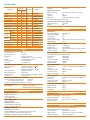
Table 2: Data format of data sent to the CR1000 data logger from the StarFire iTC GPS receiver.
"TOA5","CR1000","CR1000","29911","CR1000.Std.18","CPU:GPS_SF2_test2.CR1","57902","gpsdata"
"TIMESTAMP","RECORD","ggaid","ggautc","ggalatitude","ggan_s_ind","ggalongitude","ggae_w_ind","ggapositionfix","gganumsatellites","ggahdo
p","ggaaltitude","ggaaltutudeunits","ggageoidsep","ggageoidunits"
"TS","RN","","","","","","","","","","","","",""
"","","Smp","Smp","Smp","Smp","Smp","Smp","Smp","Smp","Smp","Smp","Smp","Smp","Smp"
"2011-10-20 16:43:00",454,"$GPGGA","224258.0","4939.558750","N","11248.469532","W","1","06","2.2","913.447","M","-16.143","M"
"2011-10-20 16:44:00",455,"$GPGGA","224358.0","4939.558729","N","11248.469352","W","1","07","2.1","913.574","M","-16.143","M"
"2011-10-20 16:45:00",456,"$GPGGA","224458.0","4939.558256","N","11248.469782","W","2","07","2.3","913.803","M","-16.143","M"
"2011-10-20 16:46:00",457,"$GPGGA","224558.0","4939.558549","N","11248.470141","W","2","07","2.1","906.469","M","-16.143","M"
"2011-10-20 16:47:00",458,"$GPGGA","224658.0","4939.558801","N","11248.470377","W","2","07","2.2","906.128","M","-16.143","M"
Table 3: StarFire iTC GPS data as it appears when opened in an Excel spreadsheet as a csv file.
id
utc
latitude
n_s
ind
longitude
e_w
ind
position
fix
10/20-16:43
454 $GPGGA
224258
4939.55875
N
11248.469532
W
1
6
10/20-16:44
455 $GPGGA
224358
4939.55873
N
11248.469352
W
1
7
10/20-16:45
456 $GPGGA
224458
4939.55826
N
11248.469782
W
2
10/20-16:46
457 $GPGGA
224558
4939.55855
N
11248.470141
W
10/20-16:47
458 $GPGGA
224658
4939.55880
N
11248.470377
W
Timestamp Record
num of
hdop
satellites
geoid
sep
geoid
units
2.2 913.447
M -16.14
M
2.1 913.574
M -16.14
M
7
2.3 913.803
M -16.14
M
2
7
2.1 906.469
M -16.14
M
2
7
2.2 906.128
M -16.14
M
altitude
alt
units
Page 6 of 14
Table 4: Circle_calc.xls spreadsheet to convert GPS data to degrees of pivot rotation.
latitude
(degree-min)
4939.55875
4939.55873
4939.55826
4939.55855
4939.55880
longitude
(degree-min)
11248.469532
11248.469352
11248.469782
11248.470141
11248.470377
altitude
(metres)
913.447
913.574
913.803
906.469
906.128
latitude
(degrees)
49.6593
49.6593
49.6593
49.6593
49.6593
longitude
(degrees)
112.8078
112.8078
112.8078
112.8078
112.8078
latitude
(m)
5523357.03
5523356.99
5523356.12
5523356.66
5523357.13
longitude
(m)
8027968.90
8027968.69
8027969.20
8027969.63
8027969.91
x
(m)
209.01
208.97
208.09
208.64
209.10
y
(m)
(degrees)
-179.42
58.5
-179.63
58.5
-179.12
58.7
-178.69
58.6
-178.41
58.5
Speed sensor
The speed sensor will be an optical sensor that will be connected directly to the CR1000 data logger P1
(pulse) channel.
Wireless radios
Phoenix Contact 900 MHz radios will be used to transfer the signal from the pressure transducers on
the center pivot and the GPS receivers to the data logger located at the pump site.
Variable Frequency Drive (VFD)
The VFD will be a Cutler-Hammer model SVX9000 supplied and connected by Rivers Electric.
Page 7 of 14
APPENDIX A
SENSORS and EQUIPMENT
Pressure transducers:
Wired:
1. pump inlet (centrifugal pump)
Manufacturer: Cole Parmer Instruments
Model: 68075-32 (24vdc) – 0.5-5.5 VDC; -14.7-15 psig
Serial #: 3109-4005395
Supplier: : Cole Palmer Instruments
2. pump discharge
Manufacturer: SSI Technologies Inc.
Model: P51-100-G-A-I36-5V-R
Serial #: 090973017 and 0909763403
Supplier:
Wireless
3. pivot point, last tower and corner arm
Manufacturer: SSI Technologies Inc.
Model: P51-100-G-A-I36-20ma
Serial #: 110102583, 11012605, 110102611, 11012643, 090763654, 090763664
Supplier:
Flow meter:
1. Manufacturer: GE Panametrics
Model: PT878
Supplier: Procon Systems Inc, Calgary
2. Manufacturer: McCrometer Inc.
Model: McPropeller M0310
Accessories: FS100 flow straightener, EA631 pulse transmitter
Supplier: Conona Electric, Lethbridge
Power meter:
Manufacturer: Accuenergy
Model: Acuvim II
Supplier: Optimum Energy, Calgary
GPS:
Manufacturer: John Deere
Model: StarFire iTC
Supplier: Western Tractor, Lethbridge
900 MHz transmitter/receiver – Pressure sensors:
Manufacturer: Phoenix Contact
Model: RAD-ISM-900-TX/RX-DC
Serial #: 97294146, 97294078, 97294191
Page 8 of 14
ID: 14663, 15425, 15437
Supplier: Phoenix Contact Canada, Milton, Ontario
900 MHz transmitter/receiver – GPS:
Manufacturer: Phoenix Contact
Model: RAD-ISM-RS232-BD
Serial #:
ID:
Supplier: Phoenix Contact Canada, Milton, Ontario
Data logger:
Manufacturer: Campbell Scientific
Model: CR1000
Supplier: Campbell Scientific Canada, Edmonton
RS485 to RS232 adapter:
Manufacturer: BlackBox
Model: IC820A
Supplier: BlackBox Canada
VFD:
Manufacturer: Cutler-Hammer
Model: SVX9000
Supplier: Rivers Electric, Taber
Page 9 of 14
APPENDIX B
Power meter CRBasic test programs
Program to test for all 35 power parameters
'Program to test for data from the Acuvim II power meter to CR1000.
'CR1000 OS22 required.
'Written by: Gregg Dill; Nov 22, 2011
''Requires CR800 OS v.3, CR1000 OS v.12, or CR3000 OS v.5 or higher
'CR1000 uses Big-endien word order.
'Declarations
Public Register(35),BatVolts,PanelTempC
'variables
Public Result 'Holds the result of the ModBus master query
'Aliases used for clarification
'Once an alias is assigned, the original variable is not available.
'Alias Register(1) = V_AN
'Alias Register(2) = V_BN
DataTable (Table,True,-1)
DataInterval (0,5,Sec,10)
Sample (1,BatVolts,FP2)
Sample (1,PanelTempC,FP2)
'Result must be a constant value (either + or -).
'If it is incrementing, there is no communication.
Sample (1,Result,FP2)
'Register data parameters are in the order they are displayed
'on the Acuvim real-time Metering screen.
'The first data available is register 4002H (16386 Dec). H=Hex
'Exception: Frequency is not displayed and does not exist in register 4000H.
Sample (35,Register(),IEEE4)
EndTable
BeginProg
SerialOpen (Com1,38400,3,0,250)
Scan(5,Sec,0,0)
Battery (BatVolts)
PanelTemp (PanelTempC,250)
'Collect data from AcuvimII starting at register 4002H (16386).
ModBusMaster(Result,Com1,38400,1,3,Register(),16386,35,3,100,0)
CallTable Table
NextScan
EndProg
Page 10 of 14
Program to test for communication using ComRS232 and theCR100KD display/keyboard
'Program to test data from AcuvimII using ComRS232 port and CR1000KD display.
'Require a null modem cable from AcuvimII to CR1000.
'Requires CR800 OS v.3, CR1000 OS v.12, or CR3000 OS v.5 or higher
'CR1000 uses Big-endien word order.
'Declarations
Public Register(10),BatVolts,PanelTempC
'variables
Public Result 'Holds the result of the ModBus master
'query
'Aliases used for clarification
'Alias Register(1) = V_AN
'Alias Register(2) = V_BN
DataTable (Table,True,-1)
DataInterval (0,5,Sec,10)
Sample (1,BatVolts,FP2)
Sample (1,PanelTempC,FP2)
Sample (1,Result,FP2)
Sample (2,Register(),IEEE4)
EndTable
BeginProg
SerialOpen (ComRS232,38400,3,0,250)
Scan(5,Sec,0,0)
Battery (BatVolts)
PanelTemp (PanelTempC,250)
ModBusMaster(Result,ComRS232,38400,1,3,Register(),16386,2,3,100,0)
CallTable Table
NextScan
EndProg
Page 11 of 14
APPENDIX C
GPS CRBasic test program
Program to verify the parameters provided by the StarFire2 NMEA gga data string.
'CR1000 Series Datalogger
'To create a different opening program template, type in new
'instructions and select Template | Save as Default Template
'date: 3 October 2011
'program author: Gregg Dill
Public rawdata As String * 500
'gga variables
Public ggaid As String
Public ggautc As String
Public ggalatitude As String
Public ggan_s_ind As String
Public ggalongitude As String
Public ggae_w_ind As String
Public ggapositionfix As String
Public gganumsatellites As String
Public ggahdop As String
Public ggaaltitude As String
Public ggaaltutudeunits As String
Public ggageoidsep As String
Public ggageoidunits As String
Public ggaage As String
Public ggarefstationID As String
DataTable (gpsdata,True,-1)
DataInterval (0,1,min,10)
Sample (1,ggaid,String)
Sample (1,ggautc,String)
Sample (1,ggalatitude,String)
Sample (1,ggan_s_ind,String)
Sample (1,ggalongitude,String)
Sample (1,ggae_w_ind,String)
Sample (1,ggapositionfix,String)
Sample (1,gganumsatellites,String)
Sample (1,ggahdop,String)
Sample (1,ggaaltitude,String)
Sample (1,ggaaltutudeunits,String)
Sample (1,ggageoidsep,String)
Sample (1,ggageoidunits,String)
' Sample (1,ggaage,String)
' Sample (1,ggarefstationID,String)
EndTable
'Main Program
Page 12 of 14
BeginProg
Scan (1,Sec,0,0)
SerialOpen (Com1,38400,0,0,500)
SerialInBlock (Com1,rawdata,500)
'parse gga data
ggaid=Mid (rawdata,1,6)
ggautc=Mid (rawdata,8,8)
ggalatitude=Mid (rawdata,17,11)
ggan_s_ind=Mid (rawdata,29,1)
ggalongitude=Mid (rawdata,31,12)
ggae_w_ind=Mid (rawdata,44,1)
ggapositionfix=Mid (rawdata,46,1)
gganumsatellites=Mid (rawdata,48,2)
ggahdop=Mid (rawdata,50,3)
ggaaltitude=Mid (rawdata,54,7)
ggaaltutudeunits=Mid (rawdata,62,1)
ggageoidsep=Mid (rawdata,64,7)
ggageoidunits=Mid (rawdata,72,1)
' ggaage=Mid (rawdata,60,3)
' ggarefstationID=Mid (rawdata,75,6)
CallTable gpsdata
NextScan
EndProg
Page 13 of 14
APPENDIX D
Instrumentation Specifications and brochures
Brochures included:
1.
2.
3.
4.
5.
6.
7.
8.
9.
10.
11.
12.
13.
14.
Campbell Scientific data logger
Acuvim II power meter
Hawkeye current transformer
McPropeller flow meter
McSpaceSaver flow straightener
GE Panametrics PT878 flow meter
John Deere StarFire iTC GPS
SSI Pressure transducer
Cole Parmer pressure transducer
Phoenix Contact 900 MHz receiver
Phoenix Contact 900 MHz transmitter
Phoenix Contact 900 MHz RS232 radio
BlackBox RS485-RS232 converter
Cutler-Hammer SVX9000 VFD
Page 14 of 14
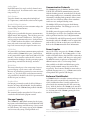
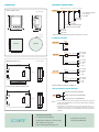
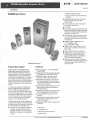
CR1000
measurement & control datalogger
A rugged
instrument with
research-grade
performance.
CR1000 Measurement and Control System
The CR1000 provides precision measurement capabilities in a rugged, battery-operated package. It consists of a measurement and
control module and a wiring panel. Standard operating range is -25° to +50°C; an optional extended range of -55° to +85°C is available.
Input/Output Terminals—
Individually configured
for ratiometric resistive
bridge, thermocouple,
switch closure, high frequency pulse, low-level ac,
serial sensors, and more.
CS I/O Port—connects with
AC-powered PCs and communication peripherals such
as phone, RF, short-haul, and
multidrop modems.
Removable Power Terminal—simplifies
connection to external power supply.
RS-232—provides
a 9-pin DCE port
for connecting a
battery-powered
laptop, serial
sensors or RS-232
modems.
{
Peripheral Port—allows data to be
stored on a CompactFlash card and/or
supports Ethernet communications.
Features
Measurement and Control Module
• 4 Mbyte memory*
• Program execution rate of up to 100 Hz
• CS I/O and RS-232 serial ports
• 13-bit analog to digital conversions
• 16-bit H8S Renesas Microcontroller with 32-bit
internal CPU architecture
• Temperature compensated real-time clock
• Background system calibration for accurate measurements over time and temperature changes
• Single DAC used for excitation and measurements
to give ratio metric measurements
• Gas Discharge Tube (GDT) protected inputs
• Data values stored in tables with a time stamp and
record number
• Battery-backed SRAM memory and clock ensuring
data, programs, and accurate time are maintained
while the CR1000 is disconnected from its main
power source
• Serial communications with serial sensors and
devices supported via I/O port pairs
• PakBus®, Modbus, DNP3, TCP/IP, FTP, and
SMTP protocols supported
The module measures sensors, drives direct communications and telecommunications, reduces data, controls external devices, and stores data and programs in
on-board, non-volatile storage. The electronics are RF
shielded and glitch protected by the sealed, stainless
steel canister. A battery-backed clock assures accurate
timekeeping. The module can simultaneously provide
measurement and communication functions. The
on-board, BASIC-like programming language supports data processing and analysis routines.
Wiring Panel
The CR1000WP is a black, anodized aluminum wiring
panel that is compatible with all CR1000 modules. The
wiring panel includes switchable 12 V, redistributed
analog grounds (dispersed among analog channels
rather than grouped), unpluggable terminal block for
12 V connections, gas-tube spark gaps, and 12 V supply on pin 8 to power our COM-series phone modems
and other peripherals. The control module easily disconnects from the wiring panel allowing field replacement without rewiring the sensors. A description of
the wiring panel’s input/output channels follows.
*Originally, the standard CR1000 had 2 MB of data/program storage, and an optional version, the CR1000-4M, had 4 MB of memory. In September
2007, the standard CR1000 started having 4 MB of memory, making the CR1000-4M obsolete. Dataloggers that have a module with a serial number greater than or equal to 11832 will have a 4 MB memory. The 4 MB dataloggers will also have a sticker on the canister stating “4M Memory”.
2
Analog Inputs
Eight differential (16 single-ended) channels measure voltage levels. Resolution on the most sensitive
range is 0.67 µV.
Communication Protocols
Pulse Counters
Two pulse channels can count pulses from high level
(5 V square wave), switch closure, or low level AC signals.
The CR1000 supports the PakBus, Modbus, DNP3,
TCP/IP, FTP, and SMTP communication protocols.
With the PakBus protocol, networks have the distributed routing intelligence to continually evaluate links.
Continually evaluating links optimizes delivery times
and, in the case of delivery failure, allows automatic
switch over to a configured backup route.
Switched Voltage Excitations
Three outputs provide precision excitation voltages for
resistive bridge measurements.
The Modbus RTU protocol supports both floating
point and long formats. The datalogger can act as a
slave and/or master.
Digital I/O Ports
Eight ports are provided for frequency measurements,
digital control, and triggering. Three of these ports can
also be used to measure SDM devices. The I/O ports
can be paired as transmit and receive. Each pair has 0
to 5 V UART hardware that allows serial communications with serial sensors and devices. An RS232-tologic level converter may be required in some cases.
The DNP3 protocol supports only long data formats.
The dataloggers are level 2 slave compliant, with some
of the operations found in a level 3 implementation.
The TCP/IP, FTP, and SMTP protocols provide TCP/IP
functionality when the CR1000 is used in conjunction
with an NL115, NL120, or third party serial IP device.
Refer to the CR1000 manual for more information.
Power Supplies
CS I/O Port
AC-powered PCs and many communication peripherals
connect with the CR1000 via this port. Connection to
an AC-powered PC requires either an SC32B or SC-USB
interface. These interfaces isolate the PC’s electrical
system from the datalogger, thereby protecting against
ground loops, normal static discharge, and noise.
Any 12 Vdc source can power the CR1000; a PS100 or
BPALK is typically used. The PS100 provides a 7-Ahr
sealed rechargeable battery that should be connected to
a charging source (either a wall charger or solar panel).
The BPALK consists of eight non-rechargeable D-cell
alkaline batteries with a 7.5-Ahr rating at 20°C.
Also available are the BP12 and BP24 battery packs,
which provide nominal ratings of 12 and 24 Ahrs,
respectively. These batteries should be connected to a
regulated charging source (e.g., a CH100 connected to
a unregulated solar panel or wall charger).
RS-232 Port
This non-isolated port is for connecting a batterypowered laptop, serial sensor, or RS-232 modem.
Because of ground loop potential on some measurements (e.g., low level single-ended measurements),
AC-powered PCs should use the CS I/O port instead of
the RS-232 port (see above).
Enclosure/Stack Bracket
A CR1000 housed in a weather-resistant enclosure can
collect data under extremely harsh conditions. The
17565 Stack Bracket allows a small peripheral to be
placed under the mounting bracket, thus conserving
space. With the bracket, the CR1000 can be attached
in a “horizontal” orientation in an ENC10/12 enclosure
(i.e., the long axis of the CR1000 spanning the short
axis of the enclosure).
Peripheral Port
One 40-pin port interfaces with the NL115 Ethernet
Interface & CompactFlash Module, the NL120 Ethernet Interface, or the CFM100 CompactFlash® Module.
Switched 12 Volt
This terminal provides unregulated 12 V that can be
switched on and off under program control.
Storage Capacity
The CR1000 has 2 MB of flash memory for the Operating System, and 4 MB of battery-backed SRAM for CPU
usage, program storage, and data storage. Data is stored
in a table format. The storage capacity of the CR1000
can be increased by using a CompactFlash card.
Above is a CR1000 mounted to the stack bracket. The Velcro
strap is for fastening a peripheral to the base of the bracket.
3
Data Storage and Retrieval Options
To determine the best option for an application, consider the accessibility of the site, availability of services (e.g., cellular phone or
satellite coverage), quantity of data to collect, and desired time between data-collection sessions. Some communication options can
be combined—increasing the flexibility, convenience, and reliability of the communications.
Keyboard Display
The CR1000KD can be used to program the CR1000,
manually initiate data transfer, and display data. The
CR1000KD displays 8 lines x 21 characters (64 x 128
pixels) and has a 16-character
keyboard. Custom menus are
supported allowing customers to
set up choices within the datalogger program that can be initiated
by a simple “toggle” or “pick list”.
Multidrop Interface
The MD485 intelligent RS-485 interface permits a
PC to address and communicate with one or more
dataloggers over the CABLE2TP two-twisted pair
cable. Distances up to 4000 feet are supported.
Ethernet
Use of an NL200, NL120, NL115, or NL100 interface
enables the CR1000 to communicate over a local network or a dedicated Internet connection via TCP/IP.
The NL115 can also store data on a CompactFlash card.
One CR1000KD can be
carried from station to station in a CR1000 network.
Radios
Radio frequency (RF) communications are supported
via narrow-band UHF, narrow-band VHF, spread
spectrum, or meteor burst radios. Line-of-sight is
required for all of our RF options.
Portable Handheld Devices
An Archer-PCon or user-supplied PDA can be used to
collect and display the CR1000’s data, transfer datalogger programs, graph data for up to two elements, and
transfer the datalogger’s data to a PC. User-supplied PDAs
require either PConnect or PConnectCE software.
Telephone Networks
The CR1000 can communicate with a PC using landlines, cellular CDMA, or cellular GPRS transceivers.
A voice synthesized modem enables anyone to call the
CR1000 via phone and receive a verbal report of realtime site conditions.
Direct Links
AC-powered PCs connect with the datalogger’s CS I/O
port via an SC32B or SC-USB interface. These interfaces provide optical isolation. A battery-powered laptop can be attached to the CR1000’s RS-232 port via an
RS-232 cable—no interface required.
Satellite Transmitters
Our NESDIS-certified GOES satellite transmitter provides one-way communications from a Data Collection
Platform (DCP) to a receiving station. We also offer
an Argos transmitter that is ideal for high-altitude and
polar applications.
External Data Storage Devices
A CFM100 or NL115 module can store the CR1000’s data
on an industrial-grade CompactFlash (CF) card (2 GB
or less). The PC reads the CF card using either the CF1
CompactFlash Adapter or a 17752 USB Reader/Writer.
The CR1000 can also store data on an SC115 2-GB
Flash Memory Drive.
Mountable Displays
The CD100 and CD295 can be mounted in an enclosure lid. The CD100 has the same functionality
and operation as the CD1000KD, allowing both data
entry and display without opening the enclosure. The
CD295 displays real-time data only.
Short Haul Modems
The SRM-5A RAD Short Haul Modem supports communications between the CR1000 and a PC via a fourwire unconditioned line (two twisted pairs).
This weather station at Denali National Park, Alaska, transmits data
via a GOES satellite transmitter.
4
Channel Expansion
4-Channel Low Level AC Module
The LLAC4 is a small peripheral device that allows
customers to increase the number of available lowlevel ac inputs by using control ports. This module is
often used to measure up to four anemometers, and is
especially useful for wind profiling applications.
Synchronous Devices for Measurement (SDMs)
SDMs are addressable peripherals that expand the datalogger’s measurement and control capabilities. For
example, SDMs are available to add control ports, analog
outputs, pulse count channels, interval timers, or even
a CANbus interface to the system. Multiple SDMs, in
any combination, can be connected to one datalogger.
Multiplexers
Multiplexers increase the number of sensors that can
be measured by a CR1000 by sequentially connecting
each sensor to the datalogger. Several multiplexers can
be controlled by a single CR1000.
The Network Planner, included in LoggerNet 4 or higher, generates device settings and configures the LoggerNet network map
for PakBus networks.
PC400, our mid-level software, supports a variety of
telemetry options, manual data collection, and data
display. For programming, it includes both Short Cut and
the CRBasic program editor. PC400 does not support
combined communication options (e.g., phone-to-RF),
PakBus® routing, or scheduled data collection.
RTDAQ is an ideal solution for industrial and realtime users desiring to use reliable data collection
software over a single telecommunications medium,
and who do not rely on scheduled data collection.
RTDAQ’s strength lies in its ability to handle the
display of high speed data.
The CR1000 is compatible with the AM16/32B (shown above)
and AM25T multiplexers.
Software
Starter Software
Our easy-to-use starter software is intended for first
time users or applications that don’t require sophisticated communications or datalogger program editing.
SCWin Short Cut generates straight-forward CR1000
programs in four easy steps. PC200W allows customers to transfer a program to, or retrieve data from a
CR1000 via a direct communications link.
LoggerNet is Campbell Scientific’s full-featured datalogger support software. It is referred to as “full-featured”
because it provides a way to accomplish almost all the
tasks you’ll need to complete when using a datalogger.
LoggerNet supports combined communication options
(e.g., phone-to-RF) and scheduled data collection.
At www.campbellsci.com/downloads you can download
starter software at no charge. Our Resource CD also
provides this software as well as PDF versions of our
brochures and manuals.
Datalogger Support Software
Our datalogger support software packages provide
more capabilities than our starter software. These
software packages contains program editing, communications, and display tools that can support an entire
datalogger network.
Both LoggerNet and RTDAQ use View Pro to display historical
data in a tabular or graphical format.
Applications
The measurement precision, flexibility, long-term reliability, and economical price of the CR1000 make it ideal for scientific, commercial,
and industrial applications.
Meteorology
The CR1000 is used in long-term climatological monitoring, meteorological research, and routine weather
measurement applications.
Wind Profiling
Our data acquisition systems can monitor conditions
at wind assessment sites, at producing wind farms,
and along transmission lines. The CR1000 makes and
records measurements, controls electrical devices, and
can function as PLCs or RTUs. Because the datalogger has its own power supply (batteries, solar panels),
it can continue to measure and store data and perform
control during power outages.
Our rugged, reliable weather station measures meteorological
conditions at St. Mary’s Lake, Glacier National Park, MT.
Sensors the CR1000 can measure include:
• cup, propeller, and
sonic anemometers
• tipping bucket
rain gages
• wind vanes
• pyranometers
• ultrasonic ranging
sensor
• thermistors, RTDs,
and thermocouples
• barometric pressure
sensors
• RH sensors
• cooled mirror
hygrometers
For turbine performance
A Campbell Scientific system
monitors an offshore wind
applications, the CR1000
monitors electrical current, farm in North Wales.
voltage, wattage, stress, and torque.
Soil Moisture
The CR1000 is compatible with the following soil
moisture measurement technologies:
• Soil moisture blocks are inexpensive sensors
that estimate soil water potential.
• Matric water potential sensors also estimate
soil water potential but are more durable than
soil moisture blocks.
• Time-Domain Reflectometry Systems (TDR)
use a reflectometer controlled by a CR1000 to
accurately measure soil water content. Multiplexers allow sequential measurement of a large
number of probes by one reflectometer, reducing
cost per measurement.
• Self-contained water content reflectometers are
sensors that emit and measure a TDR pulse.
• Tensiometers measure the soil pore pressure of
irrigated soils and calculate soil moisture.
Agriculture and Agricultural Research
The versatility of the CR1000
allows measurement of agricultural processes and equipment
in applications such as:
• plant water research
• canopy energy balance
• machinery performance
• plant pathology
• crop management
decisions
• food processing/storage
• frost prediction
• irrigation scheduling
This vitaculture site in
Australia integrates meteo• integrated pest
rological, soil, and crop
management
measurements.
6
Photo courtesy npower renewables
Typical sensors for wind assessment applications include, but are not limited to:
• sonic anemometers
• three-cup and propeller
anemometers (up to
10 anemometers can be
measured by using two
LLAC4 peripherals)
• wind vanes
• temperature sensors
• barometric pressure
• wetness
• solar radiation
Air Quality
The CR1000 can monitor and control gas analyzers,
particle samplers, and visibility sensors. It can also
automatically control calibration sequences and
compute conditional averages that exclude invalid
data (e.g., data recorded during power failures or calibration intervals).
Vehicle Testing
This versatile, rugged datalogger is ideally suited
for testing cold and hot temperature, high altitude,
off-highway, and cross-country performance. The
CR1000 is compatible with our SDM-CAN interface
and GPS16X-HVS receiver.
Road Weather/RWIS
Our fully NTCIP-compliant Environmental Sensor
Stations (ESS) are robust, reliable weather stations used
for road weather/RWIS applications. A typical ESS
includes a tower, CR1000, two road sensors, remote communication hardware, and sensors that measure wind
speed and direction, air temperature, humidity, barometric pressure, solar radiation, and precipitation.
Water Resources/Aquaculture
Our CR1000 is well-suited to remote, unattended
monitoring of hydrologic conditions. Most hydrologic
sensors, including SDI-12 probes, interface directly to
the CR1000. Typical hydrologic measurements:
• Water level is monitored with incremental shaft
encoders, double bubblers, ultrasonic ranging
sensors, resistance tapes, strain gage pressure
transducers, or vibrating wire pressure transducers.
Vibrating wire transducers require an AVW200series or another vibrating wire interface.
• Ionic conductivity measurements use one of the
switched excitation ports from the CR1000.
• Samplers are controlled by the CR1000 as a function of time, water quality, or water level.
• Alarm and pump actuation are controlled through
digital I/O ports that operate external relay drivers.
A turbidity sensor was installed in a tributary of the Cedar River
watershed to monitor water quality conditions for the city of
Seattle, Washington.
Vehicle monitoring includes not only passenger cars, but airplanes, locomotives, helicopters, tractors, buses, heavy trucks,
drilling rigs, race cars, and motorcycles.
The CR1000 can measure:
• Suspension—strut pressure, spring force, travel,
mounting point stress, deflection, ride
• Fuel system—line and tank pressure, flow, temperature, injection timing
• Comfort control— fan speed, ambient and supply
air temperature, refrigerant pressures, solar radiation, ac on and off, time-to-comfort, blower current
• Brakes—line pressure, pedal pressure and travel,
ABS, line and pad temperature
• Engine—pressure, temperature, crank position,
RPM, time-to-start, oil pump cavitation
• General vehicle—chassis monitoring, road noise,
vehicle position and speed, steering, air bag, hot/
cold soaks, wind tunnels, traction, CANbus, wiper
speed and current, vehicle electrical loads
Other Applications
• Eddy covariance systems
• Wireless sensor/datalogger networks
• Mesonet systems
• Avalanche forecasting, snow science, polar,
high altitude
• Fire weather
• Geotechnical
• Historic preservation
CR1000 Specifications
Electrical specifications are valid over a -25° to +50°C range unless otherwise specified; non-condensing environment required. To maintain electrical
specifications, Campbell Scientific recommends recalibrating dataloggers every two years. We recommend that the system configuration and critical
specifications are confirmed with Campbell Scientific before purchase.
PROGRAM EXECUTION RATE
CURRENT SOURCING/SINKING: ±25 mA
10 ms to one day @ 10 ms increments
RESISTANCE MEASUREMENTS
ANALOG INPUTS (SE1-SE16 or DIFF1-DIFF8)
MEASUREMENT TYPES: The CR1000 provides
ratiometric measurements of 4- and 6-wire full
bridges, and 2-, 3-, and 4-wire half bridges.
Precise, dual polarity excitation using any of the
3 switched voltage excitations eliminates dc errors.
8 differential (DF) or 16 single-ended (SE) individually
configured. Channel expansion provided by AM16/32B
and AM25T multiplexers.
RANGES and RESOLUTION: Basic resolution
(Basic Res) is the A/D resolution of a single
conversion. Resolution of DF measurements
with input reversal is half the Basic Res.
Range (mV)
1
DF Res (µV)
±5000
±2500
±250
±25
±7.5
±2.5
2
6
VOLTAGE RATIO ACCURACY : Assuming excitation
voltage of at least 1000 mV, not including bridge
resistor error.
±(0.04% of voltage reading + offset)/Vx
Basic Res (µV)
667
333
33.3
3.33
1.0
0.33
6
Accuracy does not include the sensor and measurement
noise. The offsets are defined as:
Offset for DF w/input reversal = 1.5·Basic Res + 1.0 µV
Offset for DF w/o input reversal = 3·Basic Res + 2.0 µV
Offset for SE = 3·Basic Res + 3.0 µV
1333
667
66.7
6.7
2.0
0.67
Offset values are reduced by a factor of 2 when
excitation reversal is used.
Range overhead of ~9% on all ranges guarantees that
full-scale values will not cause over range.
1
2
Resolution of DF measurements with input reversal.
ACCURACY3:
±(0.06% of reading + offset), 0° to 40°C
±(0.12% of reading + offset), -25° to 50°C
±(0.18% of reading + offset), -55° to 85°C (-XT only)
PERIOD AVERAGE
Any of the16 SE analog inputs can be used for period
averaging. Accuracy is ±(0.01% of reading + resolution), where resolution is 136 ns divided by the specified number of cycles to be measured.
INPUT AMPLITUDE AND FREQUENCY:
Signal (peak to peak)7
3
Accuracy does not include the sensor and measurement
noise. The offsets are defined as:
Offset for DF w/input reversal = 1.5·Basic Res + 1.0 µV
Offset for DF w/o input reversal = 3·Basic Res + 2.0 µV
Offset for SE = 3·Basic Res + 3.0 µV
Input
Voltage Range
Gain (±mV)
1
2500
10
250
33
25
100
2.5
INPUT NOISE VOLTAGE: For DF measurements
with input reversal on ±2.5 mV input range; digital
resolution dominates for higher ranges.
250 µs Integration:
0.34 µV RMS
50/60 Hz Integration:
0.19 µV RMS
With signal centered at the datalogger ground.
8
The maximum frequency = 1/(Twice Minimum Pulse Width)
for 50% of duty cycle signals.
50 Hz4
Total Time5
Settling
Time
450 µs
3 ms
20.00 ms
SE w/
No Rev
~1 ms
~20 ms
~25 ms
3 ms
DF w/
Input Rev
~12 ms
~40 ms
4
Max (V)
10
2
2
2
Max8
Freq
(kHz)
200
50
8
5
7
ANALOG MEASUREMENT SPEED:
Integration Type/ IntegraCode
tion Time
250
250 µs
60 Hz4 16.67 ms
Min. (mV)
500
10
5
2
Min
Pulse
Width
(µV)
2.5
10
62
100
~50 ms
AC line noise filter.
5
Includes 250 µs for conversion to engineering units.
INPUT LIMITS: ±5 V
PULSE COUNTERS (P1-P2)
(2) inputs individually selectable for switch closure, high
frequency pulse, or low-level ac. Independent 24-bit
counters for each input.
MAXIMUM COUNTS PER SCAN: 16.7x10⁶
SWITCH CLOSURE MODE:
Minimum Switch Closed Time: 5 ms
Minimum Switch Open Time: 6 ms
Max. Bounce Time: 1 ms open w/o being counted
SUSTAINED INPUT VOLTAGE W/O DAMAGE:
±16 Vdc max.
HIGH-FREQUENCY PULSE MODE:
Maximum Input Frequency: 250 kHz
Maximum Input Voltage: ±20 V
Voltage Thresholds: Count upon transition from
below 0.9 V to above 2.2 V after input filter with
1.2 µs time constant.
INPUT CURRENT: ±1 nA typical, ±6 nA max.
@ 50°C; ±90 nA @ 85°C
LOW-LEVEL AC MODE: Internal AC coupling removes
AC offsets up to ±0.5 V.
DC COMMON MODE REJECTION: >100 dB
NORMAL MODE REJECTION: 70 dB @ 60 Hz
when using 60 Hz rejection
Input Hysteresis: 12 mV @ 1 Hz
Maximum ac Input Voltage: ±20 V
Minimum ac Input Voltage:
INPUT RESISTANCE: 20 Gohms typical
ACCURACY OF BUILT-IN REFERENCE JUNCTION
THERMISTOR (for thermocouple measurements):
±0.3°C, -25° to 50°C
±0.8°C, -55° to 85°C (-XT only)
Sine Wave (mV RMS)
Range(Hz)
20
200
2000
5000
1.0 to 20
0.5 to 200
0.3 to 10,000
0.3 to 20,000
ANALOG OUTPUTS (Vx1-Vx3)
3 switched voltage, active only during measurement,
one at a time.
RANGE AND RESOLUTION: Voltage outputs programmable between ±2.5 V with 0.67 mV resolution.
Vx ACCURACY: ±(0.06% of setting + 0.8 mV), 0° to 40°C
±(0.12% of setting + 0.8 mV), -25° to 50°C
±(0.18% of setting + 0.8 mV), -55° to 85°C (-XT only)
Vx FREQUENCY SWEEP FUNCTION: Switched outputs
provide a programmable swept frequency, 0 to 2500 mv
square waves for exciting vibrating wire transducers.
Campbell Scientific, Inc.
USA
|
AUSTRALIA
|
|
BRAZIL
815 W 1800 N
|
CANADA
|
|
DIGITAL I/O PORTS (C1-C8)
8 ports software selectable, as binary inputs or control outputs. Also provide edge timing, subroutine interrupts/wake
up, switch closure pulse counting, high frequency pulse
counting, asynchronous communications (UART), SDI-12
communications, and SDM communications.
SWITCH CLOSURE FREQUENCY MAX: 150 Hz
EDGE TIMING RESOLUTION: 540 ns
OUTPUT VOLTAGES (no load): high 5.0 V ±0.1 V;
low <0.1
OUTPUT RESISTANCE: 330 ohms
INPUT STATE: high 3.8 to 16 V; low -8.0 to 1.2 V
INPUT HYSTERESIS: 1.4 V
INPUT RESISTANCE: 100 kohms
SWITCHED 12 V (SW-12)
One independent 12 V unregulated sources switched on
and off under program control. Thermal fuse hold current
= 900 mA @ 20°C, 650 mA @ 50°C, 360 mA @ 85°C.
CE COMPLIANCE
STANDARD(S) TO WHICH CONFORMITY IS
DECLARED: IEC61326:2002
COMMUNICATIONS
RS-232 PORTS:
9-pin: DCE port for battery-powered computer or
non-CSI modem connection.
COM1 to COM4: Four independent Tx/Rx pairs on
control ports (non-isolated); 0 to 5 VUART
Baud Rates: selectable from 300 bps to 115.2 kbps.
Default Format: 8 data bits; 1 stop bits; no parity
Optional Formats: 7 data bits; 2 stop bits; odd, even
parity
CS I/O PORT: Interface with CSI peripherals
SDI-12: Digital control ports 1, 3, 5, and 7 are
individually configured and meet SDI-12 Standard
version 1.3 for datalogger mode. Up to ten SDI-12
sensors are supported per port.
PERIPHERAL PORT: 40-pin interface for attaching
CompactFlash or Ethernet peripherals
PROTOCOLS SUPPORTED: PakBus, Modbus, DNP3,
FTP, HTTP, XML, POP3, SMTP, Telnet, NTCIP, NTP,
SDI-12, SDM
CPU AND INTERFACE
PROCESSOR: Renesas H8S 2322 (16-bit CPU with
32-bit internal core)
MEMORY: 2 MB of Flash for operating system; 4 MB
of battery-backed SRAM for CPU usage, program
storage and data storage.
CLOCK ACCURACY: ±3 min. per year. Correction
via GPS optional.
SYSTEM POWER REQUIREMENTS
VOLTAGE: 9.6 to 16 Vdc (reverse polarity protected)
EXTERNAL BATTERIES: 12 Vdc nominal
TYPICAL CURRENT DRAIN:
Sleep Mode: 0.7 mA (0.9 mA max.)
1 Hz Sample Rate (1 fast SE meas.): 1 mA
100 Hz Sample Rate (1 fast SE meas.): 16.2 mA
100 Hz Sample Rate (1 fast SE meas. w/RS-232
communication): 27.6 mA
Optional Keyboard Display On (no backlight): add
7 mA to current drain
Optional Keyboard Display On (backlight on): add
100 mA to current drain
PHYSICAL
DIMENSIONS: 9.4" x 4" x 2.4" (23.9 x 10.2 x 6.1 cm);
additional clearance required for serial cable and
sensor leads.
WEIGHT: 2.1 lbs (1 kg)
WARRANTY
3-years against defects in materials and workmanship.
HIGH-FREQUENCY MAX: 400 kHz
Logan, Utah 84321-1784
COSTA RICA
|
ENGLAND
|
|
(435) 753-2342
FRANCE
|
GERMANY
www.campbellsci.com
|
|
SOUTH AFRICA
|
SPAIN
Copyright © 2004, 2011
Campbell Scientific, Inc.
Printed November 2011
Revenue Grade with DATA-LOGGING
Real Time Metering
Email
Data-Logging
TOU
Max & Min Record
ISO9001 Certified
DESCRIPTION
The Acuvim II is a high-end multifunction power meter manufactured
by Accuenergy. It is the ideal choice for monitoring and controlling
of power distribution systems. Some of the features and electric
power parameters available on the compact Acuvim II are:
Measure Individual Harmonics from 2nd to 63rd(Acuvim IIR,Acuvim IIE)
Module Design
Data-Logging
TOU, 4 Tariffs, 12 Seasons, 14 Schedules
Acuvim II may be used as a data gathering device for an intelligent
Power Distribution System or Plant Automation System. All
monitored data is available via a digital RS485 communication
port running Modbus®-RTU Protocol. Ethernet and Profibus DP
communication are also options and with new wireless technologies
and protocols currently under development, the applications for the
Acuvim II meter are limitless.
True-RMS Measuring Parameter
ANSI C12.20(0.2 Class) and IEC 62053-22(0.2S Class)
Power Quality Analysis
Over/Under Limit Alarm
Multi Communication Ports (Eg: Ethernet, RS485)
Web Server and Email Sending
Switch Status Monitoring
Remote Switch Controlling
Acuvim II Series Meter
CATEGORY
Function; ITEM
Parameters
Phase Voltage
Line Voltage
Current
Power
Reactive Power
REAL TIME
METERING
Apparent Power
Power Factor
METERING
Frequency
Load Features
Four Quadrant Powers
Energy
Reactive Energy
ENERGY & DEMAND
Apparent Energy
Demand
TIME OF USE
Energy/max demand
TOU
DAYLIGHT SAVING
Two formats adjust
TIME
Voltage Unbalance Factor
Current Unbalance Factor
Voltage THD
Current THD
POWER QUALITY
Individual Harmonics
MONITORING
Voltage Crest Factor
TIF
Current K factor
MAX with Time Stamp
STATISTICS
MIN with Time Stamp
ALARM
OTHERS
Data Logging
COMMUNICATION
TIME
I/O OPTION
OPTION
MODULE
COMMUNICATION
Over/Under Limit Alarm
Data Logging 1
Data Logging 2
Data Logging 3
Acuvim II
Option;
Acuvim IIR
Blank NA
Acuvim IIE
V1, V2, V3, Vlnavg
V12, V23, V31, Vllavg
I1, I2, I3, In, Iavg
P1, P2, P3, Psum
Q1, Q2, Q3, Qsum
S1, S2, S3, Ssum
PF1, PF2, PF3, PF
F
Load Features
Four Quadrant Powers
Ep_imp, Ep_exp, Ep_total, Ep_net
Eq_imp, Eq_exp, Eq_total, Eq_net
Es
Dmd_P, Dmd_Q, Dmd_S, Dmd_I1, Dmd_I2, Dmd_I3
TOU, 4 Tariffs, 12 Seasons, 14 Schedules
Month/Day/Hour/Minute
Month/Week/First few weeks/Hour/Minute
U_unbl
I_unbl
THD_V1,THD_V2,THD_V3, THD_Vavg
THD_I1, THD_I2, THD_I, THD_Iavg
Harmonics 2nd to 31st ( 63rd for Acuvim IIR, Acuvim IIE)
Crest Factor
THFF
K Factor
Each phase of V & l;Total of P, Q, S, PF & F;Demad of P,Q & S;Each
phase THD of V & I;Unbalnce factor of V & I
V,I,P,Q,S,PF,V_THD & I_THD each phase and total or average;
Unbalance factor of V & I;load type;Analog Input of each channel
F, V1/2/3/lnavg, V12/23/13/lavg, I1/2/3/n/avg, P1/2/3/sum,
Q1/2/3/sum, S1/2/3/sum, PF1/2/3, PF, U_unbl, I_unbl, Load Type,
Ep_imp, Ep_exp, Ep_total, Ep_net, Eq_imp, Eq_exp, Eq_total,
Eq_net, Es, THD_V1/2/3/avg, THD_I1/2/3/avg, Harmonics 2nd to
63rd, Crest Factor, THFF, K Factor, sequence and phase angles, DI
counter, AI, AO, Dmd P/Q/S, Dmd I1/2/3
RS485 Port,Half Duplex,
Optical Isolated
Real Time Clock
Switch Status (DI)
Year, Month, Date, Hour, Minute, Second
Digital Input (Wet)
Power Supply for DI
24 Vdc
Relay Output (RO)
Digital Output (DO)
Pulse Output (PO)
Analog Input (AI)
Analog Output (AO)
Ethernet
Profibus-DP
RS485 Module
NO, Form A
Photo-MOS
By using DO
0(4)~20mA, 0(1)~5V
0(4)~20mA, 0(1)~5V
10M/100M, Modbus-TCP, HTTP Webpage, Email
Profibus-DP/V0
Additional Modbus RTU
Modbus®-RTU Protocol
I/O Module (Option)
Module Name Digital Input (DI) Power Supply For DI (24V) Digital Output (DO) Relay Output (RO) Analog Input (AI) Analog Output (AO)
AXM-IO1
AXM-IO2
AXM-IO3
6
4
4
1
2
2
2
2
2
Communication Module (Option)
Module Name
AXM-NET
AXM-PROFI
AXM-RS485
Spec
10M/100M self-adaptable, RJ45 Jack Modbus®-TCP/IP Protocol HTTP Web page browser Email sending on time interval or on event
Profibus-DP/V0 Input Byte (typical): 32 byte Output Byte (typical): 32 Byte EN50170 vol.2 compliance
Profibus slave mode, baud rate self-adaptable up to 12M
Modbus®-RTU Protocol
APPLICATIONS
Metering of distribution feeders, transformers, generators,
capacitor banks and motors
Medium and low voltage systems
Commercial, industrial, utility
Power quality analysis
Data Logging
FEATURES
Metering
Voltage V1, V2, V3, Vlnavg, V12, V23, V31, Vllavg
Current I1, I2, I3, In, Iavg
Power P1, P2, P3, Psum
Reactive Power Q1, Q2, Q3, Qsum
Apparent Power S1, S2, S3, Ssum
Frequency F
Power Factor PF1, PF2, PF3, PF
Energy Ep_imp, Ep_exp, Ep_total, Ep_net
Reactive Energy Eq_imp, Eq_exp, Eq_total, Eq_net
Apparent Energy Es
Demand Dmd_P, Dmd_Q, Dmd_S, Dmd_I1, Dmd_I2, Dmd_I3
Load Features
Four Quadrant Powers
parameters is over or under its setting limit and persists over the
specified time interval, the event will be recorded with time stamps
and trigger the Alarm DO output. The 16 indicated parameters can
be selected from any of the 51 parameters available.
I/O option module
The E-module® technique was adopted for its flexibility and easy
expansion of the I/O function of Acuvim II. A maximum of 3
modules can be used for one meter. Digital input, digital output,
pulse output, relay output, analog input and analog output are
provided by I/O option module.
Communication
RS485, Industry standard Modbus®protocol
Module Option: Ethernet module, Profbus-DP module
Dual RS485 communication ports
Display
Clear and large character LCD Screen display with white back light
Wide environmental temperature endurance
Display Load percentage, 4 quadrants power and load nature
Outline
Small Size 96×96 DIN or 4’’ ANSI Round
Monitoring
Data_logging
The Acuvim IIR, Acuvim IIE, model offers 4MB of onboard data
logging memory to be used for historical trending. There are
3 assignable historical logs where the majority of the metering
parameters can be recorded. A real time clock allows for any logged
events to be accurately time stamped.
Power Quality
nd
rd
Voltage Harmonics 2 to 63 and THD
nd
rd
Current Harmonics 2 to 63 and THD
Voltage Crest Factor
THFF (TIF)
Current K Factor
Voltage Unbalance Factor U_unbl
Current Unbalance Factor I_unbl
Max/Min Statistics with Time Stamps
Time of use
Alarms
Limits can be set for up to 16 indicated parameters and can be
set with a specified time interval. If any input of the indicated
TYPICAL WEB PAGE FROM Acuvim II SERIES
User can assign up to 4 different tariffs (sharp, peak, valley and
normal) to different time periods within a day according to the
billing requirements. The meter will calculate and accumulate
energy to different tariffs according to the meter’s internal clock
timing and TOU settings.
DATA LOGGING FROM Acuvim II SERIES
Data Logging
Max & Min Record
SOE Record
Alarm Record
Harmonics
Acuvim II as Web Server
Internet
Router
Router
TYPICAL WIRING
B
LINE
LINE
LINE
A
C
N
A
1A FUSE
B
C
A
N
I11
I12
I22
I12
Acuvim II
I31
I32
LOAD
3LN, 2CT
2LN, 2CT*
LINE
A
1A FUSE
LINE
B
C
A
1A FUSE
I12
C
I22
1A FUSE
Terminal Block
I11
V N V3 V2 V1
I12
I11
V N V3 V2 V1
I12
I21
I21
Acuvim II
I31
I31
I32
I32
I32
LOAD
LOAD
2LL, 3CT
LINE
2LL, 2CT
LINE
A
1A FUSE
N
LINE
B
Terminal Block
A
1A FUSE
N
Terminal Block
I11
I12
I12
I11
V N V3 V2 V1
I12
I21
Acuvim II
1A FUSE
Terminal Block
I11
V N V3 V2 V1
I21
I22
I22
I22
I31
I31
I32
I32
I32
LOAD
2LL, 1CT *
V N V3 V2 V1
I21
Acuvim II
I31
LOAD
Acuvim II
I22
I31
2LN, 1CT*
V N V3 V2 V1
I21
Acuvim II
I22
LOAD
C
B
Terminal Block
Terminal Block
I11
Acuvim II
I22
I32
LINE
V N V3 V2 V1
I21
LOAD
3LN, 3CT
B
I12
I31
LOAD
A
I11
V N V3 V2 V1
I22
I32
N
1A FUSE
I21
Acuvim II
I31
C
N
Terminal Block
I11
V N V3 V2 V1
I21
B
C
Terminal Block
Terminal Block
A
B
1A FUSE
LOAD
Single Phase 3 Line
Note: "*" wiring diagram not applicable to Acuvim IIR , Acuvim IIE
Single Phase 2 Line
Acuvim II
SPECIFICATIONS
METERING
Parameters
Voltage
Current
Power
Reactive Power
Apparent Power
Power Demand
Reactive Power Demand
Apparent Power Demand
Power Factor
Frequency
Primary
Energy
Secondary
Reactive Primary
Energy
Secondary
Apparent Primary
Energy
Secondary
Harmonics
Phase Angle
Unbalance Factor
Running Time
Accuracy
Acuvim II
Acuvim IIR
Acuvim IIE
0.2%
0.2%
0.5%
0.5%
0.5%
0.5%
0.5%
0.5%
0.5%
0.2%
0.5%
0.5%
0.5%
0.5%
0.5%
0.5%
2.0%
2.0%
2.0%
0.2%
0.2%
0.2%
0.2%
0.2%
0.2%
0.2%
0.2%
0.2%
0.2%
0.2%
0.2%
0.2%
0.2%
0.2%
0.2%
2.0%
2.0%
2.0%
Resolution
Range
0.1V
0.1mA
1W
1var
1VA
1W
1var
1VA
0.001
0.01Hz
0.1kWh
0.001kWh
0.1kvarh
0.001kvarh
0.1kVAh
0.001kVAh
0.01%
0.1°
0.1%
0.01h
20V~1000kV
5mA~50000A
-9999MW~9999MW
-9999MVar~9999Mvar
0~9999MVA
-9999MW~9999MW
-9999MVar~9999Mvar
0~9999MVA
-1.000~1.000
45.00~65.00Hz
0-99999999.9kWh
0-999999.999kWh
0-99999999.9kvarh
0-999999.999kvarh
0-99999999.9kVAh
0-999999.999kVAh
0.0%~100.0%
0.0°~359.9°
0.0%~100.0%
0~9999999.99h
INPUT
Current Inputs (Each Channel)
Nominal Current 5A /1A
Metering Range 0~10A ac
Withstand 20Arms continuous,
100Arms for 1 second, non-recurring Burden 0.05VA (typical) @ 5Arms
Pickup Current 0.1% of nominal
Accuracy 0.2% full scale
Voltage Inputs (Each Channel)
Nominal Full Scale 400Vac L-N, 690Vac L-L (+20%)
Withstand 1500Vac continuous
2500Vac, 50/60Hz for 1 minute
Input Impedance 2Mohm per phase
Metering Frequency 45Hz~65Hz
Pickup Voltage 10Vac (30Vac for Acuvim IIR,Acuvim IIE)
Accuracy 0.2% full scale
Energy Accuracy (Acuvim IIR, Acuvim IIE)
Class 0.2S
Active (according to IEC 62053-22) (according to ANSI C12.20)
Class 0.2
Reactive (according to IEC 62053-23) Class 2
Harmonic Resolution
Metered Value Acuvim II: 31st harmonic
Acuvim IIR,Acuvim IIE: 63rd harmonic
COMMUNICATION
RS-485 (Standard)
MODBUS RTU Protocol
2-wire connection
Up to 38400 baud rate
Ethernet (Optional)
10M/100M BaseT
MODBUS® TCP/IP Protocol
Data Browsing through HTTP
Sending e-mail automatically
PROFI-BUS (Optional)
PROFIBUS-DP/V0 Protocol
Work as PROFIBUS slave, baud rate adaptive, up to 12M
Typical input bytes: 32, typical output bytes: 32
PROFIBUS standard according to EN 50170 vol.2
Universal CONTROL POWER
AC or DC
AC/DC Control Power
Operating Range 100~415Vac, 50/60Hz; 100~300Vdc
Burden 5W
Frequency 50/60Hz
Withstand 3250Vac, 50/60Hz for 1 minute
Installation Category III (Distribution)
Low Voltage DC Control Power (Optional)
Operating Range 20~60Vdc
Burden 5W
I/O OPTION
Digital Input
20~220Vac/dc
Input Voltage Range
2mA
Input Current (Max)
15V
Start Voltage
5V
Stop Voltage
Pulse Frequency (Max)
100Hz, 50% Duty Ratio (5ms ON and 5ms OFF)
SOE Resolution
2ms
Digital Output (DO) (Photo-MOS)
Voltage Range
Load Current
Output Frequency
Isolation Voltage
0~250Vac/dc
100mA (Max)
25Hz, 50% Duty Ratio (20ms ON, 20ms OFF)
2500Vac
Relay Output (RO)
Switching Voltage (Max) 250Vac, 30Vdc
5A(R), 2A(L)
Load Current
10ms (Max)
Set Time
30mΩ (Max)
Contact Resistance
3000Vac
Isolation Voltage
1.5x10⁷
Mechanical Life
Analog Output (AO)
0~5V/1~5V, 0~20mA/4~20mA (Optional)
Output Range
0.5%
Accuracy
50ppm/°C typical
Temperature Drift
500Vdc
Isolation Voltage
15V
Open Circuit Voltage
Analog Input (AI)
0~5V/1~5V, 0~20mA/4~20mA (Optional)
Input Range
0.2%
Accuracy
50ppm/°C typical
Temperature Drift
500Vdc
Isolation Voltage
Power Supply for DI (24Vdc)
Output Voltage
24Vdc
Output Current
42mA
Load (Max)
21 DIs
OPERATING ENVIRONMENT
Operation Temperature - 25°C to 70°C
Storage Temperature - 40°C to 85°C
Relative Humidity 5% to 95% non-condensing
Pollution Degree 2
STANDARD COMPLIANCE
Measurement Standard IEC 62053-22; ANSI C12.20
Environmental Standard IEC 60068-2
Safety Standard
IEC 61010-1, UL 61010-1
EMC Standard
IEC 61000-4/-2-3-4-5-6-8-11, CISPR 22
Outlines Standard
DIN 43700, ANSI C39.1
ORDERING INFORMATION
DIMENSIONS
DIN Rail Option Frequency Current Input Power Supply
Acuvim II Dimensions
Unit : mm (inches)
Acuvim
P1: 100~415Vac, 50/60Hz
100~300Vdc
P2: 20~60Vdc
5A: 5Amp
1A: 1Amp
91.00 (3.583)
96.00 (3.800)
Multifunction Power Meter
H
P
E
50: 50Hz
60: 60Hz
D: Standard with LCD display
M: DIN rail mount (no LCD)
V/A
35.90
(1.413)
96.00 (3.800)
Acuvim II
Acuvim IIR
Acuvim IIE
50.70 (1.996)
102.00 (4.016)
Acuvim II Base Meter Ordering Example: Acuvim IIR - 60 - 5A - P1
I/O Option module
92.00 (3.622)
Module 1
Cut Out
Cut Out
AXM-IO1
1
Module 2
2
92.00 (3.622)
Module 1
AXM-IO2
IO Module Dimensions
1
Analog Output Type
Module 2
Unit : mm (inches)
2
Analog Output Type
90.00 (3.543)
Module 1
AXM-IO3
55.60 (2.189)
1
Analog Input Type
Module 2
2
Analog Input Type
19.50 (0.768)
A: 4~20mA
B: 0~20mA
C: 1~5V
D: 0~5V
A: 4~20mA
B: 0~20mA
C: 1~5V
D: 0~5V
A: 4~20mA
B: 0~20mA
C: 1~5V
D: 0~5V
A: 4~20mA
B: 0~20mA
C: 1~5V
D: 0~5V
IO Module Ordering Example: AXM-IO2-1A
Communication Module Dimensions
Communication Option Module
90.00 (3.543)
NET: Ethernet Module (AXM-NET)
PROFI: Profibus Module (AXM-PROFI)
AXM-
RS485: Modbus®-RTU (AXM-RS485)
55.60 (2.189)
Note: 1. No more than 2 of the same I/O modules may be attached to the meter
22.00 (0.866)
(example: Two AXM-IO2). The same two IO modules must be a different
component number.
2. A maximum of 3 modules may be attached to the meter. If a
communication module is used (example: AXM-NET ), it must be
installed on the back of the meter FIRST before the other module are
attached.
Accuenergy Corporation
Los Angeles-Toronto-Beijing
North America Toll Free: 1-877-721-8908
Web: www.accuenergy.com
Email: [email protected]
Revision Date: Jul., 2010
Document #1040E1104
CURRENT MONITORING
681x-5A Series
Split-Core Current Transformers with
Current Mode Output
The Hawkeye Series of split-core current transformers provide a 0-5AAC output
for use with transducers, data loggers and chart recorders.
������
�
��������
DIMENSIONS
�
�
�
�
�
�
�
�
�
�
�
APPLICATIONS
■ Use with transducers
■ Data logging
■ Recording
�
�
�
�
�
�
Split-Core Current Transformers
�
�����
�����
�������
�������
�������
�����
�����
�����
�����
�����
�����
�����
�����
�������
��������
��������
��������
�����
������
�������
�������
�������
�����
�����
�����
�����
�����
�����
������� �������
������� �������
������� �������
������� �������
������� ��������
������� ��������
������� ��������
������� �������
������� �������
������� �������
������� ��������
������� ��������
�����
�����
�����
�����
�����
�����
������� ��������
������� ��������
������� �������
������� �������
������� ��������
������� ��������
SPECIFICATIONS
Output at Rated Current
Rated Input Current
Frequency Range
Leads
Temperature Range
Humidity Range
Insulation Class
5 Amps AC
See ordering table
50/60Hz
18 AWG, UL 1015 twisted pair, 6 FT. (1.8m) length
-15° to 60°C*
0-95% non-condensing
600VAC**
* H6812-2000-5A 80 to 100% loaded, -15° to 50°C, H6810-100A-5A, accuracy & burden specified at 40°C
**Do not apply 600V Class current transformers to circuits having a phase-to-phase voltage greater
than 600V, unless adequate additional insulation is applied between the primary conductor and the
current transformers. Veris assumes no responsibility for damage of equipment or personal injury
caused by products operated on circuits above their published ratings.
WIRING
X2 Black
H2
ORDERING INFORMATION
H1
“Source
Side”
X1 White
MODEL
RATIO
F. S. ACCURACY
BURDEN
CAPACITY IN VA
H6810-200A-5A
H6810-300A-5A
H6811-400A-5A
H6811-600A-5A
H6811-800A-5A
H6812-800A-5A
H6812-1200A-5A
H6812-1600A-5A
200:5
300:5
400:5
600:5
800:5
800:5
1200:5
1600:5
1%
1%
1%
1%
1%
1%
1%
1%
2.5VA
2.5VA
5VA
5VA
12.5VA
5VA
22.5VA
22.5VA
ACCESSORIES
Universal Mounting Bracket Kit...See page 234
800.354.8556
503.598.4564
www.veris.com
©2006Veris Industries
73
Propeller
MODEL
CONFIGURATION SHEET
BOLT-ON SADDLE FLOWMETER
M0300
DESCRIPTION
The M0300 Bolt-On Saddle Flowmeter features a fabricated
stainless steel saddle with McCrometer’s unique drive and
register design. The stainless steel saddle eliminates the
fatigue-related breakage common to cast iron and aluminum
saddles and provides unsurpassed corrosion protection.
Fabricated stainless steel construction offers the additional
advantage of being flexible enough to conform to out-of-true
pipe. The Model M0300 is manufactured to comply with
applicable provisions of American Water Works Association
Standard No. C704-02 for propeller-type flowmeters. As with
all McCrometer propeller flowmeters, standard features
include a magnetically coupled drive, instantaneous flowrate
indicator and straight reading, six-digit totalizer.
Impellers are manufactured of high-impact plastic, capable of
retaining their shape and accuracy over the life of the meter.
Each impeller is individually calibrated at the factory to
accommodate the use of any standard McCrometer register,
and since no change gears are used, the M0300 can be fieldserviced without the need for factory recalibration. Factory
lubricated, stainless steel bearings are used to support the
impeller shaft. The shielded bearing design limits the entry
of materials and fluids into the bearing chamber providing
maximum bearing protection.
The instantaneous flowrate indicator is standard and
available in gallons per minute, cubic feet per second, liters
per second and other units. The register is driven by a
flexible steel cable encased within a protective vinyl liner.
The register housing protects both the register and cable
drive system from moisture while allowing clear reading of
the flowrate indicator and totalizer.
INSTALLATION
Standard installation is horizontal mount. If the meter is to
be mounted in the vertical position, please advise the
factory. A straight run of full pipe the length of ten pipe
diameters upstream and two diameters downstream of the
meter is recommended for meters without straightening
vanes. Meters with optional straightening vanes require at
least five pipe diameters upstream and two diameters
downstream of the meter.
The McCrometer Propeller
flowmeter comes with a
standard instantaneous
flowrate indicator and
straight-reading totalizer.
An optional FlowCom
register is also available.
Typical face plates.
APPLICATIONS
Center pivot systems
Sprinkler irrigation systems
Drip irrigation systems
Golf course and park water management
Gravity turnouts from underground pipelines
Commercial nurseries
Water and wastewater management
3255 WEST STETSON AVENUE • HEMET, CALIFORNIA 92545 USA
TEL: 951-652-6811 • 800-220-2279 • FAX: 951-652-3078
www.mccrometer.com
Printed In The U.S.A
Lit. #24517-00 Rev.1.9/08-11
Copyright © 1999-2011 McCrometer, Inc. All printed material should not be changed or altered without permission of McCrometer. Any published
pricing, technical data, and instructions are subject to change without notice. Contact your McCrometer representative for current pricing, technical data,
and instructions.
BOLT-ON SADDLE METER M0300
plastic, retaining their shape and accuracy over the
life of the meter. High temperature impeller is optional.
SPECIFICATIONS
PERFORMANCE
OPTIONS
ACCURACY/REPEATABILITY: ±2% of reading
guaranteed throughout full range; ±1% over reduced
range; Repeatability 0.25% or better
MAXIMUM TEMPERATURE: (Standard Construction)
160°F constant
PRESSURE RATING: 150 psi
MATERIALS
BEARING ASSEMBLY: Impeller shaft is 316 stainless steel.
Ball bearings are 440C stainless steel.
MAGNETS: (Permanent type) Cast or sintered Alnico
BEARING HOUSING: Brass; Stainless Steel optional
SADDLE: 304 stainless steel construction
REGISTER: An instantaneous flowrate indicator and
six-digit straight-reading totalizer are standard. The
register is hermetically sealed within a die cast
aluminum case. This protective housing includes a
domed acrylic lens and hinged lens cover with locking
hasp.
Saddle can be constructed to fit any outside diameter
pipe dimensions, including metric sizes
Can be used on a variety of pipe materials such as
steel, plastic, cast iron, cement or asbestos cement
Register extensions
All stainless steel bearing assembly
High temperature construction
“Over-Run” bearing assembly for higher than normal
flowrates
Electronic propeller meter available in all sizes of this
model
A complete line of flow recording / control
instrumentation
Blank repair saddle
Canopy boot
IMPELLER: Impellers are manufactured of high-impact
Meter Tube Installation Cut-Out Detail
M0300
Meter and Nominal Pipe Size
Maximum Flow U.S. GPM
Minimum Flow U.S. GPM
Approx. Head Loss in Inches at Max. Flow
Approx. Shipping Weight-lbs.
A (inches)
B (inches)
C (inches)
D (inches)
E (inches)
4”
600
50
23.00
18
7 5/8
8 1/4
7
4*
10 3/4
6”
1200
90
17.00
22
15
10 3/4
8
5 1/8*
14
8”
1500
100
6.75
26
15
10 3/4
8
6*
15
DIMENSIONS
10”
1800
125
3.75
30
15
10 3/4
9 1/2
7*
17
12”
2500
150
2.75
34
15
11 3/4
9 1/2
7 1/4
19
14”
3000
250
2.00
38
15
13 3/4
9 1/2
7 1/4
20 5/8
16”
4000
275
1.75
44
15
13 3/4
9 1/2
7 1/4
21 5/8
For larger sizes see Model M1400.
McCrometer reserves the right to change design or specification without notice.
*Standard pipe only. For other than standard pipe, consult factory for cutout dimensions.
Please specify the inside diameter of the pipe when ordering.
FOR MORE INFORMATION CONTACT:
3255 WEST STETSON AVENUE • HEMET, CALIFORNIA 92545 USA
TEL: 951-652-6811 • 800-220-2279 • FAX: 951-652-3078
www.mccrometer.com
Printed In The U.S.A
Lit. #24517-00 Rev.1.9/08-11
Copyright © 1999-2011 McCrometer, Inc. All printed material should not be changed or altered without permission of McCrometer. Any published
pricing, technical data, and instructions are subject to change without notice. Contact your McCrometer representative for current pricing, technical data,
and instructions.
Mc SpaceSaver
Flow Meter
TM
The tight spot
solution that
saves money
McSpaceSaver: The tig
Conserve water and save money
with the high accuracy flow meter
that fits almost anywhere
Developed with a breakthrough design that combines
advanced flow conditioning and propeller meter
technologies, the Mc SpaceSaver™ Flow Meter from
McCrometer delivers superior accuracy, lower
installation costs and long-life with low maintenance.
It’s the ideal money-saving flow measurement
solution to help farmers, water district engineers
and irrigation dealers cope with the latest water
metering programs.
Unique space-saving design shrinks
straight-run requirements by up to
for a tight fit in crowded installation
Built-in flow conditioning and proven
propeller meter technology deliver high
accuracy of ±2% with ±0.25 repeatability
For more than 50-years, McCrometer has been the
leader in developing innovative flow measurement
solutions designed specifically for rugged agricultural
and turf irrigation operations.The first McCrometer
flow meters were designed for farmers by farmers
who knew first-hand the challenge of bringing water
reliably and efficiently to crops without wasting a
drop or a nickel.
2
2
How flow conditioning works
The Mc SpaceSaver Flow Meter operates over a wide
15:1 flow range and supports the most popular 6 and
8-inch irrigation line sizes. It is designed
with a built-in flow straightener
assembly that greatly enhances
measurement performance. As the
upstream flow in an irrigation line
approaches the Mc SpaceSaver,
its built-in straightener mixes and
shapes the liquid flow into a smooth
stream before it reaches the impeller to optimize
measurement performance.
4
1
3
Reduced straight-run
eliminate piping mate
labor to cut total inst
ght spot meter
5
s pipe
50%
ns
The result is greater flow measurement accuracy, in real
world installations of up to ±2 percent, with ±0.25
percent repeatability. The Mc SpaceSaver’s
built-in flow straightener allows it to
be installed in close proximity to
chemigation, butterfly and gate
valves, or out-of-plane elbows, and
reducers with excellent measurement stability -- compared to mag
and other flow meters, which specify
accuracy based on ideal laboratory flow conditions.
The Mc SpaceSaver is designed with heavy-duty
propeller meter technology for rugged agricultural
service. Featuring a self-cleaning propeller design,
the Mc SpaceSaver prevents the build-up of solids.
Its unique magnetic coupling system keeps the
register drive isolated from the flow while permitting
unrestricted movement of the impeller. Free rotation
of the impeller also is assured by factory-lubricated
stainless steel bearings.
1
4
The straight story on straight runs
3
5
Power-free design eliminates failure-prone
batteries and keeps data safe with an
easy-to-use, standard register
Advanced propeller meter prevents solids
build-up for trouble-free performance in
rugged agricultural and turf operations
requirements
erial and extra
allation costs
The advanced Mc SpaceSaver from McCrometer is
a total system solution, featuring a built-in flow
straightener to condition water flow, which virtually
eliminates the upstream /downstream straight pipe
runs typically required in existing or new flow
meter applications.
Straight pipe requirements
Other flow meters
Mc SpaceSaver Flow Meter
Upstream pipe diameter
Upstream pipe diameter
10
Downstream pipe diameter
5
1.5
Downstream pipe diameter
0.5
Requiring only a minimum of 1.5 straight pipe diameters
upstream and 0.5 downstream, the Mc SpaceSaver
reduces typical installation piping and labor costs
by more than 50 percent, which makes it the right
fit for both retrofit and in brand new installations.
Flow rate indicator and totalized
flow output
The versatile water
measurement solution
The Mc SpaceSaver Flow Meter comes
with a standard instantaneous flow
rate indicator and a straight-reading
totalizer. Unlike mag and other types
of flow meters, the Mc SpaceSaver
requires no electric power to operate. With no Lithium
batteries to fail in extreme heat or cold or humidity,
your valuable flow data is continuously available
and safe via the Mc SpaceSaver’s standard register.
o
Agriculture irrigation
Turf irrigation
o Drip and sprinkler systems
o Greenhouse growers
o Pumping stations
o Canal laterals
o Golf course
o Park management
o Center pivot systems
o
Mc SpaceSaver Specifications
Mc SpaceSaver consists of: MO300F Flow Meter and FS100 Flow Straightener
Minimum Upstream Straight Run: 1.5 pipe diameter minimum
(measured from propeller)
For Existng M0300 Installation: Inserted into pipeline through open
end of pipeline and locked in place by a single 1/2 or 5/8 inch bolt.
Acceptable Installation Effects: Chemigation Valves, in plane
elbows, out of plane elbows, fully open butterfly and gate valves
Installation Bolt: Stainless steel with dual seal.
Sizes: 6” and 8” nominal and OD pipe
Customer Pipe Wall: Metal: ≥0.08, <0.5 Plastic: ≥0.25, <0.5
For M0300F Installation: Inserted into pipeline through rectangular
hole and locked in place by a single 1/2 or 5/8 inch bolt.The M0300F
Flow Meter is designed to cover the rectangular hole used to
install the flow straightener.
Body M0300F: Fabrication 304 stainless steel saddle with
stainless steel drop pipe is supplied with: brass bearing housing,
stainless steel bearings, polypropylene impeller, magnetic drive,
instantaneous flow indicator, straight-reading six-digit totalizer,
and flat neoprene gasket.
Body FS100: 304 stainless steel
Exterior: Glass bead blasted
Pressure Rating: 150 psi maximum
Side View
Customer supplied
pipe, tube shown
for illustration.
FS100 End View
M0300F Model
M0306-F
M0306-F
FS100 Model
Pipe OD (B)
Wall Thickness Range
‘A’ with M030xF Flow Meter
‘A’ with M030x Flow Meter
FS100 Shipping Wt. (lbs.)
M0300F Shipping Wt. (lbs.)
FS106-1
6.625
0.08-0.199
22
26 1/4
3.3
22
FS106-2
6.625
0.2-0.32
22
26 1/4
3.2
22
Model M00300F Flow Meter Models
M0308-F
M0308-F
M0306-F
M0306-F
FS100 Flow Straightener Models
FS108-1
FS108-2
FS106-3
FS106-4
8.625
8.625
6.0
6.0
0.08-0.209
0.21-0.34
0.8-0.156
0.157-0.260
28 5/8
28 5/8
22
22
31 1/8
31 1/8
26 1/4
26 1/4
5.9
5.7
3.0
2.9
26
26
22
22
Customer supplied
M0308-F
pipe, tube shownM0308-F
for illustration.
FS108-3
FS108-4
8.0
8.0
0.08-0.161
0.162-0.260
28 5/8
28 5/8
31 1/8
31 1/8
5.5
5.3
26
26
Notes: 1. Legal protection pending; 2. M0300F Flow Meter, shown in diagram above, provided separately; 3. Upon request: special pipe diameter and special wall thickness;
4. Select the appropriate MO300F and FS100 for a complete Mc SpaceSaver system; 5. Refer to 24510-68 McSpaceSaver configuration sheet for additional sizes.
mccrometer.com
3255 West Stetson Avenue, Hemet, California 92545 USA
Phone 951-652-6811 | Fax 951-652-3078
© 2007-2009 McCrometer, Inc. All rights reserved. Patent Pending. Printed in USA.
Lit. No. 24510-67 / Rev. 1.1 / 06-09
GE
Measurement & Control Solutions
TransPort®
PT878
Panametrics Portable
Liquid Ultrasonic
Flowmeter
Applications
The TransPort PT878 portable liquid flowmeter is a
complete portable ultrasonic flow metering system
for measurement of:
• Potable water
• Wastewater
• Cooling and heating water
• Ultrapure water and liquids
• Water/glycol solutions
• Crude oil
• Refined hydrocarbons
• Diesel and fuel oils
• Lubricating oils
• Chemicals
• Beverages
• Other liquids
Features
• Small, lightweight and easy-to-use
• Non-intrusive flow measurement
• Velocity, volumetric and energy flow rates
• Totalized flow and trend data
• Large, backlit LCD display
• Alphanumeric and graphic formats
• Multiple-language user interface
• Rechargeable battery pack
• Logs over 100,000 flow data points
• Submersible package
• 32 site locations
• Optional thickness gauge
• Optional energy measurement
• Suitable for most pipe sizes and materials,
including lined pipe
Portable Flow Metering at Its Best
The TransPort PT878 flowmeter is a highly versatile,
self-contained, portable transit-time system with
options and accessories to meet all your liquid
flowmeasurement needs. Its compact size; lightweight,
rechargeable internal battery pack; and universal
power supply charger make it the ideal go-anywhere
flowmeter.
Accurate with Two-Phase and
Perfectly Clean Liquids
The TransPort PT878’s patented Correlation TransitTime™ digital signal processing (DSP) technique
greatly increases its signal-to-noise ratio for accurate,
drift-free flow measurement in liquids that contain
a second phase of entrained solids or gas bubbles.
The TransPort flowmeter operates in these and other
difficult applications where conventional transit-time
flowmeters fail.
The TransPort PT878 flowmeter also accurately
measures flow rate in perfectly clean liquids containing
no “scatterers,” where Doppler-type flowmeters cannot
work. The TransPort flowmeter is suited for all standard
transit-time applications, plus many that would prevent
other transit-time flowmeters from working.
Quick and Easy to Use
It’s possible to make your first flow measurement within
minutes of opening the box—the TransPort flowmeter
is that easy to use. Simply input the site parameters,
clamp the transducers onto the pipe, adjust the spacing,
and you’re under way. No ancillary equipment is
needed, and there’s no need to break into the pipeline.
An experienced user can make scores of different
measurements in a single day. The TransPort PT878
flowmeter is ideal for all kinds of flow survey work.
Flow Transducers and Clamping
Fixtures
Using clamp-on transducers, the TransPort PT878
flowmeter measures flow rate through metal, plastic
or even concrete-lined pipes, without penetrating the
pipewall. From ultra-pure water to corrosive and toxic
liquids, the TransPort PT878 flowmeter ensures noncontaminating,
leak-free measurement with drift-free
accuracy. The TransPort PT878 flowmeter has no
moving parts to wear or orifices to clog. It can’t be
fouled, and it requires no routine maintenance.
A wide variety of transducers are available with
different operating frequencies, materials of
construction, operating temperatures and sizes to meet
the requirements of rugged industrial environments.
To hold clamp-on transducers in contact with the
pipe, a variety of clamping fixtures are available to
accommodate different pipe and transducer sizes.
These fixtures use a variety of attachment methods
including chain, metal strap, Velcro® strap and
magnetic clamps.
Alphanumeric and Graphic Liquid
Crystal Display Completes the
Picture
A large, multifunction LCD presents measured data
in both alphanumeric and graphic forms. In addition,
it helps make programming easy by presenting a
software menu that walks you through data entry and
function selection.
Standard alphanumeric functions include flow
velocity, volumetric or energy flow rates, and totalized
flow in either English (U.S.) or metric units.
In graphic mode, the LCD shows both real time and
logged data. The result is a chart recording right on
the display, which is very useful for reviewing data
and observing trends while on the site.
Submersible, Rugged Electronics
Housing
Your investment in this flowmeter is protected
from the day-to-day rigors of industrial usage. The
TransPort PT878 is equipped with a rubber boot that
provides protection against vibration and shock.
The completely sealed housing and ports meet IP67
requirements, so the unit will withstand submersion
in up to 3 ft (1 m) of water for limited periods of time.
It will continue to function safely even if it is dropped
in water. The complete TransPort PT878 flowmeter
system fits in a compact carrying case.
Optional Energy Measurement
The TransPort PT878 flowmeter combines proven
ultrasonic flow measurement with precise RTD
temperature measurement to determine the energy
flow rate in liquid heating and cooling systems. With
this option, the TransPort flowmeter comes equipped
with a built-in power supply for loop-powered
RTD temperature sensors, as well as all necessary
circuitry and software to make energy flow rate
measurements. The energy kit option includes two
matched Pt1000 surface mount RTDs with 30 feet of
cable to plug into the PT878,
Optional Pipe Wall Thickness Gauge
Transducer
Pipe wall thickness is a critical parameter used
by the TransPort flowmeter for clamp-on flow
measurements. The thickness-gauge option allows
accurate wall thickness measurement from outside
the pipe.
Infrared Port
The TransPort PT878 contains an infrared port
for communication with your PC. If your laptop or
desktop PC does not have infrared capability, an
adapter is available that can be plugged into your
PC’s serial port.
Optional Infrared Thermal Printer
and Accessories
When you need a permanent record of your work,
live measurements, logged data and site parameters
can be sent to a variety of printers by beaming data
directly from the TransPort PT878’s infrared port. A
compact, lightweight, hand-held, infrared thermal
printer is available. This printer is powered by a
lithium ion battery.
Built to Be Economical and Stay
Economical
To be of real value, a portable flowmeter must be as
economical to own and operate as it is capable in the
field. The TransPort PT878 flowmeter is built to stay
in service for many years. Completely solid state, the
device rarely wears out or needs servicing, resulting in
little downtime and low maintenance costs.
The TransPort PT878 Flowmeter Uses
the Transit-Time Flow Measurement
Technique
In this method, two transducers serve as both
ultrasonic-signal generators and receivers.
When mounted on a pipe, they are in acoustic
communication with each other, meaning that the
second transducer can receive ultrasonic signals
transmitted by the first transducer and vice versa.
In operation, each transducer functions as a
transmitter, generating a certain number of acoustic
pulses, and then as a receiver for an identical number
of pulses.
The time interval between transmission and reception
of the ultrasonic signals is measured in both
directions. When the liquid in the pipe is not flowing,
the transit-time downstream equals the transit-time
upstream. When the liquid is flowing, the transit-time
downstream is less than the transit-time upstream.
The difference between the downstream and
upstream transit times is proportional to the velocity
of the flowing liquid, and its sign indicates the
direction of flow.
Ultrasonic Signal Path
Flowmeter Transducers
Fluid
Flow
Transit-time flow measurement technique
The core of the kit includes the PT878 electronics, along with a power charger
with North American, European, or United Kingdom power cable.
A variety of transducer kits are available to handle a wide range of
applications. Selection is based on pipe size and temperature range. More
transducers can be added to the kit by ordering separately if the desired
combination is not available as part of a standard kit.
The PT878 comes standard with a soft sided carrying case. Made from
lightweight, durable nylon, this case is excellent for everyday use.
The PT878 offers an optional hard case when durability is more important. This
is ideal for traveling and shipping purposes, or in environments where nylon
bags are not suitable.
Knowing the wall thickness of your pipe is critical to ensuring your meter
provides the best possible accuracy. Wall thickness on standard pipe can vary
up to 13%. The PT878 comes standard with the ability to measure pipe wall
thickness. This requires the use of a thickness gage that plugs directly into the
transducer ports. There is no need for a separate device.
Select option code — TG.
Measuring energy usage in buildings is increasing in importance. The PT878
can measure energy by using the optional 4-wire, 1000 Ohm RTDs with
integrated transmitters to spot check applications and test existing meters
monitoring the line.
Select option code — E
A variety of clamping fixtures are available to simplify attaching the
transducers to the pipe. Transducers are integrated into the small pipe
transducers up ot 2” lines. For larger pipes, the transducers ship with clamps
that range up to 24” pipes. For pipes up to 48”, a larger pipe clamp is available
with chains. If all the pipes are made from carbon steel, magnetic clamping
fixtures may be the best option for fast setup.
Select option code — C48 for large clamping fixtures.
Order MC style clamping fixtures for magnetic fixtures.
The PT878 uses an IR port to transfer data between the unit and a PC. If your
PC or laptop does not have an IR port, you need an IR adapter. We offer one
that will plug into a USB port.
Select option code — IR
.
The PT878 can output data to a data acquisition system to act as a temporary
replacement for a failed permanent meter or to provide a temporary
monitoring point. An input/output cable will be necessary to provide 4-20 mA
or pulse outputs from the PT878.
Select option code — IO
.
PT878 Specifications
Operation and Performance
Fluid Types
Acoustically conductive fluids, including most clean
liquids, and many liquids with entrained solids or gas
bubbles. Maximum void fraction depends on transducer,
interrogation carrier frequency, path length and pipe
configuration.
Pipe Sizes
0.5 in to 300 in (12.7 mm to 7.6 m) and larger
Pipe Wall Thickness
Up to 3 in (76.2 mm)
Pipe Materials
All metals and most plastics. Consult GE for
concrete, composite materials, and highly
corroded or lined pipes.
Clamp-On Flow Accuracy (Velocity)
• Pipe ID>6 in (150 mm): ±1% to 2% of reading typical
• Pipe ID<6 in (150 mm): ±2% to 5% of reading typical
Accuracy depends on pipe size and whether measurement
is one-path or two-path. Accuracy to ±0.5% of reading may
be achievable with process calibration.
Repeatability
±0.1% to 0.3% of reading
Range (Bidirectional)
–40 to 40 ft/s (–12.2 to 12.2 m/s)
Rangeability (Overall)
400:1
Specifications assume a fully developed flow profile
(typically 10 diameters upstream and 5 diameters
downstream of straight pipe run) and flow velocity greater
than 1 ft/s (0.3 m/s).
Measurement Parameters
Volumetric flow, totalized flow and flow velocity
Electronics
Flow Measurement
Patented Correlation Transit-Time mode
Enclosure
Submersible IP67
Dimensions
Weight 3 lb (1.36 kg),
Size (h x w x d) 9.4 in x 5.5 in x 1.5 in
(238 mm x 138 mm x 38 mm)
Display
240 x 200 pixel backlit LCD graphic display
Keypad
25-key rubberized tactile membrane keypad
Internal Battery
Rechargeable battery: 9 to 11 hr of continuous
operation
Battery Charger Input
100 to 250 VAC, 50/60 Hz, 0.38 A
Memory
FLASH memory, field-upgradable
Operating Temperature
–4°F to 131°F (–20°C to 55°C)
Storage Temperature
–40°F to 158°F (–40°C to 70°C)
To ensure maximum battery life, storage
temperature exceeding 35°C (95°F) is not
recommended for more than one month.
Standard Inputs/Outputs
• One 0/4 to 20 mA current output, 550 W
maximum load
• One user-selectable pulse (solid state, 5 V
maximum) or frequency (5 V square wave, 100 to
10,000 Hz)
• Two 4 to 20 mA analog inputs with switchable
power supply for loop-powered temperature
transmitters
Digital Interface
Infrared communication port for printer or PC interface
Site-Parameter Programming
• Menu-driven operator interface using keypad and “soft”
function keys
• Online help functions including pipe tables
• Storage for saving site parameters
Data Logging
• Memory capacity to log over 100,000 flow data points
• Keypad programmable for log units, update times, and
start and stop time
Display Functions
• Graphic display shows flow in numerical or graphic
format
• Displays logged data
• Extensive diagnostic parameters
• Supports multiple languages: Dutch, English, French,
German, Italian, Japanese, Portuguese, Russian, Spanish,
Swedish and others
European Compliance
Battery-powered system complies with EMC Directive
89/336/EEC and transducers comply with PED 97/23/EC for
DN<25
Clamp-On Ultrasonic Flow Transducers
Temperature Ranges
• Standard: –40°F to 300°F (–40°C to 150°C)
• Optional (overall range): –310°F to 572°F
(–190°C to 300°C)
Mountings
Stainless steel chain or strap, welded or magnetic
clamping fixtures
Area Classifications
• Standard: General purpose
• Optional: Weatherproof Type 4/IP65
• Optional: Submersible IP67/68
PT878 electronics are designed for general purpose areas.
Transducer Cables
• Standard: One pair of LEMO® coaxial transducer
connectors with 25-ft (8-m) cables
• Optional: 1,000-ft (305-m) extension cables available
for most transducers
Thickness-Gauge Option
Transducer
Dual-element transducer
Pipe-Thickness Range
0.05 in to 3 in (1.3 mm to 76.2 mm)
Pipe Materials
Most standard metal and plastic pipe materials
Accuracy
±1% typical or ±0.002 in (±0.05 mm)
Thermal Exposure
Continuous operation to 100°F (37°C);
intermittent operation to 500°F (260°C) for 10
sec followed by 2 min air cooling
Energy Measurement
Energy Measurement
Calculates energy flow rate and totalized energy.
Requires optional energy kit.
Temperature Transducers
Loop-powered, 4-wire Pt1000 surface-mount RTDs
Accuracy
±0.12°C of temperature)
Range
32°F to 300°F (0°C to 150°C) standard
The accuracy of the energy measurement is a
combination of the accuracy of the associated flow
and temperature measurements. 1% to 2% of reading
is typical for calibrated systems. Not all extremes of
parameters can be achieved simultaneously.
Additional Options
PC-Interface Software
The TransPort PT878 communicates with a PC through
the infrared interface and Windows® operating
systems. Consult the manual for details on sites, logs
and other operations with a PC.
Printer
• Infrared, portable, thermal printer with rechargeable
battery and 120 to 240 VAC power supply/recharger
• Weight 13 oz (370 g), size 6.3 in x 6.5 in x 2.3 in
(160 mm x 164.2 mm x 59 mm), print width 4 in (104
mm)
RS232-to-Infrared
Infrared adapter plugs into any available serial port to
give desktop PCs infrared capability.
920-039D
© 2010 General Electric Company. All Rights Reserved. Specifications are subject to change without notice. GE is a registered trademark of General Electric Company. Other
company or product
names mentioned in this document may be trademarks or registered trademarks of their respective companies, which are not affiliated with GE.
www.gesensinginspection.com
Ordering Information
PT-SYS X X X X X PT878 System
Language 1 English language only
2 German and English languages
3 French and English languages
4 Italian and English languages
5 Spanish (South American) and English languages
6 Spanish (Castilian) and English languages
7 Portuguese and English languages
8 Russian and English languages
9 Swedish and English languages
10 Dutch and English languages
11 Japanese and English languages
Power Cord 1 North American
2 European
3 United Kingdom
Carry Case SC Standard softshell case; Ideal for everyday users
H Optional hard shell case; Ideal for shipping and travel purposes.
Transducer Kit 0 No Transducers
A -40 to 150 °C applications, 2” to 24” pipes (C-RS-402)
B High temperature -40 to 230 °C applications, 1/2” to 2” pipes (CF-LP-2EM-40HM-6)
C -40 to 150 °C applications, 6” and larger pipes (C-RS-401). Requires extensions for up to 48”
lines or magnetic clamping fixtures for pipes larger than 24”.
D Combination kit of options A and B
E Combination kit of options A, B and C
F High temperature -20 to 210°C applications, 2” to 24” pipes (C-PT-10-HT)
G Combination kit of options B and F
Accessories TG Thickness Gage
E Energy kit with matched pair Pt 1000, surface mount RTDs with transmitters and I/O cable
C48 Clamping fixture for up to 48 inch lines
IO I/O cable
IR USB to IR Converter
FV 6 Point Flow Verification Test on traceable loop
PT- SYS — — — — —
GreenStar
™
Ag Management Solutions from John Deere
Innovative technologies, exceptional support
GreenStar Ag Management Solutions Displays and Receivers
A beacon for profit,
at every level
StarFire™ 3000
With this receiver you can get started into precision
guidance at the accuracy level you need at the
time. From Parallel Tracking to precision-guidance
AutoTrac Assisted Steering, to the one-inch,
repeatable accuracy of StarFire RTK, the StarFire
3000 Receiver growd with you.
Just as there are different agronomic practices, operators
require different accuracy levels. Using our own StarFire™
network we can provide you with a reliable, accurate, and
repeatable signal customized to your needs, delivering the
accuracy and control you demand.
Compatible Displays ∆:
GreenStar 2 1800 and GreenStar 3 2630
Get reception that’s made for the shade
with the new StarFire™ 3000 Receiver
StarFire™ 300
Easy to install and even easier to afford, the
StarFire 300 and the GreenStar™ Lightbar
are ideal for Parallel Tracking.
If you have heavily-treed fence lines or hilly ground, then
you need the new StarFire™ 3000 Receiver. It delivers
outstanding reception in shaded conditions, holding a
signal longer and reacquiring it faster than any previous
model. That means maximum up-time and accuracy for you.
But that’s not all. The StarFire 3000 also provides improved
performance in sloping terrain, as well as increased
satellite availability through GLONASS*, the Russian
satellite constellation. Finally, the StarFire 3000 offers the
ease of over-the-air receiver activation. Add it all up, and
you have a receiver that’s made not just for the shade, but
for any conditions you can throw at it.
*GLONASS is in base and is only compatible with RTK accuracy at this time. Additional signals will
become available in 2011
22
Compatible Displays ∆:
GreenStar 2 1800 and GreenStar 3 2630
Accuracy Level
WAAS*: +/- 13-in.
StarFire 300
StarFire 3000
●
●
SF1†: +/- 10-in.
●
SF2†: +/- 4-in.
●
RTK¤: +/- 1-in.
●
SF1 and SF2 accuracy levels are described
on a pass to pass basis measured at the
receiver, within 15 minutes, 95% of the time.
†
¤
RTK accuracy is expressed as an
absolute value (without +/-) because RTK
performance is not subject to GPS drift
over time. RTK accuracy levels are described
on a static basis measured at the vehicle
receiver, 68% of the time within 12 miles line
of sight with the base station, assuming
unobstructed view of the sky, favorable
PDOP, and correct base station setup.
*WAAS is a government-sponsored differential correction signal with a static accuracy of approximately 75 cm (30 in.). This signal has no
guarantee as to how long it will be available or when planned outages for maintenance are scheduled. WAAS is a low-level accuracy that is a
free service for John Deere customers. WAAS pass to pass accuracy is +\- 13 inches.
GreenStar Ag Management Solutions Displays and Receivers
Customized signal accuracy
John Deere is the only company in the precision ag market to offer its own
differential corrections through the StarFire™ Network, so you know who
will be there to support you. It’s true that everyone uses the same raw GPS,
but differential correction is a different story.
StarFire™ SF1.
The John Deere-exclusive free SF1 differential correction signal delivers
+/- 10-inch pass-to-pass accuracy, ideal for tillage, seeding, and broadacre spraying.
StarFire™ SF2.
For those users who need higher accuracy, the StarFire 3000 can be
upgraded to SF2 Ready. SF2 delivers +/- 4-inch pass-to-pass accuracy,
which is ideal for row-crop planting. A SF2 subscription is also required.
StarFire™ RTK.
Use cropping practices that require the ultimate in accuracy? Then go
with RTK. It provides +/- 1-inch accuracy and repeatability pass to pass.
Take advantage of a John Deere dealer-owned RTK network, or set up
your own.
Dealer-owned RTK Networks
Hundreds of millions of acres are covered and supported by John Deere
dealer-owned RTK networks. And because the towers are supported by
your local dealer, you can operate with the confidence that someone you
know and trust will be there to answer your call when you need them.
StarFire™ RTK Radios
The new StarFire™ 450 RTK Radio (FCC license required) offers uncompromising accuracy for cropping
practices that demand extreme precision. It increases your signal coverage and maintains RTK’s one-inch
accuracy, even in challenging terrain or dense foliage conditions. The StarFire 450 RTK Radio can be used on
your tractor, as well as on the same base station as a StarFire 900 RTK Radio. Comfortable with your current
signal level? Then opt for the StarFire 900 RTK Radio (no license required).
23
GreenStar Ag Management Solutions Specifications
Display
GS3 2630*
GS2 1800*
Color screen
●
●
Touch Screen
●
GS Lightbar
Features
Integrated Display Control
The right support.
There’s certainly an impressive list of reasons to invest in a GreenStar
Precision Ag System… but one of the best reasons is the long line of
people who stand behind every product. We encourage you to visit
your GreenStar Certified Dealer today. Your dedicated and specially
trained AMS consultant is ready to help you get the most out of your
GreenStar experience.
ISOBUS Compatible
USB Data Port
●
●
●
●
●
10.4 in.
7 in.
On-Screen Mapping
●
●
Boundaries
●
●
Flags
●
Access Manager
●
Video Capbility
●
Stand-by Mode
●
Screen Size
Guidance
AutoTrac™ SF1
●
●
AutoTrac™ SF2
●
●
StarFire™ RTK
●
●
Manual Guidance (Parallel Tracking): Straight
●
●
●
Manual Guidance (Parallel Tracking): Curved
●
●
●
Manual Guidance (Parallel Tracking): Circle
●
●
●
StarFire™ Receiver Compatibility
●*
●*
GreenStar™ Lightbar Compatible
●
●
Documentation (GreenStar Basics)
Harvest Doc™
●
Field Doc
●
™
Map Based Prescriptions
●
Pro Modules
Pivot Pro
●
iGuide™
●
iTEC ™ Pro
●
Surface Water Pro™
●
Surface Water Pro™ Plus
●
Swath Control Pro™
●
AutoTrac RowSense™
●
●
●
Application
The support you need, when you need it:
–– GreenStar Certified Dealer
–– 24/7 phone support, available
362 days a year - 1-888-GRN-STAR
–– NEW Activation line, effective November 2010: 888-953-3373
–– www.StellarSupport.com
30
Harvest Monitor™
●
GreenStar™ Rate Controller: Multiple Product
●
GreenStar™ Rate Controller: Single Product
●
●
SprayStar™
●
●
SeedStar™
●
●
●
●
SpreadStar
™
iSteer™
●
iGrade™
●
●
Guidance
Guidance Type
Parallel Tracking
SF1
SF2
RTK
Information Management
Benefits
High value, low-cost manual guidance system –
perfect for tillage, chemical applications,
fertilizer treatments, or harvesting.
+/- 10 inch
pass-to-pass
Hands-free assisted steering that reduces
operator fatigue, boosts pass-to-pass accuracy,
reduces inputs, and lets you operate at fast
speeds, at night, or in low visibility conditions.
+/- 4 inch
pass-to-pass
Hands-free assisted steering that reduces
operator fatigue, boosts pass-to-pass accuracy,
reduces inputs, and lets you operate at fast
speeds, at night, or in low visibility conditions.
One-inch,
repeatable
AutoTrac Controller is an integrated automatic
guidance option for select non-John Deere
AutoTrac Controller
tractors. It allows you to take advantage of all
the in-field benefits of integrated AutoTrac.
™
The AutoTrac Universal steering kit is used for
automatic guidance in older John Deere or nonJohn Deere vehicles. Its use helps reduce
operator fatigue, boost pass-to-pass accuracy,
reduces inputs, and lets you operate more
efficiently in a variety of conditions..
Farm and Fleet Management
+/- 13 inch
pass-to-pass
Hands-free assisted steering that reduces
operator fatigue, boosts pass-to-pass accuracy,
reduces inputs, and lets you operate at fast
speeds, at night, or in low visibility conditions.
Integrated AutoTrac vehicle kits provide
automatic guidance on newer John Deere
vehicles. Pair integrated AutoTrac with your
desired signal level (SF1, SF2, or RTK) for
Integrated AutoTrac™ optimal accuracy, without sacrificing cab space.
You'll get precision guidance that reduces
operator fatigue, boosts pass-to-pass accuracy,
reduces inputs, and lets you operate more
efficiently in a variety of conditions.
AutoTrac™ Universal
Accuracy
Description
Apex™
Open architecture farm management software specifically
designed for precision ag data and systems.
JDLink™ Select
All-makes, all-model telematics, web-based fleet
management application compatible with 12- or
24-V power source.
JDLink™ Ultimate
JDLink Ultimate offers the same features as JDLink
Select, as well as advanced functionality, including
remote diagnostics. It is available on 30 Series Tractors,
new Model Year 2011 8R Tractors, and 7X50 Series
Self-Propelled Forage Harvesters.
GS3 2630
GS2 1800
Documentation
Documentation Applications
Description
Field Doc™ Basic
Collect and record data about field conditions, tillage
practices, fertilizer rates, seed varieties and
populations, weather conditions, and more.
Map Based Prescriptions
Lets you use soil analysis data, elevation maps, yield
summaries, and more to create field-specific farming
prescriptions. Then you can better place inputs, and get
more from every acre.
Harvest Doc™
For 60 and 70 Series Combines, also compatible with 00,
10, and 50 Series Combines with upgrades. Collect and
map raw yield, moisture, and position data. Record field
boundaries, loads, field conditions, and weather, as well
as machine and operator productivity. Compatible with
all GreenStar applications including Parallel Tracking
and AutoTrac.
HarvestLab™
Precisely measures forage crop moisture at harvest.
Dependent on
signal used
Dependent on
signal used
GS Lightbar
StarFire™ 3000 and StarFire™ RTK Radio
Dependent on
signal used
See your John Deere Dealer for a list of compatible older-model GreenStar ™ Displays.
*Certain receivers may not have the compatibility required for certain Pro Modules and applications.
Please see your dealer for more information on receivers.
±
GLONASS is the Russian satellite constellation. It is in base on the StarFire ™ 3000 Receiver and is only
compatible with RTK accuracy at this time. Additional signals will become available in 2011.
∆
StarFire™ 300
31
Easy to buy, easy to own.
We make sure nothing stands between you and the GreenStar™ products you need.
When you’re ready to make the leap to GreenStar precision, we’re ready with financing*
options, attractive rates and flexible terms to make your decision and your access to
our products easy and affordable.
USA: www.JohnDeereCredit.com
Canada: www.JohnDeereCredit.ca
toll free: 800-362-8580
toll free: 800-321-3766
*Subject to John Deere Credit Approval
This literature has been compiled for worldwide circulation. While general information, pictures and descriptions are provided, some illustrations
and text may include finance, credit, insurance, product options and accessories NOT AVAILABLE in all regions. PLEASE CONTACT YOUR LOCAL
DEALER FOR DETAILS. John Deere reserves the right to change specification and design of all products described in this literature without notice.
John Deere, the leaping deer symbol, and John Deere’s green and yellow trade dress are the trademarks of Deere & Company.
www.JohnDeere.com
DSAA45790 Litho in U.S.A. (10-08)
SSI Technologies – Application Note PS-AN2
MediaSensor™ Absolute, Sealed, Gage Pressure Sensors
Family Product Overview
Product Description
The MediaSensor™ (P51) family of bulk micro-machined,
absolute, sealed and gage pressure sensors are for both
harsh and benign media with superior accuracy over an
operating temperature of -40°C to 105°C. These compact,
robust sensors measure pressures from 3 PSI to 5,000 PSI
and are well suited for a variety of automotive, industrial and
commercial applications.
Product Features
Superb Accuracy:
o
+/- 0.5% Full Scale for 75 PSI to 5000 PSI
o
+/- 1% Full Scale for 15 PSI to 60 PSI
o
+/- 2% Full Scale for 3 PSI to 10 PSI
Pressure Ranges: 3 PSI to 5,000 PSI
Electronics:
o 0.5 – 4.5 Volt output (with 5V input)
o 0.5 – 4.5 Volt output with overvoltage protection
(with 5V input)
o 1-5 Volt output (with 8 - 30V input)
o 4 – 20 mA output (with 8 - 30V input)
Temperature Range: -40°C to 105°C
Maximum Flexibility: Custom ASIC provides signal
conditioning
for
calibration
and
temperature
compensation.
Standard and custom options available for OEM
quantities
Excellent price/performance ratio
MediaSensor™ Family of Pressure Sensors with
integrated signal conditioning
Compact, Robust Package: All laser-welded stainless
steel design for optimal media isolation in compact size
Chemical Compatibilities:
Any gas or liquid
compatible with 304L & 316L Stainless Steel. For
example, Motor Oil, Diesel, Hydraulic fluid, brake fluid,
water, waste water, Hydrogen, Nitrogen, and Air.
Typical Applications: Refrigeration; Fuel Cells; Pumps;
Hydraulics; Process Control; Spraying Systems;
Pneumatics; Compressors; Flow; Robotics; Agriculture;
Hydrogen Storage
Call us at 1- 888 - 477- 4320
or visit our Website:
http://ssitechnologies.com
SSI TECHNOLOGIES, INC.
Controls Division
2643 W. Court Street
Janesville, WI 53548-5011
Phone: (608)758-1500 Fax: (608) 758-2491
www.ssitechnologies.com
Copyright January 12, 2009
SSI Technologies Inc.
All Rights Reserved
Revision 3
Page 1
RoHS
SSI Technologies – Application Note PS-AN2
MediaSensor™ Absolute, Sealed, Gage Pressure Sensors
Family Product Overview
Standard Full Scale Pressure Ranges
Absolute MediaSensors™ measure pressure relative to
perfect Vacuum pressure (0 PSI) which remains unchanged
regardless of temperature, location or other ambient
conditions such as weather. Absolute MediaSensors™ are
calibrated to have 0.5 Vdc, 1 Vdc, or 4 mA respectively at 0
PSIA.
Gage: 3, 5,10, 15, 25, 30, 50, 60, 75, 100, 120, 130,
200, 225, 250 and 300 PSIG
Sealed: 50, 100, 150, 200, 300, 400, 500, 750, 1000,
1500, 2000, 3000 and 5000 PSIS
Absolute: 15, 30, 50, 65, 75, 100, 150, 200, 250, 300,
500, 750, 1000, 1500, 2000, and 3000 PSIA
Measurement Technology
In general, pressure measurement technology translates
force from an induced pressure into an electrical quantity.
The MediaSensor™ family of pressure transducers and
transmitters use piezoresistive technology for its sensor
signal processing to measure pressure.
A micro-machined stainless steel convoluted diaphragm
with a silicon crystal semiconductor is used. Strain gauges
(resistive elements) in the silicon crystal are used in a
Wheatstone Bridge circuit. When pressure is applied, the
resistivity of the strain gauges changes proportional to the
pressure applied. Since a single silicon crystal is used it
has a low mechanical hysteresis with good linearity.
One leg of the bridge measures the input pressures port.
The other leg of the bridge is connected to the reference
port the input pressure port is compared to. The connection
to this reference port determines the pressure sensing
convention used.
There are two different gauge pressure conventions –
Vented Gauge and Sealed Gauge. Gauge MediaSensors™
measure pressure relative to ambient room pressure
through a port that is vented (open) to the atmosphere.
Gauge MediaSensors™ are calibrated to have 0.5 Vdc, 1
Vdc, or 4 mA respectively at 0 PSIG.
Sealed MediaSensors™ measure pressure relative to a port
that is connected to a sealed perfect vacuum chamber.
Sealed MediaSensors™ are calibrated to 14.5 PSI
absolute. Sealed MediaSensors™ are calibrated to have
0.5Vdc, 1 Vdc, or 4 mA respectively at 14.5 PSIA.
The MediaSensor™ takes the two voltage output ports of
the Wheatstone bridge and amplifies the signal.
Piezoresistive pressure sensors are sensitive to changes in
temperature. The MediaSensor™ uses signal conditioning
to compensate for temperature and calibration. The output
signal is then converted into one of four forms:
The MediaSensor™ family comes in a choice of three
pressure sensing type conventions: absolute, gauge
(vented or sealed).
SSI TECHNOLOGIES, INC.
Controls Division
2643 W. Court Street
Janesville, WI 53548-5011
Phone: (608)758-1500 Fax: (608) 758-2491
www.ssitechnologies.com
1) 0.5 – 4.5 Volt ratiometric output (transducer)
2) 0.5 – 4.5 V ratiometric output with Overvoltage
protection (transducer)
3) 1 – 5 volt output (transducer)
4) 4 – 20 mA output (transmitters)
Copyright January 12, 2009
SSI Technologies Inc.
All Rights Reserved
Revision 3
Page 2
RoHS
SSI Technologies – Application Note PS-AN2
MediaSensor™ Absolute, Sealed, Gage Pressure Sensors
Family Product Overview
Ratiometric outputs vary as a ratio of the supply
voltage.
Transmitters are very suitable in applications that use long
cables. There is virtually no error from voltage drop
introduced from the wire resistance when sending the signal
as a current.
They are also less sensitive to
electromagnetic interference.
Some piezoresistive pressure transducers use only an
unprotected silicon sensing element. Silicon is a brittle
crystalline material, which can sometimes crack under
severe cold transient environments. The MediaSensor™
pressure transducer uses an additional 316L stainless steel
convoluted diaphragm with a protective non-silicone oil to
protect the sensitive silicon sensing element from the harsh
media and environmental conditions. The 316L stainless
steel diaphragm not only provides for optimal water and
chemical media isolation for the silicon crystal sensing
element but can handle cold temperature transients without
sustaining damage.
MediaSensor™ Compensations Features
All the compensation circuitry is internal
MediaSensor™ pressure transducer.
No
compensation modules are needed.
to the
external
1) Zero balancing (Null Offset) Calibration
During manufacturing the Wheatstone Bridge resistive
elements are closely matched and compensated, however
an offset voltage (due to resistance differences) may still
exist. SSI MediaSensor™ compensates for this offset over
operating temperature range (refer to Table 1).
2) Span Calibration
The resistance of silicon gauges is temperature dependent.
The span will shift with temperature to a final stabilized
value as it warms up. SSI MediaSensor™ compensates
for this span variation over operating temperature range.
Under cold transient conditions and within our operating
temperature range, the oil does not gel and acts as a buffer
for the silicon sensing element from the extreme
temperature transients found in certain applications such as
refrigeration.
SSI TECHNOLOGIES, INC.
Controls Division
2643 W. Court Street
Janesville, WI 53548-5011
Phone: (608)758-1500 Fax: (608) 758-2491
www.ssitechnologies.com
Copyright January 12, 2009
SSI Technologies Inc.
All Rights Reserved
Revision 3
Page 3
RoHS
SSI Technologies – Application Note PS-AN2
MediaSensor™ Absolute, Sealed, Gage Pressure Sensors
Family Product Overview
Typical Connections
MediaSensor™ 4 -20mA Output connections:
The following torque limits should be used when mounting
the MediaSensor™ pressure port.
Straight Thread w/O-Ring:
Recommended Torque
High Pressure
300 in lb
(> 750
1) Connect the Power Lead (Red) to the + terminal of
the supply voltage.
2) Connect the Return Lead (White) to the + terminal
of the current measuring device
3) Connect the – terminal of the current measuring
device to the – terminal of the supply voltage.
PSI)
All others with out
150 in lb
Port types T, U, Y
MediaSensor™ Voltage Output connections:
Parts with Ports T,U, Y
120 in lb
NPTF Thread:
2 T.F.F.T. (Turns From Finger Tight)
SSI TECHNOLOGIES, INC.
Controls Division
2643 W. Court Street
Janesville, WI 53548-5011
Phone: (608)758-1500 Fax: (608) 758-2491
www.ssitechnologies.com
1)
Connect the Power Lead (Red) to the + terminal of
the supply voltage.
2)
Connect the Ground Lead (Black) and the –
terminal of the supply voltage to – input of your
voltage measurement equipment.
3)
Connect the Vout Lead (White) to the + input of
your voltage measurement equipment.
Copyright January 12, 2009
SSI Technologies Inc.
All Rights Reserved
Revision 3
Page 4
RoHS
SSI Technologies – Application Note PS-AN2
MediaSensor™ Absolute, Sealed, Gage Pressure Sensors
Family Product Overview
Packaging
MediaSensor™ is readily available in a large selection of
standard packaging options. MediaSensor™ offers an
integral harness with 6 standard lengths and four standard
readily available connectors (Packard, Deutsch, M12 and
Mini DIN). In addition, SSI will work with the customer to
meet their needs with custom options for large volumes
orders. (I.e... special fittings & connectors; special pressure
ranges; operating temperature; and increased accuracy).
Wire Color
Red - Power
White - Return
Integral Harness Transmitter (4 to 20 mA)
Integral Harness (Standard lengths of 6”, 12”, 18”, 24”, 36”
and 72”). The Harness can be constructed of either PVC
Jacketed 18 or 24 AWG Wire.
Wire Color
Red - Power
White - Vout
Black - Ground
Integral Harness Transducer(1 to 5 Vdc or 0.5 to 4.5Vdc)
SSI TECHNOLOGIES, INC.
Controls Division
2643 W. Court Street
Janesville, WI 53548-5011
Phone: (608)758-1500 Fax: (608) 758-2491
www.ssitechnologies.com
Copyright January 12, 2009
SSI Technologies Inc.
All Rights Reserved
Revision 3
Page 5
RoHS
SSI Technologies – Application Note PS-AN2
MediaSensor™ Absolute, Sealed, Gage Pressure Sensors
Family Product Overview
Standard Connector Options
Pin 1 - Power
2 - Ground
3 - Vout
Pin 1 - Power
2 - Not Used
3 - Return
Packard Connector Transducer (1 to 5 Vdc or 0.5 to 4.5Vdc)
Packard Connector Transmitter (4 to 20 mA)
Pin 1 - Power
2 - Ground
3 - Vout
Pin 1 - Power
2 - Not Used
3 - Return
Deutsch Connector Transducer (1 to 5 Vdc or 0.5 to 4.5Vdc)
Deutsch Connector Transmitter (4 to 20 mA)
SSI TECHNOLOGIES, INC.
Controls Division
2643 W. Court Street
Janesville, WI 53548-5011
Phone: (608)758-1500 Fax: (608) 758-2491
www.ssitechnologies.com
Copyright January 12, 2009
SSI Technologies Inc.
All Rights Reserved
Revision 3
6
RoHS
SSI Technologies – Application Note PS-AN2
MediaSensor™ Absolute, Sealed, Gage Pressure Sensors
Family Product Overview
Pin 1 - Power
2 - Return
3 – Not Used
4 – Not Used
Pin 1 - Power
2 - Ground
3 – Vout
4 – Not Used
M12 Connector Transmitter (4 to 20 mA)
M12 Connector Transducer (1 to 5 Vdc or 0.5 to 4.5Vdc)
Pin 1 - Power
2 - Return
3 – Not Used
4 – Not Used
Pin 1 - Power
2 - Vout
3 – Ground
4 – Not Used
DIN 43650 Transmitter Connector
SSI TECHNOLOGIES, INC.
Controls Division
2643 W. Court Street
Janesville, WI 53548-5011
Phone: (608)758-1500 Fax: (608) 758-2491
www.ssitechnologies.com
DIN 43650 Transducer Connector
Copyright January 12, 2009
SSI Technologies Inc.
All Rights Reserved
Revision 3
7
RoHS
SSI Technologies – Application Note PS-AN2
MediaSensor™ Absolute, Sealed, Gage Pressure Sensors
Family Product Overview
Standard Packaging Options
Integral Harness with 22mm Hex
Integral Harness with 5/8” Hex
Harness Construction: PVC Jacketed 18 or 24 AWG Wire
Fo
Please visit our website at http://www.ssitechnologies.com for a more information and a listing of all the series of pressure
sensors in the MediaSensor™ family or call SSI toll-free at 1- 888- 477- 4320
SSI TECHNOLOGIES, INC.
Controls Division
2643 W. Court Street
Janesville, WI 53548-5011
Phone: (608)758-1500 Fax: (608) 758-2491
www.ssitechnologies.com
Copyright January 12, 2009
SSI Technologies Inc.
All Rights Reserved
Revision 3
8
RoHS
Representative photo only
Cole-Parmer High-Accuracy Pressure Transducers - 0 to 50 psig Cole-Parmer®
±0.25%-Accuracy Gauge Transmitter, 0.5 to 5.5 V Output
Specifications
Product Type
Wetted materials
Temp range (compensated)
Accuracy
Range
Output
Process connection
Electrical connections
Power
CE Compliance
Brand
Manufacturer number
Pressure transducers
17-4 PH SS
-4° to 176°F (-20° to 80°C)
±0.25% full-scale
0 to 50 psi
0.5 to 5.5 V
1/4" NPT(M)
2-ft (0.6-m) cable
9 to 30 VDC
Yes
Cole-Parmer
2091-050P-G-2M-24-02-CP1
Cole-Parmer Canada Inc.
210-5101 Buchan St. Montreal, QC H4P 2R9 Canada
Phone: 514-355-6100 Fax: 514-355-7119 e-mail: [email protected]
Cole-Parmer Web Sites: United States|Canada|China|United Kingdom|India
Extract from the online
catalog
RAD-ISM-900-RX
Order No.: 2867047
http://eshop.phoenixcontact.ca/phoenix/treeViewClick.do?UID=2867047
Receiver to expand point-to-multipoint connections, for unidirectional
wireless 900 MHz transmission system (America)
Commercial data
EAN
4
017918
929589
Pack
1 pcs.
Customs tariff
85389091
Catalog page information
Page 668 (IF-2011)
Please note that the data given
here has been taken from the
online catalog. For comprehensive
information and data, please refer
to the user documentation at http://
www.download.phoenixcontact.com.
The General Terms and Conditions
of Use apply to Internet downloads.
Technical data
Wireless path
Direction
Uni-directional
Frequency range
902 MHz ... 928 MHz
Number of channel groups
4
Number of channels per group
63
Analog output (receiver)
Output name
Current output
Current output signal
4 mA ... 20 mA
Load/output load current output
700 Ω (at UB = 24 V, RB = [UB-10 V] / 20 mA)
Digital output (receiver)
Output name
PHOENIX CONTACT Ltd
http://www.phoenixcontact.ca
2 x relay output + 1 x RF link
Page 1 / 3
30-Nov-2011
RAD-ISM-900-RX Order No.: 2867047
http://eshop.phoenixcontact.ca/phoenix/treeViewClick.do?UID=2867047
Contact type
3 floating PDT contacts
Contact material
Ag, gold-plated
Maximum switching voltage
30 V DC
120 V AC
Limiting continuous current
0.5 A
Mechanical service life
1 x 10
Service life, electrical
8 x 10 cycles at a switching current of 0.5 A
7
5
Supply (receiver)
Supply voltage
24 V DC (at UB)
Supply voltage range
12 V DC ... 30 V DC
Typical current consumption
85 mA
Max. current consumption
125 mA
General data
Width
17.5 mm
Height
99 mm
Depth
114.5 mm
Ambient temperature (operation)
-40 °C ... 70 °C
Ambient temperature (storage/transport)
-40 °C ... 85 °C
Mounting position
Any
Assembly instructions
on standard DIN rail NS 35 in accordance with EN 60715
Housing material
Polyamide PA non-reinforced
Conformance
FCC Directive, Part 15.247
ISC Directive RSS 210
UL, USA / Canada
Class I, Div. 2, Groups A, B, C, D
Connection data
Conductor cross section solid min.
0.2 mm²
Conductor cross section solid max.
2.5 mm²
Conductor cross section stranded min.
0.2 mm²
Conductor cross section stranded max.
2.5 mm²
Conductor cross section AWG/kcmil min.
24
Conductor cross section AWG/kcmil max
14
Connection method
Screw connection
Stripping length
8 mm
Screw thread
M3
PHOENIX CONTACT Ltd
http://www.phoenixcontact.ca
Page 2 / 3
30-Nov-2011
RAD-ISM-900-RX Order No.: 2867047
http://eshop.phoenixcontact.ca/phoenix/treeViewClick.do?UID=2867047
Address
PHOENIX CONTACT Ltd
8240 Parkhill Drive
Milton, Ontario L9T 5V7,Canada
Phone (800) 890-2820
Fax (905) 864-7900
http://www.phoenixcontact.ca
© 2011 PHOENIX CONTACT
Technical modifications reserved;
PHOENIX CONTACT Ltd
http://www.phoenixcontact.ca
Page 3 / 3
30-Nov-2011
Extract from the online
catalog
RAD-ISM-900-TX-DC
Order No.: 2867348
http://eshop.phoenixcontact.ca/phoenix/treeViewClick.do?UID=2867348
Transmitter as replacement device, for unidirectional, wireless 900
MHz transmission system (America)
Commercial data
Pack
1 pcs.
Customs tariff
85299072
Please note that the data given
here has been taken from the
online catalog. For comprehensive
information and data, please refer
to the user documentation at http://
www.download.phoenixcontact.com.
The General Terms and Conditions
of Use apply to Internet downloads.
Certificates
Certification Ex:
CUL-EX LIS, UL-EX LIS
Accessories
Item
Designation
Description
Cable/conductor
2867238
RAD-CAB-LMR400-100
Antenna extension cable, length: 100 ft
2867380
RAD-CAB-LMR400-60
Antenna extension cable, length: 60 ft
2867393
RAD-CAB-LMR400-80
Antenna extension cable, length: 80 ft
2885184
RAD-CAB-LMR600-150
Antenna extension cable, length: 150 ft
2885197
RAD-CAB-LMR900-200
Antenna extension cable, length: 200 ft
2867597
RAD-CAB-RG213-25
Antenna extension cable, length: 25 ft
2867377
RAD-CAB-RG213-40
Antenna extension cable, length: 40 ft
2867225
RAD-CAB-RG213-50
Antenna extension cable, length: 50 ft
PHOENIX CONTACT Ltd
http://www.phoenixcontact.ca
Page 1 / 3
30-Nov-2011
RAD-ISM-900-TX-DC Order No.: 2867348
http://eshop.phoenixcontact.ca/phoenix/treeViewClick.do?UID=2867348
2867364
RAD-CAB-RG58-10
Antenna extension cable, length: 10 ft
2867212
RAD-CAB-RG58-20
Antenna extension cable, length: 20 ft
2867050
RAD-ISM-900-ANT-4
4-way distributor for antenna signals (antenna splitter), MCX
connection (female)
2867160
RAD-ISM-900-ANT-OMNI-0-6
Omnidirectional antenna, IP65 protection, cable length 2 m,
connection MCX (male)
2867199
RAD-ISM-900-ANT-OMNI-5
Omnidirectional antenna, IP65 protection, gain 7 dBi, connection
N (female)
2867791
RAD-ISM-900-ANT-OMNI-FG-3N
Omnidirectional antenna, IP65 protection, gain 5 dBi, connection
N (female)
2885579
RAD-ISM-900-ANT-OMNI-FG-6N
Omnidirectional antenna, IP65 protection, gain 8 dBi, connection
N (female)
2867801
RAD-ISM-900-ANT-YAGI-3-N
Panel antenna, IP65 protection, gain 5 dBi, cable length 1.5 m,
connection N (female)
2867827
RAD-ISM-900-ANTYAGI-6.5-25-AS
Panel antenna with surge protection, adapter cable MCX->N and
assembly material, IP65 protection, gain 8.5 dBi, cable length 7.6
m, connection N (female)
2867830
RAD-ISM-900-ANTYAGI-6.5-50-AS
Panel antenna with surge protection, adapter cable MCX->N and
assembly material, IP65 protection, gain 8.5 dBi, cable length 15.2
m, connection N (female)
2867814
RAD-ISM-900-ANT-YAGI-6.5-N
Panel antenna, IP65 protection, gain 8.5 dBi, cable length 1.5 m,
connection N (female)
2867607
RAD-CON-MCX-MCX-SS
Adapter cable, pigtail 30 cm SMA (m) -> N (m)
2867717
RAD-CON-MCX-N-SB
Adapter cable, pigtail 120 cm MCX(m) -> N(f)
2885621
RAD-CON-MCX-RPSMA-EX
Adapter cable for Ex zone 1, pigtail 90 cm MCX (m) -> RPSMA
(m)
2885207
RAD-CON-MCX90-N-SS
Adapter cable, pigtail 120 cm 90° MCX(m) -> N(m)
2867403
RAD-CON-SMA-N-SS
Adapter cable, pigtail 120 cm SMA(m) -> N(m)
General
Plug/Adapter
PHOENIX CONTACT Ltd
http://www.phoenixcontact.ca
Page 2 / 3
30-Nov-2011
RAD-ISM-900-TX-DC Order No.: 2867348
http://eshop.phoenixcontact.ca/phoenix/treeViewClick.do?UID=2867348
Address
PHOENIX CONTACT Ltd
8240 Parkhill Drive
Milton, Ontario L9T 5V7,Canada
Phone (800) 890-2820
Fax (905) 864-7900
http://www.phoenixcontact.ca
© 2011 PHOENIX CONTACT
Technical modifications reserved;
PHOENIX CONTACT Ltd
http://www.phoenixcontact.ca
Page 3 / 3
30-Nov-2011
Extract from the online
catalog
RAD-ISM-900-RS232-BD
Order No.: 2867555
http://eshop.phoenixcontact.ca/phoenix/treeViewClick.do?UID=2867555
Wireless transceiver (transmitter and receiver) with RS-232 interface,
for 900 MHz ISM band (America)
Commercial data
Pack
1 pcs.
Customs tariff
85389091
Catalog page information
Page 673 (IF-2011)
Please note that the data given
here has been taken from the
online catalog. For comprehensive
information and data, please refer
to the user documentation at http://
www.download.phoenixcontact.com.
The General Terms and Conditions
of Use apply to Internet downloads.
Technical data
Wireless set
Set contents
1 transceiver
Wireless path
Direction
Bi-directional
Frequency range
902 MHz ... 928 MHz
Transmission power
1W
Number of channel groups
4
Number of channels per group
63
Serial interface
Name
RS-232
Data rate
1,2 / 2,4 / 9,6 / 19,2 / 38,4 kBit/s
Connection method
9-pos. D-SUB (female connector)
File format/coding
Asynchronous
Data flow control/protocols
RTS/CTS
PHOENIX CONTACT Ltd
http://www.phoenixcontact.ca
Page 1 / 3
30-Nov-2011
RAD-ISM-900-RS232-BD Order No.: 2867555
http://eshop.phoenixcontact.ca/phoenix/treeViewClick.do?UID=2867555
Supply
Supply voltage
24 V DC
Supply voltage range
9 V DC ... 30 V DC
Typical current consumption
110 mA
Max. current consumption
180 mA
General data
Width
22.5 mm
Height
75 mm
Depth
107.5 mm
Ambient temperature (operation)
-40 °C ... 70 °C
Ambient temperature (storage/transport)
-40 °C ... 85 °C
Degree of protection
IP20
Mounting position
Any
Assembly instructions
on standard DIN rail NS 35 in accordance with EN 60715
Housing material
Polyamide PA non-reinforced
Conformance
FCC Directive, Part 15.247
ISC Directive RSS 210
UL, USA / Canada
Class I, Div. 2, Groups A, B, C, D
Connection data
Conductor cross section solid min.
0.2 mm²
Conductor cross section solid max.
4 mm²
Conductor cross section stranded min.
0.2 mm²
Conductor cross section stranded max.
2.5 mm²
Conductor cross section AWG/kcmil min.
24
Conductor cross section AWG/kcmil max
12
Connection method
Screw connection
Stripping length
8 mm
Screw thread
M3
PHOENIX CONTACT Ltd
http://www.phoenixcontact.ca
Page 2 / 3
30-Nov-2011
RAD-ISM-900-RS232-BD Order No.: 2867555
http://eshop.phoenixcontact.ca/phoenix/treeViewClick.do?UID=2867555
Address
PHOENIX CONTACT Ltd
8240 Parkhill Drive
Milton, Ontario L9T 5V7,Canada
Phone (800) 890-2820
Fax (905) 864-7900
http://www.phoenixcontact.ca
© 2011 PHOENIX CONTACT
Technical modifications reserved;
PHOENIX CONTACT Ltd
http://www.phoenixcontact.ca
Page 3 / 3
30-Nov-2011
I".:.Y.N
Cutler-Hammer
June2006
Product Family
Overview
Overview
With the SVX9000series sensorless
vector control, Eaton's expanded
Cutler-Hammer<;!>
drive offering now
covers a complete line of PWM
adjustable frequency (speed) drives
in ratings from:
. 208V- 3/4 to 100 hp IH;
1 to 100 hp IL
. 230V- 3/4to 100hp IH;
1 to 100 hp IL
1 to 1900 hp IH;
1-1/2 to 2200 hp IL
575V
2 to 2000 hp IH;
. 480V-
. 3 to 2300
hp IL
The 9000X Family of Drives includes
HVX9000,SVX9000,SLX9000 and
SPX9000 drives. 9000X Series drive
ratings are rated for either high overload (lH)or low overload (lL).ILindicates 110% overload capacity for 1
minute out of 10 minutes. IH indicates
150% overload capacity for 1 minute
out of 10 minutes.
A full range of enclosure types and
options are available to meet a wide
array of applications - from simple
variable torque to more complex
industrial applications such as conveyors, mixers and machine controls.
Application Description
ApplicationEngineering
Proper selection and application of all
drive system components is essential
to assure that an adjustable frequency
drive system will safely and reliably
provide the performance required for
any given application. The party
responsible for the overall design and
operation of the facility must make sure
that qualified personnel are employed
to select all components of the drive
system, including appropriate safety
devices. Eaton's Cutler-Hammer
AF Drives Application Engineering
Department is prepared to provide
assistance to answer any questions
about the technical capabilities of
Cutler-Hammer drives.
MotorSelection
The basic requirement of motor selection is to match the torque vs. speed
capability of the motor to the torque
vs. speed requirement of the driven
load.
MotorTorquevs.SpeedCapability
As the speed of a motor is reduced
below its 60 Hz base speed, motor
cooling becomes less effective because
ofthe reduced speed of the self-cooling
fan. This limitation determines the
maximum torque for continuous operation at any operating speed. The
maximum intermittent operating
torque is determined by the motor's
torque vs. current characteristics and
the output current capability of the
adjustable frequency controller.
Multiple MotorOperation
A number of motors can be connected
in parallel to a single controller. Since
the frequency of the power supplied
by the controller is the same for each
motor, the motors will always operate
at the same speed. Application Engineering assistance must be requested
for all multiple motor applications to
assure compliance with all controller
design limitations.
Special Typesof Motors
Standard NEMADesigns A and B
three-phase motors are the only
motors recommended for use in the
majority of applications, but other
types of motors are occasionally used.
Ifthe existing motor used in the application or the motor proposed for use
with the drive system is a type other
than NEMADesign A or B,Application
Engineering assistance must be
requested to make certain that the
drive is properly applied.
For more
information
visit: www.EatonElectrical.com
Controller Selection
The basic requirement of controller
selection is to match the output
current, voltage and frequency capabilities of the controller with the
requirements of the connected motor.
Output Current
The controller must be selected and
applied such that the average operating motor current and horsepower do
not exceed the continuous current and
horsepower ratings of the controller.
The intermittent operating current
must not exceed the intermittent
current rating of the controller.
Motor Protection
Cutler-Hammer adjustable frequency
drives include electronic motor overload protection circuits that are
designed to meet the requirements of
NECarticle 430-2 provided that only
one motor is connected to the output
of the controller.
OutputVoltage andFrequency
When they are shipped, AF controllers
are adjusted to provide a maximum
output voltage and frequency equivalent
to the input line voltage and frequency.
The controllers can be adjusted to
operate above line frequency, but a
hazard of personal injury or equipment
damage may exist when the motor is
operated above base speed. Before
adjusting the drive to operate above
linefrequency, make sure that the motor
and the driven machinery can safely
be operated at the resulting speed.
CA04000006E
1f~,[.N
Cutler-Hammer
June2006
Product Family Overview
Controller Features
OperatorControlandInterface
Requirements
.
Sincethere are many possible configurations and many ways of achieving a
specific end result, it pays to consider
the operator control and interface
requirements carefully. A simplified
and more economical drive package
can often be achieved by selecting
from standard product offerings rather
than specifying a custom designed
configuration.
InstallationCompatibility
The successful application of an AC
drive requiresthe assurance that the
drive will be compatible with the environment in which it will be installed. In
planning the installation, be sure to
carefully consider the heat produced
by the drive, the altitude and temperature limits and the need for clean cooling air. Other important considerations
include acoustical noise, vibration,
electromagnetic compatibility, power
quality, controller input harmonic current and power distribution equipment
requirements.
AuxiliaryEquipment
andAccessories
Adjustable drives are generally
designed to have a motor directly
connected to the controller output
terminals with no other equipment
connected in series or parallel. Motor
starters, disconnect switches, surge
absorbers, dvjdt suppression circuits,
output chokes, output transformers
and any other equipment under consideration for installation on the output
of the controller should not be installed
without first requesting Application
Engineering assistance. Power factor
correction capacitors must never,
under any circumstances, be connected at the output of the controller.
They would serve no useful purpose,
and they may damage the controller.
EnclosureDefinitions
NEMAType 1 - Enclosures are
intended for indoor use primarily to
provide a degree of protection
against contact with enclosed equipment and provide a degree of protection against a limited amount of
falling dirt in locations where
unusual service conditions do not
exist. Top or side openings in the
NEMAType 1 enclosure allow for
the free exchange of inside and outside air while meeting the UL rod
entry and rust resistance design
tests.
.
CA04000006E
. NEMAType 12 - Enclosures are
intended for indoor use primarily
to provide a degree of protection
against circulating dust, falling dirt
and dripping noncorrosive liquids.
To meet ULdrip, dust and rust
resistance tests, NEMAType 12
enclosures have no openings to
allow for the exchange of inside
and outside air.
Chassis IPOO- Similar to Protected
Chassis IP20except powerterminals
are protected by plastic shielding
only. Primarily intended to be
mounted inside a surrounding
protective enclosure.
NEMA3R - Similar in design to
NEMAType 12 except with more stringent design and test requirements.
.
cause a transmission line effect in
the output power leads to the motor,
leading to possibly damaging voltage
levels. To meet this need, NEMAhas
introduced a motor in MG1, Part 31,
which provides an insulation system
designed to maintain normal motor
life in AFD applications. For existing
motors, a motor protection scheme is
required for longer cable runs. Eaton
offers three standard solutions for
existing systems.
. This
MotoRx
patented
.
Motor Protection
DViDTandPeakMotorVoltageSolutions
Today's AFD products offer significantly improved performance, but at
the potential cost of motor insulation
stress. The fast switching time of the
IGBTdevices used in newer AFDs can
.
Cutler-Hammer solution provides an energy recovery
system which clamps the peak
motor voltage to a safe level for
standard motors. This option is used
when the distance between a single
motor and the drive is 600 feet or
less.
Output Line Reactor
This option provides an output line
reactor, reducing the DVjDTof the
AFDoutput voltage and lessening the
transmission line effect, to lower the
peak voltage at the motor terminals.
Product Availability Codes
The product availability codes indicate the type of facility (warehouse, Mod Center
or factory) that the product will ship from and, if it is not in stock, the number of
working days needed to assemble the product from receipt of the order to shipment from the designated facility. Please note that this lead-time does not include
any in-transit time from our facility to your facility.
Table 1. Product Availability Codes
ICodes IDescripti
w
on
Warehouse stocked item. Shipped on customer request date. Ifitem is backordered,
please check VistaNISTALINEor contact your Customer Support Center for product
availability.
F1
Factory assemble-to-order. Shipped from factory within 1 working day after receipt of order
on Vista.
FA
Factory assemble-to-order. Shipped from factory within 2 - 3 working days after receipt
of order on Vista.
FB
Factory assemble-to-order. Shipped from factory within 4 - 10 working days after receipt of
order on Vista.
FC
Factory assemble-to-order. Shipped from factory within 11 - 15 working days after receipt of
order on Vista.
FD
Factory assemble-to-order. Shipped from factory within 16 - 20 working days after receipt of
order on Vista.
FP
Factory assemble-to-order. Shipped from factory on negotiated promise date.
MA
Mod Center assemble-to-order.
receipt of order on Vista.
Shipped from Mod Center within 1 - 3 working days after
MB
Mod Center assemble-to-order.
receipt of order on Vista.
Shipped from Mod Center within 4 - 10 working days after
MP
Mod Center assemble-to-order.
Shipped from Mod Center on negotiated promise date.
Product availability codes contained herein for a given product may be quantity
sensitive and are subject to change without notice. For the most current information, refer to the Product Identification Inquiry (PIN) screen on Vista.
For more information visit:www.EatonElectrical.com
I:.:.Y-N
Cutler-Hammer
June2006
OpenDrives
0 Multi-Purpose Control
SVX9000OpenDrives
u Pump and Fan Control with Auto
Change
. AdditionalI/O and communication
cards provide plug and play
functionality
. I/O connections with simple quick
connection terminals.
. ULListed
. Hand-Held Auxiliary 240 Power Sup,
ply allows programming/monitoring
of control module without applying
full power to the drive
. Control logic can be powered from
an external auxiliary control panel,
internal drive functions and fieldbus
if necessary
Brake Chopper standard from:
1 - 30 hp/380 - 500V
3/4 - 15 hp/208 - 230V
NEMA Type land NEMA Type 12
enclosures available, Frame Sizes
FR4 - FR9
.
.
. Open Chassis FR10 and greater
. NEMA Type 1 and NEMA Type 12
.
SVX9000 Open Drives
ProductDescription
Features
Cutler-Hammer@ SVX9000 Series
Adjustable Frequency Drives from
Eaton's electrical business are the
next generation of drives specifically
engineered for today's commercial
and industrial applications. The power
unit makes use of the most sophisticated semiconductor technology and a
highly modular construction that can
be flexibly adapted to the customer's
needs.
. Robustdesign- proven 500,000
The input and output configuration
(I/O) is designed with modularity in
mind. The I/O is compromised of
option cards, each with its own input
and output configuration. The control
module is designed to accept a total of
five of these cards. The cards contain
not only normal analog and digital
inputs but also field bus cards.
These drives continue the tradition of
robust performance, and raise the bar
on features and functionality, ensuring
the best solution at the right price.
. The SVX can be flexibly adapted to
a variety of needs using our preinstalled "Seven in One" Precision
application programs consisting of:
CJBasic
available in FR10 Freestanding
design; NEMA Type 1 available in
FR11 Freestanding design
Standard option board configuration includes an A9 I/O board and an
A2 relay output board installed in
slots A and B
hours MTBF
. Integrated 3% line reactors standard
on drives from FR4 through FR9
. EMI/RFIFiltersH standard
.
.
.
.
.
up to
200 hp IH 480V, 100 hp IH 230V
Simplified operating menu allows
for typical programming changes,
while programming mode provides
control of everything
Quick Start Wizard built into the programming of the drive ensures a
smooth start-up
Keypad can display up to three monitored parameters simultaneously
LOCAL/REMOTE operation from
keypad
Copy/Paste function allows transfer
of parameter settings from one
drive to the next
. Standard
NEMA Type 12 keypad
all drives
on
u Standard
u Local/Remote
CJMulti Step Speed Control
u PID Control
For more information visit: www.EatonElectrical.com
CA04000006
E
IF.:.Y.N
Cutler-Hammer
June 2006
OpenDrives
Technical Data and Specifications
Table 2.SVX9000
Specifications
IDescription
Input
ISpecification
IDescription
Standards
Ratings
Input Voltage(Vin)
Input Frequency (fin)
Connection to Power
High Withstand Rating
Output
Product
+10%1-15%
50/60 Hz (variation
up to 45
- 66
Hz)
Once per minute or less (typical
operation)
100 kAlC
IEC 61800-2
Safety
UL 508C
EMC (at default settings)
Immunity: Fulfills all EMC immunity requirements; Emissions: EN 61800-3, LEVELH
Control Connections
Analog Input Voltage
Ratings
ISpecification
0 to 10V, R = 200 kQ (-10 to 10V joystick control) Resolution .1%; accuracy ",1%
Output Voltage
0 to Vin
Continuous Output
Current
IH rated 100% at 122°F (50°C), FR9 and below
IL rated 100% at 104°F (40°C), FR9 and below
IH/IL100% at 104°F (40°C), FR10 and above
Auxiliary Voltage
'Overload Current (lH/IL)
Output Frequency
150% IH, 110% ILfor 1 min.
0 to 320 Hz
Output Reference Voltage
+10V +3%, max.load
Analog Output
0(4) to 20 mA; RLmax. 500Q; Resolution
10 bit; Accuracy ",2%
Digital Outputs
Open collector output, 50 mA/48V
Relay Outputs
2 programmable Form C relay outputs
Switching capacity: 24V DC I 8A,
250V AC I 8A. 125V DCI O.4A
.01 Hz
Frequency Resolution
Initial Output Current (IH) 250% for 2 seconds
Control Characteristics
Control Method
Switching Frequency
Frame 4-6
Frame 7 - 12
Frequency Reference
Field Weakening Point
Acceleration TIme
Frequency Control (V/f)
Open Loop: Sensorless Vector Control,
Closed Loop: SPX9000 Drives Only
Adjustable with Parameter 2.6.9
1 to 16 kHz; default 10 kHz
1 to 10kHz; default 3.6 kHz
Analog Input: Resolution .1% (10-bit),
accuracy'" 1% V/Hz
Panel Reference: Resolution .01 Hz
30 to 320 Hz
0 to 3000 sec.
0(4) to 20 mA; Ri
Digital Inputs (6)
Positive or negative logic; 18 to 30V DC
+24V ",15%, max. 250 mA
Protections
Overcurrent Protection
Overvoltage Protection
Undervoltage Protection
Earth Fault Protection
14°F (-10°C), no frost to 122°F (+50°C) IH
(FR4 - FR9)
14°F (-10°C), no frost to 104°F (+40°C)IH
(FR10 and up)
14°F (-10°C), no frost to 104°F (+40°C) IL
(all frames)
Overtemperature
Protection
-40°F (-40°C) to 158°F (70°C)
Relative Humidity
0 to 95% RH, noncondensing,
non-corrosive, no dripping water
Chemical vapors: IEC 721-3-3, unit in
operation, class 3C2; Mechanical particles:
IEC 721-3-3, unit in operation, class 3S2
Shock
Enclosure Class
CA04000006E
In case of earth fault in motor or motor cable,
only the frequency converter is
protected
Trips if any of the output phases are
missing
Yes
Storage Temperature
Vibration
Yes
Motor Phase Supervision
Conditions
Altitude
Trip limit 4.0 x IHinstantaneously
Yes
DC brake: 30% x Tn (without brake option)
Braking Torque
Air Quality
10 mA
Trips if any of the input phases are
missing
0 to 3000 sec,
Ambient Operating
Temperature
differential
Input Phase Supervision
Deceleration TIme
Ambient
-250Q
Analog Input Current
100% load capacity (no derating) up to 3280
ft. (1000m); 1% derating for each
328 ft, (100m) above 3280 ft. (1000m);
max. 9842 ft. (3000m)
EN 50178, EN 60068-2-6; 5 to 50 Hz,
Displacement amplitude 1 mm (peak) at
3 to 15.8 Hz, Max. acceleration amplitude 1G
at 15.8 to 150 Hz
EN 50178, EN 60068-2-27 UPS Drop test (for
applicable UPS weights) Storage and shipping: max. 15G, 11 ms (in package)
NEMA 1/1P21 or NEMA 12/1P54,
Open Chassis/lP20
Motor Overload
Protection
Yes
Motor Stall Protection
Motor Underload
Protection
Yes
Short Circuit Protection
Yes (+24V and +10V Reference Voltages)
Table
Yes
3.Standard I/O Specifications
IDescription
6 - Digital Input Programmable
2 - Analog Input Configurable
w/Jumpers
2 - Digital Output Programmable
1 - Digital Output Programmable
1 - Analog Output Programmable
Configurable w/Jumper
For more information visit: www.EatonElectrical.com
ISpecification
24V: "0"" 10V,"1"" 18V,Ri> 5 kD
Voltage: 0 - '"1OV,Ri > 200 kO
Current:
0 (4)
- 20
mA, Ri = 250 kD
Form C Relays 250V AC 2 Amp or
30V DC2Amp resistive
Open collector 48V DC 50 mA
0 - 20 mA, RL< 500 ohms,
resolution 10 Bits/0.1%