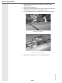
1
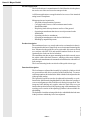
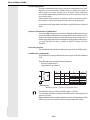
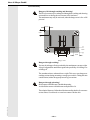
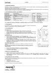
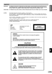
stapleranbaugeräte
forklift truck attachments
équipements hydrauliques
heftruck voorzetapparatuur
Fork Positioner Type 6-25
Operating and Service Instructions
625/02/07-Ver.GB01-GB1
- GB -
625/02/07-Ver.GB01-GB2
Hans H. Meyer GmbH
- GB2 -
Hans H. Meyer GmbH
Titel
Operating and Service Instructions
Product
Fork Positioner
Product type
6-25
Issued by
Hans H. Meyer GmbH
Gittertor 14
D-38259 Salzgitter
Contact
Tel.:
Fax:
+49 (0)5341 803-0
+49 (0)5341 803-196
Mail:
Web:
[email protected]
www.meyer-world.com
Hans H. Meyer Ltd.
Unit 15, Haigh Park,
Whitehill Ind. Est., Reddich,
UK-Stockport SK4 1QR
Tel.:
Fax:
+44 (0)161 4806464
+44(0)161 4804082
Mail:
[email protected]
This document is copyrighted. All rights reserved. This document may
not be copied, duplicated, translated or transformed into an electronic
medium or other machine-readable form, either as a complete document
or as segments of it, without the permission of Hans H. Meyer GmbH.
Subject to change without notice.
… about this Documentation or to the Product may be sent to the
above address.
Further information
… covering other products from Hans H. Meyer can be found on our
Internet page www.meyer-world.com or by phoning us on
+49 (0)5341 803-0 or +44 (0)161 4806464.
625/02/07-Ver.GB01-GB3
Suggestions and tips
- GB3 -
625/02/07-Ver.GB01-GB4
Hans H. Meyer GmbH
- GB4 -
Hans H. Meyer GmbH
625/02/07-Ver.GB01-GB5
List of Contents
Scope of delivery .................................................................................................. 7
Standard accessories ..................................................................................... 7
Optional accessories ..................................................................................... 7
Notice for the reader............................................................................................. 7
Validity .......................................................................................................... 8
Illustrations .................................................................................................... 8
Accentuated text ........................................................................................... 8
Product description ............................................................................................... 9
Product identification ..................................................................................... 9
Intended application .................................................................................... 10
Product description ..................................................................................... 10
Functional description .................................................................................. 10
Possible applications ................................................................................... 11
Operator classification / Qualification ........................................................... 11
Period of operation ..................................................................................... 11
Forklift truck requirements ........................................................................... 11
Safety ................................................................................................................. 12
Qualification of personnel ............................................................................ 12
Global safety ............................................................................................... 12
Personal safety ............................................................................................ 13
Product safety ............................................................................................. 14
Transport and mounting ....................................................................................... 16
Delivery and transport ................................................................................. 16
Packaging ................................................................................................... 16
Unpacking .................................................................................................. 16
Mounting / Installation ......................................................................................... 16
Notice to ecological operation ..................................................................... 16
Mounting and connections to the forklift truck .............................................. 16
Initial operation ................................................................................................... 20
Initial operation ........................................................................................... 20
Pressure settings ................................................................................................. 20
Setting the pressure ..................................................................................... 21
Trail operation..................................................................................................... 23
Conducting a trail ........................................................................................ 23
Preparation for continuous operation ................................................................... 23
Commissioning ............................................................................................ 23
Handling (continuous operation) .......................................................................... 24
Operational pause ............................................................................................... 24
Short pause ................................................................................................. 24
Restarting operations ................................................................................... 24
Decommissioning ................................................................................................ 25
Decommissioning the attachment .................................................................. 25
Removing the attachment from the forklift truck ............................................ 25
Disposal ............................................................................................................. 26
Disposal of the attachment ........................................................................... 26
Maintenance and servicing................................................................................... 26
Preventive measures .................................................................................... 26
Regular inspections before starting work ...................................................... 27
Regular maintenance .................................................................................... 27
- GB5 -
Hans H. Meyer GmbH
625/02/07-Ver.GB01-GB6
Addendum.......................................................................................................... 28
Torque table for bolted fastenings ................................................................ 28
Hydraulic circuits ......................................................................................... 29
For your notes .................................................................................................... 30
- GB6 -
Hans H. Meyer GmbH
Scope of delivery
The Fork Positioner, in future known as the attachment, is delivered
completely assembled and ready for use.
Standard accessories
The attachment is delivered without accessories.
Optional accessories
Optional accessories and spare parts obtainable on request.
625/02/07-Ver.GB01-GB7
Further information covering optional delivered accessories may be found
in the documentation delivered herewith.
- GB7 -
Hans H. Meyer GmbH
Notice for the reader
This document contains information and the code of conduct required
for safely operating this attachment. We advise reading this document
completely before operating the attachment. Keep this document ready
for reference at all times.
In order to operate this attachment effectively, the following aspects are
covered in this document:
- Transportation of the attachment, mounting and trail operation.
- Working with the attachment.
- Maintainance and servicing the attachment.
Validity
This document is valid for:
- the operating company.
- all persons working on or operating this attachment.
Illustrations
Some of the illustrations in this document show the attachment in a
simplified or diagrammatic manner.
Accentuated text
Varying circumstances have been accentuated. Symbols mark important
information. The following examples show the principal accents and
symbols used:
1. Step, an operational sequence.
2. Step, the next operational sequence.
etc.
These are health and safety notices!
Warning notices point out dangers to life and limb or damage that may
occur to the attachment through improper use.
625/02/07-Ver.GB01-GB8
This is an indication of further available information.
Such references are intended to help simplify working with the attachment.
- GB8 -
Hans H. Meyer GmbH
Product description
Product identification
All attachments are clearly marked with a identification label. The
identification label is attached to the front righthand side of the backplate
as seen from the operators driving position.
Identification label
625/02/07-Ver.GB01-GB9
The identification label bears the following information:
- Manufacturer and address
- Warning notice to load capacity
- Year of manufacture
- Type
- Serial number
- Load capacity
- Load centre
- Mass
- Centre of gravity
- Hydraulic operating pressure
- CE-Symbol
- Works number, if applicable
- GB9 -
Hans H. Meyer GmbH
Intended application
The Fork Positioner is an attachment for forklift trucks which replaces
the trucks own forks and is used to transport loads.
A different application or an application far in excess of the intended
rating is not in compliance.
Misappropriate use in particular:
- Any kind of transportation of persons.
- Carrying loads in excess of the maximum stated on the
identification label.
- Displacing loads sideways that are not free of the ground.
- Operating an attachment that is not correctly mounted on the
forklift truck.
- Operating a defective attachment.
- Operating an attachment on a defective forklift truck.
- Handling by unqualified persons.
Product description
The attachment has a very sturdy and torsion-resistant basic chassis.
Incorporated in this basic clamp body are two horizontal chromed guide
bars. Mounted on the guide bars are two ajustable fork carriers which
are conform with ISO 2328 and enables standard forks to be used.
Optionally, the forks can also be bolted on.
The attachment also has an upper mounting hook which extends across
the whole width of the back structure, which provides more ridgidity
and allows the attachment to be mounted on forklift trucks with narrower
fork carriages.
The lower mounting hooks can also be of the quick release type.
625/02/07-Ver.GB01-GB10
Functional description
The load arms are adjusted horizontally by hydraulic cylinders which
are operated from the drivers position on the forklift truck. To ensure
safe transportation, the load must be lifted with the forks adjusted to the
widest possible setting.
The hydraulic load arms can also be adjusted horizontally as a pair,
lateral to the forklift trucks longditudinal axis, this allows the operator to
correct misalignment of the forklift truck during his approach. This
integrated side shifting only applies when the load arms are at an
intermediate position between the opening range of the attachment. The
resulting reserve stroke of the adjusting cylinders is then available for
side shifting.
The hydraulic circuit has an integral lockvalve which holds the load arms
in the position to which they have been adjusted.
- GB10 -
Hans H. Meyer GmbH
Possible applications
This type of attachment may only be used for the transportation of loads
that can to be carried on forks. Suitable loads, are loads to be carried on
pallets, in boxes or crates, in tubs, bins or in frames. These loads must
have suitable load holding facilities such as pockets or must be elevated
to accept the forks.
Other suitable loads are those elevated by chocks or in shelves, such as
bar sections or where the load itself can be entered e.g. large pipes.
It is not allowed to clamp loads of any kind, using only the tips of the load
arms!
Operator classification / Qualification
As an operating company, you must have adequate qualified personnel to
operate forklift truck attachments. Further details to this subject may be
found in the following chapters of this instruction manual. In the case of
not having qualified personnel or furthermore having doubts to this subject,
you may ask Hans H. Meyer GmbH (or Hans H. Meyer Ltd.) for
assistance.
Period of operation
The attachment is designed for uninterupted operation on forklift trucks.
Forklift truck requirements
The forklift truck carriage dimensions must comply to the ISO Standard
2328.
The following values may help for the orientation:
- Reference dimension h3.
- Hydraulic delivery volumes.
A
Clas s
h3
tol.
ISO 2328
mm
mm
2
381
- 1
3
476
- 1,5
4
597
- 1,5
B
C
Type
Hydr.-Vol.
l / min.
6 - 2504
30
± 5
6 - 2506
35
± 10
6 - 2509
40
± 10
6 - 2512
50
± 10
Mounting classes, Truck Carriage ISO 2328
625/02/07-Ver.GB01-GB11
The hydraulic delivery volume should be approx. 30 l/min.
Lower hydraulic delivery volumes will result in slower and irregular load
arm travel speeds.
Higher hydraulic delivery volumes result in excessive oil temperatures which
will cause greater wear and less efficiency in the Hydraulic system.
- GB11 -
Hans H. Meyer GmbH
Safety
Qualification of personnel
All persons either working on or with the attachment must be qualified
to do so.
Operating personnel:
Must have adequate instruction in the functional and operational
sequences.
Knowledge of operational sequences while executing the required work
operations.
Service personnel:
Established knowledge of mechanical engineering, electrotechnology and
hydraulics.
Authorisation to comission the attachment according to the relevant
standards of technical safety.
Established knowledge of the composition and functioning of the
attachment.
As an operator of attachments, it must be ensured that all persons involved
in the mounting, operating, servicing or repairing of attachments have
thoroughly read and understood the relevant parts of the Operating and
Service Instructions.
Global safety
This attachment complies to the current state of science and technology.
It is dependable and safe to operate. Even so, it could still harbour
possible dangers to persons or faults may occur. Attention to the
Operating and Service Instructions is therefore mandatory.
The manufacturer´s Operating and Service Instruction manual is a
conduct of behavior for the operators of attachments and for all persons
involved in the mounting, operating, servicing or repairing of attachments.
625/02/07-Ver.GB01-GB12
Risk of injury through improper application!
Be aware that persons may be at risk through improper use. Furthermore,
damage to the cargo or the attachment may also result from incorrect
handling.
- GB12 -
Hans H. Meyer GmbH
Personal safety
Danger to life through crushing and shearing!
The life of persons may be endangered through the crushing and shearing
actions that occur during the movements of the load arms.
The attachment may only be activated, when the danger zone is free of all
persons!
0 ,5m
0 ,5m
0 ,5m
0 ,5m
Danger zone
Dangers through crushing!
You may be in danger of being crushed by the attachments own net weight.
Always safeguard the attachment against the possibility of it falling over
or falling off.
The attachment has a substantial net weight. This may cause dangerous
crushing actions during mounting or storage proceedures. Taking this into
consideration, initiate the appropriate safety precautions.
Dangers through poisoning!
Skin contact with lubricants is health threatening.
Avoid all skin contact with lubricants and hydraulic oils.
625/02/07-Ver.GB01-GB13
The technical features of all modern lubricants and hydraulic oils can cause
serious illness if swallowed or come into contact with the skin.
- GB13 -
Hans H. Meyer GmbH
Product safety
Damages caused to products and the attachment!
Incorrect handling of the attachment is likely to cause damage to the
product.
Always apply the attachment correctly to the product.
Always use the attachment and its functions, in the correct form and
manner. Note the following instructions:
- Ensure that the attachment is mounted securely to the forklift
truck.
- When ”opening” the attachment, be sure not to shift other loads
sideways.
Loads being forced sideways while opening the load arms
The load arms and attachment are not designed to withstand this kind of
overloading, serios damage may be caused to both.
Loads on the ground, must not be moved sideways with the
“sideshift” function.
Loads being forced sideways while sideshifting
625/02/07-Ver.GB01-GB14
-
- GB14 -
Hans H. Meyer GmbH
-
No loads are to be clamped between the tips of the load arms.
Loads being clamped between the tips of the load arms
-
During transportation, the load must rest against the backrest,
this applies especially to loads that reach the maximum load
capacity of the attachment, this may otherwise cause a change
in load centre which in turn causes the attachment to be
overloaded and the forklift truck may topple forwards.
625/02/07-Ver.GB01-GB15
The load against the fork backs
- GB15 -
Hans H. Meyer GmbH
Transport and mounting
Delivery and transport
The Hans H. Meyer GmbH delivers the attachment on a pallet.
During transportation, the attachment must be either
- on the original pallet.
- securely mounted on the forklift truck.
- hung in appropriate lifting gear, i.e. with ropes or slings.
Packaging
Generally, the attachment is delivered on a suitable transport pallet and
secured with security bands, but without any further packaging.
In some cases, foil packaging may be used to avoid corrosion.
Unpacking
Remove all existing packaging.
Dangers through overturning!
After the removal of all security bands, the attachment is in a free standing
state and could possibly tip over.
- Be sure the pallet with the attachment is on a level surface.
- Support the attachment using lifting gear or similar before
removing the security bands.
- Remove the security bands.
- Dispose of any packaging materials in the approved manner.
- Further steps are to be taken from the following chapters.
Mounting / Installation
Notice to ecological operation
Enviromental pollution through lubricants!
Great attention must be paid in stopping hydraulic oil and lubricants
from polluting the environment.
Mounting and connections to the forklift truck
Personal injury!
Installation work.
625/02/07-Ver.GB01-GB16
Requirements:
- Arrange the pallet with the attachment, so that the forklift truck
can drive behind the back.
- Make sure that the attachment cannot fall over.
- GB16 -
Hans H. Meyer GmbH
Follow the next steps:
1. Apply a lifting rope or sling arround the upper guide bars, or screw
ring bolts into the threaded holes in the top of the attachment frame
to lift the attachment with hooks.
With ring bolts and hooks
With lifting sling
625/02/07-Ver.GB01-GB17
2. Unbolt and remove the lower mounting hooks.
Fixing bolts for the lower mounting hooks
- GB17 -
Hans H. Meyer GmbH
3. Drive the forklift truck centrally behind the hanging attachment
4. Lower the attachment onto the fork carriage of the truck until the
upper mounting hooks have completely closed over the carriage
profile. Be sure that the centre locking pin of the attachment locates
in the central notch of the carriage.
Centre locking pin
Central slot of the fork carriage
625/02/07-Ver.GB01-GB18
5. Refit the lower mounting hooks.
6. Now tighten up the bolts with a torque wrench.
7. Connect the hydraulic jumper hoses to the attachment and make
the to the repective connections to the forklift truck.
- GB18 -
Hans H. Meyer GmbH
Hydraulic jumper hose connections
625/02/07-Ver.GB01-GB19
Connection 1: Load arm adjustment
Connection 2: Side shifting
- GB19 -
Hans H. Meyer GmbH
Initial operation
Initial operation
Follow the next steps:
1. Check the oil level in the forklift truck, as the attachment withdraws
a certain volume of hydraulic oil from the trucks tank.
2. When neccesary, top up the hydraulic oil.
3. Take all functions, that being all cylinders, to the end of their travel.
4. Respectively, keep the hydraulic pressure constant for 10 seconds.
5. Inspect all hydraulic couplings for leakages.
6. When neccesary, retighten any leaking hydraulic couplings.
Pressure settings
The preliminary working pressure neccesary to operate the side shifting
function of the load arms is preset in the factory. The diversity of hydraulic
systems and forklift trucks and the different perfomance rates of these
systems, requires indiviual pressure settings. Ideally, a maximum pressure
of 120 bar should not be overstepped for any of the functions.
This maximum pressure is to set on the forklift truck.
It is not always neccesary to use the maximum hydraulic working
pressure. The pressure settings should in fact be adjusted to suit the
load type, this will guard against damage and prolong the working life of
the attachment.
625/02/07-Ver.GB01-GB20
Valve with cap nut
- GB20 -
Hans H. Meyer GmbH
Setting the pressure
Requirements:
- Prepare a load with the maximum permitted load capacity.
Follow the next steps:
1. Remove the existing cap nuts.
Valve with cap nut removed
2. Slacken off the locknut.
Slackening off the locknut
625/02/07-Ver.GB01-GB21
3. Completely unscrew the adjusting screw (anti-clockwise).
Unscrew the adjusting screw
- GB21 -
Hans H. Meyer GmbH
4. Now lift the maximum load in preparation for setting the side
shifting function
5. Operate the sideshift lever.
6. Slowly turn the adjustment screw for the side shift function clockwise
until the load starts to move at an adaquate speed.
7. Lock the adjustment screw with the locknut and refit the cap nut.
Tightening the locknut
The cap nut has been refitted
625/02/07-Ver.GB01-GB22
8. All pressure settings have now been correctly adjusted.
- GB22 -
Hans H. Meyer GmbH
Trail operation
During the trail operation, the verification of the load bearing capacity is
to be carried out using the maximum load stated on the identification label
of the attachment. However, if the forklift truck rating plate specifies a
lower load carrying capacity, only loads to or below this specification
may be transported!
Conducting a trail
Requirements:
- Choose a suitable load for the trail opertation.
- The load chosen must be of the same type as the load to be
transported during normal daily operations.
Follow the next steps:
1. Opened the load arms to an approriate width to safely lift the load.
2. Lift the load to a height of approx. 10 cm off the floor.
3. Side shift the load to each side and hold the forklift truck lever in its
fully deflected position for approx. 10sec.
4. Inspect all hydraulic elements and connctions for leaks.
5. If all functions work correctly and no leaks are apparent, the attachment
may now be put into operation.
Should the trail be a failure, check the pressure settings or reset them as
required.
If no serviceable result can be obtained, inform the appropriate supervisor
responsible.
Preparation for continuous operation
Commissioning
Regular checks before starting work:
- Inspect the complete hydraulic system for leaks.
- Inspect for damage to hydraulic cylinders and fittings such as
hoses, pipes, valves and connectors.
- Inspect for wear and cracks in the load arms.
- Inspect for deformation of any parts; indication of a possible
accident.
- That the attachment is well seated on the forklift truck and that
the retaining bolts for the upper and lower hooks are screwed
in tightly (see addendum; Torque Table).
625/02/07-Ver.GB01-GB23
If damage is detected:
- By no means is the attachment to be used!
- Inform the appropiate supervisor responsible immediately!
- GB23 -
Hans H. Meyer GmbH
Handling (continuous operation)
The attachment on its own, not attached to a forklift truck, cannot be
activated and can therefore not be operated.
Because of the wide variety of forklift trucks and the differing operating
functions (levers, pedals and switches) etc., it is necessary that the
operating instructions for these functions be taken from the forklift truck
instruction manual.
Danger to life
- Adhere to all safety regulations.
- Pay attention to this instruction manual.
The attachment may only carry loads in relation to its load centre that
do not exceed the maximum load stated on the attachment identification
label.
If reduced load capacities are stated on the rating plate for forklift trucks
with attachments, then these specify the maxmimum loads to be carried.
Suitable load types and their handling can be found in chapter “Product
description”.
In order to avoid further damage occuring after an accident, a trained
person must thoroughly inspect all parts of the basic unit for distortion
and fractures.
Operational pauses
Short pause
A short pause can be defined as switching off the forklift truck to end a
working day or before the start of a work break.
In these or similar cases, follow the instructions in the forklift truck
instruction manual.
Dangers caused by falling or slipping loads!
- No loads may be resting on the load arms while the attachment is
standing idle.
- Observe the instructions in the forklift truck instruction manual.
- Relieve the attachments hydraulic system of pressure (see forklift
truck instruction manual).
625/02/07-Ver.GB01-GB24
Restarting operations
See chapter “Preparation for continuous operation”.
- GB24 -
Hans H. Meyer GmbH
Decommissioning
To decommission an attachment means that the attachment is removed
from the forklift truck for either:
- being refitted at a later date.
- being fitted to a different forklift truck.
Decommissioning the attachment
Requirements:
- a suitable vessel to be at hand to catch escaping hydraulic oil.
- either sawdust or a similar binding agent is at hand to absorb
leaked hydraulic oil.
- a suitable transport pallet is at hand.
Follow the next steps:
1. With the help of a high-pressure cleaner, remove all dirt and the
remains of lubrication from the guide profiles.
2. Leave the attachment to dry in the open air or speed up the
procedure by using compressed air.
3. Apply fresh lubricant to the guide profiles (for suitable lubricants,
see the chapter on ”Maintenance and Servicing”).
4. Take all relevant moving parts through their movements to
disperse the lubricants evenly.
5. Spray all blank metallic parts with a commercial preservative
intended for this purpose.
6. Switch off the forklift truck.
7. Relieve the hydraulic system of pressure (see the instructions in
the forklift truck manual).
Removing the attachment from the forklift truck
625/02/07-Ver.GB01-GB25
Risk of injury through hydraulic oil spillage!
Hydraulic oil may be spilled onto the floor when disconnecting the hoses,
thereby increasing the danger of slipping. Skin contact may cause chemical
burns.
Follow the next steps:
1. Wear your personal protective gear.
2. Disconnect the hydraulic jumper hoses from the forklift truck.
3. Catch any leaking hydraulic oil with an appropriate vessel.
4. Any spilled hydraulic oil must be bound using the appropriate
binding agent and disposed of in accordance to regulations.
5. Remove the bolts from the lower mounting hooks.
6. Secure the attachment with suitable lifting tackle and by tilting the
mast forwards and lowering the fork carriage, reverse the forklift truck
away from under the upper mounting hooks.
7. Lower the attachment onto the transport pallet and safeguard it against
falling over e.g. by tying it down.
8. To safeguard against loss, refit the lower bolts and mounting hooks.
9. Store the attachment in a dry place and cover it using a suitable
covering.
- GB25 -
Hans H. Meyer GmbH
Disposal
After the expiration of the assigned working period or working life has
been reached, the attachment may be decommissioned and scrapped.
Disposal of the attachment
Follow the next steps:
1. Decommission the attachment (see the last chapter).
2. Take appropriate measures to ensure that the attachment is kept
from being used again.
3. Dismantle the attachment professionally.
4. Seperate all individual parts and scrap them according to the
materials used.
5. Dispose of all surplus fluids according to regulations.
Maintenance and servicing
Service and repairs at regular intervals are the vital key to prolonging
the attachments working life.
Breakdown!
Repairs to major functional elements such as hydraulic cylinders and
valves, must only be carried out by persons trained to do so.
Danger to life!
Work on the hydraulic system must only be carried out after first
depressurising the hydraulic circuits.
Escaping jets of high pressure hydraulic oil can cause bad injuries if the
hydraulic circuit is not first depressurised before working on it!
Preventive measures
A higher rate of wear, possibly causing corrosion to the guide profiles,
will result from attachments operating in extremely dirty environments,
this can also have negative effects on other blank metallic surfaces, e.g.
piston rods, causing leaks around the packing seals.
625/02/07-Ver.GB01-GB26
Quite often, dirt collecting on the attachment is caused by the front wheels
of the forklift truck, which throw up dirt and grit from the road surface.
It is therefore advisable to fit the truck with suitable mudguards.
- GB26 -
Hans H. Meyer GmbH
Regular inspections before starting work
The following points must be accounted for before starting work:
- Leakages in hydraulic cylinders, valves and the various other
hydraulic connections.
- Deformation and cracks in the load arms.
- The correct mounting of the attachment on the forklift truck and
especially the fastening bolts for the mounting hooks.
If damage is detected, inform the appropiate supervisor responsible
immediately!
Regular maintenance
Lubrication and maintenance intervals are dependant on the workload of
the application and external influences e.g. the effects of dust and dirt,
fluctuations in temperature change and weather conditions.
Follow the next steps:
1. With the help of a high-pressure cleaner, remove all dirt and the
remains of lubrication from the guide profiles.
2. Leave the attachment to dry in the open air or speed up the
procedure by using compressed air.
3. Inspect the attachment for leaks in hydraulic cylinders, valves
and the various other hydraulic connections.
4. Inspect the load arms, forks and the main frame for deformation and
cracks.
5. Inspect all fastening bolts, if necessary by using a torque-wrench
to check tightness (a torque table can be found in the
addendum).
6. Apply fresh lubricant to the guide profiles.
Be sure to use grease that will not thicken or harden when exposed to
very low temperatures.
Grease recommendations:
- GENERAL-PURPOSE Class 2
7. Take all relevant moving parts through their movements to
disperse the lubricants evenly.
8. Spray all blank metallic parts with a commercial preservative
intended for this purpose.
625/02/07-Ver.GB01-GB27
Always give the type and serial number (see product identification
label) when technical assistance or spare parts are required!
- GB27 -
Hans H. Meyer GmbH
Addendum
Torque table for bolted fastenings
When tightening cylinder and hexagon type bolts, the correct torque
must be obtained by using a torque wrench.
The necessary torque requirements are classified by their sizes and
strengths in the table below.
Old and used bolts must always be replaced by new ones.
Anzie h-Dre hmome nte / torque table / couple s de s e rrage
Ge winde
thre ad
file t
8.8
3,1 N m
6,1 N m
10,4 Nm
25 N m
51 N m
87 N m
140 Nm
215 Nm
300 N m
430 N m
580 N m
740 N m
1100 Nm
15 0 0 N m
4
5
6
8
10
12
14
16
18
20
22
24
27
30
10.9
4,5 N m
8,9 N m
15,5 Nm
37 N m
75 N m
130 Nm
205 N m
310 Nm
430 N m
620 N m
830 N m
1060 Nm
15 5 0 N m
2 10 0 N m
12.9
5,3 N m
10,4 Nm
18 Nm
43 N m
87 N m
150 Nm
240 N m
370 N m
510 Nm
720 N m
970 N m
1240 Nm
1850 Nm
2500 N m
100
--10 Nm
18 Nm
37 N m
80 N m
12 0 N m
-------------
625/02/07-Ver.GB01-GB28
M
M
M
M
M
M
M
M
M
M
M
M
M
M
Für / for / ave c
Schraube n /
bolts / vis
Ve rbus Ripp
Fe s tigke its klas s e
clas s of s tre ngth
Force de ré s is tance
- GB28 -
Hans H. Meyer GmbH
Hydraulic circuits
The reference markings on the hydraulic valve are interpretated as follows:
=
=
=
=
=
open load-arms
close load-arms
side shifting to the left and right
cylinder connections to the piston-head side
cylinder connections to the piston-rod side
625/02/07-Ver.GB01-GB29
A1 + A2
B1 + B2
S1 + S2
ZA1 + ZA2
ZB
- GB29 -
Hans H. Meyer GmbH
625/02/07-Ver.GB01-GB30
For your notes
- GB30 -