1
'"&
!%$
"$
" %
$ ' "# Important User Information
Because of the variety of uses for the products described in this
publication, those responsible for the application and use of this control
equipment must satisfy themselves that all necessary steps have been
taken to assure that each application and use meets all performance and
safety requirements, including any applicable laws, regulations, codes
and standards.
The illustrations, charts, sample programs and layout examples shown in
this guide are intended solely for example. Since there are many
variables and requirements associated with any particular installation,
Allen-Bradley does not assume responsibility or liability (to include
intellectual property liability) for actual use based upon the examples
shown in this publication.
Allen-Bradley publication SGI–1.1, “Safety Guidelines For The
Application, Installation and Maintenance of Solid State Control”
(available from your local Allen-Bradley office) describes some
important differences between solid-state equipment and
electromechanical devices which should be taken into consideration
when applying products such as those described in this publication.
Reproduction of the contents of this copyrighted publication, in whole or
in part, without written permission of Allen–Bradley Company, Inc.
is prohibited.
Throughout this manual we make notes to alert you to possible injury to
people or damage to equipment under specific circumstances.
!
ATTENTION: Identifies information about practices or
circumstances that can lead to personal injury or death,
property damage, or economic loss.
Attention helps you:
• identify a hazard
• avoid the hazard
• recognize the consequences
Important: Identifies information that is especially important for
successful application and understanding of the product.
Important: We recommend you frequently backup your application
programs on appropriate storage medium to avoid possible
data loss.
DeviceNet, DeviceNetManager, and RediSTATION are trademarks of Allen-Bradley Company, Inc.
PLC, PLC–2, PLC–3, and PLC–5 are registered trademarks of Allen-Bradley Company, Inc.
Windows is a trademark of Microsoft.
Microsoft is a registered trademark of Microsoft
IBM is a registered trademark of International Business Machines, Incorporated.
All other brand and product names are trademarks or registered trademarks of their respective companies.
The information contained in this manual pertains to the series B
version of the 1794-ID2 frequency input module.
New Information
Updated Information
This version of this publication contains information on control word
2, for setting the filter function for the counters. This filter
information is contained in chapter 1 and identified in chapters 4
and 5.
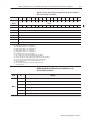
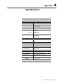
The vibration specifications for this module have been updated. The
specification is as follows:
07,310/(05$. 10',5,104
2(3$5,10$. !(/2(3$563(
513$*( !(/2(3$563(
(.$5,7( 6/,',5:
+1&- 2(3$5,0*
1012(3$5,0*
#,%3$5,10
51 1 51 1 Note: 1 015 &100(&5
/$9,/6/ ,0265 71.5$*( 4,/6.5$0(164.: 51 $..
,02654 ,) 5+( /1'6.( $/%,(05 5(/2(3$563( ,4
(92(&5(' 51 (9&((' 1
51 1 51 1
51 010&10'(04,0* 12(3$5,0*
51 010&10'(04,0* 01012(3$5,0*
* 2($- $&&(.(3$5,10 /4 26.4( 8,'5+
* 2($- $&&(.(3$5,10 /4 26.4( 8,'5+
!(45(' * ; 2(3 <<
6%.,&$5,10 "
$:
soc–ii
Summary of Changes
Preface
Using This Manual
Purpose of this Manual
Audience
This manual shows you how to use your FLEX I/O pulse counter
module with Allen-Bradley programmable controllers. The manual
helps you install, program and troubleshoot your module.
You must be able to program and operate an Allen-Bradley
programmable controller to make efficient use of your FLEX I/O
module. In particular, you must know how to program block
transfers.
We assume that you know how to do this in this manual. If you do
not, refer to the appropriate programming and operations manual
before you attempt to program your modules.
Vocabulary
In this manual, we refer to:
– the pulse counter module as the “input module”
– the Programmable Controller as the “controller”
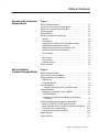
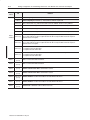
Manual Organization
This manual is divided into seven chapters. The following chart lists
each chapter with its corresponding title and a brief overview of the
topics covered in that chapter.
Chapter
Title
Contents
1
4%04)%5 .& !-$ 2(%
3+1% .3-2%0 .$3+%
%1#0)"%1 /3+1% #.3-2%0 ,.$3+%1 &%!230%1 !-$
(.5 2(%7 &3-#2).-
2
.5 2. -12!++ .30 3+1% .3-2%0
.$3+%
.5 2. )-12!++ !-$ 5)0% 2(% ,.$3+%
3
.$3+% 0.'0!,,)-'
6/+!)-1 "+.#* 20!-1&%0 /0.'0!,,)-' 1!,/+% /0.'0!,1
4
0)2)-' .-&)'30!2).- 2. !-$
%!$)-' 2!231 0., 5)2( !
%,.2% $!/2%0
6/+!)-1 (.5 2. #.-&)'30% 7.30 ,.$3+%1 !-$ 0%!$ 12!231
)-&.0,!2).- &0., 7.30 ,.$3+%1 5(%- 31)-' ! 0%,.2% !$!/2%0
5
.5 .,,3-)#!2).- !*%1 +!#%
!-$ ,!'% !"+% !//)-'
5)2( 2(% %4)#%%2 $!/2%0
6/+!)-1 (.5 7.3 #.,,3-)#!2% 5)2( 7.30 ,.$3+%1 !-$
(.5 2(% ),!'% )1 ,!//%$ 5(%- 31)-' ! %4)#%%2
!$!/2%0
6
-/32 32/32 !-$ .-&)'30!2).&)+%1 &.0 -!+.' .$3+%1 31)-'
.-20.+%2
6/+!)-1 (.5 7.3 #.,,3-)#!2% 5)2( 7.30 ,.$3+%1 !-$
(.5 2(% !-$ #.-&)'30!2).- &)+%1 !0% ,!//%$ 5(%- 31)-'
! .-20.+%2 !$!/2%0
7
!+)"0!2)-' .30 3+1% .3-2%0
.$3+%
.5 2. #!+)"0!2% 2(% ,.$3+%
8
0.3"+%1(..2 .30 3+1% .3-2%0
.$3+%
.5 2. 31% 2(% )-$)#!2.01 2. 20.3"+%1(..2 7.30 ,.$3+%
3"+)#!2).- 8
!7 P–2
Using This Manual
Appendix
A
Title
.$"(%(" 1(-,0
Conventions
Contents
.$"(%(" 1(-,0 %-/ 1'$ .2*0$ "-2,1$/ +-#2*$
We use these conventions in this manual:
In this manual, we show:
Like this:
1' 1 1'$/$ (0 +-/$ (,%-/+ 1(-, !-21 1-.("
(, ,-1'$/ "' .1$/ (, 1'(0 + ,2 *
1' 1 1'$/$ (0 +-/$ (,%-/+ 1(-, !-21 1'$
1-.(" (, ,-1'$/ + ,2 *
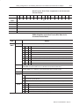
For Additional Information
More
For additional information on FLEX I/O systems and modules, refer
to the following documents:
Catalog
Number
Publications
Voltage
Description
Installation
Instructions
/-#2"1 1
5
5
#"
-,1/-*$1 # .1$/
5
5
#"
$#2,# ,1 $#( -,1/-*$1 # .1$/
5
5
#"
-,1/-*$1 # .1$/
5
5
#"
$#2,# ,1 $#( -,1/-*$1 # .1$/
5
5
#"
$3("$$1 # .1$/
5
User
Manual
5
5
#"
$+-1$ # .1$/
5
5
5
#"
5*-1 $+-1$ # .1$/
5
5
5
#"
/-%(!20 # .1$/
5
5
5
#"
(,) ,.21 -#2*$
5
5
#"
-2/"$ 21.21 -#2*$
5
5
#"
(,) ,.21 -#2*$
5
5
#"
-2/"$ 21.21 -#2*$
5
5
#"
-2/"$ ,.21 -#2*$
5
5
#"
(,) 21.21 -#2*$
5
5
#"
*$"1/-,(" **4 20$# 21.21 -#2*$
5
5
#"
$,0-/ ,.21 -#2*$
5
5
#"
,.21 21.21 -#2*$
5
5
#"
$*$"1 !*$ , *-& ,.21 -#2*$
5
5
#"
$*$"1 !*$ , *-& 21.21 -#2*$
5
Table continued on next page
2!*(" 1(-, 5
4 5 5
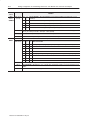
Using This Manual
Catalog
Number
Voltage
9
#
" '&
9
Publications
Description
Installation
Instructions
User
Manual
.054 54054 .$,/) /'5,(
9
9
" '&
54054 3/,$4(' .$,/) /'5,(
9
9
" '&
.054 3/,$4(' .$,/) /'5,(
9
9#
" '&
.054 54054 3/,$4(' .$,/) /'5,(
9
9
" '&
.054 .$,/) /'5,(
9
9
9 " '&
*(2-/&/50,( .054 /'5,(
9
9
9 " '&
*(2-/&/50,( .054 /'5,(
9
9
9
" '&
2(15(.&8 .054 /'5,(
9
9
9
" $&
.054 /'5,(
9
9
" $&
54054 /'5,(
9
9 9 96+2( (2-+.$, $3(
96+2( (2-+.$, $3(
9
9 (2-+.$, $3( !.+4
9
9 53(' (2-+.$, $3( !.+4
(-0(2$452( (2-+.$, $3( !.+4
9
9 02+.) ,$-0 (2-+.$, $3( !.+4
9
9 02+.) ,$-0 (-0(2$452( $3( !.+4
9
(2-+.$, $3( !.+4
9 9 9
9
9
" '&
9
9
9 9 Summary
P–3
9
02+.) ,$-0 (2-+.$, $3( !.+4
9
74(.'(2 $%,(3
9
/5.4+.) +4
9
/6(2 500,8
9
This preface gave you information on how to use this manual
efficiently. The next chapter introduces you to the frequency
module.
5%,+&$4+/. 9! $8 P–4
Using This Manual
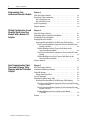
Table of Contents
Overview of the Incremental
Encoder Module
Chapter 1
How to Install Your
Incremental Encoder Module
Chapter 2
$-&7 !-.6 -&37*5 217&.16 2: %28 "6* 7-* 1(5*0*17&/ 1(2)*5 2)8/* $-&7 7-* 1(5*0*17&/ 1(2)*5 2)8/* 2*6 !<3.(&/ 33/.(&7.216 1387 &3&'./.7.*6 2: 7-* 1(5*0*17&/ 1(2)*5 3*5&7*6 #&5.&'/*6 7&57 2817.1, */*(7.1, 7-* .1(5*0*17&/ *1(2)*5 &1) 83)2:1 (2817.1, "32:1 2817.1, 21752//*) '< 1387 "32:1 2817.1, 86.1, 8/6*6 &7 13876 &1) 2817 8/6*6 +520 1(5*0*17&/ 1(2)*56 5*6*7 81(7.21 &7* 81(7.21 725* 81(7.21 .0.7&7.21 81(7.21 -&37*5 800&5< $-&7 !-.6 -&37*5 217&.16 *+25* %28 167&// %285 1387 2)8/* 8523*&1 "1.21 .5*(7.9* 203/.&1(* .5*(7.9* 2: #2/7&,* .5*(7.9* 2:*5 *48.5*0*176 $.5.1, 7-* !*50.1&/ &6* "1.76 =!
6-2:1 167&//.1, 7-* 2)8/* 2817.1, 7-* !*50.1&/ &6* "1.7 21 & &./ &1*/$&// 2817.1, 2817.1, 7-* 1(5*0*17&/ 1(2)*5 2)8/* 21 7-* !*50.1&/
&6* "1.7 211*(7.1, $.5.1, +25 %285 .1(5*0*17&/ *1(2)*5 2)8/* $.5.1, 72 & =! 25 =! !*50.1&/ &6* "1.7 $.5.1, (211*(7.216 +25 7-* .1(5*0*17&/ *1(2)*5 2)8/*
;&03/* 2+ 8/6* !5&160.77*5 $.5.1, ;&03/* 2+ 1(5*0*17&/ 1(2)*5 $.5.1, 2)8/* 1).(&7256 -&37*5 800&5< 8'/.(&7.21 =" &< ii
Table of Contents
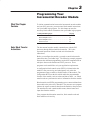
Programming Your
Incremental Encoder Module
Chapter 3
Writing Configuration to and
Reading Status from Your
Module with a Remote I/O
Adapter
Chapter 4
How Communication Takes
Place and I/O Image Table
Mapping with the DeviceNet
Adapter
Chapter 5
4#,*$"3*/. 8 "7 )"3 )*2 )"03&1 /.3"*.2 .3&1 ,/$+ 1".2'&1 .2314$3*/.2 8 "-*,7 1/$&22/1 8 "-*,7 1/$&22/1 8 1/(1"--*.( )"03&1 4--"17 )"3 )*2 )"03&1 /.3"*.2 /.'*(41*.( !/41 .$1&-&.3", .$/%&1 /%4,& &"%*.( "3" 1/- !/41 /%4,& "00*.( "3" '/1 3)& /%4,& .$1&-&.3", .$/%&1 /%4,& 8 -"(& "#,& "00*.( ,/$+ 1".2'&1 &"% /1% 22*(.-&.32 '/1 3)& .$1&-&.3", .$/%&1
/%4,& 8 *3 /1% &'*.*3*/.2 '/1 ,/$+ 1".2'&1 &"% /1%2 '/1 3)&
.$1&-&.3", .$/%&1 /%4,& ,/$+ 1".2'&1 1*3& /1% 22*(.-&.32 '/1 3)& .$1&-&.3", .$/%&1
/%4,& *3 /1% &'*.*3*/.2 '/1 3)& ,/$+ 1".2'&1 1*3& /1%2 '/1 3)&
.$1&-&.3", .$/%&1 /%4,& )"03&1 4--"17 )"3 )*2 )"03&1 /.3"*.2 #/43 &5*$&&3"."(&1 /'36"1& /,,&% 314$341& %"03&1 .043 3"342 /1% 723&- )1/4()043 "00*.( "3" *.3/ 3)& -"(& "#,& .$1&-&.3", .$/%&1 /%4,& 8 -"(& "#,& "00*.( ,/$+ 1".2'&1 &"% /1% 22*(.-&.32 '/1 3)& .$1&-&.3", .$/%&1
/%4,& 8 ,/$+ 1".2'&1 1*3& /1% 22*(.-&.32 '/1 3)& .$1&-&.3", .$/%&1
/%4,& 8 *3 /1% &'*.*3*/.2 '/1 3)& *.$1&-&.3", &.$/%&1 /%4,&
&'"4,32 iii
Table of Contents
Input, Output and
Configuration Files for
Analog Modules when used
with ControlNet
Chapter 6
*#25'3 $,'%5+7'4 $165 5*' 10531.'5 '3 %*'&6.'& #5#:3#04('3 04%*'&6.'& #5#:3#04('3 1&6.' #22+0) 536%563' '3 0265 5#564 !13& #(' 5#5' #5# '7+%' %5+104 1//60+%#5+10 #6.5 '*#7+13 &.' 5#5' '*#7+13 0265 #5# '*#7+13 6210 1&6.' '/17#. 0%3'/'05#. 0%1&'3 1&6.' :
/#)' #$.' #22+0) +5!13& '(+0+5+104 (13 .1%- 3#04('3 '#& !13&4 (13 5*'
6.4' 1605'3 1&6.' Calibrating Your Incremental
Encoder Module
Chapter 7
Troubleshoot the
Incremental Encoder Module
Chapter 8
Specifications
Appendix A
*#25'3 $,'%5+7' #.+$3#5+0) "163 1&6.' #.+$3#5+10 '5*1& #.+$3#5+10 '5*1& !*#5 *+4 *#25'3 105#+04 5#564 0&+%#5134 !*#54 '85 2'%+(+%#5+104 6$.+%#5+10 : #9 Table of Contents
Overview of the Incremental
Encoder Module
What This Chapter
Contains
How You Use the
incremental encoder
Module
Read this chapter to familiarize yourself with the 1794–ID2 module.
For information on
See page
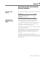
#) #( & ' "%!"' "#% #( ' ' "%!"' "#% #( #& "$(' $ '& #) ' "%!"' "#% $%'& The 1794–ID2 module is an intelligent I/O module designed to
perform high speed pulse counting. The module provides:
• 2 pulse transmitter interfaces, each with 4 optocoupled inputs
Each input has + and – inputs for connection to transmitters with
complementary and noncomplementary signals.
The pulse inputs can accept frequencies up to 100KHz. The module
accepts and returns binary data.
The module’s primary use is accurate, high-speed counting of pulse
from pulse transmitters or incremental encoders with 1 or 2 pulse
trains. This includes quantity counting, positioning and speed
calculations.
The module has 2 up/down counters, each individually
programmable. The number of edges to be counted can be multiplied
by 1, 2 or 4 (x1, x2, x4). Pulse transmitters can be complementary or
noncomplementary.
( '#" + * 1–2
Overview of the Incremental Encoder Module
%($$)%"&'
&'( !'(&
!#"!'(&
+
&'( !'(&
Z+
Z-
$!
( !'(&
A+
A-
+
$)#(& !'(&
B+
BZ+
ZG+
G-
$#(&$" $&
Internal +5V dc
What the Incremental
Encoder Module Does
B+
B-
G+
G-
$#(&$" $&
!#"!'(&
)'#(&
&!")'
( !'(&
$!
$)#(& !'(&
A+
A-
*#!""+ '$"(
$#*&(&
12-24V dc
0V
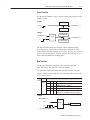
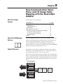
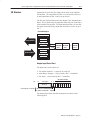
The incremental encoder module performs high-speed scaling
calculation operations for various industrial applications. The
module interfaces with a FLEX family adapter which then
communicates with a programmable controller processor that has
block-transfer capability and external I/O devices.
The adapter/power supply transfers data to the module (block
transfer write) and from the module (block transfer read) using BTW
and BTR instructions in your ladder diagram program. These
instructions let the adapter read input values and status from the
module, and let you write output values and configure the module’s
mode of operation. The following illustration describes the
communication process.
)"!(!$# , + Overview of the Incremental Encoder Module
1–3
!-* &)&37*5 75&16+*56 <285 (21+.,85&7.21 )&7&
72 7-* 02)8/* 86.1, & !$
;7*51&/ )*9.(*6 75&160.7
+5*48*1(< 6.,1&/6 72 7-* 02)8/*
/*;'86
! 1
!
!#
"!
"!
#
$ "%
!
= %285 /&))*5 352,5&0 .16758(76 7-*
&)&37*5 72 3*5+250 & ! 2+ 7-* 9&/8*6
&1) 6725*6 7-*0 .1 & )&7& 7&'/*
!-* 02)8/* (219*576
+5*48*1(< 6.,1&/6 .172 .17*,*5
+250&7 &1) 6725*6 7-*6* 9&/8*6
817./ 7-* &)&37*5 5*48*676 7-*.5
75&16+*5
!-* &)&37*5 &1) 02)8/* )*7*50.1*
7-&7 7-* 75&16+*5 :&6 0&)* :.7-287 *5525
&1) .1387 9&/8*6 &5* :.7-.1 63*(.+.*)
5&1,*
%285 /&))*5 352,5&0 (&1 86* &1)25 029* 7-* )&7& .+ 9&/.)
'*+25* .7 .6 :5.77*1 29*5 '< 7-* 75&16+*5 2+ 1*: )&7& .1 &
68'6*48*17 75&16+*5
%285 /&))*5 352,5&0 3*5+2506 !$6 72 7-* 02)8/* :-*1 <28 32:*5
.7 83 &1) &1< 7.0* <28 :.6- 72 5*(21+.,85* 7-* 02)8/*
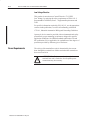
Typical Applications
You can use the 1794–ID2 module in the power management,
automotive, food and beverage, and oil and gas industries for various
flow and/or turbine metering applications. Some sample
applications include:
•
•
•
•
Input Capabilities
turbine shaft speed monitoring
automotive paint booths
brewery flow monitoring
petrochemical flow and custody transfer
The incremental encoder module has 2 identical input channels.
Each of the input channels may accept these input signals:
•
•
•
•
A+ and A–
B+ and B–
Z+ and Z–
G+ and G–
The pulse inputs can accept frequencies up to 100KHz. The module
accepts and returns binary data.
8'/.(&7.21 =" &< 1–4
Overview of the Incremental Encoder Module
How the incremental
encoder Operates
The counter module handles up/down counting and detection of
selectable number of edges (X1, X2, X4) for incremental encoders
with 2 pulse trains, nominal 90o out of phase. The minimum stable
input condition is 2µs.The following paragraphs detail operation of
the incremental encoder module.
Each of the 2 counters has a 16–bit counter register, a preset register
and a latch register.
Variables
Communication between the counter module and the control system
uses variables accessible in the control system program. These
variables include:
• a counter register (Counter)
• a preset register (PresetValue)
• a latch register (LatchValue).
Signal registers and control words are used to set parameters for the
counter configuration. The control word sent to the incremental
encoder module can be read back to the control system, allowing
verification that one I/O scan been performed since the cycle has
been initiated.
Start Counting
The control bit CounterEnable enables counting. It must be set to 1
to enable counting and all other functions.
Selecting the incremental encoder and up/down counting
Depending on the incremental encoder, the module can be set in
different counter modes. The parameter is set using a 3 digit code in
write word 1 or 2 (depending on the channel) control word.
Mode Selection
"*
+#"*"&% / . & #*"&% "*)
&+%*"% &% '&)"*", (")"% & "%'+* )" %# '-%
&+%*"% *($"% . +(*+( %&( +(*+( %&( +(*+( %&( &+%*"% +' &% *! '&)"*", & "%'+* )" %# % &-%
&% '&)"*", & "%'+* )" %# & &+%* +%*"&%
& &+%* +%*"&%
& &+%* +%*"&%
Overview of the Incremental Encoder Module
1–5
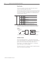
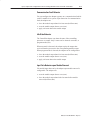
Up/Down Counting Controlled by B Input
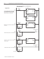
Pulse Counting (Mode 000)
Up/Down counting controlled by input B
%$'!(!* $ ( %)"'' & $)#( ( !#%)( !#%)( ( $)#(& $)#(' )% ! ( $)#(& $)#(' $+#
Counter Mode = 0
Logic
Counter Register
A
%$+#
B = 0/1
Input A
Input B
0
Counter Value
1
2
Counting Up
3
2
1
Counting Down
Up/Down Counting using Pulses at Inputs A and B
Pulse Counting Mode (100)
Up/Down Counting using pulses at the inputs of A and B
$)#(& $)#(' )% $# ( %$'!(!* $ ( %)"'' ( !#%)( # $)#(' $+# $# ( %$'!(!* $ !#%)( Counter Mode = 4
Counter Register
Logic
A
%$+#
B
Input A
Input B
0
Counter Value
1
0
1
2
1
)"!(!$# -
, 1–6
Overview of the Incremental Encoder Module
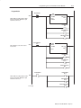
Count Pulses from Incremental Encoders
Up/Down Counting using pulses at the inputs of A and B
Pulse Counting Mode (001, 010. 011)
',&+)%' ') +"& ') !* ' +" (,$* +)#& -#$$ ',&+ " ',&+
#)+#'& ,('-& #* +)%#& . +" ("* # )& ' +" #&(,+ *#!&$* & Counter Mode = 1, 2 or 3
Logic
Counter Register
A
('-&
B
Example 1 - Counter Mode = 1 (x1)
Input A
Input B
Counter Value
1
2
Counting Up
3
2
1
Counting Down
0
3
4
Counting Up
5
4
3
2
1
Counting Down
0
Example 2 - Counter Mode = 2 (x2)
Input A
Input B
Counter Value
1
2
Example 3 - Counter Mode = 3 (x4)
Input A
Input B
Counter Value
,$#+#'& / . 1 2 3 4 5 6 7 8 9
Counting Up
8 7 6 5 4 3 2 1 0
Counting Down
Overview of the Incremental Encoder Module
1–7
Preset Function
Use the preset function to copy a value from the preset register to the
counter register.
Method 1
+","- "$&,-"+
).(-"+ "$&,-"+
Method 2
+","- "$&,-"+
)$&
).(-"+ "$&,-"+
The flag PresetReached is set when the counter register and the
preset register are equal (if the counter preset is reached, or if the
counter has been loaded with the preset value). This flag is reset on a
positive edge of PresetReset after the operation and can only be set
after at least one additional counting pulse.
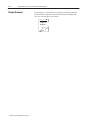
Gate Function
Use the gate function to determine when counting starts and
stops.You can use this function to measure distance.
The parameter GateControl determines the gate function. The gate
signal is connected to input G. It is a 2–bit binary code in write word
1 or 2, bits 09 and 10
)+!
)+ Gate Control Function
&-, &(+0 -" )(-+)' &-,
) $-" #.( -&)( )( &(*.- ).(- &, &(!"*"(!"(-
).(-&($ )('0 &# -&/"
).(-&($ )('0 &# &( -&/"
'&+-&)( &# (! '' )-%"+ )(!&-&)(, +"
#.'#&''"! +"#"+ -) '&+-&($ -%" )!.'" %*-"+ Example
Gate Control = 1
G=1
Logic
Counter Register
A
%" ).(-"+ &, ).(-&($ &# .'& -&)( 1 0 1–8
Overview of the Incremental Encoder Module
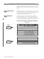
Store Function
Use the store function to copy the value in the counter register
(Counter) to the latch register (StoreValue).
The StoreControl parameter determines the store function. Execution
occurs on either the positive or negative edge of input signals G and
Z respectively (see table). The parameter is a 2–bit binary code in
write word 1 (bits 11 and 12)
')
') $+*
$&). +') '&+)'% $+*
- +# ',&+ ) -%, '& +# ('*$+$$! +') " '! - +# ',&+ ) -%, '& +# ('*$+$$! +') " '! - +# ',&+ ) -%, '& +# & "+$$! +') - +# ',&+ ) -%, '& '+# +# ('*$+$& & "+$- " '! $! +') " '! "
The parameter Stored must be reset (0). Stored is set (1) when the
operation is completed. Reset after the operation with StoreReset.
Example
Store Control = 1
Stored = 0
G
Counter Register
Logic
Latched = 1
Store Register
# ',&+ ) -%, $* '($ +' +# *+') ) "$*+ ) '& +# ('*$+$-
" '! $&(,+ *$"&% Limitation Function
If the control bit RangeLimited = 1, the counter counts up to the
preset value and restarts at 0. Counting down, the counter reaches the
preset value on the next pulse if the current counter value = 0.
RangeLimited = 0 corresponds to RangeLimited = 1 if the preset
value = FFFF in hex = 65535 in decimal.
The flag PresetReached is set when the counter is equal to the preset
value. Use PresetReset to reset the flag.
,%$+$'& / . Overview of the Incremental Encoder Module
1–9
Count Up pulse (+)
%- (!#
(-',* *+,%-
(-',* !#+,*
Count Down pulse (-)
*+, !#+,*
(-',* (!#
(-',* !#+,*
Note: ," )*+, *!#+,* .%- ," (-',* *,#'+ ," .%- Filter Function
The filter function is only valid during mode 000 (pulse counting).
You enable the filter function by setting bits in Control word 2. Each
counter can be individually filtered by enabling its associated filter
control bit. However the filter is common to both counters.
When a counter is in mode 000 and its filter is enabled, signal A is
internally sampled at a rate 8 times higher than the filter constant. A
change of state in A has to be valid during 4 samples before it
reaches the counter.
-,)-, *(& #%,*
&)% %($
',*'% (-',*
0 1 2
3
0 1 2 3
0 1 2
3
-%#,#(' 0 / 1–10
Overview of the Incremental Encoder Module
Chapter Summary
In this chapter, you learned about the incremental encoder module,
block transfer communication, and details of how the module
functions. Now you can install the module.
How to Install Your
Incremental Encoder Module
What This Chapter
Contains
Before You Install Your
Input Module
In this chapter, we tell you about:
For information on
See page
!"*-! *0 )./'' *0- * 0'! 0-*+!) )%*) %-!/%1!. *2!- !,0%-!(!)/. )./''%)# /$! * 0'! *) -%' *) 2''+)!' *) /$! /!-(%)' .! *))!/%)# %-%)# * 0'! ) %/*-. Before installing your incremental encoder module in the FLEX I/O
system:
You need to:
As described under:
'0'/! /$! +*2!- -!,0%-!(!)/. *" ''
(* 0'!. %) !$ .3./!(
*2!- !,0%-!(!)/. +#! 4
*.%/%*) /$! &!3.2%/$ *) /$! /!-(%)' .!
)./''%)# /$! * 0'! +#! !
European Union Directive
Compliance
ATTENTION: The incremental encoder module does
not receive power from the backplane. +24V dc power
must be applied to your module before installation. If
power is not applied, the module position will appear
to the adapter as an empty slot in your chassis.
If this product has the CE mark it is approved for installation within
the European Union and EEA regions. It has been designed and
tested to meet the following directives.
EMC Directive
This product is tested to meet Council Directive 89/336/EEC
Electromagnetic Compatibility (EMC) and the following standards,
in whole or in part, documented in a technical construction file:
• EN 50081-2EMC – Generic Emission Standard, Part 2 –
Industrial Environment
• EN 50082-2EMC – Generic Immunity Standard, Part 2 –
Industrial Environment
This product is intended for use in an industrial environment.
0'%/%*) 4
3 2–2
How to Install Your Incremental Encoder Module
Low Voltage Directive
This product is tested to meet Council Directive 73/23/EEC
Low Voltage, by applying the safety requirements of EN 61131–2
Programmable Controllers, Part 2 – Equipment Requirements and
Tests.
For specific information required by EN 61131-2, see the appropriate
sections in this publication, as well as Allen-Bradley publication
1770-4.1, Industrial Automation Wiring and Grounding Guidelines.
Open style devices must be provided with environmental and safety
protection by proper mounting in enclosures designed for specific
application conditions. See NEMA Standards publication 250 and
IEC publication 529, as applicable, for explanations of the degrees of
protection provided by different types of enclosure.
Power Requirements
The wiring of the terminal base unit is determined by the current
draw through the terminal base. Make certain that the current draw
does not exceed 10A.
!
ATTENTION: Total current draw through the
terminal base unit is limited to 10A. Separate power
connections may be necessary.
How to Install Your Incremental Encoder Module
2–3
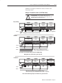
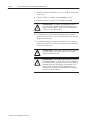
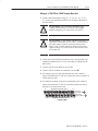
Methods of wiring the terminal base units are shown in the
illustration below.
Wiring the Terminal Base Units (1794ĆTB3G shown)
!
ATTENTION: Do not daisy chain power or
ground from the terminal base unit to any ac or dc
digital module terminal base unit.
DaisyĆchaining
$'+ & '-% '( +
(.%
$'+ & '-% '( +
(.%
&
(.%
$'+ & '-% '( +
(.%
Note: %% &(.% , &.,- ).%, !+ *. '0 (+ & &(.% , !(+ -#$, ('!$".+-$('
Wiring when total current draw is less than 10A
Individual
$"$-% ').(.%
$'+ & '-% '( +
(.%
$"$-% ').(.%
$"$-% .-).(.%
Note: , -#$, ('!$".+-$(' $! .,$'" '0
1'($,0 $"$-% &(.% , $' 0(.+ ,0,- &
incremental encoder Module wiring separate from digital wiring.
Wiring when total current draw is greater than 10A
Combination
$'+ & '-% '( +
(.%
$'+ & '-% '( +
(.%
&
(.%
$'+ & '-% '( +
(.%
Note: %% &(.% , )(/ + 0 -# ,& )(/ + ,.))%0
&.,- ).%, !+ *. '0 (+ & &(.% , !(+ -#$, ('!$".+-$('
Total current draw through any base unit must not be greater than 10A
.%$-$(' 2 0 2–4
How to Install Your Incremental Encoder Module
Installing the Module
Installation of the incremental encoder module consists of:
• mounting the terminal base unit
• installing the module into the terminal base unit
• installing the connecting wiring to the terminal base unit
If you are installing your module into a terminal base unit that is
already installed, proceed to “Mounting the incremental encoder
Module on the Terminal Base” on page 2–7.
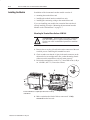
Mounting the Terminal Base Unit on a DIN Rail
!
ATTENTION: Do not remove or replace a terminal
base unit when power is applied. Interruption of the
flexbus can result in unintended operation or machine
motion.
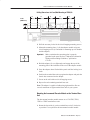
1. Remove the cover plug (if used) in the male connector of the unit
to which you are connecting this terminal base unit.
2. Check to make sure that the 16 pins in the male connector on the
adjacent device are straight and in line so that the mating female
connector on this terminal base unit will mate correctly.
3. Position the terminal base on the 35 x 7.5mm DIN rail A (A-B pt.
no. 199-DR1; 46277-3). Proceed as follows:
C
A
B
A
#$ $" # $ #$ &" $ $ !
$ "
4. Make certain that the female flexbus connector C is fully
retracted into the base unit.
%$ ( ' How to Install Your Incremental Encoder Module
2–5
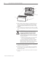
& &$ ! % '!& "($ && !%& & #&$
%'$ & "" "! & &$ ! % %% '!$ & " &
#&$ ! & *'% "!!&"$ % '+ $&$&
$%% ")! "! & &$ ! % '!& &" " & &$ ! % "! &
$ & &$ ! % "% !"& " !&" # '% %$)$($
"$ % $ ( &" "#! & "! & #$%% ")! "! & &$ !
% '!& '% )& & $ ! $% & "! & &" " &
% ! #
30077–M
#'% & *'% "!!&"$ !&" & %
" & #&$ &" " #& & #! "!!&"!
'&"! , + 2–6
How to Install Your Incremental Encoder Module
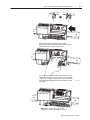
5. Repeat the above steps to install the next terminal base.
Panel/Wall Mounting
Installation on a wall or panel consists of:
•
•
•
•
laying out the drilling points on the wall or panel
drilling the pilot holes for the mounting screws
mounting the adapter mounting plate
installing the terminal base units and securing them to the wall or
panel
If you are installing your module into a terminal base unit that is
already installed, proceed to “Mounting the incremental encoder
Module on the Terminal Base” on page2–7.
Use the mounting kit Cat. No. 1794-NM1 for panel/wall mounting.
1794ĆNM1 Mounting Kit
(', ',+
(-',$'" %, !(* ), *
+ %!0,))$'" +* .+
!(* ,# ), * ' # !(* -) ,( &(-% +
), * (-%
'(, $'%- *&$'% + '$,
'(, $'%- To install the mounting plate on a wall or panel:
1. Lay out the required points on the wall/panel as shown in the
drilling dimension drawing.
-%$,$(' 0 / How to Install Your Incremental Encoder Module
2–7
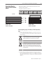
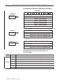
Drilling Dimensions for Panel/Wall Mounting of FLEX I/O
Inches
(Millimeters)
2. Drill the necessary holes for the #6 self-tapping mounting screws.
3. Mount the mounting plate (1) for the adapter module using two
#6 self-tapping screws (18 included for mounting up to 8 modules
and the adapter).
Important:
More
Make certain that the mounting plate is properly
grounded to the panel. Refer to “Industrial Automation
Wiring and Grounding Guidelines,” publication
1770-4.1.
4. Hold the adapter (2) at a slight angle and engage the top of the
mounting plate in the indention on the rear of the adapter module.
5. Press the adapter down flush with the panel until the locking lever
locks.
6. Position the terminal base unit up against the adapter and push the
female bus connector into the adapter.
7. Secure to the wall with two #6 self-tapping screws.
8. Repeat for each remaining terminal base unit.
Note: The adapter is capable of addressing eight modules. Do not
exceed a maximum of eight terminal base units in your system.
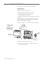
Mounting the Incremental Encoder Module on the Terminal Base
Unit
The incremental encoder module mounts on a 1794-TB3, TB3S,
-TBN or -TBNF terminal base unit.
1. Rotate the keyswitch (1) on the terminal base unit (2) clockwise
to position 1 as required for the incremental encoder module.
2–8
How to Install Your Incremental Encoder Module
2. Make certain the flexbus connector (3) is pushed all the way to
the left to connect with the neighboring terminal base/adapter.
You cannot install the module unless the connector is fully
extended.
3. Make sure that the pins on the bottom of the module are straight
so they will align properly with the connector in the terminal base
unit.
!
ATTENTION: Remove field-side power before
removing or inserting the module. This module is
designed so you can remove and insert it under
backplane power. When you remove or insert a
module with field-side power applied, an electrical arc
may occur. An electrical arc can cause personal injury
or property damage by:
• sending an erroneous signal to your system’s field
devices causing unintended machine motion
• causing an explosion in a hazardous environment
Repeated electrical arcing causes excessive wear to
contacts on both the module and its mating connector.
Worn contacts may create electrical resistance.
4. Position the module (4) with its alignment bar (5) aligned with
the groove (6) on the terminal base.
5. Press firmly and evenly to seat the module in the terminal base
unit. The module is seated when the latching mechanism (7) is
locked into the module.
6. Repeat the above steps to install the next module in its terminal
base unit.
How to Install Your Incremental Encoder Module
Connecting Wiring for
Your incremental encoder
Module
2–9
Wiring to the module is made through the terminal base unit on
which the module mounts.
Compatible terminal base units are:
Module
1794ĆTB3
1794ĆTB3S
1794ĆTBN
1794ĆTBNF
1794-ID2
Yes
Yes
Yes
Yes
1794ĆTB3
1794ĆTB3S
0 1 2 3 4 5 6 7 8 9 10 11 12 13 14 15
16 17 18 19 20 21 22 23 24 25 26 27 28 29 30 31 32 33
34 35 36 37 38 39 40 41 42 43 44 45 46 47 48 49 50 51
0
1 2 3 4 5
6 7
8 9 10 11 12 13 14 15
A
0 -15
A
B
16-33
B
C
34-51
C
16 17 18 19 20 21 22 23 24 25 26 27 28 29 30 31 32 33
34 35 36 37 38 39 40 41 42 43 44 45 46 47 48 49 50 51
# & &"# " ($! $
! ! " "!
! %%% $"'!
&$' %%% $"'!
! ! " "!
! %%% $"'!
&$' %%% $"'!
Connecting Wiring using a 1794ĆTB3 and ĆTB3S Terminal Base
Units
1. Connect individual input wiring (A+, A–, B+, B–, Z+, Z–, G+,
G–) to numbered terminals on the 0–15 row (A) as indicated in
the table below.
!
!
ATTENTION: Do not connect maximum input
voltage simultaneously to all inputs if the module
ambient temperature is expected to exceed 40oC.
ATTENTION: If the module ambient temperature is
expected to continuously exceed 40oC, you must limit
the input voltage using an external resistor on each
input. A 1KΩ resistor effectively limits a 24V sensor
signal to about 15V at the input. Do not limit the input
to less than 6V.
2. Connect the associated input common (3-wire devices only) to
the corresponding terminal on the 16-33 row (B) for each input as
indicated in the table below. (Commons are internally connected
together.)
'&"! * ) 2–10
How to Install Your Incremental Encoder Module
3. Terminate shields to terminals 16 or 33 on row B, or 40 through
45 on row C.
4. Connect +24V dc to terminal 34 on the 34-51 row (C).
5. Connect dc return to terminal 16 on the 16–33 row (B).
!
ATTENTION: To reduce susceptibility to noise,
power frequency modules and digital modules from
separate power supplies. Do not exceed a length of 33
ft (10m) for dc power cabling.
6. If continuing power to the next terminal base unit, connect a
jumper from terminal 51 (+24V dc) on this base unit to terminal
34 on the next base unit.
7. If continuing common to the next terminal base unit, connect a
jumper from terminal 33 (common) on this base unit to terminal
16 on the next base unit.
!
!
ATTENTION: Do not daisy chain power or ground
from this terminal base unit to any ac or dc digital
module terminal base unit.
ATTENTION: This module does not receive power
from the backplane. +24V dc power must be applied to
your module before operation. If power is not applied,
the module position will appear to the adapter as an
empty slot in your chassis. If the adapter does not
recognize your module after installation is completed,
cycle power to the adapter.
How to Install Your Incremental Encoder Module
2–11
Wiring to a 1794ĆTBN or ĆTBNF Terminal Base Unit
1. Connect individual input wiring (A+, A–, B+, B–, Z+, Z–, G+,
G–) to the even numbered terminals on row (B) as indicated in
the table below.
ATTENTION: Do not connect maximum input
voltage simultaneously to all inputs if the module
ambient temperature is expected to exceed 40oC.
!
ATTENTION: If the module ambient temperature is
expected to continuously exceed 40oC, you must limit
the input voltage using an external resistor on each
input. A 1KΩ resistor effectively limits a 24V sensor
signal to about 15V at the input. Do not limit the input
to less than 6V.
!
2. Connect the associated input common to the corresponding odd
numbered terminal on row (C) for each input as indicated in the
table below.
3. Connect 24V dc to terminal 34 on row (C).
4. Connect 24V dc common to terminal 16 on row (B).
5. If continuing power to the next terminal base unit, connect a
jumper from terminal 51 (24V dc) on this base unit to terminal 34
on the next base unit.
6. If continuing common to the next terminal base unit, connect a
jumper from terminal 33 (24V dc common) on this base unit to
terminal 16 on the next base unit.
$ # ! " # # ! " # 16, 0, 2, 4, 6,
8, 10, 12, 14, 33 B
34, 1, 3, 5, 7,
9, 11, 13, 15, 51
C
1794ĆTBN, ĆTBNF
#" & % 2–12
How to Install Your Incremental Encoder Module
Wiring connections for the 1794-ID2 incremental encoder Module
Terminal Base Units
1794-TB3, -TB3S
Signal
0V dc
Terminal Base Units
1794-TBN, -TBNF1
12/24V dc
Signal
Input
'+".$*$+0 ) $+",#$. & ++$) '+".$*$+0 ) $+",#$. & ++$) #"
$.*'+ )/ +# $.*'+ )/ 0&.1 5 5
$.*'+ )/ +# #"
$.*'+ )/ 0&.1 $.*'+ )/ +# 13')' .4 0$.*'+ ) !),"(/ .$ .$-1'.$# 2&$+ 1/'+% 0&$/$ 0$.*'+ ) ! /$ 1+'0/
!
1!)'" 0',+ 5
4 ATTENTION: Total current draw through the
terminal base unit is limited to 10A. Separate power
connections to the terminal base unit may be necessary.
How to Install Your Incremental Encoder Module
2–13
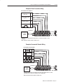
Example of Pulse Transmitter Wiring
incremental encoder Channel 0
#!&$ ')
',&+) !+
G
+
#!&$ ') ',&+) $#)0
+#'&()*+
Z
+
B
+
#!&$ ')
,('-& ',&+#&!
A
+
#!&$ &(,+*
.+)&$ '-)
,(($/
.%($ ' (,$* +)&*%#++) -#+" (,$* +)#& ') '&&+#'& ' "&&$ ) ) +'
-#)#&! +$
Note: '++ $#&* #&#+ *#!&$* &'+ $-/* ,*
Example of Incremental Encoder Wiring
incremental encoder Channel 0
G
+
Z
+
B
+
A
+
#!&$ &(,+*
.+)&$ '-)
,(($/
.%($ ' #&)%&+$ &') -#+" (,$* +)#&* -#+" ') -#+"',+ ) )& &')
!+ ,&+#'& ') '&&+#'& ' "&&$ ) ) +' -#)#&! +$
Note: '++ $#&* #&#+ *#!&$* &'+ $-/* ,*
,$#+#'& 0 / 2–14
How to Install Your Incremental Encoder Module
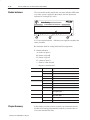
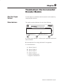
Module Indicators
The incremental encoder module has one status indicator (PWR) that
is on when power is applied to the module, and one input status
indicator for each input (12 in all).
1794-ID2
2 CH INCREMENTAL ENCODER MODULE
A
B
Z
G
+
-
C
A
B
Z
1
G
B
+
-
A
A = Power/status indicator – indicates power applied to module and
status of module.
B = Insertable label for writing individual I/O assignments.
C = Status Indicators –
A = Status of input A
B = Status of input B
Z = Status of input Z
G = Status of input G
+ = Positive count detected
– = Negative count detected
Indicator
Indication
Explanation
A
Yellow
Input A active
Off
Input A not active
Yellow
Input B active
Off
Input B not active
Yellow
Input Z active
Off
Input Z not active
Yellow
Input G active
Off
Input G not active
+
Yellow
On when a positive pulse is detected; turns off
on negative pulse.
-
Yellow
On when a negative pulse is detected; turns off
on positive pulse.
OK
Red
Red during initialization after power turned on
Green
Green when initialization is completed
B
Z
G
Chapter Summary
In this chapter, we told you how to install your incrementa encoder
module in an existing programmable controller system and how to
wire to the terminal base units.
Programming Your
Incremental Encoder Module
What This Chapter
Contains
To initiate communication between the incremental encoder module
and your PLC processor, you must enter block transfer instructions
into your ladder logic program. Use this chapter to enter the
necessary block transfer instructions into your ladder logic program.
To edit your ladder logic you
!%# " #!$# !$%#&%"!$ ( ' #"$$"#$ ( ' #"$$"#$ ( #"$$"#$ Enter Block Transfer
Instructions
See page
The incremental encoder module communicates with the PLC
processor through bidirectional block transfers. This is the
sequential operation of both read and write block transfer
instructions.
Before you configure the module, you need to enter block transfer
instructions into your ladder logic. The following example programs
illustrate the minimum programming required for communication to
take place between the module and a PLC processor. These
programs can be modified to suit your application requirements.
A configuration block transfer write (BTW) is initiated when the
module is first powered up, and subsequently only when the
programmer wants to enable or disable features of the module. The
configuration BTW sets the bits which enable the programmable
features of the module, such as scalars and alarm values, etc. Block
transfer reads are performed to retrieve information from the module.
Block transfer read (BTR) programming moves status and data from
the module to the processor’s data table. The processor user program
initiates the request to transfer data from the module to the processor.
The transferred words contain module status, channel status and
input data from the module.
Your program should monitor status bits, block transfer read and
block transfer write activity.
&%"! ( ' 3–2
Programming Your Incremental Encoder Module
PLCĆ2 Family Processor
The 1794 incremental encoder module is not recommended for use
with PLC-2 family programmable controllers due to the number of
digits needed for high resolution.
Important:
The incremental encoder module functions with
reduced performance in PLC-2 systems. Because the
module does not support BCD and the PLC-2 processor
is limited to values of 4095 (12 bit binary), many values
returned in the BTR file may not provide meaningful
data to the PLC-2 processor.
PLCĆ5 Family Processor
Block transfer instructions with the PLC-5 processor use a control
file and a data file. The block transfer control file contains the data
table section for module location, the address of the block transfer
data file and other related data. The block transfer data file stores
data that you want transferred to the module (when programming a
BTW) or from the module (when programming a BTR).
The programming terminal prompts you to create a control file when
a block transfer instruction is being programmed. A different block
transfer control file is used for the read and write instructions
for your module.
Programming Your Incremental Encoder Module
8
1/$&22/1
1/(1"- 6"-0,&
3–3
4.( )& -/%4,& *2 ,/$"3&% *. 1"$+ (1/40 2,/3 )& *.3&(&1 $/.31/, '*,& 23"132 "3 )& %"3" 2&.3 #7 3)&
8
01/$&22/1 3/ 3)& -/%4,& 23"132 "3 ".% *2 5/1%2 ,/.( 3 0/5&1 40 *. -/%& /1 5)&. 3)&
01/$&22/1 *2 '*123 25*3$)&% '1/- 3/ 3)& 42&1 01/(1"- &."#,&2 " #,/$+ 31".2'&1 51*3& 3/ $/.'*(41& 3)& -/%4,&
*123 2$". /'
,"%%&1 /1 !
/.31/, *,&
!
!
/%4,& 70&
"$+
1/40
,/3
/.31/,
"3"*,&
&.(3)
/.3*.4/42
&.&1*$ 4.( )& -/%4,& *2 ,/$"3&% *. 1"$+ (1/40 2,/3 )& *.3&(&1 $/.31/, '*,& 23"132 "3 )& %"3" /#3"*.&% #7 3)&
8
01/$&22/1 '1/- 3)& -/%4,& *2 0,"$&% *. -&-/17 23"13*.( "3 ".% *2 5/1%2 ,/.( ,)& 01/(1"$/.3*.4/42,7 0&1'/1-2 1&"% #,/$+ 31".2'&12 3/ 1&"% %"3" '1/- 3)& -/%4,&
."#,& *3
SLCĆ5 Programming
/.31/, *,&
/%4,& 70&
"$+
1/40
,/3
/.31/,
"3"*,&
&.(3)
/.3*.4/42
&.&1*$ The SLC-5 programs (using the 1747-SN scanner) follow the same
logic as the PLC-5 family programs in the previous example.
Differences occur in the implementation of block transfers due to the
use of “M” files in the SLC system.
Configuration data for the FLEX I/O incremental encoder module
and the 1747-SN scanner must be in place before executing the
following programs. Chapter 4 contains information on module
configuration.
For more information on using the 1747-SN scanner module and
block transfer programming, refer to publication 1747-6.6, “Remote
I/O Scanner User Manual.”
4#,*$"3*/. 8 "7 3–4
Programming Your Incremental Encoder Module
Figure 3.1SLC Programming for the 1794ĆOF4I Isolated
Analog Output Module
Program Action
0000
39*5"4.7
!-.6 582, (32+.,85*6 7-* '03(/ 75&26+*5 34*5&7.32
7;4* 0*2,7- &2) &))5*66 &7 439*5<84 .7
1867 '* 6*7 73 73 .2).(&7* & ! &2)
'.7 1867 '* 73 .2).(&7* & !#
0001
! 67&786 .6 (34.*) 73 7-* &5*& 9-*2 & !
.6 .2 453,5*66
!
!%!
$
"
!
!
!#%!
$
"
!
!
$
"
!
!
! !!"
! !!"
!!
0002
"20&7(- 7-* '.7 7-&7 (327.28*6 73 (-*(/ 7-* ! 67&786
"
!!
0003
!# 67&786 .6 (34.*) 73 7-* &5*& 9-*2 &
!# .6 .2 453,5*66
!#
$
"
!
!
!# !!"
0004
"20&7(- 7-* '.7 7-&7 (327.28*6 73 (-*(/ 7-* !# 67&786
!#!
!#!
!3 2*:7 4&,*
8'0.(&7.32 <" &; !# !!"
"
Programming Your Incremental Encoder Module
3–5
Program Action
0005
#!#
&/,3 ( #! 79**,77-911< *4251,8,7 (3+ 8/,
+43, )08 07 +,8,*8,+ 8/, #! +(8( 07 *450,+
0384 8/, 84 (6,(
'
"$!
"#
#
#! $
#!#
$
#!"##$"
&/, ( #! ,6646 4**967 8/, ,6646 *4+, 07
24:,+ 84 0006
#!!!!#
%
%
"$!
"#
#! $
#!#
$
#!"##$"
&/,3 ( #& 79**,77-911< *4251,8,7 (3+ 8/,
+43, )08 07 +,8,*8,+ 8/, #! +(8( 07 *450,+
0384 8/, 84 (6,(
0007
#&#
#4 3,;8 5(.,
#& $
#&#
$
#&"##$"
9)10*(8043 =$ (< 3–6
Programming Your Incremental Encoder Module
Program Action
When a BTW occurs, the error code is moved
to N7:17.
0008
BTW ERROR BIT
B3:10
MOV
MOVE
SOURCE
12
#M1:1.203
6
#N7:17
0<
DEST
BTW PENDING
B3:15
U
0
BTW ENABLE BIT
B3:110
U
15
CHECK BTW STATUS
B3:15
L
1
0009
BTR ENABLE BIT
B3:100
BTR DONE BIT
B3:0
15
This rung executes BTRs continuously, as fast
as possible.
BTR ERROR BIT
B3:0
13
12
BTR PENDING
B3:5
L
0
BTR ENABLE BIT
B3:100
L
15
0010
One BTW is triggered at power up. Four words of
data starting at N7:10 is sent to the 1794ĆID2
module.
TRIGGER
FOR
BTW
B7:20
0
BTW
ENABLE
BIT
B3:110
15
BTW
DONE
BIT
B3:10
13
BTW
ERROR
BIT
B3:10
12
COP
COPY FILE
SOURCE
DEST
LENGTH
#N7:10
#M1:1.210
7
BTW ENABLE BIT
B3:110
L
15
BTW PENDING
B3:15
L
0
To next page.
Publication 1794ĆUM015B-EN-P - May 2001
Programming Your Incremental Encoder Module
3–7
Program Action
0011
()0 #-,1/-* 4-/$ )0 +-3%$ 1- 1(% &)*%
&-/ 1(% 0#!,,%/ +-$2*% 4()*% 1(% )0 ),
./-'/%00 2,1)* 1(% %,!"*% $-,% !,$ %//-/ ")10
!/% 12/,%$ -&&
0012
()0 #-,1/-* 4-/$ )0 +-3%$ 1- 1(% &)*%
&-/ 1(% 0#!,,%/ +-$2*% 4()*% 1(% )0 ),
./-'/%00 2,1)* 1(% %,!"*% $-,% !,$ %//-/ ")10
!/% 12/,%$ -&&
0013
2"*)#!1)-, 6
!5 3–8
Programming Your Incremental Encoder Module
Chapter Summary
In this chapter, you learned how to program your ID2 incremental
encoder module using block transfer instructions and ladder logic.
Now, you can configure your module.
! !
! #
" Writing Configuration to and
Reading Status from Your
Module with a Remote I/O
Adapter
What This Chapter
Contains
Configuring Your
Incremental Encoder
Module
In this chapter, we tell you about:
For information on
See page
*)"%#/,%)# */, * /'! ! %)# . ",*( */, * /'! ++%)# . "*, .$! * /'! ),!(!).' )* !, * /'! 1 (#! '! ++%)#
'*& ,)-"!, ! *, --%#)(!).- %.*, !"%)%.%*)- "*, '*& ,)-"!, ! *, - '*& ,)-"!, ,%.! *, --%#)(!).- %.*, !"%)%.%*)- "*, .$! '*& ,)-"!, ,%.! *, - The incremental encoder module is configured using a group of data
table words that are transferred to the module using a block transfer
write instruction.
Some of the software configurable features available are:
•
•
•
•
•
number of inputs
encoder multiplier
gate function
latch function
rollover
Configure your module for its intended operation by means of your
programming terminal and write block transfers.
Note: Programmable controllers that use 6200 software (release 4.2
or higher) programming tools can take advantage of the IOCONFIG
Addendum utility to configure this module. IOCONFIG Addendum
uses menu–based screens for configuration without having to set
individual bits in particular locations. Refer to your 6200 software
literature for details.
Important:
It is strongly recommended that you use IOCONFIG
Addendum to configure this module. The IOCONFIG
Addendum utility greatly simplifies configuration. If
the IOCONFIG Addendum is not available, you must
enter data directly into the data table. Use this chapter
as a reference when performing this task.
/'%.%*) 1 0 4–2
Writing Configuration to and Reading Status from Your Module with a Remote I/O Adapter
During normal operation, the processor transfers from 1 to 4 words
to the module when you program a BTW instruction to the module’s
address.
Reading Data From Your
Module
Mapping Data for the
Module
Read programming moves status and data from the frequency input
module to the processor’s data table in one I/O scan. The processor’s
user program initiates the request to transfer data from the
incremental encoder module to the processor.
The following read and write words and bit/word descriptions
describe the information written to and read from the incremental
encoder module. The module uses up to 8 words of input data and up
to 5 words of output data. Each word is composed of 16 bits.
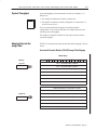
Incremental Encoder Module (1794ĆID2) Image Table Mapping
Module Image
I/O Image
R
PR1 PR0 S1
S0
C1
C0
G1
Z1
B1
A1
G0
Z0
Input Size
Store 0 - Stored Counter Value on channel 0
Store 1 - Stored Counter Value on channel 1
B0
A0
Channel 0 - current counter value
Channel 1 - current counter value
Channel 0 - Counter word readback
Channel 1 - Counter word readback
Code for identification of software version
Channel 0 Control Word - Sets the function of counter 0
Channel 1 Control Word - Sets the function of counter 1
Output Size
Channel 0 Preset - value to load or compare with counter 0
Preset 1 - value to load or compare with counter 1
Control Word 2 - Sets filter function for both counters
Writing Configuration to and Reading Status from Your Module with a Remote I/O Adapter
4–3
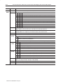
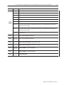
Block Transfer Read Word Assignments for the Incremental
Encoder Module (1794-ID2)
(Octal Bit⇒)
17
16
15
14
13
12
11
10
07
06
05
04
03
02
01
00
Dec. Bit ⇒
15
14
13
12
11
10
09
08
07
06
05
04
03
02
01
00
"
"
Word⇓
Read
*#//'- 402'& %05/4'2 6#-5' 0/ %*#//'- *#//'- 402'& %05/4'2 6#-5' 0/ %*#//'- *#//'- %522'/4 %05/4'2 6#-5' 0/ %*#//'- *#//'- %522'/4 %05/4'2 6#-5' 0/ %*#//'- *#//'- 05/4'2 702& 2'#&$#%,
*#//'- 05/4'2 702& 2'#&$#%,
'6+3+0/ 2'#& 30(47#2' 6'23+0/ %0&'
!*'2' 4#453 0( +/154 %*#//'- $+4 7*'/ +/154 +3 0/
4#453 0( +/154 %*#//'- $+4 7*'/ +/154 +3 0/
" 4#453 0( +/154 " %*#//'- $+4 7*'/ +/154 +3 0/
4#453 0( +/154 %*#//'- $+4 7*'/ +/154 +3 0/
4#453 0( +/154 %*#//'- $+4 7*'/ +/154 +3 0/
4#453 0( +/154 %*#//'- $+4 7*'/ +/154 +3 0/
4#453 0( +/154 %*#//'- $+4 7*'/ +/154 +3 0/
" 4#453 0( +/154 " %*#//'- $+4 7*'/ +/154 +3 0/
#- 7*'/ $+4 +3 3'4 %05/4'2 *#3 $''/ %#-+$2#4'& 2'3'4 $8 #-'3'4
#- 7*'/ $+4 +3 3'4 %05/4'2 *#3 $''/ %#-+$2#4'& 2'3'4 $8 #-'3'4
402'& 7*'/ $+4 +3 3'4 %05/4'2 6#-5' *#3 $''/ 3#6'& +/ 402' 2'3'4 $8 402''3'4
402'& 7*'/ $+4 +3 3'4 %05/4'2 6#-5' *#3 $''/ 3#6'& +/ 402' 2'3'4 $8 402''3'4
/%' # 402' 0%%523 #/& #2' 0/ 5/4+- %-'#2'& $8 402''3'4 %05/4'2 702& $+4 2'3'4 2'#%*'& 7*'/ $+4 +3 3'4 %05/4'2 *#3 2'#%*'& 6#-5' 0( 12'3'4
2'3'4 $8 2'3'4'3'4
2'3'4 2'#%*'& 7*'/ $+4 +3 3'4 %05/4'2 *#3 2'#%*'& 6#-5' 0( 12'3'4
2'3'4 $8 2'3'4'3'4
Bit/Word Definitions for Block Transfer Read Words for the
Incremental Encoder Module
Read
Word
!02& Bit
Definition
+4 Status for input A 15-3' 42#/3.+44'2 *+3 $+4 7*'/ 3'4 +/&+%#4'3 # 3+)/#- #4 +4 Status for input B 15-3' 42#/3.+44'2 *+3 $+4 7*'/ 3'4 +/&+%#4'3 # 3+)/#- #4 +4 Status for input Z 15-3' 42#/3.+44'2 *+3 $+4 7*'/ 3'4 +/&+%#4'3 # 3+)/#- #4 "
+4 Status for input G 15-3' 42#/3.+44'2 *+3 $+4 7*'/ 3'4 +/&+%#4'3 # 3+)/#- #4 +4 Status for input A 15-3' 42#/3.+44'2 *+3 $+4 7*'/ 3'4 +/&+%#4'3 # 3+)/#- #4 +4 Status for input B 15-3' 42#/3.+44'2 *+3 $+4 7*'/ 3'4 +/&+%#4'3 # 3+)/#- #4 5$-+%#4+0/ 9 #8 4–4
Read
Word
Writing Configuration to and Reading Status from Your Module with a Remote I/O Adapter
Bit
Definition
+5 Status for input Z 16-4' 53#/4.+55'3 *+4 $+5 8*'/ 4'5 +/&+%#5'4 # 4+)/#- #5 "
+5 Status for input G 16-4' 53#/4.+55'3 *+4 $+5 8*'/ 4'5 +/&+%#5'4 # 4+)/#- #5 +5 Cal 0 *+4 $+5 8*'/ 4'5 +/&+%#5'4 5*#5 %06/5'3 *#4 $''/ %#-+$3#5'& *+4 $+5 +4 3'4'5 $9 #-'4'5
+5 Cal 1 *+4 $+5 8*'/ 4'5 +/&+%#5'4 5*#5 %06/5'3 *#4 $''/ %#-+$3#5'& *+4 $+5 +4 3'4'5 $9 #-'4'5
+5 Store 0 *+4 $+5 8*'/ 4'5 +/&+%#5'4 # %06/5'3 7#-6' +4 4#7'& +/ 4503' *+4 $+5 +4 3'4'5 $9 503''4'5
+5 Store 1 *+4 $+5 8*'/ 4'5 +/&+%#5'4 # %06/5'3 7#-6' +4 4#7'& +/ 4503' *+4 $+5 +4 3'4'5 $9 503''4'5
+5 Preset Reached 0 (PR0) !*'/ 5*+4 $+5 +4 4'5 +/ #-- %0/(+)63#5+0/ .0&'4 5*' %06/5'3 7#-6' '26#-4 5*'
13'4'5 7#-6' '+5*'3 +/ # 104+5+7' 03 /')#5+7' &+3'%5+0/ *+4 $+5 +4 3'4'5 $9 3'4'5'4'5 #/& %#/ 0/-9 $' 4'5
#)#+/ #(5'3 #5 -'#45 .03' 16-4'
+5 Preset Reached 1 (PR1) !*'/ 5*+4 $+5 +4 4'5 +/ #-- %0/(+)63#5+0/ .0&'4 5*' %06/5'3 7#-6' '26#-4 5*'
13'4'5 7#-6' '+5*'3 +/ # 104+5+7' 03 /')#5+7' &+3'%5+0/ *+4 $+5 +4 3'4'5 $9 3'4'5'4'5 #/& %#/ 0/-9 $' 4'5
#)#+/ #(5'3 #5 -'#45 .03' 16-4'
+5 06/5 &+3'%5+0/ /%3'#4'&'%3'#4' %06/5'3 7#-6' 0( %06/5'3 4'5 50 #5 45#3561
-#45 16-4' &'%3'#4'& %06/5'3 7#-6'
-#45 16-4' +/%3'#4'& %06/5'3 7#-6'
+5 06/5 &+3'%5+0/ /%3'#4'&'%3'#4' %06/5'3 7#-6' 0( %06/5'3 4'5 50 #5 45#3561
-#45 16-4' &'%3'#4'& %06/5'3 7#-6'
-#45 16-4' +/%3'#4'& %06/5'3 7#-6'
!03& +54 Store 0 #7'& %06/5'3 7#-6' 0/ %*#//'- !03& +54 Store 1 #7'& %06/5'3 7#-6' 0/ %*#//'- !03& +54 Channel 0 Current Counter Value 633'/5 7#-6' +/ %06/5'3 !03& +54 Channel 1 Current Counter Value 633'/5 7#-6' +/ %06/5'3 !03& +54 Channel 0 Readback 06/5'3 803& 3'#&$#%, -#45 7#-6' 83+55'/ 50 83+5' 803& !03& +54 Channel 0 Readback 06/5'3 803& 3'#&$#%, -#45 7#-6' 83+55'/ 50 83+5' 803& !03& +54 Revision Read +&'/5+(+%#5+0/ 0( -#5'45 40(58#3' 7'34+0/ %0&'
!03& %0/5+/6'&
6$-+%#5+0/ : #9 Writing Configuration to and Reading Status from Your Module with a Remote I/O Adapter
4–5
Block Transfer Write Word Assignments for the Incremental
Encoder Module
(Octal Bit) ⇒
17
16
15
14
13
12
11
10
07
06
05
04
03
02
01
00
Dec. Bit ⇒
15
14
13
12
11
10
09
08
07
06
05
04
03
02
01
00
Word⇓
Write
.'33+1 438641 $46* !+87 8.+ ,93)8/43 4, )4938+6 .'33+1 438641 $46* !+87 8.+ ,93)8/43 4, )4938+6 .'33+1 6+7+8 :'19+ 84 14'* 46 )425'6+ ;/8. )4938+6 .'33+1 6+7+8 :'19+ 84 14'* 46 )425'6+ ;/8. )4938+6 438641 $46* !+87 8.+ ,/18+6 ,93)8/43 ,46 (48. )4938+67
Bit/Word Definitions for the Block Transfer Write Words for the
Incremental Encoder Module
Write
Word
Bit
$6/8+
$46* Channel 0 Control Word - 438641 ;46* ,46 7+88/3- 8.+ ,93)8/43 4, )4938+6 /87 4*+ !+1+)8/43 (/87
4938/3- 43 547/8/:+ 6/7/3- +*-+ 4, /3598 7/-3'1 #5*;3 )4938/3- *+8+62/3+* (< 9'*6'896+ +3)4*+6 %
9'*6'896+ +3)4*+6 %
9'*6'896+ +3)4*+6 %
4938/3- 95 43 8.+ 547/8/:+ +*-+ 4, /3598 7/-3'1 '3* *4;3 43 547/8/:+ +*-+ 4, /3598 7/-3'1 4 )4938 ,93)8/43
4 )4938 ,93)8/43
4 )4938 ,93)8/43
Definition
/8 Preset (Reset) bit - 547/8/:+ +*-+ 43 8./7 (/8 24:+7 8.+ :'19+ /3 6+7+8 % 84 4938+6 % /3*+5+3*+38 4, 6+7+8
3'(1+ " "4 97+ 6+7+8 '7 +7+8 97+ ' )4938 :'19+ 4, /3 8.+ 6+7+8 :'19+ ;46*
/8 Enable Z Preset bit - $.+3 8./7 (/8 /7 7+8 ' 547/8/:+ +*-+ 43 & 56+14'*7 4938+6 % 6+7+8 % /3*+5+3*+38 4,
'1 3'(1+ " , & /7 )43,/-96+* 84 *4 !846+ '3* 6+7+8 +7+8 8.+ !846+ ;/11 4))96 ,/678
/8 Count Enable bit - $.+3 8./7 /7 7+8 8.+ /3)6+2+38'1 +3)4*+6 /7 +3'(1+*
/87 /87 Calibration Control bits - (/87 '3* Enable bit - $.+3 8./7 (/8 /7 7+8 8.+ )4938+6 )'3 (+ )'1/(6'8+*
Direction bit - $.+3 8./7 (/8 7+8 )'1/(6'8/43 /7 5+6,462+* /3 ' 3+-'8/:+ */6+)8/43 ;.+3 6+7+8 )'1/(6'8/43
/7 5+6,462+* /3 ' 547/8/:+ */6+)8/43
Reset bit - '1/(6'8/43 /7 ')034;1+*-+* '3* ' 3+; )'1/(6'8/43 /7 +3'(1+* 43 ' 547/8/:+ +*-+ 43 8./7 (/8
Gate Control bits
4 -'8+ ,93)8/43 43 /3598 4938/3- 431< /, /7 ./-. ')8/:+
4938/3- 431< /, /7 14; /3')8/:+
".+ )4938+6 )'3 (+ )'1/(6'8+* ;.+3 /7 ./-. ')8/:+
9(1/)'8/43 =# '< 4–6
Writing Configuration to and Reading Status from Your Module with a Remote I/O Adapter
Write
Word
Bit
"3-5)
"13( '105-06)(
-54 "3-5)
"13( Definition
Store Control bits - ,)4) &-54 8-.. 53-++)3 % 513) 10.: -* 5,) ',%00). 513) 45%564 &-5 13 -4
'.)%3)( %7) 5,) '1605)3 7%.6) 10 5,) 214-5-7) )(+) 1* $ -* 513)( # %7) 5,) '1605)3 7%.6) 10 5,) 214-5-7) )(+) 1* -* 513)( # %7) 5,) '1605)3 7%.6) 10 5,) 0)+%5-7) )(+) 1* -* 513)( # %7) 5,) '1605)3 7%.6) 10 5,) 214-5-7) )(+) %0( 0)+%5-7) )(+) 1* -* 513)( # -5 Rollover bit - ",)0 4)5 5,) '1605)3 '16054 62 51 5,) 23)4)5 %0( 5,)0 3)45%354 %5 * 5,-4 &-5 -4 3)4)5 015
31..17)3 5,) 31..17)3 23)4)5 7%.6) ,)9 ()'-/%.
-5 Store Reset bit - 214-5-7) )(+) 10 5,-4 &-5 3)4)54 513) # -0 -+0%.4
-5 Preset Reset bit - 214-5-7) )(+) 10 5,-4 &-5 3)4)54 3)4)5 )%',)( -0 -+0%.4
Channel 1 Control Word - 10531. 813( *13 4)55-0+ 5,) *60'5-10 1* '1605)3 -54 Mode Selection bits
1605-0+ 10 214-5-7) 3-4-0+ )(+) 1* -0265 4-+0%. !2(80 '1605-0+ ()5)3/-0)( &: 6%(3%563) )0'1()3 #
6%(3%563) )0'1()3 #
6%(3%563) )0'1()3 #
1605-0+ 62 10 5,) 214-5-7) )(+) 1* -0265 4-+0%. %0( (180 10 214-5-7) )(+) 1* -0265 4-+0%. 1 '1605 *60'5-10
1 '1605 *60'5-10
1 '1605 *60'5-10
-5 Preset bit - 214-5-7) )(+) 10 5,-4 &-5 /17)4 5,) 7%.6) -0 3)4)5 # 51 1605)3 # -0()2)0()05 1* 3)4)5 0%&.)
-5 Preset Enable bit - ",)0 5,-4 &-5 -4 4)5 % 214-5-7) )(+) 10 $ 23).1%(4 1605)3 # 3)4)5 # -0()2)0()05 1* %.
0%&.)
-5 Count Enable bit - ",)0 5,-4 -4 4)5 5,) -0'3)/)05%. )0'1()3 -4 '1605-0+
6&.-'%5-10 ;! %: Writing Configuration to and Reading Status from Your Module with a Remote I/O Adapter
Write
Word
Bit
%57+ *54904:,+
098 4–7
Definition
Calibration Control bits - )098 (4+ Enable bit - %/,4 9/08 )09 08 8,9 9/, *5:49,7 *(4 ), *(20)7(9,+
Direction bit - %/,4 9/08 )09 8,9 *(20)7(9054 08 6,7-573,+ 04 ( 4,.(90;, +07,*9054 </,4 7,8,9 *(20)7(9054
08 6,7-573,+ 04 ( 658090;, +07,*9054
Reset bit - (20)7(9054 08 (*145<2,+.,+ (4+ ( 4,< *(20)7(9054 08 ,4()2,+ 54 ( 658090;, ,+., 54 9/08 )09
098 098 Gate Control bits
5 .(9, -:4*9054 54 046:9 5:4904. 542> 0- 08 /0./ (*90;,
5:4904. 542> 0- 08 25< 04(*90;,
(20)7(9054 0- 08 /0./ (*90;, (4+ Store Control bits - "/,8, )098 <022 970..,7 ( !957, 542> 0- 9/, */(44,2 !957, 89(9:8 )09 57 08
*2,(7,+ !(;, 9/, *5:49,7 ;(2:, 54 9/, 658090;, ,+., 5- ' 0- !957, & !(;, 9/, *5:49,7 ;(2:, 54 9/, 658090;, ,+., 5- 0- !957, & !(;, 9/, *5:49,7 ;(2:, 54 9/, 4,.(90;, ,+., 5- 0- !957, & !(;, 9/, *5:49,7 ;(2:, 54 9/, 658090;, ,+., (4+ 4,.(90;, ,+., 5- 0- !957, & 09 Rollover bit - %/,4 8,9 9/, *5:49,7 *5:498 :6 95 9/, 67,8,9 (4+ 9/,4 7,89(798 (9 - 9/08 )09 08 7,8,9 459
75225;,7 9/, 75225;,7 67,8,9 ;(2:, /,= +,*03(2
09 Store Reset bit - 658090;, ,+., 54 9/08 )09 7,8,98 !957, & 04 !0.4(28
09 Store Reset bit - 658090;, ,+., 54 9/08 )09 7,8,98 7,8,9 ,(*/,+ 04 !0.4(28
%57+ 098 Preset 0 $(2:, 95 25(+ 57 *536(7, <09/ *5:49,7 %57+ 098 Preset 1 $(2:, 95 25(+ 57 *536(7, <09/ *5:49,7 %57+ 09 Filter A0 enable - %/,4 9/08 )09 08 8,9 (4+( *5:49,7 08 04 35+, 6:28, *5:4904. 80.4(2 08 -029,7,+ )> (
+0.09(2 25< 6(88 -029,7 <09/ 8,2,*9()2, -029,7 *5489(49
09 Filter A1 enable - %/,4 9/08 )09 08 8,9 (4+( *5:49,7 08 04 35+, 6:28, *5:4904. 80.4(2 08 -029,7,+ )> (
+0.09(2 25< 6(88 -029,7 <09/ 8,2,*9()2, -029,7 *5489(49
09 @
#4:8,+
098 @
@
1' 57 30403:3 38 6:28,<0+9/
1? 57 30403:3 38 6:28,<0+9/
1? 57 30403:3 38 6:28,<0+9/
1? 57 30403:3 38 6:28,<0+9/
098 @
@
Chapter Summary
Filter Constant bits - "/08 *5489(49 08 *53354 95 )59/ *5:49,78
,8,7;,+ 8,9 95 In this chapter, you learned how to configure your module’s features
and enter your data.
:)20*(9054 @# (> 4–8
Writing Configuration to and Reading Status from Your Module with a Remote I/O Adapter
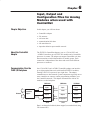
How Communication Takes
Place and I/O Image Table
Mapping with the DeviceNet
Adapter
What This Chapter
Contains
In this chapter, we tell you about:
About DeviceNetManager
Software
For information on
See page
*/. !0%!!.)#!, *".1,! *''! .,/./,! +.!, )+/. ../- *, 2-.!( $,*/#$+/. ++%)# . %).* .$! (#! '! ),!(!).' )* !, * /'! 3 (#! '! ++%)# '*& ,)-"!, ! *, --%#)(!).- '*& ,)-"!, ,%.! *, --%#)(!).- *, %. !-,%+.%*)- !"/'.- DeviceNetManager software is a tool used to configure your FLEX
I/O DeviceNet adapter and its related modules. This software tool
can be connected to the adapter via the DeviceNet network.
You must understand how DeviceNetManager software works in
order to add a device to the network. Refer to the DeviceNetManager
Software User Manual, publication 1787-6.5.3.
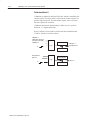
Polled I/O Structure
Output data is received by the adapter in the order of the installed
I/O modules. The Output data for Slot 0 is received first, followed
by the Output data for Slot 1, and so on up to slot 7.
The first word of input data sent by the adapter is the Adapter Status
Word. This is followed by the input data from each slot, in the order
of the installed I/O modules. The Input data from Slot 0 is first after
the status word, followed by Input data from Slot 2, and so on up to
slot 7.
DeviceNet Adapter
Read Data
Network READ
+.!, ../'*. )+/. .
'*. )+/. .
'*. )+/. .
Write Data
,%.!
I/O Module I/O Module
Slot 0
Slot 1
I/O Module
Slot 7
'*. /.+/. .
'*. /.+/. .
Network WRITE
!
'*. /.+/. .
/'%.%*) 3 2 5–2
How Communication Takes Place and I/O Image Table Mapping with the DeviceNet Adapter
Adapter Input Status Word
The input status word consists of:
• I/O module fault bits – 1 status bit for each slot
• node address changed – 1 bit
• I/O status – 1 bit
*#/($ /(. '.(*.
(*.
(*.
*. -$#
(*.
(*.
(*.
.&,*/%& (*.
(*.
'.
. .$ '.
*#$ ##,$-- & )%$# '.
The adapter input status word bit descriptions are shown in the
following table.
Bit Description
Bit
Explanation
&'- !'. '- -$. 0&$) ) $,,*, '- #$.$".$# ') -(*. +*-'.'*) &'- !'. '- -$. 0&$) ) $,,*, '- #$.$".$# ') -(*. +*-'.'*) &'- !'. '- -$. 0&$) ) $,,*, '- #$.$".$# ') -(*. +*-'.'*) &'- !'. '- -$. 0&$) ) $,,*, '- #$.$".$# ') -(*. +*-'.'*) &'- !'. '- -$. 0&$) ) $,,*, '- #$.$".$# ') -(*. +*-'.'*) &'- !'. '- -$. 0&$) ) $,,*, '- #$.$".$# ') -(*. +*-'.'*) &'- !'. '- -$. 0&$) ) $,,*, '- #$.$".$# ') -(*. +*-'.'*) &'- !'. '- -$. 0&$) ) $,,*, '- #$.$".$# ') -(*. +*-'.'*) *#$ ##,$-- & )%$#
&'- !'. '- -$. 0&$) .&$ )*#$ ##,$-- -0'."& -$..')% & - !$$)
"& )%$# -')"$ +*0$, /+
. .$
'. '#($
'. ,/)
*#/($ /(.
.&,/ *. /-$# -$). - 2$,*$-
Possible causes for an I/O Module Fault are:
•
•
•
•
•
transmission errors on the Flex I/O backplane
a failed module
a module removed from its terminal base
incorrect module inserted in a slot position
the slot is empty
The node address changed bit is set when the node address switch
setting has been changed since power up. The new node address does
not take affect until the adapter has been powered down and then
powered back up.
/!('" .'*) 3 1 How Communication Takes Place and I/O Image Table Mapping with the DeviceNet Adapter
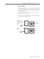
System Throughput
5–3
System throughput, from incremental encoder to backplane, is a
function of:
• the configured minimum frequency sample time
• the number of channels actually configured for connection to a
specific sensor (0 or 1)
You can set the minimum frequency time during module
configuration. The selection influences the sample data rate, thus
affecting system throughput.
The number of channels included in each input scan also affects
system throughput.
Mapping Data into the
Image Table
FLEX I/O incremental encoder module data table mapping is shown
below.
Incremental Encoder Module (1794ĆID2) Image Table Mapping
Module Image
I/O Image
R
PD1 PD0 S1
S0
C1
C0
G1
Z1
B1
A1
G0
Z0
Input Size
Store 0 - Saved Counter Value on channel 0
Store 1 - Saved Counter Value on channel 1
B0
A0
Channel 0 - current counter value on channel 0
Channel 1 - current counter value on channel 1
Channel 0 - Counter word readback
Channel 1 - Counter word readback
Code for identification of software version
Channel 0 Control Word- sets the function of counter 0
Channel 1 Control Word - sets the function of counter 1
Output Size
Channel 0 Preset - value to load or compare with counter 0
Channel 1 Preset - value to load or compare with counter 1
Control Word 2 - Sets filter function for both channels
Not used
Not used
5–4
How Communication Takes Place and I/O Image Table Mapping with the DeviceNet Adapter
Block Transfer Read Word Assignments for the Incremental
Encoder Module (1794-ID2)
(Octal Bit⇒)
17
16
15
14
13
12
11
10
07
06
05
04
03
02
01
00
Dec. Bit ⇒
15
14
13
12
11
10
09
08
07
06
05
04
03
02
01
00
Word⇓
Read
.2 31%$
(!--%+ 2.0%$ #.3-2%0 4!+3% .- #(!--%+ (!--%+ 2.0%$ #.3-2%0 4!+3% .- #(!--%+ (!--%+ #300%-2 #.3-2%0 4!+3% .- #(!--%+ (!--%+ #300%-2 #.3-2%0 4!+3% .- #(!--%+ (!--%+ .3-2%0 5.0$ 0%!$"!#*
(!--%+ .3-2%0 5.0$ 0%!$"!#*
%4)1).- 0%!$ 1.&25!0% 4%01).- #.$%
(%0% 2!231 .& )-/32 #(!--%+ ")2 5(%- )-/32 )1 . 2!231 .& )-/32 #(!--%+ ")2 5(%- )-/32 )1 . 2!231 .& )-/32 #(!--%+ ")2 5(%- )-/32 )1 . 2!231 .& )-/32 #(!--%+ ")2 5(%- )-/32 )1 . 2!231 .& )-/32 #(!--%+ ")2 5(%- )-/32 )1 . 2!231 .& )-/32 #(!--%+ ")2 5(%- )-/32 )1 . 2!231 .& )-/32 #(!--%+ ")2 5(%- )-/32 )1 . 2!231 .& )-/32 #(!--%+ ")2 5(%- )-/32 )1 . !+ 5(%- ")2 )1 1%2 #.3-2%0 (!1 "%%- #!+)"0!2%$ 0%1%2 "6 !+%1%2
!+ 5(%- ")2 )1 1%2 #.3-2%0 (!1 "%%- #!+)"0!2%$ 0%1%2 "6 !+%1%2
2.0%$ 5(%- ")2 )1 1%2 #.3-2%0 4!+3% (!1 "%%- 1!4%$ )- 2.0% 0%1%2 "6 2.0%%1%2
2.0%$ 5(%- ")2 )1 1%2 #.3-2%0 4!+3% (!1 "%%- 1!4%$ )- 2.0% 0%1%2 "6 2.0%%1%2
-#% ! 2.0% .##301 !-$ !0% .- 3-2)+ #+%!0%$ "6 2.0%%1%2 #.3-2%0 5.0$ ")2 0%1%2 0%!#(%$ 5(%- ")2 )1 1%2 #.3-2%0 (!1 0%!#(%$ 4!+3% .& /0%1%2
0%1%2 "6 0%1%2%1%2
0%1%2 0%!#(%$ 5(%- ")2 )1 1%2 #.3-2%0 (!1 0%!#(%$ 4!+3% .& /0%1%2
0%1%2 "6 0%1%2%1%2
Block Transfer Write Word Assignments for the Incremental
Encoder Module (1794-ID2)
(Octal Bit) ⇒
17
16
15
14
13
12
11
10
07
06
05
04
03
02
01
00
Dec. Bit ⇒
15
14
13
12
11
10
09
08
07
06
05
04
03
02
01
00
Word⇓
Write
(!--%+ .-20.+ .0$ #.-20.+ 5.0$ &.0 1%22)-' 2(% &3-#2).- .& #.3-2%0 (!--%+ .-20.+ .0$ #.-20.+ 5.0$ &.0 1%22)-' 2(% &3-#2).- .& #.3-2%0 (!--%+ 0%1%2 4!+3% 2. +.!$ .0 #.,/!0% 5)2( #.3-2%0 (!--%+ 0%1%2 4!+3% 2. +.!$ .0 #.,/!0% 5)2( #.3-2%0 .-20.+ .0$ #.-20.+ 5.0$ &.0 1%22)-' 2(% &)+2%0 &3-#2).- .& ".!2( #.3-2%01
.2 31%$
3"+)#!2).- 7 !6 How Communication Takes Place and I/O Image Table Mapping with the DeviceNet Adapter
5–5
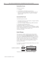
Bit/Word Definitions for the incremental encoder Module (1794-ID2)
Word
Bit
Definition
#"
,/" '1 Status for input A -2)0# 1/+0*'11#/ &'0 '1 4&#+ 0#1 '+"'!1#0 0'%+) 1 '1 Status for input B -2)0# 1/+0*'11#/ &'0 '1 4&#+ 0#1 '+"'!1#0 0'%+) 1 '1 Status for input Z -2)0# 1/+0*'11#/ &'0 '1 4&#+ 0#1 '+"'!1#0 0'%+) 1 '1 Status for input G -2)0# 1/+0*'11#/ &'0 '1 4&#+ 0#1 '+"'!1#0 0'%+) 1 '1 Status for input A -2)0# 1/+0*'11#/ &'0 '1 4&#+ 0#1 '+"'!1#0 0'%+) 1 '1 Status for input B -2)0# 1/+0*'11#/ &'0 '1 4&#+ 0#1 '+"'!1#0 0'%+) 1 '1 Status for input Z -2)0# 1/+0*'11#/ &'0 '1 4&#+ 0#1 '+"'!1#0 0'%+) 1 '1 Status for input G -2)0# 1/+0*'11#/ &'0 '1 4&#+ 0#1 '+"'!1#0 0'%+) 1 '1 Cal 0 &'0 '1 4&#+ 0#1 '+"'!1#0 1&1 !,2+1#/ &0 ##+ !)' /1#" &'0 '1 '0 /#0#1 5 )#0#1
'1 Cal 1 &'0 '1 4&#+ 0#1 '+"'!1#0 1&1 !,2+1#/ &0 ##+ !)' /1#" &'0 '1 '0 /#0#1 5 )#0#1
'1 Store 0 &'0 '1 4&#+ 0#1 '+"'!1#0 !,2+1#/ 3)2# '0 03#" '+ 01,/# &'0 '1 '0 /#0#1 5 1,/##0#1
'1 Store 1 &'0 '1 4&#+ 0#1 '+"'!1#0 !,2+1#/ 3)2# '0 03#" '+ 01,/# &'0 '1 '0 /#0#1 5 1,/##0#1
'1 Preset Reached 0 (PR0) &#+ 1&'0 '1 '0 0#1 '+ )) !,+$'%2/1',+ *,"#0 1&# !,2+1#/ 3)2# #.2)0 1&#
-/#0#1 3)2# #'1&#/ '+ -,0'1'3# ,/ +#%1'3# "'/#!1',+ &'0 '1 '0 /#0#1 5 /#0#1#0#1 +" !+ ,+)5 # 0#1
%'+ $1#/ 1 )#01 *,/# -2)0#
'1 Preset Reached 1 (PR1) &#+ 1&'0 '1 '0 0#1 '+ )) !,+$'%2/1',+ *,"#0 1&# !,2+1#/ 3)2# #.2)0 1&#
-/#0#1 3)2# #'1&#/ '+ -,0'1'3# ,/ +#%1'3# "'/#!1',+ &'0 '1 '0 /#0#1 5 /#0#1#0#1 +" !+ ,+)5 # 0#1
%'+ $1#/ 1 )#01 *,/# -2)0#
'1 ,1 20#" 0#1 1, #"
,/" '10 Store 0 3#" !,2+1#/ 3)2# ,+ !&++#) #"
,/" '10 Store 1 3#" !,2+1#/ 3)2# ,+ !&++#) #"
,/" '10 Channel 0 Current Counter Value 2//#+1 3)2# '+ !,2+1#/ #"
,/" '10 Channel 1 Current Counter Value 2//#+1 3)2# '+ !,2+1#/ #"
,/" '10 Counter 0 Readback ,2+1#/ 4,/" /#" !( )01 3)2# 4/'11#+ 1, 4/'1# 4,/" #"
,/" '10 Counter 1 Readback ,2+1#/ 4,/" /#" !( )01 3)2# 4/'11#+ 1, 4/'1# 4,/" #"
,/" '10 Revision Read '"#+1'$'!1',+ ,$ )1#01 0,$14/# 3#/0',+ !,"#
2 )'!1',+ 6 5 5–6
How Communication Takes Place and I/O Image Table Mapping with the DeviceNet Adapter
Word
Bit
Definition
Write
Word 1
0-15 (0-17)
Control 0 - Control word for setting the function of counter 0.
Bits 00-02
02
01
00
Mode Selection bits
0
0
0
Counting on positive (rising) edge of input signal A. (Up/dwn counting determined by B.)
0
0
1
Quadrature encoder X1
0
1
0
Quadrature encoder X2
0
1
1
Quadrature encoder X4
1
0
0
Counting up on the positive edge of input signal A, and down on positive edge of input signal B.
1
0
1
No count function.
1
1
0
No count function.
1
1
1
No count function.
Bit 03
Preset (Reset) bit - A positive edge on this bit moves the value in Preset X to Counter X, independent of Preset
Enable. NOTE: To use Preset as Reset, use a count value of 0000 in the Preset value word.
Bit 04
Enable Z Preset bit - When this bit is set (1), a positive edge on Z preloads Counter X = Preset X, independent of
Cal Enable. NOTE: If Z is configured to do Store and Preset (Reset), the Store will occur first.
Bit 05
Count Enable bit - When this is set (1), the incremental encoder is enabled.
Bits 06-08
(06 10)
(06-10)
Bits 09-10
(11 12)
(11-12)
Bits 11-12
(13 14)
(13-14)
Calibration Control bits - bits 06, 07 and 08
06
Enable bit - When this bit is set (1), the counter can be calibrated.
07
Direction bit - When this bit set (1), calibration is performed in a negative direction; when reset (0),
calibration is performed in a positive direction.
08
Reset bit - Calibration is acknowledged and a new calibration is enabled on a positive edge on this bit.
10
09
Gate Control bits
0
0
No gate function on input G
0
1
Counting only if G is high (active)
1
0
Counting only if G is low (inactive)
1
1
The counter can be calibrated when G is high (active).
12
11
Store Control bits
0
0
Save the counter value on the positive edge of Z (if Stored X = 0)
0
1
Save the counter value on the positive edge of G (if Stored X = 0)
1
0
Save the counter value on the negative edge of G (if Stored X = 0)
1
1
Save the counter value on the positive edge and negative edge of G (if Stored X = 0)
Bit 13 (15)
Rollover bit - When set (1), the counter counts up to the preset and then restarts at 0. If this bit is reset (0) (not
rollover), the rollover preset value = FFFF (hex = 65535 (decimal).
Bit 14 (16)
Store Reset bit - A positive edge on this bit resets Stored X in Signals.
Bit 15 (17)
Preset Reset bit - A positive edge on this bit resets Preset Detected in Signals.
Publication 1794ĆUM015B-EN-P - May 2001
How Communication Takes Place and I/O Image Table Mapping with the DeviceNet Adapter
Word
$6/8+
$46* Bit
5–7
Definition
Channel 1 Control Word 438641 ;46* ,46 7+88/3- 8.+ ,93)8/43 4, )4938+6 /87 /8
Mode Selection bits
4938/3- 43 547/8/:+ 6/7/3- +*-+ 4, /3598 7/-3'1 "5*;3 )4938/3- *+8+62/3+* (= 9'*6'896+ +3)4*+6 %
9'*6'896+ +3)4*+6 %
9'*6'896+ +3)4*+6 %
4938/3- 95 43 8.+ 547/8/:+ +*-+ 4, /3598 7/-3'1 '3* *4;3 43 547/8/:+ +*-+ 4, /3598
7/-3'1 4 )4938 ,93)8/43
4 )4938 ,93)8/43
4 )4938 ,93)8/43
/8 Preset bit - 547/8/:+ +*-+ 43 8./7 (/8 24:+7 8.+ :'19+ /3 6+7+8 % 84 4938+6 % /3*+5+3*+38 4, 6+7+8 3'(1+
/8 Preset Enable bit - $.+3 8./7 (/8 /7 7+8 ' 547/8/:+ +*-+ 43 & 56+14'*7 4938+6 % 6+7+8 % /3*+5+3*+38 4,
'1 3'(1+
/8 Count Enable bit - $.+3 8./7 /7 7+8 8.+ /3)6+2+38'1 +3)4*+6 /7 )4938/3-
/87 /87 /87 Calibration Control bits - (/87 '3* Enable bit - $.+3 8./7 (/8 /7 7+8 8.+ )4938+6 )'3 (+ )'1/(6'8+*
Direction bit - $.+3 8./7 (/8 7+8 )'1/(6'8/43 /7 5+6,462+* /3 ' 3+-'8/:+ */6+)8/43 ;.+3 6+7+8 )'1/(6'8/43 /7 5+6,462+* /3 ' 547/8/:+ */6+)8/43
Reset bit - '1/(6'8/43 /7 ')034;1+*-+* '3* ' 3+; )'1/(6'8/43 /7 +3'(1+* 43 ' 547/8/:+ +*-+ 43 8./7 (/8
Gate Control bits
4 -'8+ ,93)8/43 43 /3598 4938/3- 431= /, /7 ./-. ')8/:+
4938/3- 431= /, /7 14; /3')8/:+
'1/(6'8/43 /, /7 ./-. ')8/:+ '3* Latch Control bits
!':+ 8.+ )4938+6 :'19+ 43 8.+ 547/8/:+ +*-+ 4, & /, !846+* % !':+ 8.+ )4938+6 :'19+ 43 8.+ 547/8/:+ +*-+ 4, /, !846+* % !':+ 8.+ )4938+6 :'19+ 43 8.+ 3+-'8/:+ +*-+ 4, /, !846+* % !':+ 8.+ )4938+6 :'19+ 43 8.+ 547/8/:+ +*-+ '3* 3+-'8/:+ +*-+ 4, /, !846+* % /8 Rollover bit - $.+3 7+8 8.+ )4938+6 )49387 95 84 8.+ 56+7+8 '3* 8.+3 6+78'687 '8 , 8./7 (/8 /7 6+7+8 348
64114:+6 8.+ 64114:+6 56+7+8 :'19+ .+< *+)/2'1
/8 Store Reset bit - 547/8/:+ +*-+ 43 8./7 (/8 6+7+87 !846+* % /3 !/-3'17
/8 Store Reset bit - 547/8/:+ +*-+ 43 8./7 (/8 6+7+87 6+7+8 +').+* /3 !/-3'17
$6/8+
$46* /87 Preset 0 #'19+ 84 14'* 46 )425'6+ ;/8. )4938+6 $6/8+
$46* /87 Preset 1 #'19+ 84 14'* 46 )425'6+ ;/8. )4938+6 9(1/)'8/43 >" '= 5–8
Word
)+ +$)+,
How Communication Takes Place and I/O Image Table Mapping with the DeviceNet Adapter
Bit
Definition
Filter Selection
$- Filter A0 enable - # ( -#$, $- $, , - ( ).(- + $, $( ') *.&, ).(-$(" ,$"(& $, !$&- + 0
$"$-& &)/ *,, !$&- + /$-# , & -& !$&- + )(,-(-
$- Filter A1 enable - # ( -#$, $- $, , - ( ).(- + $, $( ') *.&, ).(-$(" ,$"(& $, !$&- + 0
$"$-& &)/ *,, !$&- + /$-# , & -& !$&- + )(,-(-
$- 2
(., $-, 2
2
Filter Constant bits - #$, )(,-(- $, )'')( -) )-# ).(- +,
% )+ '$($'.' ', *.&, /$-#
%1 )+ '$($'.' ', *.&, /$-#
%1 )+ '$($'.' ', *.&, /$-#
%1 )+ '$($'.' ', *.&, /$-#
$-, )- ., , - -) .&$-$)( 2 0 How Communication Takes Place and I/O Image Table Mapping with the DeviceNet Adapter
Defaults
5–9
Each I/O module has default values associated with it. At default,
each module will generate inputs/status and expect
outputs/configuration.
Module Defaults for:
Catalog
Number
Description
Factory Defaults
Real Time Size
Input
Default
Output
Default
Input
Default
Output
Default
Factory defaults are the values assigned by the adapter when you:
• first power up the system, and
• no previous stored settings have been applied.
For incremental encoder modules, the defaults reflect the actual
number of input words/output words. For example, for the
incremental encoder module, you have 9 input words, and 7 output
words.
You can change the I/O data size for a module by reducing the
number of words mapped into the adapter module, as shown in “real
time sizes.”
Real time sizes are the settings that provide optimal real time data to
the adapter module.
The incremental encoder modules have 15 words assigned to them.
This is divided into input words/output words. You can reduce the
I/O data size to fewer words to increase data transfer over the
backplane.
For information on using DeviceNetManager software to configure
your adapter, refer to the DeviceNetManager Software User Manual,
publication 1787-6.5.3.
5–10
How Communication Takes Place and I/O Image Table Mapping with the DeviceNet Adapter
Input, Output and
Configuration Files for Analog
Modules when used with
ControlNet
Chapter Objectives
In this chapter you will learn about:
•
•
•
•
•
•
About the ControlNet
Adapter
Communication Over the
FLEX I/O Backplane
ControlNet Adapter
I/O structure
safe state data
communication fault data
idle state behavior
input data behavior upon module removal
The FLEX I/O ControlNet adapters (cat. no. 1794–ACN15 and
–ACNR15) interfaces up to 8 FLEX I/O modules and a ControlNet
processor or scanner. The adapter can support ControlNet real–time
data connections to individual modules or module groups. Each
connection is independent of the others and can be from different
processors or scanners.
One 1794-ACN15 and -ACNR15 ControlNet adapter can interface
up to eight terminal base units with installed FLEX I/O modules,
forming a FLEX I/O system of up to eight slots. The adapter
communicates to other network system components (typically one or
more controllers or scanners, and/or programming terminals) over
the ControlNet network. The adapter communicates with its I/O
modules over the backplane.
I/O Module
Network
ControlNet
Adapter
Slot 0
I/O Module
I/O Module
Slot 1
Slot 7
Data is exchanged scheduled (when mapped) or unscheduled (using
CIO instructions).
6–2
Input, Output and Configuration Files for Analog Modules when used with ControlNet
Scheduled DataĆTransfer
Scheduled data transfer:
• is continuous
• is asynchronous to the ladder-logic program scan
• occurs at the actual rate displayed in the Actual Packet Interval
field on the programming software ControlNet I/O mapping
(monitor) screen
Unscheduled DataĆTransfer
Unscheduled operations include:
• unscheduled non-discrete I/O data transfers—through ControlNet
I/O Transfer (CIO) instructions
• peer-to-peer messaging—through Message (MSG) instructions
• messaging from programming devices
Unscheduled messaging on a ControlNet network is
non-deterministic. Your application and your configuration—number
of nodes, application program, NUT, amount of scheduled bandwidth
used, etc.—determine how much time there is for
unscheduled messaging.
Module I/O Mapping
The I/O map for a module is divided into read words and write
words. Read words consist of input and status words, and write
words consist of output and configuration words. The number of
read words or write words can be 0 or more. The length of each I/O
module’s read words and write words vary in size depending on
module complexity. Each I/O module will support at least 1 input
word or 1 output word. Status and configuration are optional,
depending on the module.
For example, a 16 point discrete input module will have up to 2 read
words and 1 write word.
ControlNet Image
# ! !
Input Size
Configuration Size
Module Image
Inputs
Not used
Not used
Delay
Time
Delay
Time
Check the I/O map for each module for the exact mapping.
! # " Input, Output and Configuration Files for Analog Modules when used with ControlNet
I/O Structure
6–3
Output data is received by the adapter in the order of the installed
I/O modules. The Output data for Slot 0 is received first, followed
by the Output data for Slot 1, and so on up to slot 7.
The first word of input data sent by the adapter is the Adapter Status
Word. This is followed by the input data from each slot, in the order
of the installed I/O modules. The Input data from Slot 0 is first after
the status word, followed by Input data from Slot 2, and so on up to
slot 7.
ControlNet Adapter
Read Data
# +.$, . ./(*. )+/. .
Network READ
(*. )+/. .
(*. )+/. .
Output Data
$ #
I/O Module I/O Module
Slot 0
Slot 1
,'.$
I/O Module
Slot 7
(*. /.+/. .
(*. /.+/. .
Network WRITE
(*. /.+/. .
Adapter Input Status Word
The input status word consists of:
• I/O module fault bits – 1 status bit for each slot
• node address changed – 1 bit (created by PLC–5 controller)
• I/O status – 1 bit (created by PLC–5 controller)
*#/($ /(. '.-
,$ .$# !0 "*).,*(($,
(*.
(*.
(*.
(*.
*. -$#
(*.
(*.
.&,*/%& (*.
(*.
'.
. .$ '.
*#$ ##,$-- & )%$# '.
The adapter input status word bit descriptions are shown in the
following table.
/!('" .'*) 1
0 6–4
Input, Output and Configuration Files for Analog Modules when used with ControlNet
Bit Description
Bit
Explanation
&'- !'. '- -$. 0&$) ) $,,*, '- #$.$".$# ') -(*. +*-'.'*) &'- !'. '- -$. 0&$) ) $,,*, '- #$.$".$# ') -(*. +*-'.'*) &'- !'. '- -$. 0&$) ) $,,*, '- #$.$".$# ') -(*. +*-'.'*) &'- !'. '- -$. 0&$) ) $,,*, '- #$.$".$# ') -(*. +*-'.'*) &'- !'. '- -$. 0&$) ) $,,*, '- #$.$".$# ') -(*. +*-'.'*) &'- !'. '- -$. 0&$) ) $,,*, '- #$.$".$# ') -(*. +*-'.'*) &'- !'. '- -$. 0&$) ) $,,*, '- #$.$".$# ') -(*. +*-'.'*) &'- !'. '- -$. 0&$) ) $,,*, '- #$.$".$# ') -(*. +*-'.'*) *#$ ##,$-- & )%$#
,$ .$# !1 "*).,*(($,
&'- !'. '- -$. 0&$) .&$ )*#$ ##,$-- -0'."& -$..')% & - !$$)
"& )%$# -')"$ +*0$, /+
. .$ ,$ .$# !1
"*).,*(($,
'. '#($
'. ,/)
*#/($ /(.
.&,/ *. /-$# -$. .* Possible causes for an I/O Module Fault are:
•
•
•
•
•
•
Safe State Data
Device Actions
transmission errors on the FLEX I/O backplane
a failed module
a module removed from its terminal base
incorrect module inserted in a slot position
the slot is empty
the slot contains a non–discrete module
The ControlNet adapter provides storage for alternate module output
data during communication faults or processor idle state. This “safe
state data” assures that a known output will be applied to the output
devices to maintain a previously designated safe operating condition
during the previously mentioned failure modes. The processor or
scanner software must include the means to specify this safe state
data for each module. If applicable, this data is sent in the
configuration block (see Image Table Mapping later in this chapter).
Device actions include:
• communication fault behavior
• idle state behavior
• input data behavior upon module removal
/!('" .'*) 2 1 Input, Output and Configuration Files for Analog Modules when used with ControlNet
6–5
Communication Fault Behavior
You can configure the adapter response to a communication fault for
each I/O module in its system. Upon detection of a communication
fault, the adapter can:
• leave the module output data in its last state (hold last state)
• reset the module output data to zero (reset)
• apply safe state data to the module output
Idle State Behavior
The ControlNet adapter can detect the state of the controlling
processor or scanner. Only 2 states can be detected: run mode, or
program mode (idle).
When run mode is detected, the adapter copies the output data
received from the processor to the corresponding module output.
When program mode is detected, the adapter can be configured to:
• leave the module output data in its last state (hold last state)
• reset the module output data to zero (reset)
• apply safe state data to the module output
Input Data Behavior upon Module Removal
I/O module input data sent by the adapter upon module removal is
configurable. The adapter can:
• reset the module output data to zero (reset)
• leave the module output data in the last state before module
removal (hold last state)
6–6
Input, Output and Configuration Files for Analog Modules when used with ControlNet
Incremental Encoder Module (1794ĆID2) Image Table Mapping
Module Image
ControlNet Files
R
PD1 PD0 S1
Input File Size
S0
C1 C0
G1
Z1
B1
A1
G0 Z0
B0
A0
Store 0 - Stored Counter Value on channel 0
*& &()
Store 1 - Stored Counter Value on channel 1
Channel 0 - current counter value
Channel 1 - current counter value
Channel 0 - Counter word readback
Channel 1 - Counter word readback
Code for identification of software version
Output File Size
Channel 0 Control Word - Sets the function of counter 0
*& &()
Channel 1 Control Word - Sets the function of counter 1
Channel 0 Preset - value to load or compare with counter 0
Channel 1 Preset - value to load or compare with counter 1
Configuration File Size
*& &()
Channel 0 Control Word - Sets the function of counter 0
Channel 1 Control Word - Sets the function of counter 1
Channel 0 Preset - value to load or compare with counter 0
Channel 1 Preset - value to load or compare with counter 1
Bit/Word Definitions for Block Transfer Read Words for the
Pulse Counter Module
Input Word
Input
p Word
0
Bit
Definition
"* Status for input A '+#) *(%)$"**( !") "* ,!% )* "%"*) )" %# * "* Status for input B '+#) *(%)$"**( !") "* ,!% )* "%"*) )" %# * "* Status for input Z '+#) *(%)$"**( !") "* ,!% )* "%"*) )" %# * "* Status for input G '+#) *(%)$"**( !") "* ,!% )* "%"*) )" %# * "* Status for input A '+#) *(%)$"**( !") "* ,!% )* "%"*) )" %# * "* Status for input B '+#) *(%)$"**( !") "* ,!% )* "%"*) )" %# * +#"*"&% . - Input, Output and Configuration Files for Analog Modules when used with ControlNet
Input Word
Bit
Definition
&0 Status for input Z ,1(/" 0.*/)&00". %&/ &0 3%"* /"0 &*!& 0"/ /&$*( 0 &0 Status for input G ,1(/" 0.*/)&00". %&/ &0 3%"* /"0 &*!& 0"/ /&$*( 0 &0 Cal 0 %&/ &0 3%"* /"0 &*!& 0"/ 0%0 +1*0". %/ ""* (&.0"! %&/ &0 &/ ."/"0 4 ("/"0
&0 Cal 1 %&/ &0 3%"* /"0 &*!& 0"/ 0%0 +1*0". %/ ""* (&.0"! %&/ &0 &/ ."/"0 4 ("/"0
&0 Store 0 %&/ &0 3%"* /"0 &*!& 0"/ +1*0". 2(1" &/ /2"! &* /0+." %&/ &0 &/ ."/"0 4 0+.""/"0
&0 Store 1 %&/ &0 3%"* /"0 &*!& 0"/ +1*0". 2(1" &/ /2"! &* /0+." %&/ &0 &/ ."/"0 4 0+.""/"0
&0 Preset Reached 0 (PR0) %"* 0%&/ &0 &/ /"0 &* (( +*#&$1.0&+* )+!"/ 0%" +1*0". 2(1" "-1(/ 0%"
,."/"0 2(1" "&0%". &* ,+/&0&2" +. *"$0&2" !&." 0&+* %&/ &0 &/ ."/"0 4 ."/"0"/"0 *! * +*(4 " /"0
$&* #0". 0 ("/0 )+." ,1(/"
&0 Preset Reached 1 (PR0) %"* 0%&/ &0 &/ /"0 &* (( +*#&$1.0&+* )+!"/ 0%" +1*0". 2(1" "-1(/ 0%"
,."/"0 2(1" "&0%". &* ,+/&0&2" +. *"$0&2" !&." 0&+* %&/ &0 &/ ."/"0 4 ."/"0"/"0 *! * +*(4 " /"0
$&* #0". 0 ("/0 )+." ,1(/"
&0 +0 1/"! /"0 0+ +.! &0/ Store 0 2"! +1*0". 2(1" +* %**"( +.! &0/ Store 1 2"! +1*0". 2(1" +* %**"( +.! &0/ Channel 0 Current Counter Value 1.."*0 2(1" &* +1*0". +.! &0/ Channel 1 Current Counter Value 1.."*0 2(1" &* +1*0". +.! &0/ Channel 0 Readback +1*0". 3+.! ."! '
+.! &0/ Channel 0 Readback +1*0". 3+.! ."! '
+.! &0/ Software identification
+.! +*0&*1"!
6–7
1(& 0&+* 5 4 6–8
Output
Word
Input, Output and Configuration Files for Analog Modules when used with ControlNet
Bit
Definition
Channel 0 Control Word - Control word for setting the function of counter 0.
Word 0
Bits 00-02
02
01
00
Mode Selection bits
0
0
0
Counting on positive (rising) edge of input signal A. (Up/dwn counting determined by B.)
0
0
1
Quadrature encoder X1
0
1
0
Quadrature encoder X2
0
1
1
Quadrature encoder X4
1
0
0
Counting up on the positive edge of input signal A, and down on positive edge of input signal B.
1
0
1
No count function.
1
1
0
No count function.
1
1
1
No count function.
Bit 03
Preset (Reset) bit - A positive edge on this bit moves the value in Preset X to Counter X, independent of Preset
Enable. NOTE: To use Preset as Reset, use a count value of 0000 in the Preset value word.
Bit 04
Enable Z Preset bit - When this bit is set (1), a positive edge on Z preloads Counter X = Preset X, independent of
Cal Enable. NOTE: If Z is configured to do Store and Preset (Reset), the Store will occur first.
Bit 05
Count Enable bit - When this is set (1), the pulse counter is enabled.
Bits 06-08
(06 10)
(06-10)
Bits 09-10
(11 12)
(11-12)
Bits 11-12
(13-14)
Calibration Control bits - bits 06, 07 and 08
06
Enable bit - When this bit is set (1), the counter can be calibrated.
07
Direction bit - When this bit set (1), calibration is performed in a negative direction; when reset (0),
calibration is performed in a positive direction.
08
Reset bit - Calibration is acknowledged and a new calibration is enabled on a positive edge on this bit.
10
09
Gate Control bits
0
0
No gate function on input G
0
1
Counting only if G is high (active)
1
0
Counting only if G is low (inactive)
1
1
The counter can be calibrated when G is high (active).
12
11
Store Control bits - These bits will trigger a Store only if the channel Store status bit (L0 or L1) is
cleared (0).
0
0
Save the counter value on the positive edge of Z (if Stored X = 0)
0
1
Save the counter value on the positive edge of G (if Stored X = 0)
1
0
Save the counter value on the negative edge of G (if Stored X = 0)
1
1
Save the counter value on the positive edge and negative edge of G (if Stored X = 0)
Bit 13 (15)
Rollover bit - When set (1), the counter counts up to the preset and then restarts at 0. If this bit is reset (0) (not
rollover), the rollover preset value = FFFF (hex = 65535 (decimal).
Bit 14 (16)
Store Reset bit - A positive edge on this bit resets Store X in Signals.
Bit 15 (17)
Preset Reset bit - A positive edge on this bit resets Preset Reached in Signals.
Publication 1794ĆUM015B-EN-P - May 2001
Input, Output and Configuration Files for Analog Modules when used with ControlNet
Output
Word
Bit
Word 1
6–9
Definition
Channel 1 Control Word - Control word for setting the function of counter 1.
Bits 00-02
02
01
00
Mode Selection bits
0
0
0
Counting on positive (rising) edge of input signal A. (Up/dwn counting determined by B.)
0
0
1
Quadrature encoder X1
0
1
0
Quadrature encoder X2
0
1
1
Quadrature encoder X4
1
0
0
Counting up on the positive edge of input signal A, and down on positive edge of input signal B.
1
0
1
No count function.
1
1
0
No count function.
1
1
1
No count function.
Bit 03
Preset bit - A positive edge on this bit moves the value in Preset X to Counter X, independent of Preset Enable.
Bit 04
Preset Enable bit - When this bit is set (1), a positive edge on Z preloads Counter X = Preset X, independent of
Cal Enable.
Bit 05
Count Enable bit - When this is set (1), the pulse counter is counting.
Bits 06-08
(06 10)
(06-10)
Bits 09-10
Bits 11-12
(13-14)
Calibration Control bits - bits 06, 07 and 08
06
Enable bit - When this bit is set (1), the counter can be calibrated.
07
Direction bit - When this bit set (1), calibration is performed in a negative direction; when reset (0),
calibration is performed in a positive direction.
08
Reset bit - Calibration is acknowledged and a new calibration is enabled on a positive edge on this bit.
10
09
Gate Control bits
0
0
No gate function on input G
0
1
Counting only if G is high (active)
1
0
Counting only if G is low (inactive)
1
1
Calibration if G is high (active) and ???
12
11
Store Control bits - These bits will trigger a Store only if the channel Store status bit (L0 or L1) is
cleared (0).
0
0
Save the counter value on the positive edge of Z (if Store X = 0)
0
1
Save the counter value on the positive edge of G (if Store X = 0)
1
0
Save the counter value on the negative edge of G (if Store X = 0)
1
1
Save the counter value on the positive edge and negative edge of G (if Store X = 0)
Bit 13
Rollover bit - When set (1), the counter counts up to the preset and then restarts at 0. If this bit is reset (0) (not
rollover), the rollover preset value = FFFF (hex = 65535 (decimal).
Bit 14
Store Reset bit - A positive edge on this bit resets Store X in Signals.
Bit 15
Store Reset bit - A positive edge on this bit resets Preset Detected in Signals.
Word 2
Bits 00-15
Preset 0 - Value to load or compare with counter 0
Word 3
Bits 00-15
Preset 1 - Value to load or compare with counter 1
Publication 1794ĆUM015B-EN-P - May 2001
6–10
Configuration
Word
Input, Output and Configuration Files for Analog Modules when used with ControlNet
Bit
Definition
Channel 0 Control Word - Control word for setting the function of counter 0.
Word 0
Bits 00-02
02
01
00
Mode Selection bits
0
0
0
Counting on positive (rising) edge of input signal A. (Up/dwn counting determined by B.)
0
0
1
Quadrature encoder X1
0
1
0
Quadrature encoder X2
0
1
1
Quadrature encoder X4
1
0
0
Counting up on the positive edge of input signal A, and down on positive edge of input
signal B.
1
0
1
No count function.
1
1
0
No count function.
1
1
1
No count function.
Bit 03
Preset (Reset) bit - A positive edge on this bit moves the value in Preset X to Counter X, independent of
Preset Enable. NOTE: To use Preset as Reset, use a count value of 0000 in the Preset value word.
Bit 04
Enable Z Preset bit - When this bit is set (1), a positive edge on Z preloads Counter X = Preset X,
independent of Cal Enable. NOTE: If Z is configured to do Store and Preset (Reset), the Store will occur
first.
Bit 05
Count Enable bit - When this is set (1), the pulse counter is enabled.
Bits 06-08
(06 10)
(06-10)
Bits 09-10
(11 12)
(11-12)
Bits 11-12
(13-14)
Calibration Control bits - bits 06, 07 and 08
06
Enable bit - When this bit is set (1), the counter can be calibrated.
07
Direction bit - When this bit set (1), calibration is performed in a negative direction; when reset (0),
calibration is performed in a positive direction.
08
Reset bit - Calibration is acknowledged and a new calibration is enabled on a positive edge on this
bit.
10
09
Gate Control bits
0
0
No gate function on input G
0
1
Counting only if G is high (active)
1
0
Counting only if G is low (inactive)
1
1
The counter can be calibrated when G is high (active).
12
11
Store Control bits - These bits will trigger a Store only if the channel Store status bit (L0 or L1)
is cleared (0).
0
0
Save the counter value on the positive edge of Z (if Latched X = 0)
0
1
Save the counter value on the positive edge of G (if Latched X = 0)
1
0
Save the counter value on the negative edge of G (if Latched X = 0)
1
1
Save the counter value on the positive edge and negative edge of G (if Latched X = 0)
Bit 13 (15)
Rollover bit - When set (1), the counter counts up to the preset and then restarts at 0. If this bit is reset (0)
(not rollover), the rollover preset value = FFFF (hex = 65535 (decimal).
Bit 14 (16)
Store Reset bit - A positive edge on this bit resets Store X in Signals.
Bit 15 (17)
Preset Reset bit - A positive edge on this bit resets Preset Detected in Signals.
Publication 1794ĆUM015B-EN-P - May 2001
Input, Output and Configuration Files for Analog Modules when used with ControlNet
Configuration
Word
Bit
Word 1
6–11
Definition
Channel 1 Control Word - Control word for setting the function of counter 1.
Bits 00-02
Bit
02
01
00
Mode Selection bits
0
0
0
Counting on positive (rising) edge of input signal A. (Up/dwn counting determined
by B.)
0
0
1
Quadrature encoder X1
0
1
0
Quadrature encoder X2
0
1
1
Quadrature encoder X4
1
0
0
Counting up on the positive edge of input signal A, and down on positive edge of
input signal B.
1
0
1
No count function.
1
1
0
No count function.
1
1
1
No count function.
Bit 03
Preset bit - A positive edge on this bit moves the value in Preset X to Counter X, independent of Preset
Enable.
Bit 04
Preset Enable bit - When this bit is set (1), a positive edge on Z preloads Counter X = Preset X,
independent of Cal Enable.
Bit 05
Count Enable bit - When this is set (1), the pulse counter is counting.
Bits 06-08
(06 10)
(06-10)
Bits 09-10
Bits 11-12
(13-14)
Calibration Control bits - bits 06, 07 and 08
06
Enable bit - When this bit is set (1), the counter can be calibrated.
07
Direction bit - When this bit set (1), calibration is performed in a negative direction; when reset (0),
calibration is performed in a positive direction.
08
Reset bit - Calibration is acknowledged and a new calibration is enabled on a positive edge on this
bit.
10
09
Gate Control bits
0
0
No gate function on input G
0
1
Counting only if G is high (active)
1
0
Counting only if G is low (inactive)
1
1
Calibration if G is high (active) and ???
12
11
Store Control bits - These bits will trigger a Store only if the channel Store status bit (L0 or L1)
is cleared (0).
0
0
Save the counter value on the positive edge of Z (if Store X = 0)
0
1
Save the counter value on the positive edge of G (if Store X = 0)
1
0
Save the counter value on the negative edge of G (if Store X = 0)
1
1
Save the counter value on the positive edge and negative edge of G (if Store X = 0)
Bit 13
Rollover bit - When set (1), the counter counts up to the preset and then restarts at 0. If this bit is reset (0)
(not rollover), the rollover preset value = FFFF (hex = 65535 (decimal).
Bit 14
Store Reset bit - A positive edge on this bit resets Store X in Signals.
Bit 15
Store Reset bit - A positive edge on this bit resets Preset Detected in Signals.
Word 2
Bits 00-15
Preset 0 - Value to load or compare with counter 0
Word 3
Bits 00-15
Preset 1 - Value to load or compare with counter 1
Publication 1794ĆUM015B-EN-P - May 2001
6–12
Input, Output and Configuration Files for Analog Modules when used with ControlNet
Calibrating Your Incremental
Encoder Module
Chapter Objective
Calibrating Your Module
In this chapter, we tell you how to set up your system to calibrate the
incremental encoder.
The incremental encoder module does not require calibration.
However, you must synchronize the module with the process you are
monitoring.
You must have your incremental encoder module installed in an
operating FLEX I/O system in order to complete synchronization.
Process calibration of the counter synchronizes the control system
with the machinery where the incremental encoder is mounted. The
counter is set to a preset value when a reference pulse is received.
Use input Z to activate calibration. The input to Z can be a zero pulse
integrated with an incremental encoder. Or input Z can come from
another transmitter independent of the pulse transmitter. Calibration
is performed at the first positive edge of input signal Z and is
independent of the signal duration.
Calibration is enabled if CalEnable = 1 or if GateControl = 3 and G
input = 1. The counter direction must coincide with CalDirection and
Calibrated must be = 0 (acknowledged by a positive edge on
CalReset). When calibration is activated, the counter is given the
value in PresetValue and Calibrated will be set. The counter value
can be saved in StoreValue if StoreControl = 0 and Stored = 0. Note
that the condition for the latch function is not dependent on the
direction and therefore does not automatically occur on that edge of
Z which activates calibration.
7–2
Calibrating Your Incremental Encoder Module
Calibration Method 1
Calibration is enabled by the flag CalEnable, which is enabled by the
control system. The preset value is copied to the counter register at a
positive edge on input Z. The old counter register value is saved in
the store register for evalution.
Calibration direction is determined by CalDirection (0 = positive
direction, 1 = negative direction).
Reset Calibrated, Stored and PresetReached after calibration with
CalReset, StoreReset and PresetReset.
CalEnable = 1
CalDirection = #%!
! % %$% !& % "&$
Calibrated = 0
#$% $%#
!
Calibrated = 1
PresetReached = 1
!& %# $%#
StoreControl = 0
Stored = 0
!& %# $%#
!
&%! ( ' Stored = 1
% $%#
Calibrating Your Incremental Encoder Module
7–3
Calibration Method 2
Calibration is enabled by input G if GateControl = 3 and Calibrated
= 0. The preset value is copied to the counter register at a positive
edge on input signal Z. The old counter register value is saved in the
store register for evalution.
Calibration direction is determined by CalDirection (0 = positive
direction, 1 = negative direction).
Reset Calibrated, Stored and PresetReached after calibration with
CalReset, StoreReset and PresetReset.
GateControl = 3
CalDirection = %' #"
# ' !'&' #("' $(!&
Calibrated = 0
%&' &'%
# PresetReached = 1
#("'% &'%
StoreControl = 0
Stored = 0
#("'% &'%
# Calibrated = 1
Stored = 1
'#% &'%
(! ' #" * ) 7–4
Calibrating Your Incremental Encoder Module
Troubleshoot the Incremental
Encoder Module
What This Chapter
Contains
Use this chapter to troubleshoot the incremental encoder module by
interpreting the indicators.
Status Indicators
The module contains indicators for each of the following:
1794-ID2
2 CH INCREMENTAL ENCODER MODULE
A
B
Z
G
+
-
C
A
B
B
Z
1
G
+
-
A
A = Power/status indicator – indicates power applied to module and
status of module.
B = Insertable label for writing individual I/O assignments.
C = Status Indicators –
A = Status of input A
B = Status of input B
Z = Status of input Z
G = Status of input G
+ = Positive count detected
– = Negative count detected
8–2
Troubleshoot the Incremental Encoder Module
Indicator
Indication
Explanation
A
Yellow
Input A active
Off
Input A not active
Yellow
Input B active
Off
Input B not active
Yellow
Input Z active
Off
Input Z not active
Yellow
Input G active
Off
Input G not active
+
Yellow
On when a positive pulse is detected; turns off
on negative pulse.
-
Yellow
On when a negative pulse is detected; turns off
on positive pulse.
OK
Red
Red during initialization after power turned on
Green
Green when initialization is completed
B
Z
G
When an input indicator (yellow) is lighted, it indicates that a valid
signal (active high or active low) is present at one of the Input
terminals.
What's Next
To find out more about the ID2 module:
See appendix A
!
"! $
# For
! ! "
Specifications - 1794ĆID2 2 Input Incremental Encoder Module
Input Specifications
!=5,/: 70 7=6</:;
!=5,/: 70 68=<; 8/: 7=6</:
368=<; * 68=< #=4;/ )3.<2 53635=5
+-2 ;316+4 -76.3<376 5=;< ,/ ;<+,4/ 07: +< 4/+;<
µ; <7 ,/ :/-7163B/.
7=6<361 :/9=/6-A
B 5+@35=5
68=< $+61/
68=< "!
+@35=5 ( .- ( .- 3635=5 ( .+@35=5 ( .3635=5 ( .-
68=< "
68=< =::/6< <A83-+4
5 ( .5 ( .5 ( .-
General Specifications
7.=4/ 7-+<376
+< !7 C& C&% C&! C&! &/:536+4
+;/
;74+<376 (74<+1/
( .-
4/@,=; =::/6<
5 ( .-
#7?/: %=884A
( .- =::/6< -76;=58<376 0:75
/@</:6+4 87?/: ;=884A
5 ( .5 ( .-
#7?/: 3;;38+<376
) 5+@35=5 ( .-
&2/:5+4 3;;38+<376
+@35=5 &'2: ( .-
6.3-+<7:; 03/4. ;3./ .:3>/6
4713- ;3./ 36.3-+<376
1://6:/. 87?/:;<+<=; 36.3-+<7:
A/447? ;<+<=; 36.3-+<7:; 4713- ;3./
/A;?3<-2 #7;3<376
35/6;376; 6-2/;
34435/</:;
@ ) @ @ @ Specifications continued on next page.
#=,43-+<376 C' !# +A A–2
Specifications
Specifications - 1794ĆID2 2 Input Incremental Encoder Module
Environmental Conditions
Operational Temperature
Shock Operating
Nonoperating
Vibration
0 to 55oC (32 to 131oF) Note: Do not connect
maximum input voltage simultaneously to all inputs
if the module ambient temperature is expected to
exceed 40oC.
-25 to 70oC (-13 to 158oF)
5 to 90% noncondensing (operating)
5 to 80% noncondensing (nonoperating)
30 g peak acceleration, 11(+1)ms pulse width
50 g peak acceleration, 11(+1)ms pulse width
Tested 2 g @ 10-500Hz per IEC 68Ć2Ć6
Input Conductors
Wire
Category
Length (max)
Belden 8761
21
1000ft (304.8m)
Storage Temperature
Relative Humidity
Agency Certification
(when product is marked)
•
•
•
•
Installation Instruction
Publication 1794Ć5.63
CUL certified
CUL listed - Class I, Division 2 Groups A, B, C, D
UL listed
CE marked for all applicable directives
1 Use this conductor category information for planning conductor routing . Refer to publication
1770Ć4.1, Industrial Automation Wiring and Grounding Guidelines for Noise Immunity."
Publication 1794ĆUM015B-EN-P - May 2001
Index
Numbers
6
1/,2 )#0&,,1 A
"-1#/ '+-21 01120 4,/" --)'!1',+0 15-'!) B
'14,/" "#$'+'1',+0 ),!( 1/+0$#/ 4/'1# '1,/" "#0!/'-1',+0 '14,/" "#0!/'-1',+0 ),!( 1/+0$#/ /#"
),!( 1/+0$#/
/#" 4/'1# ),!( 1/+0$#/ -/,%/**'+%
6
$*')5 -/,!#00,/ 6 $*')5 -/,!#00,/ ),!( 1/+0$#/ /#" 4,/" 00'%+*#+10 ),!( 1/+0$#/ 4/'1# '14,/" 00'%+*#+10 4,/" 00'%+*#+10 C
0 ,+1/,)#1 /+0$#/
'+01/2!1',+0
!,**2+'!1',+ ),!( 1/+0$#/0 !2/#+1 "/4 1&/,2%& 0# 2+'10 D
"'05!&'+'+% 4'/'+% "#$2)1 3)2#0 #3'!##1+%#/ 0,$14/# /') *,2+1'+% E
2/,-#+ +',+ '/#!1'3# !,*-)'+!# F
$/#.2#+!5 '+-21 *,"2)#
&,4 '1 4,/(0 '+-21 !- ')'1'#0 15-'!) --)'!1',+0 20'+% I
,+1/,)#1
2+0!&#"2)#" +,+6"'0!/#1# "1
1/+0$#/ 2+0!&#"2)#" ,-#/1',+0
*#00%'+% $/,* -/,%/**'+% "#3'!#0
+,+6"'0!/#1# "1 1/+0$#/ -##/61,6-##/ *#00%'+% *,"2)# $2)1 !,++#!1'+% 4'/'+% '+"'!1,/0
011#0 01120 1/,2 )#0&,,1'+% !,+0'"#/1',+0 -/#'+01))1',+ '+-21 *--'+% ,+1/,)#1 2+0!&#"2)#" +,+6"'0!/#1# "1
1/+0$#/ 2+0!&#"2)#" ,-#/1',+0
)""#/6/2+% *#00%#0 *#00%'+% $/,* -/,%/**'+% "#3'!#0
-##/61,6-##/ *#00%'+% '+-21 01120 4,/" !,*-1' )# 1#/*'+) 0#0 !,+$'%2/ )# $#12/#0 '+01))1',+ *,"2)# K
(#504'1!& -,0'1',+0 ,+1/,)#1 /+0$#/ '+01/2!1',+0
2 )'!1',+ 6 5 I–2
Index
L
* ##$/7/2,& +$00 &(,& M
+ ..(,&
7
$5 +.*$ $5.* , 1(-, $00 &$ (,01/2"1(-,0 +-#2*$ % 2*1 +-#2*$ (,01 ** 1(-, +-2,1(,& -, 1$/+(, * ! 0$ +-2,1(,& )(1 " 1 ,- 7 0 $00 &$ (,01/2"1(-,0
O
-.1(+ * #$% 2*10 P
. ,$*4 ** +-2,1(,& 7
% +(*6 ./-"$00-/ !*-") 1/ ,0%$/
./-&/ ++(,& 7 % +(*6 ./-"$00-/ !*-") 1/ ,0%$/
./-&/ ++(,& .-**$# 01/2"12/$ .-4$/ #$% 2*10 R
/$+-3(,& ,# /$.* "(,& 2,#$/ .-4$/
S
0 +.*$ ./-&/ + 7 0-%14 /$ $3("$$1 , &$/ 01 120 (,#(" 1-/0 0601$+ 1'/-2&'.21 T
1$/+(, * ! 0$0 "-+. 1(!*$ 1/-2!*$0'--1(,& 2!*(" 1(-, 7 6 U
2,0"'$#2*$# ,-,7#(0"/$1$ # 1 1/ ,0%$/
W
4 **. ,$* +-2,1(,& 4(/(,& +$1'-#0 -% 4(/(,& "-,,$"1(-,0 7
4-/# 00(&,+$,10
!*-") 1/ ,0%$/ /$ # !*-") 1/ ,0%$/ 4/(1$ AllenĆBradley
Publication Problem Report
, >4: ,/3* ' 574(1+2 </9. 4:7 *4):2+39'9/43 51+'8+ )4251+9+ '3* 7+9:73 9./8 ,472
2 Channel Incremental Encoder Module User Manual
:( '2+
'9 4
1794ĆID2/B
Check Problem(s) Type:
:( 4
1794ĆUM015B-EN-P
:( '9+
May 2001
'79 4
Describe Problem(s):
Internal Use Only
"+).3/)'1 )):7')>
9+=9
4251+9+3+88
574)+*:7+89+5
/11:897'9/43
*+,/3/9/43
/3,4 /3 2'3:'1
+='251+
-:/*+1/3+
,+'9:7+
'))+88/(/1/9>
+=51'3'9/43
49.+7
$.'9 /3,472'9/43 /8 2/88/3-
/11:897'9/43
/3,4 349 /3 2'3:'1
1'7/9>
$.'9 /8 :3)1+'7
!+6:+3)+
$.'9 /8 349 /3 9.+ 7/-.9 47*+7
9.+7 422+398
#8+ (')0 ,47 247+ )422+398
&4:7 '2+
4)'9/43.43+
+9:73 94 "+).3/)'1 422:3/)'9/438 4)0<+11 :942'9/43 11+3?7'*1+> 7/;+ '>,/+1* 98 ?
.43+ ?
% ?
:(1/)'9/43 ??:-:89 ?
NO POSTAGE
NECESSARY
IF MAILED
IN THE
UNITED STATES
BUSINESS
REPLY MAIL
FIRST-CLASS MAIL PERMIT NO. 18235 CLEVELAND OH
POSTAGE WILL BE PAID BY THE ADDRESSEE
1 ALLEN BRADLEY DR
MAYFIELD HEIGHTS OH 44124-9705
*#")"&% , + )! ' &$$ %)(
Support Services
At Allen-Bradley, customer service means experienced representatives at Customer
Support Centers in key cities throughout the world for sales service and support. Our
value-added services include:
Technical Support
•
•
•
•
SupportPlus programs
telephone support and 24-hour emergency hotline
software and documentation updates
technical subscription services
Engineering and Field Services
•
•
•
•
application engineering assistance
integration and start-up assistance
field service
maintenance support
Technical Training
•
•
•
•
lecture and lab courses
self-paced computer and video-based training
job aids and workstations
training needs analysis
Repair and Exchange Services
•
•
•
•
your only “authorized” source
current revisions and enhancements
worldwide exchange inventory
local support
55/7D;+.5/B + #8-4@/55 >=86+=387 ><37/<< 2+< ,//7 2/59371 3=< -><=86/;< 369;8?/
9;8.>-=3?3=B +7. :>+53=B 08; 68;/ =2+7 B/+;< (/ ./<317 6+7>0+-=>;/ +7. <>998;= + ,;8+.
;+71/ 80 +>=86+=387 9;8.>-=< @8;5.@3./ %2/B 37-5>./ 5813- 9;8-/<<8;< 98@/; +7. 68=387
-87=;85 ./?3-/< 89/;+=8; 37=/;0+-/< </7<8;< +7. + ?+;3/=B 80 <80=@+;/ #8-4@/55 3< 87/ 80 =2/
@8;5.< 5/+.371 =/-278581B -869+73/<
(8;5.@3./ ;/9;/</7=+=387
;1/7=37+ • ><=;+53+ • ><=;3+ • +2;+37 • /513>6 • ;+C35 • >51+;3+ • +7+.+ • 235/ • 237+ !# • 8586,3+ • 8<=+ #3-+ • ;8+=3+ • B9;>< • C/-2 #/9>,53- •
/76+;4 • ->+.8; • 1B9= • 5 $+5?+.8; • 375+7. • ;+7-/ • /;6+7B • ;//-/ • >+=/6+5+ • 87.>;+< • 871 871 • >71+;B • -/5+7. • 7.3+ • 7.87/<3+ •
;/5+7. • <;+/5 • =+5B • +6+3-+ • +9+7 • 8;.+7 • 8;/+ • >@+3= • /,+787 • +5+B<3+ • /A3-8 • /=2/;5+7.< • /@ */+5+7. • 8;@+B • !+43<=+7 • !/;> •
!23539937/< • !85+7. • !8;=>1+5 • !>/;=8 #3-8 • "+=+; • #86+73+ • #><<3+$ • $+>.3 ;+,3+ • $371+98;/ • $58?+43+ • $58?/73+ • $8>=2 0;3-+ #/9>,53- • $9+37 •
$@/./7 • $@3=C/;5+7. • %+3@+7 • %2+35+7. • %>;4/B • &73=/. ;+, 63;+=/< • &73=/. 371.86 • &73=/. $=+=/< • &;>1>+B • '/7/C>/5+ • )>18<5+?3+
55/7D;+.5/B /+.:>+;=/;< $8>=2 $/-87. $=;//= 35@+>4// ( &$ %/5 D
+A D
!>,53-+=387 D& ! +B $>9/;</./<
9>,53-+=387 D
/-/6,/; !>,53-+=387
D&
! +B 89B;312= 55/7D;+.5/B 869+7B 7- !;37=/. 37 &$