1
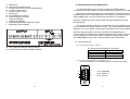
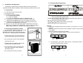
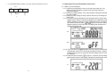
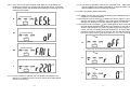
Table of Contents
1
2
3
Parallel Redundancy On-Line UPS
User’s Manual
4
5
6
Mini-J 4500 VA, 6000 VA
7
8
Advanced Power Systems GmbH & Co. KG,
Bayreuther Str. 6, D-91301 Forchheim,
Tel. +49(0)9191-7005-0, Fax +49(0)9191-7005-20
www.adpos-ups.de, [email protected]
Important Safety Instruction -----------------------------------------------------------------2
1.1
An Important Notice ------------------------------------------------------------2
1.2
Storage Instruction --------------------------------------------------------------3
Product Introduction --------------------------------------------------------------------------4
2.1
General Characteristics---------------------------------------------------------4
2.2
Symbols on the LCD Display Panel ------------------------------------------6
2.3
Panel explanation ---------------------------------------------------------------8
2.4
Communication Port Explanation------------------------------------------- 11
Installation and Operation------------------------------------------------------------------ 12
3.1
Unpacking---------------------------------------------------------------------- 12
3.2
Selecting Installation Position ----------------------------------------------- 12
3.3
Terminal Block Explanation------------------------------------------------- 13
3.4
Operation Test and Installation Instruction -------------------------------- 15
Troubleshooting Guide --------------------------------------------------------------------- 26
4.1
Trouble Shooting-------------------------------------------------------------- 26
Bundled Software Installation Guide ----------------------------------------------------- 28
5.1
Hardware Installation--------------------------------------------------------- 28
5.2
Software Installation---------------------------------------------------------- 28
Customer Options Slots -------------------------------------------------------------------- 29
6.1
All the below interface cards are with built-in EPO function. The pin
assignments of the EPO are: ---------------------------------------------------------------- 29
6.2
RSE(2nd RS-232 ) card ------------------------------------------------------ 29
6.3
RSE(RS-485) card ------------------------------------------------------------ 29
6.4
USE(USB) card --------------------------------------------------------------- 30
6.5
DCE(Dry Contact) card ------------------------------------------------------ 30
6.6
SNMP Cards ------------------------------------------------------------------- 31
6.7
The Installation of those Interface Cards ---------------------------------- 31
Hot Swappable Battery Replacement, optional------------------------------------------ 33
Specifications -------------------------------------------------------------------------------- 35
1
1
1.1.14 If liquids are split onto the UPS or foreign objects dropped into the unit,
the warranty will be null and void.
Important Safety Instruction
1.1 An Important Notice
1.1.1 To ensure safety in all applications where a UPS is hard wired to the
Electrical Supply, ensure that the system is installed by a Qualified
Electrical Contractor.
1.1.2 The UPS has its own internal energy source (battery). Should the battery
be switched on when no AC power is available, there could be voltage at
the output terminals.
1.1.3 Make sure that the AC Utility outlet is correctly grounded.
1.1.4 Do not open the case, as there are no serviceable parts inside. Your
Warranty will be void.
1.1.5 Do not try to repair the unit yourself; contact your local supplier or your
warranty will be void.
1.1.6 Please make sure that the input voltage of the UPS matches the supply
voltage.
1.1.7 Use a certified input power cable with the correct plugs and sockets for the
appropriate voltage system.
1.1.8 To eliminate any overheating of the UPS, keep all ventilation openings
free from obstruction, and do not store "things" on top of the UPS. Keep the
UPS 30 cm away from the wall.
1.1.9 Make sure the UPS is installed within the proper environment as specified.
(0-40 and 30-90% non-condensing humidity)
1.1.10 Do not install the UPS in direct sunlight. Your warranty may be void if
the batteries fail.
1.1.11 Install the UPS indoors as it is not designed for installation outdoors.
1.1.12 Dusty, corrosive and salty environments can do damage to any UPS.
1.1.13 Install the UPS away from objects that give off excessive heat and areas
that are excessively wet.
2
1.1.15 The battery will discharge naturally if the system is unused for any length
of time.
1.1.16 It should be recharged every 2-3 months if unused. If this is not done,
then the warranty will be null and void. When installed and being used, the
batteries will be automatically recharged and kept in top condition.
1.1.17 This UPS supports electronic equipment in offices, telecommunications,
process control, medical and security applications. Non-authorized
technician is not allowed to install the UPS in the following areas.
a. Medical equipment directly related to human life
b. Elevator, Metro (Subway) system or any other equipment related to
human safety.
c. Public system or critical computer systems.
1.1.18 Do not install the UPS in an environment with sparks, smoke or gas.
1.1.19 Make sure the UPS is completely turned off when moving the UPS from
one place to another. It might cause electrical shock if the output is not cut
completely.
1.1.20 The Maintenance Bypass Switch is equipped with the UPS. Please follow
the procedures strictly to switch on/off the Maintenance Bypass Switch.
1.1.21 The UPS offers CVCF (Constant Voltage Constant Frequency) setting
function.
For correct setting and wiring, please contact with your local agent.
Do not do it by yourself; otherwise, your warranty will be void.
1.1.22 This UPS has been designed and constructed to protect your assets
from the wide range of power aberrations experienced on Utility power
lines today. It is your insurance for reliable, clean and stable voltage
supply. It is worth taking care to install the system correctly and to have it
maintained correctly by your local dealer.
1.2 Storage Instruction
For extended storage through moderate climate, the batteries should be
charged for 12 hours every 3 months by plugging the UPS power cord into the
wall receptacle and turn on input breaker on front panel. Repeat this procedure
every 2 months under high temperature environment.
3
2
Product Introduction
2.1 General Characteristics
2.1.1 True online architecture continuously supplies in your critical device with a
stable, regulated, transient-free pure sine wave AC Power.
2.1.2 20KHz PWM sine-wave topology yields an excellent overall performance.
The high crest factor of the inverter handles all high-inrush current loads
without a need to upgrade the power rating.
2.1.12 Revolutionary battery management circuit analyzes battery discharging
status to adjust battery cut-off point and extend the life of batteries.
2.1.13 Intelligent temperature-controlled fan may not only extend the life of the
fan, but also reduce annoying noise because of sudden fan spin. It
remains your office quiet and comfortable as usual.
2.1.14 When UPS is out of order, you may read out the possible fault reason
from the LCD screen directly, which may reduce down unnecessary repair
task a lot.
2.1.3 Multi-functional LCD/LED panel may display various status of the UPS.
The LED display may show UPS working status, Utility Status and UPS
Abnormal status, in the mean while, the LCD display may show
Input/Output Voltage, Frequency, Load Status, Inner cabinet temperature,
and Abnormal Phenomenon.
2.1.4 To protect the unit from overloading, it automatically switches to bypass
mode in 160 seconds~ 40ms if loading is at 105%~ 150% of rating and in
case of overloading at 150% of rating, it switches to bypass mode
immediately. It will automatically switch back to inverter mode once
overload condition ceases.
2.1.5 Should the output becomes short-circuit, the UPS holds the system and
cuts the output automatically till the short circuit situation is removed
manually.
2.1.6 Should the unit become overheated, the internal thermal Switch will detect
the heat and switch to bypass mode and vice versa.
2.1.7 Fully digitalized control circuit built in the UPS may upgrade the
functionality Of the UPS as well as reach a high-level protection of the UPS.
Through powerful Communication capability built, it enhances its ability for
remote control and monitoring easily.
2.1.8 Maintenance-free sealed-type battery minimizes after-sales service.
2.1.9 Maintenance bypass switch — it provides an easy and safe
troubleshooting or maintenance function when the Utility is normal.
2.1.10 Providing four different working modes, such as Normal, ECO, CF50 and
CF60, it may widely be used in a variety of applications.
2.1.11 DC-start function makes sure of the start-up of UPS during power
outages.
4
5
2.2 Symbols on the LCD Display Panel
Item
Symbol
Description
1
LINE
Utility or Bypass Source
17
Next Page
18
Special Function Log in /out
19
Enter or Reconfirmed
20
Utility Input Normal LED
21
Bypass Input Normal LED
2
Battery Low
3
Battery Abnormal
4
UPS Overloading
5
UPS Working in specified mode*
22
UPS under Redundancy Mode
6
A Blackout Transfer occurred in UPS Output
23
UPS under ECO Mode
7
Bypass Input Abnormal, UPS fails to transfer
to bypass, Bypass Abnormal at ECO mode
24
UPS Fault or Abnormal Warning LED
8
Utility Input Abnormal
25
EPO
Emergency Power Off
UPS Shutoff
26
Er05
Battery Weak or Dead
UPS Abnormal Lock
27
Er06
Output Short Circuit
11
UPS Flow Chart
28
Er10
Inverter Over-current
12
4 Digits Measurement Display
29
Er11
UPS Overheat
13
Indicate the item desired to be measured
30
Er12
UPS Output Overloading
14
UPS ON Switch or Alarm Silence
31
Er15
Wrong Procedure to Enter Maintenance Mode
15
UPS OFF Switch
32
Er24
CVCF mode with Bypass input
16
Previous Page or Setting Change
33
Er**
Other Error code
OFF
9
10
LINE
OFF
*The specified modes include Normal mode, ECO mode, CVCF mode, etc..
6
7
2.3 Panel explanation
Go to next page
2.3.1 Front Panel Function Explanations
UPS OFF Switch
Special functions log in/out
UPS is working under ECO(Economic, Line-interactive) mode.
UPS Fault or Abnormal
2.3.2 Rear Panel Explanation
E D
C B A
I
F
J
K
G
LCD Display
L
H
Green LED lights up to indicate the UPS has the capability to run under
N
redundancy mode.
Green LED steadily lights up to indicate that the input voltage is within the
window; the LED flashes flickeringly to indicate that the input voltage is within
the acceptable window.
Green LED lights up to indicate Bypass Input is normal.
UPS ON/Alarm Silence
Go to previous page or change the setting of the UPS.
M
To re-confirm the change of UPS Setting
8
9
A
B
C
D
E
F
G
H
I
J
K
L
RS232 Port
Reserved for Parallel function
CAN Bus Connection Port for Parallel System
Customer Options Slot 1
Customer Options Slot 2
Cooling Fan
External Battery Connector
External Charger Connector
Utility Input Breaker
Bypass Input Breaker
CAM Switch(Maintenance Bypass Switch)
Input/Output Terminal Block
2.4 Communication Port Explanation
The Communication port on the UPS provides true RS232 type to
communicate with UPS software to remote monitoring the power and UPS status.
With optional interfaces cards, which contains R2E(2nd RS232 plus EPO),
RSE(RS485 plus EPO), USE(USB plus EPO), DCE(Dry Contact plus EPO), as
well as SNMP/ card, you may combine them according to your demand.
However, the R2E card, RSE card and USE card are prohibited to be used
Simultaneously.
The bundled software of the UPS is compatible with many operating systems
such as Windows 98, & 2000, ME, NT and XP. For other applications like Novell,
NetWare, Unix, Linux, please contact your local distributor for a proper solution.
When the optional interface cards are used with onboard RS232 port in
communication, the RS232 port will get the highest priority in control command,
then the shutdown command at the DCE card & also the EPO signals, then
The SNMP/WEB card, then R2E, RSE and USE get the lowest priority.
2.4.1 True RS232 type
2.4.1.1 The RS232 interface settings
M Fixing Holes for External Charger Cabinet
N Ground Position for External Battery Cabinet
The RS232 interface shall be set as follows:
Baud Rate
2400 bps
Data Length
8 bits
Stop Bit
1 bit
Parity
None
2.4.1.2 The Pin Assignments of true RS232 type
The Pin Assignments of true RS232 type are illustrated as follows:
9
8
7
6
10
5
4
3
2
1
Pin 3: RS232 Rx
Pin 2: RS232 Tx
Pin 5: Ground
11
3.3 Terminal Block Explanation
3
Installation and Operation
The packing condition and the external outlook of the unit should be
inspected carefully before installation. Retain the packing material for future use.
3.1 Unpacking
3.1.1 Take the UPS out of the PE foam.
3.1.2 Unwrap the UPS.
3.1.3 Standard Package includes:
¾ 1 set of Quick Start Manual
¾ 1 set of User's Manual
¾ 1 set of UPS communication software with RS232 cable
3.1.4. Package for the UPS with Isolation transformer & dual input:
¾ Ditto, but with additional 3pcs wire No 7 and 1pce wire No. 10.
3.1.5. Package for the UPS without isolation transformer but dual input:
¾ Ditto, but with additional 1pcs wire No. 10.
(p.s. Wire No. 7 is to be used at the input/output terminal block of the UPS.
Please refer to Chapter 3.3 for installation. Wire No. 10 is to be used at
208Vac/120Vac model only. You may consult with local agent.)
●
●
●
●
●
Remarks:
1. If the Utility and Bypass Sources are the same, you shall short L11 and L12
together.
2. When the Isolation transformer is NOT installed, the UPS output terminals will
be L22-N22.
3. When the Isolation transformer is installed:
a. For 100/110/115/120Vac system, you may connect as shown in
below.
3.2 Selecting Installation Position
It is necessary to select a proper environment
to install the unit, in order to minimize the
possibility of damage to the UPS and extend the
life of the UPS. Please follow the advice below:
N22
1. Keep at least 30cm (12 inches) clearance
from the rear panel of the UPS to the wall.
L22
N21
L21
110Vac
2. Do not block the air-flow to the ventilation
openings of the unit.
L11-N1: the terminal for Bypass Input to provide the power source when the
UPS is working under bypass mode.
L12-N1: the terminal for Utility Input to provide the power source when the
UPS is working under Utility mode.
G1: the terminal for UPS Input Ground.
L21、N21、L22、N22: the terminals for UPS Output.
G2: the terminal for UPS Output Ground.
a
0℃
40℃
3. Please check the installation site to avoid
overheat and excessive moisture.
b. For 200/100Vac, 220/110Vac, 230V/115Vac, or 240/120Vac system,
You may connect as shown in below.
N22
4. Do not place the UPS in an environment
near dust, corruptive or salty material or
flammable objects.
L22
N21
110Vac
L21
110Vac
220Vac
5. Do not expose the UPS to outdoors.
b
Relative humidly
(non condensation) 30% ~ 90%
12
13
c. For 240/208/120Vac system, you may connect as shown in below.
3.4.1 Start Up in Normal Mode
3.4.1.1 Open the terminal block cover on the rear panel (refer to 2.3.2.)
Before start the installation, please make sure the grounding is
connected properly.
3.4.1.2.Make sure Utility breaker, UPS’ Utility breaker and Bypass breaker are
On “Off” position.
3.4.1.3 Make sure the voltage of Utility matches with the input voltage window
of the UPS.
3.4.1.4 Connect the Utility separately to the terminal blocks of UPS’ Utility and
Bypass Inputs. Switch on the Power Breaker of the distribution panel
and the breakers of the UPS’ Utility and Bypass Inputs, and then the
UPS starts up. Green LEDs
&
light up to show the Utility and
Bypass Inputs are normal and the LCD display will illustrate from
drawing A to drawing B.
208Vac
N22
L22
120Va
c
N21
3.4 Operation Test and Installation Instruction
L21
120Vac
240Vac
c
A.
B.
3.4.1.5 Then, the UPS is on Bypass Mode now and it will proceed self-test
automatically. If there is no abnormal message occurred, it means the
pre-startup of the UPS is successful and the charger starts to charge
the batteries.
3.4.1.6 Press the UPS On Switch
for approx. 3 seconds, then the Buzzer
sounds twice and the LCD display changes from drawing B to drawing
C.
C
14
15
3.4.1.7 Then, the UPS is under self-test mode again, the LCD display will
illustrate from drawing C to drawing D and remain approx. 4 seconds
under battery mode, then illustrate from drawing E1 to drawing F if the
self-test is successful.
3.4.1.9 Your start-up operation of the UPS is completely now. Make sure the
UPS is plugged onto the wall receptacle for charging at least 8 hours
and the batteries of the UPS are fully charged.
3.4.2. Start-up in Battery Mode (Cold Start)
3.4.2.1 Make sure the UPS you have has already been installed at least 1
set(20pcs) of 12V/9AH batteries.
3.4.2.2 Push the UPS On Switch
to awake the UPS for approx. 3 seconds,
and then the buzzer sounds twice. The LCD display will illustrate from
drawing A to drawing G, and keep awake for approx. 10 seconds.
3.4.2.3 Press the UPS On Switch
of the UPS again for about 3 seconds till
the LCD display illustrates from drawing G to drawing H, then the UPS
will be in self-test Mode. The UPS may offer energy to the output in a
minute, and the LCD display illustrates as drawing I. In case of failure in
pushing the UPS On Switch in 10 seconds, the UPS will automatically
turn off. You then have to go through step 3.4.2.1 to 3.4.2.3 once again.
D
* It shows “test”.
E1
* It shows “OK” in self-test
G
* It shows “Off”, which means the UPS pre-start is successful.
E2
* It shows “Fail” in self-test
H
* It shows Utility input is “0” and Utility Abnormal.
F
* It shows “220Vac” in Utility Input.
I
3.4.1.8 In case of failure in self-test, the LCD display will illustrate from
Drawing D to drawing E2, then an error code or error status will be
shown on the screen.
16
17
3.4.3. Check Measured Values & Figures detected by UPS
3.4.3.1 If you would like to check the measured values & figures detected by
the UPS, please use scroll up
and scroll down
key pads.
When you use scroll down key pad, the LCD display will illustrate as
Drawing C(Voltage from Utility Input) ÆDrawing I1(Voltage from Bypass
Input) Æ Drawing J(Frequency from Utility Input) ÆDrawing
K(Frequency from Bypass Input) ÆDrawing L(UPS Output Voltage)
ÆDrawing M(UPS Output Frequency) ÆDrawing N(UPS Output Load
%)ÆDrawing O(UPS Battery Voltage) ÆDrawing P(UPS Inner
Temperature).
L
* It shows UPS output Voltage.
M
I1
* It shows UPS output frequency.
* It shows voltage comes from Bypass Input
N
* It shows UPS output load level(%)
J
* It shows frequency from Utility Input.
O
K
* It shows Battery Voltage.
* It shows frequency from Bypass Input.
P
* It shows UPS Inner Temperature
18
19
3.4.4. UPS Default Data and Special Function Execution
3.4.4.1. After UPS completely starts up, press
LCD display screen to drawing Q1.
key pad to change the
R2
* It shows self-test is “On”.
Q1
S1
* It shows buzzer “On”.
* It shows Bypass Voltage is adjusted to narrow one.
Q2
S2
* It shows buzzer “Off”.
* It shows bypass voltage is adjusted to wider one.
3.4.4.2. Press
key pad to scroll down the screen and check the UPS
settings.The LCD display will show in consequence between Drawing
Q1(buzzer) Æ Drawing R1(Self-test) ÆDrawing S1(Bypass Voltage
Windows) Æ Drawing T(Output Frequency Synchronization Window)
ÆDrawing U(Inverter Output Voltage) ÆDrawing V1(UPS Operation
Mode) ÆDrawing W(Output Voltage Micro Tune Value) ÆDrawing
X(UPS Id) ÆDrawing Y(No. of UPS in Parallel).
T
* It shows Frequency Window is +/-3Hz.
R1
U
* It shows self-test is NOT “on”.
* It shows inverter output voltage.
20
21
X
V1
* It shows UPS Identification Number.
* It shows the UPS is operated in “normal mode”.
Y
V2
st
* It shows the UPS is in the No. 1 of parallel systems.
* It shows the UPS is operated in “Eco mode”.
3.4.4.3. Press scroll up
key pad, you may execute special functions. The
Functions includes buzzer ON (as drawing Q1), or buzzer OFF (as
drawing Q2, Alarm silence for UPS Warning) and self-test ON (As
drawing R1) or self-test OFF. (as drawing R2. UPS will execute battery
test for 10 seconds. If the self-test is successful, it will show as
Drawing E1; otherwise, it will show as drawing E2 & error message in
the same time.)
V3
* It shows the UPS is operated in “CVCF 50Hz mode”.
3.4.5 UPS Default Settings and their alternatives
3.4.5.1. Make sure the UPS is not “On” yet. Press On Switch
and scroll
down
key pads simultaneously for approx. 3 seconds, the buzzer
will sound twice, the LCD display screen shows as drawing Q1, then
the UPS is under setting mode now.
V4
3.4.5.2. To scroll down the LCD screen, you may refer to Chapter 3.4.4.2.
* It shows the UPS is operated in “CVCF 60Hz mode”.
W
* It shows Output Voltage Adjustment % from 0% to 3% or -0% to -3%.
22
3.4.5.3. Except Buzzer(as drawing Q1 & Q2) and Self-test(as drawings R1 &
R2), all the rest default settings may be changed by pressing scroll up
key pad.
3.4.5.3.1. Drawings S1 and S2 mean the bypass input acceptable window, it
can be 184Vac~260Vac or 195Vac~260Vac.
3.4.5.3.2. Drawing T means the bypass frequency window of the Inverter
Output, the acceptable setting values are ±3Hz and ±1Hz.
3.4.5.3.3. Drawing U means the acceptable Inverter Output Voltage, of
which voltage is 200Vac, 208Vac, 220Vac, 230Vac, or 240Vac.
3.4.5.3.4. Drawing V1, V2, V3 and V4 mean the operation modes of the
UPS, of which alternative is Online, Eco(Economic) mode, fixed
50Hz Output or fixed 60Hz Output.
23
3.4.5.3.5. Drawing W means the adjustments of the Inverter Output, which
may be calibrated as 0%, +1%, -1%, +2%, -2%, +3%, or -3%.
3.4.5.3.6 Drawing X means a specified address & position of the UPS when
the UPS is in Parallel mode. The settable numbers are from 1st to
4th.
3.4.5.3.7. Drawing Y means the total numbers of the UPS in parallel. The
settable numbers are from 1 to 4.
3.4.5.4. When all the setting changes are done, you have to press enter
key Pad to save all the changes when the LCD screen shows as
drawing Z, then, the LCD screen will show as drawing AA to complete
the setting changes. If you don’t want to change those settings, you
may press “OFF”
key pads for 5 seconds, then the LCD screen
turns to Drawing AA directly, which means your setting changes are
invalid.
3.4.6.2. To release the UPS lock, please proceed the followings:
3.4.6.2.1. Check those error messages recorded.
3.4.6.2.2. Check to see Chapter 2.2. to trouble shoot the problem of the
UPS. Otherwise, consult your local distributor for service.
3.4.6.2.3. Press Off
key pad for 5 seconds and buzzer will sound twice.
3.4.6.2.4. Turn Off the Breaker of Utility Input.
3.4.6.2.5. The UPS lock problem is solved now, but you shall contact with
your Local distributor to make sure the error message shown is
solved.
3.4.7 Shut Off
3.4.7.1. Press Off
key pad for about 5 seconds, the Inverter output will be
turned off, then the output load is supplied by Bypass loop and the
LCD screen shows as drawing B.
3.4.7.2. Turn Off the breakers of Utility and Bypass Input.
3.4.7.3. The UPS is turned off completely.
3.4.8 Maintenance Bypass Mode
Z
* Please press Enter key to save data.
AA
* It shows the UPS is locked.
3.4.5.5. Turn Off the breaker of Utility Input.
3.4.5.6. Your Setting changes are complete.
3.4.6 UPS Is Off Due to Unknown Reason and Its Trouble Shooting
3.4.6.1 If there is a serious abnormal condition occurred, the UPS will lock it
itself in “OFF” position as shown in drawing AA and a abnormal
message will show in the LCD screen.
24
3.4.8.1. It is for UPS maintenance only. A Non-authorized technician is not
allowed to operate the following procedures. If there is any damage
under unauthorized condition, your warranty will be void immediately.
3.4.8.1.1. Press the Off
key pad for approx. 5 seconds, the LCD
screen shows as drawing B and the UPS output is on bypass
mode.
3.4.8.1.2. Release the cover of the CAM Switch(Maintenance Bypass
Switch) first, then turn on the CAM Switch to “Bypass” mode, and
at the right-hand upper Corner of the LCD screen will show
sign.
3.4.8.1.3. Turn off the UPS Utility breaker as well as Bypass Input Breaker,
you then may proceed UPS maintenance now.
3.4.8.1.4. To repeat 3.4.1.4., you may put the UPS back to normal
working mode, then turn back the CAM switch to “INV” mode,
fasten back the cover and repeat 3.4.1.5. to 3.4.1.10. The UPS
will switch back to inverter mode.
3.4.8.1.5 It is required to go through 3.4.8.1.1. first, then go through
3.4.8.1.2. If you skip 3.4.8.1.1., the UPS will alert for 10 seconds
to warn that the procedure is abnormal, which may damage the
UPS due to uncertain utility status. The UPS will switch back to
Inverter mode immediately if you turn the CAM switch back to
“INV”.
25
4
Troubleshooting Guide
Situation
UPS Red Fault LED
lights up
4.1 Trouble Shooting
When the UPS malfunctions during operation, you may check the followings:
Check Items
Check the error code
shown on the LCD
screen
1.Er05,
&
2.Er06, Er10, Er12,
Er28 &
3.EPO
4.Er11
5.Er15
6.Er24
7.other error code
a. Are the wirings of input and output correct?
b. If the input voltage of the Utility is within the input window of the UPS?
In case problems or symptoms still exist, please proceed the followings for proper
adjustment. Should the problem persists, please contact your local distributor for
help.
UPS fails to offer
battery backup or its
back up time is shorter
than its calculation.
UPS locks itself and it
can not be turned off.
26
Solution
1. Check to see if the battery
connection is properly done,
then re-charge the batteries for
8 hours to see whether the
UPS may backup normally;
otherwise, consult your local
distributor right away.
2. Remove some uncritical load
at the UPS output end. If any
damage of the coating of AC
power cord, please replace a
new one.
3. Remove the short circuit
occurred at the EPO terminal.
4. Remove the objects blocked
onto the ventilation holes.
5. Make sure the UPS is
operated normally. If it is on
CVCF mode, you have to turn
off and turn on the UPS again.
6. When the UPS is on CVCF
mode, it is prohibited to have
bypass input. You have to
turn off the UPS and bypass
input and re-start the UPS.
7. Consult your local distributor
for help.
If the backup time is still too
short after 8 hours of charge,
please contact your local
distributor for battery
replacement.
Please refer to chapter 3.4.6. to
trouble shoot the problem;
otherwise, consult your local
distributor for help.
27
5
Bundled Software Installation Guide
5.1 Hardware Installation
1. Connect the male connector of RS232 cable to the UPS communication
port.
2. Connect the female connector of the RS232 cable to a dedicated RS232
port of the computer.
3. For optional interface cards, you may refer to Chapter 6 for installation.
6
Customer Options Slots
6.1 All the below interface cards are with built-in EPO function.
The pin assignments of the EPO are:
1 Æ EPO+
2 Æ Ground
6.1.1. To enable the EPO function, please short Pin 1 & 2.
1
2
6.2 RSE(2nd RS-232 ) card
5.2 Software Installation
Please refer to the user’s manual of the software for installation.
6.2.1.
6.2.2.
6.2.3.
6.2.4.
6.2.5.
CN1 is for RS232 DB9 and CN3 is for EPO.
For communication protocol, please
refer to Chapter 2.4.1.
Installation Position: slot1 or slot 2.
Adapted flat cable: cable A or cable B
For installation, please refer to
Chapter 6.6.
6.3 RSE(RS-485) card
6.3.1.
6.3.2.
CN1 for EPO, CN2 for RS485 and CN3 for remote power.
For communication protocol, please
see the definition below:
CN2
3
2
1
1 Æ Ground
2 Æ A/Data+
3 Æ B/Data-
CN3
1
6.3.3.
6.3.4.
6.3.5.
28
2
1 Æ AC+
2 Æ AC-
Installation Position: slot1 or slot 2.
Adapted flat cable: cable A or cable B
For installation, please refer to Chapter 6.6.
29
6.4 USE(USB) card
6.6 SNMP Cards
6.4.1.
6.4.2.
CN1 for USB and CN3 for EPO.
For communication protocol, please
see the definition below:
6.4.2.1. comply with USB version 1.0,
1.5Mbps
6.4.2.2. comply with USB HID Version 1.0.
6.4.2.3. The Pin Assignments of the USE card:
1 Æ VCC (+5V)
2 Æ D-
3 Æ D+
4 Æ Ground
6.4.3.
6.4.4.
6.4.5.
Installation Position: slot1 or slot 2.
Adapted flat cable: cable A or cable B
For installation, please refer to Chapter 6.6.
6.5 DCE(Dry Contact) card
6.5.1.
The pin assignments of 10-Pin Terminal:
1 2 3 4 5 6 7 8 9 10
Pin 1: UPS on Bypass mode.
Pin 2: Utility Normal
Pin 3: Inverter On
Pin 4: Battery Low
Pin 5: Battery Bad or Abnormal
Pin 6: UPS Alarm
Pin 7: Common
Pin 8: Shutdown UPS positive(+ ) signal
Pin 9: EPO+
Pin 10: Ground
6.6.1. SNMP/WEB card
6.6.1.1 For installation,
please refer to
the user’s
manual attached
with the card. .
6.6.1.2. Installation
Position: slot1 or
slot 2.
6.6.1.3. Adapted flat
cable: cable A or cable B
6.6.1.4. For installation, please refer to Chapter 6.6.
6.6.2. Net Agent II Internal Card
6.6.2.1 For installation,
please refer to the
user’s manual
attached with the
card. .
6.6.2.2. Installation
Position: slot 2.
6.6.1.5. Adapted flat cable:
cable C.
6.6.1.6. For installation,
please refer to
Chapter 6.6.
6.7 The Installation of those Interface Cards
Make sure that the flat cable installed is the same as the one indicated below.
C
B
A
6.5.2. Installation Position: slot 1 or slot 2
6.5.3. Adapted flat cable: cable A or cable B
6.5.4. For installation, please refer to Chapter 6.6.
30
31
Please proceed the hardware installation as indicated below.
1. Remove the cover of Slot 1.
2. Slide in the selected interface card onto the Slot.
3. Fasten properly the selected interface card.
7
Hot Swappable Battery Replacement, optional
1. Unscrew the bottom of the front panel as indicated in Step. 1 as below.
2. Remove the front panel as indicated in Step 2.
1
2
3. Remove the screw of the battery pack fastener as shown in Step 3.
4. Remove the fastener as shown in Step 4.
5. Unplug the hot swappable battery connectors as shown in Step 5.
3
32
33
6. Turn the battery pack handle at 90 degree as shown in Step 6.
7. Remove the battery packs from the UPS as shown in Step 7.
8
Specifications
Model
INPUT
Voltage Window
Frequency
Phase/Wire
Power Factor
Current THD
OUTPUT
Voltage Window
Mini-J 4500
160~280Vac*
45 ~ 65 Hz
Single, Line + Neutral + Ground
Up to 0.99 at 100% Linear Load
<5% at 100% Linear Load
220/230/240Vac Selectable(208/120Vac
optional)
Voltage Adjustment
±0%; ±1%; ±2%; ±3%
Voltage Regulation
±2%
4500VA/3150W
6000VA/4200W
0.7 Lagging
Sine Wave, THD<3%(no load to full load)
Capacity
Rated Power Factor
Wave Form
Frequency Stability
±0.2%(Free Running)
±1%; ±3%
0ms
3:1
Up to 91%
Frequency Regulation
Transfer Time
Crest Factor
Efficiency(AC to AC,
Normal)
Efficiency(AC to AC, ECO)
Autonomy
DC Start
BATTERY
Type
Quantity
Voltage
Recharge Time
DISPLAY
Status On LED + LCD
Readings on LCD
Self-Diagnostics
Up to 98%
>12 min.
>8 min
Yes
Sealed Lead Acid Maintenance Free 12V/9AH
20pcs
240Vdc
4 hours to 90%
Line Mode, Backup Mode, ECO Mode, Bypass
Supply, Battery Low, Battery Bad/Disconnect,
Overload, Transferring with interruption & UPS
Fault.
Input Voltage, Input Frequency, Output Voltage,
Output Frequency, Load Percentage, Battery
Voltage & Inner Temperature.
Upon Power-on, Front Panel Setting & Software
Control, 24-hour routine checking
ALARMS
34
Mini-J 6000
35
Audible and Visual
Line Failure, Battery Low, Transfer to Bypass,
System Fault Conditions
PHYSICAL
Dimensions(WxDxH)mm
290x645x748
Input/Output Connection
Hardwire
External Battery
Plug-in & Play
Connection
Net Weight(Kgs), Standard
86/112(without isolation transformer**)
Unit/Hot Swappable unit
CE, cUL, UL
Marks
* (160~176Vac at <75% load)
** Isolation transformer: net 43kgs for 4500VA and net 53kgs for 6000VA.
36
37
38
39