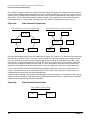
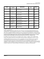
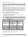
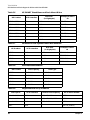
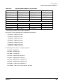
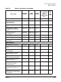
1
Communicator e3000
MPE/iX Release 7.5
(Software Release C75.00)
HP e3000 MPE/iX Computer Systems
Volume 13, Issue 1
Manufacturing Part Number : 30216-90336
E0802
U.S.A. August 2002
Notice
The information contained in this document is subject to change without notice.
Hewlett-Packard makes no warranty of any kind with regard to this material, including, but not limited to,
the implied warranties of merchantability or fitness for a particular purpose. Hewlett-Packard shall not be
liable for errors contained herein or for direct, indirect, special, incidental or consequential damages in
connection with the furnishing or use of this material.
Hewlett-Packard assumes no responsibility for the use or reliability of its software on equipment that is not
furnished by Hewlett-Packard.
This document contains proprietary information which is protected by copyright. All rights reserved.
Reproduction, adaptation, or translation without prior written permission is prohibited, except as allowed
under the copyright laws.
Restricted Rights Legend
Use, duplication, or disclosure by the U.S. Government is subject to restrictions as set forth in subparagraph
(c) (1) (ii) of the Rights in Technical Data and Computer Software clause at DFARS 252.227-7013. Rights for
non-DOD U.S. Government Departments and Agencies are as set forth in FAR 52.227-19 (c) (1,2).
Acknowledgments
UNIX is a registered trademark of The Open Group.
Hewlett-Packard Company
3000 Hanover Street
Palo Alto, CA 94304 U.S.A.
© Copyright 1997–2002 by Hewlett-Packard Company.
2
Contents
1. Overview — MPE/iX Release 7.5 (C.75.00)
Communicator Summary . . . . . . . . . . . . . . . . . . . . . . . . . . . . . . . . . . . . . . . . . . . . . . . . . . . . . . . . . . . . . . 8
Chapter 1, Overview — Communicator Summary . . . . . . . . . . . . . . . . . . . . . . . . . . . . . . . . . . . . . . . . . 8
Chapter 2, Announcements . . . . . . . . . . . . . . . . . . . . . . . . . . . . . . . . . . . . . . . . . . . . . . . . . . . . . . . . . . . 8
Chapter 3, Internet and Interoperability . . . . . . . . . . . . . . . . . . . . . . . . . . . . . . . . . . . . . . . . . . . . . . . . 8
Chapter 4, Fibre Channel Device Adapter Support on HP e3000 . . . . . . . . . . . . . . . . . . . . . . . . . . . . . 8
Chapter 5, Technical Articles . . . . . . . . . . . . . . . . . . . . . . . . . . . . . . . . . . . . . . . . . . . . . . . . . . . . . . . . . . 8
Chapter 6, Product Release History . . . . . . . . . . . . . . . . . . . . . . . . . . . . . . . . . . . . . . . . . . . . . . . . . . . . 8
Chapter 7, Catalog of User Documentation . . . . . . . . . . . . . . . . . . . . . . . . . . . . . . . . . . . . . . . . . . . . . . 9
MPE/iX Patches on HP IT Resource Center . . . . . . . . . . . . . . . . . . . . . . . . . . . . . . . . . . . . . . . . . . . . . . . 10
Features and Benefits . . . . . . . . . . . . . . . . . . . . . . . . . . . . . . . . . . . . . . . . . . . . . . . . . . . . . . . . . . . . . . 10
Access Method to the HP IT Resource Center. . . . . . . . . . . . . . . . . . . . . . . . . . . . . . . . . . . . . . . . . . . . 10
Electronic Digests . . . . . . . . . . . . . . . . . . . . . . . . . . . . . . . . . . . . . . . . . . . . . . . . . . . . . . . . . . . . . . . . . . 11
Patch Installation Tools . . . . . . . . . . . . . . . . . . . . . . . . . . . . . . . . . . . . . . . . . . . . . . . . . . . . . . . . . . . . . 11
2. Announcements
MPE/iX Release 7.5 Features . . . . . . . . . . . . . . . . . . . . . . . . . . . . . . . . . . . . . . . . . . . . . . . . . . . . . . . . . .
Hardware Platform Enhancements . . . . . . . . . . . . . . . . . . . . . . . . . . . . . . . . . . . . . . . . . . . . . . . . . . . .
External Storage and I/O Connectivity Enhancements . . . . . . . . . . . . . . . . . . . . . . . . . . . . . . . . . . . .
Internet and Interoperability. . . . . . . . . . . . . . . . . . . . . . . . . . . . . . . . . . . . . . . . . . . . . . . . . . . . . . . . .
High End Functionality . . . . . . . . . . . . . . . . . . . . . . . . . . . . . . . . . . . . . . . . . . . . . . . . . . . . . . . . . . . . .
Performance and Capacity Improvements . . . . . . . . . . . . . . . . . . . . . . . . . . . . . . . . . . . . . . . . . . . . . .
HP Announces Transition Plan for HP e3000 Server Series. . . . . . . . . . . . . . . . . . . . . . . . . . . . . . . . . .
End of Support Dates for MPE/iX Releases . . . . . . . . . . . . . . . . . . . . . . . . . . . . . . . . . . . . . . . . . . . . . . .
Software Distribution Media (6250 bpi Tapes). . . . . . . . . . . . . . . . . . . . . . . . . . . . . . . . . . . . . . . . . . . . .
HP 5000 Printers and HP e3000 A-/N-Class Support Update . . . . . . . . . . . . . . . . . . . . . . . . . . . . . . . .
Obtaining Software Security Patches for your HP Computer System . . . . . . . . . . . . . . . . . . . . . . . . . .
HP IT Resource Center Security-Related Services . . . . . . . . . . . . . . . . . . . . . . . . . . . . . . . . . . . . . . . .
Subscribing to HP IT Resource Center Security Bulletin Services . . . . . . . . . . . . . . . . . . . . . . . . . . .
Instructions . . . . . . . . . . . . . . . . . . . . . . . . . . . . . . . . . . . . . . . . . . . . . . . . . . . . . . . . . . . . . . . . . . . . . . .
If You Discover a Security Problem . . . . . . . . . . . . . . . . . . . . . . . . . . . . . . . . . . . . . . . . . . . . . . . . . . . .
13
13
13
14
14
15
16
16
17
18
19
19
19
19
20
3. Internet and Interoperability
WebWise Replaces Apache in FOS . . . . . . . . . . . . . . . . . . . . . . . . . . . . . . . . . . . . . . . . . . . . . . . . . . . . . .
System Requirements and Patches . . . . . . . . . . . . . . . . . . . . . . . . . . . . . . . . . . . . . . . . . . . . . . . . . . . .
Support . . . . . . . . . . . . . . . . . . . . . . . . . . . . . . . . . . . . . . . . . . . . . . . . . . . . . . . . . . . . . . . . . . . . . . . . . .
Product Overview and Feature Set . . . . . . . . . . . . . . . . . . . . . . . . . . . . . . . . . . . . . . . . . . . . . . . . . . . .
Migrating From Previous Versions of Apache. . . . . . . . . . . . . . . . . . . . . . . . . . . . . . . . . . . . . . . . . . . .
Introducing Sendmail for MPE/iX 7.5. . . . . . . . . . . . . . . . . . . . . . . . . . . . . . . . . . . . . . . . . . . . . . . . . . . .
System Requirements and Patches . . . . . . . . . . . . . . . . . . . . . . . . . . . . . . . . . . . . . . . . . . . . . . . . . . . .
22
22
22
22
23
25
25
4. Fibre Channel Device and Adapter Support on HP e 3000 Systems
Fibre Channel Device Adapter Support . . . . . . . . . . . . . . . . . . . . . . . . . . . . . . . . . . . . . . . . . . . . . . . . . .
Introduction. . . . . . . . . . . . . . . . . . . . . . . . . . . . . . . . . . . . . . . . . . . . . . . . . . . . . . . . . . . . . . . . . . . . . . .
SCSI-FC Router vs. Fibre Channel Adapter . . . . . . . . . . . . . . . . . . . . . . . . . . . . . . . . . . . . . . . . . . . . .
Benefits to Customers . . . . . . . . . . . . . . . . . . . . . . . . . . . . . . . . . . . . . . . . . . . . . . . . . . . . . . . . . . . . . .
31
31
31
32
3
Contents
Fibre Channel Adapter Card Supported . . . . . . . . . . . . . . . . . . . . . . . . . . . . . . . . . . . . . . . . . . . . . . . .
Fibre Channel Concepts . . . . . . . . . . . . . . . . . . . . . . . . . . . . . . . . . . . . . . . . . . . . . . . . . . . . . . . . . . . . .
Fibre Channel Adapters and Peripherals Supported. . . . . . . . . . . . . . . . . . . . . . . . . . . . . . . . . . . . . . . .
Fibre Channel Device Adapter Card . . . . . . . . . . . . . . . . . . . . . . . . . . . . . . . . . . . . . . . . . . . . . . . . . . .
Fibre Channel Devices . . . . . . . . . . . . . . . . . . . . . . . . . . . . . . . . . . . . . . . . . . . . . . . . . . . . . . . . . . . . . .
Fibre Channel Switches . . . . . . . . . . . . . . . . . . . . . . . . . . . . . . . . . . . . . . . . . . . . . . . . . . . . . . . . . . . . .
Fibre Channel Hubs . . . . . . . . . . . . . . . . . . . . . . . . . . . . . . . . . . . . . . . . . . . . . . . . . . . . . . . . . . . . . . . .
Fibre Channel Topologies Supported. . . . . . . . . . . . . . . . . . . . . . . . . . . . . . . . . . . . . . . . . . . . . . . . . . .
Cables and Connectors . . . . . . . . . . . . . . . . . . . . . . . . . . . . . . . . . . . . . . . . . . . . . . . . . . . . . . . . . . . . . .
Configuration Examples for Fibre Channel Adapters and Devices . . . . . . . . . . . . . . . . . . . . . . . . . . . .
Determining the Type of Cards in Your System . . . . . . . . . . . . . . . . . . . . . . . . . . . . . . . . . . . . . . . . . .
Determining SCSI Devices Connected to Your System . . . . . . . . . . . . . . . . . . . . . . . . . . . . . . . . . . . .
Configuring Fibre Channel Adapter Card. . . . . . . . . . . . . . . . . . . . . . . . . . . . . . . . . . . . . . . . . . . . . . .
Understanding Fibre Channel Device Paths. . . . . . . . . . . . . . . . . . . . . . . . . . . . . . . . . . . . . . . . . . . . .
Determining Fibre Channel Devices Connected to an FC Adapter Card . . . . . . . . . . . . . . . . . . . . . .
Configuring Fibre Channel Devices. . . . . . . . . . . . . . . . . . . . . . . . . . . . . . . . . . . . . . . . . . . . . . . . . . . .
Using Fibre Channel Disk as LDEV-1 . . . . . . . . . . . . . . . . . . . . . . . . . . . . . . . . . . . . . . . . . . . . . . . . . .
PDC Version Requirements for Using FC Disk as LDEV-1 . . . . . . . . . . . . . . . . . . . . . . . . . . . . . . . . .
Default Configuration Groups for Using FC Disk as LDEV-1 . . . . . . . . . . . . . . . . . . . . . . . . . . . . . . .
Upgrading from MPE/iX 7.0 to MPE/iX 7.5 with FC Disk as LDEV-1 . . . . . . . . . . . . . . . . . . . . . . . .
FCSCAN — Fibre Channel Device Scan Utility. . . . . . . . . . . . . . . . . . . . . . . . . . . . . . . . . . . . . . . . . . . .
FCSCAN Default Output . . . . . . . . . . . . . . . . . . . . . . . . . . . . . . . . . . . . . . . . . . . . . . . . . . . . . . . . . . . .
FCSCAN Output with “-n” Option. . . . . . . . . . . . . . . . . . . . . . . . . . . . . . . . . . . . . . . . . . . . . . . . . . . . .
FCSCAN Output with “-h” Option. . . . . . . . . . . . . . . . . . . . . . . . . . . . . . . . . . . . . . . . . . . . . . . . . . . . .
FCSCAN Output in Fabric Topology . . . . . . . . . . . . . . . . . . . . . . . . . . . . . . . . . . . . . . . . . . . . . . . . . . .
Fibre Channel Topology Changes . . . . . . . . . . . . . . . . . . . . . . . . . . . . . . . . . . . . . . . . . . . . . . . . . . . . .
TDUTIL — Fibre Channel Diagnostic Utility . . . . . . . . . . . . . . . . . . . . . . . . . . . . . . . . . . . . . . . . . . . . .
TDUTIL Sample Output . . . . . . . . . . . . . . . . . . . . . . . . . . . . . . . . . . . . . . . . . . . . . . . . . . . . . . . . . . . .
Using HP Support Tools Manager (STM) with Fibre Channel Adapters . . . . . . . . . . . . . . . . . . . . . . . .
HP SureStore Virtual Array 7100 on the HP e3000 . . . . . . . . . . . . . . . . . . . . . . . . . . . . . . . . . . . . . . . .
Product Brief . . . . . . . . . . . . . . . . . . . . . . . . . . . . . . . . . . . . . . . . . . . . . . . . . . . . . . . . . . . . . . . . . . . . . .
Site, Software and Hardware Requirements. . . . . . . . . . . . . . . . . . . . . . . . . . . . . . . . . . . . . . . . . . . . .
VA7100 Configuration Requirements . . . . . . . . . . . . . . . . . . . . . . . . . . . . . . . . . . . . . . . . . . . . . . . . . .
Host Hardware/Firmware Requirements . . . . . . . . . . . . . . . . . . . . . . . . . . . . . . . . . . . . . . . . . . . . . . .
Host Software Requirements . . . . . . . . . . . . . . . . . . . . . . . . . . . . . . . . . . . . . . . . . . . . . . . . . . . . . . . . .
Host Diagnostic Support . . . . . . . . . . . . . . . . . . . . . . . . . . . . . . . . . . . . . . . . . . . . . . . . . . . . . . . . . . . .
Configuring the VA7100 for Performance on the HP e3000 . . . . . . . . . . . . . . . . . . . . . . . . . . . . . . . . .
HP SCSI-FC Fabric Router for the HP e3000 . . . . . . . . . . . . . . . . . . . . . . . . . . . . . . . . . . . . . . . . . . . . .
Product Brief . . . . . . . . . . . . . . . . . . . . . . . . . . . . . . . . . . . . . . . . . . . . . . . . . . . . . . . . . . . . . . . . . . . . . .
Site, Software and Hardware Requirements. . . . . . . . . . . . . . . . . . . . . . . . . . . . . . . . . . . . . . . . . . . . .
Host Hardware/Firmware Requirements . . . . . . . . . . . . . . . . . . . . . . . . . . . . . . . . . . . . . . . . . . . . . . .
32
32
35
35
35
35
35
36
36
38
38
42
43
43
43
45
46
48
49
49
50
50
52
53
54
54
56
56
58
67
67
67
67
68
68
68
68
70
70
70
72
5. Technical Articles
Updated HP e3000 A-Class and N-Class Servers . . . . . . . . . . . . . . . . . . . . . . . . . . . . . . . . . . . . . . . . . . 76
HP Announces Availability of the HP Surestore Disk System 2300 (DS2300) for the HP e3000 . . . . . 78
HP Announces Availability of the HP Surestore Tape Array 5300 for the HP e3000 . . . . . . . . . . . . . . 79
4
Contents
HPCPUNAME Model Strings Supported With MPE/iX Release 7.5 and Possible Bootup Failures. . . 81
Model Strings Cannot be Set by Customers or by Resellers . . . . . . . . . . . . . . . . . . . . . . . . . . . . . . . . 82
SCSI Interface and Device Support for N-Class and A-Class HP e3000 . . . . . . . . . . . . . . . . . . . . . . . . 86
N-Class and A-Class Supported Devices Rules of Thumb:. . . . . . . . . . . . . . . . . . . . . . . . . . . . . . . . . . 86
SCSI Devices that will NOT be Supported on N-Class and A-Class HP e3000 . . . . . . . . . . . . . . . . . 90
HP e3000 PA-8700 A-Class and N-Class Core I/O Card . . . . . . . . . . . . . . . . . . . . . . . . . . . . . . . . . . . . . 91
Introduction. . . . . . . . . . . . . . . . . . . . . . . . . . . . . . . . . . . . . . . . . . . . . . . . . . . . . . . . . . . . . . . . . . . . . . . 91
Configuration of Console I/O Paths . . . . . . . . . . . . . . . . . . . . . . . . . . . . . . . . . . . . . . . . . . . . . . . . . . . . 91
New Default Configuration Groups . . . . . . . . . . . . . . . . . . . . . . . . . . . . . . . . . . . . . . . . . . . . . . . . . . . . 92
Secure Web Console . . . . . . . . . . . . . . . . . . . . . . . . . . . . . . . . . . . . . . . . . . . . . . . . . . . . . . . . . . . . . . . . 92
The GSP LAN/Console Port . . . . . . . . . . . . . . . . . . . . . . . . . . . . . . . . . . . . . . . . . . . . . . . . . . . . . . . . . . 92
Additional Helpful Console Information . . . . . . . . . . . . . . . . . . . . . . . . . . . . . . . . . . . . . . . . . . . . . . . . 93
Conclusion . . . . . . . . . . . . . . . . . . . . . . . . . . . . . . . . . . . . . . . . . . . . . . . . . . . . . . . . . . . . . . . . . . . . . . . . 93
SHUTDOWN — New CI Command . . . . . . . . . . . . . . . . . . . . . . . . . . . . . . . . . . . . . . . . . . . . . . . . . . . . . 94
Enhancements Summary . . . . . . . . . . . . . . . . . . . . . . . . . . . . . . . . . . . . . . . . . . . . . . . . . . . . . . . . . . . . 94
Enhancement . . . . . . . . . . . . . . . . . . . . . . . . . . . . . . . . . . . . . . . . . . . . . . . . . . . . . . . . . . . . . . . . . . . . . 94
Operation and Use of New Command . . . . . . . . . . . . . . . . . . . . . . . . . . . . . . . . . . . . . . . . . . . . . . . . . . 94
Using AUTOBOOT Feature with :SHUTDOWN;RESTART Option . . . . . . . . . . . . . . . . . . . . . . . . . . 95
Introducing Samba/iX Version 2.0.7 on MPE/iX 7.5 . . . . . . . . . . . . . . . . . . . . . . . . . . . . . . . . . . . . . . . . 99
Starting smbd and nmbd Listener Jobs . . . . . . . . . . . . . . . . . . . . . . . . . . . . . . . . . . . . . . . . . . . . . . . . 99
Starting Samba/iX Under the INETD Control . . . . . . . . . . . . . . . . . . . . . . . . . . . . . . . . . . . . . . . . . . . 99
Announcing Heartbeat High Availability Cluster/iX . . . . . . . . . . . . . . . . . . . . . . . . . . . . . . . . . . . . . . . 101
General Information . . . . . . . . . . . . . . . . . . . . . . . . . . . . . . . . . . . . . . . . . . . . . . . . . . . . . . . . . . . . . . . 101
Support Tools Manager (STM) Updated for MPE/iX 7.5 . . . . . . . . . . . . . . . . . . . . . . . . . . . . . . . . . . . . 103
New Hardware Support . . . . . . . . . . . . . . . . . . . . . . . . . . . . . . . . . . . . . . . . . . . . . . . . . . . . . . . . . . . . 103
Improved Functionality . . . . . . . . . . . . . . . . . . . . . . . . . . . . . . . . . . . . . . . . . . . . . . . . . . . . . . . . . . . . 103
Corrected Defects . . . . . . . . . . . . . . . . . . . . . . . . . . . . . . . . . . . . . . . . . . . . . . . . . . . . . . . . . . . . . . . . . 103
Program Changes . . . . . . . . . . . . . . . . . . . . . . . . . . . . . . . . . . . . . . . . . . . . . . . . . . . . . . . . . . . . . . . . . 104
Log files and Performance Problems . . . . . . . . . . . . . . . . . . . . . . . . . . . . . . . . . . . . . . . . . . . . . . . . . . 104
Predictive Support Changes in MPE/iX 7.5 . . . . . . . . . . . . . . . . . . . . . . . . . . . . . . . . . . . . . . . . . . . . . . 105
Product Overview . . . . . . . . . . . . . . . . . . . . . . . . . . . . . . . . . . . . . . . . . . . . . . . . . . . . . . . . . . . . . . . . . 105
Support for Using the Entire Disk Space on LDEV 1 . . . . . . . . . . . . . . . . . . . . . . . . . . . . . . . . . . . . . . 110
Background . . . . . . . . . . . . . . . . . . . . . . . . . . . . . . . . . . . . . . . . . . . . . . . . . . . . . . . . . . . . . . . . . . . . . . 110
Hardware and Software Requirements . . . . . . . . . . . . . . . . . . . . . . . . . . . . . . . . . . . . . . . . . . . . . . . . 110
Enhancement Details . . . . . . . . . . . . . . . . . . . . . . . . . . . . . . . . . . . . . . . . . . . . . . . . . . . . . . . . . . . . . . 110
Freeing Disk Space within 4GB. . . . . . . . . . . . . . . . . . . . . . . . . . . . . . . . . . . . . . . . . . . . . . . . . . . . . . 111
Compatibility Issues . . . . . . . . . . . . . . . . . . . . . . . . . . . . . . . . . . . . . . . . . . . . . . . . . . . . . . . . . . . . . . . 112
Before Backdating Your System. . . . . . . . . . . . . . . . . . . . . . . . . . . . . . . . . . . . . . . . . . . . . . . . . . . . . . 112
UPS Monitor/iX and UPSUTIL Enhancements . . . . . . . . . . . . . . . . . . . . . . . . . . . . . . . . . . . . . . . . . . . 113
Introduction. . . . . . . . . . . . . . . . . . . . . . . . . . . . . . . . . . . . . . . . . . . . . . . . . . . . . . . . . . . . . . . . . . . . . . 113
UPS Monitor Enhancements . . . . . . . . . . . . . . . . . . . . . . . . . . . . . . . . . . . . . . . . . . . . . . . . . . . . . . . . 113
UPSUTIL Enhancements. . . . . . . . . . . . . . . . . . . . . . . . . . . . . . . . . . . . . . . . . . . . . . . . . . . . . . . . . . . 115
RESETPFAlL Command . . . . . . . . . . . . . . . . . . . . . . . . . . . . . . . . . . . . . . . . . . . . . . . . . . . . . . . . . . . 117
For Further Information. . . . . . . . . . . . . . . . . . . . . . . . . . . . . . . . . . . . . . . . . . . . . . . . . . . . . . . . . . . . 117
AS Clause Enhancement in ALLBASE/SQL . . . . . . . . . . . . . . . . . . . . . . . . . . . . . . . . . . . . . . . . . . . . . 118
Objectives of the Enhancement . . . . . . . . . . . . . . . . . . . . . . . . . . . . . . . . . . . . . . . . . . . . . . . . . . . . . . 118
5
Contents
Usage of Column Alias Name . . . . . . . . . . . . . . . . . . . . . . . . . . . . . . . . . . . . . . . . . . . . . . . . . . . . . . .
POSIX pthread (Draft 10) APIs. . . . . . . . . . . . . . . . . . . . . . . . . . . . . . . . . . . . . . . . . . . . . . . . . . . . . . . .
Introduction. . . . . . . . . . . . . . . . . . . . . . . . . . . . . . . . . . . . . . . . . . . . . . . . . . . . . . . . . . . . . . . . . . . . . .
Current Limitations . . . . . . . . . . . . . . . . . . . . . . . . . . . . . . . . . . . . . . . . . . . . . . . . . . . . . . . . . . . . . . .
Solution Objectives . . . . . . . . . . . . . . . . . . . . . . . . . . . . . . . . . . . . . . . . . . . . . . . . . . . . . . . . . . . . . . . .
IODFAULT Generic Device IDs . . . . . . . . . . . . . . . . . . . . . . . . . . . . . . . . . . . . . . . . . . . . . . . . . . . . . . .
More Opened Files in MPE/iX Programs . . . . . . . . . . . . . . . . . . . . . . . . . . . . . . . . . . . . . . . . . . . . . . . .
Introduction. . . . . . . . . . . . . . . . . . . . . . . . . . . . . . . . . . . . . . . . . . . . . . . . . . . . . . . . . . . . . . . . . . . . . .
Current Limitation . . . . . . . . . . . . . . . . . . . . . . . . . . . . . . . . . . . . . . . . . . . . . . . . . . . . . . . . . . . . . . . .
Need for Expansion. . . . . . . . . . . . . . . . . . . . . . . . . . . . . . . . . . . . . . . . . . . . . . . . . . . . . . . . . . . . . . . .
Design Changes . . . . . . . . . . . . . . . . . . . . . . . . . . . . . . . . . . . . . . . . . . . . . . . . . . . . . . . . . . . . . . . . . .
Performance . . . . . . . . . . . . . . . . . . . . . . . . . . . . . . . . . . . . . . . . . . . . . . . . . . . . . . . . . . . . . . . . . . . . .
Compatibility Issues . . . . . . . . . . . . . . . . . . . . . . . . . . . . . . . . . . . . . . . . . . . . . . . . . . . . . . . . . . . . . . .
Limitations of Current Expansion . . . . . . . . . . . . . . . . . . . . . . . . . . . . . . . . . . . . . . . . . . . . . . . . . . . .
Conclusion . . . . . . . . . . . . . . . . . . . . . . . . . . . . . . . . . . . . . . . . . . . . . . . . . . . . . . . . . . . . . . . . . . . . . . .
Support for 2851 userlog Processes. . . . . . . . . . . . . . . . . . . . . . . . . . . . . . . . . . . . . . . . . . . . . . . . . . . . .
Current Limit . . . . . . . . . . . . . . . . . . . . . . . . . . . . . . . . . . . . . . . . . . . . . . . . . . . . . . . . . . . . . . . . . . . .
How to Increase the Limit in SYSGEN . . . . . . . . . . . . . . . . . . . . . . . . . . . . . . . . . . . . . . . . . . . . . . . .
TurboIMAGE Scalability II . . . . . . . . . . . . . . . . . . . . . . . . . . . . . . . . . . . . . . . . . . . . . . . . . . . . . . . . . . .
Data set User Label . . . . . . . . . . . . . . . . . . . . . . . . . . . . . . . . . . . . . . . . . . . . . . . . . . . . . . . . . . . . . . .
DBUTIL Change . . . . . . . . . . . . . . . . . . . . . . . . . . . . . . . . . . . . . . . . . . . . . . . . . . . . . . . . . . . . . . . . . .
Attach Enhancement in Image/SQL . . . . . . . . . . . . . . . . . . . . . . . . . . . . . . . . . . . . . . . . . . . . . . . . . . . .
Introduction. . . . . . . . . . . . . . . . . . . . . . . . . . . . . . . . . . . . . . . . . . . . . . . . . . . . . . . . . . . . . . . . . . . . . .
Why this Enhancement?. . . . . . . . . . . . . . . . . . . . . . . . . . . . . . . . . . . . . . . . . . . . . . . . . . . . . . . . . . . .
Changes in User Interface . . . . . . . . . . . . . . . . . . . . . . . . . . . . . . . . . . . . . . . . . . . . . . . . . . . . . . . . . .
Conclusion . . . . . . . . . . . . . . . . . . . . . . . . . . . . . . . . . . . . . . . . . . . . . . . . . . . . . . . . . . . . . . . . . . . . . . .
Large File Data Set (LFDS). . . . . . . . . . . . . . . . . . . . . . . . . . . . . . . . . . . . . . . . . . . . . . . . . . . . . . . . . . .
Overview . . . . . . . . . . . . . . . . . . . . . . . . . . . . . . . . . . . . . . . . . . . . . . . . . . . . . . . . . . . . . . . . . . . . . . . .
Changes . . . . . . . . . . . . . . . . . . . . . . . . . . . . . . . . . . . . . . . . . . . . . . . . . . . . . . . . . . . . . . . . . . . . . . . . .
Conversion. . . . . . . . . . . . . . . . . . . . . . . . . . . . . . . . . . . . . . . . . . . . . . . . . . . . . . . . . . . . . . . . . . . . . . .
Support for 3000 NS Servers. . . . . . . . . . . . . . . . . . . . . . . . . . . . . . . . . . . . . . . . . . . . . . . . . . . . . . . . . .
Background . . . . . . . . . . . . . . . . . . . . . . . . . . . . . . . . . . . . . . . . . . . . . . . . . . . . . . . . . . . . . . . . . . . . . .
Solution Objective . . . . . . . . . . . . . . . . . . . . . . . . . . . . . . . . . . . . . . . . . . . . . . . . . . . . . . . . . . . . . . . . .
How to Increase the Limit . . . . . . . . . . . . . . . . . . . . . . . . . . . . . . . . . . . . . . . . . . . . . . . . . . . . . . . . . .
Support for 3300 Jobs and Sessions . . . . . . . . . . . . . . . . . . . . . . . . . . . . . . . . . . . . . . . . . . . . . . . . . . . .
Background . . . . . . . . . . . . . . . . . . . . . . . . . . . . . . . . . . . . . . . . . . . . . . . . . . . . . . . . . . . . . . . . . . . . . .
Solution Objective . . . . . . . . . . . . . . . . . . . . . . . . . . . . . . . . . . . . . . . . . . . . . . . . . . . . . . . . . . . . . . . . .
How to Increase the Limit . . . . . . . . . . . . . . . . . . . . . . . . . . . . . . . . . . . . . . . . . . . . . . . . . . . . . . . . . .
118
120
120
120
120
122
124
124
124
124
124
125
125
125
125
126
126
126
127
127
127
128
128
128
128
129
130
130
130
130
131
131
131
131
132
132
132
132
6. Product Release History
Product Changes by Releases . . . . . . . . . . . . . . . . . . . . . . . . . . . . . . . . . . . . . . . . . . . . . . . . . . . . . . . . . 133
Supported Releases . . . . . . . . . . . . . . . . . . . . . . . . . . . . . . . . . . . . . . . . . . . . . . . . . . . . . . . . . . . . . . . . . 137
7. Catalog of User Documentation
MPE/iX 7.5 New or Updated Manuals . . . . . . . . . . . . . . . . . . . . . . . . . . . . . . . . . . . . . . . . . . . . . . . . . . 142
Manual Collections . . . . . . . . . . . . . . . . . . . . . . . . . . . . . . . . . . . . . . . . . . . . . . . . . . . . . . . . . . . . . . . . . 143
6
Overview — MPE/iX Release 7.5 (C.75.00)
1 Overview — MPE/iX Release 7.5 (C.75.00)
This Communicator HP e3000 provides general and detailed information on the new and enhanced
functionality for the MPE/iX Release 7.5 (C.75.00), as well as information on support, release strategy and
installation prerequisites.
This MPE/iX 7.5 Communicator describes the following enhancements:
•
MPE/iX A and N-Class Hardware Platforms
•
Native Fibre Channel Support
•
HP Surestore Tape Array 5300 and Disk System 2300 (DS2300)
•
WebWise v.2 is part of FOS
•
Sendmail is part of FOS
•
HP Predictive Support Software
•
High End Functionality (Large File Dataset, User Logging Limit Increase, IMAGE/SQL Performance
•
LDEV 1 supports more than 4GB disk Space
•
New CI Command :Shutdown, Restart
•
UPS Monitor Enhancement
Chapter 1
7
Overview — MPE/iX Release 7.5 (C.75.00)
Communicator Summary
Communicator Summary
Following are brief descriptions of the articles and chapters.
Chapter 1, Overview — Communicator Summary
This chapter provides a summary of information contained in this manual. It also provides information about
obtaining MPE patches from the HP Electronic Support Center.
Chapter 2, Announcements
Important announcements regarding availability of products and services are included in this chapter.
•
Introducing MPE/iX Release 7.5 — provides overview of 7.5 enhancements.
•
End of Support dates for MPE/ix Release 6.0 (extended to December 31, 2002) and 6.5 (extended to
December 31, 2003)
•
Software Distribution Media (6250 bpi Tapes) discontinued.
•
HP 5000 Printer and HP e3000 A/N-Class Support Update — provides a listing of printer devices NOT
supported on A/N-class Servers.
•
Obtaining Software Security Patches for you HP Computer System — provides
Chapter 3, Internet and Interoperability
This chapter contains articles about updated Webwise and Sendmail.
Chapter 4, Fibre Channel Device Adapter Support on HP e3000
This chapter contains technical articles about the following: Fibre Channel Adapters and peripherals,
configuration examples for Fibre Channel Adapters and devices, Fibre Channel Device Scan Utility, TDUtil,
and HP Support Tools Manager.
Chapter 5, Technical Articles
This chapter contains the following: Updated HP e3000 A/N-Class Servers, HP Surestore Disk System 2300,
HP Surestore Tape Array 5300, SCSI interface and Device Support for A/N-Class HP e3000, HP e3000
PA-8700 A/N-Class Core I/O Card, SHUTDOWN—New CI Command, Samba/IX Version 2.0.7, Heartbeat
High Availability Cluster/iX, Updated Support Tools Manager, Support for using the entire disk space on
LDEV1, UPS Monitor/iX and UPSUTIL enhancements, AS Clause enhancement in ALLBASE/SQL, POSIX
pthread (Draft 10) APIs, OIDFAULT Generic Device IDs, Support for 2851 userlog processes, TurboIMAGE
Scalability II, Attach enhancement in ImageSQL, Large File Data Set, HP Surestore Virtual Array 7100, HP
SCSI-FC Fabric Router for the hp e3000.
Chapter 6, Product Release History
This chapter provides information on product release history.
8
Chapter 1
Overview — MPE/iX Release 7.5 (C.75.00)
Communicator Summary
Chapter 7, Catalog of User Documentation
This chapter provides a listing of all new or updated manuals at the time of the MPE/iX7.5 Release.
Chapter 1
9
Overview — MPE/iX Release 7.5 (C.75.00)
MPE/iX Patches on HP IT Resource Center
MPE/iX Patches on HP IT Resource Center
by Patch Support Team
Commercial Systems Division
MPE/iX patches for MPE/iX Releases are available on the IT Resource Center (previously the HP Electronic
Support Center) to all customers.
Features and Benefits
The new patch access and delivery system benefits all MPE/iX customers with:
•
Improved overall communication between HP and customers.
•
Provision of useful and timely information for patch justification and decision making.
•
Reduced system downtime for known problems.
•
Reduction of the turnaround time for patch availability and delivery.
•
Close to 24*7 access time.
•
Unification of the MPE/iX and HP-UX patch delivery process.
Electronic access to patch information and delivery of patches provide three basic services:
1. Access to patch information in an automated, timely and accurate manner.
2. Electronic downloading of patch information and binaries.
3. Proactive notification of new patches via email.
Access Method to the HP IT Resource Center
To serve customers the IT Resource Center provides World Wide Web access for downloading patches.
Access to World Wide Web Server (www)
IT Resource Center is available through the World Wide Web.World Wide Web access is the easiest, fastest,
and most popular method of browsing for patch information and downloading patches. It is more reliable,
especially for large patches.
•
U.S. Web accessing address:
http://us-support.external.hp.com
•
European Web accessing address:
http://europe-support.external.hp.com
10
Chapter 1
Overview — MPE/iX Release 7.5 (C.75.00)
MPE/iX Patches on HP IT Resource Center
Electronic Digests
If you want to keep yourself up-to-date on the latest development of MPE/iX patches, you can sign up for the
daily Security Bulletin and weekly mpeix_patch Bulletin. Once you have subscribed to these two bulletins,
you will receive these digests on a periodic basis via electronic mail. HP IT Resource Center will inform you
proactively about newly developed security and GR patches. For more information, refer to the instructions on
the IT Resource Center website.
Patch Installation Tools
There are two tools available to install MPE/iX reactive patches, Patch/iX and AUTOPAT. HP recommends the
use of Patch/iX for reactive patch installation. Patch/iX has many features and checks to ease and improve the
installation process, including:
•
A sophisticated patch qualification mechanism to ensure the integrity of your system.
•
The ability to perform much of the patch installation process while your system is still up and available to
users.
•
An option to install a patch or set of patches using the HP Stage/iX Subsystem, which allows the
application of a patch to be performed without tapes. For more information on Stage/iX, refer to the
System Software Maintenance Manual for your release. Patch/iX instructions are also available on the
following website: http://www.docs.hp.com/mpeix/
You should use AUTOPAT only if you are familiar with its use, and have a good understanding of MPE/iX patch
management.
Patch/iX Installation Document Retrieval
These are the steps for retrieving documents using Patch/iX.
1. Access the HP IT Resource Center WEB site (previously the Electronic Support Center) using the
appropriate WEB address for your country.
2. Click on the link, “Individual Patches.”
3. Enter: “ITRC User ID” and “password.”
4. Click on the link, “MPE/iX Patches.”
5. Click on the link, “MPE Patch Installation Guide.”
6. Click on the link, “Use Patch/iX or AUTOPAT to install the patch.”
7. Click on the link, “Patch/iX Instructions.”
Patch/iX Version Identification
To ensure you have the latest version of Patch/iX, on your system do the following:
1. :HELLO MANAGER.SYS,INSTALL
2. :PATCHIX VERSION
3. Compare this version number (for example, B.01.02) with the latest version available for your release on
the HP IT Resource Center Patch/iX download page. If you are running an earlier version than is
available, you should download and install the newer one from the download page.
Chapter 1
11
Overview — MPE/iX Release 7.5 (C.75.00)
MPE/iX Patches on HP IT Resource Center
AUTOPAT Installation Document Retrieval
AUTOPATINST is the “DOCID” of the document with instructions to assist you in installing one or more patches
needed by your MPE/iX system using the AUTOPAT installation tool.
1. Access the HP IT Resource Center WEB site (previously the Electronic Support Center) using the
appropriate WEB address for your country.
2. In the Main Menu, Click on the link, “Search Technical Knowledge Base.”
3. Enter: “ITRC User ID” and “password.”
4. In the Technical Knowledge Base Home page from the pull down menu, Click on “Search By DOC ID” (do
not Search by Keyword).
5. In the search field, enter “AUTOPATINST.”
6. Click on the “SEARCH” button.
Create a CSLT Prior to Patch Installation
Before starting any patch application activity, you should always back up your system by creating a Custom
System Load Tape and a full backup. This will allow you the flexibility of restoring your system to the
previous environment. To create a CSLT, do the following:
1. Log on as MANAGER.SYS
2. :SYSGEN
3. >TAPE
Disclaimer
CAUTION
12
Hewlett-Packard is not liable for errors occurring during data transmission through the
Internet. HP assumes no responsibility for the use or reliability of its software on equipment
that it has not furnished itself. Furthermore, for customers without a current support contract
with HP, HP is not responsible for answering any questions in regard to the use of this patch
delivery process.
Chapter 1
Announcements
MPE/iX Release 7.5 Features
2 Announcements
MPE/iX Release 7.5 Features
MPE/iX Release 7.5 is designed to further enhance our HP e3000 product offering that capitalizes on the PCI
architecture of the A- and N-Class systems running MPE/iX. These enhancements provide additional
functionality, increased performance and connectivity advancements
MPE/iX Release 7.5 enables the new A- and N-Class systems to higher speed and performance as provided by
the new PA-8700 processors. Further, this release provides new functionality to these systems, such as Native
Fibre Channel Support, new storage devices, increases in user logging limits, ability to access LDEV 1 disk
space beyond 4 GB, and many other system enhancements designed to help MPE/iX and HP e3000 customers.
MPE/iX Release 7.5 features include the following:
Hardware Platform Enhancements
PA-8700 N-Class
For our mid-range and high-end customers, MPE/iX Release 7.5 supports up to a 4-way PA-8700-based
N-Class system. The PA- 8700-based N-Class has the same configuration limits, supported peripherals and
supported interface cards as on 7.0 Express 1. In addition, MPE/iX 7.5 provides many Fibre Channel features.
PA-8700 A-Class
For our low-end customers, MPE/iX Release 7.5 supports the PA-8700-based A-Class systems. The
PA-8700-based A-Class has the same configuration limits, supported peripherals and supported interface
cards as on 7.0 Express 1. In addition, MPE/iX 7.5 provides many Fibre Channel features.
External Storage and I/O Connectivity Enhancements
Native Fibre Channel Support
With MPE/iX Release 7.5, support has been introduced for the PCI 2GBs Fibre Channel Device Adapter card
(A6795A) on A- and N-Class HP e3000 systems. This adapter card provides the ability to connect a fibre
channel device directly to the HP e3000 system using fibre channel cables. The 2 GB/s FC card is supported
with the VA7100 and XP512 Fibre Channel disk arrays on MPE/iX 7.5. Prior to MPE/iX 7.5, HP e3000
systems supported connectivity to Fibre Channel devices through the HP SCSI-Fibre Channel Router, which
was connected to a PCI-SCSI adapter card. The router will continue to be available for those customers who
choose to remain on MPE/iX 7.0.
HP Surestore Tape Array 5300
The HP Surestore Tape Array 5300 is a 3U rack enclosure that will hold a variety of full-height and
half-height tape drives (DDS3, DDS4 and DLT8000), providing a truly flexible storage solution for use in a
variety of different data storage situations. This device is also supported on MPE/iX 7.0 Express 1.
Chapter 2
13
Announcements
MPE/iX Release 7.5 Features
HP Surestore Disk System 2300 (DS2300)
The HP DS2300 is a 3U, 14-LP-disk, Ultra160 enclosure. Redundant hot-swappable components ensure
system uptime. Mixed disk environment support, flexible deployment options, and upgradability to Ultra320
protect your investment. This device is also supported on MPE/iX 7.0 Express 1.
Internet and Interoperability
WebWise v.2 part of FOS
The current Apache web server in FOS has been replaced by the HP WebWise MPE/iX Secure Web Server
which is built from recent versions of Apache, mod_ssl, and OpenSSL. In addition to the security related
features of X.509 authentication and SSL transport encryption, there are new Apache features and bug fixes
that have come out since 1.3.14.
SIB Item #4- Sendmail in FOS
The Sendmail MTA (Mail Transport Agent) is now included in FOS to facilitate the sending and receiving of
e-mail. The functionality supported is comparable to the Sendmail functionality of HP-UX.
ODBC and JDBC Continue to be the Prime Database Connectivity
Updated ODBC access is provided via MB Foster Associates, ODBC/Link SE and is bundled at no additional
cost with IMAGE/SQL and ALLBASE/SQL.
High End Functionality
Large File Dataset
Each dataset in a TurboIMAGE database is an MPE file. The maximum size of a dataset file was 4 GB. For
dataset size greater than 4GB, TurboIMAGE used a set of files residing in HFS domain to store the data,
called a JUMBO dataset. With the Large File Dataset enhancement, TurboIMAGE allows users to use MPE
large file instead of JUMBO files as dataset files.
User Logging Limit Increase
With this solution, a single user level process can access 2851 user logging concurrently. This is improved
from the current user-logging limit of 1140.
IMAGE/SQL Performance
IMAGE product performance increases by adding two new options to the Attach command: NOAUTO and
NOAUTOSPLIT.
HP Predictive Support Software
Predictive provides proactive hardware support and helps increase the uptime of your systems by monitoring
system memory and disk/tape drives. When Predictive detects a potential problem, it sends a message to the
HP Response Center. The Response Center portion of the system screens the data and forwards problems
requiring further analysis to a Response Center Engineer. If action is needed at your site, the Response
Center Engineer and a Customer Engineer work with you to resolve the problem. This proactive hardware
support is provided as part of your HP Hardware and Software Support Services Agreement.
14
Chapter 2
Announcements
MPE/iX Release 7.5 Features
Performance and Capacity Improvements
LDEV 1 Now Supports more than 4GB Disk Space
Prior to Release 7.5, MPE/iX supported and used only 4GB of disk space of LDEV 1 disk, even though the
physical disk itself had more than 4GB disk space (such as 18GB, 36GB, 73GB) With the enhancement, the
limitation on LDEV 1 using only 4GB is now removed so that LDEV 1 can use up to the maximum capacity of
the physical disk.
New CI Command :Shutdown, Restart
This enhancement provides a shutdown mechanism with a reboot option in the command level similar to the
HP-UX operating system. This enhancement provides a :SHUTDOWN command on the CI prompt, with a
RESTART option, which shuts down the system completely and, optionally, reboots automatically.
UPS Monitor Enhancement
This enhancement allows user-controlled system shutdown when the UPS reports that incoming AC power
has failed. The MPE/iX UPS Monitor software is now a part of FOS and has been enhanced to permit a
System Manager to instruct the UPS device.
Chapter 2
15
Announcements
HP Announces Transition Plan for HP e3000 Server Series
HP Announces Transition Plan for HP e3000 Server Series
In November 2001, Hewlett-Packard began advising customers to transition from HP e3000 servers to other
HP server platforms over the next five years. The rapid evolution of technology away from proprietary
platforms and customer and partner decisions to move to other platforms led to the transition plan.
HP is offering customers assistance for their transition, including migration services, financing options,
consulting, outsourcing and education. Customers with newer HP e3000 servers will be able to convert them
to HP-UX servers at no cost. Trade-in credits and discounts toward the purchase of the latest HP servers
running HP-UX, Microsoft Windows or Linux also will be available. In addition, HP is working with e3000
application providers to transition their applications and then their customer bases to other HP platforms.
To ensure customers have time to plan any final server purchases, HP will continue to sell HP e3000 servers
until November 1, 2003. During that time, HP plans to provide enhancements, including new processors and
storage solutions.
HP also will provide a broad portfolio of support services for the e3000 servers until January 1, 2007. This
support is designed to ensure that customers have time to plan and execute a transition to an alternative HP
server platform.
HP is working with a number of tools, middleware and sustem integration partners to offer additional
migration tools and services. A comprehensive program is being designed to track the tools and services
available and to create linkages between partners to offer customer complete migration solutions. Partners
cam find more information on HP’s partner Web site at http://www.hp.com/dspp/ or they may sign up for
the partner-transition program at http://www.hp.com/go/developers.
For more details on the HP announcement, please visit http://www.hp.com/go/e3000.
End of Support Dates for MPE/iX Releases
Support for the MPE/iX Release 6.0 release has been extended to December 31, 2002. Support for MPE/iX
Release 6.5 has been extended to December 31, 2004. MPE/iX release 7.0 and 7.5 will be supported until
December 31, 2006.
Customers on releases 6.0 or 6.5 should plan to update to either MPE/iX 7.0 or MPE/iX 7.5 prior to these
dates. We would encourage most customers to update to the 7.5 or 7.0 Express 1 release since these releases
contain many performance and capacity enhancements for high-end systems, and bundled tools for using the
HPe3000 with the Internet. Additionally, 7.0 and 7.5 releases will be supported longer than the 6.5 release.
As we have done for previous MPE/iX releases, Hewlett-Packard will continue to provide 18 months notice
before terminating support of a given release.
16
Chapter 2
Announcements
Software Distribution Media (6250 bpi Tapes)
Software Distribution Media (6250 bpi Tapes)
Hewlett-Packard has stopped using 6250 bpi tapes for the distribution of HP software with the shipment of
MPE/iX Release 7.0. Customers can no longer sign up for 6250 bpi software distribution media. Customers
with existing contracts that call for 6250 bpi tapes will still receive these tapes for releases prior to MPE/iX
Release 7.0, but all customers are encouraged to update their contracts to use either DDS or CDs as their
software distribution media.
The 6250 bpi tape drives will still be supported for customer usage. HP simply has stopped distributing
software using this media.
Chapter 2
17
Announcements
HP 5000 Printers and HP e3000 A-/N-Class Support Update
HP 5000 Printers and HP e3000 A-/N-Class Support Update
In the April, 2001 HP e3000 Business Servers Configuration Guide and the MPE/iX 7.0 Communicator, it
was incorrectly stated that the HP 5000 Fanfold Printers were supported on the HP e3000 A-/N-Class
Servers. The following SCSI Printer Devices are NOT supported on HP e3000 A-/N-Class Servers:
C2753A Model F100 printer — 208 V, 60 Hz power
C2753B Model F100 Turbo printer — 208 V, 60 Hz
C2754A Model F100 printer — 230/400 V, 50 Hz
C2754B Model F100 Turbo printer — 230/400V, 50Hz
C2755B Model F135XP printer; 208 V, 60 Hz power
C2756B Model F135XP printer — 230/400 V, 50 Hz
C2772A Model F100XP printer — 208 V, 60 Hz power
C2773A Model F100XP printer — 230/400 V, 50 Hz
C2776A Model F135 printer — 208 V, 60 Hz power
C2777A Model F135 printer — 230/400 V, 50 Hz
These printers will continue to be supported, through their end of support life, December 1, 2002, when
connected to S900 (9x8, 9x9, 99x) HP e3000 systems.
The HP 5000 Cut Sheet Printers are supported on the HP e3000 A/N-Class Servers.
18
Chapter 2
Announcements
Obtaining Software Security Patches for your HP Computer System
Obtaining Software Security Patches for your HP Computer System
Hewlett-Packard would like to make you aware of a special free service provided for all customers of HP
e3000 and HP 9000 computer systems. This service gives customers a direct route to Hewlett-Packard for
obtaining information relating to the security of their Hewlett-Packard Computer System(s).
Hewlett-Packard issues information on the availability of Software security patches via Security Bulletins to
subscribers of the HP Security Bulletin Digest e-mail service, a part of the IT Resource Center (formerly the
HP Electronic Support Center). A Hewlett-Packard support contract is NOT required to subscribe to this
service to obtain information or security patches. Any purchaser of an HP e3000 or HP 9000 Computer
System can make use of the HP Security Bulletin services at no charge.
Customers may also obtain information and Security Bulletin services via the World Wide Web.
A security problem is a software defect that allows unauthorized personnel to gain access to a Computer
System or to circumvent any of the mechanisms that protect the confidentiality, integrity or availability of the
information stored on the system. When such problems in Hewlett-Packard software are brought to the
attention of the company, their resolution is given a very high priority. This resolution is usually in the form
of a Security Bulletin which may explain how to correct the problem or describe how to obtain a software
security patch that will correct the problem.
Hewlett-Packard has introduced this service as the primary mechanism to alert subscribers to security
problems and provide corrections. Hewlett-Packard will not analyze the relevance of any security patch to any
individual customer site within the scope of the HP Security Bulletin service. The responsibility for obtaining
and applying security patches resides with the customer.
The remainder of this letter outlines the various security related services offered by Hewlett-Packard IT
Resource Center and the methods for subscribing to and retrieving information from it. It also outlines how
you can inform Hewlett-Packard of potential security concerns you may have with your Hewlett-Packard
Computer System.
HP IT Resource Center Security-Related Services
HP IT Resource Center offers subscribers the following benefits:
•
Receive Security Bulletins automatically when they are published.
•
Retrieve the archive list of bulletins issued prior to subscription.
•
Download security patches if the subscriber configuration supports it.
Remember, an HP support contract is not required to subscribe to HP Security Bulletin services.
Subscribing to HP IT Resource Center Security Bulletin Services
Once you have placed your name on the subscriber list for future Security Bulletins (see instructions below),
you will receive them via e-mail on the day they are issued by HP.
As referenced below, you can also view a list of past Security Bulletins issued in the “HP Security Bulletins
Archive.”
Instructions
To subscribe to automatically receive future NEW HP Security Bulletins from the Hewlett-Packard Electronic
Support Center via electronic mail, do the following (instructions subject to change without notice):
Chapter 2
19
Announcements
Obtaining Software Security Patches for your HP Computer System
1. Use your browser to access the HP IT Resource Center web page at:
http://us-support.external.hp.com
US, Canada, Asia-Pacific,
and Latin-America
http://europe-support.external.hp.com
Europe
2. Logon with your User ID and password (or register for one). Remember to save the User ID assigned to
you, and your password.
3. Once you are on the Hewlett-Packard IT Resource Center home page, click on “Support Information
Digests.” On this page, you can subscribe to many different digest services, including the Security
Bulletin Digests.
To review Security Bulletins that have already been released, click on “Search Technical Knowledge Base
(Security Bulletins only)” on the HP Electronic Support Center home page. Near the bottom of the next page,
click on “Browse the HP Security Bulletins Archive.”
Once in the archive, click on “HP-UX Security Patch Matrix” to get a patch matrix of current HP-UX and BLS
security patches. Updated daily, this matrix categorizes security patches by platform/OS release, and by
Security Bulletin topic.
If You Discover a Security Problem
To report new security vulnerabilities, send e-mail to
[email protected]
Please encrypt any explicit information using the security-alert PGP key, available from your local key server,
or by sending a message with a -subject- (not body) of ‘get key’ (no quotes) to [email protected].
20
Chapter 2
Internet and Interoperability
3 Internet and Interoperability
This chapter contains the following articles:
•
WebWise replaces APACHE in FOS
•
Introducing Sendmail for MPE/iX 7.5
Chapter 3
21
Internet and Interoperability
WebWise Replaces Apache in FOS
WebWise Replaces Apache in FOS
By Mark Bixby, Commercial Systems Division
The HP WebWise MPE/iX Secure Web Server version A.01.00 was first introduced as a separately
purchasable add-on product for MPE/iX 6.5 or greater. But as of MPE/iX 7.5, the WebWise web server has
been updated to version A.03.00 and replaces Apache in FOS as a no-extra-cost bundled product.
This is the second release of the HP WebWise MPE/iX Secure Web Server. It was labeled version A.03.00
because it is replacing the A.02.00 version of Apache. There was no A.02.00 version of WebWise.
HP WebWise MPE/iX Secure Web Server version A.03.00 is based on Apache 1.3.22 and adds mod_ssl 2.8.5 to
provide Secure Sockets Layer (SSL) encryption and X.509 authentication using digital certificates.
System Requirements and Patches
•
MPE/iX 7.5
•
HP highly recommends installing the latest NSTxxxxx network transport patch.
Support
HP WebWise MPE/iX Secure Web Server A.03.00 is supported through the HP Response Center as part of
MPE/iX FOS support.
Product Overview and Feature Set
HP WebWise MPE/iX Secure Web Server offers secure encrypted communications between browser and
server via the SSL and TLS protocols, as well as strong authentication of both the server and the browsers via
X.509 digital certificates. The current release of the HP WebWise MPE/iX Secure Web Server is A.03.00 and is
composed of:
•
Apache 1.3.22
•
Mod_ssl 2.8.5 SSL security add-ons for Apache
•
MM 1.1.3 shared memory library
•
Openssl 0.9.6b cryptographic/SSL library
•
RSA BSAFE Crypto-C 5.2 cryptographic library (for the RC2, RC4, RC5, and RSA algorithms)
HP WebWise MPE/iX Secure Web Server is NOT a substitute for:
•
A firewall (explicitly allow acceptable connections, etc.)
•
Good host security practices (change default passwords, keep the OS up-to-date, etc.)
•
Application security practices (use appropriate file and user security, carefully validate all input data,
etc.)
•
Good human security practices (communicate the importance of protecting sensitive or proprietary data,
no password sharing, etc.)
WebWise is just one component in a secure environment and by itself does nothing to prevent the number one
cause of web server break-in events — poorly written CGI applications. Well-written CGI applications must
rigorously validate every byte of data sent by a browser, and must refuse to process any input data containing
unexpected characters.
22
Chapter 3
Internet and Interoperability
WebWise Replaces Apache in FOS
New Apache Functionality Since 1.3.14
Most of the Apache Software Foundation development work since 1.3.14 consists of portability enhancements
and bug fixes for various problems including security issues. Some minor new functionality has also been
added, as partially listed below:
•
A new LogFormat directive of %c to display the connection status when each request is completed.
•
mod_auth has been enhanced to allow access to a document to be controlled based on the owner of the file
being served. Require file-owner will only allow files to be served where the authenticated username
matches the user that owns the document. Require file-group works in a similar way checking that the
group matches.
•
The rotatelogs utility was enhanced to allow the logfile name to include customizable date stamps (using
the standard starttime syntax) as well as the ability to specify the time offset from UTC.
•
The Apache manual web pages can now be installed to a location other than the htdocs DocumentRoot,
and so starting with WebWise A.03.00 these pages have been relocated to the
/APACHE/CURRENT/htmanual directory tree. The WebWise A.03.00 installation process replaces the old
/APACHE/PUB/htdocs/manual directory with a symbolic link pointing to /APACHE/CURRENT/htmanual.
SSLv2.0, SSLv3.0, and TLSv1.0 Protocols
These protocols lie between the HTTP and TCP/IP protocol layers and provide secure, authenticated,
encrypted communications between the HP WebWise MPE/iX Secure Web Server and web browser clients.
X.509 Digital Certificates
Signed by external trusted Certificate Authorities, X.509 certificates provide authentication for both the HP
WebWise MPE/iX Secure Web Server and web browser clients.
Flexible Encryption Cipher Configuration
HP WebWise MPE/iX Secure Web Server permits you to configure a wide variety of encryption ciphers,
ranging from high-grade domestic-only algorithms to algorithms suitable for export.
Additional Log Files
Two new log files, ssl_engine_log and ssl_request_log, allow you to log various events associated with
secure web requests.
Migrating From Previous Versions of Apache
The /APACHE/PUB/JHTTPD job stream file from previous versions of Apache is not compatible with HP
WebWise MPE/iX Secure Web Server. You must manually create a new JHTTPD job stream file by using the
WebWise /APACHE/PUB/JHTTPD.sample template.
The /APACHE/PUB/conf/httpd.conf configuration file from previous versions of Apache may or may not be
compatible with WebWise depending on the previous Apache version:
•
1.3.4 — NOT compatible, you MUST use /APACHE/PUB/conf/httpd.conf.sample as a template to create
a new httpd.conf file.
•
1.3.9 — compatible, but SSL functionality will not be enabled. To enable SSL functionality, you MUST use
/APACHE/PUB/conf/httpd.conf.sample as a template to create a new httpd.conf file.
•
1.3.14 — compatible, but SSL functionality will not be enabled. To enable SSL functionality, you MUST
use /APACHE/PUB/conf/httpd.conf.sample as a template to create a new httpd.conf file.
Chapter 3
23
Internet and Interoperability
WebWise Replaces Apache in FOS
In addition to updating /APACHE/PUB/conf/httpd.conf, it is strongly recommended to update all of the
other configuration files in the same directory by using the corresponding *.sample files.
Several new configuration subdirectories have been created to contain additional configuration files required
by the SSL functionality. For complete details about configuring the SSL functionality, please see the
Configuring & Managing MPE/iX Internet Services manual.
Migrating From WebWise A.01.00
HP WebWise MPE/iX Secure Web Server version A.03.00 was designed to be a drop-in replacement for
Apache, and does not attempt to upgrade or migrate any files from the WebWise A.01.00 /APACHE/SECURE
directory tree.
You must manually use the A.03.00 *.sample files in the /APACHE/PUB/conf directory tree to create new
standard configuration files, and then propagate any local customizations that you made in the A.01.00
/APACHE/SECURE/conf directory tree.
You will need to copy your server key and certificate from the old A.01.00 locations of
/APACHE/SECURE/conf/ssl.key/server.key and /APACHE/SECURE/conf/ssl.crt/server.crt to the new
A.03.00 locations of /APACHE/PUB/conf/ssl.key/server.key and
/APACHE/PUB/conf/ssl.crt/server.crt.
Any A.01.00 CGI applications in /APACHE/SECURE/cgi-bin or any data content in /APACHE/SECURE/htdocs
can either be moved to the corresponding A.03.00 directories in /APACHE/PUB, or left in place after adjusting
the new A.03.00 configuration files to refer to the old A.01.00 locations.
WebWise A.01.00 accessed web page content as the user SECURE.APACHE, but WebWise A.03.00 accesses web
page content as the user WWW.APACHE. This is the same user as used by Apache A.02.00.
For Further Information
•
http://your3000.yourdomain.com/manual/index.html (documentation included with the product)
•
Configuring and Managing MPE/iX Internet Services Manual
•
http://jazz.external.hp.com/src/webwise/ (HP WebWise)
•
http://www.apache.org/ (Apache opensource project)
•
http://www.modssl.org/ (Mod_ssl opensource project)
•
http://www.engelschall.com/sw/mm/ (a library of shared memory functions)
•
http://www.openssl.org/ (OpenSSL opensource project)
•
http://www.rsasecurity.com/products/bsafe/cryptoc.html (RSA BSAFE Crypto-C commercial
product)
•
The HP3000-L mailing list where you can talk with other users of WebWise on MPE/iX:
— The official HP3000-L web site of http://raven.utc.edu/Archives/hp3000-l.html
— The gatewayed Usenet newsgroup of comp.sys.hp.mpe
24
Chapter 3
Internet and Interoperability
Introducing Sendmail for MPE/iX 7.5
Introducing Sendmail for MPE/iX 7.5
By Mark Bixby, Commercial Systems Division
Previously available as unsupported freeware, Sendmail is now bundled into MPE/iX 7.5 FOS as a fully
supported product, which allows you to send and receive SMTP-based e-mail. The initial A.01.00 release of
Sendmail for MPE/iX is based on the 8.12.1 Internet open source version from sendmail.org.
System Requirements and Patches
Sendmail has the following prerequisites:
•
MPE/iX 7.5 Release.
•
HP highly recommends installing the latest NSTxxxxx network transport patch.
•
Syslog/iX configured and running so that Sendmail can log warnings, errors, and message traffic data.
Syslog/iX is documented in the Configuring and Managing MPE/iX Internet Services manual.
•
Your HP e3000 must be configured to use one or more DNS servers, and must have the correct entries in
the DNS database corresponding to the configured hostname in :NMMGR. See “DNS Issues” for more
detail.
•
Any network firewalls, routers, or switches that your HP e3000 communicates with must be configured to
allow your HP e3000 to send and receive packets on port 25 (SMTP) and port 53 (DNS). See “Firewall
Issues” for more detail.
Support
Sendmail 8.12.1 for MPE/iX is supported through the HP Response Center as part of MPE/iX FOS support.
Product Overview and Feature Set
The feature set of Sendmail for MPE/iX is quite extensive; the following is only a partial list:
•
Send and receive SMTP-based e-mail from sessions and/or batch jobs
•
Deliver local e-mail to mailboxes, files, or programs
•
A vast selection of tunable performance parameters
•
Highly flexible and extremely powerful configuration language
•
Access control for accepting or rejecting incoming e-mail
•
Message header rewriting capabilities
•
Modular feature set allows you to configure exactly the functionality you want; the following optional
features have been configured by default in this distribution:
— access_db
— domaintable
— genericstable
— mailertable
— virtusertable
•
Open-source robustness and reliability
Chapter 3
25
Internet and Interoperability
Introducing Sendmail for MPE/iX 7.5
•
Compatibility with the HP-UX Sendmail file layout
DNS Issues
The number one cause of Sendmail installation problems is due to improper system naming and/or a lack of
DNS entries describing your HP e3000. Please verify the following before you attempt to run Sendmail for the
first time:
•
/bin/uname -n should report your HP e3000 hostname as a single token, i.e., “JAZZ” instead of
“JAZZ.EXTERNAL.HP.COM”. If you do not see a single token hostname, you must configure a proper
hostname by using :NMMGR.
•
/SYS/NET/RESLVCNF must contain a single “domain” statement that defines the domain part of your HP
e3000’s fully qualified hostname. For example, /bin/uname -n should display “JAZZ” and
/SYS/NET/RESLVCNF should contain a “domain external.hp.com” statement.
•
/SYS/NET/RESLVCNF must contain one or more “nameserver” statements which specify one or more DNS
server IP addresses that your HP e3000 will be querying to resolve host names. It is not necessary to run
a DNS server such as BIND on your HP e3000 itself.
•
Your HP e3000 must be defined within the DNS nameserver databases as having a valid “A” record that
maps the HP e3000’s hostname to an IP address.
•
Your HP e3000 must be defined within the DNS nameserver databases as having a valid “PTR” record
that maps the HP e3000’s IP address to a hostname.
Sendmail for MPE/iX is distributed with a convenient script that you can run to check all of the above DNS
configuration issues and more:
1. :HELLO SERVER.SENDMAIL
2. :XEQ SH.HPBIN.SYS -L
3. shell/iX> /SENDMAIL/CURRENT/bin/dnscheck
The dnscheck script will instruct you how to fix any problems that it detects. After making each fix, keep
rerunning the script until no more problems are found.
Firewall Issues
The number two cause of Sendmail installation problems is due to a firewall or other network security device
blocking your HP e3000 from being able to send and receive packets on port 53 (DNS) and port 25 (SMTP).
Sendmail uses port 53 (DNS) to resolve hostnames into IP addresses and IP addresses into hostnames.
Sendmail may do multiple DNS resolutions for every e-mail message sent or received, and if a firewall is
blocking these DNS packets, Sendmail may experience long delays and/or generate various error messages
logged to syslog.
Sendmail may need to contact external DNS servers if you are attempting to exchange e-mail with the
Internet. Some intranet environments may require you to reference a “forwarding DNS server” (which can
traverse your border firewall to talk to the Internet) via a nameserver statement in /SYS/NET/RESLVCNF.
Consult your local network administrator for advice on how to choose a proper DNS server.
Port 25 (SMTP) is used to connect to remote mail servers to deliver outgoing e-mail, and is also used on the
HP e3000 to listen for incoming e-mail. If a firewall is blocking outbound port 25 packets, Sendmail may
experience long delays and generate various error messages logged to syslog as well as bounce messages
returned to the e-mail originator. If a firewall is blocking inbound port 25 packets, Sendmail will not be able
to receive any incoming e-mail, and there will be no extra syslog messages.
26
Chapter 3
Internet and Interoperability
Introducing Sendmail for MPE/iX 7.5
Migration from Sendmail 8.9.1
Many HP e3000 machines have been running the unsupported freeware version of Sendmail 8.9.1, available
from http://www.bixby.org/mark/sendmailix.html. The following considerations apply if you are
migrating from 8.9.1 to 8.12.1:
•
The 8.9.1 daemon job stream file /SENDMAIL/PUB/JDAEMON is not modified by the 8.12.1 installation
process, and it is not compatible with the 8.12.1 distribution. You must use
/SENDMAIL/CURRENT/JDAEMON.sample as a template for manually creating an 8.12.1-compatible
/SENDMAIL/PUB/JDAEMON job stream file.
•
The 8.9.1 /SENDMAIL/PUB/SENDMAIL program file is renamed to SENDMAIL.bak and replaced by a
symbolic link that points to the 8.12.1 /SENDMAIL/CURRENT/SENDMAIL program file. Any existing
applications that refer to /SENDMAIL/PUB/SENDMAIL should continue to work properly without
modification.
•
All 8.12.1 distribution files live in different HFS directories than the 8.9.1 distribution files. Once you are
satisfied that 8.12.1 is working properly, you should purge the old 8.9.1 files to conserve disk space and
avoid confusion.
•
All 8.12.1 configuration files reside in the /etc/mail directory instead of the old 8.9.1 location of
/SENDMAIL/PUB/etc. The 8.9.1 sendmail.cf file is not compatible with 8.12.1, and so you will either
have to use the default 8.12.1 /etc/mail/sendmail.cf file or create your own customized configuration
file from the 8.12.1 configuration macros in /SENDMAIL/CURRENT/cf/cf.
•
All 8.9.1 database maps including the aliases file should be rebuilt using the 8.12.1 makemap or
newaliases utilities.
•
Any undelivered messages still on the 8.9.1 queue will not be delivered by 8.12.1 which now has two
separate queues residing at /var/spool/clientmqueue and /var/spool/mqueue instead of the previous
single 8.9.1 queue location /SENDMAIL/PUB/mqueue.
•
The implementation of local message submission has changed with 8.12.1. Previously with 8.9.1, the
/SENDMAIL/PUB/SENDMAIL program file would copy new messages from stdin directly into a queue disk
file. With 8.12.1, the SENDMAIL program file will copy new messages from stdin and then contact the local
HP e3000’s port 25 to queue the messages using standard SMTP protocol.
•
8.12.1 does not include the Majordomo mailing list software that was bundled with 8.9.1.
For Further Information
•
Configuring & Managing MPE/iX Internet Services manual.
•
The HP CSY Sendmail web page of http://jazz.external.hp.com/src/sendmail/.
•
The official Sendmail web site of http://www.sendmail.org/.
•
Information about unsupported freeware versions of Sendmail for MPE/iX can be found at
http://www.bixby.org/mark/sendmailix.html.
•
Documentation files installed on your local machine with this distribution:
— /SENDMAIL/CURRENT/doc/op/op.ps — Sendmail Installation and Operation Guide
— /SENDMAIL/CURRENT/cf/README — Sendmail Configuration Files
— /SENDMAIL/CURRENT/man — directory tree containing man page documentation, i.e.,:
export MANPATH=/SENDMAIL/CURRENT/man:$MANPATH; man sendmail
•
The HP3000-L mailing list where you can talk with other users of Sendmail on MPE/iX:
— The official HP3000-L web site of http://raven.utc.edu/Archives/hp3000-l.html
Chapter 3
27
Internet and Interoperability
Introducing Sendmail for MPE/iX 7.5
— The gatewayed Usenet newsgroup of comp.sys.hp.mpe.
28
Chapter 3
4 Fibre Channel Device and Adapter Support
on HP e 3000 Systems
by Senthil Kumar, Commercial Systems Division
This section contains articles providing information about the following topics:
Fibre Channel Device Adapter Support
•
Introduction
•
SCSI-FC Router vs. Fibre Channel Adapter
•
Benefits to Customers
•
Fibre Channel Adapter Cards Supported
•
Fibre Channel Concepts
Fibre Channel Adapters and Peripherals Supported
•
Fibre Channel Device Adapter Cards
•
Fibre Channel Devices
•
Fibre Channel Switches
•
Fibre Channel Hubs
•
Fibre Channel Topologies Supported
•
Cables and Connectors
Configuration Examples for Fibre Channel Adapters and Devices
•
Determining the type of cards in your system
•
Configuring Fibre Channel Adapter Card
•
Understanding Fibre Channel device paths
•
Determining Fibre Channel Devices connected to an FC adapter card
•
Configuring Fibre Channel Devices
•
Using Fibre Channel disk as LDEV-1
•
PDC Version Requirements for using FC disk as LDEV-1
•
Default Configuration Groups for using FC disk as LDEV-1
•
Upgrading from MPE/iX 7.0 to MPE/iX 7.5 with FC disk as LDEV-1
FCSCAN — Fibre Channel Device Scanning Utility
•
Introduction
•
FCSCAN Default Output
•
FCSCAN Output with “-n” option
•
FCSCAN Output with “-h” option
•
FCSCAN Output in Fabric Topology
•
Fibre Channel Topology Changes
TDUTIL — Fibre Channel Diagnostic Utility
Chapter 4
29
Fibre Channel Device and Adapter Support on HP e 3000 Systems
•
Introduction
•
TDUTIL Sample Output
HP Support Tools Manager (STM) with FC Devices
HP SureStore Virtual Array 7100 on the HP e3000
HP SCSI-FC Fabric Router for the HP e3000
30
Chapter 4
Fibre Channel Device and Adapter Support on HP e 3000 Systems
Fibre Channel Device Adapter Support
Fibre Channel Device Adapter Support
Introduction
With MPE/iX Release 7.5, support has been introduced for new Fibre Channel Device Adapter cards on
N-Class and A-Class HP e3000 systems. These PCI-bus based adapter cards provide the ability to connect a
Fibre Channel device directly to the HP e3000 system using Fibre channel cables. Prior to MPE/iX 7.5, HP
e3000 systems supported connectivity to fibre channel devices only through a SCSI-Fibre Channel Router
connected on a PCI-SCSI HVD card or NIO FW-SCSI card. Now with the support for Fibre Channel (FC)
adapter cards, the router is no longer needed for N- and A-class systems.
The Fibre Channel adapter cards require new software and new SYSGEN configuration values. The purpose
of this article is to provide an external “System Administrator” view of these changes in MPE/iX. The opening
section of the article describes the motive for supporting FC adapter cards. The next section gives details of
the new FC Device Adapter cards supported. The third section is a review of Fibre Channel Concepts (which
you may want to read first if all of this is new to you). The configuration of Fibre Channel adapter cards and
attached FC devices using SYSGEN is covered in a separate article in this Communicator.
Installation of HP e3000 Device adapter cards is to be performed by licensed HP Hardware
personnel only. All documents referred to in this article are available at http://docs.hp.com.
NOTE
SCSI-FC Router vs. Fibre Channel Adapter
Prior to MPE/iX 7.5, fibre channel devices could be connected to N- and A-class HP e3000 systems only
through a SCSI-FC Router (A5814A-003). This router is a protocol converter between SCSI and Fibre
Channel. The SCSI-FC Router has one Ultra SCSI-HVD port and one Fibre Channel port. So a SCSI adapter
card on an HP e3000 can be connected to the SCSI-FC Router through a SCSI cable. On the other end of the
router, a FC cable connects to the FC device. This arrangement allows the HP e3000 system to access the FC
device through the router.
Figure 4-1
Accessing FC Device through SCSI-FC Router
FC
Device
SCSI-FC Router
HP e3000
SCSI cable
FC cable
Although this setup provided the capability for HP e3000 customers to connect FC devices, this arrangement
has multiple components and hence not easy to maintain. Since there are multiple connections, there can be
multiple points of failure possible. If there is a fault, it is necessary to individually check the SCSI adapter
card, SCSI cable, SCSI-FC router, FC cable and the FC device to see where the problem is. Thus using the
SCSI-FC router to access FC devices introduces multiple points of failure. Moreover accessing FC devices
through the router and SCSI cable brings down the high FC transfer rates ultimately to lower SCSI transfer
rates. Thus the FC storage devices are not getting used to their full performance capability. Also a “SCSI
view” of the FC device provided by the router limits the number of Logical Units (LUNs) that can be
Chapter 4
31
Fibre Channel Device and Adapter Support on HP e 3000 Systems
Fibre Channel Device Adapter Support
effectively used by the host system. SCSI-FC router can be viewed more as a quick and easier way of allowing
fibre channel connectivity for HP e3000 systems. But this will not be able to meet the fibre channel storage
needs of HP e3000 customers for long.
Figure 4-2
Accessing FC Device through FC Device Adapter
FC
Device
HP e3000
FC cable
In order to allow HP e3000 customers to take full advantage of FC storage devices and also ease maintenance
issues, MPE/iX 7.5 introduces the support of native Fibre Channel adapter cards. These adapter cards can be
used in the PCI I/O slots of N/A-Class systems and can connect directly to the FC devices through an FC
cable, thus providing higher I/O performance and simpler connectivity.
It is to be noted that fibre channel device adapter cards are supported only on N-Class and A-Class HP e3000
systems. Other HP e3000 models like 99x and 9x9 systems would continue to need the SCSI-FC router for
connecting to fibre channel devices.
Benefits to Customers
The introduction of support for FC device adapter cards brings the following benefits to HP e3000 customers:
•
Simplified connectivity to fibre channel devices
•
Improved fibre channel I/O performance
•
Reduced maintenance issues
•
Ability to access the entire LUN-range of fibre channel devices
•
Lower cost of ownership
Fibre Channel Adapter Card Supported
The Fibre Channel Device Adapter Card available for N- and A-Class Systems is:
•
A6795A — PCI 4X 2Gbps Single Port Fibre Channel Adapter
This adapter card utilizes the Tachyon XL2 chip, the newest member of the Tachyon family product suite of
Fibre Channel interface controllers. It can operate at 2 Gigabits per second speed in a 4x PCI slot and
presents one fibre channel port to the outside world. It can be plugged into any of the PCI Bus slots on N- and
A-Class HP e3000 systems.
Fibre Channel Concepts
Fibre Channel Basics
A fibre channel environment or network consists of host systems and devices connected together by an
interconnection topology. In fibre channel terminology, both host systems and devices are referred to as nodes.
Each node is a source or destination of information for one or more other nodes. Each node requires one or
32
Chapter 4
Fibre Channel Device and Adapter Support on HP e 3000 Systems
Fibre Channel Device Adapter Support
more ports to provide a physical interface for communicating with other nodes via their ports. The port is a
hardware attachment that allows the node to send and receive information via the physical interface. Ports
may be integrated into the device or packaged as a separate pluggable card. Many peripheral devices such as
disk or tape drives use integrated ports while most host systems use pluggable Host Bus Adapter (HBA) ports
for flexibility. Fibre channel protocol allows transporting of upper layer protocols like SCSI command set over
it, thus enabling it to be used for connecting mass storage devices.
Each fibre channel node contains at least one hardware interface port that connects the node to the topology
and transports information to or from other ports. This port is referred to as a node port or N_Port for short. A
node may have a single N_Port or multiple N_Ports.
Each N_Port has a Port_Name, which is a unique 64-bit identifier assigned to the port at the time of
manufacture or installation. Since no two ports in the world are assigned the same name, it results in a
unique “World-Wide Name” (WWN). Each N_Port also has one or more 24-bit address identifiers called the
N_Port ID, which is used to address the node within a topology and route information to it.
Ports are connected together through an interface topology. The topology consists of the physical interface and
interconnection scheme. The physical interface determines the signaling rate and communication distances.
It defines transmission mechanisms such as optical of electrical signaling and specifies the cables and
connectors used by that interface. The topology defines the interconnection scheme. It determines how many
nodes can be connected together, how information is routed among the nodes, total bandwidth available and
delivery latencies.
Fibre Channel Topologies
Fibre Channel allows three different types of topologies for interconnecting nodes. They are:
1. switched fabric
2. arbitrated loop
3. point-to-point
A Fabric topology is a mesh of host systems, FC devices and FC switches interconnected with fibre channel
cables. At least one FC switch is required to form a fabric topology. Communication between any two nodes in
the fabric happens through the switch directly without the intervention of other nodes. In a fabric, each node
is uniquely identified using the 24-bit N_Port ID. The N_Port ID is assigned for each FC host or device in the
fabric by the fabric controller present inside the FC switch.
Figure 4-3
Fibre Channel Fabric
Host
Host
FC Switch
Device
Chapter 4
Device
Device
33
Fibre Channel Device and Adapter Support on HP e 3000 Systems
Fibre Channel Device Adapter Support
Since a fabric topology is complex and costlier, fibre channel technology allows FC devices to be connected in a
rather simpler topology called the Arbitrated Loop or Private Loop topology. A private loop is just a ring-like
connection of FC devices and host systems, with each entity physically connected only to its adjacent one on
either side. It forms a loop because communication between any two entities will have to pass through all
intermediate ones. In such a simpler topology, each host or device is identified simply by a Loop ID.
Figure 4-4
Fibre Channel Private Loop
Fibre Channel Private Loop (without Hub)
Fibre Channel Private Loop (with Hub)
Host
Device
Host
Host
Device
FC Hub
Host
Device
Device
Device
Device
A private loop topology allows up to 126 nodes to be connected. The Loop ID of FC devices can be set through
dial settings on the device itself. The Loop ID for host adapters is attained automatically through the fibre
channel initialization process. A private loop topology can be formed by connecting adjacent nodes to each
other directly or by interconnecting them through an FC Hub. The hub internally connects the receive and
transmit wires of adjacent nodes to form the loop. The main advantage of using hub is that it electrically
bypasses inactive ports, thus allowing loop communication to happen even if any of the nodes goes faulty.
There is also another variant of the arbitrated loop topology called Public Loop which results when an FC
switch is introduced as part of an arbitrated loop. But as far as fibre channel protocol is concerned, this is
considered to be covered under the fabric topology itself.
Another simpler topology is the Point-to-Point topology where a single device is connected to a single host by
means of a direct connection. Some fibre channel protocol operations followed in a “point-to-point” topology is
different from the private loop and fabric topologies.
Figure 4-5
Fibre Channel Point-to-Point
Fibre Channel Point-to-Point
Host
34
Device
Chapter 4
Fibre Channel Device and Adapter Support on HP e 3000 Systems
Fibre Channel Adapters and Peripherals Supported
Fibre Channel Adapters and Peripherals Supported
This section gives the list of supported fibre channel adapters and peripherals on N-Class and A-Class HP
e3000 systems with MPE/iX 7.5.
Fibre Channel Device Adapter Card
The Fibre Channel Device Adapter Card supported on MPE/iX 7.5 for N- and A-Class HP e3000 systems is:
•
A6795A — PCI 4X 2Gbps Single Port Fibre Channel Adapter
This fibre channel adapter card utilizes the Tachyon XL2 chip, the newest member of the Tachyon family
product suite of Fibre Channel interface controllers. It operates at 2 Gigabits per second speed in a 4x PCI
slot. This adapter card can automatically sense the fibre channel link speed to operate at 1Gbps or 2Gbps,
thus enabling it to work with fibre channel devices supporting either speeds.
For further details on these FC adapter cards, see “HP e3000 Fibre Channel Mass Storage Adapters -- Service
and User Manual”.
Since this adapter card is PCI-bus based, it can be supported only on N-class and A-class HP e3000 systems.
There will be no support for Fibre Channel Device Adapter cards on the NIO-bus based HP e3000 systems
like 99x or 9x9 systems. These systems would continue to need a SCSI-FC router for connecting to fibre
channel devices.
Fibre Channel Devices
The following fibre channel devices can be connected to N- and A-Class HP e3000 systems through fibre
channel device adapter cards.
•
HP SureStore Disk Array XP48
•
HP SureStore Disk Array XP512
•
HP SureStore Virtual Array 7100
At present, only FC disk devices are supported with FC adapter cards. No tape devices are supported on FC
adapter cards.
Fibre Channel Switches
In order to support the fibre channel fabric topology and provide wide range of connectivity options for HP
e3000 customers, the following fibre channel switches are supported with FC adapter cards.
•
Brocade 2800 16-port FC Switch
•
Brocade 2400 8-port FC Switch
Fibre Channel Hubs
The following fibre channel hub products are supported with FC adapter cards on N- and A-class HP e3000
systems.
•
HP SureStore Hub S10 (ShortWave)
•
HP SureStore Hub L10 (LongWave)
Chapter 4
35
Fibre Channel Device and Adapter Support on HP e 3000 Systems
Fibre Channel Adapters and Peripherals Supported
Fibre Channel Topologies Supported
The following fibre channel topologies are supported on HP e3000 N- and A-class systems using FC device
adapter cards:
•
Fabric
•
Arbitrated loop (Private and Public)
HP e3000 systems will not support point-to-point topology in actual fibre channel sense. However connecting
a single FC device to a single host system is still supported, but the setup will behave like a two-node private
loop. The host and the device will speak in “private loop” mode rather than in “point-to-point” mode as per
fibre channel protocol definitions. There is no major difference for customers from the point of view of
connectivity.
Cables and Connectors
Fibre optic cables are used to interconnect fibre channel adapters, devices, switches and hubs. An optical fibre
is made of two parts, the core and cladding, surrounded by a protective coating. The core and the cladding are
made as a single piece of glass, but each section has a different index of refraction. The difference in refractive
indexes creates a mirror around the core, which causes light entering the core to ricochet off the cladding
surface and travel along the core. There are several parameters involved in specifying a cable type. They are:
Multimode vs. Single-mode: Multimode cables are the more common fibre channel cables used for short
distance connections spanning over few meters. Single-mode cables are used for long distance applications
that are longer than a few miles.
Duplex vs. Simplex: Duplex cables allow for simultaneous, bi-directional data transfer allowing devices to
receive and send data simultaneously. Simplex cables only consist of one fiber allowing only one-way data
transfer. The cables listed below are multimode duplex cables and are used for most common fibre
applications.
Size: In a cable description, you will often see a reference to 50/125 or 62.5/125. This refers to the size of the
core and the cladding. The most common diameter of the core is 62.5 and 50 micron. A 9 micron diameter may
be seen in future technologies. The most common diameter of the cladding is 125 micron.
SC vs. LC Connectors: Fibre channel cables are plugged to adapter cards and devices through a Gigabit
Interface Connector (GBIC) module. The GBIC is a small hot-swappable serial-to-serial connector module
that can be used to provide a pluggable media interface for fibre channel devices. In recent fibre channel
products, GBICs have been replaced by Small Form Factor (SFF) optical modules. GBICs provide a SC-type
connector while SFFs provide a LC-type connector. The technical specifications for a FC adapter card or
device will mention the type of connector supported by it. The fibre channel cable used for interconnection
should be selected based on the type of connectors it will connect to at either end.
Table 4-1
Description
Cabling Required for Connecting Fibre Channel Peripherals
Product Number
Fibre Type
Fibre Size
Cable
Length
Fibre Optic Cable SC/SC Connector
36
A3583A
Duplex
50/125
2 meter
A3531A
Duplex
50/125
16 meter
A3735A
Duplex
50/125
50 meter
A3736A
Duplex
50/125
100 meter
Chapter 4
Fibre Channel Device and Adapter Support on HP e 3000 Systems
Fibre Channel Adapters and Peripherals Supported
Table 4-1
Cabling Required for Connecting Fibre Channel Peripherals
Description
Product Number
Fibre Type
Fibre Size
Cable
Length
Fibre Optic Cable LC/LC Connector
C7524A
Duplex
50/125
2 meter
C7525A
Duplex
50/125
16 meter
C7526A
Duplex
50/125
50 meter
C7527A
Duplex
50/125
200 meter
C7529A
Duplex
50/125
2 meter
C7530A
Duplex
50/125
16 meter
Adapter Kit (includes
2-meter LC/SC
adapter and SC F/F
Coupler)
C7540A
Duplex
50/125
2 meter
Adapter
Fibre Optic SC F/F
Coupler
C7534A
Fibre Optic Cable LC/SC Adapter
As an example on choosing the right type of FC cable, let us assume that we are trying to connect the A6795A
FC adapter card to a Virtual Array 7100 device. A6795A adapter contains an LC-type connector whereas
VA7100 device uses an SC-type connector. From the list of cable types in the previous table, we can see that
we need to use the LC/SC adapter type cable (C7529A or C7530A) for interconnecting A6795A and VA7100. If
a distance of more than 16 meters is needed, then we need to use a combination of C7540A adapter kit along
with an SC-SC type cable (A3735A or A3736A).
Further information on choosing FC cables for interconnection can be found in the Configuration Guide for
the respective Fibre Channel devices.
Chapter 4
37
Fibre Channel Device and Adapter Support on HP e 3000 Systems
Configuration Examples for Fibre Channel Adapters and Devices
Configuration Examples for Fibre Channel Adapters and Devices
Device configuration for FC adapter cards on N-Class and A-Class systems is accomplished using the same
tools (SYSGEN, IOCONFIG) as existing HP e3000 Systems. Your MPE/iX 7.5 Release software has default
configuration files like CONFACL1, CONFNCL1, etc. These configuration files provide the minimum set of
devices necessary to boot the system and start the installation process. You will need to modify your
configuration file to connect additional Fibre Channel devices to your system. This article will provide a step
by step description of configuring both FC Device Adapter cards and attached FC peripherals on an N-Class
System. The A-Class’s interface will be similar enough to allow a System Manager experienced in configuring
hardware to apply this N-Class example to an A-Class system.
The steps discussed in this article for configuring FC devices cover only the configuration of device LUNs on
MPE/iX. Other procedures like connecting the device and performing device-specific configuration (like LUN
creation) are beyond the scope of this article. These details can be found in the Configuration Guide for the
respective fibre channel device being used. Such procedures are expected to be completed before attempting to
configure the device LUNs on MPE/iX.
NOTE
The installation of Device Adapter Cards is a complex operation requiring partial disassembly
of your system and is best left to your HP Hardware Support Technician.
Determining the Type of Cards in Your System
The following operations are accomplished while the system is “down,” e.g., not running MPE/iX. Start by
entering a Control-B at the system console. You may be prompted for a logon ID and password, each of which
currently defaults to a single Carriage Return. At the GSP> prompt enter an RS or TC command, confirm it
and acknowledge any prompts that are presented. You should soon find yourself at the main Boot Command
Handler (BCH) menu (If you have problems please refer to the MPE/iX System Software Maintenance
Manual for this Release which should include a more complete description of rebooting your system):
Console Display #1:
Main Menu: Enter command or menu > di
---- Main Menu --------------------------------------------------------
38
Command
Description
-------
-----------
BOot [PRI|ALT|<path>]
Boot from specified path
PAth [PRI|ALT] [<path>]
Display or modify a path
SEArch [DIsplay|IPL] [<path>]
Search for boot devices
COnfiguration menu
Displays or sets boot values
INformation menu
Displays hardware information
SERvice menu
Displays service commands
DIsplay
Redisplay the current menu
Chapter 4
Fibre Channel Device and Adapter Support on HP e 3000 Systems
Configuration Examples for Fibre Channel Adapters and Devices
HElp [<menu>|<command>]
Display help for menu or command
RESET
Restart the system
---Main Menu: Enter command or menu >
From the Main menu, proceed to the Information menu:
Console Display #2:
Main Menu: Enter command or menu > in
---- Information Menu -------------------------------------------------
Command
Description
-------
-----------
ALL
Display all system information
BootINfo
Display boot-related information
CAche
Display cache information
ChipRevisions
Display revisions of major VLSI
COprocessor
Display coprocessor information
FRU
Display FRU information
FwrVersion
Display firmware version
IO
Display I/O interface information
LanAddress
Display Core LAN station address
MEmory
Display memory information
PRocessor
Display processor information
SerialNum
Display serial number
WArnings
Display selftest warning messages
BOot [PRI|ALT|<path>]
Boot from specified path
DIsplay
Redisplay the current menu
HElp [<command>]
Display help for specified command
RESET
Restart the system
MAin
Return to Main Menu
---Information Menu: Enter command >
For the purposes of this article we are only interested in the I/O information for this system. The “I/O”
function will provide two sets of information in two sections. The first section is the listing of the System and
Local Bus Adapters; the Local Bus Adapters with slot numbers 1-12 are potential Device Adapter locations.
The second section is the listing of PCI Device Adapters that are actually present on the system. These
controllers are either Device Adapter Cards or the embedded functions of the Core I/O Card.
Console Display #3:
Information Menu: Enter command > io
Chapter 4
39
Fibre Channel Device and Adapter Support on HP e 3000 Systems
Configuration Examples for Fibre Channel Adapters and Devices
I/O MODULE INFORMATION
WARNING:
The system io configuration does not match the expected
io configuration. There may be missing or extra lower
bus converters. There could also be one or more lower
bus converters that are not configured as expected.
Path
Slot
IODC
Type
(dec)
Number
HVERSION
SVERSION
Vers
----
-----
------
--------
--------
----
System bus adapter
0
0x8030
0xc10
0x0
Local bus adapter
0/0
Built_In
0x7820
0xa00
0x0
Local bus adapter
0/1
Built_In
0x7820
0xa00
0x0
Local bus adapter
0/2
6
0x7820
0xa00
0x0
Local bus adapter
0/4
2
0x7820
0xa00
0x0
Local bus adapter
0/5
1
0x7820
0xa00
0x0
Local bus adapter
0/8
4
0x7820
0xa00
0x0
Local bus adapter
0/12
3
0x7820
0xa00
0x0
System bus adapter
1
0x8030
0xc10
0x0
Local bus adapter
1/0
12
0x7820
0xa00
0x0
Local bus adapter
1/2
10
0x7820
0xa00
0x0
Local bus adapter
1/4
9
0x7820
0xa00
0x0
Local bus adapter
1/8
11
0x7820
0xa00
0x0
Local bus adapter
1/10
8
0x7820
0xa00
0x0
Local bus adapter
1/12
7
0x7820
0xa00
0x0
CI DEVICE INFORMATION
Path
Vendor
Device
Description
(dec)
Id
Id
-----------
-----
----
----
Ethernet cntlr
0/0/0/0
0x1011
SCSI bus cntlr
0/0/1/0
SCSI bus cntlr
Bus
Slot
#
#
---
---
0x19
0
Built_In
0x1000
0xc
0
Built_In
0/0/2/0
0x1000
0xf
0
Built_In
SCSI bus cntlr
0/0/2/1
0x1000
0xf
0
Built_In
Comp. ser cntlr
0/0/4/0
0x103c
0x1048
0
Built_In
Comp. ser cntlr
0/0/5/0
0x103c
0x1048
0
Built_In
Ethernet cntlr
0/4/0/0
0x1011
0x19
32
2
Ethernet cntlr
0/5/0/0
0x1011
0x19
40
1
Fibre channel
0/8/0/0
0x103c
0x1029
64
4
SCSI bus cntlr
0/12/0/0
0x1000
0xc
96
3
40
Chapter 4
Fibre Channel Device and Adapter Support on HP e 3000 Systems
Configuration Examples for Fibre Channel Adapters and Devices
SCSI bus cntlr
1/4/0/0
0x1000
0xc
160
9
Information Menu: Enter command >
The hardware path can loosely be interpreted as:
System Bus Location / Local Bus Number / PCI Device / PCI Device Function
Each path marked “SCSI bus cntlr” represents a separate SCSI Bus. Each path marked “Fibre channel”
represents a separate fibre channel port. The Vendor ID, Device ID, Path and Bus/Slot information may be
used to uniquely identify each Fibre Channel Device Adapter Card type. The Vendor and Device IDs of Fibre
Channel Adapter card supported are listed in Table 4-2.
Table 4-2
Supported Fibre Channel Adapter Card with Vendor ID and Device ID
Fibre Channel Card Type
Vendor ID
A6795A
0x103c
Device ID
0x1029
As a reference for our example, the list of supported PCI-SCSI adapter cards with Vendor ID and Device ID is
also listed in Table 4-3
.
Table 4-3
Supported PCI-SCSI Adapter Cards with Vendor ID and Device ID
PCI-SCSI Card Type
Vendor ID
Device ID
A4800A (SP HVD)
0x1000
0xf (same as A5159A)
A5159A (DP HVD)
0x1000
0xf (same as A4800A)
A5149A (SP LVD)
0x1000
0xc
A5150A (DP LVD)
0x1000
0xb
From the information previously gathered from the Information Menu, I/O Function, we can see that the
system has the following cards connected:
Example #1: Correlating Path and Card Type
Table 4-4
Path
Device ID
Card Type
0/0/1/0
0xc
Core I/O Embedded A5149A (SP LVD/SE SCSI)
0/0/2/0, 0/0/2/1 (pair on same
bus)
0xf
Core I/O Embedded A5159A (DP HVD SCSI)
0/8/0/0
0x1029
A6795A (FC)
0/12/0/0, 1/4/0/0
0xc
A5149A (SP LVD SCSI)
Chapter 4
41
Fibre Channel Device and Adapter Support on HP e 3000 Systems
Configuration Examples for Fibre Channel Adapters and Devices
Determining SCSI Devices Connected to Your System
The N-Class system has a built in function that will search for SCSI devices attached to the system. This
function is available on the Main Menu as the Search command. It is to be noted that this Search command
is helpful only in finding the devices attached to SCSI adapter cards and not for the devices attached to Fibre
Channel adapter cards. The procedure to determine FC devices connected to FC adapter cards is covered in a
later section.
Console Display #4:
Main Menu: Enter command or menu > sea
Searching for potential boot device(s)
This may take several minutes.
To discontinue search, press any key (termination may not be immediate).
Path#
Device Path (dec)
Device Path (mnem)
Device Type
-----
-----------------
------------------
-----------
P0
0/0/1/0.2
extscsi.2
Sequential access media
P1
0/0/2/0.6
intscsia.6
Random access media
P2
0/0/2/1.6
intscsib.6
Random access media
P3
0/8/0/0.8
Random access media
P4
0/12/0/0.4
Random access media
P5
0/12/0/0.3
Random access media
P6
0/12/0/0.2
Random access media
Main Menu: Enter command or menu >
Note that the Search command shows the FC card 0/8/0/0 as “0/8/0/0.8 Random access media”. This is not an
actual FC device path but just a hint that there could possibly be random access media devices under this
card. We will see later how to identify the FC devices connected to the card.
One piece of configuration data that is missing is the actual hardware device IDs. At this time the only source
for this information is the ISL utility, ODE MAPPER2. MAPPER2 is the 64-bit version of the MAPPER
program used for previous HP e3000 platforms. For more complete information on ODE MAPPER2, please
see the MPE/iX System Software Maintenance Manual for this Release. It is highly recommended that your
configured device IDs match the actual device IDs returned by ODE MAPPER2. For the purposes of this
article we’ll assume some arbitrary but legal device IDs.
The next part of your configuration must be done while the system is “up” and running MPE/iX. This will
cover the detailed steps for configuring Fibre channel adapter card and Fibre channel devices. The
configuration of SCSI devices on PCISCSI adapters is accomplished with the same exact steps as followed in
MPE/iX 7.0 on N- and A-Class HP e3000 systems and is not discussed here.
42
Chapter 4
Fibre Channel Device and Adapter Support on HP e 3000 Systems
Configuration Examples for Fibre Channel Adapters and Devices
Configuring Fibre Channel Adapter Card
The steps needed in SYSGEN to configure a Fibre Channel adapter card, i.e., one at path 0/8/0/0. As with the
SCSI adapter, start by configuring System Bus Location equal to zero (“0”). Then configure Local Bus Number
equal to eight (“8”), PCI Device equal to zero (“0”), and PCI Function equal to zero (“0”). In most cases, the
System Bus component and Local Bus number component may already be configured. If so, directly proceed
to configure the PCI Device component.
io> ap 0 id=pat_ioa_bc
io> ap 0/8 id=pat_pci_bc
io> ap 0/8/0 id=pci_device
io> ap 0/8/0/0 id=A6795A
<< This is the FC Device Adapter Card (from Example #1) >>
Checking that the FC Device Adapter Card is properly configured:
io> lp 0/8/0/0
PATH: 0/8/0/0
ID: A6795A
PMGR: FC_DAM
LMGR:
LDEV:
TYPE: DA
PMGRPRI: 6
MAXIOS: 0
Note that the PMGR should be set to “FC_DAM,” which is the new manager software for FC device adapter
card.
Understanding Fibre Channel Device Paths
Before identifying fibre channel devices connected to the adapter, let us understand about Fibre Channel
device hardware path format used in MPE/iX. Unlike a SCSI device path, a Fibre Channel device path is
interpreted differently. The path format used in MPE/iX for a fibre channel device is given below:
System Bus Location / Local Bus Number / PCI Device / PCI Device Function. FC Nport . FC LUN
Note that the second to last component here is “FC Nport” whereas in case of SCSI devices it would have been
a “SCSI Target”. The FC Nport represents a “fibre channel node port” which represents the connection point
for a fibre channel device. Under the FC Nport, there can be multiple LUNs of the FC device, which are
accessible in the same way as SCSI LUNs. A single FC device can support multiple Nports and each Nport
can have varying number of LUNs under it. This is analogous to multiple SCSI LUNs under a SCSI Target.
The last component in the FC path represents an “FC LUN” while in a SCSI device path it would be a “SCSI
LUN”. Although the FC LUN is functionally the same as a SCSI LUN, it is termed differently to signify that
it can take on much larger values.
Determining Fibre Channel Devices Connected to an FC Adapter Card
There is no way in the Boot Command Handler (BCH) Main Menu to identify the FC devices connected to an
FC adapter card. Running ODE MAPPER2 from ISL does help to identify some FC devices but even this may
not list out all FC LUNs under the FC devices. But for configuring in MPE/iX we ultimately need the FC LUN
paths. In order to assist the System Administrator in identifying the FC devices and LUNs accessible from a
FC adapter card, MPE/iX 7.5 comes with a new utility called FCSCAN. This utility is present in the system as
“FCSCAN.PUB.SYS”. Before using this utility to identify FC devices/LUNs under a FC adapter, you need to
configure the FC adapter in SYSGEN using the steps mentioned above and reboot the system. (If the FC card
is configured online using online configuration tool IOCONFIG instead of SYSGEN, the reboot is not
required).
Chapter 4
43
Fibre Channel Device and Adapter Support on HP e 3000 Systems
Configuration Examples for Fibre Channel Adapters and Devices
When the system is rebooted with FC adapter configured, the software driver for the FC adapter card
initializes the card and identifies FC devices connected to the card. At this time, a message appears on the
system console saying:
td: claimed Tachyon XL2 Fibre Channel Mass Storage card at 0/8/0/0
Scanning for fibre channel devices at 0/8/0/0. This may take a while...
The appearance of this message indicates that the card has been initialized successfully and the software
identified the FC devices connected to this adapter card. To get the list of FC devices connected to the card,
you can run the utility FCSCAN from the MPE/iX CI prompt.
A sample output on running the FCSCAN utility is shown below:
:fcscan
FCSCAN has found the following Fibre Channel I/O Adapter Cards and Devices on this system.
SYSGEN PATH
DESCRIPTION
BOOT MENU PATH
=============
=============
================
0/8/0/0
Fibre Channel Adapter
0/8/0/0.0
Fibre Channel N-Port
0/8/0/0.0.0
HP OPEN-3 disk
0/8/0/0.8.0.0.0.0.0
0/8/0/0.0.1
HP OPEN-3 disk
0/8/0/0.8.0.0.0.0.1
0/8/0/0.0.105
HP OPEN-3 disk
0/8/0/0.8.0.0.0.13.1
0/8/0/0.95
Fibre Channel N-Port
0/8/0/0.95.0
HP A6188A disk
0/8/0/0.8.0.95.0.0.0
0/8/0/0.95.5
HP A6188A disk
0/8/0/0.8.0.95.0.0.5
0/8/0/0.95.10
HP A6188A disk
0/8/0/0.8.0.95.0.1.2
0/8/0/0.95.50
HP A6188A disk
0/8/0/0.8.0.95.0.6.2
The output from FCSCAN shows the list of FC adapter cards and devices present in the system. The
hardware paths printed by FCSCAN can be directly used in SYSGEN to configure the corresponding device.
The output from FCSCAN utility shows the following information:
•
SYSGEN PATH:
— Hardware path of the FC adapter card or device. This is the path, which is to be used in SYSGEN to
configure the card or device in the system.
•
DESCRIPTION:
— Description about whether the path specifies a FC card or device. If device, it also specifies the model
and type of the device.
•
BOOT MENU PATH:
— Path value for an FC device to be used in the system Boot Command Handler or firmware Main Menu
so as to set that particular device as the primary path. The boot menu path is a detailed long format
path unlike the simplified SYSGEN path. It is necessary to use this long path in boot menu because
the system firmware can understand only this format to access devices. So typically to install on or
boot from an FC disk, the primary path will be set to this long path for that disk as printed by
FCSCAN.
44
Chapter 4
Fibre Channel Device and Adapter Support on HP e 3000 Systems
Configuration Examples for Fibre Channel Adapters and Devices
The above sample output shows that there is a Fibre Channel Adapter card configured in the system at path
0/8/0/0. Under this card, there are some devices listed.
Path 0/8/0/0.0 shows an FC N_Port (Node Port) which indicates the fibre channel port of a device connected to
the card. FC N_port is required to be configured in SYSGEN while configuring devices. The output also shows
three disks of type HP OPEN-3 shown with paths 0/8/0/0.0.0, 0/8/0/0.0.1 and 0/8/0/0.0.105. The last
components of these paths refer to the LUN number of these disks. The type HP OPEN-3 usually refers to an
XP512 disk array. Since the hardware paths of these three disks come under Nport 0/8/0/0.0, they all fall
under the same Nport in the XP512.
Path 0/8/0/0.95 shows another FC N_Port (Node Port) indicating another device is connected to the card.
Under this N_Port, there are four disk LUNs of type HP A6188A shown with paths 0/8/0/0.95.0, 0/8/0/0.95.5,
0/8/0/0.95.10 and 0/8/0/0.95.50. The type HP A6188A refers to a VA7100 disk array.
Thus FCSCAN utility shows all device N_Ports and LUNs connected to the adapter card. The next section
describes how this information can be used to configure them in SYSGEN. More details on FCSCAN utility
are covered in a separate article in this Communicator document.
Configuring Fibre Channel Devices
Since the FC adapter card at path 0/8/0/0 has already been configured, now go on to configure the FC devices.
For this we should first configure the FC Nport paths and then the FC device LUNs. FC NPort should be
configured in SYSGEN with the standard ID “FC_NPORT”.
io> ap 0/8/0/0.0 id=FC_NPORT
To check that the FC N_Port is properly configured:
io> lp 0/8/0/0.0
PATH: 0/8/0/0.0
LDEV:
ID: FC_NPORT
TYPE: DA
PMGR: FCP_NM
PMGRPRI: 6
LMGR:
MAXIOS: 0
Note that the PMGR will be set to “FCP_NM”, Fibre Channel Protocol Nport Manager, which is the new
manager software for FC device adapter card. This is one significant difference between configuring a FC
device and a SCSI device. For a SCSI device usually the path component at this level is configured in
SYSGEN with “id = pseudo” to indicate a pseudo manager. But for FC devices, this path component level has
a real software manager called FCP_NM.
After configuring the Nport, the next step is to configure the FC device LUNs. For this too, we can use the
hardware paths of the LUNs as printed in FCSCAN output. The ID to be used while configuring any of the FC
device LUNs is HPDARRAY.
io> ad 3 path=0/8/0/0.0.0 id=HPDARRAY
io> ad 4 path=0/8/0/0.0.1 id=HPDARRAY
io> ad 5 path=0/8/0/0.0.105 id=HPDARRAY
To check that the FC device LUNs are properly configured:
io> ld 3
LDEV:
3
DEVNAME: 00000100
ID: HPDARRAY
RSIZE:
PATH: 0/8/0/0.0.0
CLASS: DISC
Chapter 4
OUTDEV:
MPETYPE:
0
128
4
MODE:
DEVTYPE: DISC
MPESUBTYPE:
2
SPOOL
45
Fibre Channel Device and Adapter Support on HP e 3000 Systems
Configuration Examples for Fibre Channel Adapters and Devices
io> lp 0/8/0/0.0.0
PATH:
ID:
0/8/0/0.0.0
LDEV:
1
HPDARRAY
TYPE: DISC
PMGR:
SCSI_DISK_AND_ARRAY_DM
PMGRPRI:
5
LMGR:
LOGICAL_DEVICE_MANAGER
MAXIOS:
0
Note that the PMGR will be set to “SCSI_DISK_AND_ARRAY_DM”. This software manager is the same that is
used for SCSI disk LUNs. At this point we have successfully configured the LUNs under the FC device
XP512.
To configure the LUNs under the FC device A6188A:
io> ap 0/8/0/0.95 id=FC_NPORT
io> ad 10 path=0/8/0/0.95.0 id=HPDARRAY
io> ad 11 path=0/8/0/0.95.5 id=HPDARRAY
io> ad 12 path=0/8/0/0.95.10 id=HPDARRAY
io> ad 13 path=0/8/0/0.95.50 id=HPDARRAY
At this point, we have successfully configured the disk LUNs under both FC devices connected to the FC
adapter card 0/8/0/0.
Using Fibre Channel Disk as LDEV-1
To use one of the disks under a Fibre Channel device as LDEV-1, it is necessary to first note down the long
format path of the disk. This long format path is the one printed by FCSCAN utility as “BOOT MENU PATH”.
For our discussion, let us take the FCSCAN output from the previous example:
:fcscan
FCSCAN has found the following Fibre Channel I/O Adapter Cards and Devices on this system.
SYSGEN PATH
DESCRIPTION
BOOT MENU PATH
=============
=============
================
0/8/0/0
Fibre Channel Adapter
0/8/0/0.0
Fibre Channel N-Port
0/8/0/0.0.0
HP OPEN-3 disk
0/8/0/0.8.0.0.0.0.0
0/8/0/0.0.1
HP OPEN-3 disk
0/8/0/0.8.0.0.0.0.1
0/8/0/0.0.105
HP OPEN-3 disk
0/8/0/0.8.0.0.0.13.1
0/8/0/0.95
Fibre Channel N-Port
0/8/0/0.95.0
HP A6188A disk
0/8/0/0.8.0.95.0.0.0
0/8/0/0.95.5
HP A6188A disk
0/8/0/0.8.0.95.0.0.5
0/8/0/0.95.10
HP A6188A disk
0/8/0/0.8.0.95.0.1.2
0/8/0/0.95.50
HP A6188A disk
0/8/0/0.8.0.95.0.6.2
Given the above setup of FC devices, assume that we want to use the disk at path 0/8/0/0.95.5 as our new
LDEV-1. Before going on to install this disk, first remember to note down the long format path for this disk.
As we can see, the long format path for this disk is 0/8/0/0.8.0.95.0.0.5.
46
Chapter 4
Fibre Channel Device and Adapter Support on HP e 3000 Systems
Configuration Examples for Fibre Channel Adapters and Devices
Now we can shutdown the system and come back to the Boot Command Handler Main Menu. From the Main
menu, set the primary path of the system to the long format path of the FC disk, which we had noted down
earlier.
Console Display #5:
---- Main Menu --------------------------------------------------------
Command
Description
-------
-----------
BOot [PRI|ALT|<path>]
Boot from specified path
PAth [PRI|ALT] [<path>]
Display or modify a path
SEArch [DIsplay|IPL] [<path>]
Search for boot devices
COnfiguration menu
Displays or sets boot values
INformation menu
Displays hardware information
SERvice menu
Displays service commands
DIsplay
Redisplay the current menu
HElp [<menu>|<command>]
Display help for menu or command
RESET
Restart the system
----
Main Menu: Enter command or menu > pa pri 0/8/0/0.8.0.95.0.0.5
Primary boot path:
0/8/0/0.8.0.95.0.0.5
0/08/0/0.8.0.5f.0.0.5(hex)
Main Menu: Enter command or menu >
Follow the usual procedure to do INSTALL from the tape. When the installation is over, the system can be
rebooted with the primary path remaining as above. On booting from the FC disk as LDEV-1, follow the usual
procedure in SYSGEN to modify the configuration for LDEV-1. During this time, the hardware path to be
used to modify LDEV-1 should be the shorter path format and not the longer one. While setting up the
SYSGEN configuration for the above disk as LDEV-1, use 0/8/0/0.95.5 as the hardware path.
io> ap 0 id=pat_ioa_bc
io> ap 0/8 id=pat_pci_bc
io> ap 0/8/0 id=pci_device
io> ap 0/8/0/0 id=A6795A
<< This is the FC Device Adapter Card >>
io> ap 0/8/0/0.95 id=fc_nport
<< This is the FC Device Nport >>
io> md 1 path=0/8/0/0.95.5 id=hpdarray
<< This is the FC Device disk LUN >>
Chapter 4
47
Fibre Channel Device and Adapter Support on HP e 3000 Systems
Configuration Examples for Fibre Channel Adapters and Devices
To verify the changes done in the configuration:
io> lp 0/8/0/0
PATH: 0/8/0/0
LDEV:
ID: A6795A
TYPE: DA
PMGR: FC_DAM
PMGRPRI: 6
LMGR:
MAXIOS: 0
io> lp 0/8/0/0.95
PATH: 0/8/0/0.95
LDEV:
ID: FC_NPORT
TYPE: DA
PMGR: FCP_NM
PMGRPRI: 6
LMGR:
MAXIOS: 0
io> ld 1
LDEV:
1
DEVNAME: 00000100
ID: HPDARRAY
RSIZE:
PATH: 0/8/0/0.95.5
CLASS: DISC
OUTDEV:
MPETYPE:
0
MODE:
128
DEVTYPE: DISC
4
MPESUBTYPE:
2
SPOOL
io> lp 0/8/0/0.95.5
PATH:
ID:
0/8/0/0.95.5
LDEV:
1
HPDARRAY
TYPE: DISC
PMGR:
SCSI_DISK_AND_ARRAY_DM
PMGRPRI:
5
LMGR:
LOGICAL_DEVICE_MANAGER
MAXIOS:
0
The main point to note while using an FC disk as LDEV-1 is that the long format path is to be used only for
primary path setting in the Main Menu. In SYSGEN, the shorter path format should be used to configure the
disk as LDEV-1.
NOTE
The LDEVs for System “Streams device” and “Spooled printer”, namely LDEV 6 and LDEV 10,
should always be configured using one of the existing PCI-SCSI Adapter card paths as the base.
Configuring these devices over a Fibre Channel Adapter card path is NOT supported.
PDC Version Requirements for Using FC Disk as LDEV-1
In order to use FC devices as LDEV-1, there are certain minimum version requirements on the PDC firmware
in HP e3000 systems. If the PDC firmware is less than the versions mentioned below, HP e3000 systems will
not support booting from FC devices.
•
N-Class Systems — 41.46
•
A-Class Systems — 42.03
48
Chapter 4
Fibre Channel Device and Adapter Support on HP e 3000 Systems
Configuration Examples for Fibre Channel Adapters and Devices
Default Configuration Groups for Using FC Disk as LDEV-1
MPE/iX 7.5 Release software comes with four new default configuration groups which can be used while
configuring an FC disk connected through the FC adapter card as LDEV-1. These new groups are:
CONFACF2
A-Class (with Core I/O I) booting from external FC disk
CONFACF4
A-Class (with Core I/O II) booting from external FC disk
CONFNCF2
N-Class (with Core I/O I) booting from external FC disk
CONFNCF4
N-Class (with Core I/O II) booting from external FC disk
For details on Core I/O cards I and II, refer to the article titled “HP e3000 PA-8700 A-Class and N-Class Core
I/O Card” in this Communicator.
Upgrading from MPE/iX 7.0 to MPE/iX 7.5 with FC Disk as LDEV-1
From the previous section it is clear that to use an FC disk as LDEV-1, we need the long format path of the
disk to specify as the primary path. The long format path can be obtained by running FCSCAN utility. It must
be remembered that FCSCAN utility is being introduced only with MPE/iX 7.5. If the existing release on your
HP e3000 system is MPE/iX 7.0 and you wish to start using an FC adapter card with one of the FC device
disks as LDEV-1, it will involve multiple steps to achieve this.
1. If the PDC firmware version on your system does not meet the version requirements mentioned above,
upgrade the PCD firmware on your system.
2. Update your existing SCSI disk LEDEV-1 (or install one of the available SCSI disks) with MPE/iX 7.5.
3. Get the FC Adapter Card installed on your system through HP Hardware Support Technician.
4. Connect the FC Device to the Adapter Card using an FC cable.
5. Boot the system with MPE/iX 7.5 from the SCSI disk.
6. Configure the FC Adapter Card through online configuration utility IOCONFIG. Now the FC Adapter
Card gets configured in the system.
7. Run FCSCAN utility. This gives the list of disk LUNs present under the FC device.
8. Select the disk that you want to use as LDEV-1 and note down its hardware path as well as the long
format Boot Menu Path.
9. Now bring down the system to Boot Command Handler Main Menu.
10. Set primary path of the system to the long format path of the FC disk.
11. Use a tape to INSTALL the FC disk.
When the installation is complete, your HP e3000 system is ready to be booted using the FC disk as LDEV-1.
Chapter 4
49
Fibre Channel Device and Adapter Support on HP e 3000 Systems
FCSCAN — Fibre Channel Device Scan Utility
FCSCAN — Fibre Channel Device Scan Utility
FCSCAN is a new utility introduced in MPE/iX Release 7.5 to scan and print Fibre Channel Devices
connected to the HPe3000 system. This utility can be used by MPE/iX System Administrators to know what
FC devices are available in the system for configuring through SYSGEN.
FCSCAN utility is present in the system as FCSCAN.PUB.SYS and can be invoked from the MPE/iX CI prompt
as:
:fcscan
The complete usage format of the utility with its allowed options is shown below.
Usage:
:fcscan
default:
[ - n h ]
Show FC devices available for configuration
-n:
Show only FC N-Ports
-h:
Do a hardware scan and show configurable FC devices
The utility can be invoked by default without any options. It can also be invoked with “-n” option or with “-h”
option or specifying both options together as “-nh”. Depending on the option used, the output format of the
utility varies. These are covered in detail in the following sections.
FCSCAN Default Output
The default output format of FCSCAN when invoked without any options is to print the list of FC adapter
cards and devices present in the system, which can be configured in SYSGEN. The hardware path formats
printed can be directly used in SYSGEN to configure the corresponding device.
:fcscan
FCSCAN has found the following Fibre Channel I/O Adapter Cards and Devices on this system.
SYSGEN PATH
DESCRIPTION
BOOT MENU PATH
=============
=============
================
0/2/0/0
Fibre Channel Adapter
0/8/0/0
Fibre Channel Adapter
0/8/0/0.0
Fibre Channel N-Port
0/8/0/0.0.0
HP OPEN-3 disk
0/8/0/0.8.0.0.0.0.0
0/8/0/0.0.1
HP OPEN-3 disk
0/8/0/0.8.0.0.0.0.1
0/8/0/0.0.105
HP OPEN-3 disk
0/8/0/0.8.0.0.0.13.1
0/8/0/0.24
Fibre Channel N-Port
0/8/0/0.24.0
SEAGATE ST39103FC disk
0/8/0/0.25
Fibre Channel N-Port
0/8/0/0.25.0
SEAGATE ST39103FC disk
0/8/0/0.26
Fibre Channel N-Port
0/8/0/0.26.0
SEAGATE ST39103FC disk
0/8/0/0.27
Fibre Channel N-Port
50
0/8/0/0.8.0.255.1.8.0
0/8/0/0.8.0.255.1.9.0
0/8/0/0.8.0.255.1.10.0
Chapter 4
Fibre Channel Device and Adapter Support on HP e 3000 Systems
FCSCAN — Fibre Channel Device Scan Utility
0/8/0/0.27.0
SEAGATE ST39103FC disk
0/8/0/0.8.0.255.1.11.0
The output from FCSCAN utility shows the following information:
•
SYSGEN PATH:
— Hardware path of the FC adapter card or device. This is the path used in SYSGEN to configure the
card or device in the system.
•
DESCRIPTION:
— Description about whether the path specifies an FC card or device. If device, it also specifies the model
and type of the device.
•
BOOT MENU PATH:
— Path value for an FC device to be used in the system Boot Command Handler or firmware Main Menu
to set that particular device as the primary path. The boot menu path is a detailed long format path
unlike the simplified SYSGEN path. It is necessary to use this long path in boot menu because the
system firmware can understand only this format to access devices. So typically to install on or boot
from a FC disk, the primary path will be set to this long path for that disk as printed by FCSCAN.
The above sample output shows that there are two Fibre Channel Adapter cards in the system with paths
0/2/0/0 and 0/8/0/0. There are no FC devices shown for card 0/2/0/0, which implies that the card is not
connected to any at present. There are some devices shown under card 0/8/0/0.
Path 0/8/0/0.0 shows an FC N_Port (Node Port) which indicates the fibre channel port of a device connected to
the card. FC N_port is required to be configured in SYSGEN while configuring devices. The output also shows
three disks of type HP OPEN-3 shown with paths 0/8/0/0.0.0, 0/8/0/0.0.1 and 0/8/0/0.0.105. The last
components of these paths refer to the LUN number of these disks. The type HP OPEN-3 usually refers to an
XP512 device disk. Since the hardware paths of these three disks come under Nport 0/8/0/0.0, they all fall
under the same Nport in the XP512 device.
A typical configuration of the FC card and disks in SYSGEN is shown below:
:sysgen
sysgen> io
io> lp 0/8/0/0
PATH:
0/8/0/0
LDEV:
ID:
A6795A
TYPE: DA
PMGR:
FC_DAM
LMGR:
PMGRPRI:
6
MAXIOS:
0
io> lp 0/8/0/0.0
PATH:
ID:
PMGR:
0/8/0/0.0
LDEV:
FC_NPORT
TYPE: DA
FCP_NM
LMGR:
PMGRPRI:
6
MAXIOS:
0
io> lp 0/8/0/0.0.0
PATH:
ID:
0/8/0/0.0.0
LDEV:
60
HPDARRAY
TYPE: DISC
PMGR:
SCSI_DISK_AND_ARRAY_DM
PMGRPRI:
8
LMGR:
LOGICAL_DEVICE_MANAGER
MAXIOS:
0
Chapter 4
51
Fibre Channel Device and Adapter Support on HP e 3000 Systems
FCSCAN — Fibre Channel Device Scan Utility
io> lp 0/8/0/0.0.1
PATH:
ID:
0/8/0/0.0.1
LDEV:
60
HPDARRAY
TYPE: DISC
PMGR:
SCSI_DISK_AND_ARRAY_DM
PMGRPRI:
8
LMGR:
LOGICAL_DEVICE_MANAGER
MAXIOS:
0
io> lp 0/8/0/0.0.105
PATH:
ID:
0/8/0/0.0.105
LDEV:
60
HPDARRAY
TYPE: DISC
PMGR:
SCSI_DISK_AND_ARRAY_DM
PMGRPRI:
8
LMGR:
LOGICAL_DEVICE_MANAGER
MAXIOS:
0
NOTE
For FCSCAN to be able to scan for devices under an FC card, the adapter card at this hardware
path should have already been configured through SYSGEN. If the card is not configured in the
system, FCSCAN will not recognize the card.
If FCSCAN output shows only the adapter card but no devices under it, then it is most likely
that the device has not been connected properly. Verify the FC cable connecting the FC device
to the adapter. Try again running FCSCAN with “-h” option.
FCSCAN Output with “-n” Option
The option “-n” specifies FCSCAN to print only the FC adapter cards and FC device N_Ports on the system. It
does not print individual LUNs under the FC devices. This is a shorter version to easily know what FC
devices are connected to each FC adapter card.
:fcscan -n
FCSCAN has found the following Fibre Channel I/O Adapter Cards and N-Ports on this system.
SYSGEN PATH
DESCRIPTION
=============
=============
0/2/0/0
Fibre Channel Adapter
0/8/0/0
Fibre Channel Adapter
0/8/0/0.0
XP512 controller
0/8/0/0.24
SEAGATE ST39103FC disk
0/8/0/0.25
SEAGATE ST39103FC disk
0/8/0/0.26
SEAGATE ST39103FC disk
0/8/0/0.27
SEAGATE ST39103FC disk
0/8/0/0.34
HP A5236A controller
The above output indicates that there are two FC cards in the system at hardware paths 0/2/0/0 and 0/8/0/0.
There is no device connected under card 0/2/0/0. Under card 0/8/0/0, there are some FC device N_Ports
available. The description column in the output specifies what kind of device each N_Port belongs to. Note
52
Chapter 4
Fibre Channel Device and Adapter Support on HP e 3000 Systems
FCSCAN — Fibre Channel Device Scan Utility
that this option prints only the N_Port paths and not the paths of individual LUNs under the N_Ports. By
looking at this simplified output format, the System Administrator can quickly identify what FC devices are
connected to the FC cards in the system.
FCSCAN Output with “-h” Option
FCSCAN normally uses the internal I/O subsystem data structures of MPE/iX Operating System to get the
list of FC cards and devices on the system. So this information reflects only what is currently known to the OS
and may or may not actually match with the FC devices currently connected to the card. This is because FC
physical interface allows devices to be connected while the interface is online. For example, when the system
is up and running, it is possible to connect a new FC device to the system.
The option “-h” specifies FCSCAN to actually perform a hardware scan of the current state of devices
connected to the FC cards, before printing out the list. Using the “-h” option guarantees that the list of devices
printed more accurately matches what is currently connected on the system. This option is helpful for the
case where the System Administrator connects a new FC device while the system is up and wants to know the
hardware path of the device for configuring it.
Since the “-h” option involves an actual hardware scan of the FC devices, FCSCAN utility will take some extra
time to print the output when this option is used.
:fcscan -h
Scanning for Fibre Channel devices. Please wait ...
FCSCAN has found the following Fibre Channel I/O Adapter Cards and Devices on this system.
SYSGEN PATH
DESCRIPTION
BOOT MENU PATH
=============
=============
================
0/2/0/0
Fibre Channel Adapter
0/2/0/0.95
Fibre Channel N_Port
0/2/0/0.95.1
HP A6188A disk
0/2/0/0.8.0.95.0.0.1
0/2/0/0.95.5
HP A6188A disk
0/2/0/0.8.0.95.0.0.5
0/2/0/0.95.10
HP A6188A disk
0/2/0/0.8.0.95.0.1.2
0/8/0/0
Fibre Channel Adapter
0/8/0/0.24
Fibre Channel N-Port
0/8/0/0.24.0
SEAGATE ST39103FC disk
0/8/0/0.25
Fibre Channel N-Port
0/8/0/0.25.0
SEAGATE ST39103FC disk
0/8/0/0.26
Fibre Channel N-Port
0/8/0/0.26.0
SEAGATE ST39103FC disk
0/8/0/0.27
Fibre Channel N-Port
0/8/0/0.27.0
SEAGATE ST39103FC disk
0/8/0/0.8.0.255.1.8.0
0/8/0/0.8.0.255.1.9.0
0/8/0/0.8.0.255.1.10.0
0/8/0/0.8.0.255.1.11.0
The output shown above is after an actual hardware scan of the FC devices currently connected. Comparing
this with the earlier default output (without any options), we can see that now a new FC device N_Port 95 is
being shown under the FC card 0/2/0/0. This N_Port has three disk LUNs 1, 5 and 10 under it, referred to as
HP A6188A disk. It is possible that the device was connected after the system booted up. So when FCSCAN
Chapter 4
53
Fibre Channel Device and Adapter Support on HP e 3000 Systems
FCSCAN — Fibre Channel Device Scan Utility
was run with hardware scan option, it actually probed the FC devices and recognized that the new device has
been connected. Thus by looking at this output, the System Administrator can get the hardware paths of
LUNs under N_Port 95 and use them to configure these disks in SYSGEN.
Note that now under card 0/8/0/0, the N_Port 0 is missing. It is possible that the device got disconnected.
Running FCSCAN with the “-h” option helps to view the current state of the FC devices and find out which
devices have been added to or removed from the system.
The “-h” option is particularly useful when the System Administrator wants to connect a new FC device to a
running system and configure the device online through IOCONFIG utility. After physically connecting the
device to the FC adapter card, the Administrator can run FCSCAN with “-h” option, find out the hardware
paths of the N_Ports/LUNs under this device and then use these hardware paths to configure them online
through IOCONFIG utility.
The output of FCSCAN with “-nh” option is the same as that of “-n” option, except that the list of N_Ports is
printed after an actual hardware scan is performed.
FCSCAN Output in Fabric Topology
A sample output of FCSCAN utility with the FC adapter card in fabric topology is shown below:
:fcscan
FCSCAN has found the following Fibre Channel I/O Adapter Cards and Devices on this system.
SYSGEN PATH
DESCRIPTION
BOOT MENU PATH
=============
=============
================
0/6/2/0
Fibre Channel Adapter
0/6/2/0.70383
Fibre Channel N-Port
0/6/2/0.70383.2
HP OPEN-3 disk
0/6/2/0.1.18.239.0.0.2
0/6/2/0.70383.12
HP OPEN-3 disk
0/6/2/0.1.18.239.0.1.4
0/6/2/0.70383.53
HP OPEN-3 disk
0/6/2/0.1.18.239.0.6.5
In the fabric topology output printed by FCSCAN, the path component corresponding to FC N_Port
represents the 24-bit N_Port ID. This path component value is usually a large number. But in the case of
private loop topology the value actually represents the Loop ID and is usually a smaller value. This detail is
being mentioned here just as a clarification for FCSCAN users. In spite of this, there is actually no difference
in the procedure for configuring the FC N_Port or devices in SYSGEN. For both topologies, the hardware path
value of the N_Port and devices as printed by FCSCAN can be used as such in SYSGEN for configuring them.
This implies that irrespective of the topology currently being used, the System Administrator can simply run
FCSCAN to determine the correct hardware paths and use the same for configuring in SYSGEN.
Fibre Channel Topology Changes
Whenever there is a topology change to the fibre channel standards, i.e., from private loop to public loop or
fabric to private loop, the addressing method for FC devices connected will change. This is because private
loop topology uses Loop ID based addressing while fabric and public loop topologies use N_port ID based
addressing. Since the Loop ID or the N_Port ID is present as a component in the hardware paths for FC
devices, a change in topology causes this hardware path to change. Since MPE/iX device addressing is based
on hardware paths configured in SYSGEN, a change in hardware path means that the device will no longer be
accessible using the original path. For this reason, it is not recommended to change the Fibre Channel
topology while the system is up and running.
54
Chapter 4
Fibre Channel Device and Adapter Support on HP e 3000 Systems
FCSCAN — Fibre Channel Device Scan Utility
Any changes to the fibre channel topology in order to add or delete switches/hubs should be done while the
system is not running MPE/iX. After a topology change, it may be necessary to reconfigure even existing FC
devices in the system because their hardware paths may have changed. It is always recommended that after a
topology change, the System Administrator should run FCSCAN utility with “-h” option, find out the new
hardware paths for devices and make appropriate changes in SYSGEN configuration to reflect the changes.
Although online topology change is not recommended, MPE/iX does support dynamic addition or deletion of
fibre channel devices within the existing topology. This is covered in detail under the section on FCSCAN
output with “-h” option.
Chapter 4
55
Fibre Channel Device and Adapter Support on HP e 3000 Systems
TDUTIL — Fibre Channel Diagnostic Utility
TDUTIL — Fibre Channel Diagnostic Utility
TDUTIL is a new utility introduced in MPE/iX 7.5 for obtaining information on fibre channel host bus
adapters, supported on HP e3000 systems. This utility provides the ability to display information such as the
N_Port ID, Node World-Wide Name, Port World-Wide Name, link speed, chip revision number, VPD (Vital
Product Data) information and more.
The utility can be run from MPE/iX CI command prompt by giving the FC adapter hardware path as
parameter.
:tdutil <adapter hardware path>
TDUTIL Sample Output
A sample output of TDUTIL utility is shown below:
:tdutil 0/8/0/0
Vendor ID is = 0x00103c
Device ID is = 0x001029
XL2 Chip Revision No is = 2.2
PCI Sub-system Vendor ID is = 0x00103c
PCI Sub-system ID is = 0x00128c
Topology = PTTOPT_FABRIC
Link Speed = 1Gb
Local N_Port_id is = 0x011c00
N_Port Node World Wide Name = 0x50060b00001000d4
N_Port Port World Wide Name = 0x50060b00001000d3
Driver state = ONLINE
Hardware Path is = 0/8/0/0
Number of Assisted IOs = 126053
Number of Active Login Sessions = 1
Maximum Frame Size = 960
Driver Version = @(#) HP Fibre Channel Tachyon TL/TS/XL2 Driver B.11.00.10 (AR1201) Nov
17 2001
Invoking TDUTIL without specifying any options displays the adapter related information like the topology,
link state, link speed, vendor ID, NPort ID, Port and Node WWNs, number of I/Os done so far, etc.
The most important things to note here are the Topology and the Driver state. The topology can be any of the
following:
•
PRIVATE_LOOP, when the card is in private loop topology.
•
PUBLIC_LOOP, when the card is in public loop topology, i.e., a loop containing a switch.
•
PTTOPT_FABRIC, when the card is directly attached to a switch.
•
UNINITIALIZED, when the link has not been initialized, either due to the card not being connected to a
cable or the device/switch connected on the cable is not functional.
56
Chapter 4
Fibre Channel Device and Adapter Support on HP e 3000 Systems
TDUTIL — Fibre Channel Diagnostic Utility
The Driver State represents the state of the software driver controlling the adapter card. When the driver and
the card are functioning properly, the Driver state should be ONLINE. Any other state can be considered a
transient one with the exceptions of the states AWAITING_LINK_UP and OFFLINE. It is normal for the
driver to temporarily stay in AWAITING_LINK_UP state, but if it stays for too long, typically more than 5
seconds, then there is a problem in the cable or with the device at the other end. If a loop contains multiple
devices along with the host adapter card, one of the devices going faulty can temporarily result in the driver
going out of ONLINE state. If the loop is through an FC hub, then the hub will automatically bypass the
faulty device and the driver will come back to ONLINE state immediately.
Due to the impact on the functioning of the driver by using TDUTIL, only a user logging in as
MANAGER.SYS can invoke the utility.
NOTE
Chapter 4
TDUTIL supports usage of options while invoking the utility but these options are meant to be
used only by HP Support Representatives for troubleshooting. Customers are advised to use
TDUTIL only by specifying the adapter path and not make use of use any of the options.
57
Fibre Channel Device and Adapter Support on HP e 3000 Systems
Using HP Support Tools Manager (STM) with Fibre Channel Adapters
Using HP Support Tools Manager (STM) with Fibre Channel Adapters
This section describes how to use STM to gather information about the Fibre Channel adapters and diagnose
problems. If you are not familiar with STM, check out the new STM MPE/iX Quick Reference Guide at the
following URL: http://docs.hp.com/hpux/diag. Then select MPE/iX Diagnostics.
Use the CSTM command to start STM in Command Line Mode.
NOTE
PUB:CSTM
CSTM B8343AA.75.00
Version created MON, JAN 28, 2002 12:02 PM
Running Command File (/usr/sbin/stm/ui/config/.stmrc).
This operation may take approximately one minute.
-- Information -MPE/iX Support Tools Manager --Product Number B8343AA, Version A.75.00
(C) Copyright Hewlett Packard Co. 1995-2002 All Rights Reserved
Use of this program is subject to the licensing restrictions described in "Help-->On Version".
not be liable for any damages resulting from misuse or unauthorized use of this program.
•
HP shall
The Information tool provides data about a Fibre Channel adapter without resetting the adapter.
The following is an example information log for a e3000/A500-200-14 system: (user input in BOLD)
cstm>MAP
Dev
Num
Path
Product
===
================= ======================
1
system
system ()
2
0
PCI Bus Adapter (582)
3
0/0
PCI Bus Adapter (782)
4
0/0/1/0
PCI SCSI Interface (10000
5
0/0/1/0.16.0
Unknown ()
6
0/0/1/0.17.0
Unknown ()
7
0/0/1/1
PCI SCSI Interface (10000
8
0/0/1/1.15.0
SCSI Disk (SEAGATEST39204
9
0/0/2/0
PCI SCSI Interface (10000
10
0/0/2/0.6.0
Unknown ()
11
0/0/2/1
PCI SCSI Interface (10000
12
0/0/2/1.6.0
Unknown ()
13
0/0/2/1.15.0
SCSI Disk (SEAGATEST39204
14
0/2
PCI Bus Adapter (782)
15
0/2/0/0
PCI 100 BaseT LAN Interfa
16
0/4
PCI Bus Adapter (782)
17
0/4/0/0
PCI SCSI Interface (10000
58
Last
Last Op
Active Tool
Status
===========
=======
Chapter 4
Fibre Channel Device and Adapter Support on HP e 3000 Systems
Using HP Support Tools Manager (STM) with Fibre Channel Adapters
18
0/6
PCI Bus Adapter (782)
19 0/6/0/0
FC Interface (HP6795A_Tac Information
20 0/6/2/0
FC Interface (HP5158A_Tac Diagnose
21
8
MEMORY (9b)
22
160
CPU (5cb)
23
162
CPU (5cb)
cstm> SEL DEV 19
cstm>INFO
-- Updating Map -Updating Map...
cstm>IL
-- Converting a (1368) byte raw log file to text. -Preparing the Information Tool Log for FC Interface on path 0/6/0/0 File ...
-- Information Tool Log for FC Interface on path 0/6/0/0 --
Log creation time: Mon Jan 21 05:16:46 2002
Hardware path: 0/6/0/0
Product ID:
FC Interface
Hardware Path:
0/6/0/0
Module Type:
Bus Adapter
Vendor ID:
0x103c
PCI Device ID:
0x1029
PCI Subsystem Vendor ID:
0x103c
PCI Subsystem ID:
0x128c
Topology:
Direct Fabric Attach (N_Port to F_Port)
Channel N_PORT_ID:
0x11c00
N_Port Port World Wide Name: 50060B00001000D3
N_Port Node World Wide Name: 50060B00001000D4
Tachyon TL/TS Major Revision:2
Tachyon TL/TS Minor Revision:2
Memory Address Base:
0
ROM Alternate Addr Base:
0
Lower I/O Address Base:
0
Upper I/O Address Base:
0
Information Tool Log for FC Interface on path 0/6/0/0 --
Chapter 4
59
Fibre Channel Device and Adapter Support on HP e 3000 Systems
Using HP Support Tools Manager (STM) with Fibre Channel Adapters
•
Logtool utility extracts log errors and allows them to be viewed. This tool provides information about a
Fibre Channel adapter without resetting the adapter.
cstm>RU LOGTOOL
-- Logtool Utility -To View a Summary of Events in a Raw Log
1. Select a raw (unformatted) log file.
(File Menu -> "Select Raw")
The current log file ends in ".cur", e.g. "log1.raw.cur".
You do not have to switch logs.
2. View the summary of the selected log file. (View Menu -> "Raw Summary")
To Format a Raw Log
1. Set the format filter for the types of entries you want to see.
(Filters Menu -> "Format").
To see all entries, skip this step.
2. Format the raw log file. (File Menu -> "Format Raw")
3. Display the formatted file. (View Menu -> "Formatted Log")
4. To further narrow the entries displayed, set a display filter.
(Filters Menu -> "Display" -> "Formatted")
For more information, use the on-line help (Help Menu -> "General help").
Logtool Utility>SR
-- Logtool Utility:
Select Raw Log File --
Select a raw log file or files to view, format or filter.
[/var/stm/logs/os/log542.raw.cur]
Path: /var/stm/logs/os/
File Name:
(RETURN IF YOU WANT CURRENT FILE OR ENTER FILE NAME)
Select Raw processing file /var/stm/logs/os/log542.raw.cur
Number of entries analyzed is 1.
Number of entries analyzed is 51.
Number of entries analyzed is 60.
The Select Raw operation completed.
The Display Raw Summary operation is currently in progress.
60
Chapter 4
Fibre Channel Device and Adapter Support on HP e 3000 Systems
Using HP Support Tools Manager (STM) with Fibre Channel Adapters
-- Converting a (1804) byte raw log file to text. -Preparing the Logtool Utility: View Raw Summary File ...
.... ######.cup.hp.com
:
##.##.##.### ....
-- Logtool Utility: View Raw Summary --
Summary of: /var/stm/logs/os/log542.raw.cur
Date/time of first entry:
Mon Jan 21 08:37:28 2002
Date/time of last
Wed Jan 30 11:44:34 2002
entry:
Number of LPMC entries:
0
Number of System Overtemp entries:
0
Number of LVM entries:
0
Number of Logger Event entries:
0
Number of I/O Error entries:
60
Device paths for which entries exist:
(7)
0/6/0/0.72508.5
(7)
0/6/0/0.72508.15
(4)
0/6/0/0
(4)
0/6/0/0.72508
(38)
0/0/2/0.6.0
Products for which entries exist:
(4)
FC Interface
(4)
VA 7100
(52)
Product Qualifiers for which entries exist:
(4)
HP6795A_Tachyon_XL2
(4)
HPA6188A
(52)
Logger Events for which entries exist:
(14) SCSI_DISK_AND_ARRAY_DM
(4) FC_DAM
(4) FCP_NM
(38) SCSI_TAPE_DM
-- Logtool Utility: View Raw Summary -View
- To
Print - To
SaveAs - To
Enter Done,
View the file.
Print the file.
Save the file.
Help, Print, SaveAs, or View: [Done] (return)
Logtool Utility>FF
Chapter 4
61
Fibre Channel Device and Adapter Support on HP e 3000 Systems
Using HP Support Tools Manager (STM) with Fibre Channel Adapters
-- Logtool Utility: Set Format Filter -Date and time of first log entry:
Mon Jan 21 08:37:28 2002
Date and time of last log entry:
Mon Feb
4 10:26:00 2002
Format entries logged within the following dates/times:
Starting Date and Time:: (mm/dd/yyyy|hh:mm:ss)[01/21/2002|08:37:28] (return)
Ending Date and Time:: (mm/dd/yyyy|hh:mm:ss)[02/04/2002|10:26:00] (return)
Lowest Entry id : 0x3c4c199800000001 (return)
Highest Entry id: 0x3c5ea80800000001 (return)
Display entries with entry ids within the following range:
Starting entry id (hex) : [0x3c4c199800000001] (return)
Ending entry id (hex)
: [0x3c5ea80800000001] (return)
Total Entries: 61
Display entries within the following range:
Starting Entry Number: [1] (return)
Ending Entry Number : [61] (return)
Display entries of the following types:
Low Priority Machine Check? (y/n)[yes] N
System Overtemp? (y/n)[yes] N
LVM? (y/n)[yes] N
Log Suspend and Resume? (y/n)[yes] N
I/O Error Entries:
*
1 All I/O Errors (io_all)
2 No I/O Errors (io_none)
3 Filter I/O Errors (qualifier choices below) (io_filt)
Enter selection: [io_all] io_filt
Device Path:
1
2
3
4
5
0/6/0/0.72508.5
0/6/0/0.72508.15
0/6/0/0
0/6/0/0.72508
0/0/2/0.6.0
Enter selection [done]: (return)
Products:
1 FC Interface
2 VA 7100
3
Enter selection [done]: 1
Products:
*
1 FC Interface
2 VA 7100
3
62
Chapter 4
Fibre Channel Device and Adapter Support on HP e 3000 Systems
Using HP Support Tools Manager (STM) with Fibre Channel Adapters
Enter selection [done]: (return)
Product Qualifiers:
1 HP6795A_Tachyon_XL2
2 HPA6188A
3
Enter selection [done]: 1
Product Qualifiers:
*
1 HP6795A_Tachyon_XL2
2 HPA6188A
3
Enter selection [done]: (return)
Loggers:
1 SCSI_DISK_AND_ARRAY_DM
2 FC_DAM
3 FCP_NM
4 SCSI_TAPE_DM
Enter selection [done]: 2
Logtool Utility>FR
-- Logtool Utility:
Format Raw Log File --
Select a directory into which to place the formatted file:
Directory: [/var/stm/logs/os/]
The Format Raw operation is currently in progress.
Entries processed is 1 of 61 total entries; entries formatted is 0.
Entries processed is 51 of 61 total entries; entries formatted is 2.
Entries processed is 61 of 61 total entries; entries formatted is 4.
The Format Raw operation completed successfully. The following raw log file(s)
were formatted into /var/stm/logs/os/log542.fmt9:
/var/stm/logs/os/log542.raw.cur
The Display Formatted Summary operation is currently in progress.
-- Converting a (1124) byte raw log file to text. -Preparing the Logtool Utility: View Formatted Summary File ...
....####.cup.hp.com
:
##.##.##.###....
Logtool Utility: View Formatted Summary –
Chapter 4
63
Fibre Channel Device and Adapter Support on HP e 3000 Systems
Using HP Support Tools Manager (STM) with Fibre Channel Adapters
Summary of:
/var/stm/logs/os/log542.fmt9
Formatted from:
/var/stm/logs/os/log542.raw.cur
Date/time of first entry:
Mon Jan 21 08:37:28 2002
Date/time of last
Mon Feb
entry:
4 10:26:00 2002
Number of LPMC entries:
0
Number of System Overtemp entries:
0
Number of LVM entries:
0
Number of Logger Event entries:
0
Number of I/O Error entries:
4
Device paths for which entries exist:
(4)
0/6/0/0
Products for which entries exist:
(4)
FC Interface
Product Qualifiers for which entries exist:
(4)
HP6795A_Tachyon_XL2
Logger Events for which entries exist:
(4)
FC_DAM
Device Types for which entries exist:
(4)
Interface
Device Qualifiers for which entries exist:
(4)
FibreTL
-- Logtool Utility: View Formatted Summary -View
- To View the file.
Print
- To Print the file.
SaveAs - To Save the file.
Enter Done, Help, Print, SaveAs, or View: [Done] D
Display of the formatted log file summary was successful.
Logtool Utility>FL
The Display Formatted Log operation is currently in progress.
64
Chapter 4
Fibre Channel Device and Adapter Support on HP e 3000 Systems
Using HP Support Tools Manager (STM) with Fibre Channel Adapters
-- Converting a (8168) byte raw log file to text. -Preparing the Logtool Utility: View Formatted Log File ...
....#####.cup.hp.com
:
##.##.##.###....
-- Logtool Utility: View Formatted Log --
Formatted Output of:
/var/stm/logs/os/log542.fmt9
Formatted from:
/var/stm/logs/os/log542.raw.cur
Date/time of first entry:
Mon Jan 21 08:37:28 2002
Date/time of last
Mon Feb
entry:
4 10:26:00 2002
Display Filters:
Starting Date: Mon Jan 21 08:37:28 2002
Ending Date:
Mon Feb
4 10:26:00 2002
=-+-=-+-=-+-=-+-=-+-=-+-=-+-=-+-=-+-=-+-=-+-=-+-=-+-=-+-=-+-=-+-=-+-=-+-=-+-=
Entry Type:
I/O Error
Entry logged on Fri Jan 25 15:43:12 2002
Entry id: 0x3c51c36000000005
Device Path:
0/6/0/0
Product:
FC Interface
Product Qualifier:
HP6795A_Tachyon_XL2
Logger:
FC_DAM
Device Type:
Interface
Device Qualifier:
FibreTL
--------------------------------------------------------------------------I/O Log Event Information:
I/O Event Class - Software Triggered Event
I/O Transaction Number - 0x00000000
Length of Hardware Status Logged - 0 bytes
Length of Driver Information Logged - 144 bytes
Low Level I/O (LLIO) Status:
0x11ff03e7
Subsystem field = 999; Proc. Num. = -1; Error Num. = 17
Severity Level: Information
Chapter 4
65
Fibre Channel Device and Adapter Support on HP e 3000 Systems
Using HP Support Tools Manager (STM) with Fibre Channel Adapters
Fibre Channel Driver received an ERQ Frozen interrupt from the adapter.
Raw manager data:
0x0000: 00 00 00 06
17 D3 7C 80
00 00 00 00
00 00 00 01
0x0010: 43 54 44 49
53 52 2E 43
43 57 53 49
4F 2E 54 4C
0x0020: 32 47 53 55
42 4D 00 7A
00 00 00 00
C0 21 00 08
0x0030: 00 00 00 0A
02 1D 92 F0
00 91 DB 18
83 FC EB 04
0x0040: 08 00 45 00
00 00 00 0B
FF FA 20 00
FF FA 20 00
0x0050: 00 00 00 08
00 00 00 0A
00 00 14 51
07 00 FF FF
0x0060: FF FF FF FF
00 10 83 FC
EB 04 08 00
D5 D2 3D 50
0x0070: D5 D2 1D 50
00 00 00 01
00 00 00 08
00 00 00 00
0x0080: D4 01 54 00
D4 01 54 00
00 00 00 00
00 00 10 00
=-+-=-+-=-+-=-+-=-+-=-+-=-+-=-+-=-+-=-+-=-+-=-+-=-+-=-+-=-+-=-+-=-+-=-+-=-+-
•
66
The Diagnose tool runs a loopback test on a Fibre Channel adapter. This test is destructive and should
only be run by qualified personnel.
Chapter 4
Fibre Channel Device and Adapter Support on HP e 3000 Systems
HP SureStore Virtual Array 7100 on the HP e3000
HP SureStore Virtual Array 7100 on the HP e3000
By Walter McCullough Commercial Systems Division
Product Brief
The HP SureStore Virtual Array 7100 is HP’s newest mid-range fibre channel disk storage system that is the
replacement for the 12H AutoRAID. The VA7100 holds from 4 to 15 disk drives. The array has scalable
capacities from 72 GB to 270 GB (211 GB usable) with all 18-GB disk drives and from 144 GB to 540 GB (428
GB usable) with all 36-GB disk drives and from 292 GB to 1.1 TB with 73-GB disk drives. Capacities and
spindle speeds can also be mixed.
For added reliability and redundancy the array should be ordered in a dual controller configuration. Each
controller has two DIMM slots available to hold NVRAM. The NVRAM is used for read/write caching and for
storing array memory maps.
The VA7100 can operate in either RAID 1+0 mode or AutoRAID mode, which eliminates the requirement for
the system administrator to understand and configure RAID levels. AutoRAID dynamically adapts to the
system’s workload, optimizing performance and cost. Users will find configuration significantly easier than
other array products, since RAID levels don’t need to be configured or managed. The VA7100 supports one
redundancy group, and all drives belong to that group. Using Virtual Storage Array (VSA) technology, when
configured in AutoRAID mode the array controller automatically selects RAID 1+0 (disk striping and
mirroring) or RAID 5DP (RAID 5 Double Parity) depending on the usage patterns of the data. RAID 5DP
provides superior data redundancy by protecting against the simultaneous failure of two member disks by
using independent error correction schemes.
Site, Software and Hardware Requirements
Device installation and support is to be provided by HP. For detailed information on the support and
configuration of the Virtual Array 7100, field support personnel should consult the updated versions of the
following documents:
•
HP SureStore Virtual Array 7100 Disk Array Quick Start Guide
http://www.hp.com/products1/storage/disk_arrays/midrange/va7100/infolibrary/index.html
. Then click on technical support
•
HP SureStore Command View SDM http://www.hp.com/products1/storage/disk_arrays/modular/
NOTE
The Command View SDM software is currently required on an NT PC or HP-UX workstation.
VA7100 Configuration Requirements
•
Firmware version HP13.
•
Port behavior set to HPUX.
•
Port Topology should be set to Private Loop.
•
Use controller 1 as the primary access port.
•
Rebuild Priority should be set to Low.
•
Logical Unit Number (LUN) (0) must be configured for Command View SDM to work properly.
Chapter 4
67
Fibre Channel Device and Adapter Support on HP e 3000 Systems
HP SureStore Virtual Array 7100 on the HP e3000
•
Ldev 1 as a boot device is supported.
Host Hardware/Firmware Requirements
SCSI HBA (NIO based machines):
•
F/W SCSI Device Adapter HP28696A. Firmware version 3728
•
SCSI-FC Fabric Router A5814A #003. Firmware version 8.01.0A
•
HSSDC Gigabit Interface Converters (GBIC)
•
Fibre optic cable: 62- or 50-micron fibre optic cable with dual SC connector
SCSI HBA (PCI based machines):
•
Ultra SCSI I/O Device Adapter HP A4800A or A5159A
•
SCSI-FC Fabric Router A5814A #003. Firmware version 8.01.0A
•
HSSDC Gigabit Interface Converters (GBIC)
•
Fibre optic cable: 62- or 50-micron fibre optic cable with dual SC connector
Fibre Channel HBA (PCI based machines):
•
A6795A PCI- 2Gbit Card — LC Cable interface
•
No additional GBIC for Card, Device still requires one.
•
LC/SC Fibre Channel Cable such as A5750A-008 or C7530A.
Host Software Requirements
•
The VA7100 is supported on MPE/iX release 7.0 express 1 and 7.5 releases.
•
The SYSGEN product ID is HPDARRAY.
Host Diagnostic Support
No host based diagnostics are supported. Diagnostic functions are accomplished via Command View SDM
Product running on NT or HP-UX host.
Offline Diagnostic Support. No specific support for Offline Diagnostic support. Basic functions such as “ODE
Mapper” will be able to identify and the Logical Units configured on the VA7100 as SCSI Disks.
Configuring the VA7100 for Performance on the HP e3000
•
It is recommended that you purchase the VA7100 in a dual controller configuration. The second controller
increases your reliability and availability. In the event of a controller failure the second controller will
have a backup copy of the disk array maps and can be used to gain access to the storage array by
reconnecting to the second port.
•
Depending on your application’s I/O characteristics, you may chose to set the VA7100 in RAID 1+0 mode
or trade some performance for capacity with a setting to AutoRAID. AutoRAID versus RAID 1+0 is set on
an array bases not on a LUN bases.
68
Chapter 4
Fibre Channel Device and Adapter Support on HP e 3000 Systems
HP SureStore Virtual Array 7100 on the HP e3000
•
Some users have reported slow performance times when doing the first restore to the array. This problem
can be corrected by changing the Data Resiliency Mode, from the Command View SDM utility, to
Performance Mode only during the restore. Remember to reset the mode back to Normal when the restore
has completed.
Chapter 4
69
Fibre Channel Device and Adapter Support on HP e 3000 Systems
HP SCSI-FC Fabric Router for the HP e3000
HP SCSI-FC Fabric Router for the HP e3000
By Walter McCullough, Commercial Systems Division
Product Brief
The A5814A option 003 SCSI-Fibre Channel Fabric Router allows those HP e3000s limited to SCSI HBAs
access to HP’s newest portfolio of fibre channel storage arrays.
Connected to an HP e3000, the router supports a number of fibre channel products.
The router SAN enables the HP e3000 by allowing it to connect to the HP SureStore Disk Array XP512, XP48
and the newest HP Virtual Disk Array 7100. The router also allows the user to incorporate the use of Brocade
Silkworm Fibre Channel Switch model 2400, the 8 port version and the 2800 model which supports 16 ports
into their storage topology.
The use of hubs and switches allows the user to do storage port consolidation and zoning. This allows the user
to connect more host connections to an array than there are ports on the array itself.
The router is a stand alone unit separate from the storage array and computer. It is easy to setup and
contains its own diagnostic (RS232) port onboard.
Site, Software and Hardware Requirements
Device installation and support is to be provided by HP. For detailed information on the support and
configuration of the A5814A option 003 Fibre Channel Fabric Router, field support personnel should consult
the updated version of the User Guide, which ships with the product or check for the Fabric Router Guide at
the following website:
•
HP SCSI-Fibre Channel Fabric Router Installation and User Guide
http://www.docs.hp.com/mpeix/all/
The fabric router requires 8.01.0A version of firmware or greater. This version of router does not support the
distancing solution where two routers are connected back to back to gain SCSI distancing for connecting SCSI
tapes beyond the capabilities of SCSI.
NOTE
The distancing router, firmware 7.62.00, is not upgradable to the fabric router version of
8.01.0A.
Features
•
Ease-of-use
•
Fibre channel connectivity
•
Fast protocol conversion between SCSI and fibre channel
•
Reliable host to peripheral connection
SCSI Connectivity
•
Protocol: SCSI-2 Ultra-Wide High Voltage Differential (HVD)(40 MB/sec)
•
Data Transfer Rate: 40 MB/sec (per SCSI-FC Router per SCSI Channel) burst
70
Chapter 4
Fibre Channel Device and Adapter Support on HP e 3000 Systems
HP SCSI-FC Fabric Router for the HP e3000
•
SCSI-2 HVD: 68-pin High Density
•
Device Support:
— HP28696A F/W SCSI I/O HPPB card (NIO based machines)
— HP4800A F/W SCSI I/O card (PCI based machines)
— HP5159A F/W SCSI I/O card (PCI based machines)
•
Supports: Command Processing, Tagged Queuing, Disconnect/Reconnect, Synchronous and Asynchronous
data transfer
Fibre Connectivity
•
Protocol: ANSI Fibre Channel (FC-PH) and ANSI Fibre Channel Arbitrated Loop (FC-AL)
•
Classes of Service: Class 3
•
Topology: FC-AL (private or public), Point-to-Point
•
Data Transfer Rate: 100 MB/sec (per SCSI-FC Router per fibre channel)
•
Port Speed: 100 MB/sec
•
Short Wavelength Optical Cable
— Data Rate: 100 MB/sec burst
— Cable: 50 or 62.5 micron fibre optic
— Distance: 500 meters (1640 feet) or 172 meter (564 feet)
— Connector: Dual SC
Fabric System Requirements
•
Fibre optic cable: 62-or 50-micron fibre optic cable with dual SC connector, HSSDC Gigabit Interface
Converters (GBIC)
•
SCSI-FC Router (host) microcode revision 8.01.0A or later
•
SCSI-2 HVD compliant host adapter
•
SCSI-2 compliant host
•
SCSI-2 compliant cabling
•
Proper electrical power source (UPS required for High Availability environments)
•
Fabric solution requires one A5814A-003 router. (A5814A is not upgradable to A5814A-003)
Supported Devices
•
HP SureStore Disk Array XP512 on MPE/iX 6.0 express 1 and greater
•
HP SureStore Disk Array XP48 on MPE/iX 6.0 express 1 or greater
•
HP Virtual Disk Array 7100 on MPE/iX 7.0 express 1 or greater
•
Brocade 2400 Silkworm Fibre Channel Switch Firmware A2.4.1 or greater
•
Brocade 2800 Silkworm Fibre Channel Switch Firmware A2.4.1 or greater
•
Fibre Channel 1063 Mbps 10 port shortwave Hub A3724AZ
Chapter 4
71
Fibre Channel Device and Adapter Support on HP e 3000 Systems
HP SCSI-FC Fabric Router for the HP e3000
Host Hardware/Firmware Requirements
SCSI HBA (NIO based machines):
•
F/W SCSI Device Adapter HP28696A. Firmware version 3728
•
SCSI-FC Fabric Router A5814A #003. Firmware version 8.01.0A
•
HSSDC Gigabit Interface Converters (GBIC)
•
Fibre optic cable: 62- or 50-micron fibre optic cable with dual SC connector
SCSI HBA (PCI based machines):
•
Ultra SCSI I/O Device Adapter HP A4800A or A5159A
•
SCSI-FC Fabric Router A5814A #003. Firmware version 8.01.0A
•
HSSDC Gigabit Interface Converters (GBIC)
•
Fibre optic cable: 62- or 50-micron fibre optic cable with dual SC connector
Fibre Channel HBA (PCI based machines):
•
A6795A PCI- 2Gbit Card — LC Cable interface
•
No additional GBIC for Card, Device still requires one.
•
LC/SC Fibre Channel Cable such as A5750A-008 or C7530A.
Router Setup
Step One: Ensure That Attached Devices Function Properly
1. Power on the storage device(s) that will connect to the router, as seen in Figure 1-3, of the Installation and
User for the Router.
2. Ensure that the storage devices are functioning properly (refer to the storage device operating manual to
determine proper operation).
3. Power on the host/server that will connect to the host router after connecting the SCSI and Fibre channel
cables to the router.
4. Ensure that the host is functioning properly (refer to the operating manual for the host to determine
proper operation).
Step Two: Clear the Node Mapping Table of the Router
1. Ensure power is off to the router.
2. On SW2 of the router, set DIP switches 4 and 5 in the down position to clear the Node Mapping Table.
3. Power on the router. The power LED (green) should be solid on. If the power LED is off then refer to
router manual.
4. When the Fault LED (yellow) is solid on and the Status LED (green) is blinking, it indicates that the Node
Mapping Table has been cleared.
NOTE
72
When the Node Mapping Table has been cleared the Status LED (green) blinks a status
code of 060 as described in Table B-1 of the Installation and User Guide.
Chapter 4
Fibre Channel Device and Adapter Support on HP e 3000 Systems
HP SCSI-FC Fabric Router for the HP e3000
5. The process will take approximately 15 seconds.
6. Power off the router.
Step Three: Operating Mode
1. Power off the router.
2. On SW2 of the router, set DIP switches 0 and 2 to the down position to activate the “host” operating.
3. Attach the router to the host/server with the appropriate SCSI cable. Ensure that cable and connectors
are securely fastened.
4. Power on router and wait for blinking lights to stop.
5. ODE MAPPER should be used to verify that the HP e3000 can communicate with the fibre channel
device.
NOTE
Fibre channel addressing is similar to but does not exactly match that of SCSI addressing.
The router will condense fibre channel addresses to fit into its map table. This map table
can then be accessed by the HP e3000. The map table is a sequential list of target and LUN
addresses starting at 0.0 incrementing to 0.7 then 1.0 where the left most digit (target
address) increments to 15. Except for the target address of the SCSI HBA of (usually) 7 the
total number of addresses the router can store is 127 per router.
It is best to configure your fibre channel LUN addresses starting at 0 with no holes. This be
less confusing as you manage your devices on the SAN.
Chapter 4
73
Fibre Channel Device and Adapter Support on HP e 3000 Systems
HP SCSI-FC Fabric Router for the HP e3000
74
Chapter 4
5 Technical Articles
The following articles are about upgrades of various applications for MPE/iX 7.5:
•
Updated HP e3000 A-Class and N-Class Servers
•
HP Announces Availability of the HP Surestore Disk System 2300 (DS2300) for the HP e3000
•
HP Announces Availability of the HP Surestore Tape Array 5300 for the HP e3000
•
HPCPUNAME Model Strings Supported With MPE/iX Release 7.5 and Possible Bootup Failures
•
SCSI Interface and Device Support for N-Class and A-Class HP e3000
•
HP e3000 PA-8700 A-Class and N-Class Core I/O Card
•
SHUTDOWN — New CI Command
•
Introducing Samba/iX Version 2.0.7 on MPE/iX 7.5
•
Announcing Heartbeat for MPE/iX 7.5
•
Support Tools Manager (STM) Updated for MPE/iX 7.5
•
Predictive Support Changes in MPE/iX
•
Support for the Entire Disk Space on LDEV 1
•
UPS Monitor/iX and UPSUTIL Enhancements
•
AS Clause Enhancement in ALLBASE/SQL
•
POSIX pthread (Draft 10) APIs
•
IODFAULT Generic Device IDs
•
More Opened Files in MPE/iX Programs
•
Support for 2851 userlog Processes
•
TurboIMAGE Scalability
•
Attach Enhancement in Image/SQL
•
Large File Data Set
•
Support for 3000 NS Servers
•
Support for 3300 Jobs and Sessions
Chapter 5
75
Technical Articles
Updated HP e3000 A-Class and N-Class Servers
Updated HP e3000 A-Class and N-Class Servers
By Kriss Rant, Commercial Systems Division
With MPE/iX Release 7.5, HP is introducing updated HP e3000 A-Class and N-Class Servers which are based
on the PA-8700 processor technology.
The updated HP e3000 entry level A-Class servers replace the current A-Class configurations, which are
based on the 110 and 140 MHz PA-8500 processors. These updated servers come in 1 to 2-way
multi-processing configurations using 150 and 200 MHz PA-8700 processors and have a relative performance
between 4.8 and 11.
Server
Product
Number
Description
Relative
Perf.
SW Tier
A400-100-150
A7018C
A400 1-way server using a 150
MHz processor
4.8
1
(310)
A500-100-200
A7019C
A500 1-way server using a 200
MHz processor
6.4
1
(310)
A500-200-200
A7019C plus
A7020A proc.
A500 2-way server using a 200
MHz processor
11
1
(310)
The HP e3000 A400 Server supports only one 150 MHz processor, and the HP e3000 A500 Server supports
one or two 200 MHz processors.
The HP e3000 A400 Servers support two Twin Turbo 4x PCI I/O slots with 500 Mbytes/sec of I/ O bandwidth
each. The HP e3000 A500 Servers support two Twin Turbo 4x PCI I/O slots with 500 Mbytes/sec of I/O
bandwidth each and two Turbo 2x PCI I/O slots that share 500 Mbytes/sec of I/O bandwidth. Each HP e3000
A-Class Server comes with a core I/O card that has one Ultra2 SCSI LVD/SE connection for external
peripherals; one SE SCSI connection for external peripherals, two Ultra2 SCSI busses for integrated disks;
three RS-232 ports for console, remote access and uninterruptible power supply (UPS) control; and one
10/100BaseT LAN connection. HP e3000 A-Class Servers can also support one or two internal disk drives of
18, 36 or 73 Gbytes in size.
HP e3000 A400 Servers support up to 2 Gbytes of main memory and A500 Servers support up to 8 Gbytes of
main memory. In addition, all HP e3000 A-Class Servers come standard with the HP Secure Web Console
functionality integrated onto the Core I/O card.
PA-8500 based A500 Servers are fully upgradable to the new PA-8700 processor technology; however,
PA-8500 based A400 Servers are not upgradable to this new technology. I requires a box-swap.
The updated HP e3000 mid-range and high-end N-Class servers replace the current N-Class configurations,
which are based on the 220, 330, 440 and 550 MHz PA-8500 and PA-8600 processors. These updated servers
come in 1 to 4-way multi-processing configurations using 380, 500 and 750 MHz PA-8700 processors and have
a relative performance between 15 and 100.
76
Chapter 5
Technical Articles
Updated HP e3000 A-Class and N-Class Servers
Server
Product
Number
Description
Relative
Perf.
SW Tier
N4000-100-380
A6103C
N4000 1-way server using a 380
MHz processor
15
4
(330)
N4000-200-380
A6103C plus
A7015A proc.
N4000 2-way server using 380
MHz processors
27
4
(330)
N4000-100-500
A6914C
N4000 1-way server using a 500
MHz processor
20
4
(330)
N4000-200-500
A6914C plus
A7016A proc.
N4000 2-way server using 500
MHz processors
37
4
(330)
N4000-300-500
A6914C plus
A7016A proc.
N4000 3-way server using 500
MHz processors
52
4
(330)
N4000-400-500
A6914C plus
A7016A proc.
N4000 4-way server using 500
MHz processors
65
4
(330)
N4000-300-750
A7014C
N4000 3-way server using 750
MHz processors
79
6
(340)
N4000-400-750
A7014C plus
A7017A proc.
N4000 4-way server using 750
MHz processors
100
6
(340)
HP e3000 380 MHz N-Class Servers support 1 or 2 processors, and the 500 and 750 MHz N-Class Servers
support 1 to 4 processors.
The HP e3000 N-Class Servers support ten Twin Turbo 4x PCI I/O slots with 480-530 Mbytes/sec of I/O
bandwidth each. They also support two Turbo 2x PCI I/O slots with 240-266 Mbytes/sec of I/O bandwidth
each. Each HP e3000 N-Class Server comes with a core I/O card that has one Ultra2 SCSI LVD/SE connection
for external peripherals; two Ultra2 SCSI busses for integrated disks; three RS-232 ports for console, remote
access and uninterruptible power supply (UPS) control; and one 10/100BaseT LAN connection. HP e3000
N-Class Servers can also support one or two internal disk drives of 18, 36 or 73 Gbytes in size.
HP e3000 N-Class Servers support up to 16 Gbytes of main memory. In addition, all HP e3000 N-Class
Servers come standard with the HP Secure Web Console functionality integrated onto the Core I/O card.
PA-8500/PA-8600 based N-Class Servers are fully upgradable to the new PA-8700 processor technology.
All HP e3000 A-Class and N-Class Servers come standard with an unlimited user license and with
Image/SQL bundled into the server. Customers who wish to buy the Allbase/SQL database can purchase the
Allbase/SQL product (30368B) and specify an appropriate SW Tier option. In addition, HP e3000 to HP 9000
hardware conversion kits are also available for these servers as a separately orderable product.
Chapter 5
77
Technical Articles
HP Announces Availability of the HP Surestore Disk System 2300 (DS2300) for the HP e3000
HP Announces Availability of the HP Surestore Disk System 2300
(DS2300) for the HP e3000
by Kriss Rant and Jim Hawkins, Commercial Systems Division
The HP Surestore Disk System 2300 is a fourteen-slot Ultra160 SCSI (160 MB/s LVD SCSI) capable interface
storage enclosure. The enclosure is 3 EIA units (3U) high and consists of a single bay in front that has 14
vertically oriented hot-swappable disk module slots. The low voltage differential Ultra160 SCSI bus provides
a data transfer rate of up to 160 MB/s. The DS2300 has a storage capacity of up to one terabyte in a single
enclosure. The DS2300 is intended as a standalone JBOD, connected to a host, or hosts (up to two).
Modular and redundant components are easy to upgrade and maintain. Disks, fans, power supplies, and Bus
Control Cards (BCCs) are replaceable parts that plug into individual slots in the front and back of the disk
system. Redundant fans and power supplies can be removed and replaced without interrupting storage
operations. Disks also can be replaced with the system on and with only the affected file systems taken
offline. Hewlett-Packard technical support is optional for these procedures.
A switchable, SES or SAF-TE, environmental monitoring controller and HP software enable remote
monitoring and diagnostics. Sensors on the BCCs monitor the disk system environment, including
temperature, voltage, fan speed, and component status. A not-for-resale version of Command View SDM is
included with the enclosure providing monitoring and diagnostic capabilities for many configurations. For
MPE/iX environments, the status of the enclosure controller and disk drives can be monitored using cstm.
Command View SDM is not supported on MPE/iX.
This storage enclosure is available in field rack, factory rack, and deskside pedestal configurations. A
minimum of one disk drive must be installed for the Disk System 2300 to function.
The Disk System 2300 also includes a product manual, a VHDTS68 LVD/SE terminator, disk drive filler
panels, a BCC filler panel and AC power cords.
The Disk System 2300 is supported on HP e3000 A-Class and N-Class servers with MPE/iX 7.0 Express 1 or
greater.
78
Chapter 5
Technical Articles
HP Announces Availability of the HP Surestore Tape Array 5300 for the HP e3000
HP Announces Availability of the HP Surestore Tape Array 5300 for
the HP e3000
by Kriss Rant, Commercial Systems Division
The HP Surestore Tape Array 5300 provides a high availability rack mount solution for HP Surestore DLT80,
DAT24(DDS-3), DAT40(DDS-4) and DVD-ROM modules. Dual redundant power supplies, which can be
hot-swapped, are available. (These are standard on the factory-integrated version.) The HP Surestore Tape
Array 5300 occupies three EIA units of rack space. Individual SCSI connections are provided for each of the
four half-height bays. DLT 80 module occupies two bays. SCSI terminators are not provided and must be
ordered separately.
A maximum of FOUR half-height modules (DAT24, DAT40 and DVD-ROM) may be ordered with a HP
SureStore Tape Array 5300. A maximum of TWO DLT80 modules can be ordered. A combination of ONE
DLT80 module and TWO half-height modules may be ordered.
This unit replaces the SMART Storage range of rack mount tape drives.
•
Supported on HP e3000 A-Class and N-Class servers with MPE/iX 7.0 Express 1 or greater. HP
recommends a maximum of two drive modules per SCSI host bus adapter.
•
Uses standard SCSI-2 68-pin high density SCSI connections.
•
DDS-3 drive is a SCSI single-ended device and cannot be mixed with LVD devices.
•
DVD-ROM module is available for software load.
•
All modules except the DAT24 are Ultra-2 SCSI and can have a maximum cable length of 10m.
Table 5-1
Product
Number
Option
Description
C7508A
HP Surestore Tape Array 5300 3U enclosure for field integration
C7508AZ
HP Surestore Tape Array 5300 3U enclosure with dual
redundant power supply — factory integrate
C7496A
Tape Array 5300 redundancy kit. Not required for factory
integrated module
C7498A
HP Surestore DAT24 DDS-3 tape drive module
C7498A
0D1
C7497A
C7497A
HP Surestore DAT40 DDS-4 tape drive module
0D1
C7499A
C7499A
C2364A
Chapter 5
Factory integration
HP Surestore DVD-ROM module
0D1
C7456A
C7456A
Factory integration
Factory integration
HP Surestore DLT80 tape module
0D1
Factory integration
68-pin multi-mode SCSI terminator — order 1 per SCSI bus
79
Technical Articles
HP Announces Availability of the HP Surestore Tape Array 5300 for the HP e3000
Table 5-1
Product
Number
C2978A
(Continued)
Option
Description
0.5m 68-pin HDTS-68-pin HDTS SCSI cable for interconnecting
two drive modules.
SCSI Cable for A/N-Class Systems
C2361B
1.0-meter 68-pin HDTS — 68-pin VHDCI multi-mode cable
C2362B
2.5-meter 68-pin HDTS — 68-pin VHDCI multi-mode cable
C2363B
10.0-meter, 68-pin HDTS — 68-pin VHDCI cable
C2365B
5.0-meter 68-pin HDTS — 68-pin VHDCI cable
80
Chapter 5
Technical Articles
HPCPUNAME Model Strings Supported With MPE/iX Release 7.5 and Possible Bootup Failures
HPCPUNAME Model Strings Supported With MPE/iX Release 7.5 and
Possible Bootup Failures
By Kriss Rant, Commercial Systems Division
With the MPE/iX Release 7.5, a number of new model strings are now returned by the MPE/iX function
HPCPUNAME. Following is a list of the new approved ASCI model strings for HP e3000 Servers supported with
MPE/iX Release 7.5.
Model Description
Model String Returned by HPCPUNAME*
HP e3000 A400 1-way 150 MHz Servers
SERIES e3000/A400-100-15
HP e3000 A500 1-way 200 MHz Servers
SERIES e3000/A500-100-20
HP e3000 A500 2-way 200 MHz Servers
SERIES e3000/A500-200-20
HP e3000 N4000 1-way 380 MHz Servers
SERIES e3000/N4000-100-38
HP e3000 N4000 2-way 380 MHz Servers
SERIES e3000/N4000-200-38
HP e3000 N4000 1-way 500 MHz Servers
SERIES e3000/N4000-100-50
HP e3000 N4000 2-way 500 MHz Servers
SERIES e3000/N4000-200-50
HP e3000 N4000 3-way 500 MHz Servers
SERIES e3000/N4000-300-50
HP e3000 N4000 4-way 500 MHz Servers
SERIES e3000/N4000-400-50
HP e3000 N4000 3-way 750 MHz Servers
SERIES e3000/N4000-300-75
HP e3000 N4000 4-way 750 MHz Servers
SERIES e3000/N4000-400-75
* All A-Class and N-Class Servers only use two characters in the last term to show frequency
The following table shows the model strings for all other HP e3000 A/N-Class servers supported by MPE/iX
Release 7.5.
Model Description
Model String Returned by HPCPUNAME*
HP e3000 A400 1-way 110 MHz Servers
SERIES e3000/A400-100-11
HP e3000 A500 1-way 140 MHz Servers
SERIES e3000/A500-100-14
HP e3000 A500 2-way 140 MHz Servers
SERIES e3000/A500-200-14
HP e3000 N4000 1-way 220 MHz Servers
SERIES e3000/N4000-100-22
HP e3000 N4000 1-way 330 MHz Servers
SERIES e3000/N4000-100-33
HP e3000 N4000 1-way 440 MHz Servers
SERIES e3000/N4000-100-44
HP e3000 N4000 2-way 440 MHz Servers
SERIES e3000/N4000-200-44
HP e3000 N4000 3-way 440 MHz Servers
SERIES e3000/N4000-300-44
HP e3000 N4000 4-way 440 MHz Servers
SERIES e3000/N4000-400-44
Chapter 5
81
Technical Articles
HPCPUNAME Model Strings Supported With MPE/iX Release 7.5 and Possible Bootup Failures
Model Description
Model String Returned by HPCPUNAME*
HP e3000 N4000 3-way 550 MHz Servers
SERIES e3000/N4000-300-55
HP e3000 N4000 4-way 550 MHz Servers
SERIES e3000/N4000-400-55
* All A-Class and N-Class Servers only use two characters in the last term to show frequency
For HP e3000 A- and N-Class Servers, the following definitions apply to model strings:
•
First term = SERIES e3000
•
Second term = family and model, may be variable length
•
Third term = number of processors authorized, are only three characters
•
Fourth term = frequency of authorized processors, are only two characters
Model strings for newly shipped servers are always properly set by the HP factory or by the US Distributor,
Client Systems. Whenever an HP e3000 Server is upgraded through a chassis upgrade or by the addition of a
processor, the model strings are properly set by the HP field CE doing the installation. Before completing an
installation, HP field CEs should boot the HP e3000 Server to demonstrate proper setting of model string
values.
Model Strings Cannot be Set by Customers or by Resellers
Mismatches between HP e3000 A- and N-Class Server model strings and the actual processors installed in
the server may result in the server not successfully booting until an HP field CE properly sets the model
strings. Mismatches related to processor module frequencies are the most frequent reason for “model string
failure to boot” error messages.
If the actual number of processors in an HP e3000 A- or N-Class Server is greater than the number specified
in the model string, the number of processors configured at bootup time are limited to the number authorized
in the model string and a warning is issued to the user.
These bootup failures and warnings are most likely to occur if someone attempts to move processor modules
between servers or if someone attempts to convert an HP 9000 Server to be an HP e3000 Server. HP fields
CEs have been instructed to only reset model string values when repairing failing equipment or installing
properly purchased HP e3000 field upgrade kits or additional processor modules—never to reset the model
strings when someone has improperly added processor modules to an HP e3000 A- or N-Class Server.
For other HP e3000 Servers supported by MPE/iX Release 7.5, these bootup checks are not made at this time
but may be added in future releases.
The following table shows the model strings for all other HP e3000 Servers supported by MPE/iX Release 7.5
Model Description
Model String Returned by HPCPUNAME
HP e3000 9x8 Family:
HP e3000 918LX Servers
SERIES 918LX
HP e3000 918RX Servers
SERIES 918RX
HP e3000 928LX Servers
SERIES 928LX
HP e3000 928RX Servers
SERIES 928RX
HP e3000 968LX Servers
SERIES 968LX
82
Chapter 5
Technical Articles
HPCPUNAME Model Strings Supported With MPE/iX Release 7.5 and Possible Bootup Failures
Model Description
Model String Returned by HPCPUNAME
HP e3000 968RX Servers
SERIES 968RX
HP e3000 978LX Servers
SERIES 978LX
HP e3000 978RX Servers
SERIES 978RX
HP e3000 988LX Servers
SERIES 988LX
HP e3000 988RX Servers
SERIES 988RX
HP e3000 9x9KS Family:
HP e3000 929KS/020 Servers
SERIES 929-020
HP e3000 929KS/030 Servers
SERIES 929-030
HP e3000 939KS Servers
SERIES 939
HP e3000 939KS/020 Servers
SERIES 939-020
HP e3000 939KS/030 Servers
SERIES 939-030
HP e3000 959KS/100 Servers
SERIES 959-100
HP e3000 959KS/200 Servers
SERIES 959-200
HP e3000 959KS/300 Servers
SERIES 959-300
HP e3000 959KS/400 Servers
SERIES 959-400
HP e3000 969KS/100 Servers
SERIES 969-100
HP e3000 969KS/200 Servers
SERIES 969-200
HP e3000 969KS/300 Servers
SERIES 969-300
HP e3000 969KS/400 Servers
SERIES 969-400
HP e3000 969KS/120 Servers
SERIES 969-120
HP e3000 969KS/220 Servers
SERIES 969-220
HP e3000 969KS/320 Servers
SERIES 969-320
HP e3000 969KS/420 Servers
SERIES 969-420
HP e3000 979KS/100 Servers
SERIES 979-100
HP e3000 979KS/200 Servers
SERIES 979-200
HP e3000 979KS/300 Servers
SERIES 979-300
HP e3000 979KS/400 Servers
SERIES 979-400
HP e3000 989KS/100 Servers
SERIES 989-100
HP e3000 989KS/200 Servers
SERIES 989-200
HP e3000 989KS/300 Servers
SERIES 989-300
Chapter 5
83
Technical Articles
HPCPUNAME Model Strings Supported With MPE/iX Release 7.5 and Possible Bootup Failures
Model Description
Model String Returned by HPCPUNAME
HP e3000 989KS/400 Servers
SERIES 989-400
HP e3000 989KS/500 Servers
SERIES 989-500
HP e3000 989KS/600 Servers
SERIES 989-600
HP e3000 989KS/150 Servers
SERIES 989-150
HP e3000 989KS/250 Servers
SERIES 989-250
HP e3000 989KS/350 Servers
SERIES 989-350
HP e3000 989KS/450 Servers
SERIES 989-450
HP e3000 989KS/550 Servers
SERIES 989-550
HP e3000 989KS/650 Servers
SERIES 989-650
HP e3000 99x Family:
HP e3000 990 Servers
SERIES 990
HP e3000 991 Servers
SERIES 991
HP e3000 992/100 Servers
SERIES 992-100
HP e3000 992/200 Servers
SERIES 992-200
HP e3000 992/300 Servers
SERIES 992-300
HP e3000 992/400 Servers
SERIES 992-400
HP e3000 995/100 Servers
SERIES 995-100
HP e3000 995/200 Servers
SERIES 995-200
HP e3000 995/300 Servers
SERIES 995-300
HP e3000 995/400 Servers
SERIES 995-400
HP e3000 995/500 Servers
SERIES 995-500
HP e3000 995/600 Servers
SERIES 995-600
HP e3000 995/700 Servers
SERIES 995-700
HP e3000 995/800 Servers
SERIES 995-800
HP e3000 996/80 Servers
SERIES 996-80
HP e3000 996/100 Servers
SERIES 996-100
HP e3000 996/200 Servers
SERIES 996-200
HP e3000 996/300 Servers
SERIES 996-300
HP e3000 996/400 Servers
SERIES 996-400
HP e3000 996/500 Servers
SERIES 996-500
84
Chapter 5
Technical Articles
HPCPUNAME Model Strings Supported With MPE/iX Release 7.5 and Possible Bootup Failures
Model Description
Model String Returned by HPCPUNAME
HP e3000 996/600 Servers
SERIES 996-600
HP e3000 996/700 Servers
SERIES 996-700
HP e3000 996/800 Servers
SERIES 996-800
HP e3000 997/100 Servers
SERIES 997-100
HP e3000 997/200 Servers
SERIES 997-200
HP e3000 997/300 Servers
SERIES 997-300
HP e3000 997/400 Servers
SERIES 997-400
HP e3000 997/500 Servers
SERIES 997-500
HP e3000 997/600 Servers
SERIES 997-600
HP e3000 997/700 Servers
Never supported by HP.
HP e3000 997/800 Servers
SERIES 997-800
HP e3000 997/900 Servers
Never supported by HP.
HP e3000 997/1000 Servers
SERIES 997-1000
HP e3000 997/1100 Servers
Never supported by HP.
HP e3000 997/1200 Servers
SERIES 997-1200
Chapter 5
85
Technical Articles
SCSI Interface and Device Support for N-Class and A-Class HP e3000
SCSI Interface and Device Support for N-Class and A-Class HP e3000
by Jim Hawkins
Commercial Systems Division
Our basic goal is to have a useful set of SCSI peripherals available for use with N-Class and A-Class Systems,
(Interfaces such as HP-IB and HP-FL are not supported). As always, we have a strong desire to protect our
customers’ existing hardware investment. The set of SCSI devices supported for N-Class and A-Class HP
e3000 Systems with the 7.0 Release is based upon those SCSI devices supported in the 6.5 Release. However
there are a large number of devices that are “supported” in MPE/iX Release 6.5 but actually obsolete and/or
nearly obsolete. Therefore we’ve made our strongest efforts to actually test and support those SCSI devices
that are currently (or recently) shipping from HP. Where possible, we’ve also sampled from older families of
devices in order to allow continuing usage of these devices.
N-Class and A-Class Supported Devices Rules of Thumb:
1. HP e3000 Supported SCSI devices shipping as of January 2001 are supported.
Exception: Devices specifically listed as NOT supported.
2. SCSI Devices obsolete or removed from HP Price List before January 2001 are NOT supported.
Exception: Devices specifically listed as supported.
Devices listed as “unsupported” on N-Class or A-Class systems will still be found in the MPE/iX
7.0 and later copies of IODFAULT.PUB.SYS and will continue to be supported on OTHER HP
e3000 Systems (e.g. 99x, 9x9, and 9x8).
NOTE
Table 5-2
Interface Cards:
Product Number
Interface Description(s)
SCSI Chip Set
N-Class Core I/O
VHDCI 68-pin LVD/SE SCSI 2x
Internal LVD/SE SCSI*
SYM53C895
SYM53C876
A-Class Core I/O
VHDCI 68-pin LVD/SE SCSI
Internal LVD/SE SCSI*
HD 50-pin SE-SCSI **
Internal LVD/SE SCSI*
SYM53C896
A5149A
VHDCI 68-pin LVD/SE SCSI
SYM53C895
A4800A
HD 68-pin HVD SCSI
SYM53C875
A5150A***
2x VHDCI 68-pin LVD/SE SCSI
SYM53C896
A5159A***
2x HD 68-pin HVD SCSI
SYM53C876
SYM53C876
* These Core I/O SCSI Buses are internal to the System. Each supports connection of a single LVD disk.
** This connection exclusively supports 8-bit wide SCSI transfers. Therefore only DDS3 and 7980 Tape
Devices are supported; other devices will not function or will loose data.
*** Dual Port Cards are not supported on A-Class systems.
86
Chapter 5
Technical Articles
SCSI Interface and Device Support for N-Class and A-Class HP e3000
Table 5-3
SCSI Storage Enclosures:
Description
SCSI Interface(s)
HP Product Number
HP High Availability Storage Solution (HP HASS)
SE, HVD
A3312A, A3311A
HP SMART Family of Data Storage Products
SE, HVD
C4317A, C4318A
SureStore E Disk System HVD10
HVD
A5616A/AZ
HP SureStore DS2100, DS2300 Disk Storage Systems
LVD
A5675A/AZ, A6490A/AZ
Table 5-4
N-Class and A-Class System Internal Disk Modules:
SCSI
Interface
HP Product
Disk Size
(in Gigabytes)
Example Product
ID
A5505A (N-Class)
(LVD)
9 GB
ST39102LC
A5531A (N-Class)
(LVD)
18 GB
ST318203LC
A6089A (N-Class)
(LVD)
36 GB
ST336706LC
A5573A (A-Class)
(LVD)
9 GB
ST39102LC
A5574A (A-Class)
(LVD)
18 GB
ST318203LC
A6154A (A-Class)
(LVD)
36 GB
ST336706LC
A6947A (A-Class)
(LVD)
18 GB 15K RPM
LVDDISK
A6948A (A-Class)
(LVD)
36 GB 15K RPM
LVDDISK
Table 5-5
HP Product
HP HASS Disks Modules:
SCSI
Interface
Disk Size
(in Gigabytes)
Example Product
ID
A3517A
SE
2 GB
ST32550N
A3646A
SE
4 GB
ST15150N
A3628A
SE
9 GB
ST39173N
A3518A
HVD
2 GB
ST32550W
A3547A
HVD
4 GB
ST15150W
A5285A
HVD
9 GB
ST19173LC
A5286A
HVD
18 GB
ST318275LC
Chapter 5
87
Technical Articles
SCSI Interface and Device Support for N-Class and A-Class HP e3000
Table 5-6
HP Product
HP SMART Stand Alone and Rack Mount Disks:
Disk Size
(in Gigabytes)
SCSI Interface
Example Product
ID
C6388A/C6389A
SE
4 GB
ST34373W
C6392A/C6393A
SE
9 GB
ST19171N
C6394A/C6395A
SE
9 GB
ST39173W
C6398A/C6399A
SE
18 GB
ST318404W
C6390A/C6391A
HVD
4 GB
ST34373W
C6396A/C6397A
HVD
9 GB
ST39173WD
C6400A/C6401A
HVD
18 GB
ST318404WD
Table 5-7
HP Product
SureStore E Disk System HVD10 Disk Modules:
Disk Size
(in Gigabytes)
SCSI Interface
Example Product
ID
A5276A
HVD
9 GB
ST39204LC
A5282A
HVD
18 GB
ST318203LC
A5595A
HVD
36 GB
ST136403LC
A5622A
HVD
72 GB
ST173404LC
Table 5-8
DS2100/DS2300 Modules
HP Product
Disk Capacity
Disk Type
A6537A
18 GB 10K
LVDDISK
A6538A
36 GB 10K
LVDDISK
A6539A
73 GB 10K
LVDDISK
A6540A
18 GB 15K
LVDDISK
A6541A
36 GB 15K
LVDDISK
Table 5-9
Description
Supported Disk Array Products:
SCSI Interface
Internal Disk Capacity
HP Product Number
Nike Model 10
HVD
2 GB, 4GB, 9GB
A3539A
Nike Model 20
HVD
2 GB, 4GB, 9GB, 18GB
A3549A
AutoRaid 12H
HVD
9 GB, 18 GB
A3700
EMC
HVD
88
(non-HP product)
Chapter 5
Technical Articles
SCSI Interface and Device Support for N-Class and A-Class HP e3000
Table 5-9
Supported Disk Array Products: (Continued)
Description
SCSI Interface
XP256
Internal Disk Capacity
HVD
Table 5-10
A57xx
Read Only Disks:
Description
SCSI Interface
HP DVD-ROM
Table 5-11
SE
HP Product Number
C4314A
Tape Devices:
Description
SCSI Interface
HP Product Number
HP DDS-3
SE
HPC1553A
HP DDS-3 6 Tape Changer
SE
A3716A
½” Reel Tape
SE
HP7980S
½” Reel Tape
SE
HP7980SX
DLT7000
HVD
C6531A
DLT8000
HVD
C6378A
Table 5-12
Tape Libraries:
Description
SCSI Interface
HP Product Number
15 Slot 2 Drive Library (DLT 7000)
HVD
A4851A
30 Slot 3 Drive Library (DLT 7000)
HVD
A4853A
28 Slot 2 Drive Library (DLT 7000)
HVD
A4850A
40 Slot 6 Drive Library (DLT 7000)
HVD
A4846A
588 Slot 10 Driver Library (DLT 7000)
HVD
A4845A
SureStore E 1/20 Library (DLT 8000)
HVD
C7200
SureStore E 2/20 Library (DLT 8000)
HVD
C7202
SureStore E 2/40 Library (DLT 8000)
HVD
C7210
SureStore E 4/40 Library (DLT 8000)
HVD
C7214
SureStore E 2/60 Library (DLT 8000)
HVD
C7222
SureStore E 4/60 Library (DLT 8000)
HVD
C7226
SureStore E 6/60 Library (DLT 8000)
HVD
C7230
SureStore E 20/700 Library (DLT 8000)
HVD
C5599
Chapter 5
HP Product Number
89
Technical Articles
SCSI Interface and Device Support for N-Class and A-Class HP e3000
Table 5-13
TA5300 Modules
Description
Interface
Product Number
DLT80m
LVD Interface
C7456A
DLT40m
LVD Interface
C7497A
DLT24m
LVD/SE Interface
C7498A
Misc. SCSI Hardware and Software:
A5814A - SCSI-FIBRE CHANNEL ROUTER/EXTENDER (HVD)
HP Mirrored Disk/iX Software (SE or HVD disks)
SCSI Devices that will NOT be Supported on N-Class and A-Class HP e3000
Unsupported Disks Devices:
All Magneto-Optical (MO) Discs
All CDROM
SE EMC
SE/HVD Disks Less Than 2 GB
SE/HVD SCSI “Cascade” Arrays
XP512 Disk Array
Unsupported Tape Devices:
DDS-1 (and auto-changers based upon DDS-1)
DDS-2 (and auto-changers based upon DDS-2)
DLT 4000 (SE and HVD)
3480/3490 Devices
SE Tape Libraries
IEM 8MM Devices
Unsupported Printers:
No SCSI Printers are supported.
Unsupported Enclosures:
SureStore E SC10 LVD/SE Disk Enclosure
Other Unsupported SCSI Products:
SCSI Switch Boxes
SE SCSI Extender (28643-60001)
90
Chapter 5
Technical Articles
HP e3000 PA-8700 A-Class and N-Class Core I/O Card
HP e3000 PA-8700 A-Class and N-Class Core I/O Card
By John Spitzer, Commercial Systems Division
Introduction
MPE/iX release 7.5 introduces support for the HP e3000 PA-8700 N-Class and A-Class hardware platforms.
The Core I/O card is one of the hardware components of these platforms that has undergone significant
improvement. There are changes to both the hardware and the I/O paths used to access the console and the
functions of the Core I/O card. This article describes how these changes affect console commands and
operations.
The Core I/O card is a component installed in the systems and contains all the I/O components necessary to
configure a bootable system (not including disks and tapes drives and terminals). The Guardian Service
Processor (GSP) is an independent support processor built into the N-Class and A-class Core I/O. The GSP
provides the functionality required for basic console operations to control the hardware before the OS is
booted and provides the connectivity and major system manageability features for the system.
You will see two significant changes to the Core I/O card for the PA-8700 platforms:
•
The I/O paths used to configure the logical devices on the Core I/O card have changed.
•
The GSP now incorporates a version of the Secure Web Console into the firmware.
This article also contains information on other enhancements related to the console and additional
information on the usage of some command and functions that are available on both Core I/O I and Core I/O
II.
Configuration of Console I/O Paths
The following data shows the details of the information that needs to be added to the IO configuration in
Sysgen in order to configure the core I/O serial devices. The ldev 20 configuration is shown. The
configurations of the remote session and UPS devices are the same except for the PATH and LDEV parameters.
Additionally, the UPS port requires the class HPUPSDEV to be assigned. These entries are the same as the
corresponding entries on the earlier N and A Class systems except the I/O path has changed.
io> lp 0/0/4/1
PATH:
ID:
PMGR:
0/0/4/1
LDEV:
PCI_CONSOLE
TYPE: DA
PCI_CONSOLE_DAM
LMGR:
PMGRPRI:
6
MAXIOS:
0
io> lp 0/0/4/1.0
PATH:
ID:
0/0/4/1.0
LDEV:
C1099A
TYPE: TERM
PMGR:
CDM_CONSOLE_DM
LMGR:
TIO_TLDM
20
PMGRPRI:
9
MAXIOS:
0
io> ld 20
LDEV:
Chapter 5
20
DEVNAME:
OUTDEV:
20
MODE:
JAID
91
Technical Articles
HP e3000 PA-8700 A-Class and N-Class Core I/O Card
ID: C1099A
PATH: 0/0/4/1.0
RSIZE:
40
DEVTYPE: TERM
MPETYPE:
16
MPESUBTYPE:
0
CLASS: TERM
I/O Paths Used for the Console I/O Serial Ports
The serial ports on the PA-8700 Core I/O card are configured on the following I/O paths:
0/0/4/1.0 - console; Ldev 20
0/0/4/1.1 - remote session
0/0/4/1.2 - UPS device
NOTE
These paths are NOT in the same order as the paths as designated on the equivalent platforms
for the rp7400 HP-UX systems. This order of the hardware paths is due to the way the
PCI_CONSOLE_DAM is mapping the paths used by Sysgen to the physical hardware. The paths
were mapped this way to maintain the three ldevs on the Core I/O card in the same order they
were configured on earlier non-PCI platforms.
New Default Configuration Groups
MPE/iX release 7.5 includes four new default configuration groups that contain the configuration for the new
PA-8700 Core I/O card. These groups define the I/O configuration for the console and the remote console port.
The new groups are:
•
CONFNCL3 — For a N-Class system with 2 internal disks.
•
CONFNCL4 — For a N-Class system with an external disk.
•
CONFACL3 — For a A-Class system with 2 internal disks.
•
CONFACL4 — For a A-Class system with an external disk.
Secure Web Console
The GSP on PA-8700 Core I/O card contains the firmware that implements the Secure Web Console (SWC).
The SWC can be used with either Microsoft Internet Explorer or Netscape Internet browsers. Once the GSP
LAN console access has been configured with the LC command, the SWC access can be enabled with the GSP
EL command. When the EL command is entered, following the prompts allows you to enable console access
via telnet, SWC or both. To access the SWC from your Web browser, simply enter the IP resolved node name
for the GSP LAN port in the address bar of your browser. For example, if the node name GSP1.hp.com is the
full domain name resolved by a DNS server to the IP address assigned to the GSP/LAN port, then enter
’http://gsp1.hp.com’ in the address bar to access the SWC.
For more documentation on the Secure Web Console, see the documentation for the rp7400 Server system
hardware on the web at: http://www.docs.hp.com/.
The GSP LAN/Console Port
This port has been enhanced to provide a 10-100Base-TX connection into the GSP. Previously this GSP
LAN/Console port only supported 10Base-TX connections.
92
Chapter 5
Technical Articles
HP e3000 PA-8700 A-Class and N-Class Core I/O Card
Additional Helpful Console Information
The PA-8700 version of the GSP has added the EX command. This command allows you to exit and cause a
close of your connection to the GSP. When this command is issued, and after confirmation, your session is
disconnected and all other connections revert to the console mode. This is useful because in the past, if you
disconnected from the console while in GSP mode, all other connections stayed in the GSP mode and console
messages from the MPE/iX OS were not visible on the console terminal.
There is the capability in the GSP to set two inactivity timers. The GSP Inactivity timer and Session
Inactivity timer are configured with the IT command.
The GSP Inactivity timer prevents a user from inadvertently leaving the GSP in the GSP Command
Interface mode thus preventing console output from being sent to the console terminals. The GSP Command
Interface inactivity timeout may not be deactivated. For MPE/iX it is a good idea to set this to a value of 2
minutes or shorter. The Session Inactivity timer prevents sessions to the system that were started with the
SE command from being inadvertently left open. An open session can prevent users from logging onto the
GSP through a port and can also prevent system applications from initiating an outbound connection.
Conclusion
Although the hardware is new, you will see minimal change in how you use and manage your system via the
core I/O card. The addition of the Secure Web Console simplifies the management of the system via a WEB
browser and eliminates the need for the stand-alone or I/O card version of the SWC. This has the added
benefit of eliminating the need for an additional node name and IP address to configure the stand-alone or I/O
card version of the SWC.
Chapter 5
93
Technical Articles
SHUTDOWN — New CI Command
SHUTDOWN — New CI Command
by S Shashikala, Commercial Systems Division
Enhancements Summary
Presently MPE/iX supports the =SHUTDOWN with console interrupt [CTRL] [A]. The =SHUTDOWN
command performs an implicit =LOGOFF of all sessions, including the session logged at the system console.
The CPU halts, and console interrupt [CTRL] [A] is ineffective.
The objective of this enhancement is to provide the shutdown mechanism with a reboot option in the
command level similar to HP-UX operating system.
This enhancement provides a :SHUTDOWN command on the CI prompt, with a RESTART option which
shuts down the system completely and reboots automatically.
Enhancement
:SHUTDOWN SYSTEM [;RESTART]
Syntax
:SHUTDOWN SYSTEM will shutdown the system completely.
:SHUTDOWN SYSTEM;RESTART will shutdown the system completely and reboot the system automatically.
Control will result to the ISL> prompt.
This command can be issued from a session, job, program, or in BREAK. Pressing [Break] has no effect on this
command. It can be issued only from the console unless it is distributed to users with the ALLOW command.
Parameters
SYSTEM
Specifies that the entire system should be shut down completely.
RESTART
Specifies that the system should be restarted after the shut down is complete.
Operation and Use of New Command
The MPE/iX operating system is shutdown in an orderly manner. :SHUTDOWN performs the same function as
=SHUTDOWN, but may be entered from the CI in a job, session, or script. The :SHUTDOWN command supports
the RESTART option.OP capability is required for this command.
The :SHUTDOWN performs an implicit =LOGOFF of all sessions, including the session issuing the command. All
system processes are stopped in an orderly fashion. This includes the completion of all pending system
activity and any processing necessary to ensure that the integrity of all system tables and directories is
maintained. Once these procedures are complete, SHUT is displayed on the console, the CPU halts, and
console interrupt [CTRL] [A] is ineffective.
Device configuration changes that were made after the preceding load (UP, DOWN, ACCEPT, REFUSE and
spooling commands) are not retained. Configuration changes made during coldload are permanently
recorded and retained until the next tape coldload. Newly assigned or released global Resource Identification
Numbers (RINs) are permanently recorded.
94
Chapter 5
Technical Articles
SHUTDOWN — New CI Command
All communication lines must be closed before issuing a SHUTDOWN command. Otherwise, a manual halt
of the system may be necessary. Note that data will be lost if a transmission is in progress when the halt is
performed. Also, if NS lines were left open before issuing the SHUTDOWN, lines to the remote system remain
open and any remote sessions will be effectively “hung”. In this case, the remote system’s operator may need
to issue ABORTIO commands for the hung sessions and then abort the sessions themselves.
Spooled devices will stop operation immediately upon receiving a SHUTDOWN command. A START RECOVER
will keep spool files so that they may be printed when the system is returned online.
Presently =SHUTDOWN can be issued only at the physical console. The :SHUTDOWN command can be issued
from a session, job, program, or in BREAK. Pressing [Break] has no effect on this command. It can be issued
only from the console unless it is distributed to users with OP capability via the ALLOW command.
Example
To shut down the MPE/iX operating system enter:
:SHUTDOWN SYSTEM
This will shutdown the system completely.
To shut down the MPE/iX operating system and initiate a subsequent reboot operation enter:
:SHUTDOWN SYSTEM ;RESTART
This will shutdown the system completely and reboot the system automatically. Operator control will resume
at the ISL> prompt.
Using AUTOBOOT Feature with :SHUTDOWN;RESTART Option
Autobooting allows you to boot the system from the primary boot path without the need to make any
keyboard entries. This existing feature can be combined with :SHUTDOWN SYSTEM;RESTART command
to restart the system without the interaction in ISL> prompt. More information on setting-up and using
AUTOBOOT feature is available in System Startup, Configuration, and Shutdown Reference Manual.
The RESTART command interacts with the AUTOBOOT feature of MPE/iX in order to minimize operator
intervention. When the AUTOBOOT feature is not enabled on the system the control is returned to the ISL>
prompt. When the AUTOBOOT feature is enabled as described in this section, the system is restarted
automatically.
As part of setting-up AUTOBOOT feature an autoboot file needs to be created. To facilitate the easy creation
of the file, an utility FORMAT.MPEXL.SYS is made available as part of this enhancement. FORMAT utility
enables user to create a specially formatted file that contains the special sequence of startup commands. The
system automatically executes these commands in sequence during system startup if this feature is activated.
Steps to Build and Setup an AUTOBOOT file
1. Create a file called AUTOIN which contains the “START [NO]RECOVERY” command.
2. Run FORMAT.MPEXL.SYS. This will create a file called AUTOOUT in the same group.
3. Copy AUTOOUT,AUTOBOOT.MPEXL.SYS.
4. Set the autoboot file with the SYSGEN utility.:SYSGEN
>sy
>aa file=autoboot.mpexl.sys;type=disc
>hold
>exit
>keep
>tape verbose
Chapter 5
95
Technical Articles
SHUTDOWN — New CI Command
5. Perform a configuration UPDATE to your system with the CSLT tape created under SYSGEN.
6. After UPDATE is complete, use the ISL AUTOBOOT command to enable the autoboot feature. At the
ISL prompt enter:
ISL> AUTOBOOT ON
ISL> START start_options
Once the above steps are complete & the autoboot feature is enabled, the command :SHUTDOWN
SYSTEM;RESTART will completely shutdown the system and the startup needs no operator intervention.
(See the sample output shown below.)
Note for AUTORESTART Product Users
There is no change in behavior for Autorestart product features due to the introduction of :SHUTDOWN CI
command.
However, when the :SHUTDOWN SYSTEM;RESTART command is issued and if the AUTOBOOT file has the
DUMP command, the system will take a DUMP of the system and execute the rest of the commands in
AUTOBOOT file.
To disable taking full DUMP during normal shutdown and restart, you can use the Mini dump feature of the
AUTORESTART product. It provides FULLDUMP, NULLDUMP and MINIDUMP options.
Refer to the AUTORESTART User’s Guide for details.
Sample Output
1.:SHUTDOWN SYSTEM
Shutdown
Shutdown
Shutdown
Spoolers
Shutdown
Shutdown
Shutdown
of operating system begins. (Shut 1
of user processes begins. (Shut 2)
of jobs & sessions begins. (Shut 3)
notified of a shutdown. (Shut16)
of system processes begins. (Shut 4)
of system managers begins. (Shut 5)
of operating system complete. (Shut 6)
2.:SHUTDOWN SYSTEM;RESTART
Shutdown
Shutdown
Shutdown
Spoolers
Shutdown
Shutdown
Shutdown
of operating system begins. (Shut 1)
of user processes begins. (Shut 2)
of jobs & sessions begins. (Shut 3)
notified of a shutdown. (Shut16)
of system processes begins. (Shut 4)
of system managers begins. (Shut 5)
of operating system complete. (Shut 6)
--------------------------------------------------------------PDC - Processor Dependent Code - Version 1.2 (c) Copyright 1990-1993, Hewlett-Packard Company, All rights
reserved --------------------------------------------------------------64 MB of memory configured and tested. Primary boot path: 56/52.4 (dec) Alternate boot path: 56/52.0 (dec)
------- Main Menu ------------------------------------------------------Command Description
BOot [PRI|ALT|<path>] Boot from specified path PAth [PRI|ALT] [<path>] Display or modify a path SEArch
[DIsplay|IPL] [<path>] Search for boot devices
COnfiguration menu Displays or sets boot values INformation menu Displays hardware information SERvice
menu Displays service commands
96
Chapter 5
Technical Articles
SHUTDOWN — New CI Command
DIsplay Redisplay the current menu HElp [<menu>|<command>] Display help for menu or command RESET Restart
the system ------- Main Menu: Enter command or menu >bo pri Interact with IPL (Y or N)?> y
Booting...
3.:SHUTDOWN SYSTEM;RESTART
With the AUTOBOOT feature enabled:
Shutdown
Shutdown
Shutdown
Spoolers
Shutdown
Shutdown
Shutdown
of operating system begins. (Shut 1)
of user processes begins. (Shut 2)
of jobs & sessions begins. (Shut 3)
notified of a shutdown. (Shut16)
of system processes begins. (Shut 4)
of system managers begins. (Shut 5)
of operating system complete. (Shut 6)
--------------------------------------------------------------PDC - Processor Dependent Code - Version 1.2 (c) Copyright 1990-1993, Hewlett-Packard Company, All rights
reserved --------------------------------------------------------------64 MB of memory configured and tested. Primary boot path: 56/52.4 (dec) Alternate boot path: 56/52.0 (dec)
Processor is starting autoboot process.
To discontinue, press any key within 10 seconds.
10 seconds expired. Proceeding...
Trying Primary Boot Path .. .. Booting... .. ..
4.:SHUTDOWN SYSTEM;RESTART
With the DUMP-TO-DISK and AUTOBOOT feature enabled:
Shutdown
Shutdown
Shutdown
Spoolers
Shutdown
Shutdown
Shutdown
of operating system begins. (Shut 1)
of user processes begins. (Shut 2)
of jobs & sessions begins. (Shut 3)
notified of a shutdown. (Shut16)
of system processes begins. (Shut 4)
of system managers begins. (Shut 5)
of operating system complete. (Shut 6)
-----------------------------------------------------------PDC - Processor Dependent Code - Version 1.2 (c) Copyright 1990-1993, Hewlett-Packard Company, All rights
reserved --------------------------------------------------------------64 MB of memory configured and tested. Primary boot path: 56/52.4 (dec) Alternate boot path: 56/52.0 (dec)
Processor is starting autoboot process.
To discontinue, press any key within 10 seconds.
10 seconds expired. Proceeding...
Trying Primary Boot Path -----------------------Booting.. .. ..
ISL booting DUMP MPE/iX launch facility
Dump of memory save area complete.
Main memory dump complete.
Dump completed - autoboot in progress.
Checking for Autorestart/iX product to be active. Autoresrt/iX product active, Hard booting the system.
------------------------------------------------------------------------- PDC - Processor Dependent Code
- Version 1.2 (c) Copyright 1990-1993, Hewlett-Packard Company, All rights reserved
---------------------------------------------------------------------------- 64 MB of memory configured
and tested. Primary boot path: 56/52.4 (dec) Alternate boot path: 56/52.0 (dec)
Chapter 5
97
Technical Articles
SHUTDOWN — New CI Command
Processor is starting autoboot process.
To discontinue, press any key within 10 seconds.
10 seconds expired. Proceeding...
Trying Primary Boot Path
Booting... .. .. ..
ISL booting START -R NORECOVERY MPE/iX launch facility ----------------------------end of sample output
----------------
98
Chapter 5
Technical Articles
Introducing Samba/iX Version 2.0.7 on MPE/iX 7.5
Introducing Samba/iX Version 2.0.7 on MPE/iX 7.5
The new version of Samba/iX 2.0.7 is released as part of FOS MPE/iX 7.5. The Samba/iX 2.0.7 version of
software resides inside the SAMBA account in HFS directories under /SAMBA/SMB207. The previous version
of Samba/iX 1.9.16p9 still exists inside the SAMBA account in HFS directories under /SAMBA/PUB. You can
only run one version of Samba/iX server at one time.
If you choose to run the new version of Samba/iX 2.0.7, please use the following procedures to start the
Samba/iX 2.0.7 server.
Starting smbd and nmbd Listener Jobs
1. Logon as manager.sys
2. Use the following commands to create symbolic link to make /SAMBA/SMB207 link to /usr/local/samba
:purgelink /usr/local/samba
:newlink /usr/local/samba, /SAMBA/SMB207
3. Customize the smb.conf, printcap and user.map files to suit your Samba/iX environment. The smb.conf,
printcap and user.map files should reside in the /SAMBA/SMB207/lib directory.
4. Use the jobs supplied as JSMB207.SAMBA.SYS and JNMB207.SAMBA.SYS and stream them. By streaming
these two jobs, it starts your SMBD listener and NMBD server.
5. Use SHOWJOB to see if the job is still alive; it can look as follows:
JOBNUM
STATE
JIN
JLIST
JOB NAME
#j50
EXEC
10S
LP
NMBMON,MGR.SAMBA
#j51
EXEC
10S
LP
SMBMON,MGR.SAMBA
Starting Samba/iX Under the INETD Control
If you choose to run SMBD and NMBD processes under control of INETD, you should use the following procedures
to start the Samba/iX server:
1. Logon as managers.sys.
2. Use the following commands to create the symbolic link to make /SAMBA/SMB207 link to
/usr/local/samba.
:purgelink /usr/local/samba
:newlink /usr/local/samba, /SAMBA/SMB207
Please read the following file for more information: /SAMBA/SMB207/READLXT2.
Windows Registry Hacks to Supported Unencrypted Passwords
Connecting to SMB servers (such as Samba) with unencrypted password fails after upgrading to Windows NT
4.0 service pack 3 (and above). Currently encrypted passwords are not supported in Samba/iX 2.0.7. Please
follow the procedure given below to work around this limitation:
Cause: The SMB redirector in Windows NT 4.0 (service pack 3 and above) handles unencrypted passwords
differently than previous version of Windows NT. Beginning with this version, the SMB redirector will not
send an unencrypted password unless you add a registry entry to enable them.
Resolution: To enable unencrypted (plain text) passwords modify the registry in this way.
Chapter 5
99
Technical Articles
Introducing Samba/iX Version 2.0.7 on MPE/iX 7.5
WARNING
Using Registry Editor incorrectly can cause serious, system-wide problems that may
require you to reinstall Windows NT to correct them. Microsoft does not guarantee
that any problems resulting from the use of Registry Editor can be solved. Use this
tool at your own risk.
1. Run Registry Editor (REGEDT32.EXE).
2. From the HKEY_LOCAL_MACHINE subtree, go to the following key:
\system\currentcontrolset\services\rdr\parameters
3. From the Edit menu, select Add Value.
4. Add the following:
Value Name: EnablePlainTextPassword
Data Type: REG_DWORD
Data: 1
5. Choose OK and quit Registry Editor.
6. Shutdown and restart Windows NT.
Samba for MPE/iX Components
•
/SAMBA/SMB207/lib with sample configuration file, sample user map file, mapdiffs and rawlp utilities.
•
/SAMBA/SMB207/bin with binary files like nmbd, smbd, swat, smbstatus, nmblookup, testparm,
testprns and smbtar.
•
/SAMBA/SMB207/swat with image files and html-formatted help documentation for Samba Web based
Administration Tool.
•
/SAMBA/SMB207/docs with html-formatted documentation for Samba.
•
/SAMBA/SMB207/man with manpage documentation for Samba.
Additional Samba Information
•
Samba Web page at Samba Developer site
•
Samba/iX Configuration Tool
•
Samba, Integrating, Unix and Windows by John D Blair
•
Using Samba, by Robert Eckstein and David Collier-Brown
Support
For the support of Samba/iX, please send your questions or problems to Response Center engineers.
100
Chapter 5
Technical Articles
Announcing Heartbeat High Availability Cluster/iX
Announcing Heartbeat High Availability Cluster/iX
By Walter McCullough
Commercial Systems Division
General Information
Cluster/iX for the HP e3000 is an orderable product that allows the user to create a multiple server
configuration with any HP-supported dual-ported array to form a non-complex high availability cluster. The
new Heartbeat enhancement allows the user to create job scripts to automatically control the switchover
process in the event that the primary cluster server aborts or its access to the data becomes unavailable.
Description
The Beat and Listen commands have been incorporated into the Cluster/iX SXOUtil program to allow the
user to set up job scripts on the both the primary and secondary systems. The primary system’s job script is
responsible for calling the Beat command. This command causes the job to wait indefinitely while it “beats”
the heartbeat counter on the cluster volume set owned by this system.
The secondary system is responsible for incorporating a Listen command in its job script that monitors the
heartbeat counter on the cluster volume set. In the event that the heartbeat stops, the secondary system can
detect this change and, depending on the job script, change the ownership of the cluster volume set, open it
and restart the application for users to access from the secondary system.
Who Should Use Cluster/iX
Users who require a non-complex high availability solution that allows the users to access business critical
data from a secondary system within seconds of the primary system experiencing an outage should use
Cluster/iX.
The Cluster/iX solution addresses machine outages typically caused by:
•
System Aborts
•
Adapter card failures
•
Catastrophic server hardware failure
NOTE
Failover/iX is not supported in a Cluster/iX configuration.
Required Hardware
•
HP e3000
And one or more of the following:
•
HP SureStore E Disk Array XP Family
•
HP SureStore Virtual Array 7100
•
HP SureStore Disk Array 12H (formally AutoRAID)
Required Software
•
MPE/iX Version 7.5
Chapter 5
101
Technical Articles
Announcing Heartbeat High Availability Cluster/iX
•
Cluster/iX version B.00.00 for MPE/iX version 7.5
Documentation
Refer to the manual, MPE/iX High Availability Cluster/iX User’s Manual, (Part No. B9480-90001), included
with the product, for more information.
102
Chapter 5
Technical Articles
Support Tools Manager (STM) Updated for MPE/iX 7.5
Support Tools Manager (STM) Updated for MPE/iX 7.5
by Allen Hertling — CSY
The newest released version of the On-Line Diagnostics (aka MESA Diagnostics) for the HP e3000 product
named Support Tools Manager (STM) is B8343AA.75.01. This release provides support for new hardware,
improvements in the functionality of STM, and correction of several reported defects. Additionally, the content
of STM has been slightly changed in that the Menu version of STM (known as MSTM) is no longer provided
on the HP e3000. Also, the DTC support tool known as TERMDSM is no longer a part of STM, but is
supported separately as part of the HP 32022 MPE/iX Terminal IO product.
New Hardware Support
STM provides support for the new HP e3000 PA8700 processors for the N4000s and the A500s. The software
will properly identify the hardware for display by the MAP command and provide information as to the
specific hardware status via the INFO and IL (Infolog) commands. The newly supported Fibre Channel
Interface Card and the VA7100 disk array are also identified.
Improved Functionality
STM operates by starting a system process (aka a daemon) named DIAGMOND. This happens automatically at
bootup and as the result of running the STMSTART.In previous versions, DIAG.SYS program. DIAGMOND and its
child processes ran at a very high priority (13) in the A linear queue. This high priority caused some problems
of competition (and hangs) for system resources between STM and the network software which STM is
dependent upon. With the A.75.01 release, DIAGMOND and its child processes (CCLOGD, MEMLOGD, DIAGLOGD,
etc.) now run in the B queue at priority 150. Customers should no longer utilize the various scripts provided
by the HP Expert Center that provided workarounds to the resource problems by changing the queue and
priority of the older versions of the STM programs.
When STM is started, the software conducts a hardware mapping of the system (also when a REMAP
command is issued by a user). This process may take several minutes (typically 2 to 5, but sometimes more)
during which the user interface program (CSTM) will not generally be usable. Once the system mapping is
complete, the continuously running system log processes of DIAGLOGD, MEMLOGD, and CCLOGD are started as
child processes of DIAGMOND. These processes have been improved to use fewer system resources and to
consume less CPU time. A side effect of these changes may be evident in that some commands within CSTM
may report that the commands are disabled for a few seconds after exiting a command (like INFO) or utility
(like LOGTOOL or an expert tool). A short wait of 5 to 15 seconds should allow the background processes to
complete and the online interface of CSTM to be re-enabled.
Corrected Defects
The A.75.01 release includes code changes for over a dozen service requests that were reported against the
MPE/iX 6.5 and 7.0 releases of STM. The causes of various System Aborts (1746), machine checks, and hangs
have been corrected and the A.75.01 release has been more robust during testing of the MPE/iX 7.5 Release so
much so that the same software has been packaged into Patches for MPE/iX 6.5 and 7.0.
Some user interface changes are that the FF command within LOGTOOL no longer fails, Firmware Updates
to DLTs no longer report FAILED when the updates were actually successful, Process PIM Information is
now reported for the N- and A-series, and Console messages of “*** DIAGNOSTIC MONITOR ABORT FAILED”
have been replaced with a more explanatory message of “STM Diagnostic Monitor already stopped”.
Chapter 5
103
Technical Articles
Support Tools Manager (STM) Updated for MPE/iX 7.5
Program Changes
The Menu version of STM (MSTM) has been removed from the product. The MSTM program added no
functionality to the online diagnostics but confused users as to the product features due to the extensive
HP-UX options which were not applicable to the HPe3000. Users entering MSTM.PUB.SYS will now be directed
to use the command-driven CSTM.PUB.SYS. The version of the TERMDSM program which used to be available
within the STM Run Utility command is no longer provided as part of STM. It was functionally identical to
the standalone version of the program (TERMDSM.DIAG.SYS), which is part of the HP 32022 MPE/iX Terminal
I/O product. Confusion over where to report problems and the additional support costs were deemed to be
negative factors that led to the removal of the duplicate functionality.
Log files and Performance Problems
Customers should be aware that the STM product collects system information and places it into various log
files. As these log files grow in size and number, system performance may be negatively impacted. Users
should perform regular processes to clear or remove the many log files created by STM. The STM
ResetSysActLog (RSA) command should be used regularly to clear the System Activity Log (after examining
the log contents with the SAL command, of course). Several other log files may be seen under the
/var/stm/logs/ directory. Users may wish to stop STM with the STMSHUT.DIAG.SYS program, purge various
files within these directories, and restart STM with the STMSTART.DIAG.SYS program. This might be
performed as part of the Full Backup on a monthly basis. Special care should be taken not to purge historical
logs that may provide critical hardware information such as the files under /var/stm/logs/os/ of memlog
and log<nnnn>.raw.cur.
Users may wish to examine the switch-threshold value in the /var/stm/config/sys/diaglogd.cfg file.
Users should determine how fast the log files grow and choose a switch-threshold value that is appropriate for
their system. Large files may cause backup delays and poor system performance. To avoid delays and reduced
performance, consider enabling a appropriate switch-threshold with a choice of 1000 to 16000 depending on
your system.
104
Chapter 5
Technical Articles
Predictive Support Changes in MPE/iX 7.5
Predictive Support Changes in MPE/iX 7.5
By Gary Robillard – Commercial Systems R&D
Product Overview
The HP Predictive Support software (referred to as Predictive in the rest of this article) provides proactive
hardware support and helps increase the uptime of your systems by monitoring system memory and disk/tape
drives.
When Predictive detects a potential problem, it sends a message to the HP Response Center. The Response
Center portion of the system screens the data and forwards problems requiring further analysis to a Response
Center Engineer. If action is needed at your site, the Response Center Engineer and a Customer Engineer will
work with you to resolve the problem.
This proactive hardware support is provided as part of your HP Hardware and Software Support Services
Agreement.
Predictive Accesses STM Diagnostics in MPE/iX 7.5
Predictive uses the diagnostics platform to access memory and disk-related information. Starting with
MPE/iX Release 6.5 and later, the diagnostics platform changed from sysdiag to Support Tools Manager
(STM).
Predictive for MPE/iX 7.5 includes the following changes:
1. The Predictive version is B.75.01. Predictive runs on 9x8, 9x9, 99x, A400, A500 and N4000 systems.
(including the new PA8700 A and N class systems)
2. Autoraid disk devices (such as the model 12H, XP256, XP512, etc.) are not covered by Predictive on
MPE/iX.
3. The Predictive Support MONitor (PSMON) changes from PSMON.PRED.SYS to PSMOND.PRED.SYS. The
Predictive code from the HP-UX version of Predictive was leveraged to create the new version of
Predictive. When HP-UX Predictive was ported from sysdiag to STM, PSMON was changed to PSMOND. This
was carried forward into MPE/iX 7.5. The new PSMOND monitor utilizes both the posix and MPE/iX
environments.
The PSMOND monitor uses network sockets to communicate with the STM diagnostic monitor diagmond.
This requires the addition of an entry in the SERVICES.NET.SYS file for psmond. The installation job for
Predictive attempts to add a psmond entry as socket number 1788, as follows:
psmond
1788/tcp
# Predictive to STM diags
If there is already a psmond entry, the installation job does not attempt to add another one. If there is
another service using socket number 1788, the installation job adds 10 to the service number (1798) and
checks if that service exists. The installation job tries incrementing the service number by 10 up to 50
times (service numbers 1788,1798,1808 through 2278). If the install job is unable to find an unused
number, an install error 201 occurs, and the operator needs to manually add a psmond entry to
SERVICES.NET.SYS before the installation can continue.
4. The Predictive SCSI disk scanner (SCSISCNP.PRED.SYS) has been changed to improve the accuracy of
disk failure detection. The SCSISCAN scanner on the STM version of Predictive is able to look at the logs
residing on both HP and OEM manufactured (Seagate, Quantum, IBM, etc.) disks. This enables more
accurate problem detection. Both the standard SCSI log pages and Growing Defect List are looked at.
Chapter 5
105
Technical Articles
Predictive Support Changes in MPE/iX 7.5
5. The Predictive Support Monitor (PSMOND.PRED.SYS) startup model has changed. The
JPSMON.PRED.SYSjob has been modified to start PSMOND. To have Predictive monitor your system,
JPSMON.PRED.SYS must always be running. We chose not to change the name of the job from
JPSMON.PRED.SYS to JPSMOND.PRED.SYS so that customers would not have to change their existing
environment. The sysstart.pub.sys file does not need to be modified, and if the JPSMON.PRED.SYS job is
already incorporated into existing processes for starting and stopping the network, etc., they do not need
to be changed.
A noticeable change is that the logon changes from:
PSMON,MANAGER.SYS
or
PSMON,PREDMON.SYS
to:
PSMOND,PREDMON.SYS
WARNING
If JPSMON.PRED.SYS is not running, Predictive will not perform the scheduled
daily run to monitor your system.
To determine if JPSMON is running, you can use the MPE/iX SHOWJOB command, as follows:
:SHOWJOB JOB=PSMOND,PREDMON.SYS
You should see one active job.
The installation job for Predictive Support attempts to place a "STREAM JPSMON.PRED.SYS" command in
the system startup file (SYSSTART.PUB.SYS), after the STREAMS command. If this fails, then you should
manually add a line to SYSSTART.PUB.SYS to stream the JPSMON.PRED.SYS job.
NOTE: The sysstart must have a creator of MANAGER.SYS in order to be automatically
executed during system startup. Additionally, the first line of sysstart should be the
STARTUP directive.
NOTE
You should ensure that there is a "OPENQ LP" and a "STREAMS 10" command before the "STREAM
JPSMON.PRED.SYS" command in the sysstart file. Also recognize that for your system, the line printer
might have a different class name than "LP", and your streams device might have a logical device number
other than 10.
Here is an example of what the lines in sysstart.pub.sys might look like:
Startup
limit 20,60
jobfence 7
openq LP
streams 10
stream jstrtlan.sysmaint.sys
stream jpsmon.pred.sys
**
6. The logon for the job PSMON.PRED.SYS was changed to the user PREDMON.SYS, which does not have AM,
SM or PM capability, for enhanced security.
106
Chapter 5
Technical Articles
Predictive Support Changes in MPE/iX 7.5
This was done because a job being streamed from the sysstart file must have existing passwords for user,
account and group embedded.
The original logon was MANAGER.SYS, and it was perceived as a security violation to embed the
MANAGER.SYS passwords. The install job creates the PREDMON user with OP,ND,SF,BA capabilities. The
PREDMON.SYS user is NOT created with IA capability. Also, the JPSMON.PRED.SYS has access restricted to
(L,X:AC), so only the creator of the file (MANAGER.SYS), or a user with SM or AM (within the SYS account)
could read the file and see the embedded passwords.
7. A warning message was added if JPSMON.PRED.SYS is not running when the PSCONFIG.PRED.SYS
program is run. PSCONFIG uses the JOBINFO intrinsic to detect if a job is logged on as either
“PSMOND,PREDMON.SYS” or “PSMOND,MANAGER.SYS”. If there is not a job matching either of these names
running, the following is displayed on the system console, and the users terminal:
****************************************
* WARNING: JPSMON.PRED.SYS IS NOT
*
*
RUNNING. PREDICTIVE CAN NOT*
*
MONITOR THE SYSTEM WITHOUT *
*
JPSMON.PRED.SYS RUNNING.
*
*
*
* To enable PREDICTIVE monitoring on
*
* this system, :STREAM JPSMON.PRED.SYS *
****************************************
HP Predictive supports the following Disk models via SCSISCAN:
Table 5-14
Supported Disk Models
1 GB Disks
DSP3107LS
DSP3107LSW
ST31230N
ST31230W
ST31200N
ST31200W
2 GB Disks
ST12400N
ST12400W
ST32171N
ST32171W
ST32272N
ST32272W
ST32272WC
ST32272WD
ST32550N
ST32550W
VP3215S
VP3215SW
XP32181S
XP32181W
XP32181WD
DGHS04Y
ST15150N
ST15150W
ST34371N
ST34371W
ST34572N
ST34572W
ST34572WC
ST34572WD
ST34573N
ST34573W
ST34573WC
ST34573WD
XP34361S
XP34361W
XP34361WD
DDYS-T09170
DDYS-Y091
DGHS09Y
DMVS09
DMVS09D
IC35L009UCD210
IC35L009UDC210
IC35L009UWD210
IC35L009XCD210
IC35L009XWD210
NEPS-309170W
NEPS-309170Y
4 GB Disks
9 GB disks
Chapter 5
107
Technical Articles
Predictive Support Changes in MPE/iX 7.5
Table 5-14
Supported Disk Models (Continued)
ST19171N
ST19171W
ST19171WD
ST19173N
ST39102LC
ST39103LC
ST39103LW
ST39103WC
ST39173N
ST39173W
ST39173WC
ST39173WD
ST39175LC
ST39175LW
ST39175WC
ST39176LC
ST39176LW
ST39204LC
ST39204LW
ST39205LC
ST39205LW
ST39216LWV
ST39216N
ST39216W
ST39226LC
ST39226LW
ST39236LC
ST39236LCV
ST39236LW
ST39236WD
ST39251LC
XP39100S
XP39100W
XP39100WD
18 GB Disks
DDYS-T18350M
DMVS18
DMVS18D
DRH18D
DRHS18D
DRHS18V
IC35L018UCD210
IC35L018UCPR15
IC35L018UDC210
IC35L018UWD210
IC35L018UWPR15
IC35L018XCD210
IC35L018XCPR15
IC35L018XWD210
IC35L018XWPR15
MAJ3182MC
NEPS-318350W
NEPS-318350Y
ST118202LC
ST118202LW
ST118202WC
ST118273N
ST118273WC
ST118273WD
ST18452LC5
ST318203LC5
ST318203LW5
ST318203WC5
ST318204LC5
ST318204LW5
ST318251LC
ST318251LW
ST318275LC5
ST318275LW5
ST318275WC
ST318276LC5
ST318276LW5
ST318404LC
ST318404LW
ST318405LC5
5ST318405LW
ST318406LC5
ST318406LW
ST318416N
ST318417N5
ST318417W5
ST318426LC5
ST318426LW5
ST318432LC
ST318432LW5
ST318436CV5
ST318436LC5
ST318436LW5
ST318436WV5
ST318437LC5
ST318437LW5
ST318451LC
ST318451LW5
ST318452LC5
ST318452LW5
DDYS-T36950M
DRH36D
DRHS36D
DRHS36V
IC35L036UCD210
IC35L036UCPR15
IC35L036UDC210
IC35L036UWD210
IC35L036UWPR15
IC35L036XCD210
IC35L036XCPR15
IC35L036XWD210
IC35L036XWPR15
MAJ3364MC
MAJ3365MC
ST136403LC
ST136403LW
ST136403WC
ST136475LC
ST136475LW
36GB Disks
108
Chapter 5
Technical Articles
Predictive Support Changes in MPE/iX 7.5
Table 5-14
Supported Disk Models (Continued)
ST136475WC
ST336404LC
ST336404LW
ST336476LC
ST336476LW
ST336605LC
ST336704LC
ST336704LW
ST336705LC
ST336705LW
ST336706LC
ST336706LW
ST336732LC
ST336732LW
ST336737LC
ST336737LW
ST336752LC
ST336752LW
ST373405LC
ST373405LW
IC35L072UCD210
IC35L072UDC210
IC35L072UWD210
IC35L072XCD210
IC35L072XWD210
ST172804LC
ST172804LW
ST173404LC
ST173404LW
ST373405LC
ST373405LW
72 GB Disks
The following peripherals are no longer supported:
Any HPIB or FLEX Interface Disk, including but not limited to:
HPC2200A - 335MB HPIB Disk
HPC2202A - 670MB HPIB Disk
HPC2203A - 670MB HPIB Disk
HPC2281A - 335MB HPIB Disk
HPC2282A - 670MB HPIB Disk
HPC2201A - 670MB FLEX Disk
HPC2204A - 1.34GB FLEX Disk
The following SCSI disks are no longer supported:
HPC2460x - 420MB Disk
HPC2461x - 673 MB Disk
HPC2462x - 1.36GB Disk
HPC2470x - 234MB disk mechanism
HPC2471x - 328MB disk mechanism
HPC2472x - 422MB disk UPGRADE KIT
HPC2473x - 673MB Disk UPGRADE KIT
HPC2474R - 1.36GM C3 UPGRADE KIT
HPC3010M1 - 2GB SCSI Disk (As of April 30, 2000)
Chapter 5
109
Technical Articles
Support for Using the Entire Disk Space on LDEV 1
Support for Using the Entire Disk Space on LDEV 1
By Ushadevi H N, Commercial Systems Division
Beginning with MPE/iX 7.5 release, the MPE/iX operating system uses the full capacity of the disk configured
as LDEV 1. This article explains the enhancement and briefly describes the user level changes for customers
to use the system appropriately after installing MPE/iX 7.5 release.
Background
Before the 7.5 release, MPE/iX limited the access on LDEV 1 to only the first 4GB of the total disk space with
the rest of the disk unavailable for use.
Primarily, this limitation existed because the initial system loader (ISL> prompt) could access only the first
4GB of the disk. System utilities such as START, DUMP, and DISCUTIL need to reside in the first 4GB of
the disk. As a result, LDEV 1 disk access overall was limited to 4GB of the disk space.
With this enhancement, the operating system can utilize the entire disk space for storing other files. Because
the ISL limitation is not removed, system utilities still need to be stored within the first 4GB of the disk.
Hardware and Software Requirements
This enhancement is enabled by default once the MPE 7.5 version of the operating system (Release C.75.00) is
installed. This feature applies to all HP supported disks and disk arrays, regardless of the disk capacity.
NOTE
Even though this feature is to take advantage of all disks greater than 4GB, only disks with a
capacity greater than (or equal to) 5GB will have their extra capacity available for use.
Enhancement Details
For disks configured as LDEV 1, this enhancement distinguishes between files residing within 4GB and those
beyond 4GB. Proper functioning of the MPE/iX operating system requires that some specific system utilities
reside in the first 4GB of the disk. Therefore, user files targeted for LDEV 1 are stored in the first 4GB under
only two circumstances:
•
If there is not enough space beyond the first 4GB to accommodate the file.
•
When forced by the file equate option described below.
HP highly recommends that user files be kept in the disk space beyond 4GB to preserve space for system files,
now and in the future. A new designator is provided to differentiate and help users keep files within or
beyond 4GB.
;DEV=**$SYSTEM_MASTER
The device designator $SYSTEM_MASTER is now used to refer to the file space within the first 4 GB of LDEV 1.
Using $SYSTEM_MASTER in file commands such as BUILD and FILE, and in file intrinsics (for example,
HPFOPEN) will create and refer to files within the first 4 GB.
EXAMPLE: Creating files within the first 4GB of LDEV 1
Prior to 7.5 all installation tools/applications, such as PATCH/iX, AUTOINST, HPINSTAL,
AUTORESTART/iX, etc., use the following equation to create AXLDEV1 (for the purpose of reserving space):
: BUILD AXLDEV1;DISC=n,1,1;DEV=1
110
Chapter 5
Technical Articles
Support for Using the Entire Disk Space on LDEV 1
where n is the number determined in “Estimating Disk Space” as given in the MPE/iX System Maintenance
Manual.
For 7.5 the above equation needs to be changed to:
: BUILD AXLDEV1;DISC=n,1,1;DEV=**$SYSTEM_MASTER
In case the requested space is not available within the 4GB, an error indicating out
of space is returned (even if enough space is available beyond the first 4GB) when
creating this file.
WARNING
OUT OF DISK SPACE (FSERR 46)
To make more space within 4GB, read the section “Freeing Space within 4GB”
;DEV=1
For user files, (i.e., for non-system files) HP recommends that these files be stored in private volumes. In cases
where user files are stored in LDEV 1, use ;DEV=1. By specifying ;DEV=1 during creation, the system attempts
to create/store the files beyond 4GB. If the required space is not available in the area beyond 4GB, the system
creates/stores the files within the first 4GB of the disk.
Freeing Disk Space within 4GB
During system update or other activities that create files on LDEV 1, you may receive OUT OF DISK SPACE
(FSERR 46) errors. Even when the discfree utility shows plenty of free space, you may need to free disk
space within the first 4GB of LDEV 1 to enable system files to reside there. The following method can be used
to free the disk space:
To identify where files are stored on LDEV 1, use the SHOWUSAGE command in VOLUTIL:
VOLUTIL:SHOWUSAGE 1;PERM;FORMAT=DETAIL
PERM Space on LDEV 1:
processing ...
SECTOR ADDRESS
-------------48
14128
14160
14480
68384
SIZE (in sectors)
SPACE_USED_BY
-----------------------------96
32
320
53904
25120
MMSAVE.MPEXL.SYS
MPEXLDIR.PUB.SYS
ISL.MPEXL.SYS
START.MPEXL.SYS
DISCUTIL.MPEXL.SYS
The sector address of 4GB is 16777216. Any user file having an address lower than this number is a potential
candidate to be moved beyond the first 4GB of disk space.
Once the files are identified, you may use the following set of commands to move the files beyond 4GB:
File t;dev=disc
Store <files>;*t
Restore *t;<files> (use the ;olddate option to retain dates before the STORE)
Generally, the files loaded at ISL > are the files that MUST reside within 4GB. The list of such files can be
obtained at the ISL prompt using the LS command.
ISL> LS
ISL
A1002AI
MPROC
BCDIAG
Chapter 5
START
A1002AM
ODE
CAEXR
DISCUTIL
A1002AP
ODEDATA
XMAP
SAT
DUMP
STAGEISL
EDBC
EDPROC
MDIAG
ODEDATA2
TDIAG
UNIPROC
CLKUTIL
SADPATCH
AUTOBOOT
111
Technical Articles
Support for Using the Entire Disk Space on LDEV 1
Compatibility Issues
•
STORE/RESTORE
If files stored from MPE/iX 7.5 are restored to a machine with a pre-7.5 OS, the following warning message
may appear. This is due to the $SYSTEM_MASTER interpretation (explained above) and can be ignored. The files
that show this warning are restored on LDEV 1.
COULD NOT BE RESTRICTED TO THE SYSTEM MASTER VOLUME
•
SYSTEM REBOOT after MPE/iX 7.5 Installation/Update
During the first boot after install/update of this version, the following message may appear on the system
console (the system reports that it is mapping the entire LDEV 1 disk capacity for use):
"relocate ssm map to(in sectors) #####"
"To map to the full disk size ###### in pages"
Before Backdating Your System
Important Details Please Read
Before backdating from MPE/iX 7.5 version (or later) to an earlier version of MPE/iX (like 6.0, 6.5 or 7.0), it is
critical to understand that this LDEV 1 enhancement is not available in any of these pre-7.5 versions. Hence,
these pre-7.5 versions of the operating system cannot differentiate whether the files are within the first 4GB
of LDEV 1 or beyond it.
After backdating, pre-7.5 versions of the operating system will still be able to access the entire capacity of
LDEV 1 and start filling the disk from the beginning of the available free space. As a result, system utilities,
such as START and INSTALL, may be stored in the disk space beyond the first 4GB. If that occurs, the
system will not BOOT. A reinstall of the system from the pre-7.5 backup would then be required.
Once the system is able to boot after the backdating, the entire disk is available for the operating system and
entire disk files are available for use. However, this same risk exists every time a patch is applied to the
system.
RECOMMENDATION if considering backdating from 7.5 to an older release:
HP highly recommends that the user perform an INSTALL from the pre-7.5 backup instead of backdating.
Alternatively, the user could perform a full backup, INSTALL a pre-7.5 version, and then restore from the
backup.
112
Chapter 5
Technical Articles
UPS Monitor/iX and UPSUTIL Enhancements
UPS Monitor/iX and UPSUTIL Enhancements
By Bob Berliner — Commercial Systems Division
Introduction
In response to user community requests, the UPS Monitor/iX subsystem of MPE/iX has been enhanced in
Release 7.5 to provide new capabilities related to the system’s handling of AC power failures at UPS devices.
The UPSUTIL utility program for UPS subsystem management has been correspondingly enhanced to support
the new features of UPS Monitor/iX.
UPS Monitor Enhancements
New UPS subsystem configuration options have been added to the UPS Monitor’s configuration file facility.
The new options permit users (System Managers) to specify and make use of a custom-tailored MPE/iX
Command File to control the HP e3000 system’s behavior in the event of a UPS-device-detected AC power
failure lasting longer than a user-specified amount of time.
The primary benefit of this “powerfail command file” enhancement is that it can be used in conjunction with
another Release 7.5 enhancement, the new CI-based “:shutdown” command, to cause an orderly system
shutdown when the system is notified of a UPS-detected power failure. (For information about the new
“:shutdown” command, see the SHUTDOWN: NEW CI COMMAND article elsewhere in this Release 7.5
Communicator.)
One of the new configuration options specifies the amount of time (called the “powerfail grace period”) that a
power failure must last in order for the UPS Monitor to cause the user’s “powerfail command file” to begin
execution.
Another new option allows the user to specify, by its file name, the particular MPE/iX command file to execute
in response to a power failure that meets the “grace period” time duration specification.
A third new configuration option allows a System Manager to override the standard behavior of the UPS
Monitor subsystem in case of a power failure that nearly exhausts a UPS device’s battery backup power
capacity. Normally, the UPS Monitor intentionally causes a special System Abort in case of a “low battery
charge” condition reported from a UPS device. The reason for this is to ensure that no disk device is in the
midst of writing data to the disk surface at the time at which the disk device actually loses its AC power,
because modern SCSI disk devices are susceptible to writing garbled data if they are performing a write
operation when power disappears. To prevent this possibility, the UPS Monitor aborts the running system
ahead of UPS battery exhaustion time, so that existing disk write operations either complete or abort
(harmlessly), and no new disk write operations are started, prior to the time when a disk device actually loses
its power. The new configuration option allows a brave-hearted and insistent HP e3000 System Manager, who
strongly believes that she/he can manage the disk situation effectively by other means, to prevent this
intentional system abort, and allow the HP e3000 system to “keep running” even after a UPS device has
announced “low battery charge — approximately two minutes of power remaining”.
NOTE
Chapter 5
Use of this “keep running” option is entirely at the discretion and responsibility of the HP3000
System Manager. Hewlett-Packard DOES NOT RECOMMEND the use of this option, and can
not assure users that disk-stored data will not be corrupted if this option is used.
113
Technical Articles
UPS Monitor/iX and UPSUTIL Enhancements
New UPS Monitor Configuration Options
The following new configuration options are made available by this enhancement. Each option requires one
new line in the UPS Monitor’s configuration file, either the default UPSCNFIG.PUB.SYS configuration file, or
another UPS Monitor configuration file that you have established via UPSUTIL’s Newconfig command.
Powerfail Command File
This option allows you to establish your own MPE/iX command file to be launched into execution by the UPS
Monitor whenever there is a UPS-device-detected AC power failure whose duration exceeds the time specified
as the “powerfail grace period” time.
The powerfail command file can be any valid MPE/iX CI command file within the “standard” MPE/iX file
system — i.e., it is a file with a file name of the form myfile.mygroup.myacct. Its content is not known to
and not restricted by the UPS Monitor/iX subsystem. UPS Monitor/iX simply passes this command file by
name to the MPE/iX CI (as a subordinate process of UPS Monitor/iX) whenever conditions for command file
execution are met.
The syntax for the powerfail command file option is:
powerfail_command_file = file.group.account [; parm1 parm2 … parmN]
or
powerfail_command_file
=
$null
The first format above specifies a particular file to be the powerfail command file. Parameters (parm1..
parmN) are optional; if they are specified, then they are passed to the MPE/iX CI “as is” at the time at which
the powerfail command file is launched into execution.
The second format simply states explicitly that no powerfail command file is to be used by UPS Monitor, and
is no different in its effect from not having any “powerfail_command_file = xxx” command in the UPS
Monitor configuration file at all.
Powerfail Grace Period Delay Time
This option establishes the amount of time (in seconds) that a UPS-detected AC power failure must endure
before the UPS Monitor begins to execute the user’s “powerfail command file”. The grace period allows an
amount of time to pass, to give AC power a chance to return, before causing any “powerfail command file”
actions to take place, so that short-duration power failures does not cause system shut downs (and/or
whatever other actions, such as aborting jobs and sessions, closing volume sets, etc., may be specified within
the user’s “powerfail command file”).
The permissible range of times for the “grace period” is from zero seconds (no time at all; begin to execute the
user’s “powerfail command file” immediately upon AC power failure detection) through a maximum of 1800
seconds (30 minutes), and is based on the nominal 15-minutes at full power load reserve capacity of the UPS
device’s battery pack.
The syntax for the powerfail grace period option is:
powerfail_grace_period
=
nnnn
where nnnn is the desired integer number of seconds of “grace period”, from 0 through 1800.
While it doesn’t really make sense to specify this configuration option unless there is a companion
specification of the “powerfail command file” option, there is no harm in doing so. If there is a configuration of
the “grace period time” but no specification of a powerfail command file, then the UPS Monitor takes no
action following the expiration of the “grace period” time … it may as well never have been specified.
114
Chapter 5
Technical Articles
UPS Monitor/iX and UPSUTIL Enhancements
Powerfail Low Battery Action
This option allows you to override (at your risk!!) the UPS monitor’s default action of causing a special System
Abort in case, during an AC power failure, a UPS device signals “low battery charge” condition. You can force
the system to continue running even after the UPS has notified the system of its “low battery charge”
condition by using the “keep running” form of this configuration option.
The syntax for this option is:
powerfail_low_battery
=
system_abort
=
keep_running
or
powerfail_low_battery
Summary: Sample UPS Monitor Configuration and Powerfail Command Files
Here is a sample UPS Monitor/iX configuration file, to illustrate the configuration file options being provided
in this enhancement, as well as the prior “routing of ** RECOVERY FROM POWERFAIL ** messages” option.
upscnfig.pub.sys
powerfail_message_routing = all_terminals
powerfail_low_battery
= system_abort
powerfail_command_file
= mypfail.mygroup.sys; inventory_data_set, orders_data_set
powerfail_grace_period
= 300
And the companion “powerfail command file” (mypfail.mygroup.sys) might look as follows:
parm volset_one, volset_two
tellop -----------------------------------------------------------tellop UPS POWERFAIL -- powerfail command file “mypfail.mygroup” starting
tellop -----------------------------------------------------------comment
tell @S ----------------------------------------------------------tell @S
Please LOG-OFF IMMEDIATELY, system going down due to
tell @S
UPS Power Failure.
tell @S ----------------------------------------------------------comment
pause
60
vsclose
!volset_one
vsclose
!volset_two
shutdown
system
tellop -----------------------------------------------------------tellop Powerfail command file “mypfail.mygroup” completed execution.
tellop ------------------------------------------------------------
UPSUTIL Enhancements
The UPSUTIL utility program (UPSUTIL.MPEXL.TELESUP), which helps to manage the UPS subsystem by
providing an online “query and control” interface to UPS Monitor/iX, has been enhanced to correspond to the
new features of UPS Monitor/iX. UPSUTIL’s “status” display has been expanded to show the status of the new
Chapter 5
115
Technical Articles
UPS Monitor/iX and UPSUTIL Enhancements
configuration options for powerfail command file, powerfail grace period, and powerfail low battery action. In
addition, a new command, RESETPFAIL, has been added to UPSUTIL. It clears-out status display
information pertaining to any prior execution of the “powerfail command file”.
Status Display Enhancements
a sample of the new version of the UPSUTIL status display. The enhancements to the status display are
marked with “arrows and numbers” in the right margin, and are explained below.
Figure 5-1
Status Display
Begin display of UPS Monitor status.
UPS MONITOR PROCESS STATUS:
UPS Monitor Operating State :
UPS Monitor Version Number :
System Power State
:
Powerfail Recovery Messages :
Configuration File Name
:
Powerfail Command File Name :
Powerfail Command File Parms:
Powerfail Grace Period (secs:
Powerfail Grace Timer
:
Powerfail Command File
:
Action on UPS Low Battery
:
Running
(PIN = 196)
9
2 UPS Devices Configured
Power has failed.
2 UPS Devices Monitored
All terminals.
2 UPS Devices Allocated
UPSCNFIG.PUB.SYS
( Config File Ok )
MYPFAIL1.PUB.SYS
( Pfail Cmd File Ok )
[inventory_data_set orders_data_set]
300
Completed.
WED, FEB 20, 2002, 10:34 AM
Running.
Keep Running
Ì1
Ì2
Ì3
Ì4
Ì5
Ì6
UPS DEVICES STATUS:
UPS# Ldev#
~~~~ ~~~~~~
1
22
2
104
Alloc
~~~~~
Yes
Yes
Init
State
Power
~~~~ ~~~~~~~~~~~~ ~~~~~~
Yes Monitoring
Normal
Yes Monitoring
Failed
Hardware Status
~~~~~~~~~~~~~~~~~~~~~~~~~~~~~~~~
AC Power Normal
AC Power Fail
End display of UPS Monitor status.
1. Powerfail Command File Name and its status: This part of the status display shows the name of the
current powerfail command file (if any; it may be $null), and its status with respect to its validity as a
powerfail command file (either “OK” or “has error”).
2. Powerfail Command File Parms: If the UPS Monitor configuration file command
(powerfail_command_file = filename [; <parm1> … <parmN>]) that specified the current powerfail
command file did include some parameters, then those parameters are listed here. If not, then this part of
the status display will be blank.
3. Powerfail Grace Period: This part of the status display shows the current powerfail grace period, in
seconds, if one was specified in the UPS Monitor configuration file. Otherwise, zero appears here.
4. Powerfail Grace Timer: This part of the status display shows the current state of the powerfail grace
timer, either “Not Running” (no powerfail is in progress, timer is not running), or “Running “(AC power
failure in progress, grace period timer is running), or “Completed” (AC power failure lasted longer than
the grace period, timer has run-out). If the timer has completed, then the date and time of completion is
shown on this line.
116
Chapter 5
Technical Articles
UPS Monitor/iX and UPSUTIL Enhancements
5. Powerfail Command File: Similar to the powerfail grace period status display, this line shows the
current state of the powerfail command file: either “Not Running” (no powerfail, or powerfail has not yet
exceeded the grace period time), or “Running” (power failure in progress and has exceeded the grace
period; the user’s powerfail command file is now being executed), or “Completed” (powerfail command file
execution completed). If it completed, then the date and time of completion are shown on this line.
6. Action on UPS Low Battery: The configured action of the UPS Monitor in case of UPS “low battery
charge” condition is shown here in the status display. It may be either System Abort or Keep Running.
RESETPFAlL Command
RESETPFAIL is a new command added to the UPSUTIL command set, to support the new “powerfail
command file” capability. All it does is to reset (clear) the information in the UPSUTIL status display that
pertains to the Completed state and date/time of completion of the powerfail grace period timer and the
powerfail command file execution. That is, the RESETPFAIL command changes the states of the Powerfail
Grace Timer and Powerfail Command File in the UPSUTIL status display from Completed to Not Running,
and clear-out the dates and times of completion of the Powerfail Grace Timer and Powerfail Command File.
The motivation for this capability is to preserve the Completed states and dates and times of completion of
the most recent executions of the Powerfail Grace Period Timer and Powerfail Command File until the system
manager has had an opportunity to observe them. Having observed them via the STATUS command, then
the system manager can use the RESETPFAIL command to clear them back to a “dormant” condition (Not
Running), waiting for the next system power failure to be recorded.
For Further Information
For further detailed information about the new UPS Monitor enhancements, including a full discussion of the
UPS Monitor Configuration File and Powerfail Command File, refer to the new chapter on UPSUTIL in the
MPE/iX System Utilities Reference Manual, which has been added as part of Release 7.5 manual updating.
Chapter 5
117
Technical Articles
AS Clause Enhancement in ALLBASE/SQL
AS Clause Enhancement in ALLBASE/SQL
by Sekhar N.D CSY — Databases
Objectives of the Enhancement
The objective of the enhancement is to allow users to specify an alias name for the items in the Select
Statement. The specified alias name is returned as the column heading in the query result.
Usage of Column Alias Name
The syntax of the Select Statement with Alias Name:
==========
SYNTAX
==========
-- Select Statement Level -[BULK] QueryExpression [ORDER BY {ColumnID [ASC ]} [,...]]
[ { [DESC]} ]
-- Subquery Level -(QueryExpression)
-- Query Expression Level -{QueryBlock } [UNION [ALL] {QueryBlock }] [...]
{(QueryExpression)} [ {(QueryExpression)}]
-- Query Block Level -SELECT [ALL ] SelectList [INTO HostVariableSpecification]
[DISTINCT]
FROM FromSpec [,...] [WHERE SearchCondition1] [GROUP BY GroupColumnList]
[HAVING SearchCondition2]
where SelectList =
{* }
{[Owner.]Table.* }
{CorrelationName.* } [,...]
{Expression [AS] Alias_name }
{[[Owner.]Table.]ColumnName [AS] Alias_name }
{CorrelationName.ColumnName [AS] Alias_name}
where Alias_name can be an identifier, a single-quoted string or a
double-quoted string
=========
EXAMPLE
=========
SELECT PartNumber [AS] "Part Number" , AVG (UnitPrice) [AS] avg_price,
AVG (deliverydays) [AS] ’avg days’ FROM PurchDB.SupplyPrice GROUP BY
partnumber;
If the alias name is specified as an identifier it should conform to the following rules which are the rules
defined for “Basic Names” in ALLBASE/SQL:
118
Chapter 5
Technical Articles
AS Clause Enhancement in ALLBASE/SQL
•
The name can be up to 20 characters in length.
•
The name can be made of any combination of letters (a to z, A to Z), decimal digits (0 to 9), $, #, @, or
underscore (_). The first character cannot be an underscore or a decimal digit
When the alias name is specified as a single-quoted identifier or as a double-quoted identifier, it can contain
spaces and special characters in addition to the characters allowed in the “Basic Names” as defined above and
the name can be up to 20 characters in length. The alias name cannot be only spaces and it should not be of
zero length, i.e., it cannot be specified as '' or as '' ''.
NOTE
Key word FROM can be used as Column alias name, only when it is enclosed within Quotes
(“FROM”).
=========
EXAMPLE
=========
SELECT COL1 FROM FROM TABLE; (Not Allowed)
SELECT COL1 "FROM" FROM TABLE; (Allowed)
Constraints
1. The alias name cannot be used in the other clauses of the query.
2. Column Alias Name cannot be used in sub-queries because the sub-query result is not returned to the
user and hence the alias name doesn’t have any significance here.
3. Column Alias Name cannot be used in the Select Statement of Create View, Type 2 Insert or Genplan
because it doesn’t have any significance here.
New Error Messages
# Column Alias cannot be used in sub-queries. (DBERR 1172)
— This error occurs when AS Clause is specified in sub-queries.
# AS Clause cannot be used in the Select Statement of Create View, Type 2 Insert or Genplan. (DBERR 1173)
— This error occurs when AS Clause is specified in the Select Statement of Create View, Type 2 Insert or
Genplan.
# Expected something between the single quotes. (DBERR 1174)
— This error occurs when the alias name is specified as a single-quoted identifier and the identifier doesn’t
contain any characters, i.e., the alias name is specified as ''
# Column Alias name cannot be only spaces. (DBERR 1175)
— This error occurs when the alias name is specified as a single-quoted identifier or as a double-quoted
identifier and the identifier is made of only spaces.
# Column Alias Name cannot be used in the Select Statement of Create View, Type 2 Insert or Genplan.
(DBERR 1176)
— This error occurs when Alias Name is specified in the Select Statement of Create View, Type 2 Insert or
Genplan.
Chapter 5
119
Technical Articles
POSIX pthread (Draft 10) APIs
POSIX pthread (Draft 10) APIs
by Ranjani Narayan Commercial Systems Division
Introduction
For sometime now, customers of HP e3000 have been facing problems with the threads implementation on
MPE/iX. Though DCE did some “workaround” to get around these problems, this was insufficient for multiple
reasons. These were done only for DCE applications. Customers with JAVA and other applications using
POSIX implementation of threads would not be satisfied. These workarounds resulted in a lot of performance
problems, especially for high-end customers including DCE. A solution for these were to provide the necessary
POSIX pthread (Draft 10) APIs as part of FOS on MPE/iX. This article gives a technical overview of the
changes done to the various subsystems in order to provide a subset of POSIX pthread (Draft 10) APIs.
Current Limitations
Prior to this release, in order to write a multi-threaded application, it was mandatory to buy the DCE product
on MPE, since threads was packaged along with DCE product. DCE lab was responsible for all the fixes,
enhancements and maintenance of threads. This had the following disadvantages:
•
Mandatory to buy DCE product (to use threads feature)
•
Dependency on DCE lab for enhancements, fixes and maintenance
•
A logical part of O.S. (threads) was made a part of a product (DCE)
Solution Objectives
The main objectives of this solution is to provide threads as a part of FOS (make threads a logical part of the
O.S.) and provide all the necessary POSIX thread interfaces as per customer (JAVA) requirements. The other
objectives are to provide POSIX signals as per specification and to asynchronously cancel threads (when
desired).
Solution Overview
Make available Draft 10 threads APIs as per customer needs:
Prior to this release, thread APIs that were provided as part of DCE were Draft 4 compliant. With this
release, POSIX pthread APIs are provided as a part of FOS and are Draft 10 compliant (unless explicitly
stated). However, it is to be noted that the entire POSIX Draft 10 threads APIs are not provided as a part of
this solution. Only those APIs which were immediately needed by JAVA and DCE are provided.
Interaction of POSIX signals with thread APIs on MPE/iX:
Prior to this release, there have been problem reports from customers regarding the functioning of signals in
MPE, specifically with respect to threads. With this release, signals behave the way they should, as stated in
POSIX 1003.c standard.
Support cancellation points for threads to become cancel aware:
Until this release, Threads on MPE, were not asynchronously cancellable. With this release, threads can be
asynchronously cancelled, if desired, according to the POSIX 1003.c standard.
The following POSIX threads APIs are provided as a part of this solution:
120
Chapter 5
Technical Articles
POSIX pthread (Draft 10) APIs
pthread_atfork, pthread_sigmask, pthread_kill, pthread_mutex_init, pthread_mutex_destroy,
pthread_mutex_lock, pthread_mutex_trylock, pthread_mutex_unlock, pthread_cond_init,
pthread_cond_destroy, pthread_cond_signal, pthread_cond_broadcast, pthread_cond_wait,
pthread_cond_timedwait, pthread_attr_setscope, pthread_getschedparam,
pthread_setschedparam, pthread_attr_init, pthread_attr_destroy, pthread_attr_setstacksize,
pthread_attr_getstacksize, pthread_create, pthread_join, pthread_detach, pthread_exit,
pthread_self, pthread_once, pthread_key_create, pthread_setspecific, pthread_ getspecific,
pthread_cancel, pthread_setcancelstate, pthread_setcanceltype, pthread_testcancel,
pthread_cleanup_push, pthread_cleanup_pop, pthread_continue, pthread_suspend, alarm,
pause, sleep.
The following POSIX signals have been implemented as a part of this solution:
kill, sigemptyset, sigfillset, sigaddset, sigdelset, sigismember, sigaction, sigprocmask,
sigpending, sigsuspend, sigwait, sigwaitinfo, sigtimedwait, sigqueue.
Solution Highlights
Some of the important enhancements done for this solution are:
•
The “forking” from a threaded environment
•
The “exec” family of APIs work in multi-threaded environment
•
Signals implemented in threaded environment as per POSIX Draft 10 specification
Customer Benefits
As more and more POSIX applications get ported to MPE, the need for POSIX compliance on MPE increases.
In order to retain old customers loyal to MPE and attract new customers, and in order to reduce the time
required for porting onto MPE, we provide all necessary APIs on MPE. This release provides
missing/non-functioning APIs of threads and signals, which are the immediate requirements of customers,
like JAVA.
JAVA is one of the (many) middle level applications needed for other e-services applications. With HP e3000
moving towards the e-world, it is necessary to e-enable MPE. Providing threads as part of FOS on MPE is one
small step towards the big goal.
Conclusion
A subset of POSIX pthreads (Draft 10) APIs is packaged as a part of FOS on MPE/iX 7.5 release. This enables
applications to use POSIX pthreads (Draft 10) APIs to be ported from other platforms with minimal porting
effort. New multi-threaded applications can be written and executed on HP e3000 with minimal effort.
Chapter 5
121
Technical Articles
IODFAULT Generic Device IDs
IODFAULT Generic Device IDs
by Larry Nichoalds, CSY Labs
Starting with MPE release 7.5, generic device ids have been added to the IODFAULT file to help facilitate the
configuration of I/O devices.
The generic IDs are particularly useful for configuring disks, since they tend to change every few months and
their respective IDs tend to be quite cryptic. Now they need only be identified as the disk type category.
For disk there are three different types: LVDDISK, HVDDISK, SEDISK.
LVDDISK
low-voltage
differential disks
Used on A and N class machines associated with the A5149A and
A5150A adaptor cards
HVDDISK
high-voltage
differential disks
Used primarily on Hawk platforms, but are also available on A and N
class machines using an HVD card; e.g., A4800A or A5159A
SEDISK
single-ended disks
Used mainly by Hawk platforms, but could be used on an A and N
class machine using an LVD bus. However if SE disks are used on an
LVD bus and other LVD devices exist on the same bus, the
performance of the LVD devices is limited by the SE device(s)
For all disk arrays, use HPDARRAY. Products, such as, DVD, CDROM, and UPS can be configured by simply
using the appropriate generic name.
Tape devices fall into one of two categories; i.e., DDS or DLT (non-DDS) tape products.
The following is the complete generic id list that is located at the end of the IODFAULT file:
{--------------------------------------------------------------------------}
{
G E N E R I C
D E V I C E
I D s
}
{--------------------------------------------------------------------------}
{ **********
SEDISK
DISC 4
Single-Ended Disk ********** }
2 0128 SCSI_DISC_DM LOGICAL_DEVICE_MANAGER 0008 NONE NONE &
DISC+SPOOL 0 DA 0 FALSE FALSE
{ **********
HVDDISK
DISC 4
Fast_Wide (HVD) Disk ********** }
2 0128 SCSI_DISK_AND_ARRAY_DM LOGICAL_DEVICE_MANAGER 0008 &
NONE NONE DISC+SPOOL 0 DA 0 FALSE FALSE
{ **********
LVDDISK
DISC 4
LVD Disk ********** }
2 0128 SCSI_DISK_AND_ARRAY_DM LOGICAL_DEVICE_MANAGER 0008 &
NONE NONE DISC+SPOOL 0 DA 0 FALSE FALSE
{ **********
FCDISK
DISC 4
Fibre_Channel Disk ********** }
2 0128 SCSI_DISK_AND_ARRAY_DM LOGICAL_DEVICE_MANAGER 0008 &
NONE NONE DISC+SPOOL 0 DA 0 FALSE FALSE
122
Chapter 5
Technical Articles
IODFAULT Generic Device IDs
{ **********
HPDARRAY
DISC 4
Disk Array ********** }
2 0128 SCSI_DISK_AND_ARRAY_DM LOGICAL_DEVICE_MANAGER 0008 &
NONE NONE DISC+SPOOL 0 DA 0 FALSE FALSE
{ **********
CDROM
DISC 4
CDROM
********** }
2 0128 SCSI_DISC_DM LOGICAL_DEVICE_MANAGER 0008 NONE NONE &
NONE 0 DA 0 FALSE FALSE
{ **********
DVD
DISC 4
DVD
********** }
2 0128 SCSI_DISC_DM LOGICAL_DEVICE_MANAGER 0008 NONE NONE &
NONE 0 DA 0 FALSE FALSE
{ **********
DDS
TAPE
DDS
24 7
********** }
0128
SCSI_TAPE_DM LOGICAL_DEVICE_MANAGER 0010
JOB+DATA+INPUT+OUTPUT+AUTOREPLY
{ **********
DDSAUTO
TAPE
NONE
0128
TAPE
DLT
24 8
NONE
HPUPS
TERM 16 0
TAPE
0
DA 0 FALSE FALSE
0128
SCSI_TAPE2_DM LOGICAL_DEVICE_MANAGER 0010
UPS
NONE
TAPE
0
********** }
0040 CDM_CONSOLE_DM
TIO_TLDM 0009
JOB+DATA+DUPLICATIVE+INTERACTIVE
&
&
HPUPSDEV
{ ********** Tape Library Transport Device
MOSAR_AC
0010 JOB+DATA
NONE
24 4
0128
NONE
0
MOSAR_AC
0010 JOB+DATA
Chapter 5
NONE
0
DA
0
FALSE FALSE
********** }
MO_SCSI_PTHRU_DM LOGICAL_DEVICE_MANAGER
&
DA 0 FALSE FALSE
{ ********** Pass-Through Driver
PASSTHRU
&
DA 0 FALSE FALSE
JOB+DATA+DUPLICATIVE+INTERACTIVE+INPUT+OUTPUT
CHANGER
&
********** }
JOB+DATA+INPUT+OUTPUT+AUTOREPLY
{ **********
DA 0 FALSE FALSE
SCSI_TAPE_DM LOGICAL_DEVICE_MANAGER 0010
JOB+DATA+INPUT+OUTPUT+AUTOREPLY
DLT
0
DDS AUTOCHANGER ********** }
24 7
{ **********
TAPE
&
24 4
0128
NONE
0
********* }
MO_SCSI_PTHRU_DM LOGICAL_DEVICE_MANAGER
&
DA 0 FALSE FALSE
123
Technical Articles
More Opened Files in MPE/iX Programs
More Opened Files in MPE/iX Programs
by Janardhanan.PS, Prakash.SR — Commercial Systems Division
Introduction
When a file is opened by a process, an entry is made in a table of finite size. The number of files that can be
opened concurrently in a program depends on the size of this table. It also depends on several other resources
used in the program. In a POSIX program, many resources are treated as files for ease of reference. They are
sockets, pipes, streams etc. With MPE/iX being used as a web server by more and more customers, entries in
the process local file table are being used extensively. This in turn limits the number of files that can be
opened by a process. This article describes an enhancement to MPE/iX 7.5, enabling a process to open more
files.
Current Limitation
At present, a process can keep only up to 1024 file objects in the opened state. This includes 9 system files,
sockets, pipes, streams etc. For regular MPE files, one entry is made in the Process Local File Descriptor
(PLFD) table and for pipes, two entries are made. When a device like a serial communication channel is
opened, then one entry is made in this table.
Need for Expansion
With MPE/iX being ported to high-end systems, the environment in which it is being used is also changed.
Applications running on multiple low-end systems are consolidated into single high-end systems. During
consolidation and application enhancements, several customers have run into this limit. They were
overcoming this limit by restructuring their applications. Most of them reached a state in which they cannot
manage by restructuring alone. The main factor now is the number of devices that are used in the
applications. Most of them have exhausted all available options to further reduce the number of files they
need to open. The limit on files opened per process is now preventing the number of their clients to grow. This
had a significant negative impact on many solution providers.
A process can open up to a maximum of 1024 sockets concurrently. This allows 1024 simultaneous external
connections. For any useful application, the program needs to open a large number of files also. Unless the
size of the PLFD table is increased, one program can never to make use of the maximum number of allowed
socket connections.
To enable the customers to open a large number of files in their programs and to make more external socket
connections, it was decided to increase the number of entries in the PLFD table from 1024 to 4096.
Design Changes
There are 3 tables in which the file information is stored. All of these tables are per process structures. The
first table is the Process Local File Descriptor (PLFD), this table is used to keep track of the opened files.
This table exists in the system global space. The entry number in this table is same as the file number
returned to the user, when a file is opened. The size of this table is increased to the limit based on demand, in
multiples of 64 at a time. To begin with, a process starts with a table having a size of 64. The size of this table
can be increased 63 times. This allows a maximum of 4096 opened files. Since the size of the table is increased
based on demand, the impact on the consumption of system global space is negligible for existing installations
which do not need this enhancement.
124
Chapter 5
Technical Articles
More Opened Files in MPE/iX Programs
The second table is the Process Local File Access State Table (PLFAST) which is used primarily for
unblocked input/output to files. In this table, a series of bitmaps are kept in which each bit represents the
state of one of the possible files that a process may have opened. This table is always memory resident. This
table also exists in the system global space and is expanded there itself. The PLFAST table is implemented as
a single table and all processes will get a table with the enhanced size.
The third table, the File Access Rights (FAR) table is used by the file system and virtual space management
to keep track of which files a process has a legitimate right to access. This table is hash indexed using the
interval timer present in the unique file identifier. At present, this table exists as part of the process
information block extension in the system global space. This table is accessed by a very small and localized
set of routines, which makes it ideal for moving it out of the system global space. In this enhancement, the
size of the table is increased and moved to the process local address space. A pointer to this table is kept in the
process information block. No separate locking mechanism is provided for accessing this new table. It is
considered as an extension of the process information block in the process local address space.
Performance
With this enhancement, there is not any adverse effect on performance. On the other hand, there are
improvements in performance if the program is opening more than 512 files. Prior to this enhancement, only
the first 512 entries in the FAR table were hash addressable. Now the entire 4096 entries are made hash
addressable and this speeds up the search operation in the FAR table which in turn reduces the time spent in
locating an entry.
Compatibility Issues
There are not any compatibility issues for the existing applications. All the intrinsics interface remain
without change. An application running on the previous versions runs on the enhanced 7.5 release without
any problem.
Limitations of Current Expansion
This enhancement affects only the number of file like resources. The current limits on sockets, pipes and
streams are not increased individually. However, this enhancement helps users in using more number of
these resources in presence of large number of regular files. Note that a program making use of these
enhancements does not run on the earlier versions of MPE/iX.
Conclusion
With this enhancement, users are able to concurrently open more files, sockets, pipes and streams. The
current limit of 1024 is increased to 4096. This enables users to develop programs to handle a large number of
files in conventional OLTP applications and in Web applications.
Chapter 5
125
Technical Articles
Support for 2851 userlog Processes
Support for 2851 userlog Processes
By Jyothi BS — Commercial Systems Division Background
Current Limit
At present 1140 user processes (users) are allowed access per User logging process. With an increased
number of high-end systems and increased number of users, this limit may become a roadblock to many that
employ User Logging.
The Objective of the solution is to increase the maximum number of user level processes to 2851 from the
current 1140 level.
How to Increase the Limit in SYSGEN
1. Go to ’log (lo)’
2. Set the limit by the command ’ulog usersperproc = 2851’
This changes the current value of # users per logging process to 2851.
3. The system has to be booted again to implement this change.
126
Chapter 5
Technical Articles
TurboIMAGE Scalability II
TurboIMAGE Scalability II
by Tien-You Chen, Commercial Systems Division
The Put/Del semaphore is an internal lock, one for each database, used to serialize DBPUT, DBDELETE and
DBUPDATE (CIU) operation to ensure the physical integrity of the database. Because of the serialization,
TurboIMAGE may not be able to scale up well with the system growth. The TurboIMAGE scalability I (a.k.a.
DSEM) project was to replace the Put/Del semaphore by a set of dependency semaphores, one for each data
set, to increase the concurrency. TurboIMAGE scalability II (a.k.a. DSEMII or EHWM) is trying to manage
the internal lock at block level in order to gain better performance.
Data set User Label
Put/Del semaphore, dependency semaphores or block level semaphores are all internal runtime structures.
The duration of locking the semaphore(s) is short and does not extend across intrinsics. In addition to Put/Del
semaphore, another potential bottleneck is when adding or deleting a record to a detail data set,
TurboIMAGE needs to update information in the data set user label, which includes the high water mark,
delete chain head and number of free records in the data set. For each DBPUT, TurboIMAGE gets a record
either from the high water mark or delete chain head and decrements by one the number of free records.
The operation is similar for DBDELETE. TurboIMAGE returns the record to the delete chain head and
increases the number of free records by one. The information needs to be kept intact during the process of
modification. Either the Put/Del semaphore or DSEM can serve the need to lock out other processes, but that
is a bottleneck for DSEMII. In order to solve this problem, TurboIMAGE allocates an array in the user label,
which we name extended high water mark (EHWM). The first user, who adds to a detail data set triggers
TurboIMAGE to get 20 blocks beginning from the high water mark and to store those blocks in an array with
one block for each element. After that, each DBPUT can lock one element of the array instead of the whole user
label, hence increasing the concurrency. This EHWM sustains after database close. Only when the user
disables the feature via DBUTIL, are the unused records in those blocks returned to either the delete chain or
the high water mark. The EHWM will cease to exist.
DBUTIL Change
DBUTIL has a new option in ENABLE/DISABLE command to turn on/off this feature.
>>ENABLE database name/maint word FOR EHWM
After the user enables this feature and the first DBPUT to a detail data set, TurboIMAGE creates EHWM for
this data set. Internally, at runtime, DSEMII also uses features like prefetch, DSEM and HWM dbput. When
the user disables this feature, TurboIMAGE checks every detail data set in this database to destroy the
EHWM and return unused records.
NOTE
Chapter 5
When you do any kind of database maintenance work, such as restoring the database to an
early version of TurboIMAGE, restructuring the database or repacking the database, you have
to disable this feature.
127
Technical Articles
Attach Enhancement in Image/SQL
Attach Enhancement in Image/SQL
by Maheedhar PV — Commercial Systems Division
Introduction
Currently, when a database is attached to Allbase DBE through the IMAGESQL utility, all the datasets
including automatic masters are attached. Similarly, at the time of attaching all the compound items are split
into simple items. This enhancement to IMAGESQL utility is to add two new options for the ATTACH
command. The options are:
•
Not to attach automatic masters (NOAUTO)
•
Not to split the compound items (NOAUTOSPLIT).
Why this Enhancement?
NOAUTO
Currently, when an attach command is issued all the data sets in the database are written into the ATCINFO
file, and are registered with Allbase DBE. This enhancement allows you to have an option of not registering
automatic masters during attach, as data retrieval is never done from automatic masters. If the NOAUTO
option is used, the views involving the automatic masters are also not created and the data from the
automatic masters cannot be viewed.
NOAUTOSPLIT
Currently, during the attach time, all the Image data types are mapped to their nearest equivalent in the
SQL data types. If the equivalent data type does not exist, they are mapped to char data type of the
equivalent size. The compound items in the Image database are automatically split as individual items. By
splitting of the compound items the number of items of a dataset can exceed 1023 (the limit in a table in
Allbase). This enhancement provides an option for not to split the compound items, but register them as a
single item even if the count of no of items in the dataset is below the limit. The compound items are treated
as single item and are mapped to their nearest SQL data type which if not available are mapped to char.
Changes in User Interface
The syntax of the Attach command is
ATTACH
[WITH OWNER=owner]
[NOAUTO or NA]
[AUTO]
[NOAUTOSPLIT or NAS]
[AUTOSPLIT]
:
Examples
ATTACH
ATTACH NOAUTO
ATTACH AUTOSPLIT
ATTACH WITH OWNER = DOCUMENT
ATTACH WITH OWNER = DOCUMENT NOAUTO NOAUTOSPLIT
The default behavior of the ATTACH command is retained as is today, i.e. the automatic masters are
attached, and compound items split.
128
Chapter 5
Technical Articles
Attach Enhancement in Image/SQL
Conclusion
This enhancement:
•
Does not change the default behavior of the ATTACH command of IMAGESQL utility
•
Allows a new option NOAUTO in the ATTACH command not to attach the automatic masters
•
Allows a new option NOAUTOSPLIT in the ATTACH command not to split the compound items.
Chapter 5
129
Technical Articles
Large File Data Set (LFDS)
Large File Data Set (LFDS)
by Tien-You Chen, Commercial Systems Division
Overview
When TurboIMAGE was introduced, the size of a data set was limited to 4GB (this was the MPE limitation
until recently). When users demanded a larger data set, JUMBO data set was introduced, which can have a
maximum size of 396GB (max. size per chunk multiplied by max. no. of chunks = 4GB * 99 = 396GB). Jumbo
and single file data set are functionally similar except for dynamic expansion capability; while single file data
set can grow dynamically, jumbo data set cannot. Now, with the availability of LARGE FILES (file greater
than 4GB) on MPE, starting from version 6.5, we can increase the limit on a single file data set to 128GB,
which is now the MPE file system limit.
Changes
1. Creation of Large File Data Set
By default, any data set size less than 128GB is created as a single file data set, while a data set size
greater than 128GB is created as Jumbo data set. The user can force creation of Jumbo data sets, if data
set size is greater than 4GB, with a $CONTROL JUMBO option in the database schema. Each jumbo chunk
file would be a maximum of 4GB and can have up to 99 chunks. If the user specifies $CONTROL NOJUMBO,
which is default, any data set greater than 4GB but less than or equal to 128GB will be LFDS, while data
set size greater than 128GB cannot be created.
NOTE
Large File Data Set cannot co-exist with Jumbo data set within one database. For example,
a database contains either all single file data sets if their size are less than 128GB or if any
of a data set is greater than 128GB in size, all the data sets that their size are greater than
4GB have to be Jumbo data set. However, TurboIMAGE supports both LFDS and Jumbo.
2. DBUTIL
DBUTIL “show all” command displays the current usage of data set file. Depending on whether or not the
database has large file data sets, either Database has at least one large file dataset or Database
has no large file dataset present is displayed.
3. DBINFO
DBINFO mode 406 returns information about fully qualified database name and open mode. In addition to
that, the 17th element is a bitmap denoting which features this database has used. If the 8th bit (start
from left, 0 based) is 1, it denotes the database has at least one large file data set, otherwise it is 0.
Conversion
The customer can convert Jumbo data set to Large File data set by using DBLOAD/DBUNLOAD utility.
DBLOAD/DBUNLOAD has been enhanced to unload database to one or more disk files instead of writing to tape.
Third party tools are available for this kind of conversion if performance is the concern.
130
Chapter 5
Technical Articles
Support for 3000 NS Servers
Support for 3000 NS Servers
By Prashanth Bhat K, Commercial Systems Division
Background
Prior to the 7.5 release, a maximum of 2600 NS servers could be created using the nscontrolcommand. With
this change the number of simultaneous servers on MPE/iX 7.5 onwards has increased to 3300. This limit can
only be achieved on systems where the BIGPIN ( greater than 8190 system wide process) enhancement is
enabled.
Solution Objective
To increase the maximum number of NS Servers from 2600 to 3300.
How to Increase the Limit
Now the nscontrol command can take the maxservers value as 3300. The command to do it is:
nscontrol server={server type}{,minservers},3300
Here, server type can be any of the servers supported by NS services.
Chapter 5
131
Technical Articles
Support for 3300 Jobs and Sessions
Support for 3300 Jobs and Sessions
By Indu S, Commercial Systems Division
Background
Prior to the 7.5 release, 3010 user logins (jobs and sessions) were allowed simultaneously to access the
machine. With this enhancement in 7.5, 3300 jobs and sessions can be invoked simultaneously.
Solution Objective
To increase the maximum number of jobs and sessions from 3010 to 3300.
How to Increase the Limit
For Sessions
:sysgen
sysgen> misc
misc> se maxlimit=3300
The above set of commands changes the current value of session to 3300.
For Jobs
:sysgen
sysgen> misc
misc> jo maxlimit=3300
The above set of commands changes the current value of jobs to 3300.
This change comes into effect after the system reboot. At the system reboot at the command prompt, the limit
command can be used to limit the number of concurrently running jobs and sessions.
132
Chapter 5
Product Release History
Product Changes by Releases
6 Product Release History
This chapter contains tables that provide information on the currently supported Commercial Systems
MPE/iX releases and products, and the systems supported for the 7.5 Release.
Product Changes by Releases
The following table provides information on the currently supported Commercial Systems MPE/iX releases
and products. Included are the MPE/iX release or SUBSYS VUF and a list of products introduced. It also
provides information on significant changes made to a release.
Table 6-1
Release
C.60.00
MPE/iX Product Releases
SUBSYS
C.60.00
Date
Code
R3812
Product(s) Introduced/Added
MPE/iX Release 6.0 (Platform Release)
User-defined job Queue
FTP enhancements
Java for MPE/iX
Samba/iX
Performance enhancements
System limit enhancements
DNS BIND/iX
C.60.01
C.60.01
R3926
PowerPatch 1 based on Release 6.0
CI Enhancements
NPCONFIG Variable on NW Spooler
PATCH/iX Enhancements
DLT4000/DLT7000 Differential Tape Drives
IMAGE/SQL Enhancement: P and Z Data Types
HP Driver FOR JDBC
Java Developer’s Kit Version 1.1.7B
Legato NetWorker Storage Node for MPE/iX
HP 3000 997 Large Memory Subsystem
Support for 36 Gigabyte Disks
Chapter 6
133
Product Release History
Product Changes by Releases
Table 6-1
Release
C.65.00
MPE/iX Product Releases (Continued)
SUBSYS
Date
Code
C.65.00
Product(s) Introduced/Added
MPE/iX Release 6.5 (Platform Release)
Support for large files
Increased TCP connections
Support for 511 Disks
Support Tools Manager (STM)
Enterprise Management Solution
HP Secure Web Console
Apache for MPE/iX
LDAP C-SDK/iX
NEWCI Command
C.65.02
C.65.02
C.70.00
C.70.00
134
R4046
Express 2 based on Release 6.5
High Availability FailOver/iX
High Availability Cluster/iX
Dataset >80 GB in TurboIMAGE/iX
Increase Limits in TurboIMAGE/iX
IMAGE/SQL supports increased limits in TurboIMAGE/iX
Business BASIC supports increased limits in TurboIMAGE/iX
ANSI AS clause in ALLBASE/SQL
QUERY/iX enhancements
MPE/iX Release 7.0
N-Class systems
A-Class systems
Guardian Service Processor (GSP)
PCI-SCSI Device Adapter Cards
PCI WAN Sync MUX
PCI 100Base-T Link Product
Chapter 6
Product Release History
Product Changes by Releases
Table 6-1
Release
C.70.01
MPE/iX Product Releases (Continued)
SUBSYS
C.70.01
Date
Code
Product(s) Introduced/Added
A and N-Class High End Functionality:
IOVA (Large Memory)
MP Support
100 Base-T on Core IO card
Big Pin Support
6.5 Express 2 Functionality
HAFO
HA Cluster/iX
Image/SQL (HP36385B
ALLBASE/SQL (HP3621-02A)
TurboIMAGE/iX (HP30391C)
I&I New Functionality
Apache Ph. II-B
Samba/iX 2.0.7
DCE 1.2.1
RPC 1.2.1
Hot Spot (dependent on threads)
Java SDK 1.3
Threads (mid-term)
PINFO() evaluator function
Predictive (Mesa Based)
Mesa (bug fixes)
Mesa Diagnostics for DVD
Mesa Diagnostics for DDS4
I/O default files
SCO’s (bug fixes)
Chapter 6
135
Product Release History
Product Changes by Releases
Table 6-1
Release
C.75.00
MPE/iX Product Releases (Continued)
SUBSYS
C.75.00
Date
Code
Product(s) Introduced/Added
A and N-Class Enhancements:
PA-8700 Core I/O Card
Updated A- and N-Class Servers
HP Surestore Disk Array 5300
HP Surestore Tape Array DS2300
HPCPUNAME Model Strings
SCSI Interface and Device Support
I&I New Functionality:
SendMail
Samba 2.0.7
WebWise
Fibre Channel:
Fibre Channel Adapters and Peripherals Supported
FCSCAN Utility
Diagnostic Utility
HeartBeat
UPS Monitor/iX and UTIL
SHUTDOWN Command
Support for Entire Disk Space on LDEV 1
136
Chapter 6
Product Release History
Supported Releases
Supported Releases
Table 6-2
Supported
Releases
Release 6.0
(60.xx)
Supported System Release Matrix
Supported Systems
9x8LX, 9x8RX,
929KS/020,929KS/030
Support
Termination
Date
October 31,
2002
939KS, 939KS/020,939KS/030
959KS/100, 959KS/200, 959KS/300, 959KS/400,
969KS/100, 969KS/200, 969KS/300, 969KS/400,
969KS/120, 969KS/220, 969KS/320, 969KS/420,
979KS/100, 979KS/200, 979KS/300, 979KS/400,
989/100, 989/200, 989/400, 989/600,
989/150, 989/250, 989/450, 989/650,
991CX,
995/100CX, 995/200CX, 995/300CX, 995/400CX, 995/500CX, 995/600CX,
995/700CX, 995/800CX,
991DX,
995/100DX, 995/200DX, 995/300DX, 995/400DX, 995/500DX, 995/600DX,
995/700DX, 995/800DX,
996/80, 996/100, 996/200, 996/300, 996/400, 996/500, 996/600, 996/700,
996/800,
997/100, 997/200, 997/300, 997/400, 997/500, 997/600, 997/800
Chapter 6
137
Product Release History
Supported Releases
Table 6-2
Supported
Releases
Release 6.5
(65.xx)
Supported System Release Matrix (Continued)
Supported Systems
9x8LX, 9x8RX,
Support
Termination
Date
December 31,
2004
929KS/020, 929KS/030,
939KS, 939KS/020,939KS/030
959KS/100, 959KS/200, 959KS/300, 959KS/400,
969KS/100, 969KS/200, 969KS/300, 969KS/400,
969KS/120, 969KS/220, 969KS/320, 969KS/420,
979KS/100, 979KS/200, 979KS/300, 979KS/400,
989/100, 989/200, 989/400, 989/600,
989/150, 989/250, 989/450, 989/650,
991CX,
995/100CX, 995/200CX, 995/300CX, 995/400CX, 995/500CX, 995/600CX,
995/700CX, 995/800CX,
991DX,
995/100DX, 995/200DX, 995/300DX, 995/400DX, 995/500DX, 995/600DX,
995/700DX, 995/800DX,
996/80, 996/100, 996/200, 996/300, 996/400, 996/500, 996/600, 996/700,
996/800,
997/100, 997/200, 997/300, 997/400, 997/500, 997/600, 997/800
997/1000, 997/1200
138
Chapter 6
Product Release History
Supported Releases
Table 6-2
Supported
Releases
Release 7.0
(70.00)
Supported System Release Matrix (Continued)
Supported Systems
9x8LX, 9x8RX,
Support
Termination
Date
December 31,
2006
929KS/020, 929KS/030,
939KS, 939KS/020,939KS/030
959KS/100, 959KS/200, 959KS/300, 959KS/400,
969KS/100, 969KS/200, 969KS/300, 969KS/400,
969KS/120, 969KS/220, 969KS/320, 969KS/420,
979KS/100, 979KS/200, 979KS/300, 979KS/400,
989/100, 989/200, 989/400, 989/600,
989/150, 989/250, 989/450, 989/650,
991CX,
995/100CX, 995/200CX, 995/300CX, 995/400CX, 995/500CX, 995/600CX,
995/700CX, 995/800CX,
991DX,
995/100DX, 995/200DX, 995/300DX, 995/400DX, 995/500DX, 995/600DX,
995/700DX, 995/800DX,
996/80, 996/100, 996/200, 996/300, 996/400, 996/500, 996/600, 996/700,
996/800,
997/100, 997/200, 997/300, 997/400, 997/500, 997/600, 997/800997/1000,
997/1200
A400-100-110, A500-100-140,
A500-200-140*
N4000-100-220, N4000-100-330, N4000-100-440,
N4000-200-440*, N4000-300-440*, N4000-400-440*;
N4000-300-550*, N4000-400-550*
*(Supported with 7.0 Express 1)
Chapter 6
139
Product Release History
Supported Releases
Table 6-2
Supported
Releases
Release 7.5
(75.00)
Supported System Release Matrix (Continued)
Supported Systems
9x8LX, 9x8RX,
Support
Termination
Date
December 31,
2006
929KS/020, 929KS/030,
939KS, 939KS/020,939KS/030
959KS/100, 959KS/200, 959KS/300, 959KS/400,
969KS/100, 969KS/200, 969KS/300, 969KS/400,
969KS/120, 969KS/220, 969KS/320, 969KS/420,
979KS/100, 979KS/200, 979KS/300, 979KS/400,
989/100, 989/200, 989/400, 989/600,
989/150, 989/250, 989/450, 989/650,
991CX,
995/100CX, 995/200CX, 995/300CX, 995/400CX, 995/500CX, 995/600CX,
995/700CX, 995/800CX,
991DX,
995/100DX, 995/200DX, 995/300DX, 995/400DX, 995/500DX, 995/600DX,
995/700DX, 995/800DX,
996/80, 996/100, 996/200, 996/300, 996/400, 996/500, 996/600, 996/700,
996/800,
997/100, 997/200, 997/300, 997/400, 997/500, 997/600, 997/800
997/1000, 997/1200
A400-100-110,
A400-100-150
A500-100-140, A500-200-140,
A500-100-200, A500-200-200,
N4000-100-220, N4000-100-330,
N4000-100-440, N4000-200-440, N4000-300-440, N4000-400-440;
N4000-300-550, N4000-400-550
N4000-100-380, N4000-200-380,
N4000-100-500, N4000-200-500, N4000-300-500, N4000-400-500,
N4000-100-750, N4000-200-750, N4000-300-750, N4000-400-750
140
Chapter 6
Catalog of User Documentation
7 Catalog of User Documentation
This chapter provides a listing of customer manuals for the HP e3000 computer system that have been
introduced or changed since the MPE/iX 7.0Release.
With this release, you will receive two CD-ROM documentation CDs: an HP Instant Information CD and a
MPE/iX Documentation Collection PDF Format CD. Using the PDF Format CD-ROM requires that you have
Adobe Acrobat Reader installed on your computer. If you do not have Acrobat Reader, you can download the
latest version, free of charge, from the Adobe website at http://www.adobe.com. The pdf files are viewable and
printable using Adobe Acrobat Reader 3.0 or later. Acrobat Reader also allows you to perform keyword
searches on the entire CD-ROM contents.
You can also view MPE/iX document files on an external website, http://www.docs.hp.com. The files on this
website are presented in a html format which is searchable and printable from the website.
Customers who want to have hardcopy documentation for their HP e3000 can order the MPE/iX Hardcopy
Documentation set. Contact your local sales office and order B9412AA with option 260 (MPE/iX 6.0
documentation), option 265 (MPE/iX 6.5 documentation), option 270 (MPE/iX 7.0 documentation) or option
275 (MPE/iX 7.5 documentation).
Chapter 7
141
Catalog of User Documentation
MPE/iX 7.5 New or Updated Manuals
MPE/iX 7.5 New or Updated Manuals
This section lists customer manuals introduced or updated for MPE/iX 7.5.
Table 7-1
MPE/iX 7.5 New or Updated Manuals
Manual Title
Part No.
Latest
Edition
Communicator e3000 MPE/iX Release 7.5
30216-90336
8/02
HP e3000 MPE/iX System Software Maintenance Manual
30216-90342
8/02
System Startup, Configuration, and Shutdown Reference Manual
32650-90907
8/02
MPE/iX System Utilities Manual
32650-90908
8/02
MPE/iX Cluster Users Guide
B9480-90003
8/02
Configuring and Managing MPE/iX Internet Services
32650-90906
8/02
HP e3000 Fibre Channel Mass Storage Adapter User and Service
Manual
32650-90910
8/02
142
Chapter 7
Catalog of User Documentation
Manual Collections
Manual Collections
Table 7-2
Manual Collections
Manual Title
Order Part
Number
Part
Number
Latest
Edition
How Available?
HC = Hardcopy
only
P = PDF CD
B = PDF & Inst.
Info
View
on
the
WEB
*
Communicators and System Software Maintenance Manuals
Communicator e3000 (7.5)
30215-90336
30216-90336
Aug-02
B
y
Communicator e3000 (7.0 Exp 1)
30216-90328
30216-90328
Feb-01
B
y
Communicator e3000 (7.0)
30216-90312
30216-90312
Aug-01
B
y
Communicator e3000 (6.5 Exp 2)
30216-90322
30216-90322
Dec-00
B
y
Communicator 3000 (6.5)
30216-90291
30216-90291
Mar-00
B
y
Communicator 3000 (PowerPatch 1
based on 6.0)
30216-90286
30216-90286
Aug-99
B
y
Communicator 3000 (6.0)
30216-90269
30216-90269
Oct-98
B
y
Communicator 3000 (PowerPatch 5
based on 5.5)
30216-90257
30216090257
Aug-98
P
y
Communicator 3000 (PowerPatch 7
based on 5.5)
30216-90282
30216-90282
Mar-99
P
y
HP e3000 MPE/iX System Software
Maintenance Manual (7.0)
30216-90342
30216-90342
Aug-02
B
y
HP e3000 MPE/iX System Software
Maintenance Manual (7.0)
30216-90317
30216-90317
Feb -01
B
y
HP e3000 MPE/iX System Software
Maintenance Manuals (6.5 Exp 2)
30216-90325
30216-90325
Dec-00
B
y
HP 3000 MPE/iX System Software
Maintenance Manual (6.5)
30126-90298
30216-90298
Mar-00
B
y
HP 3000 MPE/iX System Software
Maintenance Manual (6.0)
30126-90272
30216-90272
Oct-98
B
y
HP 3000 MPE/iX System Software
Maintenance Manual (5.5)
30216-90223
30216-90223
Jul-96
P
n
CI Programming Quick Reference
Pocket Card
32650-90316
32650-90269
Mar-00
HC
n
FCOPY Reference Manual
32212-90003
32212-90008
Jun-92
B
y
MPE/iX Operating System
* The documentation website address is: http://www.docs.hp.com.
Chapter 7
143
Catalog of User Documentation
Manual Collections
Table 7-2
Manual Collections (Continued)
Latest
Edition
How Available?
HC = Hardcopy
only
P = PDF CD
B = PDF & Inst.
Info
View
on
the
WEB
*
Order Part
Number
Part
Number
HP 3000 Series 9X8LX Computer
Systems: Commands Reference
B3813-90011
B3813-90012
Apr-94
B
y
HP 3000 Series 9X8LX Computer
Systems: Getting Started
B3813-90003
B3813-90014
Apr-94
B
y
HP 3000 Series 9X8LX Computer
Systems: Task Reference Manual
B3813-90009
B3813-90010
Apr-94
B
y
HP 3000 Series 9X8LX Computer
Systems: Understanding Your
System
B3813-90001
B3813-90013
Apr-94
B
y
HP Easytime/XL Quick Reference
Card
B1940-90001
B1940-90611
Jun-92
HC
n
HP Easytime/XL User’s Guide
B1940-90002
B1940-90602
Sep-91
HC
n
MPE/iX Commands Reference
Manual
32650-90877
32650-90877
Mar-00
B
y
MPE/iX Day to Day Tasks
Reference Card
A1707-90004
A1707-96034
Jun-92
HC
n
MPE/iX Documentation Guide
32650-90896
32650-90896
Aug-01
B
y
MPE/iX Error Messages Manual
Vol 1
32650-90878
32650-90878
Mar-00
B
y
MPE/iX Error Messages Manual
Vol 2
32650-90902
32650-90902
Aug-01
B
y
MPE/iX Error Messages Manual
Vol 3
32650-90880
32650-90880
Mar-00
B
y
MPE/iX Glossary of Terms and
Acronyms
32650-90893
32650-90893
Aug-01
B
y
MPE/iX Quick Reference Guide
32650-90881
32650-90881
Mar-00
B
y
MPE/iX System Utilities Reference
Manual
32650-90908
32650-90908
Aug-02
B
y
SORT-MERGE/XL General User’s
Guide
32650-90883
32650-90883
Mar-00
B
y
SORT-MERGE/XL Programmer’s
Guide
32650-90884
32650-90884
Mar-00
B
y
Using HP 3000: Advanced Skills
Tutorial
32650-90872
32650-90872
Oct-98
B
y
Manual Title
144
Chapter 7
Catalog of User Documentation
Manual Collections
Table 7-2
Manual Collections (Continued)
Manual Title
Using HP 3000: Fundamental
Skills Tutorial
Latest
Edition
How Available?
HC = Hardcopy
only
P = PDF CD
B = PDF & Inst.
Info
View
on
the
WEB
*
Order Part
Number
Part
Number
32650-90871
32650-90871
Oct-98
B
y
Development Tools and Distributed Computing
Accessing Files Programmer’s
Guide
32650-90885
32650-90885
Mar-00
B
y
ALLBASE NET User’s Guide
36216-90031
36216-90101
Apr-94
B
y
ALLBASE/SQL Advanced
Application Programming Guide
36216-90100
36216-90099
Apr-94
B
y
ALLBASE/SQL C Application
Programming Guide
36216-90023
36216-90080
Jun-92
B
y
ALLBASE/SQL COBOL
Application Programming Guide
36216-90006
36216-90081
Jun-92
B
y
ALLBASE/SQL Database
Administration Guide
36216-90005
36216-90214
Aug-97
B
y
ALLBASE/SQL FORTRAN
Application Programming Guide
36216-90030
36216-90079
Jun-92
B
y
ALLBASE/SQL Message Manual
36216090213
36216-90009
Aug-97
B
y
ALLBASE/SQL Pascal Application
Programming Guide
36216-90007
36216-90082
Oct-92
B
y
ALLBASE/SQL Performance and
Monitoring Guidelines
36216-90102
36216-90103
Apr-94
B
y
ALLBASE/SQL Reference Manual
36126-90216
36216-90216
Mar-00
B
y
Asynchronous Serial
Communications Programmer’s
Reference Manual
32022-61001
32022-90052
Oct-98
B
y
BASIC Interpreter Reference
Manual
30000-90026
30000-90026
Nov-78
HC
n
BASIC/3000 Compiler Reference
Manual
32103-90001
32103-90001
Sep-77
HC
n
Berkeley Sockets/iX Reference
Guide
32650-90363
32650-90372
Apr-94
B
y
Command Interpreter Access and
Variables Programmer’s Guide
32650-90011
32650-90493
Apr-94
B
y
Compiler Library/XL Reference
Manual
32650-60014
32650-90029
Oct-88
HC
y
Chapter 7
145
Catalog of User Documentation
Manual Collections
Table 7-2
Manual Collections (Continued)
Manual Title
Order Part
Number
Part
Number
Latest
Edition
How Available?
HC = Hardcopy
only
P = PDF CD
B = PDF & Inst.
Info
View
on
the
WEB
*
Data Dictionary Managing
Information Network Primer
5958-8527
5958-8527
Nov-86
HC
n
Data Types Conversion
Programmer’s Guide
32650-60010
32650-90015
Oct-89
B
y
DBChange Plus Technical
Addendum for MPE/iX Release 4.0
36386-90005
36386-90005
Jun-92
P
y
DBChange Plus User’s Guide
36386-90001
36386-90003
Feb-91
P
y
DCE for the HP 3000
B3821-90003
B3821-90003
Aug-01
B
y
Dictionary/3000 Reference Manual
32244-90001
32244-90001
Dec-87
HC
y
Dictionary/3000 Documentation
Update Notice
32244-90013
32244-90013
Oct-96
HC
n
EDIT/3000 Reference Manual
03000-90012
32650-90385
Aug-80
B
y
Getting Started as an MPE/iX
Programmer
32650-90008
32650-90421
Jun-92
B
y
Getting Started with HP
IMAGE/SQL
36385-90008
36385-90011
Dec-94
B
y
Getting Started with HP Software
Revision Controller (SRC)
30234-60002
30234-90002
Nov-88
HC
n
Getting Started with TRANSACT
32247-60002
32247-90007
Jul-88
HC
y
High Level Screen Management
Intrinsics Library Reference
Manual
32424-60001
32424-90002
Nov-87
HC
y
HP 3000 Basic for Beginners
03000-90025
03000-90025
Nov-72
HC
n
HP ALLBASE Query User Guide
Kit
32426-64001
32426-64001
Oct-89
HC
n
HP ALLBASE/4GL Developer
Administration Manual
30601-90201
30601-90205
May-92
P
y
HP ALLBASE/4GL Developer
Quick Reference Guide
30601-90210
30601-90211
May-92
P
y
HP ALLBASE/4GL Developer
Reference Manual Vol 1
30601-90202
30601-90206
May-92
P
y
HP ALLBASE/4GL Developer
Reference Manual Vol 2
30601-90204
30601-90208
May-92
P
y
HP ALLBASE/4GL Installation
Manual
30601-64212
30601-64213
May-92
HC
n
146
Chapter 7
Catalog of User Documentation
Manual Collections
Table 7-2
Manual Collections (Continued)
Order Part
Number
Part
Number
Latest
Edition
How Available?
HC = Hardcopy
only
P = PDF CD
B = PDF & Inst.
Info
HP ALLBASE/4GL Developer
Self-Paced Training Guide
30601-90203
30601-90207
May-92
P
y
HP ALLBASE/4GL Software
Update Notice B.06 Release
5961-7797
5063-3725
Feb-93
HC
y
HP ALLBASE/BRW Reference
Manual
35360-90051
35360-90052
Jan-92
P
y
HP ALLBASE/BRW SW Update
Notice for MPE/iX (BRW A.01.50)
35360-90204
35360-90203
Apr-94
P
y
HP ALLBASE/BRW Tutorial
35360-90201
35360-90202
May-92
P
y
HP Browse/XL User’s Guide
36384-90001
36384-90001
Oct-90
HC
y
HP Business BASIC Programmer’s
Guide
32115-90003
32115-90003
Jul-87
HC
n
HP Business BASIC Quick
Reference Guide
32115-90002
32115-90002
Jul-85
HC
n
HP Business BASIC Reference
Manual
32115-90001
32115-90001
Jul-87
HC
n
HP Business BASIC/XL Migration
Guide
32715-60002
32715-90003
Oct-89
HC
y
HP Business BASIC/XL Reference
Manual
32715-60001
32715-90001
Oct-89
HC
y
HP C Programmer’s Guide
92434-90002
92434-90009
Jul-96
P
y
HP C/iX Library Reference Manual
30026-90001
30026-90004
Oct-92
P
y
HP C/iX Reference Manual
31506-90005
31506-90011
Jun-92
P
y
HP COBOL II/V Reference Manual
32233-90001
32233-90001
May-89
HC
n
HP COBOL II/XL Migration Guide
31502-60011
31500-90004
Oct-88
HC
y
HP COBOL II/XL Programmer’s
Guide
31500-90002
31500-90014
Jul-91
P
y
HP COBOL II/XL Quick Reference
Guide
31500-90003
31500-90015
Jul-91
HC
y
HP COBOL II/XL Reference
Manual
31500-90001
31500-90013
Jul-91
P
y
HP Data Entry and Forms Mgmt
System (VPLUS) Reference Manual
32209-90024
32209-90024
Mar-00
B
y
HP EDIT Quick Reference Guide
30316-90005
30316-90017
Dec-90
P
n
Manual Title
Chapter 7
View
on
the
WEB
*
147
Catalog of User Documentation
Manual Collections
Table 7-2
Manual Collections (Continued)
Latest
Edition
How Available?
HC = Hardcopy
only
P = PDF CD
B = PDF & Inst.
Info
View
on
the
WEB
*
Order Part
Number
Part
Number
HP EDIT Reference Manual
30316-90001
30316-90016
Dec-90
P
y
HP FORTRAN 77/iX Migration
Guide
31501-90004
31501-90023
Jun-92
P
y
HP FORTRAN 77/iX Programmer’s
Guide
31501-90011
31501-90022
Jun-92
P
y
HP FORTRAN 77/iX Reference
Manual
31501-90010
31501-90021
Jun-92
P
y
HP GlancePlus User’s Manual (for
MPE/iX Systems)
B1787-90001
B1787-90008
Apr-92
HC
y
HP IMAGE/SQL Administration
Guide
36385-90001
36385-90012
Aug-97
B
y
HP Link Editor/iX Reference
Manual
32650-90030
32650-90309
Dec-90
P
y
HP Link Editor/iX Technical
Addendum
32650-09476
32650-90845
Oct-95
P
y
HP Pascal/iX Migration Guide
31502-60011
31502-90004
Nov-87
HC
y
HP Pascal/iX Programmer’s Guide
31502-90002
31502-90023
Jun-92
HC
y
HP Pascal/iX Reference Manual
31502-90001
31502-90022
Jun-92
HC
y
HP Performance Collection
Software User’s Manual
50700-90022
50700-90038
Apr-92
P
n
HP RPG/iX Pocket Guide
30318-90002
30318-90002
Oct-89
HC
n
HP RPG/iX Programmer’s Guide
30318-60001
30318-90001
Jul-89
HC
y
HP RPG/iX Reference Manual
30318-60002
30318-90011
Dec-93
P
y
HP RPG/iX Reference Manual
Software Update Notice
30318-90016
30318-90017
Mar-95
P
y
HP RPG/iX Utilities Reference
Manual
30318-60003
30318-90006
Oct-89
HC
y
HP Search/XL User’s Guide
36383-90001
36383-90001
Oct-90
HC
y
HP Software Revision Controller
(SRC) Implementation Guide
30234-60002
30234-90003
Nov-88
HC
n
HP Software Revision Controller
(SRC) Quick Reference Card
30234-60002
30234-90005
Nov-88
HC
n
HP Software Revision Controller
(SRC) User’s Guide
30234-60002
30234-90001
Nov-88
HC
n
Manual Title
148
Chapter 7
Catalog of User Documentation
Manual Collections
Table 7-2
Manual Collections (Continued)
Latest
Edition
How Available?
HC = Hardcopy
only
P = PDF CD
B = PDF & Inst.
Info
View
on
the
WEB
*
Order Part
Number
Part
Number
HP Software Revision
Controller/XL Product Information
Update
30234-60002
30234-90006
Nov-88
HC
n
HP Symbolic Debugger/iX User’s
Guide
31508-90003
31508-90014
Jun-92
P
y
HP System Dictionary/XL COBOL
Definition Extractor
32257-90001
32257-90001
Dec-87
HC
y
HP System Dictionary/XL General
Reference Manual Vol 1
32256-90004
32256-90004
May-88
HC
y
HP System Dictionary/XL General
Reference Manual Vol 2
32256-90005
32256-90005
May-88
HC
y
HP System Dictionary/XL
Intrinsics Reference Manual
32256-90002
32256-90002
May-88
HC
y
HP System Dictionary/XL SDMAIN
Reference Manual
32256-90001
32256-90001
May-88
HC
y
HP System Dictionary/XL
Self-Paced Customer Training
32254-91001
32254-91001
Aug-87
HC
n
HP System Dictionary/XL Utilities
Reference Manual
32256-90003
32256-90003
May-88
HC
y
HP Toolset/XL Reference Manual
36044-60001
36044-90001
Jan-84
HC
y
HP TRANSACT Documentation
Update Notice
32247-90028
32247-90028
Oct-96
P
y
HP TRANSACT Quick Reference
Guide
32247-90020
32247-90027
Oct-96
P
y
HP TRANSACT Reference Manual
32247-60003
32247-90026
Apr-94
P
y
INFORM/V User’s Guide
32246-60002
32246-60002
Mar-88
HC
y
Introduction to MPE/XL for MPE V
Programmers
30367-90005
30367-90005
Oct-89
P
y
Introduction to MPE/XL for MPE V
System Administrators
30367-90003
30367-90017
Dec-90
P
y
IPC Communications Programmer’s
Guide
32650-90019
32650-90019
Nov-87
B
y
ISQL Reference Manual for
ALLBASE/SQL & IMAGE/SQL
36216-90096
36216-90095
Apr-94
B
y
KSAM/3000 Reference Manual
30000-90079
32650-90386
Jun-92
B
y
Manual Title
Chapter 7
149
Catalog of User Documentation
Manual Collections
Table 7-2
Manual Collections (Continued)
Latest
Edition
How Available?
HC = Hardcopy
only
P = PDF CD
B = PDF & Inst.
Info
View
on
the
WEB
*
Order Part
Number
Part
Number
Learning HP EDIT
30316-90002
30316-90015
Dec-90
P
y
Message Catalogs Programmer’s
Guide
32650-90021
32650-90021
Mar-90
B
y
Migration Process Guide
30367-90007
30367-90019
Jun-92
P
y
MPE Segmenter Reference Manual
30000-90011
30000-90011
Aug-86
P
y
MPE V to MPE XL: Getting Started
Mentor’s Guide
30367-90004
30367-90004
Oct-89
P
y
MPE V to MPE XL: Getting Started
Self-Paced Training
30367-90002
30367-90002
Oct-89
P
y
MPE/iX AIF: OS Reference Manual
36374-90001
36374-90013
Dec-94
B
y
MPE/iX Developer’s Kit Reference
Manual Vol 1
36430-90001
36430-90007
Apr-94
B
y
MPE/iX Developer’s Kit Reference
Manual Vol 2
36430-90002
36430-90008
Apr-94
B
y
MPE/iX Intrinsics Reference
Manual
32650-90905
32650-90905
Aug-01
B
y
MPE/iX Shell and Utilities
Reference Manual Vol 1
36431-90001
36431-90007
Apr-94
P
.pdf
MPE/iX Shell and Utilities
Reference Manual Vol 2
36431-90003
36431-90008
Apr-94
P
.pdf
MPE/iX Shell and Utilities User’s
Guide
36431-90002
36431-90006
Apr-94
HC
n
Native Language Programmer’s
Guide
32650-90022
32650-90207
Sep-91
B
y
ODBCLINK/SE Reference Manual
36217-90410
36217-90410
Feb-01
P
y
Process Management Programmer’s
Guide
32650-90023
32650-90023
Nov-87
B
y
QUERY Reference Manual for
MPE/iX
30000-90889
32650-90889
Mar-00
B
y
Resource Management
Programmer’s Guide
32650-90024
32650-90024
Nov-87
B
y
RPG/V Reference Manual
32104-90001
32104-90001
Sep-89
HC
n
SPL to HP C/XL Migration Guide
30231-60001
30231-90001
Oct-89
HC
y
Switch Programming Guide
32650-60030
32650-90014
Nov-87
P
y
Manual Title
150
Chapter 7
Catalog of User Documentation
Manual Collections
Table 7-2
Manual Collections (Continued)
Latest
Edition
How Available?
HC = Hardcopy
only
P = PDF CD
B = PDF & Inst.
Info
View
on
the
WEB
*
Order Part
Number
Part
Number
System Debug Reference Manual
32650-90901
32650-90901
Feb-01
B
y
The POSIX.1 Standard: A
Programmer’s Guide
ISBN-0-8053-9605-5
-
36430-90006
Apr-94
HC
n
Trap Handling Programmer’s
Guide
32650-90026
32650-90026
Mar-90
P
y
TurboIMAGE/XL Database
Management System Reference
Manual
30391-90012
30391-90012
Aug-01
B
y
Up and Running with
ALLBASE/SQL
36389-90011
36389-90016
Jun-92
B
y
User Logging Programmer’s Guide
32650-90027
32650-90027
Jul-88
B
y
Using KSAM/XL
32650-90886
32650-90886
Mar-00
B
y
Using VPLUS/V: An Introduction to
Forms Design
32209-90004
32209-90004
Aug-86
HC
y
Auto/Restart/XL User’s Guide
36375-90001
36375-90004
Oct-92
B
y
High Availability Failover/iX
Manual
32650-90899
32650-90899
Nov-00
B
y
Installation/Upgrade Procedures
for SHAREPLEX
B3933-90005
B3933-90005
Jun-97
P
.pdf
Legato NetWorker ClientPak for
MPE/iX Installation Guide
B5475-90001
B5475-90001
Dec-97
P
.pdf
Legato NetWorker ClientPak for
MPE/iX Release 5.0 Supplement
B5475-90005
B5475-90005
Feb-98
P
.pdf
Legato NetWorker ClientPak for
MPE/iX Users Guide
B5475-90002
B5475-90002
Dec-97
P
.pdf
Legato NetWorker ClientPak and
Storage Node for MPE/iX
Installation Guide
B6266-90006
B6266-90006
Aug-99
P
.pdf
Legato NetWorker ClientPak and
Storage Node for MPE/iX Users
Guide
B6266-90005
B6266-90005
Aug-99
P
.pdf
Legato Networker ClientPak and
Storage Node for MPE/iX Release
5.5 Supplement
B6266-90004
B6266-90004
Dec-98
P
.pdf
Manual Title
High Availability
Chapter 7
151
Catalog of User Documentation
Manual Collections
Table 7-2
Manual Collections (Continued)
Latest
Edition
How Available?
HC = Hardcopy
only
P = PDF CD
B = PDF & Inst.
Info
View
on
the
WEB
*
Order Part
Number
Part
Number
Mirrored Disk/iX User’s Guide
30349-90003
30349-90005
Jun-92
B
y
MPE/iX High Availability
Cluster/iX User’s Guide
B9480-90003
B9480-90003
Aug-02
B
y
NBSpool for MPE Reference Guide
B3933-90002
B3933-90002
Jun-97
P
.pdf
NBSpool Release Notes Version 9.7
B3933-90008
B3933-90008
Jun-97
P
.pdf
NetBase for MPE Reference Guide
B3933-90001
B3933-90001
Jun-97
P
.pdf
NetBase Release Notes Version 9.7
B3933-90007
B3933-90007
Jun-97
P
.pdf
NetBase SQL Shadowing Handbook
B3482-90006
B3482-90006
Jun-97
P
.pdf
VISTA Plus for MPE
Administrators Guide
B3933-90004
B3933-90004
Jun-97
P
.pdf
VISTA Plus for MPE User’s Guide
B3933-90003
B3933-90003
Jun-97
P
.pdf
VISTA Release Notes Version A.07
B3933-90006
B3933-90006
Jun-97
P
.pdf
CPU Upgrade Manual (9x9KS)
-
A2375-90012
Jan-98
P
.pdf
Expansion Cabinet Installation
Guide (99X/Family)
-
A1809-90006
May-97
P
.pdf
Firmware Update Guide
(99X/Family)
-
A1820-90002
May-97
P
.pdf
Firmware Update Quick Reference
(99X/T-Class)
-
A1820-90003
May-97
P
.pdf
HP 3000 9X9KS Site Preparation
and Requirements Guide
-
A2375-90073
Nov-96
P
.pdf
HP 3000 and HP 9000 PA-RISC
Computer System Support Log
09740-90013
09740-96033
Feb-96
P
.pdf
HP 3000 CS 99x/890/T500 Families
Operator’s Guide
A1809-90009
A1809-96019
Apr-97
P
n
HP 3000 Series 9X8LX/RX
Computer Systems Inst. and
Configuration Guide
A2051-90006
A2051-96006
Oct-93
P
n
HP 3000/9x9KS Installation Guide
-
-
-
P
.pdf
HP PA-RISC Computer Systems
Integrated Cabinet Installation
Guide (9X9KS)
-
A2375-90007
Jan-98
P
.pdf
Manual Title
System Hardware and Diagnostics
152
Chapter 7
Catalog of User Documentation
Manual Collections
Table 7-2
Manual Collections (Continued)
Manual Title
Order Part
Number
Part
Number
Latest
Edition
How Available?
HC = Hardcopy
only
P = PDF CD
B = PDF & Inst.
Info
View
on
the
WEB
*
HP PA-RISC Computer Systems
System Upgrade Guide (9X9KS)
-
A2375-90010
Feb-97
P
.pdf
I/O Upgrade Manual (9X9KS)
-
A2375-90027
Jan-98
P
.pdf
Installation Guide (99X Family)
-
A1809-90001
Oct-97
P
.pdf
Internal Peripherals Update Guide
(9X9KS)
-
A2375-90008
Jan-98
P
.pdf
Operator’s Guide (99X Family)
-
A1809-90009
Jun-97
P
.pdf
Site Preparation and Requirements
Guide (99X Family)
-
A1809-90002
May-97
P
.pdf
System Memory Upgrade Guide
(9X9KS)
-
A2375-90009
Jan-98
P
.pdf
System Upgrade Installation Guide
(CS 99X Family) (990/992 to 996)
-
A3310-90002
May-97
P
.pdf
System Upgrade Installation Guide
(CS 99X Family) (991/995 to 996)
-
A3310-90001
May-97
P
.pdf
8-Port Serial PCI ACC Multiplexer
Install and Users Guide
30219-90508
30219-90508
Feb-01
B
y
APPC Subsystem on MPE/XL Node
Manager’s Guide
30294-61002
30294-90007
Jun-92
B
y
Configuring and Managing
Host-Based X.25 Links
36939-61004
36939-90054
Oct-98
B
y
HP ARPA File Transfer Protocol
User’s Guide
36957-90159
36957-90159
Mar-00
B
y
HP e3000 Fibre Channel Mass
Storage Adapter User and Service
Manual
32650-90910
32650-90910
Aug-02
B
y
HP SNA Products Remote System
Configuration Guide
J2220-61025
30292-90008
Mar-95
B
y
HP SNMP/XL User’s Guide
36922-61029
36922-90036
Mar-94
B
y
HP Telnet/iX User’s Guide
36957-90154
36957-90156
Oct-98
B
y
HP-PB 100Base-T Network
Adapter Installation and Service
Guide
B5427-90001
B5427-90001
Aug-97
B
y
Networking and Communications
Chapter 7
153
Catalog of User Documentation
Manual Collections
Table 7-2
Manual Collections (Continued)
Latest
Edition
How Available?
HC = Hardcopy
only
P = PDF CD
B = PDF & Inst.
Info
View
on
the
WEB
*
Order Part
Number
Part
Number
HP-PB 100VG-AnyLAN Network
Adapter Installation and Service
Guide
B5426-90001
B5426-90001
Aug-97
B
y
LU 6.2 API Application
Programmer’s Reference Guide
30294-61000
30294-90008
Jun-92
B
y
Managing Host-Based X.25 Links
Quick Reference Card
36939-61003
36939-90051
Dec-94
B
y
NetIPC 3000/XL Programmer’s
Reference Manual
36920-61005
5958-8600
Oct-89
B
y
NS Cross-System NFT Reference
Manual
36920-61003
5960-1634
Jan-89
HC
n
NS3000/iX Error Messages
Reference Manual
36922-90043
36922-90043
Aug-01
B
y
NS3000/iX NMMGR Screens
Reference Manual
36922-90040
36922-90040
Feb-01
B
y
PCI 100Base T-Network Adapter
Installation and Service Guide
32650-90900
32650-90900
Feb-01
B
y
SNA IMF Programmer’s Reference
Manual
30293-61005
30293-90009
Jun-92
B
y
SNA IMF/XL Node Manager’s
Guide
30293-61000
30293-90010
Jun-92
B
y
SNA Link/iX Node Manager’s Guide
36922-90042
36922-90042
Aug-01
B
y
SNA NRJE Node Manager’s Guide
30292-61000
30292-90007
Oct-92
B
y
SNA NRJE User/Programmer
Reference Manual
30292-61001
30292-90006
Oct-92
B
y
Using NS3000/iX Network Services
36920-61000
36920-90008
May-94
B
y
Using SNA IMF Pass Thru
30293-61008
30293-90006
Dec-90
B
y
Configuring and Managing MPE/iX
Internet Services
32650-90906
32650-90906
Aug-02
B
y
Configuring Systems for Terminals,
Printers, and Other Serial Devices
32022-61000
32022-90051
Oct-98
B
y
Customizing Terminal and Printer
Type Files with the Workstation
Configurator
5959-2870
32022-90031
Feb-94
B
y
Manual Title
Network and System Management
154
Chapter 7
Catalog of User Documentation
Manual Collections
Table 7-2
Manual Collections (Continued)
Latest
Edition
How Available?
HC = Hardcopy
only
P = PDF CD
B = PDF & Inst.
Info
View
on
the
WEB
*
Order Part
Number
Part
Number
HP 3000/iX Network Planning and
Configuration Guide
36922-90943
36922-90943
Aug-01
B
y
HP OpenView Console Manager’s
Guide
B3118-90002
B3118-90012
Aug-92
B
y
HP OpenView Console User’s Guide
B3118-90001
B3118-90011
Aug-92
B
y
HP Security Monitor/iX Manager’s
Guide
32650-90455
32650-90498
Apr-94
B
y
HP Security Monitor/iX User’s
Guide
32650-90454
32650-90497
Apr-94
B
y
Installing and Managing HP ARPA
File Transfer Protocol Network
Manager’s Guide
36957-90159
36957-90159
Oct-98
B
y
Manager’s Guide to MPE/iX
Security
32650-90474
32650-90473
Apr-94
B
y
Managing Spooler Operations
Quick Reference Pocket Card
32650-90268
32650-90488
Apr-94
HC
n
MPE/iX HP 3000 Series 99X
Software Startup Manual
36123-90046
36123-90046
Apr-94
P
n
Native Mode Spooler Reference
Manual
32650-90166
32650-90867
Oct-98
B
y
New Features of MPE/iX: Using the
Hierarchical File System
32650-90351
32650-90492
Apr-94
B
y
NS3000/iX Operations and
Maintenance Reference Manual
36922-90942
36922-90042
Aug-01
B
y
Openview DTC Technical Reference
Manual
5961-9820
5961-9882
Oct-94
HC
n
Performing System Management
Tasks
32650-90004
32650-90854
Jul-96
B
y
Performing System Operation
Tasks
32650-90137
32650-90484
Apr-94
B
y
STORE and TurboSTORE/iX
Products Manual
B5151-90003
B5151-90003
Mar-00
B
y
System Startup, Configuration, and
Shutdown Reference Manual
32650-90907
32650-90907
Aug-02
B
y
Troubleshooting Terminal, Printer
and other Serial Devices
32022-61002
32022-90030
Oct-93
B
y
Manual Title
Chapter 7
155
Catalog of User Documentation
Manual Collections
Table 7-2
Manual Collections (Continued)
Latest
Edition
How Available?
HC = Hardcopy
only
P = PDF CD
B = PDF & Inst.
Info
View
on
the
WEB
*
Order Part
Number
Part
Number
User’s Guide to MPE/iX Security
32650-90472
32650-90471
Apr-94
B
y
Using HP OpenView DTC Manager
D2355-90001
D2355-95018
Jan-93
HC
n
Using the HP 3000 Workload
Manager
B3879-90001
B3879-90002
Dec-94
B
y
Using the Node Management
Services (NMS)Utilities
32022-90054
32022-90054
Aug-01
B
y
Volume Management Reference
Manual
32650-90045
32650-90491
Apr-94
B
y
Manual Title
* The documentation website address is: http://www.docs.hp.com.
156
Chapter 7