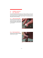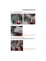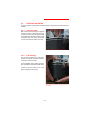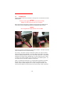
1
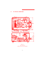
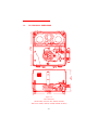
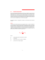
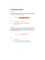
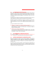
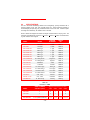
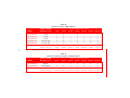
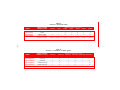
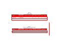
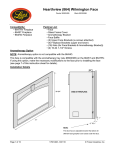
FORM 85-02
June 1999
Revision 6
AMETEK ®
PK II Pneumatic
Deadweight Tester
Operating Instructions
®
CALIBRATION INSTRUMENTS
-1-
TABLE OF CONTENTS
Page
1.0
INTRODUCTION AND PRODUCT OVERVIEW .....................................................
4
1.1
PRODUCT FEATURES ...........................................................................................
4
1.2
PK II PHYSICAL DIMENSIONS .............................................................................
5
2.0
CORRECTION FACTORS .......................................................................................
6
2.1
Corrections for Gravity ...........................................................................................
6
2.2
Corrections for Temperature ...................................................................................
7
2.3
Corrections for Air Head .........................................................................................
8
3.0
RECOMMENDED RECERTIFICATION PROCEDURE ...........................................
8
3.1
Frequency of Certification ......................................................................................
8
3.2
Materials Necessary for Recertification .................................................................
8
4.0
SPECIFICATIONS ...................................................................................................
9
5.0
ASSEMBLY AND SETUP .........................................................................................
13
5.1
Ball and Nozzle ........................................................................................................
13
5.1.1 Removing the Nozzle ..............................................................................................
13
5.1.2 Removing the Ball ...................................................................................................
13
5.1.3 Cleaning the Ball and Nozzle ...................................................................................
13
5.1.4 Cleanliness Check ..................................................................................................
13
5.2
Leveling the Tester ..................................................................................................
13
5.2.1 Fast Leveling ...........................................................................................................
13
5.2.2 Fine Leveling ...........................................................................................................
13
5.3
Connection ..............................................................................................................
14
6.0
OPERATING INSTRUCTIONS ................................................................................
15
7.0
MAINTENANCE .......................................................................................................
16
7.1
Output System ........................................................................................................
16
7.2
Input System ...........................................................................................................
17
-2-
TABLE OF CONTENTS
Page
8.0
TROUBLESHOOTING ............................................................................................
18
8.1
Correcting For Poor Weight Rotation ......................................................................
18
8.2
Output and Internal Leakage ...................................................................................
18
Output Connection Leakage .............................................................................
18
8.2.1
8.2.2
Internal Leakage Within the Tester ...................................................................
18
8.3
Replacing the Nozzle and O-Ring ............................................................................
18
9.0
PARTS LIST .............................................................................................................
19
TABLES
Page
2a
Pressure in PSIG .....................................................................................................
9
2b
Pressure in Inches of Water @ 20°C .....................................................................
10
2c
Pressue in Grams per Square Centimeter ..............................................................
10
2d
Pressure in Kilopascals ...........................................................................................
11
2e
Pressure in Centimeters of Water @ 20°C ............................................................
11
2f
Pressure in Bar ........................................................................................................
12
2g
Pressure in Millimeters of Mercury .........................................................................
12
PRODUCT WARRANTY
This instrument is warranted against defects in workmanship, material and design for one (1) year from
date of delivery to the extent that AMETEK will, at its sole option, repair or replace the instrument or any
part thereof which is defective, provided, however, that this warranty shall not apply to instruments
subjected to tampering or abuse, or exposed to highly corrosive conditions.
THIS WARRANTY IS IN LIEU OF ALL OTHER WARRANTIES WHETHER EXPRESS OR IMPLIED AND
AMETEK HEREBY DISCLAIMS ALL OTHER WARRANTIES, INCLUDING, WITHOUT LIMITATION, ANY
WARRANTY OF FITNESS FOR A PARTICULAR PURPOSE OR MERCHANTABILITY. AMETEK SHALL
NOT BE LIABLE FOR ANY INCIDENTAL OR CONSEQUENTIAL DAMAGES INCLUDING, BUT NOT
LIMITED TO, ANY ANTICIPATED OR LOST PROFITS.
This warranty is voidable if the purchaser fails to follow any and all instructions, warnings, and cautions
in the instrument’s Instruction Manual.
If a manufacturing defect is found, AMETEK will replace or repair the instrument or replace any defective
part thereof without charge; however, AMETEK’s obligation hereunder does not include the cost of
transportation which must be borne by the customer. AMETEK assumes no responsibility for damage in
transit, and any claims for such damage should be presented to the carrier by the purchaser.
-3-
1.0 INTRODUCTION AND PRODUCT OVERVIEW
The AMETEK® PK II Pneumatic Deadweight Tester is a primary standard that produces a
pressure by applying force (weight set) over area (the ceramic ball and nozzle). The PK II
tester is NIST traceable and accurate to +0.015% of indicated reading using stainless steel
weights calibrated to international standard gravity at 980.665cm/sec2. The unit is intended
for low pressure applications up to 30 PSIG (2 bar). The PK II tester may also be calibrated
to the user’s local gravity or to inches or centimeters of H2O at 20°C per ISA recommended
practices, or to reference water columns at 60°F per AGA standard practices.
The PK II tester is self-regulating with accuracy independent of the operator. The tester
utilizes a frictionless ceramic ball which floats on a layer of air within a stainless steel
cylinder.
The PK II tester features a sturdy cast-metal base with integral quick-leveling system for
field or laboratory use. The case also contains a tripod fixture allowing the unit to be tripod
mounted in the field.
1.1 PRODUCT FEATURES
The key features of the PK II Pneumatic Deadweight Tester are:
G
G
G
G
G
G
G
G
G
Accuracy up to +0.015% of indicated reading
Floating ball operation eliminates need to rotate weights during testing
Self regulating input air flow maintains ball and weights in a float position and compensates for variations in air supply pressure
Rugged ceramic measuring ball withstands harsh environments and field use
Monocontaminating fluid eliminates the need to clean instruments after calibration or
before use
Close cover operation eliminates wind effects in field calibrations
Multi-position ball valves for both the inlet and outlet connections ensures trouble-free
operation
Certificate of Accuracy and Traceability available with area, mass and intrinsic correction factors
Rugged aluminum housing offers long life. Top (Front) housing is reversible.
-4-
1.2
PK II PHYSICAL DIMENSIONS
8.875 in
225.4 mm
12.75 in
323.85 mm
6.125 in
155.56 mm
3.0 in
76.2 mm
Figure 1.1
PK II Dimensions
(Models 104, 254, 304 and Medical)
-5-
PK II PHYSICAL DIMENSIONS
8.0 in
203.2 mm
12.75 in
323.85 mm
1.2
12.875 in
327.03 mm
Figure 1.2
PK II Dimensions
(Models 20SS, 30SS, 654, 854, 2000GM, 2010GM
200N, 201N, 500CM, 1000CM, 1500CM, 2000CM, 2B, 2B01)
-6-
2.0
CORRECTION FACTORS
An error in pressure determinations may result from any uncertainty of the mass of the
loading weights and from the measurement of the effective area of the ball and nozzle.
Other sources of error, however, may not be easily recognized. Other sources of error
include the air buoyancy of the weights, gravity, thermal expansion and elastic deformation
of the ball and nozzle, and the air heads involved. All of these corrections, with the
exception of local gravity (except when specified), thermal expansion, and air heads have
been corrected for by AMETEK prior to the tester being shipped.
The following technique is suggested to compute the corrected tester output pressure
readings:
Gravity
Local gravity values differ depending upon geographic locations. Pressure is defined as
“force per unit area”, so that mass values must be converted to force values. To accomplish
this, the acceleration of gravity must be used. The acceleration of local gravity may be
determined by having a gravitational survey made of the local area with a gravimeter or by
contacting various governing bodies such as the National Oceanic and Atmospheric Administration, U.S. Department of Commerce. Once the local value of gravity is known, the
pressure may be corrected using the following formula:
PG =
G x P
N
GW
Where:
PG
= tester output pressure corrected only for gravity
G
= local gravity
GW
= gravity value for which the tester is calibrated
PN
= pressure value of weights applied
-7-
Temperature
If the coefficient of expansion of the ball and nozzle is positive, the effective area will
increase with increasing temperature resulting in a corresponding decrease in pressure.
Corrections can be made using the following formula:
PT =
PG
1 + 1.67 x 10⁻⁵ (T - 23°C)
Where:
PG
= tester output pressure corrected only for gravity
PT
= tester output pressure corrected for gravity and temperature
T
= ambient temperature (°C)
Air Head
When pressurized, a correction is required only when the gauge height or reference plane
of the unit being calibrated is either higher or lower than that of the pneumatic tester. The
reference plane of the tester is at the top of the nozzle. Heights above the reference plane
are negative, while heights below the reference plane are positive. Corrections can be
made using the following formula:
PA =
PT (1 + H x 2.84 x 10⁻⁶)
Where:
H
= air head (Inches)
PT
= tester output pressure corrected for gravity and temperature
P
= tester output pressure corrected for gravity, temperature and air head
A
-8-
3.0
CALIBRATION AND RECERTIFICATION
The accuracy of measurements can only be ensured through calibration against reference
standards of a known and well characterized measurement uncertainty; reference standards that are ultimately traceable through a national standards laboratory to the International Bureau of Weights and Measures (BIPM), to a natural physical constant, or to consensus standards.
All AMETEK pressure calibrations are traceable in the United States of America to reference
masters calibrated by the National Institute of Standards and Technology (NIST).
Measurement performance is affected by the frequency and severity of use, the environment, test conditions, and by other factors. AMETEK recommends calibration on a prescribed interval/frequency in order to ensure optimal measurement performance and reliability.
Two types of calibration services are offered:
G Calibration with a Certificate of Conformance/Certificate of Compliance
A statement of conformity which documents that the listed device(s) conforms to published specifications, or the terms of the order/contract. It can provide, in addition, a
statement of traceability to NIST.
G Calibration with a Calibration Report/Certificate
A report that outlines detailed information about the calibration process. This includes
actual calibration data, traceability information, test conditions, and other factors as may
be applicable to the type of device being calibrated.
3.1
RECOMMENDED CALIBRATION FREQUENCY
As a general rule, AMETEK pneumatic testers should be tested and recertified every 12
months. Testers used on a more frequent basis should be tested more frequently.
3.2
MATERIALS NECESSARY FOR RECERTIFICATION
Both the tester assembly and weight set should be returned to AMETEK in order to allow for
calibration of the tester as a “system”. Pressure is a derived parameter requiring determinations of both effective area and force (weight-mass). Instruments not sent to AMETEK as
a “system” can only be provided with certifications on the parameter calibrated, e.g. effective area or mass.
All materials should be securely packaged to prevent damage during transportation and
handling. Testers should be returned in their case. The ball/nozzle assembly should be
wrapped with adequate padding material and well secured to avoid shifting, movement and
to protect them from shock during transportation.
-9-
4.0
SPECIFICATIONS
The PK II Pneumatic Deadweight Testers are self-regulating, primary standards with a
pressure capacity of 104- 254-, 304- and 854-inches H2O. These instruments operate on
the deadweight principle using only fundamental units of force and area. Pressure equals
the weight force divided by the effective area of the ball.
All PK II Testers are shipped with tester and weight contained within a carrying case. The
instrument is available with accuracies of +0.015%, +0.025% or +0.05% of indicated reading with stainless steel weights.
RANGE
MINIMUM
INCREMENT
WEIGHT
SET
1-20 PSIG
1 PSIG
Table 2a
PK2-30SS
1-30 PSIG
1 PSIG
Table 2a
PK2-104WC-SS
4-100” H2O
1” H2O
Table 2b
PK2-254WC-SS
4-254” H2O
1” H2O
Table 2b
PK2-304WC-SS
4-304” H2O
1” H2O
Table 2b
PK2-654WC-SS
4-654” H2O
1” H2O
Table 2b
PK2-854WC-SS
4-854” H2O
1” H2O
Table 2b
PK2-2000GM-SS
25 - 2000 gm/cm2
25 gm/cm2
Table 2c
PK2-2010GM-SS
10 - 2000 gm/cm2
5 gm/cm2
Table 2c
Table 2d
MODEL
PK2-20SS
PK2-200N-SS
2-200 KPa
2 KPa
PK2-201N-SS
1 - 200 KPa
0.5 KPa
Table 2d
PK2-500CM-SS
10 - 500 cm H2O
10cm H2O
Table 2e
PK2-100CM-SS
10 - 1000 cm H2O
10 cm H2O
Table 2e
PK2-1500CM-SS
10-1500 cm H2O
10 cm H2O
Table 2e
PK2-2000CM-SS
10 - 2000 cm H2O
10 cm H2O
Table 2e
PK2-2B-SS
0.02 - 2 bar
0.02 bar
Table 2f
PK2-SB .01-SS
0.01 - 2 bar
0.005 bar
Table 2f
PK2-MEDICAL
10 - 325 mm Hg
5 mm Hg
Table 2g
Table 2a
Pressure in PSIG
WEIGHT CARRIER
AND BALL (PSIG)
1 PSI
2 PSI
PK2-20SS
1
2
1
3
PK2-30SS
1
2
1
5
K-2000 (PK2-20, PK2-30)
K-2011
MODEL
Part Number
- 10 -
Weights Furnished per Pressure Increment
3 PSI
5 PSI
K-2012 K-2013 K-2013-5
Table 2b
Pressure in Inches of Water @ 20°C
MODEL
PK2-104WC-SS
WEIGHT CARRIER
AND BALL (in H2O)
1” H2O
2” H2O
4” H2O
1
4
Weights Furnished per Pressure Increment
5” H2O
10” H2O
20” H2O
50” H2O
100” H2O
11
9
- 11 -
PK2-254WC-SS
4” H2O
1
2
1
2
1
2
PK2-304WC-SS
4” H2O
1
2
1
2
1
1
2
PK2-654WC-SS
4” and 10” H2O
1
2
1
2
1
2
5
PK2-854WC-SS
4” and 10” H2O
1
2
1
2
1
2
7
Part Number
K-1279 (4” H2O)
K-1277
K-1278
K-2047-1
K-1294
K-2046-16
K-2030
K-2031
K-1265-1 (10” H2O)
NOTE:
1
1
Weight insert accepts optional 100” H2O weight.
Table 2c
Pressure in Grams per Square Centimeter (g/cm 2 )
MODEL
WEIGHT CARRIER
AND BALL (g/cm2)
PK2-2000GM-SS
25g/cm2
PK2-2010GM-SS
25 and 10g/cm2
Part Number
Weights Furnished per Pressure Increment
5g/cm2
10g/cm2
1
2
25g/cm2
50g/cm2
100g/cm2 200g/cm2 500g/cm2
1
1
2
1
3
1
1
2
1
3
K-1279-4 (10g/cm2)
K-1265-13 (25g/cm2)
K-2047-33 K-2047-32 K-2046-30 K-2046-19 K-2030-5 K-2039-14 K-2039-11
Table 2d
Pressure in Kilopascals (KPa)
MODEL
WEIGHT CARRIER
AND BALL (KPa)
PK2-200N-SS
2 KPa
PK2-201N-SS
2 KPa & 1 KPa
Part Number
Weights Furnished per Pressure Increment
0.5 KPa
1 KPa
1
1
2 KPa
4 KPa
10 KPa
20 KPa
50 KPa
2
1
2
1
3
2
1
2
1
3
K-1279-2 (1KPa)
K-1265-12 (2 KPa)
K-2047-17 K-2047-18 K-1294-2 K-2046-29 K-2030-1
K-2031-3 K-2039-12
- 12 Table 2e
Pressure in Centimeters of Water @ 20°C
MODEL
PK2-500CM-SS
WEIGHT CARRIER
AND BALL (cm H2O)
10cm H2O
10 cm H2O
1
Weights Furnished per Pressure Increment
20cm H2O
2
50cm H2O
1
100cm H2O 200cm H2O 500cm H2O
2
1
PK2-1000CM-SS
10 cm H2O
1
2
1
2
1
1
PK2-1500CM-SS
10 and 25 cm H2O
1
2
1
2
1
2
PK2-2000CM-SS
10 and 25 cm H2O
Part Number
1
2
1
2
1
3
K-2047-24
K-2045-10
K-2046-24
K-2031-18
K-2031-19
K-2031-20
Table 2f
Pressure in Bar
MODEL
WEIGHT CARRIER
AND BALL (Bar)
PK2-2B-SS
0.02 Bar
PK2-.01-SS
0.01 and 0.02 Bar
Part Number
Weights Furnished per Pressure Increment
0.005 bar
0.01 Bar
0.02 Bar
0.04 Bar
0.1 Bar
2
1
2
1
3
1
1
2
1
2
1
3
K-2047-17 K-2047-18 K-1294-2 K-2046-29 K-2030-1
0.2 Bar
0.5 Bar
K-2031-3 K-2039-12
- 13 Table 2g
Pressure in Millimeters of Mercury (Hg)
MODEL
WEIGHT CARRIER
AND BALL (mm Hg)
PK2-MED
10 mm Hg
Part Number
Weights Furnished per Pressure Increment
5 mm Hg
10 mm Hg
20 mm Hg
50 mm Hg
100 mm Hg
1
2
2
1
2
K-2047-23
K-2047-22
K-2046-25
K-2046-21
K-2012-1
5.0
ASSEMBLY AND SETUP
5.1
BALL AND NOZZLE
You should routinely check the ceramic ball and the nozzle for cleanliness. Never scrape
the nozzle or its associated parts with a hard object or anything that is abrasive or that may
remove material from the parts. AMETEK recommends that the ceramic ball and nozzle be
kept in place at all times, except when cleaning is required. This will prevent dirt from
entering the ball and nozzle assembly.
5.1.1
Removing Ceramic Ball
Cup one hand over the top (beveled end) of
the nozzle and push from the bottom of the
nozzle to remove the ball. If the ball tends to
stick when being removed, DO NOT FORCE
IT. Forcing the ball may cause serious damage to the nozzle.
Carefully, lift the ceramic ball from the nozzle assembly and
store in a secure location.
5.1.2
Removing the Nozzle
Carefully remove the nozzle by pulling the
nozzle upward while twisting to overcome
the friction of the O-ring seal.
Grasp the nozzle firmly and pull upward with a slight twisting
motion.
- 14 -
5.1.3
Cleaning Ball and Nozzle
AMETEK recommends cleaning the ceramic ball and nozzle with a residue-free solvent.
Using a cottom swab or soft cloth with a solvent such as alcohol,
wipe the inside of the nozzle.
Dampen a clean cloth with alcohol or other residue-resistant
solvent, and clean the ceramic ball by rotating it within the cloth.
5.1.4
Ball & Nozzle Cleanliness Check
The ball should pass smoothly through the nozzle bore without any restriction or friction. If
resistance is felt, reclean the ceramic ball and nozzle and repeat cleanliness check.
After the ball and nozzle have been cleaned, slide the ball through
the nozzle. The ball should pass through the nozzle with no
resistance.
- 15 -
5.1.4
Ball & Nozzle Reassembly
After ensuring that both the ceramic ball and nozzle are clean, reassembly by first placing
the nozzle back into proper position and alignment. Always make sure that the serial number
on the nozzle is directly above the serial number of the nozzle body.
CORRECT ALIGNMENT- The serial number for the nozzle
(top) aligns with the serial number of the nozzle body (bottom).
INCORRECT ALIGNMENT- The serial numbers DO NOT align
and may lead to inaccurate readings.
- 16 -
5.2
LEVELING THE TESTER
For proper operation, the PK II tester should be placed on a support that is solid and free from
vibration.
5.2.1
Coarse Leveling
Both coarse and fine leveling are supported
by the PK II tester. Coarse leveling to raise
the tester is achieved by pushing the knurled
rod (located inside the case on either side of
the weight insert) and rotating the knurled
nut until it contacts the bottom of the case.
For coarse adjustment, use the knurled rod located on the top.
5.2.2
Fine Leveling
Fine leveling is obtained by rotating the
knurled rod clockwise to raise and counterclockwise to lower the tester.
A third adjustable foot is located under the
PK II case between the inlet and outlet valves.
A bull’s-eye level is located on the cover
plate for sighting level accuracy.
For fine adjustment, hold the bottom foot and rotate the knurled
knob at the top.
- 17 -
5.3
CONNECTION
Connect a supply of clean, dry and oil-free air or nitrogen to the connection below the valve
marked “INLET”.
CAUTION
The use of other gases will result in an incorrect reading.
Always use clean, dry and oil-free air or nitrogen.
When using the tester thru full range, regulate the supply pressure at 30 PSIG minimum,
however take care NOT TO REGULATE THE SUPPLY PRESSURE OVER 100 PSIG.
WARNING
Do not regulate the supply pressure over 100 PSIG.
Connect clean, dry and oil-free air or nitrogen to the INLET valve.
Connect instrument to be tested to the OUTLET valve.
Connect the instrument to be tested to the valve marked “OUTLET”. The tester’s input and
output connections are 1/4-inch male tube fittings.
The accuracy of the tester is seriously undermined by leaks in the output connections
and/or the instrument being calibrated. To check for leaks, load the tester so as to apply
a pressure indicating instrument and then turn off the tester output valve. If the pressure
indicated by the instrument being calibrated holds, it is safe to assume their are no leaks.
If, however, the pressure decreases, there is likely a leak in the calibration system. You
must locate and fix the leak before calibration can take place.
Under no circumstances should mercury or corrosive fluids be permitted into the tester.
When the tester is used in connection with an instrument or pressure system that
contains a liquid, a suitable safeguard such as a trap or float-type manometer check
valve should be installed in the tester output line to prevent fouling of tester components.
- 18 -
6.0
OPERATING INSTRUCTIONS
The following steps are provided to guide the user through a typical calibration using the PK
II tester.
Step 1
Slip the weight carrier over the ceramic ball.
Slide the weight carrier over the ball and nozzle assembly.
Step 2
Admit the supply pressure to the tester by
turning on the valve marked “INLET”.
WARNING
NEVER connect the PK II tester to a
high pressure source.
Applying high pressure may result in
personal injury and
damage to the tester.
NEVER apply a pressure greater than
100 PSIG.
Open the INLET valve and supply pressure to the tester.
Step 3
Add weights as required. Exercise
caution when handling the weights.
Handle only one weight at a time to avoid
damaging the weights.
Add the required weights by sliding the weights over the carrier.
Apply the heavier weights first. Always store the weights in the
compartment provided in the PK II tester case.
- 19 -
6.0
OPERATING INSTRUCTIONS (Cont’d.)
Step 4
Weights may be given a slow rotary motion
to ensure that the weights rotate freely
without abrupt stopping. (See Section 6.1
to correct for poor weight rotation).
Note: It is not necessary to excessively
spin the weights of the pneumatic
deadweight tester to overcome friction.
Excessive rotation may affect accuracy.
WARNING
Do NOT spin the weights unless the
ceramic ball is floating.
Slowly rotate the weights to ensure that there are no restrictions
and that the weights float freely.
Step 5
Open the tester “OUTLET” valve and
calibrate the instrument. Once calibration
is complete, the downstream pressure
may be vented by turning the outlet valve
to the “VENT” position.
Open the OUTLET valve to calibrate the instrument. Once the
calibration is completed, you may vent the pressure by rotating
the OUTLET knob to the VENT position.
CAUTION
The ceramic ball, weight carrier and
weights comprise a “system” for
your PK II calibrator and should be
used together to ensure a correct
calibration. Accuracy will be affected
if the ceramic ball, weight carrier and
weights are interchanged.
- 20 -
7.0
MAINTENANCE
7.1
OUTPUT SYSTEM
The PK II tester features an output tank that may be cleaned. If any contamination is evident
in the output system, it may be easily removed using the following procedure:
Step 1
Remove the weights and weight carrier from
the tester leaving the ceramic ball in place.
Step 2
Connect an air supply to the tester.
Step 3
Disconnect the output line.
- 21 -
Step 4
Fully open both the INLET and OUTLET
valves.
Step 5
While holding the ceramic ball (to ensure that
the ball does not fall out), tilt the tester so
that the output connection is pointing downward.
Step 6
Pressure the ball into its socket to provide an
output pressure sufficient to purge the system.
Step 7
After completing Steps 1 - 6, disconnect the
air supply from the INLET and connect the air
supply to the OUTLET. DO NOT APPLY PRESSURE AT THIS TIME.
Step 8
Using a screw driver, remove the ceramic
ball and restriction tube. The restriction tube
is located under the ceramic ball.
- 22 -
Step 9
Remove the nozzle.
Step 10
Place a cloth or absorbent material over the
nozzle body.
Step 11
Apply 15 to 30 PSI to the OUTLET for a few
seconds or until the material on the nozzle
body is clean and dry when removed. Mild
solvents may be applied to the outlet fitting
and flushed out when applying pressure. If
a solvent is used, it should not leave any film
or residue once dried.
Step 12
Clean the output restriction using a 1/32” drill
or piece of 22 gauge wire to clean out any
obstructions.
Step 13
Clean the ceramic ball, nozzle and body thoroughly.
- 23 -
7.2
INPUT SYSTEM
The PK II tester features an input filter located within the 1/4” male tube fitting on the outside
of the PK II tester case. As this filter becomes dirty, the tester may react by not supporting
the weights. To correct, remove the filter and examine the NPT opening for any contamination.
CLEANING THE INPUT FILTER
Remove the input filter fitting and clean it by
backflushing from the downstream end with
clean compressed air. If an ultrasonic
cleaner is available, AMETEK recommends
that the filter fitting be cleaned using the ultrasonic cleaner for 10 to 15 minutes in a
residue-free solvent.
CAUTION
Do NOT attempt to remove the filter
element from the fitting.
Filters should be replaced periodically.
- 24 -
8.0
TROUBLESHOOTING
The following represent common troubleshooting tips for the PK II tester.
8.1
CORRECTING FOR POOR WEIGHT ROTATION
If weights do not rotate freely as described in Section 6.0, Step 4, perform the following:
Step 1
Check the cleanliness of the ceramic ball and nozzle.
Step 2
Make sure the tester is level by checking the bull’s eye.
Step 3
Isolate tester from environmental vibrations or relocate tester.
Step 4
Check for adequate air supply.
8.2
OUTPUT AND INTERNAL LEAKAGE
The accuracy of the tester is seriously undermined by leaks in the output connections and/
or instrument being calibrated. The following procedures are recommended to isolate and
correct for leakage.
8.2.1
Output Connection Leaks
Load the tester so as to apply a pressure to
the instrument being calibrated. Close (turn
OFF) the OUTLET valve. If the pressure indicated by the instrument being calibrated remains constant (holds at the indicated pressure), it is safe to assume there are no leaks
in the output system (between the tester and
the instrument).
- 25 -
8.2.2
Internal Leaks
You can perform a check for internal leaks with the input pressure applied and with the
cover plate off.
Step 1
Place full range of weights onto tester.
Step 2
Turn OFF (Close) the OUTPUT valve.
Step 3
Apply liquid leak detector to all internal fittings from the input connection to the output
valve.
Step 4
Check for leaks by the presence of bubbles
on joints.
Step 5
If a leak is found, the PK II Tester must be
returned to AMETEK for repair.
WARNING
Leak checks should be done in the
order described above,
otherwise the source of the leak may
not be accurately identified.
CAUTION
DO NOT ATTEMPT TO REPAIR
INTERNAL LEAKS.
Return the PK II tester to AMETEK for
internal leak repairs.
Failure to do so may void product
warranty.
8.3
REPLACING THE NOZZLE AND O-RING
Remove the ball and nozzle and the nozzle O-ring (10-90013). The replacement O-ring
should be wiped clean with a lint-free cloth and placed within the groove in the nozzle
body. DO NOT LUBRICATE THE O-RING WITH ANY FORM OF OIL OR GREASE.
Clean the ball and nozzle as described in Section 5.1.3.- Cleaning the Ball and Nozzle,
and reassemble.
- 26 -
9.0
PARTS LIST
PART
NUMBER
K-1035
K-1048
K-1050/ETCH
10-90013
K-1051
K-1182
K-1193
K-1209
K-1212
K-1216
K-1217
K-1223
K-1224
K-1246
K-1273
K-1297
K-1303
K-1831
K-1832
K-1833
K-1834
K-1835
K-1836
K-1839
K-1840
K-1850
K-1868/ASSY
K-1896/ASSY
K-1880
K-1882
03-90020
04-90047
06-90040
12-90040
11-90062
13-90003
13-90022
DESCRIPTION
Nameplate
Nozzle Body Restriction Screw
Nozzle
Nozzle O-Ring
Ceramic Ball
Spring
Retainer
Regulator Nozzle Block
Disc, Clip and Diaphragm Assembly
Regulator Ratio Disc Diaphragm (Stem Side)
Regulator Ratio Disc Diaphragm (Flat)
Gasket
Regulator Assembly Screw
Bulls-Eye Level
Label (Inlet, Outlet, Caution)
Capacity Tank Assembly
Nozzle Body Restriction Assembly
Tripod Mounting Plate
Level Adjust Stud
Level Retainer Stud
Leveling Foot
Leveling Foot Assembly
Aluminum Adjusting Nut (3/8”-24)
Nut (5/8-18 x 1/8”)
Regulator Assembly
Filter Assembly
Internal Cover Assembly (Small Case)
Internal Cover Assembly (Large Case)
Regulator Bracket
Weight Retainer Block
Screw (2-56 x 5/16)
Nut (7/16-20)
Brass Washer (0.74” OD)
1/8” NPT x 1/8” Tube Straight Connector
Bulkhead Fitting
Outlet Valve
Inlet Valve
- 27 -
®
CALIBRATION INSTRUMENTS
AMETEK Test and Calibration
Instruments
8600 Somerset Drive
Largo, Florida 33773
Tel
+1 (727) 536-7831
Tel
+1 (800) 527-9999
Fax
+1 (727) 539-6882
AMETEK Precision
Instruments Europe GmbH
Rudolf-Diesel-Strasse 16
D-40670, Meerbusch
Germany
Tel
+49 2159 9136 0
Fax
+49 2159 9136 39
AMETEK Singapore Pvt. Ltd.
10 Ang Mo Kio Street 65
#05-12 TECHPOINT
Singapore
569059
Tel
+65 484 2388
Fax
+65 481 6588
AMETEK Denmark A/S
Gydevang 32-34
DK-3450 Allerod
Denmark
Tel
Fax
+45 4816 8000
+45 4816 8080
Internet Addresses:
www.ametek.com
Information within this document is subject to change
without notice.
ISO 9001
Manufacturer
AMETEK is a registered trademark of AMETEK, Inc.
Pub No. FORM 85-02 (Rev 6)
Issued 06/99
Copyright 1999, by AMETEK, Inc.
- 28 -
Printed in U.S.A.