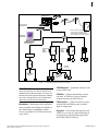
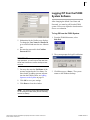
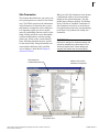
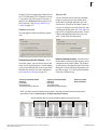
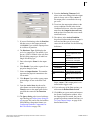
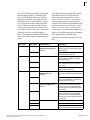
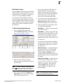
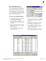
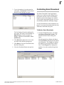
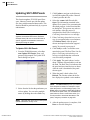
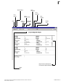
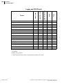
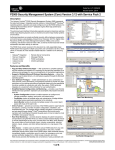
1
P2000 Security Management System software user manual version 3.12 SP2 24-10685-157 Revision D March, 2014 Copyright 2014 Johnson Controls, Inc. All Rights Reserved No part of this document may be reproduced without the prior permission of Johnson Controls, Inc. If this document is translated from the original English version by Johnson Controls, Inc., all reasonable endeavors will be used to ensure the accuracy of translation. Johnson Controls, Inc. shall not be liable for any translation errors contained herein or for incidental or consequential damages in connection with the furnishing or use of this translated material. Due to continuous development of our products, the information in this document is subject to change without notice. Johnson Controls, Inc. shall not be liable for errors contained herein or for incidental or consequential damages in connection with furnishing or use of this material. Contents of this publication may be preliminary and/or may be changed at any time without any obligation to notify anyone of such revision or change, and shall not be regarded as a warranty. Other Manufacturer’s Documentation Johnson Controls does not duplicate documentation of other equipment manufacturers. When necessary, Johnson Controls provides documentation that supplements that of other manufacturers. When unpacking your equipment, keep all original manufacturer documentation for future reference. Technical Support Johnson Controls authorized dealer representatives can call the Field Support Center at (800) 524-1330 or (414) 524-5000 and use options 6, 1, 7. System users that need information on maintenance contracts or on-site field support can call a local Johnson Controls sales or service office. Acknowledgment Metasys® and Johnson Controls® are trademarks of Johnson Controls, Inc. All other company and product names are trademarks or registered trademarks of their respective owners. Declaration of Conformity This product complies with the requirements of the EMC Directive 2004/108/EC and the Low Voltage Directive 2006/95/EEC. This equipment must not be modified for any reason and it must be installed as stated in the Manufacturer’s instruction. If this shipment (or any part thereof) is supplied as second-hand equipment, equipment for sale outside the European Economic Area or as spare parts for either a single unit or system, it is not covered by the Directives. i Table of Contents Chapter 1: Introduction ..................................................................................................1 Getting Started ........................................................................................................................1 Chapter Summaries ................................................................................................................1 Manual Conventions................................................................................................................2 Basic System Components .....................................................................................................2 Main Menu...............................................................................................................................5 Registration Parameters..........................................................................................................6 System Overview ....................................................................................................................6 Basic Configuration...........................................................................................................6 Network Communication.............................................................................................6 Loop Communication..................................................................................................7 Communication Modes .....................................................................................................7 Types of Communication ............................................................................................8 Access Requests ..............................................................................................................8 Time and Time Zones.................................................................................................8 Valid or Invalid Badges ...............................................................................................8 Badge Privileges.........................................................................................................8 Controlling Special Access................................................................................................9 Overriding Basic Access.............................................................................................9 Granting Badge Privileges ..........................................................................................9 Alarms...............................................................................................................................9 External Device Alarms ..............................................................................................9 Door Alarms................................................................................................................9 Software-Only Alarms.................................................................................................9 P2000 Host Alarms...................................................................................................10 Remote Alarms .........................................................................................................10 Non-alarm Input Points ...................................................................................................10 Output Relays .................................................................................................................10 Input and/Output Linking...........................................................................................10 Activating Outputs by Events....................................................................................10 Activating Outputs Manually .....................................................................................10 Events .............................................................................................................................10 Database Partitioning......................................................................................................11 Logging On to the P2000 System Software ..........................................................................11 Changing the Default Login Values.......................................................................................12 Logging Off from the P2000 System Software ......................................................................13 Navigating through the P2000 System..................................................................................14 Mouse Conventions ........................................................................................................14 This document contains confidential and proprietary information of Johnson Controls, Inc. © 2014 Johnson Controls, Inc. 24-10685-157 Rev. D ii TABLE OF CONTENTS Instruction Conventions.........................................................................................................14 Menu Shortcuts...............................................................................................................15 Verification Passwords....................................................................................................15 Context Sensitive Help....................................................................................................15 Online Help .....................................................................................................................16 P2000 Tutorial.................................................................................................................16 Viewing the Toolbar ........................................................................................................16 Chapter 2: Configuring the System .....................................................................17 System Configuration Overview ............................................................................................17 Using the System Configuration Window........................................................................17 Set Up Workstations and Operators......................................................................................19 Workstations ...................................................................................................................19 Workstation Field Definitions ....................................................................................20 Adding Operators to the System.....................................................................................21 Creating Permission Groups.....................................................................................21 Assigning Operators .................................................................................................22 P2000 Directory Services Password Validation........................................................27 Changing the User Password...................................................................................28 Setting Up User Accounts...............................................................................................28 Adding a Login Name and Password for the P2000 System into the Operating System .....................................................................................................28 Configure System Components ............................................................................................32 Registration Parameters .................................................................................................32 Site Parameters ..............................................................................................................33 Site Parameters Field Definitions .............................................................................34 Local Site ........................................................................................................................47 Local Configuration .........................................................................................................48 Time Zones .....................................................................................................................49 Configuring Time Blocks...........................................................................................49 Holiday Types ...........................................................................................................51 Holiday ............................................................................................................................51 Using the Holiday Calendar ......................................................................................52 Assigning Holiday Types ..........................................................................................52 Configure Hardware Components.........................................................................................53 Hardware Configuration Sequence.................................................................................53 Create Panels .................................................................................................................53 Panel Naming Conventions ......................................................................................53 Loop Configuration ...................................................................................................54 Soft Input Points .......................................................................................................56 Edit Panel Field Definitions.......................................................................................56 Configure Panel Components.........................................................................................65 Configure Panel Time Zones ....................................................................................66 Configure Panel Holidays .........................................................................................67 Enable Codes (EC) Definition...................................................................................68 24-10685-157 Rev. D This document contains confidential and proprietary information of Johnson Controls, Inc. © 2014 Johnson Controls, Inc. iii Configure Air Crew PIN Numbers.............................................................................68 Configure Panel Card Formats .................................................................................69 Configure Additional Panel Components..................................................................70 Create and Configure Terminals.....................................................................................70 Set up Terminals for each Panel ..............................................................................70 Edit Terminal Field Definitions ..................................................................................71 Use the Add Hardware Module.................................................................................83 Create Terminal Groups ...........................................................................................85 Configure PIN Codes ......................................................................................................86 PIN Only ...................................................................................................................86 PIN + Card ID ...........................................................................................................87 PIN............................................................................................................................87 Four-Digit PINs .........................................................................................................87 PIN Duress ...............................................................................................................87 PIN Retry Alarm........................................................................................................88 Create Input and Output Points and Groups...................................................................88 Create Output Points and Groups ............................................................................88 Create Input Points and Groups ...............................................................................90 Create Input Points ...................................................................................................90 Input Point Field Definitions ......................................................................................90 Configuring Reader Terminal Hardwired Input Points ..............................................95 Using Reader Terminal Door Contact Input Points...................................................96 Using the Terminal Down Input Point .......................................................................96 Create Input Groups .................................................................................................97 Creating Instruction Text...........................................................................................97 Create Panel Card Events ..............................................................................................99 Panel Card Event Field Definitions ...........................................................................99 Configure Soft Alarms...................................................................................................101 Soft Alarms Field Definitions...................................................................................101 Configure P900 Panels and Components.....................................................................103 P900 to P2000 Terminology Cross Reference .......................................................103 Import P900 Sequence Files ..................................................................................103 Configure P900 System Parameters ......................................................................104 Configure P900 Panels...........................................................................................105 Configure P900 Terminals ......................................................................................107 P900 Terminal Field Definitions..............................................................................107 Configure P900 Input/Output Points .......................................................................111 P900 Input Field Definitions....................................................................................112 P900 Soft Alarms....................................................................................................114 Configuring CLIC Components...............................................................................114 P900 Counters........................................................................................................114 P900 Flags..............................................................................................................115 P900 Trigger Events ...............................................................................................116 P900 Trigger Event Field Definitions ......................................................................116 P900 Trigger Links..................................................................................................119 Configure OSI Panels and Components.......................................................................120 This document contains confidential and proprietary information of Johnson Controls, Inc. © 2014 Johnson Controls, Inc. 24-10685-157 Rev. D iv TABLE OF CONTENTS Unsupported OSI Features.....................................................................................120 Unsupported P2000 Features.................................................................................120 System Architecture................................................................................................120 Hardware Detection ................................................................................................121 Badge Access Rights..............................................................................................122 Configuration Sequence .........................................................................................122 Configure OSI Facility Parameters .........................................................................122 OSI Facility Field Definitions...................................................................................123 Adding New Portals ................................................................................................127 Configure OSI Panels .............................................................................................128 Configure OSI Terminals ........................................................................................129 OSI Terminal Field Definitions ................................................................................130 Viewing OSI Wireless Devices Status ....................................................................132 Configure S321-IP Panels and Components ................................................................133 S321-IP Naming Conventions ................................................................................133 Configure S321-IP Panels ......................................................................................133 S321-IP Panel Field Definitions ..............................................................................134 Configure S321-IP Terminals .................................................................................137 S321-IP Terminal Field Definitions .........................................................................137 Configure S321-IP Input Points ..............................................................................140 S321-IP Input Point Field Definitions ......................................................................142 Configure S321-IP Output Points ...........................................................................144 Configure Isonas Panels and Components ..................................................................146 Configure Isonas Panels.........................................................................................146 Configure Isonas Terminals....................................................................................147 Isonas Terminal Field Definitions............................................................................148 Configure Isonas Input Points.................................................................................150 Configure Isonas Output Points..............................................................................151 Configure HID Panels and Components.......................................................................152 Hardware Requirements.........................................................................................152 HID Panel Naming Conventions .............................................................................153 Configure HID Facility Parameters .........................................................................153 Configure HID Panels .............................................................................................154 HID Panel Field Definitions.....................................................................................154 Configure HID Terminals ........................................................................................156 HID Terminal Field Definitions ................................................................................157 Configure HID Input Points .....................................................................................160 HID Input Point Field Definitions.............................................................................161 Configure HID Output Points ..................................................................................162 Troubleshooting Misconfigured HID Readers.........................................................163 Configure Assa Abloy® IP Door Locks and Components.............................................164 Hardware Requirements.........................................................................................165 Assa Abloy Component Naming Conventions........................................................165 Configure Assa Abloy Facility Parameters .............................................................166 Using the Card ID feature with Assa Abloy Locks ..................................................168 Add a Door Service Router (DSR)..........................................................................169 24-10685-157 Rev. D This document contains confidential and proprietary information of Johnson Controls, Inc. © 2014 Johnson Controls, Inc. v Edit Assa Abloy Panels...........................................................................................171 Assa Abloy Panel Time Zones................................................................................173 Assa Abloy Holiday Definition.................................................................................174 Configure Assa Abloy Terminals ............................................................................174 Assa Abloy Terminal Field Definitions ....................................................................175 Configure Assa Abloy Soft Input Points..................................................................176 Assa Abloy Status Information................................................................................177 Real Time Functions...............................................................................................178 Lockout Mode with Assa Abloy Locks ....................................................................178 File Maintenance on the DSR Server .....................................................................178 Configure Mercury Panels and Components ................................................................179 Configure Mercury Facility Parameters ..................................................................179 Mercury Facility Field Definitions ............................................................................179 Configure Mercury Panels ......................................................................................183 Mercury Panel Field Definitions ..............................................................................184 Configure Mercury Terminals .................................................................................187 Mercury Terminal Field Definitions .........................................................................189 Configure Mercury Inputs .......................................................................................196 Mercury Input Field Definitions ...............................................................................198 Configure Mercury Outputs.....................................................................................200 Configure Mercury Procedures and Triggers..........................................................202 Configuring Procedures ..........................................................................................202 Configuring Triggers ...............................................................................................204 Configure Mercury Elevators ..................................................................................206 Best Practices.........................................................................................................210 P2000 Badge Format....................................................................................................212 Configure Elevators and Cabinets.......................................................................................215 Elevator Access Control................................................................................................215 General Overview ...................................................................................................215 Basic Definitions .....................................................................................................216 Low Level Interface.................................................................................................216 KONE HLI/KONE ELINK High Level Interface .......................................................217 KONE IP High Level Interface ................................................................................217 Otis EMS - Security / BMS Protocol High Level Interface ......................................217 Otis Compass High Level Interface ........................................................................218 Defining Floor Names .............................................................................................220 Defining Floor Masks ..............................................................................................220 Configuring Elevators .............................................................................................221 Elevator Configuration Field Definitions..................................................................221 Configuring Floors ..................................................................................................225 Configuring Otis Unsecured Elevators....................................................................225 Configuring KONE IP Elevators..............................................................................226 Defining Floor Groups.............................................................................................231 Creating Access Groups for Elevator Floors ..........................................................231 Cabinet Access Control.................................................................................................231 Defining Door Names .............................................................................................232 This document contains confidential and proprietary information of Johnson Controls, Inc. © 2014 Johnson Controls, Inc. 24-10685-157 Rev. D vi TABLE OF CONTENTS Defining Door Masks ..............................................................................................233 Configuring Cabinets ..............................................................................................233 Cabinet Configuration Field Definitions ..................................................................233 Configuring Doors...................................................................................................235 Defining Door Groups .............................................................................................235 Creating Access Groups for Cabinet Doors............................................................236 Configure Message Filtering and Message Routing ...........................................................236 Operators and Messages..............................................................................................236 Basic Principles and Definitions....................................................................................236 Sequence of Steps........................................................................................................237 Message Filtering..........................................................................................................237 Create Message Filter Groups................................................................................244 Message Routing ..........................................................................................................245 Configuring P2000 Remote Servers .......................................................................245 P2000 Remote Server Field Definitions..................................................................245 Set up Access Groups and Cardholders .............................................................................247 Create Access Groups..................................................................................................247 Cardholder Options.......................................................................................................249 Define Companies and Departments......................................................................249 Create Access Templates.......................................................................................251 Access Template Edit Field Definitions ..................................................................251 Create Badge Formats ...........................................................................................252 Create Badge Purposes .........................................................................................253 Create Badge Reasons ..........................................................................................253 Create Required Cardholder Fields ........................................................................254 Create User Defined Fields ....................................................................................254 Define Automatic Employee IDs .............................................................................256 Entering Cardholders..............................................................................................257 Chapter 3: Operating the System .......................................................................259 Providing Access to Cardholders and Visitors ....................................................................259 Entering Cardholder Information...................................................................................260 Viewing Cardholder Information .............................................................................260 Cardholder Field Definitions ...................................................................................261 Adding a Cardholder Image....................................................................................264 Adding a Cardholder Journal ..................................................................................264 User Defined Fields ................................................................................................265 Entering Badge Information ..........................................................................................267 Badge Field Definitions...........................................................................................268 Viewing Badge Data ...............................................................................................274 Bulk Badge Change................................................................................................275 Entering Visitor Information...........................................................................................276 Add Visitor Field Definitions....................................................................................277 Auto Badge Management .............................................................................................279 Badge Resync...............................................................................................................280 24-10685-157 Rev. D This document contains confidential and proprietary information of Johnson Controls, Inc. © 2014 Johnson Controls, Inc. vii Image Recall .................................................................................................................282 Image Recall Filters ................................................................................................282 Image Recall FS (Full Screen)......................................................................................283 To Activate Image Recall FS: .................................................................................283 Monitoring Alarms ...............................................................................................................285 Alarm Configuration ......................................................................................................285 Alarm Category.......................................................................................................285 Alarm Handling..............................................................................................................286 Monitoring Remote Alarms............................................................................................287 Alarm Monitor Definitions........................................................................................288 Configuring Alarm Colors ..............................................................................................292 Creating Predefined Alarm Response Text...................................................................294 Monitoring Alarms Using the SIA Interface ...................................................................294 Message Forwarding.....................................................................................................296 Fire Alarm Control.........................................................................................................297 Basic Definitions .....................................................................................................297 Basic Fire Alarm Components ................................................................................298 Fire Alarm Server Configuration .............................................................................298 Fire Alarm Configuration.........................................................................................299 Fire Alarm Management .........................................................................................300 Controlling Fire Alarm Components........................................................................300 Viewing Fire Transactions Using the Real Time List ..............................................302 Monitoring Fire Components Using the Real Time Map.........................................302 Viewing and Controlling Fire Components Using the System Status Window .......302 Fire Component Events ..........................................................................................302 Operator Controls................................................................................................................303 Controlling Doors ..........................................................................................................303 Controlling Outputs .......................................................................................................304 Controlling Panel Relays...............................................................................................305 P900 CLIC Controls ......................................................................................................305 To Manually Control a P900 Counter: ....................................................................305 To Manually Control a P900 Flag: ..........................................................................306 To Manually Control a P900 Trigger Event:............................................................306 Security Threat Level Control........................................................................................307 Defining Security Levels .........................................................................................307 Applying Security Level ..........................................................................................308 Input Point Suppression................................................................................................309 Controlling Areas and Muster Zones...................................................................................310 Area Control..................................................................................................................310 Configuring the Area...............................................................................................310 Controlling the Area ................................................................................................313 Defining Area Filters ...............................................................................................315 Displaying Area Details...........................................................................................315 Area Details Field Definitions..................................................................................316 Area Layout ............................................................................................................317 Area Reports...........................................................................................................318 This document contains confidential and proprietary information of Johnson Controls, Inc. © 2014 Johnson Controls, Inc. 24-10685-157 Rev. D viii TABLE OF CONTENTS Mustering ......................................................................................................................319 Basic Definitions .....................................................................................................319 Sequence of Steps .................................................................................................320 Define Risk Areas and Muster Zones .....................................................................320 Muster Zone Definition Fields .................................................................................321 Defining Zone Terminals.........................................................................................324 Defining Muster Terminals......................................................................................324 Defining Sequester Terminals ................................................................................325 Mustering Events ....................................................................................................326 Controlling Muster Zones........................................................................................327 Muster Zone Status and Control Field Definitions ..................................................327 Viewing and Printing Muster Transactions in Real Time ........................................330 Muster Reports .......................................................................................................330 Intrusion Detection ..............................................................................................................331 Basic Definitions ...........................................................................................................332 Sequence of Steps........................................................................................................333 Intrusion Configuration..................................................................................................333 OPC Aritech Intrusion Interface ..............................................................................333 Bosch Intrusion Interface........................................................................................334 Mercury Intrusion Interface.....................................................................................337 Configuring Mercury Intrusion Zones......................................................................337 Mercury Intrusion Zone Field Definitions ................................................................337 Configuring Mercury Intrusion Areas ......................................................................338 Mercury Intrusion Area Field Definitions.................................................................339 Intrusion Alarms ............................................................................................................340 Intrusion Management ..................................................................................................342 Controlling Intrusion Items Using the Intrusion Control Window.............................342 Viewing Intrusion Transactions Using the Real Time List.......................................344 Monitoring Intrusion Using the Real Time Map.......................................................344 Viewing and Controlling Intrusion Items Using the System Status Window ...........344 Intrusion Events ............................................................................................................345 Hours On Site......................................................................................................................346 Configuring Hours On Site Zones .................................................................................346 Hours On Site Reporting...............................................................................................347 Hours On Site (Detail) Report.................................................................................348 Hours On Site - Simple Report ...............................................................................349 Creating Events...................................................................................................................349 Using Event Configuration Dialog Boxes ......................................................................349 Creating Triggers ..........................................................................................................349 Trigger Field Definitions..........................................................................................351 Creating Actions............................................................................................................351 Event Actions Field Definitions ...............................................................................352 OPC Server Event Actions .....................................................................................353 Counting Events............................................................................................................354 Creating Manual Triggers .............................................................................................355 Monitoring the System in Real Time ...................................................................................356 24-10685-157 Rev. D This document contains confidential and proprietary information of Johnson Controls, Inc. © 2014 Johnson Controls, Inc. ix Using the Real Time List...............................................................................................356 Monitoring Remote Messages in Real Time...........................................................356 Viewing Real Time List Transactions......................................................................357 To Display Color-Coded Transactions:...................................................................359 Printing the Real Time List............................................................................................359 Using the Real Time Map..............................................................................................360 Sub Maps and Attachments....................................................................................360 Opening a Door ......................................................................................................362 Activating Events from the Real Time Map.............................................................362 Creating a Real Time Map ............................................................................................362 Handling Alarms from the Real Time Map..............................................................365 Adding Map Attachments..............................................................................................366 Duplicating Maps...........................................................................................................366 Adding Image Sets........................................................................................................366 Chapter 4: Advanced Features .............................................................................369 Partitions .............................................................................................................................369 Partition Types ..............................................................................................................370 Regular Partitions ...................................................................................................370 The Super User Partition ........................................................................................370 Creating Partitions.........................................................................................................371 Video Imaging .....................................................................................................................371 Video Imaging Specifications........................................................................................372 Defining a Video Imaging Workstation..........................................................................372 Printing a Badge ...........................................................................................................373 Capturing the Portrait and Signature Images .........................................................373 Viewing and Printing the Badge..............................................................................374 MIS Interface .......................................................................................................................375 MIS Prerequisites..........................................................................................................375 Understanding the Input and Output Tables .................................................................376 Partitioned Systems ......................................................................................................376 Using the MIS Interface.................................................................................................376 Metasys Integration (BACnet) .............................................................................................377 Overview .......................................................................................................................377 Theory of Operation ......................................................................................................377 System Setup................................................................................................................379 Setting Up BACnet Site Options .............................................................................379 BACnet Site Field Definitions..................................................................................379 Setting Up External IPs...........................................................................................380 Configuring Hardware Components for BACnet Interface......................................381 Setting Up BACnet Action Interlocks ......................................................................381 Action Interlock Operation ......................................................................................381 M3/M5 Setup.................................................................................................................382 Troubleshooting ............................................................................................................382 Duplicate Object Name Errors ................................................................................382 This document contains confidential and proprietary information of Johnson Controls, Inc. © 2014 Johnson Controls, Inc. 24-10685-157 Rev. D x TABLE OF CONTENTS Msg Rejected Errors ...............................................................................................382 Action Interlock Errors ............................................................................................383 Metasys System Integration ................................................................................................383 Defining MSEA Graphics ..............................................................................................383 Registering the P2000 Server with a Site Director........................................................384 Guard Tour ..........................................................................................................................386 Basic Principles and Definitions....................................................................................386 Sequence of Steps........................................................................................................387 Defining System Hardware for Guard Tour Operation..................................................387 Assigning Tour Badges.................................................................................................387 Configuring Guard Tours ..............................................................................................388 Using the Guard Tour Configuration Window .........................................................388 Timezones, Start and Abort Times .........................................................................390 Additional Guard Tour Options ...............................................................................391 Adding Stations to the Guard Tour ...............................................................................392 Tour Station Definition Fields..................................................................................393 Controlling Guard Tours................................................................................................395 Guard Tour Handling ..............................................................................................397 Guard Tour Details .................................................................................................398 Guard Tour Notes ...................................................................................................399 Viewing and Printing Transactions in Real Time ..........................................................399 Guard Tour Reports ......................................................................................................400 Tour Configuration Report ......................................................................................400 Tour Transaction History Report.............................................................................400 Tour Notes Report ..................................................................................................400 CCTV...................................................................................................................................401 Using P2000 functions with the CCTV Feature ............................................................402 CCTV Configuration Overview......................................................................................402 Points to Note .........................................................................................................403 Using the CCTV/AV Configuration Window............................................................403 Defining System Hardware for the CCTV Feature........................................................404 Namespace and Database .....................................................................................404 Relationship Between the Namespace and Database ...........................................405 CCTV Naming Conventions....................................................................................405 Naming Items for the CCTV Server Namespace....................................................405 Defining the Number of Namespace Items.............................................................406 Number of Default Items Permitted ........................................................................406 Changing the Number of Namespace Items...........................................................407 Switch Protocols .....................................................................................................407 Tristate Check Boxes..............................................................................................407 CCTV Components.......................................................................................................408 CCTV Server.................................................................................................................409 Create and Configure the CCTV Server .................................................................409 Edit Server Field Definitions ...................................................................................410 Switches........................................................................................................................410 Create and Configure Switches ..............................................................................410 24-10685-157 Rev. D This document contains confidential and proprietary information of Johnson Controls, Inc. © 2014 Johnson Controls, Inc. xi Edit CCTV Switch Field Definitions.........................................................................411 Alarms, Auxiliaries, Macros and Tours..........................................................................413 Alarms.....................................................................................................................413 Auxiliaries ...............................................................................................................413 Macros ....................................................................................................................413 Tours.......................................................................................................................413 Edit CCTV Alarm, Auxiliary, Macro and Tour Field Definitions...............................414 Monitors ........................................................................................................................414 Create and Configure Monitors...............................................................................414 Edit CCTV Monitor Tabs.........................................................................................415 Sequences ....................................................................................................................416 Edit CCTV Sequence Field Definitions ...................................................................417 Cameras........................................................................................................................417 Create and Configure Cameras..............................................................................417 Edit CCTV Camera Tabs ........................................................................................418 Camera Auxiliaries, Patterns and Presets ....................................................................420 Camera Auxiliaries..................................................................................................420 Patterns ..................................................................................................................420 Presets....................................................................................................................420 Edit CCTV Named Camera Item Field Definitions..................................................421 CCTV Control................................................................................................................421 CCTV Standard Controls ..............................................................................................422 Selecting the Item to Control ..................................................................................422 Operating the Controls............................................................................................422 Using Switch Controls.............................................................................................423 Selecting a Switch ..................................................................................................423 Selecting a Tour, Macro or Switch Auxiliary ...........................................................423 Using Tour, Macro or Switch Auxiliary Controls .....................................................423 Using the Monitor Controls .....................................................................................424 Selecting a Monitor .................................................................................................424 Selecting a Sequence.............................................................................................424 Using Sequence Controls .......................................................................................424 Using the Camera Controls ....................................................................................425 Selecting a Camera ................................................................................................425 Selecting a Pattern, Preset or Camera Auxiliary ....................................................425 Using Pattern, Preset or Camera Auxiliary Controls...............................................425 CCTV Event Actions .....................................................................................................426 CCTV Event Action Field Definitions ......................................................................427 CCTV Reports...............................................................................................................428 CCTV Switch Report...............................................................................................428 CCTV Monitor Report .............................................................................................428 CCTV Camera Report ............................................................................................428 CCTV Summary Report..........................................................................................428 DVR.....................................................................................................................................428 Redundancy ........................................................................................................................429 FDA Part 11.........................................................................................................................429 This document contains confidential and proprietary information of Johnson Controls, Inc. © 2014 Johnson Controls, Inc. 24-10685-157 Rev. D xii TABLE OF CONTENTS Intercom ..............................................................................................................................430 Hardware Requirements ...............................................................................................430 Intercom System Hardware Verification .................................................................431 Intercom Configuration..................................................................................................431 Intercom Exchange.................................................................................................431 Intercom Stations....................................................................................................434 Intercom Control ...........................................................................................................436 Controlling Intercom Stations using the Real Time Map.........................................438 Intercom Events ............................................................................................................438 Intercom Transaction History Reports ..........................................................................438 P2000 Enterprise.................................................................................................................439 Enterprise Parameters ..................................................................................................440 Assign Cardholders Enterprise Access.........................................................................441 Define Global Badge Access Rights .............................................................................442 Web Access ........................................................................................................................443 Sequence of Steps........................................................................................................444 Creating and Assigning Web Access Menu Permissions .............................................444 Defining Web Access Options ......................................................................................445 Web Access Options Field Definitions....................................................................445 Defining Request Approvers .........................................................................................447 Submitting Requests using Web Access ......................................................................450 Web Access Functions .................................................................................................450 Employee Services .................................................................................................450 Guard Services .......................................................................................................451 Management Services ............................................................................................451 Visitor Management................................................................................................452 Emergency Access Disable ....................................................................................453 Processing Web Access Requests ...............................................................................453 Visitor Request Management Field Definitions.......................................................455 Customizing the Web Access Interface ........................................................................457 Assigning Styles to Web Access Users ..................................................................457 Web Access Smart Card Encoder Configuration..........................................................458 Chapter 5: System Maintenance ..........................................................................463 Downloading Data to Panels ...............................................................................................463 Monitoring Downloads.........................................................................................................464 Controlling Smart Download................................................................................................465 Controlling P2000 Services .................................................................................................466 Service Startup Configuration .......................................................................................466 P2000 Services Definitions.....................................................................................467 Starting and Stopping Service Control..........................................................................470 Controlling Services through the Service Monitor.........................................................470 Viewing Workstation Status.................................................................................................471 Automatic Software Updates ........................................................................................472 Viewing System Status........................................................................................................473 24-10685-157 Rev. D This document contains confidential and proprietary information of Johnson Controls, Inc. © 2014 Johnson Controls, Inc. xiii Writing Panel Database to Flash Memory...........................................................................482 Updating CK7xx Panels ......................................................................................................482 Updating S321-DIN Panels .................................................................................................484 Updating Mercury Panels ....................................................................................................485 Performing Database Maintenance.....................................................................................486 To Perform Database Maintenance Functions .......................................................486 Database Maintenance Actions ....................................................................................487 Database Backup..........................................................................................................490 Configuring a Backup Device .................................................................................490 Manual Backups .....................................................................................................491 Advanced Backups .................................................................................................491 Automatic Backups .................................................................................................492 FDA Part 11 Backups .............................................................................................493 Database Restore .........................................................................................................493 System Validation .........................................................................................................495 CK721-A and S321-IP Data Import and Export ............................................................496 Importing CK721-A and S321-IP Data....................................................................496 Evaluating Imported Data .......................................................................................499 Saving the Log File .................................................................................................501 Exporting CK721-A and S321-IP Data ...................................................................501 Evaluating Exported Data .......................................................................................502 Viewing Request Queue......................................................................................................502 Searching Specific Requests ........................................................................................504 Viewing Request Details ...............................................................................................505 Chapter 6: System Reports .....................................................................................507 Using P2000 Standard Reports...........................................................................................507 P2000 Standard Report Definitions.....................................................................................510 Selected Sample Reports....................................................................................................515 Run the Alarm History Report.................................................................................515 Run the Cardholders - Preprocessed Report .........................................................517 Run the Cardholders without Badges Report .........................................................519 Run the Panel Report .............................................................................................520 Run the Transaction History Report .......................................................................521 Creating Custom Reports....................................................................................................522 Creating a Custom Report Using SAP Crystal Reports ................................................522 Database Table Definitions.....................................................................................522 To Import a Custom Report into the P2000 System ...............................................522 Editing a P2000 Standard Report in SAP Crystal Reports............................................523 To Export an Existing Standard Report from the P2000 System............................523 To Edit the P2000 Report in SAP Crystal Reports .................................................523 This document contains confidential and proprietary information of Johnson Controls, Inc. © 2014 Johnson Controls, Inc. 24-10685-157 Rev. D xiv TABLE OF CONTENTS Appendix A: Event Triggers/Actions ................................................................525 Trigger Types ......................................................................................................................525 Category: Alarm ............................................................................................................525 Category: Area..............................................................................................................526 Category: Audio-Visual .................................................................................................526 Category: Audit .............................................................................................................527 Category: Badge ...........................................................................................................527 Category: Counter.........................................................................................................528 Category: External Trigger............................................................................................528 Category: Fire Detector.................................................................................................528 Category: Fire IO Module..............................................................................................529 Category: Fire Panel .....................................................................................................529 Category: Fire Zone ......................................................................................................529 Category: Inputs............................................................................................................529 Category: Integration Component.................................................................................530 Category: Intercom .......................................................................................................530 Category: Intrusion Annunciator ...................................................................................530 Category: Intrusion Area ...............................................................................................531 Category: Intrusion Device............................................................................................532 Category: Intrusion Zone ..............................................................................................532 Category: Mustering......................................................................................................532 Category: Operator .......................................................................................................532 Category: Outputs.........................................................................................................533 Category: Panel ............................................................................................................533 Category: Terminal .......................................................................................................533 Category: Time Zone ....................................................................................................534 Category: Time/Date.....................................................................................................534 Event Action Types .............................................................................................................535 Category: Audio-Visual .................................................................................................535 Category: BACnet .........................................................................................................536 Category: Badge ...........................................................................................................536 Category: CCTV............................................................................................................536 Category: Download .....................................................................................................536 Category: Fire Detector.................................................................................................537 Category: Fire IO Module..............................................................................................537 Category: Fire Zone ......................................................................................................537 Category: Host ..............................................................................................................537 Category: Inputs............................................................................................................540 Category: Intercom .......................................................................................................540 Category: Intrusion Annunciator ...................................................................................540 Category: Intrusion Area ...............................................................................................540 Category: Intrusion Zone ..............................................................................................540 Category: Metasys Interlock .........................................................................................541 Category: Mustering......................................................................................................541 Category: OPC Server ..................................................................................................541 24-10685-157 Rev. D This document contains confidential and proprietary information of Johnson Controls, Inc. © 2014 Johnson Controls, Inc. xv Category: Outputs.........................................................................................................541 Category: Panel ............................................................................................................541 Category: Security Level...............................................................................................541 Category: Terminal........................................................................................................542 Appendix B: Message Types and Sub-Types ............................................543 Appendix C: Panel Comparison Matrix ..........................................................547 Appendix D: CCTV Switch Protocols ...............................................................553 Communications ...........................................................................................................553 Camera Movement Actions...........................................................................................553 Monitor Sequences .......................................................................................................554 General ASCII Protocol .......................................................................................................554 Commands Supported ..................................................................................................554 American Dynamics ............................................................................................................555 American Dynamics Protocol........................................................................................555 Supported CCTV Controls ............................................................................................555 Supported CCTV Event Actions....................................................................................555 Supported OPCWrite Event Actions .............................................................................556 Auto Repeat Actions ...............................................................................................556 Automatic Status Update Tags ...............................................................................556 Maximum and Default Values .......................................................................................556 BetaTech .............................................................................................................................557 Switch Configuration .....................................................................................................557 Keyboard 16 Commands ........................................................................................557 BetaTech Parameters ...................................................................................................557 Supported CCTV Controls ............................................................................................557 Supported CCTV Event Actions....................................................................................558 Supported OPCWrite Event Actions .............................................................................558 Auto Repeat Actions ...............................................................................................558 Automatic Status Update Tags ...............................................................................558 Maximum and Default Values .......................................................................................558 Geutebrück - GST Interface ................................................................................................559 Geutebrück Parameters................................................................................................559 Supported CCTV Controls ............................................................................................559 Supported CCTV Event Actions....................................................................................560 Supported OPCWrite Event Actions .............................................................................560 Macros ....................................................................................................................560 Camera Auxiliaries..................................................................................................560 Monitor Sequences.................................................................................................561 Auto Repeat Actions ...............................................................................................561 Automatic Status Update Tags ...............................................................................561 This document contains confidential and proprietary information of Johnson Controls, Inc. © 2014 Johnson Controls, Inc. 24-10685-157 Rev. D xvi TABLE OF CONTENTS Maximum and Default Values .......................................................................................561 Panasonic®.........................................................................................................................562 Switch Configuration .....................................................................................................562 Panasonic SX850 Parameters......................................................................................562 Supported CCTV Controls ............................................................................................562 Supported CCTV Event Actions....................................................................................563 Supported OPCWrite Event Actions .............................................................................563 Camera Movement Commands..............................................................................563 Auto Repeat Actions ...............................................................................................563 Automatic Status Update Tags ...............................................................................563 Maximum and Default Values .......................................................................................563 Pelco®.................................................................................................................................564 Pelco 9760 Protocol......................................................................................................564 Supported CCTV Controls ............................................................................................564 Supported CCTV Event Actions....................................................................................565 Supported OPCWrite Event Actions .............................................................................565 Auto Repeat Actions ...............................................................................................565 Automatic Status Update Tags ...............................................................................566 Macro Programming .....................................................................................................566 Recording Patterns .......................................................................................................566 Maximum and Default Values .......................................................................................566 Philips Burle (Bosch®) ........................................................................................................567 Switch Macros...............................................................................................................567 Philips Burle Parameters ..............................................................................................567 Supported CCTV Controls ............................................................................................568 Supported CCTV Event Actions....................................................................................568 Supported OPCWrite Event Actions .............................................................................568 Auto Repeat Actions ...............................................................................................568 Automatic Status Update Tags ...............................................................................568 Maximum and Default Values .......................................................................................569 Cabling Configuration ...................................................................................................569 Ultrak® ................................................................................................................................570 Switch Configuration .....................................................................................................570 Keyboard 64 Commands ........................................................................................570 Ultrak MaxPro-1000 Parameters ..................................................................................570 Supported CCTV Controls ............................................................................................570 Supported CCTV Event Actions....................................................................................570 Supported OPCWrite Event Actions .............................................................................571 Auxiliaries ...............................................................................................................571 Monitor Sequences.................................................................................................571 Auto Repeat Actions ...............................................................................................571 Automatic Status Update Tags ...............................................................................571 Maximum and Default Values .......................................................................................571 Vicon®.................................................................................................................................572 Switch Configuration .....................................................................................................572 Vicon Parameters .........................................................................................................572 24-10685-157 Rev. D This document contains confidential and proprietary information of Johnson Controls, Inc. © 2014 Johnson Controls, Inc. xvii Supported CCTV Controls ............................................................................................572 Momentary and Latched Auxiliaries..............................................................................573 Camera Lens Speed Control.........................................................................................573 Supported CCTV Event Actions....................................................................................573 Supported OPCWrite Event Actions .............................................................................573 Auto Repeat Actions ...............................................................................................574 Automatic Status Update Tags ...............................................................................574 Maximum and Default Values .......................................................................................574 Appendix E: CCTV Server Namespace Definitions................................575 Flags .............................................................................................................................575 Notes.............................................................................................................................575 Namespace Tags..........................................................................................................576 Switch Namespace Tags ........................................................................................576 Monitor Namespace Tags.......................................................................................581 Camera Namespace Tags......................................................................................583 Macro Namespace Tags.........................................................................................587 Auxiliary Namespace Tags .....................................................................................587 Tour Namespace Tags ...........................................................................................587 Alarm Namespace Tags .........................................................................................587 Sequence Namespace Tags ..................................................................................588 Pattern Namespace Tags .......................................................................................588 Preset Namespace Tags ........................................................................................588 Appendix F: DCOM Configuration......................................................................589 DCOM Installation.........................................................................................................589 Appendix G: Using a Keypad Reader on CK7xx Panels ....................591 Invoking Access Requests from a Keypad..........................................................................591 To invoke access with a Badge: .............................................................................591 To invoke access with PIN Only: ............................................................................591 To invoke access with Card ID: ..............................................................................591 To invoke access with PIN and Card ID: ................................................................591 To invoke access using PIN and Badge: ................................................................592 To invoke access with PIN and Badge, allowing PIN after Badge:.........................592 Invoking Air Crew Access Requests from a Keypad ...........................................................592 To invoke Air Crew access: ....................................................................................592 Invoking Timed Overrides from a Keypad ...........................................................................592 To invoke Timed Override with Badge:...................................................................592 To invoke Timed Override with PIN Only:...............................................................592 To invoke Timed Override with Card ID:.................................................................593 To invoke Timed Override with PIN and Card ID:...................................................593 To invoke Timed Override with PIN and Badge:.....................................................594 This document contains confidential and proprietary information of Johnson Controls, Inc. © 2014 Johnson Controls, Inc. 24-10685-157 Rev. D xviii TABLE OF CONTENTS To invoke Timed Override with PIN and Badge, allowing PIN after badge: ...........594 Invoking Panel Card Events from a Keypad........................................................................595 To invoke Panel Card Events with Badge: .............................................................595 To invoke Panel Card Events with PIN Only: .........................................................595 To invoke Panel Card Events with Card ID: ...........................................................595 To invoke Panel Card Events with PIN and Card ID: .............................................596 To invoke Panel Card Events with PIN and Badge: ...............................................596 To invoke Panel Card Events with PIN and Badge, allowing PIN after badge: ......597 Quick Guide to Using Keypad Readers...............................................................................597 Appendix H: Troubleshooting ...............................................................................601 Authentication Process........................................................................................................601 Windows Authentication................................................................................................601 SQL Server Authentication ...........................................................................................601 P2000 Authentication....................................................................................................602 Testing the Workstation ................................................................................................602 Troubleshooting Workstation Problems ........................................................................602 P2000 Login Troubleshooting.................................................................................603 P2000 Network Troubleshooting ............................................................................604 CCTV Control Troubleshooting...............................................................................605 Appendix I: Secured Premises Notification Settings ...........................607 Configuration.................................................................................................................607 Sequence of Events......................................................................................................608 Appendix J: Secured Premises Notification Settings for Mercury Panels with Keypad DM-21 (MRDT) ...................................609 Index.........................................................................................................................................611 24-10685-157 Rev. D This document contains confidential and proprietary information of Johnson Controls, Inc. © 2014 Johnson Controls, Inc. 1 Chapter 1: Introduction T he Johnson Controls® P2000 security management system represents the latest technology in integrated security solutions. Using Microsoft® Windows® operating systems, operators can easily configure and use the P2000 software. Through its intuitively laid-out menus, users can create cardholder records, define hardware components, and control access using badging, Closed Circuit Television (CCTV), Digital Video Recorder (DVR), area control, mustering, and elevator control to name a few, as well as monitor local and remote transactions and alarm activity in real time. Chapter Summaries Note: The screen captures shown in this manual may differ slightly, depending on the software version you are using. Getting Started Operators familiar with Windows-based programs should easily master the P2000 software. This manual provides complete instructions on configuring and operating the system; and virtually the entire manual content is accessible from the P2000 online Help. Take a few moments to review the information in this chapter and get familiar with the P2000 system basics. This document contains confidential and proprietary information of Johnson Controls, Inc. © 2014 Johnson Controls, Inc. Chapter 1: Introduction. Presents the conventions used throughout this manual, an overview of basic system components, and menu options available in the system. The system overview familiarizes you with P2000 system capabilities and how to log on, log off, and navigate through the system. Chapter 2: Configuring the System. Directs you through tasks to properly configure your system for operation. Elements featured in this chapter include: Workstations, Operators, Permissions, Site Parameters, Local Configuration, Time Zones, Holidays, Panels, Terminals, Input and Output definitions, Elevators and Cabinets, Message Filtering and Routing, Access Groups, and Cardholder Options. Chapter 3: Operating the System. Describes the primary features used to run the P2000 system. It shows you how to provide access to cardholders and visitors, monitor alarms, control doors, set outputs and panel relays, control areas and muster zones, control and detect intrusion in a facility, create events, and monitor the system in real time. Chapter 4: Advanced Features. Describes features that provide a more efficient way to operate and monitor your access control system. These include Partitioning, Video Imaging, MIS Interface, Metasys® Integration (BACnet), Metasys System, Guard Tour, CCTV, DVR, Redundancy, FDA Part 11, Intercom, P2000 Enterprise, and Web Access. 24-10685-157 Rev. D 2 CHAPTER 1 Introduction 24-10685-157 Rev. D Chapter 5: System Maintenance. Describes the tools available to maintain your system in optimum operating condition. Chapter 6: System Reports. Includes a complete list of P2000 Standard Reports, along with a brief description of each and how they might be used. Appendix A: Event Triggers/Actions. Lists all trigger categories, types, conditions, and event action types available for Event configuration. Appendix B: Message Types and Sub-Types. Lists all message types and sub-types available for Message Filtering. Appendix C: Panel Comparison Matrix. Lists the panel types supported by the P2000 system, including their features and capabilities. Appendix D: CCTV Switch Protocols. Describes the CCTV Switch Protocols that are supported by the CCTV feature. Appendix E: CCTV Server Namespace Definitions. Describes the CCTV Server namespace tags. Appendix F: DCOM Configuration. Describes changes to the DCOM settings that need to be made to assure proper CCTV configuration. Appendix G: Using a Keypad Reader on CK7xx Panels. Presents the sequence of actions at a keypad reader. Appendix H: Troubleshooting. Explains connection problems and how to solve them. Appendix I: Secured Premises Notification Settings. Describes the sequence of actions needed to notify operators when a panel card event is used to unsuppress alarm signals. Appendix J: Secured Premises Notification Settings for Mercury Panels with Keypad DM-21 (MRDT). Describes the sequence of actions needed to notify operators when a Mercury intrusion keypad terminal is used to unsuppress alarm signals. Manual Conventions The following terms and conventions are used throughout this manual. Note: Notes indicate important points or exceptions to the information provided in the main text. TIP: Tips describe time-saving or additional information. IMPORTANT: Important messages remind you that certain actions, if not performed exactly as stated, may cause damage to equipment or make your system non-operational. Provides essential information relevant to the program. APPLICATION NOTE Basic System Components The following terms describe the P2000 system, including hardware and software terms, computer equipment, and field equipment. Components are shown in two basic configurations: Figure 1-1 displays the P2000 system with network panels and Figure 1-2 displays the P2000 system with serial panels. For hardware installation of OSI, Isonas, HID®, Assa Abloy®, and Mercury panels, refer to the manufacturer’s documentation. P2000 Server – The main computer in the system. The system Server runs the P2000 system software, stores database information, and communicates with the field panels. The P2000 Server may also be referred to as the Database (DB) and Communications (Comms.) Server. This document contains confidential and proprietary information of Johnson Controls, Inc. © 2014 Johnson Controls, Inc. 3 System Printer P2000 Server CK7xx Series* Modem Connection to network card To Panels Hub *CK720, CK705 or CK721M panels may be used. CK720 and CK705 panels require a PCMCIA modem. CK721M panels have a built-in modem. Networked Workstation Hub To External Input/ Output Devices CK721-A To External Input/ Output Devices CK720/705 S321-IP Digi® One® SP S321-DIN S300-XS Expansion Enclosure To Expansion Enclosure To External Input/Output Devices Figure 1-1.P2000 System with Network Panels IMPORTANT: We recommend the system Server be used only as a Server and not as an additional day-to-day workstation. You must protect the Server from physical access by unauthorized users. Use the Server only for those tasks that must be performed from the Server. Workstations – Workstations allow additional users to monitor and configure the P2000 system. Workstations communicate with the Server via an Ethernet TCP/IP local area network (LAN). This document contains confidential and proprietary information of Johnson Controls, Inc. © 2014 Johnson Controls, Inc. P2000 Enterprise – System that consists of one or more P2000 sites. P2000 Site – Uniquely identified by its local site name. A P2000 site can have multiple locations but only one P2000 Server. P2000 Location – A physical location or place with a P2000 workstation, panel, terminal, input, or output point. Encryption – All real-time messages from the P2000 server to services and workstations are encrypted using Advanced Encryption Standard (AES) with a 256-bit key. 24-10685-157 Rev. D 4 CHAPTER 1 Introduction System Printer P2000 Server S321-DIN RS232-to-RS485 Converter (B&B) Connection to network card To Panels Hub To Expansion Enclosure Networked Workstation Optional AccelePort Connector Box S321-DIN RS232-to-RS485 Converter (B&B) CCL-connected Panels PC232 Converter Forward Reverse P900 P900 To Expansion Enclosure A S320 v. PS 155B or higher AMT Cotag Reader Dual Cotag Reader D620TIU D600AP D620 MKI or MKII OCT STI-E AMT STI OCT STI-E STI TIU TIU To Expansion Enclosure Figure 1-2.P2000 System with Serial Panels System Printer – System printers, connected either to the Server or to workstations, provide real-time transaction printing or report printing capabilities. Field Panels – This term refers to CK7xx, S321-IP, OSI, Isonas, HID, Assa Abloy, and Mercury network panels or S321-DIN, S320, D6xx series (D620, D620-TIU, and D600 AP), and P900 serial panels. These connect to terminals and communicate with the Server. 24-10685-157 Rev. D S320 and D6xx series panels are also called legacy panels. See Appendix C: Panel Comparison Matrix for a detailed list of features and capabilities. Note: Throughout this manual, the term CK7xx refers to CK705, CK720, CK721, and CK721-A panels. This document contains confidential and proprietary information of Johnson Controls, Inc. © 2014 Johnson Controls, Inc. 5 Terminals – Terminals provide a point of contact with panels to facilitate a variety of functions. Depending on your panel type, some terminal boards can be used to connect readers, input points, and output points and can be mounted in the basic panel enclosure or an expansion enclosure. CK7xx terminals support the following module types: I16, IO8, SI8, SIO8, RDR2, RDR2S, RDR2S-A, and RDR8S. For D620, D620-TIU, and D600 AP panels, terminal hardware boxes, such as an STI/STI-E (Reader, I/O), AMT (Alarm Monitoring), or OCT (Output Control), provide the reader and input point or output point connection. This document contains confidential and proprietary information of Johnson Controls, Inc. © 2014 Johnson Controls, Inc. External Device – This general term describes any device wired to one of the terminal types, such as readers, motion sensors or other input devices, door strikes, or audible alarm devices. Main Menu The Main menu is the backbone of the P2000 system. From here, you select each feature and option available in the system. While logical operation of the system does not follow the Main menu from right-to-left, every menu and option is displayed. 24-10685-157 Rev. D 6 CHAPTER 1 Introduction Registration Parameters Events – Describes how input points and output relays can be manipulated automatically or manually in various ways to create events. Parameters associated with your system, such as maximum number of badges, terminals, and workstations are enabled via the entry of a Registration Key. Also, if your system takes advantage of advance features such as Enterprise or integrate with third-party hardware such as OSI devices, it requires the entry of Option Keys to control those features (some of these features must be selected during installation). Both the Registration and Option keys are provided by Johnson Controls and are associated with your purchase contract. Refer to the P2000 Software Installation manual for instructions. System Overview This section is designed to help P2000 users understand basic operation before configuring the system. The following topics are covered: Basic Configuration – Describes an overview of system configuration. Communication Modes – Describes P2000 system operating modes and communications types. Access Requests – Shows how the system determines whether a cardholder is granted or denied access at a door. Controlling Special Access – Describes features that can override normal system operation. Alarms – Describes various types of alarms. Database Partitioning – Provides an overview of how database partitioning is used within the P2000 system. Basic Configuration Network Communication CK7xx panels support terminals, readers, input, and output devices, and connect to the P2000 Server via a network card. Each panel has an embedded 32-bit processor, with 16-reader capability for CK720s and CK721s, and 4-reader capability for CK705s. CK721-A Version 3.0 and later supports 32 readers. S321-DIN panels can also connect to the P2000 Server through the network using a Digi® One® SP converter box. S321-DIN panels have 2-reader capability. You can configure an entire system using CK7xx panels, or use them in combination with S321-DIN, S321-IP, P900, and legacy panels; or use third-party devices such as OSI, Isonas, HID, Assa Abloy, or Mercury panels. A single workstation is shown in Figure 1-1 on page 3; however, a fully configured Server can support multiple workstations. The number of workstations (including the Server) depends on the type of system you purchased. If Integrated Video Imaging is part of the configuration, the Video Imaging workstation is attached to the network similarly to the workstations. Non-alarm Input Points – Provides a basic description of input points. Output Relays – Provides a basic description of output relays. 24-10685-157 Rev. D This document contains confidential and proprietary information of Johnson Controls, Inc. © 2014 Johnson Controls, Inc. 7 Loop Communication Communication Modes In a combined P2000 system configuration, the Server connects via a current loop configuration to P900 and legacy panels, using an AccelePort® connector box and a PC232 converter (legacy only). S321-DIN panels can also connect to the Server via a current loop configuration using an RS232-to-RS485 converter connected to a built-in serial port. The P2000 loop system can support up to 32 loops, with up to sixteen legacy panels per loop, up to sixty-four P900 panels per loop, or up to thirty S321-DIN panels per loop. Different panel types cannot be mixed within one loop. The P2000 Server communicates with panels that provide reader interfaces, input points, or output relays. Communication is bi-directional, some messages are sent from the Server to the field panels, other messages are sent from the panels to the Server, and then can be distributed within the system (through workstations). The volume of messages across the communication link depends, in part, on the overall operating mode of the system. Forward and Reverse – Forward and reverse are terms used to describe the direction the Server polls, or communicates with legacy panels in the loop configuration. During operation, the Server contacts each panel to determine if the panel has information it needs to send to the Server. Each panel is polled in sequence. Panels may be polled in either forward or reverse direction. Once a polling sequence begins, each panel is polled until all panels in the loop are polled. If communication is interrupted on one direction, the Server polls in the opposite direction to ensure that all panels are polled. All loops in the system are polled simultaneously. Legacy panels should be installed in a loop configuration to allow the Server to continue communication with all panels should a break in the loop occurs. For example, if a break in communication occurs at point A (see Figure 1-2 on page 4), the P2000 Server automatically begins polling in the opposite direction to reestablish communication with panels on one side of the break or the other. Polling automatically continues in both directions until the link is repaired, as long as the loop configuration is utilized. This document contains confidential and proprietary information of Johnson Controls, Inc. © 2014 Johnson Controls, Inc. While several factors affect overall system performance (performance is defined as the speed with which communication occurs between the Server, workstations, and field panels), the most significant factor is operating mode, which is defined when configuring the system. The P2000 system provides the following three operating modes: Local – In this mode, the field panels make all access decisions. This eliminates the need for panels to communicate with the Server every time an access request is presented at a reader. Local mode provides the best overall system capability; however, access is denied to those badges not stored in the panel memory. Central – This mode is useful when you want to assign access restrictions on a global scale (throughout the entire system). All access requests are forwarded to the Server for an access grant or deny decision. Central mode has the most impact on system performance (the slowest), and should be used only when necessary. Shared – Access decisions are made either at the panel level or by the Server. Field panels first search for a badge in their memory, as in Local mode. If a badge’s record is not found at the panel level, the access request is then forwarded to the Server, as in Central mode. Shared mode is useful when a panel’s badge capacity is exceeded. 24-10685-157 Rev. D 8 CHAPTER 1 Introduction Shared mode is the preferred method of operation. This mode not only gives you the high performance of Local mode for badges stored in the panel memory, but also gives proper access to all badges even if they are not stored in the panel memory. Time and Time Zones Types of Communication The P2000 Server communicates with system field panels via Transactions, Downloads, and Commands. Transactions – Transactions indicate some form of system activity. They can include items such as access requests and general system messages such as when a panel loses communication with a reader. Typically, transactions represent communication initiated at field panels and sent to the P2000 Server. Downloads – Downloads refer to the transfer of system configuration information from the P2000 Server to the memory of the field panels. This includes information such as badge records and access rights. Network panels can be downloaded in minutes using the download feature. Serial panels take a longer amount of time to download. Commands – Commands, such as opening a door manually, are initiated at the Server and sent to the appropriate panels. Access Requests The basic function of the P2000 system is to grant or deny cardholders access to areas in and around your facility or facilities. The P2000 system makes access decisions based on: 24-10685-157 Rev. D Time and time zones Valid or invalid badges Badge privileges Almost every P2000 system feature can be controlled by time. This includes basic access where readers and badges can be enabled or disabled. By configuring time zones, you can determine the following: when any reader-controlled door in your facility can grant access to a valid badge at which times during a 24-hour period a cardholder can be granted access at a reader-controlled door reader override Valid or Invalid Badges The P2000 system provides many methods for you to determine what constitutes a valid badge in your system. These include the use of the following: Facility codes Encoded badge number Issue level Expiration date Badge time zones Badge access groups Badge Privileges Badge privileges relate to the time of day, areas, and access groups a cardholder can be granted access. A badge can be valid in all other respects, but the cardholder can be restricted as to the times and days they can enter your facility, or an area within the facility. The P2000 system also provides the means to grant cardholders special privileges, which is also described as special access. This document contains confidential and proprietary information of Johnson Controls, Inc. © 2014 Johnson Controls, Inc. 9 Controlling Special Access Alarms In addition to basic access, operators can control special access for overriding the normal operation of the system. The two main categories for special access are: Another fundamental principle of P2000 system operation is to report alarm activities. Alarms can be triggered by several methods including the following: Overriding basic access External device alarms Granting badge privileges Door alarms Software-only alarms P2000 host alarms Remote alarms Overriding Basic Access In most cases, you may want to configure the P2000 system for basic access control and also provide the means for special access. In general, special access may be necessary at predetermined times or may be random occurrences as circumstances warrant. The P2000 system allows you to account for both, with features such as the following: Timed Override – A door can be automatically unlocked between specified times. Extended Access – A door can be manually unlocked and propped open as needed. Auxiliary Access – An external device, such as a push button, can temporarily open a door without the use of a badge or PIN code. Granting Badge Privileges The other means of providing special access is through badge privileges. Privileges are configured as part of a badge’s definition. Badge privileges allow the cardholder the following access: access to the facility outside normal operating hours. access using different access times, to satisfy the requirements for assisted access according to ADA (Americans with Disabilities Act). External Device Alarms External devices, such as motion or glass break sensors, can be wired to P2000 input points. When these devices become active, as in a motion sensor detecting movement, they trigger the input point, which causes an alarm. You can define how input points respond when activated, whether or not they trigger output relays, and at which times an alarm can be activated. This offers you the flexibility of automating the alarm operation. Door Alarms When a door is unsecured because of unauthorized activities, the door is considered to be in a forced alarm state and is reported to the system. The system can also monitor cases where the door is propped open after a valid access grant. Software-Only Alarms Software-only alarms are unlike external device alarms in that software alarms are triggered by system activities (such as when a panel loses AC power), rather than by external devices, which are wired to the system panels and terminals. extended access by manually executing override features. This document contains confidential and proprietary information of Johnson Controls, Inc. © 2014 Johnson Controls, Inc. 24-10685-157 Rev. D 10 CHAPTER 1 Introduction P2000 Host Alarms The P2000 system also reports host alarms, such as alarms originated by P2000 event actions, mustering alarms, or FDA record retention alarms. automatically activating a building function such as lighting or environment control. Activating Outputs by Events Remote Alarms These are external device alarms, door alarms, software-only alarms, and host alarms that are generated at remote sites. As an alternative to input and output linking, output relays can also be activated either manually or automatically by events. Non-alarm Input Points Activating Outputs Manually The P2000 system allows you to use input points for activities other than alarms. For example, a motion sensor wired to an input might be used to turn on lights. Operators can manually activate outputs using the P2000 Output Control application. Output Relays Where input points are triggered by external devices, output relays allow you to trigger external devices using the P2000 system. These devices might include warning indicators for alarm situations or non-alarm related functions such as lighting or environment control. In general, output relays are activated by one of the following: Input and output linking Events Manually Events Events are sequences of system commands or actions that may be activated at a predefined time or on an as-needed basis. You can use the P2000 system to activate and deactivate events either manually or automatically. Examples of events include the following: Card Events – A badge is assigned event privileges and may execute an event from a reader equipped with a keypad. Timed Events – Events are assigned specific activation dates and times, and are activated or deactivated automatically by the P2000 system. Input and/Output Linking The P2000 system allows you to form individual output relays into groups (as a note, you can also group input points). The primary purpose of linking inputs to output relays is to trigger external devices, such as: 24-10685-157 Rev. D in emergency situations, using room lighting or warning indicators like flashing lights or sirens, System Events – Event triggers can be based on a variety of system activities, such as when an operator attempts to log on with an invalid user name or password. This document contains confidential and proprietary information of Johnson Controls, Inc. © 2014 Johnson Controls, Inc. 11 Database Partitioning You can divide the P2000 database into smaller sections that can be individually managed. Database partitioning structures define what data is accessible by an individual operator, or by a group of operators. You can create as many partitions as you need, depending on your system requirements. After partitions are created, they can be assigned to all major system components. See Partitions on page 369 for more information. There are two types of partitions: Super User – This partition is automatically created by the system and is the main partition in the database. Only one Super User partition can be defined. This partition can be assigned to multiple operators and has access to all partitions of the system. Regular – Regular partitions are assigned to operators. These partitions allow the operator to add, modify, delete, or view records within their assigned partition. Logging On to the P2000 System Software The P2000 system uses a user name and unique password to establish each authorized user. Passwords are used to protect access within a database or system. A password is a unique combination of alphanumeric characters, such as in a string of letters and numbers. Logging on to the P2000 system is similar for the Server and for a workstation. 1. Double-click the P2000 icon on your Windows desktop, or, from your Windows desktop, select Start>Programs>Johnson Controls> P2000>P2000. The Login window opens. If you are new to the P2000 system or new to security management in general, it is important you have at least a basic understanding of these principles before configuring the system. What is important to keep in mind is the relationship between the various system features. As you work through Chapters 2 and 3, these principles are reinforced as you learn which options relate to which specific system features. This document contains confidential and proprietary information of Johnson Controls, Inc. © 2014 Johnson Controls, Inc. 24-10685-157 Rev. D 12 CHAPTER 1 Introduction 2. Place the cursor in the User Name field and enter Cardkey. To Change the Default User Name and Password: 3. Press <Tab> to move to the Password field and enter master. 1. From the P2000 Main menu, select Operator>Operator Account/Profile. 4. Click OK or press <Enter> to continue. The P2000 Main menu bar displays. 5. The upper-right corner displays Super User as the default Partition option. Operators that belong to the Super User partition have access to all areas of the P2000 program, see Partitions on page 369. 2. The password verification dialog box displays. Type master and click OK or press <Enter> to continue. Note: By default, the Alarm Monitor window automatically opens when logging on to the Server. For detailed information, see Monitoring Alarms on page 285. Changing the Default Login Values By using the default User Name and Password, whether at the Server or at a workstation, you are logging on to the system with Super User privileges. This account has, by default, full privileges for viewing and changing system parameters. After initially logging on to the system, you have the option to change the default login User Name and Password to prevent unauthorized users full access to the system. You cannot remove the default account from the system. Instead, use the following steps to change the default user name and password, thereby restricting access to the Super User account. 24-10685-157 Rev. D 3. The Operator Account/Profile window displays. 4. For new systems, the only User Name is the default Cardkey. Select Cardkey and click Edit. The Edit Operator dialog box opens. This document contains confidential and proprietary information of Johnson Controls, Inc. © 2014 Johnson Controls, Inc. 13 Logging Off from the P2000 System Software After changing the default User Name and Password, you must log off from the P2000 system. You are not required to shut down the Server or workstation. To Log Off from the P2000 System: 5. Information for the Cardkey user displays. To change the User Name and Password, go to each field and enter the new information. 1. From the P2000 Main menu, select Exit>Exit. 6. Re-enter the password in the Confirm Password field. 2. The system prompts for logoff verification. IMPORTANT: Once you change the default login password, you can only use the new User Name and Password to access the Super User account. 7. You may also enter the Full Name of the operator assigned to the User Name. For more details on adding operator information into the P2000 system, see Adding Operators to the System on page 21. 3. Click Yes or press <Enter>. The system returns to the Windows desktop. 8. Click OK to save your settings. 9. Click Done to close the window. Note: You must log off from the P2000 system for the changes to take effect (see the following section for details). This document contains confidential and proprietary information of Johnson Controls, Inc. © 2014 Johnson Controls, Inc. 24-10685-157 Rev. D 14 CHAPTER 1 Introduction Navigating through the P2000 System The P2000 system provides an easy-to-use graphical user interface (GUI) for making selections and entering data. Mouse Conventions The standard pointing device for the P2000 Server and workstations is a two-button mouse. The left mouse button is the primary mouse button. The following terms are used throughout this manual to describe how you navigate through the P2000 system. Pointer – The pointer may display differently depending on the action that you are performing. For example, the pointer is normally an arrow, but changes to an hourglass to denote the system is saving, retrieving, or compiling information. When in a text field, the pointer changes to a cursor. Select – This term directs you to select a menu, submenu, or list item. For example, select Control>Output Control means to click on the Control option from the Main menu bar, then click on the Output Control submenu. Clear – Click again on a selected radio button or check box to clear the option. Click – Press and release the left mouse button once. Note that click always refers to the left mouse button, unless the right mouse button is specifically called out in the text. 24-10685-157 Rev. D Selected Cleared Double-click – Quickly press twice and release the left mouse button. Click and Drag – Press and hold down the left mouse button to select an item, drag and point to where you want to place the object; then release the mouse button. Instruction Conventions For clarity, the following convention is used throughout the manual for selecting P2000 menus, submenus, and options: From the P2000 Main menu, select Config> Cardholder Options>Company. In this example, click the Config option from the P2000 Main menu bar, then click the Cardholder Options menu, and then click the Company submenu item to open the Company dialog box. This document contains confidential and proprietary information of Johnson Controls, Inc. © 2014 Johnson Controls, Inc. 15 To Tab through Fields on a Window: 1. Once an active window is selected, you can use the Tab key to tab through fields on the window. Verification Passwords An arrow indicates there are submenus for this menu item. The P2000 software offers added security by requiring operators to verify their login password when performing certain system-critical functions. If this option is selected in the Edit Operator dialog box (see page 25), when operators access some functions, a password verification dialog box displays for the operators to enter their login password. Menu Shortcuts In the P2000 system the mouse is normally used, but you may also use key combinations to select the menus and submenus from the Main menu bar, or to open windows. To Select Menus or Submenus Using a Menu Shortcut: 1. Select the P2000 Main menu bar as the active window. The purpose of a verification password is to prevent unauthorized users from performing system-critical functions at unattended PCs. 2. Press <Alt> + <the underlined letter shown on the Main menu bar>. Context Sensitive Help 3. Once a Main menu is open, simply press the underlined letter of the submenu item you wish to select. Help is available from most P2000 windows or dialog boxes by pressing F1. Once you press F1, help text for the selected item displays in a separate window. To Tab through Open Windows on the Screen: 1. When you have several windows open, you can press <Alt> + the Tab key to bring open windows forward and make them active, including the P2000 window. This document contains confidential and proprietary information of Johnson Controls, Inc. © 2014 Johnson Controls, Inc. 24-10685-157 Rev. D 16 CHAPTER 1 Introduction Online Help Viewing the Toolbar The P2000 software contains virtually the entire User’s Guide in online documentation accessed via the Help option on the Main menu. You can also press F1 for context-sensitive help from most windows in the program and most individual fields. The toolbar gives you easy access to the more commonly used windows in the P2000 system. Access information under Introduction, System Configuration, System Operation, Advanced Features, System Maintenance, or System Reports; or use the Index to search for specific topics. P2000 Tutorial To Use the Toolbar: 1. If the toolbar is not visible, from the P2000 Main menu select View>Toolbar. The toolbar displays. Click and drag to another position The tutorial presents an overview of the P2000 security system’s major features and options. It also covers several system configuration, installation, and troubleshooting tips. Adobe® Flash is required to run the tutorial and can be installed when you start the tutorial program from the Help option in the P2000 menu bar. The modular design enables navigation to all or specific tutorial topics. The tutorial introduces topics and sub-topics, which are discussed through Flash presentations that provide audio narration (with matching text if desired) to guide users on how to make the most of P2000 main popular features. Software screenshots are used to walk the user through actual configuration and installation steps. 2. Place the mouse over an icon to display the name of the icon. 3. To open a dialog box from the toolbar, click the desired icon. Choices are: Access Cardholder, Alarm Monitor, Real Time List, Real Time Map, System Configuration, System Status, Security Level Control, and Launch AV Player (if the DVR option is available in your facility). 4. To position the toolbar anywhere on the screen, double-click the left handle, click the title bar and drag it to the desired position. 5. To close the toolbar, click the Close button, or select View>Toolbar from the P2000 Main menu. Note: A Partition selection box is available on the right side of the toolbar and can also be positioned anywhere on the screen 24-10685-157 Rev. D This document contains confidential and proprietary information of Johnson Controls, Inc. © 2014 Johnson Controls, Inc. 17 Chapter 2: Configuring the System T o operate your P2000 Security Management System, you must set up and configure the software to communicate with the system hardware. After you complete all hardware installations, you are ready to configure the P2000 software. Configuration is typically performed by a System Engineer or System Administrator. System Configuration Overview Configuration should progress in a logical sequence. For example, you must configure the system site parameters before you can assign them to panels; you must configure panels before you can assign terminals to them; and you must configure terminals before you can create terminal groups, inputs, and outputs. This chapter guides you through a logical progression. After you configure the system, you always have the option to return to a component and make changes if necessary. The following elements must be set up to complete system configuration: Set up Workstations and Operators Configure System Components Configure Hardware Components Configure Elevators and Cabinets Configure Message Filtering and Message Routing Set up Access Groups and Cardholders This document contains confidential and proprietary information of Johnson Controls, Inc. © 2014 Johnson Controls, Inc. After you configure your system components, these items are available to you as you work your way through hardware configuration. The parameters set up during hardware configuration are accessible when you begin creating your database. As soon as the system is completely configured, you are ready to begin system operation. Note: We recommend you develop a naming convention plan to apply to panels, terminals, inputs, outputs, and other system components when you configure the P2000 software. The following characters are not allowed when defining P2000 components: @ . , ? * # : ' " / \ [ ] < > | $. Using the System Configuration Window The System Configuration window provides quick access to many component configurations. Select Config>System from the P2000 Main menu bar and enter your password if prompted. The System Configuration window opens, as shown in the following page. All root items in the system configuration tree display on the left side of the window (windowpane). A plus (+) sign next to an item indicates that branches exist beneath them. When you select a branch in the tree, the detailed settings and values relating to that selection are listed on the right windowpane. You can add as many items to the configuration as you need, depending on your Registration Parameters. After you add items to the system, you can modify them as desired. 24-10685-157 Rev. D 18 CHAPTER 2 Configuring the System To Add an Item to the System Configuration: 1. From the configuration tree, select the item you wish to add, and either click Add at the bottom of the window, or right-click to access a shortcut menu and select Add. The appropriate dialog box opens. 2. After you add the information according to the field definitions, click OK to return to the System Configuration window. When dialog boxes offer several configuration tabs, such as in the Panel or Terminal Edit dialog boxes, continue to the next tab, as applicable. After you enter all settings, click OK to save your data and return to the System Configuration window. The settings for the new item are listed on the right windowpane. 24-10685-157 Rev. D 3. Continue to add items in this manner until all components and their related controls are configured in the P2000 system. To Edit System Configuration Items: 1. From the configuration tree, select the item you wish to modify and click Edit at the bottom of the window (or right-click the item and select Edit from the shortcut menu). The Edit dialog box opens. 2. After you complete your changes, click OK to save the settings and return to the System Configuration window. The changes are reflected on the right windowpane. This document contains confidential and proprietary information of Johnson Controls, Inc. © 2014 Johnson Controls, Inc. 19 To Search for System Configuration Items: 1. If you wish to search for a specific item, enter the name of the item in the Search field at the top right corner of the System Configuration window. You can enter complete or partial words; no wildcards are needed, and this field is not case sensitive. 2. Click Search. The System Configuration window displays the match entered in the search field. 3. Continue clicking Search until you find the item you are looking for. APPLICATION NOTE Refreshing the System Configuration Window: The Refresh button is used to update changes made at the Server or other workstations. To Print System Configuration Items: 1. From the configuration tree, select the item you wish to print. The settings associated with the selected item are listed on the right windowpane. 2. Click Print at the bottom of the window. 3. Select a printer name and any other information for the printer to be used. Printers must first be set up using the Windows Printer Settings dialog box. See your system administrator if you need more information, or refer to your Microsoft Windows documentation. 4. Click OK to print. Set Up Workstations and Operators Before configuring system and hardware components, Workstations and Operators should be properly set up to communicate with the Server. While Workstations are assigned from the System Configuration window, Operators are assigned via the P2000 Main menu. The following sections describe how to: Set up Workstations Add Operators to the System Set up User Accounts Workstations Workstations communicate with the Server via the network. The Server can communicate with a maximum number of Workstations concurrently, based on your registration options. Workstations are assigned a partition, a name, a time zone, and designated as public to make the workstation visible to all partitions. A workstation must be configured as a Badge Station if it operates Video Imaging. When you click a Workstation on the System Configuration window, the current settings display on the right windowpane. Note: To log on from a workstation to the P2000 system, you must set up user accounts in the Windows operating system. See Setting Up User Accounts on page 28. To Add a Workstation: 1. In the System Configuration window, expand Site Parameters. 2. Select Workstation and click Add to access the Workstation dialog box. This document contains confidential and proprietary information of Johnson Controls, Inc. © 2014 Johnson Controls, Inc. 24-10685-157 Rev. D 20 CHAPTER 2 Configuring the System Note: A workstation must be made Public to allow users from different partitions to log on at that workstation. Name – Enter the name of the Workstation. This must be the name of this workstation, as configured in the Windows operating system. You can also click the [...] button to find a workstation on your network (see your system administrator). Location – Enter the location of the workstation. If you define this as a Badge Station (see page 372), this field describes the location where badges are issued. You can also enter the name of the local site (see page 47). 3. Enter the information required. (See the following Workstation Field Definitions for detailed information.) 4. Click OK to save your entries and return to the System Configuration window. The new Workstation displays beneath the main Workstation icon. 5. Click the new Workstation icon to display the current settings on the right windowpane. It may be necessary to click the plus (+) sign to display all configured Workstations on the system. Enable – Click to have the system recognize this Workstation. Badge Station – Click to define this workstation as a Video Imaging station. Server – Identifies the workstation that operates as the system Server. Alarm Monitor – Settings in this box define whether or not the Alarm Monitor window displays at the workstation after logging on. Select one of the following options: Note: Operators cannot delete their currently logged on workstation; however, an operator can delete other workstations that are currently active. A message displays to confirm the deletion. Workstation Field Definitions Partition – Select the partition to which the Workstation has access. Partitions are described in detail on page 369. Public – Click this check box to make this Workstation visible to all partitions. 24-10685-157 Rev. D Normal – Default option for workstations. Enables an authorized operator to open and close the Alarm Monitor window on this workstation. Launch Automatically – The Alarm Monitor window automatically starts after logging on. Operators with the appropriate permissions can open and close the Alarm Monitor window, if required. Always Active – Default option for Server stations. The Alarm Monitor automatically starts after logging on and cannot be closed by the operator. This is the required option for UL listed sites, where all alarms must always be visible at the Server to meet UL requirements. This document contains confidential and proprietary information of Johnson Controls, Inc. © 2014 Johnson Controls, Inc. 21 Timezone – Assign a time zone to the workstation to define the days and hours it can be used. See Time Zones on page 49 for detailed information. Message Filter Group – Assign a Message Filter Group to define which messages are transmitted to this workstation. Select <none> if you wish to transmit all messages to this workstation. See Configure Message Filtering and Message Routing on page 236 for detailed information. Adding Operators to the System Access to the system is controlled by operators that have been assigned system privileges and permissions that allow them to perform various system functions. Therefore, you must first create operator records for each person who operates the Server or a workstation in the P2000 system. The operator record consists of the operator’s login name, password, menu permissions, and other features that determine how this person operates. Menu permissions are assigned by group and must be created before they can be available for assignment to the operators. The P2000 software is delivered with a default operator that can be used to configure the system, and therefore has all menu permissions. You can completely configure the system using only the default operator, or you can create additional groups that include various combinations of permissions depending on the responsibilities and access needs of the individual operators. Once permission groups have been created, they are accessible from the Edit Operator dialog box. Menu Permission Groups are password protected. Menu permission groups can also be created for cardholders. These are assigned via the Cardholder Edit dialog box and provide permissions to Web Access functions; see Web Access on page 443. To Create a Permission Group: 1. From the P2000 Main menu, select Operator>Menu Permission Groups. 2. Enter your password if prompted. The Menu Permission Groups dialog box opens. Note: You can also use Active Directory accounts (user or group accounts) to provide operator access to the P2000 system. Creating Permission Groups Menu permissions define the system elements to which an operator has access. For example, a guard operating a P2000 workstation at a warehouse gate may need to have access to alarm monitoring, but may not need access to the Cardholder functions. Some operators may need to view system functions, but are not allowed to edit features, and some operators may need full permissions such as a system administrator or designee. This document contains confidential and proprietary information of Johnson Controls, Inc. © 2014 Johnson Controls, Inc. All currently defined menu permission groups are listed here. 3. Click Add. The Menu Permission Group Edit dialog box opens. 24-10685-157 Rev. D 22 CHAPTER 2 Configuring the System Edit – The operator can view and make changes to entries in these items, but cannot add or delete. Add – The operator can view, edit, and add records, but cannot delete. Delete – The operator can view, edit, add new, and delete existing items. 6. To assign all items with the same permission level, select the desired function button at the bottom of the screen. 4. Enter the Permission Group Name. The list box displays menu items preceded by the following icons: – Menu list icon to indicate items that are accessible from the P2000 Main menu. – Sub-menu list icon to indicate items that are accessible from the application. – Tool icon to indicate items that are accessible from the System Configuration or CCTV/AV Configuration window. – Sub-tool icon to indicate items that are accessible from the application in the System Configuration window. – Web icon to indicate items that are defined for cardholders who require permissions to Web Access functions; see Web Access on page 443. – Web UI icon to indicate items that are accessible from P2000 Web User Interface applications. Refer to the P2000 Web UI Manual for details on the different permission levels and options. 5. Click the check boxes for the items you wish to include in the permission group. Each column provides the following permission levels: 7. To clear your selections, click None and reselect the items individually. 8. Click OK. The new permission group is added to the Menu Permission Groups list. 9. Click Done. The new permission group is now accessible from the Permissions tab in the Edit Operator dialog box. See Assigning Operators for more information. Note: If you delete a permission group, currently logged on operators who belong to that group can continue to access items in the permission group until they log off from the system. Assigning Operators After initial login, the system is ready for operator configuration. Depending on the user type, an operator is assigned a name, which uniquely identifies the user, and is usually the person’s first and last name. The user password and name are used to verify access to the system. Use the Edit Operator dialog box to set up user information, including menu permissions, partitions to which the user is assigned, and other system functions. View – The operator can see the element in the system, but cannot edit, add, or delete items. 24-10685-157 Rev. D This document contains confidential and proprietary information of Johnson Controls, Inc. © 2014 Johnson Controls, Inc. 23 To Add an Operator: 1. From the P2000 Main menu, select Operator>Operator Account/Profile. 2. Enter your password if prompted. The Operator Account/Profile dialog box opens. All operators that have been created in the system are listed along with their user name, user type, full name, menu permissions to which the operator has access, and the partition to which they are assigned. Note: If FDA Part 11 Record Retention Policy is enabled in Site Parameters, you cannot delete operators for the number of years specified in the Retention Period field; see page 40 for details. 5. After you enter all the information, click OK. The operator now has access to system elements as defined. 6. Click Done to close. User Info Tab User Type – Select one of the following user types to be assigned to this operator: 3. To add a new operator, click Add. The Edit Operator dialog box opens. 4. Enter the information in each tab, as described in the following tab definitions. You can click Apply to save your entries. This document contains confidential and proprietary information of Johnson Controls, Inc. © 2014 Johnson Controls, Inc. P2000 Account – This is the default P2000 user type. Users can log on to the P2000 system by entering their password. AD Account – This is an Active Directory user account. Users can log on to the P2000 system if their user name and password combination can be validated by the Directory Services Password Validation (see page 42), and not by the P2000 system. 24-10685-157 Rev. D 24 CHAPTER 2 Configuring the System AD Profile – This is an Active Directory Group. Users can log on to the P2000 system if their Active Directory account belongs to this Active Directory group and their user name and password combination can be validated by the Directory Services Password Validation (see page 42), and not by the P2000 system. The Active Directory Profile name must match the Active Directory group name. A user can only belong to one P2000 AD group; otherwise, this is considered as an invalid active directory configuration. Note: AD Account and AD Profile user types require Windows Active Directory to be installed and configured on your network. When you select these user types, other password related fields are disabled. See P2000 Directory Services Password Validation on page 27 for more information. User Name – Enter the name the operator must type when logging on to the system. Although not required, it is recommended that you use the same user name that the operator uses to log on to Windows (passwords can be different). Full Name – Enter the operator’s full name. Password – Enter the password the operator must type when logging on to the P2000 system. If you wish to change the password at a later time, see Changing the User Password on page 28. In addition, see Password Policy Tab on page 41 for additional password complexity rules. Confirm Password – Enter the password again to confirm. 24-10685-157 Rev. D Message Filter Group – Select the Message Filter Group that defines which messages the operator can see. If you select <none> the operator can see all messages, provided the operator has access to the Super User partition (or records are marked Public), and the Message Filter Group field defined at the workstation is also set to <none> (see page 21). See Configure Message Filtering and Message Routing on page 236 and to Operators and Messages on page 236. Alarm Processing Group – Select the Message Filter Group that defines which alarms the operator can process (acknowledge, respond, or complete). If you select <none> the operator can process all alarms that pass the Message Filter Group selection. If an operator is allowed to receive and process all alarms, then both the Message Filter Group and Alarm Processing Group selections should be set to <none>. Note: Message Filtering and Alarm Processing Groups apply on P2000 Workstations only, not on P2000 Servers. In addition, partitioning rules still apply, regardless of filter group selections. Account Type – Select the type of account that the operator is authorized to access. If FDA Part 11 Password Policy is enabled in Site Parameters (see page 41), then only one account type can be selected. Account Disabled – Select this option if you wish to disable this account. Once this option is selected, this account can no longer be used for logging into the P2000 system, until the account is enabled again. A message displays at the next login informing the operator that the account has been disabled. This document contains confidential and proprietary information of Johnson Controls, Inc. © 2014 Johnson Controls, Inc. 25 Create NT user account on server – If selected, a user account is automatically added to the operating system on the Server. You must have administrative rights on the P2000 Server to select this option. This option is not available for selection if your Server is part of a domain. As an alternative, you can manually add the account using the Windows interface; see Setting Up User Accounts on page 28. Note: The Create NT user account on server option only creates the Windows account and associated privileges on the P2000 Server and Database Server, not on the local Workstation, where you need to create the account manually. If you create the account on the P2000 Server, the account is assigned with Users privileges on the P2000 Server but not on the Database Server, which means that account can be used to access Windows on the P2000 Server, but not on the Database Server. Verify Password for Critical Functions – If selected, the operator is required to enter the login password to access certain system-critical functions. Allow Multiple Alarm Handling – If selected, the operator can process more than one alarm at a time. This option is always enabled by default. When selected, the operator can acknowledge or complete multiple alarms in the Alarm Monitor window. Permissions Tab Permissions determine the functions that an operator can perform in the system. Each operator can be associated with different rights to different functions. Menu permissions must be defined, otherwise the table is empty. See Creating Permission Groups on page 21 for more information. If you create the from the Workstation, then the account is only associated with the Windows group Pegasys Users on P2000 Server and the Database Server. User must change password at next logon – If a user forgets his or her password, the system administrator may grant a temporary password and force the user to change the password at the beginning of the next login. This option is only available if the Account Type selected is P2000; a password cannot be changed for MIS or XML RPC users. Password never expires – Select this option to define passwords that never expire, for MIS users for example. This option is not available if FDA Part 11 Password Policy is enabled in Site Parameters (see page 41). Password expires – If you select this option, the password expires on the displayed date. This date depends on the value defined in Site Parameters (page 41). This document contains confidential and proprietary information of Johnson Controls, Inc. © 2014 Johnson Controls, Inc. 1. Select from the Available Groups box, the permission group that defines the functions that the operator can view or change. You can select multiple items by holding down the <Shift> key. 2. Click << to move the permission group to the Member Of box. Note: An operator can perform any function if at least one menu permission group assigned to the operator allows permission to that function. 24-10685-157 Rev. D 26 CHAPTER 2 Configuring the System Partitions Tab Operators can be assigned to single or multiple partitions and have unique access restrictions, such as the ability to add, modify, or view database information within their assigned partitions. See Partitions on page 369 for information on defining partitions. 1. Enter the name of the partition at the remote site and click Add. The remote partition name displays in the Remote Partitions box. 1. Select from the Available Partitions box, the partition to which this operator can access. You can select multiple items by holding down the <Shift> key. 2. Click << to move the partition name to the Member Of box. Note: An operator can see alarms and real time messages that are associated with the partitions selected here, unless records are marked Public or the operator is monitoring the system from the Server, where all alarms and real time messages are visible, regardless of the partitions selected here. Operators that belong to the Super User partition have access to all partitions of the system. 2. If you wish to modify an existing remote partition name, select the name in the Remote Partitions box, make the change, then click Update. 3. If you wish to delete a remote partition name from the list, select the name in the Remote Partitions box and click Delete. Concealed UDFs Tab Use this tab if you wish to restrict operators from viewing certain fields in the Cardholder dialog box. For example, a guard operating a P2000 workstation at a parking structure may need to have access to car and parking information, but may not need to view personal Cardholder information. Remote Partitions Tab If the operator monitors remote messages, use this tab to define the partitions to which the operator can access. If you do not enter any partition names, the operator can monitor all messages from the remote site. Note: Remote messages are any alarm or transaction messages originated at another P2000 site. See Message Filtering on page 237. 24-10685-157 Rev. D 1. All UDFs are selected by default. Clear the check boxes next to the UDFs that you wish to restrict from viewing. 2. Click OK to save. This document contains confidential and proprietary information of Johnson Controls, Inc. © 2014 Johnson Controls, Inc. 27 Only the selected UDFs are visible in the Cardholder dialog box. In addition, other P2000 applications that use UDFs, such as the Search tool, do not display the UDFs that are restricted from viewing. P2000 Directory Services Password Validation Authentication of P2000 operators can now be handled by a centralized directory service such as Microsoft Active Directory or other directory service using the Lightweight Directory Access Protocol (LDAP). This feature provides a single point of authentication - when a user enters the credentials to log on to the P2000 system, the P2000 server generates an authentication request to the LDAP server. Once the LDAP server authenticates the user, the P2000 server logs on the user and authorizes certain permissions, as defined in the user's AD account or group operator settings. The Directory Services Path field must be set in the Password Policy tab of Site Parameters (see page 42). The actual value to use for the Directory Services Path is unique to your specific network configuration and needs to be obtained from your network administrator. For each P2000 operator that you want their password verified by directory services, you need to select the AD Account or AD Profile User Type in the Edit Operator dialog box (see page 23). Directory Services Path The Directory Services Path is specific to your network layout and configuration. You must consult with your network administrator for the correct path. The path statement provides the network location for the Users object within the directory services hierarchy. The P2000 software includes a utility that allows you to test the correct path statement. You can find the ActiveDirectoryTest.exe application in the bin folder of the P2000 software installation. By using this application, you can easily try different path values to help determine the correct value for your network. This feature eliminates operator passwords from the P2000 database and is useful when passwords are periodically changed, eliminating the need to update passwords in the P2000 system and passwords that are used to log on to Windows. To use directory service password validation, the following elements must be set up in the P2000 system: This document contains confidential and proprietary information of Johnson Controls, Inc. © 2014 Johnson Controls, Inc. See the following examples: 24-10685-157 Rev. D 28 CHAPTER 2 Configuring the System Directory Services Path for a Windows domain named companyname: WinNT://companyname/Users Directory Services Path for an Active Directory domain named companyname.com: LDAP://CN=Users,DC=companyname,DC=com For more details on path values and typical examples, refer to LDAP ADsPath and to WinNT ADsPath on Microsoft’s MSDN Library. Changing the User Password Use the Change Password option to change a user’s password. Depending on the permissions assigned using the Menu Permission Groups, some or all users may be able to change their own password at any time. To Change a Password: 1. From the P2000 Main menu, select Operator>Change Password. The Change Password dialog box opens. Setting Up User Accounts To add operators to the P2000 system, accounts must be set up in the operating system. Without proper authorizations, the system may not allow connections to the Server. Note: If the Create NT user account on server option (see page 25) was selected at the time you added the user to the P2000 system, the following steps were performed automatically by the P2000 system. Adding a Login Name and Password for the P2000 System into the Operating System When you add operators into the Windows list of valid users on the server, you must assign this user account as a member of the PEGASYS Users group to give them rights to connect to the P2000 database. Use the same user name and password that the operator uses to log on to Windows at the workstation. The user account may be assigned membership of other groups as desired. The commonly used groups are explained: PEGASYS Users – Gives rights to log on to the P2000 database. PEGASYS Administrators – Gives rights to administrate the P2000 database (create and drop tables, restore the database, and so on). Users – Gives rights to log on to the server computer locally. 2. Enter your Current Password. 3. Enter your New Password. 4. Re-enter your new password in the Confirm Password field. 5. Click OK to save your new password. There is no need to log out of the system. The new password is now valid within the P2000 system. 24-10685-157 Rev. D Administrators – Gives rights to administrate the server computer (add users, change hardware configuration, and so on). Note: The following instructions are provided for Windows 2008 Server operating systems. For other operating systems, follow the general outline to enter your settings. This document contains confidential and proprietary information of Johnson Controls, Inc. © 2014 Johnson Controls, Inc. 29 Windows 2008 Server Details 1. Run the Computer Management program; select Start>Settings>Control Panel> Administrative Tools. Double-click the Computer Management icon. 5. Right-click the newly added user on the center pane and select Properties. 6. In the user Properties window, click the Member Of tab. 2. Click System Tools>Local Users and Groups>Users. 3. From the Computer Management menu, select Action>New User. The New User dialog box opens. 7. Click Add. 8. In the Select Groups window, click Advanced. 4. Enter the data for the new user, then click Create. Click Close to return to the Computer Management window. This document contains confidential and proprietary information of Johnson Controls, Inc. © 2014 Johnson Controls, Inc. 9. In the expanded Select Groups window, click Find Now. 10. From the list of groups select the PEGASYS Users group and click OK. 24-10685-157 Rev. D 30 CHAPTER 2 Configuring the System 1. Run the Computer Management program (select Start>Programs>Administrative Tools>Active Directory Users and Computers). 2. Expand Active Directory Users and Computers, right-click Users and select New>User. 3. The New Object - User dialog box opens. Enter the data for the new user, click Next. 11. In the Select Groups window, verify that the correct group is listed and click OK. 12. Repeat steps 7 - 11 for other groups you want to add, (see page 28 for reference), this time selecting that particular group from the list. 4. Enter the password for the user, check the password type (if you select the Password never expires feature, you are prompted to click OK to confirm it). Click Next. 13. Click OK to close the user Properties window. Windows 2008 Server with Active Directory Details Follow this procedure if you are using Windows 2008 Server or Windows 2008 Server Enterprise Edition and the server is a member of a domain. 24-10685-157 Rev. D This document contains confidential and proprietary information of Johnson Controls, Inc. © 2014 Johnson Controls, Inc. 31 5. Verify the parameters, then click Finish. 6. To add a member to a user group, from the Active Directory Users and Computers window, select the newly added user on the right pane, right-click and select Add to a group. 10. In the Select Group window, verify that the correct group is listed and click OK. Note: The user is already a member of Domain Users. 7. In the Select Group window, click Advanced. 11. Click OK at the confirmation message. 8. In the expanded Select Group window, click Find Now. 9. From the list of groups select the PEGASYS Users group and click OK. This document contains confidential and proprietary information of Johnson Controls, Inc. © 2014 Johnson Controls, Inc. 12. Repeat steps 6 - 11 for other groups you want to add, (see page 28 for reference), this time selecting that particular group from the list. 24-10685-157 Rev. D 32 CHAPTER 2 Configuring the System 13. To manage the existing domain user, from the Active Directory Users and Computers window, select the newly added user on the right pane, right-click and select Properties. The Properties screen opens. 2. Partitions – You can divide the P2000 database into smaller sections that can be individually managed. Partitions allow a system to function as multiple, separate systems. For more information on Partitions, see page 369. 3. Local Configuration – With Local Configuration, you can enter the database server source and application path of your P2000 system, select the language in which to run your P2000 software, and define the database connection settings for your local computer. 4. Time Zones – Times Zones are used throughout the system to define active and inactive time periods for various system components. 5. Holidays – Holidays are defined for the entire facility. Holiday start and stop times may be different for different access rights. Registration Parameters 14. Complete each tab according to your needs, then click OK. 15. Close all windows. Configure System Components System components that operate globally throughout the P2000 system include Site Parameters, Partitions, Local Configuration, Time Zones, and Holidays. To speed the configuration process, we recommend that you set up system components in the following order: 1. Site Parameters – Site Parameters define general system information, real time printing, panel types, facility codes, record retention times, and other parameters that are specific for the entire facility. 24-10685-157 Rev. D You can review the maximum number of terminals and workstations, the maximum badges allowed, and other parameters specified for your system. Select Config>System from the P2000 Main menu bar, enter your password if prompted, and click the Registration Parameters icon at the top of the configuration tree in the System Configuration window. The parameters display on the right windowpane. In addition, you can expand Registration Parameters and select Option Keys to display additional P2000 features available for your system. All these parameters are enabled via the entry of your valid Registration Key and Option Keys provided by Johnson Controls. These keys are associated with your purchase contract and cannot be modified within the program. This document contains confidential and proprietary information of Johnson Controls, Inc. © 2014 Johnson Controls, Inc. 33 Site Parameters The elements that define how your access control system operates are entered in Site Parameters. The P2000 system uses the information in Site Parameters to determine how system and hardware components can be configured. It is important to plan your access requirements by establishing elements such as visitor badge validity period, the server that handles system communications, real time printing, panel types, facility codes, record retention times, and other parameters that are specific for the entire facility. Setup information associated with the BACnet®, MIS, and Web Access features is described in Chapter 4: Advanced Features. Field Displays on Partitioned Systems only Root System Components Tree This document contains confidential and proprietary information of Johnson Controls, Inc. © 2014 Johnson Controls, Inc. When you click Site Parameters in the System Configuration window, the current settings display on the right windowpane. You may modify these settings as desired. The Backup Device, DB Server, and Real Time Printer in Site Parameters can only be set at the Server. On a partitioned system, only users that belong to the Super User partition can modify Site Parameters. IMPORTANT: The Communication and Database Server settings are advanced settings and should be changed only at the direction of our Technical Support team. If these settings are changed, the system may not work properly. Details of Current Site Parameter Configuration Right Windowpane 24-10685-157 Rev. D 34 CHAPTER 2 Configuring the System To Edit Site Parameters: 1. With Site Parameters selected, click Edit. The Edit Site Parameters dialog box opens at the General tab. Max Visitor Validity Period – Enter the maximum number of days that a Visitor badge may be valid. If an operator tries to set the validity period for a Visitor badge longer than the configured value, an error message displays and the badge is not saved. Max Inactive Period – Enter the number of days after which a badge is disabled because of inactivity. The operator has to manually reactivate the badge when needed. Global In-X-It Tracking – If selected, messages are sent to the real time list to report global entry or exit violations. A global entry or exit violation occurs when access is granted after presenting a valid badge at, for example an entry reader and then that badge is presented again at another entry reader, despite the requirement to badge at entry and exit readers alternately. 2. Enter the information in each tab according to your system requirements. (See Site Parameters Field Definitions for detailed information.) 3. As you work through the tabs, you may click Apply to save your entries. 4. After you have entered all the information, click OK to save the settings and return to the System Configuration window. The new values display on the right windowpane. CK720 Download Service CK720 Priority Service v1.0 (optional) CK720 Priority Service v2.1 CK720 Upload Service P900 SIO Handler Service S321 SIO Handler Service SIO Handler Service Site Parameters Field Definitions See Starting and Stopping Service Control on page 470 for details. General Tab IMPORTANT: Visitor Validity Period – Enter the time, between 1 and 80 hours, after which a Visitor badge expires by default. 24-10685-157 Rev. D Global Badge Entry/Exit Status Synchronization – Select to allow synchronization of badge status across multiple panels. This feature is not recommended for medium and large systems, unless using panels CK7xx of Version 2.5 or later. After you enable this feature, settings may only take effect after you stop and restart the following services: This feature must never be combined with the Peer to Peer Badge Sync option (see page 60). Selecting both features causes badge entry/exit enforcement errors across multiple panels. This document contains confidential and proprietary information of Johnson Controls, Inc. © 2014 Johnson Controls, Inc. 35 Badge Trace Alarm for Granted Access – Select to generate an alarm when a badge with the Trace flag set is granted access at any reader in the system. Badge Trace Alarm for Denied Access – Select to generate an alarm when a badge with the Trace flag set is denied access at any reader in the system. Alarm Options – Click to open the Alarm Categories window and assign alarm options associated with the Badge Trace Alarms. For detailed instructions, see Alarm Configuration on page 285. Comms Server – Defaults to the server that handles communications. DB Server – Displays the name of the server that handles the databases. Number of Floors – Enter the maximum number of floors at your facility (up to 128) for elevator access. This is the number of floors that displays in the Floor Name Configuration list. Number of Doors – Enter the maximum number of doors at your facility (up to 128) for cabinet access. This is the number of doors that displays in the Door Name Configuration list. Cross Site Access Group Editing – Select to allow modifying access groups for other Enterprise sites. Display asterisks instead of pin code – If selected, the PIN code entered in the Badge dialog box displays as asterisks. Special Access – The system provides three Special Access flags to satisfy the requirements for assisted access according to Americans with Disabilities Act (ADA). The Special Access fields A, B, and C can be renamed according to your facility needs, Handicap Access for example. The names entered in these fields become effective throughout the system. For configuring special access for your panel type, see your specific hardware configuration section for information on setting up these flags. Printing Tab Real Time printers can be set up only from the system Server, even if the operators have permissions to modify Site Parameters at their workstations. Printers to be used by the P2000 system must first be set up using the Windows printer set up function. If you need assistance adding printers to the system, see your system administrator or refer to your Windows documentation. Note: While the same options are offered from Real Time Printing, this function operates independently from the Real Time List viewed on screen. It is not connected in any way to a history file. It simply prints the transaction types selected as they occur. IMPORTANT: Real time printing is not guaranteed on foreign language systems. Max PIN Code Digits – Select the maximum number of PIN code digits that can be entered in the Badge dialog box. Note: If your facility uses Mercury panels, you must restart the P2000 Mercury Interface Service for this change to be effective. You must also download all items to all Mercury panels with the Reset Panel Before Download flag selected; see Downloading Data to Panels on page 463. This document contains confidential and proprietary information of Johnson Controls, Inc. © 2014 Johnson Controls, Inc. 24-10685-157 Rev. D 36 CHAPTER 2 Configuring the System Printing – If you wish to print any transaction, select this box and choose a printer. We recommend a dot matrix printer be used exclusively for printing the following transaction types as they occur. Set All – Select if you wish to print all transactions. Clear All – Select to clear the selections. To limit the type of transactions printed, select any of the following options: Host – Prints triggered and system events. Panel – Prints reader strikes and status, terminal and panel status changes, and so on. Audit – Prints operator actions such as add an alarm instruction, edit an event, run a report, and so on. Alarm – Prints all alarm messages. As a reference, see Using the Real Time List on page 356. Panel Types Tab Use this tab to select the panel types and related parameters that define how your system can be configured. Panel Types Box Select the panel types to be used at your facility. Specific features for the selected panel type display when configuring the panels and their system and hardware components. For example if you only select the D620 panel type, features for a CK7xx panel such as Elevator and Cabinet in the Access Group dialog box do not display. Your system can be configured with any combination of panel types. Elevators – Prints all elevator messages. Areas – Prints all area messages. AV – Prints all audio-visual messages. DVR is described on page 428. Access Deny – Prints all Access Deny messages. Access Grant – Prints all Access Grant messages. Trace – Prints all transactions associated with a badge. The Trace option must also be enabled on the Badge dialog box; see page 271. Guard Tour – Prints all guard tour messages. Guard Tour is described in detail on page 386. Cabinets – Prints all cabinet messages. Mustering Zones – Prints all mustering zone messages. Intrusion – Prints all intrusion messages. Fire – Prints messages generated by the fire alarm panel. 24-10685-157 Rev. D Parameters Box The Parameters box defines various elements for each panel type. Before entering your selections, see the table on page 37 for the maximum default values for each panel type. This document contains confidential and proprietary information of Johnson Controls, Inc. © 2014 Johnson Controls, Inc. 37 Enforce Limitations – Select to force the system to use the default values listed in the following table. If you select to Enforce Limitations, you are not required to enter any values in the Parameters box and all tabs are disabled. There is a combination of options depending on whether or not you select this check box and the type or types of panels selected. See the following rules: If you select one panel type and enable Enforce Limitations, you force the system to use the maximum default values for the panel selected. If you select one panel type and do not enable Enforce Limitations, you can enter any value up to the maximum default values for the panel selected. CK7xx Parameters Badge Elements CK705, D620, CK720, D620 TIU, CK721, D600 AP, S320 CK721-A Max Badge Number 20 Digits Timezone If you select more than one panel type and enable Enforce Limitations, you force the system to use the lowest values among the panel types selected. For example, if you select CK720 and D620 as the panel types, you are only able to configure up to 2 access groups and up to 7 issue levels, even though CK720 panels support 8 access groups and 255 issue levels. If you select more than one panel type and do not enable Enforce Limitations, you can enter any value, but the system only recognizes the maximum values for each panel type selected. For example, if you select CK720 and D620 as the panel types and you enter 8 in the Number of Access Groups, you can download up to 8 access groups for CK720 panels, and only up to 2 access groups for D620 panels. Legacy 65,535 Number of Access Groups 8 7 2 Max Issue Level 255 7 P900 S321-DIN S321-IP 20 Digits 32 bit 1 Max Security Level 99 (2.2 and 99 (D600 later) AP only) 1 2 3 4 5 6 7 8 9 1 2 20 Digits N/A OSI Isonas HID Assa Abloy Mercury 47 bit 2 32 bit 3 64 bit 4 19 Digits 5 63 bit 6 N/A 1 8 32 32 7 7 N/A 99 255 N/A 255 255 N/A 99 99 (2.6 and later) N/A N/A N/A N/A N/A Number of time pairs per day 48 4 10 4 4 20 10 6 10 10 Number of unique time pairs per Timezone 40 40 16 40 40 N/A 80 60 32 9 12 Max Badge Number for S321-DIN and Isonas panels is 4,294,967,295 Max Badge Number for OSI panels is 140,737,488,355,327 Max Badge Format digits is 32 bits Max Badge Format digits is 64 bits 19 digits for Mag Stripe, 48 bits for others Max Badge Number for Mercury panels is 9,223,372,036,854,775,807 CK721-A Version 3.0 supports 32 access groups per badge CK721-A Version 3.0 supports 10 time pairs per day Each Assa Abloy lock can only store a maximum of 32 different time periods This document contains confidential and proprietary information of Johnson Controls, Inc. © 2014 Johnson Controls, Inc. 24-10685-157 Rev. D 38 CHAPTER 2 Configuring the System Badge Type Tab Badge Tab Settings in this tab define the badge type to be used at your facility. Settings entered in this tab govern how badges are configured for the entire system. When you create a badge, the system uses this information to determine the maximum allowed values. For more information, see Badge Field Definitions on page 268. Badge Edit Style – Select one of the following options: Normal Only – Select Normal if your facility uses any badge type other than FASC-N. FASC-N Only – Select FASC-N (Federal Agency Smart Credential Number) if your facility supports the Federal Government smart card encoding protocol. If you select this option, the system generates a 15-digit badge number using the default values defined in this tab. Normal and FASC-N – Use this option if your facility uses both Normal and FASC-N badges. Default Agency Code – Enter the 4-digit default agency code to be used at your facility. Default System Code – Enter the 4-digit default system code to be used at your facility. Default Series – Enter a 1-digit default series number to be used at your facility. For more information, see FASC-N Badges on page 269. Max Badge Number – Select the maximum number of characters allowed to be entered in the badge Number field. See the table on page 37 for the maximum default values for each panel type. Number of Access Groups – Enter the maximum number of access groups that can be assigned to each badge. This is the number of access groups that displays in the Access Rights tab of the Badge dialog box. See the table on page 37 for the maximum default values for each panel type. Note: By default, Mercury panels allow up to 32 Access Groups. The maximum Access Groups allowed is configured in the Mercury Facility tab, (see page 179). Contact Technical Support if you need to change that number. Max Issue Level – Enter the highest issue level that can be assigned to a badge. The maximum value displays in the Issue drop-down list of the Badge dialog box. See the table on page 37 for the maximum default values for each panel type. Max Security Level – Enter the highest security level that can be assigned to a badge. This is the maximum number that displays in the Security Options tab of the Badge dialog box. 24-10685-157 Rev. D This document contains confidential and proprietary information of Johnson Controls, Inc. © 2014 Johnson Controls, Inc. 39 Security levels are supported by D600 AP panels, S321-DIN panels, S321-IP panels (Version 2.6 and later), and CK7xx panels Version 2.2 and later. See Security Level on page 64 (for D600 AP only), and Security Threat Level Control on page 307. Timezone Tab This tab applies to P900 and Mercury panels only. Use the Timezone tab to enter the maximum number of time pairs per day and the maximum number of unique time pairs per time zone that are allowed for the entire system. A time pair is defined as a period of the day, with a starting and ending time. See Time Zones on page 49 for configuration instructions. To have a better understanding of how the time pairs work, see the following illustration. Terminals associated with Timezone – If you select this option, you activate the Details tab in the Access Group dialog box, which enables you to assign different time zones to each P900 and Mercury terminal. For more information, see Create Access Groups on page 247. Number of time pairs per day – Enter the maximum number of time pairs per day that can be configured for the entire system. The number of time pairs per day display in the Time Zone dialog box (see the following illustration). See the table on page 37 for the maximum default values for each panel type. Terminal Access Tab Assume you selected the CK720 panel type. CK720 allows: 4 time pairs per day 40 unique time pairs per Timezone Assume you selected the P900 panel type. P900 allows: 10 time pairs per day 16 unique time pairs per Timezone Assume you enable Enforce Limitations NOTE: According to the Enforce Limitation rules (see page 37), the system uses the lowest values among the panel types selected. In this case 4 pairs per day and 16 unique time pairs per Timezone. Using the preceding values, the Time Zone dialog box displays 4 time pairs for each day... ... and allow you to configure up to 16 unique time pairs for the entire Time Zone. This document contains confidential and proprietary information of Johnson Controls, Inc. © 2014 Johnson Controls, Inc. 24-10685-157 Rev. D 40 CHAPTER 2 Configuring the System Number of unique time pairs per Timezone – Enter the maximum number of unique time pairs that can be created for each Time Zone. See the table on page 37 for the maximum default values for each panel type. Options Box Set Terminal Status to “Unknown” when Panel Offline – Select to set a terminal status to Unknown when a panel goes offline. For Assa Abloy panels, this setting becomes effective after the Assa Abloy DSR Interface Service is restarted. This option is not recommended for Mercury panels, since terminal offline alarms cannot be generated while the panel is offline. Retention Policy Tab Enter in the Retention Time box, the amount of time and select Days, Hours, or Minutes after which all records are deleted from the system. If you enter 1440 Minutes on any of the fields, the system automatically converts it into 1 Day. If you enter 1441 Minutes, the system leaves the value as is. The system converts even values only. The maximum retention period is 24,855 days (about 68 years). Facility Code Tab Some of the codes stored in every badge are known as facility codes. These codes allow you to identify the badges that belong to your facility. See the instructions provided on page 267 to assign facility codes to badges. Audit Trail – Enter the time after which all audit records at the Server, such as logins, logouts, and record changes are purged. Transactions – Enter the time after which all system and badge transactions are purged. Alarms – Enter the time after which all alarm records are purged. You can define up to eight facility codes. The box displays the Default Facility Code with a default value of 0. Double-click these fields to enter the facility code Name and corresponding Value. If you use badges with different facility codes, enter the names and corresponding values for each group of badges. You cannot delete facility codes that have been assigned to badges. 24-10685-157 Rev. D Site Parameters Application: The number of days history should be stored on the Server hard drive depends on the APPLICATION NOTE amount of activity at your site. If you continually fill up the server hard drive, you can reduce the number of days history is stored. This document contains confidential and proprietary information of Johnson Controls, Inc. © 2014 Johnson Controls, Inc. 41 Muster Data – Enter the time after which all Muster data is deleted from the system. Request Queue – Enter the time after which all Request Queue records are deleted from the system. See Viewing Request Queue on page 502. Tour Note – If your facility uses the Guard Tour feature, enter the time after which all notes are deleted from the system. See Guard Tour Notes on page 399. FDA Retention Policy Backup Device – Select the name of the device to which database backups are sent. For detailed information, see Configuring a Backup Device on page 490. Password Policy Tab Settings in this tab provide additional security to your system by allowing the system administrator to define several parameters to set up strong passwords, passwords that are hard to break. Settings in this box are available if your facility uses the FDA Part 11 option. See FDA Part 11 on page 429. Enforce FDA Title 21 CRF Part 11 Record Retention and Validation Policy – Select to enable FDA Part 11 record retention policy, which addresses the protection of records for a specified period. Retention Period – Enter the number of years that the system keeps all records in the system. Violation Alert Period – Enter the number of days to generate a warning message before records are deleted from the system. If the Retention Period is longer than any of the values entered in the Retention Time box, an alarm message is generated, and repeated on a daily basis, until the operator performs the FDA Backup procedure; see page 493. Last FDA Backup – This is a displayed field only and shows the date you informed the system that a backup was archived, according to your company policies to comply with FDA Part 11 record retention requirements. IMPORTANT: Changes to any of the FDA Record Retention Policy settings take effect only after all services have stopped and restarted using Service Control. You must also log off and on at the Server computer to see these changes. This document contains confidential and proprietary information of Johnson Controls, Inc. © 2014 Johnson Controls, Inc. Password Validation – Enter the number of days during which a changed password remains valid. Users are required to change their password within this period; otherwise, the account is automatically disabled. The user is informed of the password expiration at the next login. If you enter 0 in this field, the password remains valid indefinitely. If complying with FDA Part 11, FDA recommends that the password be changed every 30 days. 24-10685-157 Rev. D 42 CHAPTER 2 Configuring the System Max. consecutive Invalid Logins – If users exceed the maximum number of consecutive invalid login attempts entered in this field, they immediately lose their ability to access the P2000 system and the account is automatically disabled for one hour. There are no limitations if you enter 0. FDA recommends no more than three invalid attempts. Minimum Length – Enter the minimum number of characters in a password. FDA recommends the password to be at least 6 characters long. Directive Services Password Validation Directory Services Path – This is the Lightweight Directory Access Protocol (LDAP) path for the directory server. This setting is specific to the network; contact your network administrator for assistance. See P2000 Directory Services Password Validation on page 27 for more information. ‘0’ to ‘9’ – Enter the number of numerals required in a password. Username Formatting – This is the formatting of the username passed to Directory Services for authentication. The username is the string as entered with $USERNAME replaced by the actual username. For Windows Active Directory the default $USERNAME is recommended. Special formatting may be needed for LDAP systems or when requested by your Directory Services administrator. Other – If you wish to use characters not defined as letters or numerals (symbols such as & or !), enter the number of symbols required in a password. Principal – This is a service account that is used to connect to the LDAP source for single sign-on login of an Active Directory Group account. Enforce FDA Title 21 CFR Part 11 Password Policy – This feature is available for selection if your facility uses the FDA Part 11 feature. Select this box to enable FDA Part 11 password policy. For more information, see FDA Part 11 on page 429. Password – Enter a password for the Principal service account. ‘A’ to ‘Z’ or ‘a’ to ‘z’ – Enter the number of letters (uppercase and lowercase) required in a password. IMPORTANT: Changes to any of the FDA Password Policy settings take effect only after all services have stopped and restarted using Service Control. You must also log off and on at the Server computer to see these changes. Use Encryption – Forces the connection to the Directory Services to use data encryption for network communications. Not recommended for Windows Active Directory. May be requested by your Directory Services administrator. Secure Authentication – Requests the connection to the Directory Services to be made using secure communications such as Kerberos. Recommended for Windows Active Directory. May be requested by your Directory Services administrator. Bind Server – Requests the Directory Services to bind to the server. Not needed for Windows Active Directory. May be needed for LDAP systems if your Directory Services Path includes a server name or when requested by your Directory Services administrator. 24-10685-157 Rev. D This document contains confidential and proprietary information of Johnson Controls, Inc. © 2014 Johnson Controls, Inc. 43 Download Tab Use this tab to define different downloading options. Download to disabled panels – Select if you wish to download items to disabled panels. If this option is not selected and the panel is offline, items that are automatically downloaded by the system are not queued for download until you select this check box again. Note: If you do not select this option, when you enable the panel again using the Enabled function in the Edit Panel dialog box, you should queue a complete download for that panel; see Downloading Data to Panels on page 463. Download badges with Undefined entry/exit status – Select to change the entry/exit status of downloaded badges to Undefined. Legacy panel access group download disable – Select to disable downloading badges to the panel when access groups are changed. This document contains confidential and proprietary information of Johnson Controls, Inc. © 2014 Johnson Controls, Inc. Delayed download for badges and access groups – If you select this option, badge and access group downloads to panels are performed using Smart Download instead of performing the download immediately. This moves the burden of building the download from the workstation to the server, in addition to delaying the download by the number of minutes set in the Smart Download Rules box. This option only effects downloads caused by editing badges, access groups, or terminal groups. This option does not apply to badge and access group downloads performed using the Download application. See Controlling Smart Download on page 465. Smart Download Rules – This option defines the time for downloading badges to panels when changes are made to access groups and terminal groups, as well as defines the time for downloading cardholder and badge changes. The download starts automatically whenever the system does not process any access groups, terminal groups, cardholder or badge changes, during the number of minutes that you enter in this field. The default value is 5 minutes. Enter 0 to download immediately. Download Access Groups of badge – Select to enable downloading of access groups when downloading badges after a Central mode request for a terminal in Shared mode. Changes to this option only take effect after you restart the P2000 Priority Service; see Starting and Stopping Service Control on page 470. Port Configuration Tab Use the Port Configuration tab if you wish to change the default port values that are assigned to the P2000 system applications during software installation. To change a port number, double-click the desired value and enter a number between 1 and 65535, you are prompted to restart the Server and all workstations. 24-10685-157 Rev. D 44 CHAPTER 2 Configuring the System RMS Tab Settings in the Remote Message Service (RMS) tab determine if your P2000 site receives messages from remote P2000 sites. In addition, you can define whether remote messages indicating alarm status changes for local or remote alarms are to be processed. The CK720 Priority Port, CK720 Upload Port, and CK720 Download Port values (firmware Version 2.2 and later) must match the values configured at the panel, and must use TCP/IP port numbers above 41000. CK720 panels Version 1.0 do not allow Priority and Download Port changes. See the following recommended port values: CK7xx 2.1 or earlier CK7xx 2.2 or later CK720 v2.1 Priority Port 10201 N/A CK720 v.2.2 Priority Port N/A 41012 CK720 v1.0 Upload Port 1199 N/A CK720 v2.2 Upload Port N/A 41013 CK720 v2.2 Download Port N/A 41014 If the mix of panel versions in the P2000 system does not need a particular port, set the value to 0 to disable that port. If the P2000 system contains only CK7xx panels that are Version 2.1 and later, disable the CK720 Priority Service v1.0 using the Service Startup Configuration application; see page 466. Note: We recommend not changing the P2000 XmlRpc Interface Port. If you need to do so, contact Technical Support for further instructions. 24-10685-157 Rev. D Process Received Remote Messages – Select if you wish to receive messages from remote P2000 sites. If you select this option, the P2000 Remote Message Service processes incoming messages and passes them on to RTLRoute for distribution within the local system and, if applicable, to other remote sites. Message Filter Group – Select the Message Filter Group that defines which remote messages your P2000 Remote Message Service processes. If you select <None>, your local P2000 site can receive all remote messages. See Configure Message Filtering and Message Routing on page 236 for detailed information. Local Alarms – Select to allow operators at a remote site to acknowledge, respond, and complete alarms originated at your P2000 site. By default, this option is not selected. This document contains confidential and proprietary information of Johnson Controls, Inc. © 2014 Johnson Controls, Inc. 45 Remote Alarms – Select to allow operators at a remote site to acknowledge, respond, and complete alarms originated at other P2000 sites. By default, this option is selected. Note: Although the Alarm Status column in the Alarm Monitor window displays a Responded status, the alarm response entered at a remote P2000 site is NOT part of the P2000 alarm history in your P2000 site. Receiving Messages (sec) – Enter the time in seconds after which the P2000 system generates an alarm because no messages are received from a remote server. If you enter 0, an alarm is not generated. Transmitting Messages (sec) – Enter the time in seconds after which the P2000 system generates an alarm because no messages are transmitted to a remote server. If you enter 0, an alarm is not generated. Note: The time configured here is applicable to all remote server connections from or to this computer. Inactivity periods are checked every 30 seconds by the Remote Message Service. These periods should be configured in line with the maximum duration of session configured in the Transmit Session tab in the P2000 Remote Server dialog box of the transmitting system. See Configuring P2000 Remote Servers on page 245. All remote message server communication alarms generated by the local system are reset to Secure when the P2000 Remote Message Service is restarted. EMail Tab Use this tab to enter a valid email account that can be used to send email messages, and also where automatic error returns could be sent. Before you enter your connection parameters, check with your Internet Service Provider (ISP) or IT department to verify the required connection settings. This document contains confidential and proprietary information of Johnson Controls, Inc. © 2014 Johnson Controls, Inc. SMTP Hello Domain – This value is the domain name sent with the SMTP Hello command. Enter the domain of the computer sending the email. The computer name of the P2000 Server is normally acceptable unless your SMTP Administrator requests a specific value. Return Address – Enter the email address at your P2000 site that is used to send messages and also is used to receive automatic error returns. SMTP Server – Enter the name of the SMTP (Simple Mail Transfer Protocol) Server provided by your Internet Service Provider (ISP) or IT department. Use Authorized SMTP – Select if your ISP requires authenticated email connections that need a username and password to send emails. The Dial-up Connection Username and Password is used. Use Dial-up Connection – Select if your P2000 site uses a dial-up connection (via telephone lines). Dial-up Connection Name – Enter the name of the dial-up connection used at your P2000 site. Username – Enter the name to be used to establish the dial-up connection. Password – Enter the password to be used to establish the dial-up connection. 24-10685-157 Rev. D 46 CHAPTER 2 Configuring the System External Event Trigger Tab The P2000 software allows external inputs to be used as event trigger conditions. These external inputs can be in the form of an RS232 serial message or a TCP/IP message; an ASCII file or a database write. These inputs allow external software or hardware systems to send a message to the P2000 system, which triggers a Host event that in turn generates an alarm or other event action. Settings in this tab define which of the external inputs are monitored. RS232 External Trigger – If you select Enable, the P2000 system opens the configured RS232 port and listens for incoming characters. When characters are received, they are placed into an input buffer. When a carriage return is received, the current contents of the input buffer is processed and checked to see if it meets a trigger condition. When the input buffer has been processed, it is cleared and P2000 starts waiting for the next message. If you select this option, you must specify the COM Port to use. The RS232 port is initialized with the Baud Rate, Parity, and Stop Bits configured for that port. 24-10685-157 Rev. D TCP/IP External Trigger – If you select Enable, the P2000 system creates a TCP/IP socket on the configured IP port and listens for incoming characters. When characters are received, they are placed into an input buffer. When a carriage return is received, the current contents of the input buffer is processed and checked to see if it meets a trigger condition. When the input buffer has been processed, it is cleared and the P2000 starts waiting for the next message. The external system may connect to this TCP/IP socket and remain connected or it may disconnect after each message. If the external system remains connected, then only one external system may send messages. If the external system connects, sends the message, and then disconnects, then multiple external systems may send messages. If the P2000 detects a network error or if the external system closes its connection, the P2000 returns to the listen state waiting for new incoming connections. File External Trigger – If you select Enable, the P2000 system periodically checks the configured location to look for the existence of the configured file name. When the specified file is found it is renamed to <original name>.BAK. After it has been renamed, the lines in the file are processed. The file must contain only ASCII text. If the file contains multiple lines, each line must be separated by a carriage return. The last line in the file may optionally include the carriage return or not. Each line in the file is processed separately and checked to see if it meets a trigger condition. After the file has been processed, it is deleted. If you select this option, you must enter the path and Filename of the ASCII file to look for, as well as the Scan Interval time (1 to 65535 seconds) between scans. This document contains confidential and proprietary information of Johnson Controls, Inc. © 2014 Johnson Controls, Inc. 47 Database External Trigger – If you select Enable, the P2000 system periodically checks for any records in the external trigger database table. Each row found in this table is processed separately and checked to see if it meets a trigger condition. After a row has been processed, it is deleted. If you select this option, you must enter the Scan Interval time (1 to 65535 seconds) between scans. Note: Since these external inputs do not authenticate the user sending the incoming message, enabling any of these inputs may cause the P2000 system to be non-compliant with FDA Title 21 CFR Part 11. When you enable any of these external inputs, Site Parameters checks the Enforce FDA Rules setting. If this setting is on, then a warning message displays to inform that the P2000 system may now be non-compliant if the events modify database records. See FDA Part 11 on page 429. XmlRpc Tab Use this tab to configure communications with an external device using the XmlRpc protocol. Allow Any IP Address – Select to allow the P2000 system to accept XmlRpc commands from any IP address. If not selected, the P2000 system only accepts XmlRpc commands from IP addresses defined in the External IPs dialog box; see page 380 for details. Changes to this setting only take effect after you stop and restart the P2000 XmlRpc Interface service. Local Site The P2000 Local Site name is assigned during the initial software installation and uniquely identifies the P2000 site within the P2000 Enterprise System. The Local Site name is a system wide setting and does not require a partition reference. The site name is part of all audit entries, alarms, and transactions originated in your system. Applications such as the Alarm Monitor and Real Time List display the site name to indicate the P2000 site where the message originated. The system allows changes to the Local Site name, for example to change the name of the facility location, however frequent changes to this setting are not recommended. Changes to the Local Site name can only be performed from the P2000 Server. To Edit the P2000 Local Site Name: Password Mode – Select one of the following encryption modes to be used for XmlRpc communication: Base64 – Password is Base64 encoded. Clear Text – Password is not encoded. Ignore – Password parameter is not validated. This document contains confidential and proprietary information of Johnson Controls, Inc. © 2014 Johnson Controls, Inc. 1. In the System Configuration window, expand Site Parameters. 2. Select Local Site and click Edit to open the Local Site Edit dialog box. 24-10685-157 Rev. D 48 CHAPTER 2 Configuring the System 3. Enter a Local Site Name (up to 32 characters) that easily identifies your P2000 site. 4. Click OK to save the Local Site Name. 5. A message displays, warning that changing the site name requires you to update existing database records that refer to the current site name. Click Yes if you want to proceed to change the name. 6. You are prompted to stop all P2000 services at the Server (see Starting and Stopping Service Control on page 470) and to log out of all workstations. 7. Click OK to proceed with the update of the database tables. 8. After the database tables have been updated, click Yes to restart the Server computer. Local Configuration Use the Local Configuration window to enter the database server source and application path of your P2000 system. You can also select the language in which you wish the P2000 software to run. Incorrect settings in this dialog box may cause the P2000 software not to function properly. 1. From the P2000 Main menu, select Config>Local. Enter your password if prompted. The Local Configuration dialog box opens. 24-10685-157 Rev. D 2. The ODBC Data Source field displays the name of the ODBC data source that communicates with the database server. 3. Click one of the following buttons to change the database connection settings for the local computer: Optimize for LAN – To set the database connection settings to values that are appropriate to a Local Area Network (LAN). Optimize for WAN – To set the database connection settings to values that are appropriate to a Wide Area Network (WAN) or any other type of connection to the P2000 database server with reduced bandwidth or high latency times. 4. The Application Path field displays the location of the P2000 program. Click Browse to find another path, if the location has changed. 5. If you wish to run the P2000 software in a language that is different from the Windows operating system language, select the desired Language from the drop-down list, otherwise use the default <system settings> option. Note: Contact your Johnson Controls representative if you wish to run the P2000 software in a different language. 6. Click OK to save your settings. If you are switching languages, you are prompted to close all P2000 programs and restart for the changes to take effect. This document contains confidential and proprietary information of Johnson Controls, Inc. © 2014 Johnson Controls, Inc. 49 Time Zones Time zones define all the periods during which a reader, badge, alarm point, or other system component or feature is active or inactive. A time zone is a set of enable and disable times applied to days of the week and holidays. You can set up different time zones and then assign these time zones to readers, inputs, outputs, terminal groups, and other system elements. You can define an unlimited number of time zones, but you must assign at least one time zone to each panel. This could be done at the time you create the panels or later. See Configure Panel Time Zones on page 66. After you configure your time zones, expand the Time Zones icon to display all configured time zones. When you click on a Time Zones icon, the values for the time zone display on the right windowpane. This document contains confidential and proprietary information of Johnson Controls, Inc. © 2014 Johnson Controls, Inc. See Appendix C: Panel Comparison Matrix for the maximum number of time zones supported by each panel type. Configuring Time Blocks The period between an active and inactive time may be thought of as a time block. Some panel types allow up to four time pairs (four active and four inactive times); therefore, you can configure up to eight time blocks per day for those panels. See the table on page 37 for the number of time pairs per day allowed for each panel type. The previous example shows eight time blocks representing a business hours day, opened at 6:00 A.M., closed one hour for lunch, opened until 6:00 P.M., and opened for cleaning from 10:00 to 11:00 P.M. 24-10685-157 Rev. D 50 CHAPTER 2 Configuring the System To Create a New Time Zone: 1. In the System Configuration window, select Time Zones and click Add. The Time Zone dialog box opens displaying the maximum number of time pairs, as defined in Site Parameters; see Timezone Tab on page 39. 2. Select the day of the week (or a holiday) you wish to define and click Edit. A time zone dialog box opens with the name of the day in the title block. The number of time periods available depends on the parameters selected in Site Parameters. Check the box and select the hour from the spin box. For example, if the time period starting at midnight is Inactive, enter the hour at which the time period becomes Active. In the next field, select the time at which the period returns to Inactive. You can include minutes, if needed. Note: The number of Active and Inactive times is limited to the number of time pairs per day defined in Site Parameters. Select only those time check boxes you wish to enable. For example, to create a Time Zone that is active from 6:00 A.M. to 6:00 P.M., select the first check box and set the time to 6:00 A.M.; then select the second check box and set the time to 6:00 P.M. 5. The Set Default button sets all times to 12:00, and either Active or Inactive as defined in the Start As box. 6. Click OK to save the settings and return to the Time Zone dialog box. 3. In the Start As box, select whether, starting at midnight, this time zone is Inactive or Active. If you select Inactive, the time period between 12:00 A.M. and the hour entered in the first field in the list is labeled Inactive. (See the Period group box.) If you select Active from the Start As box, the time period between 12:00 A.M. and the hour entered in the first field in the list is labeled Active. 4. In the Period group box, define the time at which the period between 12:00 A.M. changes status (from Active to Inactive or vice versa). Note: The time format displayed throughout the P2000 software is set up in the Windows Control Panel, Regional Options. 24-10685-157 Rev. D 7. Continue to edit and enter time zones, until all days of the week and any applicable holidays have been defined. See the next section To Copy a Time Zone:. 8. Enter a descriptive Name for the new time zone (Day Shift, Full Time, and so on). 9. If this is a partitioned system, select the Partition in which this time zone is active. 10. If this is a partitioned system, select Public if you wish this time zone to be visible to all partitions. 11. Click OK. If you wish to add this time zone to all panels, click Yes. Otherwise, you must add the new time zone for each panel separately using the Panel Timezone application; see page 66. The new time zone displays under the root Time Zones icon. These time zones are now accessible to other system features such as panels, workstations, cardholders, and so on, for the partition selected. This document contains confidential and proprietary information of Johnson Controls, Inc. © 2014 Johnson Controls, Inc. 51 To Copy a Time Zone: You can copy a time zone from one day to the next, or to all of the days. 1. In the Time Zone dialog box, define one time zone (a day of the week or a holiday). 2. Select the defined time zone and click Copy. 3. Select the day to which you wish to copy the time zone and click Paste. Holiday Types When the system reaches midnight prior to a day defined as a holiday it switches to Active and Inactive periods, depending on the Holiday Type specified for that time zone. You can define three Holiday Types. For example, you may want to define a Type 1 holiday to indicate a full day, such as Christmas Day; and a Type 2 holiday as a half-day, such as Christmas Eve; and a Type 3 that is specific to your company. You can set different Holiday Types for different Time Zones. For example, Night Shift full-day holiday hours may begin and end at different times than Day Shift full-day holiday hours. These holiday types correspond directly to Type 1, 2, and 3 in the Edit Holiday dialog box. Holiday Use the Holiday window to define dates when the system uses Holiday 1, 2, or 3 active and inactive periods rather than the usual time zones set for those days of the week. When the system reaches midnight prior to a day defined as a Holiday, it switches to Active and Inactive periods, depending on the Holiday type specified for that time zone. Each day of a Holiday period must be assigned separately. For example, you may plan to allow two days off for the Christmas holiday. You must define two separate holidays with separate names and dates, such as Christmas 1 for the first date, and Christmas 2 for the second date. You can define an unlimited number of holidays. To Add a Holiday: 1. In the System Configuration window, select Holidays and click Add. The Edit Holiday dialog box opens. IMPORTANT: See Assa Abloy Holiday Definition on page 174 for specific instructions associated with Assa Abloy locks. To Create Holiday Types: 1. In the Time Zone window, select Holiday 1 and click Edit. 2. Define the Active and Inactive periods as described for the other days of the week. 3. Define Holiday 2 and 3, if needed. 4. Click OK to save your settings and return to the System Configuration window. This document contains confidential and proprietary information of Johnson Controls, Inc. © 2014 Johnson Controls, Inc. Select a Type as defined on the Time Zone dialog box 2. If this is a partitioned system, select the Partition to which the Holiday applies, and select Public if you wish this Holiday to be visible to all partitions. 24-10685-157 Rev. D 52 CHAPTER 2 Configuring the System 3. Enter the Name of the Holiday. To Change the Calendar Year: 4. Enter the Date of the Holiday. (See Using the Holiday Calendar for details.) Do one of the following: 5. Select the Type: 1, 2, or 3 depending on the Holiday types set up in the Time Zone dialog box. 1. Use the left or right arrows in the Calendar header to move forward or backward through the months into the next or last year. 6. Click OK to save the new Holiday. If you wish to add this Holiday to all panels, click Yes. Otherwise, you must add the new Holiday for each panel separately using the Panel Holiday application; see page 67. 2. Click the year in the Calendar header. Use the left or right arrows to move forward or backward through the years. Note: If you select to add the new Holiday to all panels, the system may display a message indicating that the number of panel holidays has exceeded (or there are duplicate dates in P900 Panel Holidays) for the panel names that display in the list box. Assigning Holiday Types Using the Holiday Calendar When you click the Date down arrow on the Edit Holiday dialog box, a calendar displays where you can select a specific date for the Holiday. To Change the Calendar Month: Do one of the following: 1. Use the left or right arrows in the Calendar header to move forward or backward through the months. Holiday Types correspond directly to Holiday 1, 2, and 3 on the Time Zone dialog box. You can define different hours for each holiday type, depending on your facility’s preferences. For example, in the Time Zone window, you may designate Holiday 1 as a full day and Holiday 2 as a half day. You can then create a holiday in the Holiday dialog box, such as New Year’s Eve, as Type 2, changing the active and inactive times for that holiday to correspond with a half-day schedule. (See Time Zones on page 49 for more information on creating Holiday types.) 2. Press Page Up or Page Down to move through the months. 24-10685-157 Rev. D This document contains confidential and proprietary information of Johnson Controls, Inc. © 2014 Johnson Controls, Inc. 53 Configure Hardware Components Hardware components are the physical panels, terminals, and other inputs and outputs that make up the security management system. After the physical panel and terminal hardware is set up at the various system locations, panels and terminals must be created and then configured using the P2000 software program. Hardware Configuration Sequence When you create panels, the new panels display under the root Panels icon in the System Configuration window, and placeholders for additional items that need to be configured are listed under each panel. Create Panels Field panels are advanced intelligent controllers that interface between the Server and other hardware in the system. Some panels (CK7xx, S321-DIN, S321-IP, OSI, Isonas, HID, Assa Abloy, and Mercury), communicate with the Server via network connections. Other panels (legacy, S321-DIN, and P900), communicate with the Server via a serial connection using loop configurations. You must set up loop configurations before creating these panels; see Loop Configuration on page 54. Note: S321-DIN panels can be installed in a network or serial configuration. For hardware installation and specification information, refer to the documentation that was shipped with your panel. Panel Naming Conventions The logical configuration sequence; however, does not follow the order presented on the System Configuration window. We recommend hardware configuration begin with the following sequence: This document contains confidential and proprietary information of Johnson Controls, Inc. © 2014 Johnson Controls, Inc. Panels should be named logically, including information such as a panel’s location and what it controls. This is helpful when configuring other system components and when troubleshooting the system. For example, the panel name Bldg B SW Corner is more meaningful to an operator than Panel 1B. Descriptive names cannot only identify the panel name and location; but also, when terminals and time zones associated with a panel use similar names, the components are listed together (alphabetically). 24-10685-157 Rev. D 54 CHAPTER 2 Configuring the System Loop Configuration The P2000 Server uses loop configurations to communicate with legacy, S321-DIN, and P900 panels. The system supports up to 32 loops, with up to 16 legacy panels per loop, up to thirty S321-DIN panels per loop, and up to sixty-four P900 panels per loop. For more information, see Loop Communication on page 7. New loops can only be created at the Server. To Set Up Loop Configurations: 1. In the System Configuration window, expand Panels. 7. From Panel Type, select whether this loop is used by Cardkey Legacy, P900, or S321 panels. 8. If this loop is used by Cardkey Legacy panels, click Monitor Loop Tamper to allow panels to monitor loop tamper alarms. This is the required option for UL listed sites, where all alarms must always be visible to meet UL requirements. Click again to clear the check box if you wish to disable monitoring. 9. Click OK to save your settings. 2. Select Serial Loops and click Add. The Loop Configuration dialog box opens. 3. Select a loop Number (1 - 32). 4. Click Enable to establish software communication with the loop. If you wish to temporarily disable loop communication, without having to delete the loop, click again to clear the check box to disable it. 5. Select the Baud rate that was programmed at the panel. (The default is 9600.) 24-10685-157 Rev. D 6. Select the Serial Port. This represents the actual port in the AccelePort Serial Adapter. After panels have been created and configured for loop communication, the bottom box in the Loop Configuration dialog box displays the panel name, model (D620, S320, P900, S321, and so on), address, timeout setting, and loop direction (forward or reverse, for legacy only). The system also allows you to enable or temporarily disable the panel from here, and this setting is reflected in the Edit Panel dialog box for the panel selected. This document contains confidential and proprietary information of Johnson Controls, Inc. © 2014 Johnson Controls, Inc. 55 Panel Configuration Before configuring the panels that control your security system, you must identify the type of panel installed at your facility and follow the pertained instructions. The following sections describe procedures to configure CK7xx, S321-DIN, and Legacy panels and related components. The steps to configure other panel types differ from the procedures described here. If you plan to configure P900, OSI, S321-IP, Isonas, HID, Assa Abloy, or Mercury panels, you must skip the remaining sections and proceed to one of the following sections: Configure P900 Panels and Components on page 103. Configure OSI Panels and Components on page 120. Configure S321-IP Panels and Components on page 133. Configure Isonas Panels and Components on page 146. Configure HID Panels and Components on page 152. Configure Assa Abloy® IP Door Locks and Components on page 164. Configure Mercury Panels and Components on page 179. Also, see Appendix C: Panel Comparison Matrix to see the features supported by each panel type. To Add a New Panel: 1. In the System Configuration window, expand Panels to display the panel types. 2. Select one of the following panel types: CK7xx Panels – To configure CK705, CK720, CK721, and CK721-A panels. S321-IP Panels – To configure S321-IP panels, go to page 133 for details. Legacy Panels – To configure D620, D620-TIU, D600 AP, and S320 panels. Isonas Panels – To configure Isonas panels, go to page 146 for details. HID Network Panels – To configure HID panels, go to page 152 for details. Mercury Panels – To configure Mercury panels, go to page 179 for details. OSI Panels – To configure OSI panels, go to page 120 for details. P900 Panels – To configure P900 panels, go to page 103 for details. Assa Abloy Panels – To configure Assa Abloy panels, go to page 164 for details. 3. Click Add. The Edit Panel dialog box opens at the General tab. 4. Fill in the information on each tab. (See Edit Panel Field Definitions for details.) 5. As you work through the tabs, you may click Apply to save your entries. 6. Click OK to save your entries. A message box displays asking if you wish to automatically add all time zones to the new panel. If you select No, you can add the time zones later; see Configure Panel Time Zones on page 66. 7. If you select Yes, the time zones are automatically added. When you return to the System Configuration window, the new panel name displays under the selected panel type. Note: For CK7xx panel software Versions 1.1 and later, the panel version number displays on the right windowpane of the System Configuration window, after that panel establishes communication with the Server. S321 Panels – To configure S321-DIN panels. This document contains confidential and proprietary information of Johnson Controls, Inc. © 2014 Johnson Controls, Inc. 24-10685-157 Rev. D 56 CHAPTER 2 Configuring the System Soft Input Points When a panel is created in the system, a Panel Down soft input point is automatically created for input point 25 and displays under the Soft Input Point icon as Panel Down <panel name>. If you wish to report this type of alarm, edit the input point and make sure the Disable Alarm option is not selected in the General tab of Alarm Options, otherwise the alarm does not report to the Alarm Queue, but continues to report to the Real Time List (see Alarm Options Tab on page 91). If you rename the panel, you must edit the input point to manually enter the new panel name, as in Panel Down <panel name>. See Create Input Points on page 90 for detailed information. Edit Panel Field Definitions General Tab This dialog box defines descriptive information of the panel. Public – If you use Partitioning, click Public to allow all partitions to see this panel. Name – Enter a descriptive name for the panel. Type – Select a panel type and corresponding firmware version from the drop-down lists. If you select a CKxx panel type, the Address and Elevator tabs are available. If you select a legacy or S321 panel type, the Loop/Unit, Misc, and Mag Format tabs are available. Note: Certain features are enabled or disabled depending on the panel type and version selected. The version selected is validated when the panel connects. CK7xx panels (Version 2.1 and later) that do not match are put into a misconfigured state and are not allowed to fully communicate until the problem is resolved. Enabled – The system does not recognize the panel unless you click Enabled. If you wish to temporarily disable the panel, without having to delete the panel or disconnect the network cable, click again to clear the check box to disable it. When you disable a panel, the readers continue to grant access, but the panel does not communicate with the Server until you enable the panel again. Query String – This value is used with message filtering (see Define Query String Filters on page 240), and is also used with the P2000Metasys integration feature (see Configuring Hardware Components for BACnet Interface on page 381). Partition – If you use Partitioning, select the Partition that has access to this panel information. 24-10685-157 Rev. D High Speed RS485 – Click to allow a fast communication rate with RS485 serial connectors to CK7xx add-on terminals. This option requires high-speed add-on terminals. Refer to the CK7xx manual for configurations that support the faster communications rate. This document contains confidential and proprietary information of Johnson Controls, Inc. © 2014 Johnson Controls, Inc. 57 No Badge Archive to Flash – Available for CK7xx panels Version 2.5 and later. If enabled, the Badge database is not saved to Flash during a Write-Flash operation. No Access Group Archive to Flash – Available for CK7xx panels Version 2.5 and later. If enabled, the Access Group database (including elevator Access Groups) is not saved to Flash during a Write-Flash operation. No Configuration Archive to Flash – Available for CK7xx panels Version 2.5 and later. If enabled, the Configuration databases such as Panel, Elevator, Terminal, Input, Output, Time Zones, Holidays, Soft Alarms, and Card Events are not saved to Flash during a Write-Flash operation. Backup DB to Flash Interval – Available for CK721-A panels Version 2.10 and later. Enter the time interval (in hours) to schedule automatic backup of the panel database to flash memory. The default backup period is once every 24 hours. A backup period of 0 hours disables automatic database backups to flash memory. This feature is to be used in conjunction with the Write DB to Flash feature; see page 482 for details. Custom Configuration Number – Available for CK7xx panels Version 2.6 and later. This option allows you to enter a number that is provided by Johnson Controls, to enable special custom features. BACnet Interface – These settings are available after you select Enable BACnet Interface in Site Parameters; see page 379. Click Enable Panel to define the panel, and if you wish, the associated Terminals, Inputs, and Outputs, as BACnet objects. The number of BACnet objects should not exceed 7200. Keep the number of BACnet objects reasonably low; otherwise, system performance can be adversely affected. Refer to the P2000 Metasys® System Integration Manual for details. This document contains confidential and proprietary information of Johnson Controls, Inc. © 2014 Johnson Controls, Inc. Address Tab Use this tab when configuring CK7xx panels. The information on this tab varies depending on the panel version selected. In general, this dialog box defines Primary and Alternate IP addresses for the panel. (You cannot complete panel configuration unless you assign an IP address.) Note: You must first configure the panel at the Server, then proceed to configure the panel using the CK7xx panel user interface. Address Tab for Panel Versions 1.1 to 2.0 Primary IP Address – Enter the IP Address. This entry must match the IP address at the panel. Alternate IP Address – Leave this field empty unless your panel has a second network connection. Preferred Primary Communication Path – Click to indicate that this is the primary communication path between the panel and the Server. Network Timeout – Some installations may require more time to complete communication between the Server and the panel. You can increase the time in seconds before a time out occurs between the P2000 Server and the panel. This value must match the panel local user interface; otherwise communication problems may exist. 24-10685-157 Rev. D 58 CHAPTER 2 Configuring the System Address Tab for Panel Versions 2.1 and Later Alternate Panel Poll Interval – Enter the number of days, hours, minutes, and seconds to set up the maximum time that the panel should be without contact with the Server. This value is downloaded to the panel. Alternate Host Poll Timeout – Enter the number of days, hours, minutes and seconds that the Server waits without receiving a poll, until it declares the panel down. Loop/Unit Tab Use this tab when configuring serial panels only. Primary Panel IP Address – Enter the IP Address. This entry must match the IP address at the panel. Primary Panel Poll Interval – Enter the number of days, hours, minutes, and seconds to set up the maximum time that the panel should be without contact with the Server. This value is downloaded to the panel. Primary Host Poll Timeout – Enter the number of days, hours, minutes and seconds that the Server waits without receiving a poll, until it declares the panel down. Use the Alternate box to configure CK705 or CK720 panels (Version 2.6) that have a second network connection through a Dual Ethernet interface. Dual Ethernet allows the alternate connection to take over the communications if the primary connection fails. Alternate Panel IP Address – For panels with two network connections, enter the IP address of the alternate connection. This entry should be from a different subnet address and must match the IP address at the panel. Loop Number – Select a loop number defined in the Loop Configuration dialog box. The P2000 system can support up to 32 loops. Unit Number – Select a unit number to be assigned to this panel. The P2000 system supports up to sixteen legacy panels per loop and thirty S321-DIN panels per loop. Loop Timeout – Select the time (100 to 2000 milliseconds) that the port driver waits for a response to a message, before going offline. Reestablish Delay – Select the time (5 to 32000 seconds) after which the panel tries to reestablish communication. 24-10685-157 Rev. D This document contains confidential and proprietary information of Johnson Controls, Inc. © 2014 Johnson Controls, Inc. 59 Preferred Loop Direction – Select the direction (Forward or Reverse) the Server communicates with the panel in the loop configuration. Available for legacy panels only. History Tab for CK7xx Panels Versions 2.1 and Later History Tab History settings govern how the panel uploads data to the Server, and how long the panel retains data in the transaction database before older data is deleted. History Tab for Serial and CK7xx (Versions 1.1 to 2.0) Panels Timezone – Select a time zone during which the panel uploads data to the Server. Upload only when greater than – To limit the panel from always uploading data to the Server during the time zone selected, click and select a percentage from the spin box only after which data is uploaded. Always upload when greater than – Click and select a percentage from the spin box after which the panel always uploads data to the Server. Upload – Click to constantly upload panel transactions directly to the Server in real time. Restrict Storage – Click to limit the amount of data held at the panel. If enabled, you must also select a time at which data is deleted, and the number of days to hold data before deletion. This option is not available for TIU panels. Delete At – Select the time when history is deleted. Delete After – Enter the number of days you wish the panel to hold data before deletion. This document contains confidential and proprietary information of Johnson Controls, Inc. © 2014 Johnson Controls, Inc. Delete history older than – Click and enter the number of days the panel holds data before deletion. Select a time at which the history is deleted. Access Tab This dialog box defines Time Offsets for communicating with remote panels and other time zone-related information. Here you enable or disable Timed Override/Anti-Tailgate, Entry/Exit, and System Override parameters; and set the PIN Code type used at the panel. (See the Tip box on page 61 for more information on PIN types.) 24-10685-157 Rev. D 60 CHAPTER 2 Configuring the System Note: Timed Override/Anti-Tailgate and the PIN Code box are disabled if using TIU panels. System Override – If enabled, all doors controlled by the panel are set in the unlocked position. If disabled, all doors are set to their normal position. Time Offset – Click if the panel is in a different geographical time zone from the Server. Enter the appropriate hours and minutes for the time offset. Timezone Checking – Click if the panel is to check for valid reader and badge time zones, badge access requests, PIN code suppression, and upload suppression during the assigned time zones. If disabled, badge access decisions are made based on valid badge and valid access group parameters only. Enforce Entry/Exit – Click if the panel operates Entry and Exit terminals. Entry and Exit terminals require the cardholder to badge at Entry and Exit terminals alternately. For example, badging at an Entry terminal and then badging again at another Entry terminal is invalid. If Entry and Exit terminals are installed in the panel, this option must be enabled for the Entry and Exit requirements to operate. Timed Override/Anti-Tailgate – If enabled, a Reader-controlled door in a state of manual Timed Override is locked automatically when the door is closed. If disabled, the Reader-controlled door remains in override mode even when the door is closed. Using this feature requires the desired terminal’s Anti-Tailgate check box to be enabled (see Flags Tab on page 72). 24-10685-157 Rev. D Note: The override state gets cancelled when communication with the panel is lost for more than 20 seconds (RDR2S-A in physical addressing mode and RDR8S) or 5 seconds (RDR2S-A in non-physical addressing mode and RDR2S). The override resumes when communication is reestablished. In addition, be aware that if you perform the Resume Normal Operation function from the Control All Doors application, the override state gets cancelled, but the System Override option remains enabled. Peer to Peer Badge Sync – Available for CK721-A panels Version 2.10 and later. Click to have entry and exit privileges enforced on reader terminals connected to different CK721-A panels. This feature allows a CK721-A panel to broadcast the entry and exit status of a badge to multiple CK721-A panels, via User Datagram Protocol (UDP). This allows an entry and exit zone to span across multiple panels within the same subnet or across multiple subnets using a properly configured multicast router. IMPORTANT: This feature must never be combined with the Global Badge Entry/Exit Status Synchronization option selection (see page 34). Selecting both features causes badge entry and exit enforcement errors across multiple panels. This document contains confidential and proprietary information of Johnson Controls, Inc. © 2014 Johnson Controls, Inc. 61 Broadcast Port Number – Enter the UDP port number used by the Peer to Peer Badge Sync UDP Broadcast agents. This number must match that configured at the other CK721-A panels. Alarm Tab Panel relay, latch output functionality, and other parameters are set up in the Alarm tab. PIN Code Type – Select Algorithmic or Custom. An algorithmic PIN is determined by an algorithm programmed in the terminal. A custom PIN code must be entered in the Badge window for each individual cardholder. (See the following Tip box for more information on PIN types, and see Configure PIN Codes on page 86 for instructions.) Algorithmic codes need to be requested from Technical Support. PIN Code Digits – Select the number of PIN code digits that allow access at a keypad terminal. See Appendix C: Panel Comparison Matrix for the maximum number of PIN code digits supported by each panel type. TIP: We recommend all panels in the system that use PIN code readers be defined to use the same number of PIN code digits and to have the same PIN type, or access may be denied. Access could be denied because of mismatches in PIN code length and type between the PINs defined here and the PINs defined in the Badge window. Scramble Mode – Eight algorithms are embedded in the terminal. If Algorithmic was selected in the PIN Code Type field, enter a number from 0 through 7 to choose the appropriate algorithm. Reporting Delay – If enabled, the alarm is delayed by the number of seconds (0 to 60) set in the Reporting Delay field. If the input point returns to the secure state before the delay expires, the panel does not report the alarm to the Server at all. If disabled, the alarm is reported immediately. Open and short conditions for 4-state input points are reported immediately regardless of this setting. Latch Output – Not available for S321-DIN panels. If enabled, the alarm relay is activated whenever an alarm occurs, and remains latched (activated) until reset by a card activated event, or acknowledged at the panel. If disabled, the panel alarm relay is activated whenever an alarm occurs and deactivated when all alarms are reset (if configured to do so in the Input Point dialog box). Enable Panel Relay Group Outputs – For use with CK7xx panels. If enabled, two output groups are created to represent the two physical output points on the panel CPU board: Relay 1 and Relay 2. These display as icons under the Output Groups icon for the panel selected. These output groups can be controlled as any other output group in the system. This document contains confidential and proprietary information of Johnson Controls, Inc. © 2014 Johnson Controls, Inc. 24-10685-157 Rev. D 62 CHAPTER 2 Configuring the System Output Delay – Not available for S321-DIN panels. Enter the number of seconds before the latch in the Latch Output field is to be activated. Use this field only when the Latch Output field is enabled. You can define a time interval before the panel’s alarm relay activates; for example, if an input point has been configured to activate the panel’s alarm relay, this could be the selectable delay in seconds (0 to 60), before the relay activates. The delay starts after the input point has activated. Enable Input Suppression Messages – Available for CK7xx panels Version 2.5 and later. If enabled, input points that enter suppression are reported as being suppressed. When the input is no longer suppressed, the current input point state is reported. Elevator Tab Use this tab to configure CK7xx panels to communicate with High Level Interface elevator control equipment via a protocol. Once the elevator protocol parameters are defined, use the Elevator Configuration dialog box to define the readers and associated outputs and inputs that operate with your particular elevator controller. For details, see Elevator Access Control on page 215. Protocol Type – Select the elevator protocol type to be used at your facility. Choices are: KONE HLI, Otis® EMS - Security/BMS, Otis Compass, and Kone IP. See Appendix C: Panel Comparison Matrix for the elevator protocols supported by each panel type. Protocols 4 to 9 are reserved for future use. If KONE HLI is selected, you must complete the next fields. Baud Rate – Select the baud rate, options are 9600 or 1200. This setting must match the baud rate configured at the elevator group controller. Group Controller Address – Select an address (1 to 8). This setting must match the address of the elevator group controller. An incorrect setting does not permit the integration to be operational. Lowest Floor for Group Controller – Enter the lowest level (1 to 64) of the building served by any KONE elevator in this KONE group controller. An incorrect setting secures and unsecures floors other than those intended. Encryption Tab Use this tab to configure the P2000 software to secure every message to and from a CK721-A Version 3.1 panel, using Advanced Encryption Standard (AES) to protect the P2000 system from unauthorized sources. This encryption methodology is supported for all three channels: Upload, Download, and Priority. Note: P2000 Version 3.11 Encryption is implemented using Federal Information Processing Standards (FIPS) 140-2, validated, (Certificate #1336), cryptographic module, from Microsoft http://www.microsoft.com. 24-10685-157 Rev. D This document contains confidential and proprietary information of Johnson Controls, Inc. © 2014 Johnson Controls, Inc. 63 Misc Tab Use this tab when configuring legacy and S321-DIN panels only. Not available for TIU panels. IMPORTANT: You must define the encryption key before enabling encryption. Encryption Enabled – Click to allow encryption of all messaging between the CK721-A Version 3.1 panel and the P2000 Server. Encryption must be enabled at the CK721-A panel using its local user interface. Note: While encryption is enabled, Telnet and FTP network connections are rejected by the CK721-A panel. Create – Click to generate a random encryption key. Encryption Key – The Encryption Key text boxes display the key to be used for encrypted communications. If you prefer you may enter your own key (not to exceed 64 digits) in the text boxes. This key must match the key configured at the CK721-A panel using its local user interface. Refer to the CK721-A Version 3.1 Installation and Operation Manual for details. This document contains confidential and proprietary information of Johnson Controls, Inc. © 2014 Johnson Controls, Inc. Facility – Some of the codes stored in every badge are known as facility codes. These codes allow you to identify the badges that belong to your facility. Enter the facility code provided for your facility. Note: CK7xx facility codes are assigned in the Edit Terminal dialog box. Enable PIN Duress – For use with D600 AP panels only. If selected, a duress alarm is generated when a cardholder substitutes a 9 for one of the PIN code digits. If not selected, the cardholder can use the digit 9 without triggering a duress alarm. The digit 9 is usually reserved to indicate that a cardholder is seeking entry under duress (the door is opened, but an alarm is sent to local security that the user is being forced to make the entry request). 24-10685-157 Rev. D 64 CHAPTER 2 Configuring the System PIN Plus 1 Duress – For use with D600 AP panels only. This is a protected feature and can only be used by defining Enable Codes; see page 68 for details. If selected, a duress alarm is generated when a cardholder adds 1 to the last digit of the PIN code (for example, 5 becomes 6, not 51). If the last digit of the PIN code is a 9, then the user substitutes a 0 for the 9 and this triggers the duress alarm. This feature only works if the Enable PIN Duress option is not selected. PIN Code Timed Override – For use with D600 AP panels only. If selected, an authorized cardholder may temporarily override access control at a keypad reader by performing a badging procedure. The override establishes an extended access time period from 0 to 1440 minutes (24 hours). During this period, the door is unlocked and the green indicator light on the reader remains lit. Cardholders can activate this feature as follows: 1. Enter the PIN code on the keypad (if PIN codes are part of your system configuration). 2. Press the <*> key and enter the number of minutes desired for the override period. 3. Press the <#> key. 4. Badge into the keypad reader, so that the override privilege can be checked against the badge record. 5. To terminate the timed override period (before the number of minutes selected have run out), repeat steps 1 through 4, entering 0 minutes in step 2. 24-10685-157 Rev. D Security Level – For use with D600 AP panels only. Enter the security level number from 0 (lowest) to 99 that is assigned to terminals connected to this panel. If there is a security breach, a system administrator can rapidly change access privileges for all cardholders at any door. For this feature to work, you also need to assign security levels to badges (page 271). To obtain access at a door, the badge security level must be equal to or higher than the security level entered here. If an event occurs, the system administrator can raise the security level of the terminals in question, and access is immediately restricted. To restrict access at all terminals at once, simply raise the security level of the panel. See Security Threat Level Control on page 307. No. of PIN Retries – For use with D600 AP panels only. Select the number of consecutive incorrect PIN code entries that are allowed at a keypad reader before an alarm is generated. Log Reader Strike Message – For use with S320 and S321-DIN panels only. If selected, the transaction displays in the Real Time List and on the System Status window. Log Output Status Message – For use with S320 and S321-DIN panels only. Select to send output relay messages from the panel to the Server (whether or not access is granted). Must be selected to show as active on the System Status window. This document contains confidential and proprietary information of Johnson Controls, Inc. © 2014 Johnson Controls, Inc. 65 Mag Format Tab For D600 AP panels only. Since the encoding format may vary among card manufacturers, the system provides up to ten fields to define the magnetic stripe card format used at your facility (depending on the format, all fields may not be used). A magnetic stripe card contains card number, facility code, and issue level information required by the system. Each field format in a magnetic stripe formula is represented by the format type and the number of characters used in each format type. Select from the drop-down lists the format type and corresponding number of characters to be used for each type. Ignore up to Next Field Separator – This field is always 0. The system ignores any number of characters until it finds a field separator, a comma for example. End Character – This is the last field in the format. This field is always 0. Using the values entered in the Mag Format tab: 5 3 4 0 2 0 a card that uses these magnetic stripe values displays: 5 Digits in Card Number 3 Characters to Ignore 4 Digits in Facility Code 21869 683 2879 888, 67 Ignore all characters up to Next Field Separator (the comma) 2 Digits in Issue Level End Character selected after Issue Level format type Ignore Characters – Select from the associated drop-down list, the number of characters that are ignored. Card Number – Select from the associated drop-down list, the number of characters in the card number. Facility Code – Select from the associated drop-down list, the number of characters in the facility code. Configure Panel Components When a new panel is created, the new Panel icon is listed under the root Panels icon in the System Configuration window, and placeholders for all panel components are added under the new panel. Issue Level – Select from the associated drop-down list, the number of characters in the issue level. This document contains confidential and proprietary information of Johnson Controls, Inc. © 2014 Johnson Controls, Inc. 24-10685-157 Rev. D 66 CHAPTER 2 Configuring the System Configure Panel Time Zones Time Zones (created during System Configuration) can be applied to a specific panel and its associated components. See Appendix C: Panel Comparison Matrix for the number of panel time zones supported for each panel type. You must apply at least one time zone to each panel in your system. If time zones are applicable to other panel components such as readers, inputs, or outputs, these time zones must also be defined. Note: Each Assa Abloy lock can only store a Some components must be configured before they can be applied to other components; however, the System Configuration window does not list them in a logical configuration sequence. For example, you must configure Panel Time Zones before you can complete Terminal configuration, but you must configure Terminals before you can create Soft Alarms, Input and Output Points and Groups, and Panel Card Events. For this reason, it is important to configure Panel Time Zones and Panel Holidays (if used), and then configure Terminals before continuing with other panel components. We recommend the following configuration sequence: Configure Panel Time Zones Configure Panel Holidays Define Enable Codes Configure Air Crew PIN Numbers Configure Panel Card Formats Configure Additional Panel Components Complete instructions are presented in the following sections. maximum of 32 different time periods. Make sure the panel time zones assigned to an Assa Abloy panel do not exceed this number; otherwise the panel is out of sync. Note: Any changes to the panel time zones for Mercury panels requires downloading Access Groups and Card Events to the affected panel. You can automatically operate outputs such as lights, air conditioning, and so on, by associating Output Groups with Panel Time Zones (not available for OSI, S321-IP, Isonas, HID, Assa Abloy, or Mercury panels). Panel Time Zones must be defined before you can complete Terminal configuration. If you have not yet configured Terminals and Output Groups, you should enter Panel Time Zones now, and return to add the Output Groups and any additional time zones. To Assign a Panel Time Zone: 1. In the System Configuration window, expand the Panel to which you wish to assign the Time Zone. The panel components are listed below the panel icon. 2. Select Panel Timezones and click Edit. The Panel Timezone Edit dialog box opens. 24-10685-157 Rev. D This document contains confidential and proprietary information of Johnson Controls, Inc. © 2014 Johnson Controls, Inc. 67 Configure Panel Holidays Panel Holidays are not required for system operation; however, they may be useful in certain applications. For example, you may want to allow facility access during a Holiday period, but limit the number of entry doors. You can assign a specific Holiday Time Zone to restrict access at a specific panel. See Appendix C: Panel Comparison Matrix for the number of panel holidays supported for each panel type. To Assign a Panel Holiday: 1. In the System Configuration window, expand the Panel to which you wish to assign a Panel Holiday. 3. Use the drop-down lists to select any time zones configured in the system. 2. Select Panel Holidays and click Edit. The Panel Holiday Edit dialog box opens. 4. If your panel type allows it and you need to assign more than 16 time zones, click the Timezones 17–32 tab and continue to add time zones as in step 3. Select additional tabs and enter additional time zones as needed, up to a total of 64. 5. After all time zones (and Output Groups, if applicable) are assigned, click OK to save your entries and return to the System Configuration window. To Assign an Output Group to a Panel Time Zone: 1. In the Panel Timezone Edit dialog box, select the Time Zone to which you wish to associate an Output Group. 2. Select the associated Output Group. Output Groups must be created before they can be accessible from the Panel Time Zone drop-down lists. (See Create Input and Output Points and Groups on page 88.) This document contains confidential and proprietary information of Johnson Controls, Inc. © 2014 Johnson Controls, Inc. 3. Use the drop-down lists to select the system Holidays that apply to this panel. 24-10685-157 Rev. D 68 CHAPTER 2 Configuring the System 4. When all Holidays are defined, click OK to save the settings and return to the System Configuration window. 2. Select Enable Code and click Edit. The Enable Code dialog box opens. The Panel field displays the name of the D600 AP panel selected. Enable Codes (EC) Definition The following D600 AP panel options are protected features and can only be used by entering an appropriate Enable Code: PIN Plus 1 Duress, set up at the panel Misc tab (see page 64). Air Crew PIN Code, set up at the terminal Air Crew Pin tab (page 83). You must first configure the numbers (see next section Configure Air Crew PIN Numbers). Extended Shunt Time, set up at the terminal Access tab (page 78). Timed Override, set up at the terminal Access tab (page 78). Enable Codes are provided by Johnson Controls and then entered into the system using the Enable Code dialog box. These codes are programmed from the customer’s facility codes to allow each customer to have unique Enable Codes. To obtain Enable Codes, you should contact our Technical Support team and provide your facility code together with a list of the panel options you wish to enable. IMPORTANT: If you change any of the four facility codes set up at the D600 AP panel, the Enable Codes provided by Johnson Controls are automatically turned off. You may have to obtain new codes and re-enter them into the system. To Define Enable Codes: 1. In the System Configuration window, expand the D600 AP panel where you wish to set up the Enable Codes. 24-10685-157 Rev. D 3. Select any of the options you wish to enable and enter the corresponding code provided by Johnson Controls. 4. Click OK to save the codes and return to the System Configuration window. Once the desired options have been turned on, you are ready to configure the enabled features. Configure Air Crew PIN Numbers The P2000 system allows you to define air crew personal identification numbers (PIN) to be used at PIN readers connected to D600 AP panels and CK7xx panels Version 2.3 and later. Once the Air Crew PIN numbers are defined, a system administrator can enable or disable the Air Crew PIN feature from the Edit Terminal dialog box; see page 83 for details. When this feature is enabled, entering the assigned Air Crew PIN number allows access at the door. You can create an Air Crew PIN number to be assigned to a group of people, or create a PIN number to be assigned individually to an Air Crew member with different access needs. Presenting a badge is not required when using the Air Crew PIN Number feature. This document contains confidential and proprietary information of Johnson Controls, Inc. © 2014 Johnson Controls, Inc. 69 As an alternative, you can also see the instructions in Appendix G: Using a Keypad Reader on CK7xx Panels. Note: Contact Johnson Controls for instructions in generating Custom Card Format files. To Define Air Crew PIN Numbers: To Add Custom Card Formats: 1. In the System Configuration window, expand Panels. 1. In the System Configuration window, expand Panels. 2. Select Air Crew PIN Code and click Edit. The Edit Air Crew PIN Number dialog box opens. 2. Select Panel Card Formats and click Edit. The Panel Card Formats dialog box opens. 3. Double-click to enter the Name and corresponding Code to define each Air Crew PIN Number. The Code number can have up to 16 digits. 3. To add a custom card format, click the line item you wish to define and click Add. 4. When you finish defining all Air Crew PIN numbers, click OK to return to the System Configuration window. These names display in the Air Crew Pin tab of the Edit Terminal dialog box. Configure Panel Card Formats P2000 supports up to eight custom card formats that can be downloaded to S321-DIN, S321-IP, and CK7xx panels of Version 2.2 or later. Upon selection, custom card files are stored in a separate database table. Once the selected card formats have been compiled, they are available for selection using the Card Type tab in the Terminal dialog box. This document contains confidential and proprietary information of Johnson Controls, Inc. © 2014 Johnson Controls, Inc. 4. Navigate to the directory where your card format files are stored and double-click the <name>.txt file you wish to use. Click Yes if you wish to enable the format for all CK7xx and S321-DIN terminals and also want to add it to S321-IP terminals with no custom card assignment. The name and description of the selected card format file displays in the line item selected. You can add up to eight custom card format files. 5. If you wish to update or replace an existing file, select the file name from the list and click Update. A verification message displays, click Yes then proceed to select the replacement file. 6. To delete a file format, select the file name from the list and click Delete. You are prompted for verification. 24-10685-157 Rev. D 70 CHAPTER 2 Configuring the System 7. To view the contents of a file format, select the file from the list and click View. A text file displays the format code string of the selected format. When you finish viewing the file, close the window. 8. Click Done to close the Panel Card Formats dialog box. The new card formats are available from the Card Type tab in the Terminal dialog box. Configure Additional Panel Components Soft Alarms, Input and Output Points and Groups, and Panel Card Events all use Terminal information in their configuration; therefore, you must create and configure terminals before you can configure these components. See Create and Configure Terminals for more information. Create and Configure Terminals Terminals are add-in boards such as reader boards and input and output boards. These are installed into the panels to communicate with devices such as card readers; input groups such as alarm monitoring devices; and output devices that control other devices such as lights, air conditioning, alarm annunciators, and so forth. Each terminal installed in your system must be set up and configured in the P2000 software to establish communication and control. Once terminals are configured, they may be included in Terminal Groups and associated with Input Points and Groups to report alarms and trigger events. We recommend the following setup and configuration sequence: Set up Terminals for each Panel Create Terminal Groups 24-10685-157 Rev. D Create Input and Output Points and Groups The following sections present instructions to configure terminals installed on CK7xx, S321-DIN, and Legacy panels. If you have not already developed naming conventions for these program elements, we recommend you do so before beginning this procedure. See Panel Naming Conventions on page 53 for more information. Set up Terminals for each Panel Terminals can control card readers, input points, output points, or a combination of the three, depending on the type of board installed in the panel. You must set up terminals for each panel configured in the P2000 software. As with all configuration operations, the Edit Terminal dialog box is accessed from the System Configuration window. Note: Not all terminal options are available to all panel types. Certain features are enabled or disabled depending on the panel type and version where the terminals are installed. To Create a New Terminal: 1. In the System Configuration window, expand Panels to display the panel types. 2. Expand the panel type configured for your system, for example CK7xx Panels. The panel names created under this type display. 3. Expand the panel in which the terminal is installed. All the items that can be configured for the panel are listed under it. 4. Select Terminals and click Add. The Edit Terminal dialog box opens at the General tab. Enter the information in each tab according to your system requirements and naming conventions. (See Edit Terminal Field Definitions for detailed information.) As you work through the tabs, click Apply to save your settings. This document contains confidential and proprietary information of Johnson Controls, Inc. © 2014 Johnson Controls, Inc. 71 Edit Terminal Field Definitions The Edit Terminal dialog box opens at the General tab. You must enter information in all Edit Terminal tabs to complete configuration. Tabs are dependent on the type of panel. For example, when configuring terminals for CK7xx panels, the Facility Codes tab is available. When configuring terminals for legacy panels, the Legacy tab is available. General Tab 5. When all entries are complete, click OK to save your settings and return to the System Configuration window. Your new terminal is listed under the Terminal icon. In the following example, Terminals named Whse Entry Reader, Whse Exit Reader, and Whse I/O8 were created for the Warehouse panel. 6. Continue to create terminals for every panel in which they are installed. Note: You must perform the Write DB to Flash function (see page 482) when adding or deleting RDR2S-A or RDR8S terminals, or when modifying general parameters of existing RDR2S-A or RDR8S terminals (except Name, Public, or Query String fields). Name – Enter the name of the new terminal. Use descriptive names according to your Naming Conventions Plan. Panel – This field displays the name of the panel you selected from the System Configuration window. Query String – This value is used with message filtering (see Define Query String Filters on page 240), and is also used with the P2000-Metasys integration feature (see Configuring Hardware Components for BACnet Interface on page 381). Number – Enter a terminal address number. This terminal address number corresponds to the physical address as installed at the panel. (Refer to your specific hardware configuration documentation if you need more information on terminal address assignment.) Public – If this is a partitioned system, select Public if you wish this terminal to be visible to all partitions. Enable – Click Enable for the system to recognize the new terminal, then select the terminal types you have installed in this panel: This document contains confidential and proprietary information of Johnson Controls, Inc. © 2014 Johnson Controls, Inc. Input – Indicates an alarm monitor terminal or another terminal that provides input points. 24-10685-157 Rev. D 72 CHAPTER 2 Configuring the System Output – Indicates an output control terminal or another terminal that provides output points. Reader – Indicates a card reader terminal. If selected as the terminal type, additional tabs are added. Choose one of the following reader types from the drop-down list: Access – Normal access reader. Entry – Entry defined access reader. Exit – Exit defined access reader. Note: For Entry and Exit to work, all Entry and all Exit terminals must run in Central mode or they must all be defined on the same panel and run in Local mode. In addition, when configuring terminals connected to CK721-A panels Version 3.0 and later, you must select the module type installed at the panel, including the address and index of each module. Type – Select from the drop-down list whether this is a Legacy, RDR2S-A or RDR8S module. Note: A legacy module is any RDR2, SI08, SI8, IO8, or I16 device installed at the panel. Address – Select the address (0 to 31) of the RDR2S-A or RDR8S module. Not available for legacy modules. Index – Select the index number of the RDR2S-A (1 to 2) or of the RDR8S (1 to 8) module. Not available for legacy modules. Flags Tab The only available options when configuring TIU terminals are Reader Override Timezone Enable and Soft-In-X-It. 24-10685-157 Rev. D Reader Box Alarm Shunt Only for Auxiliary Access – If enabled, the Aux-Access Input Point on the terminal suppresses only the Door Open Alarm. If disabled, the Aux-Access Input Point on the terminal performs an access grant. Facility Code Only when Offline – If enabled, the terminal accepts any badge with the correct facility code when the terminal is offline from the panel. Not available for S321-DIN panels and does not apply to custom card formats. See Facility Codes Tab on page 81 for more details. PIN Required when Offline – If enabled, an algorithmic PIN number is required for badge acceptance if the terminal goes offline. Not available for S321-DIN panels. Allow PIN after Badge – If enabled, the cardholder can enter the PIN number after presenting the badge instead of before presenting the badge. Press the <#> key after entering the PIN number (see Configure PIN Codes on page 86). If disabled, the conditions under Trigger Type in the Options box of the Panel Card Event apply; see page 100. Reverse Reading – Not available for legacy panels. If enabled, when you turn a badge facing away from you and swipe in the normal direction, the badge still reads. This does not apply to mag stripe, proximity, or barcode cards. This document contains confidential and proprietary information of Johnson Controls, Inc. © 2014 Johnson Controls, Inc. 73 Log Reader Strike Message – Not available for legacy or S321-DIN panels. If enabled, the transaction displays in the Real Time List and on the System Status window. This option must be disabled if the reader is to be assigned to an elevator or cabinet. Access Grant Message on Door Open Only – For this feature to work, the terminal must be configured to run in Local mode. If enabled, access grant messages are generated when the cardholder swipes the badge and opens the door. This option is only available for S321-DIN and CK7xx panels Version 2.0 and later. When enabled on CK721-A panels Version 3.0 and later, the Keyless Override timer starts after swiping a badge (with override privileges) and immediately opening the door. When disabled, the Keyless Override timer starts after swiping a badge (with override privileges). Also, in the case of elevator readers when this flag is enabled, elevator access grant messages are generated only when the cardholder presents a badge at an elevator reader and a valid floor is selected. Re-lock on Door Open – This option is only available for S321-DIN and CK7xx panels Version 2.2 and later with modules RDR2 (PS201-E or later), RDR2S, RDR2S-A or RDR8S. Normally the Anti-Tailgate and Timed Override/Anti Tailgate options cancel both access time and shunt time when the door closes. Enabling the Re-lock on Door Open option modifies the anti-tailgate feature to lock the strike when the door opens, for example to avoid excessive wear of the electrical equipment. The shunt time is still cancelled when the door closes. This document contains confidential and proprietary information of Johnson Controls, Inc. © 2014 Johnson Controls, Inc. Note: The Re-Lock on Door Open mode is only available with modules RDR2 (PS201-E or later), RDR2S, RDR2S-A or RDR8S. If not, the Re-Lock on Door Open mode works identically to the existing Anti-Tailgate mode. For specific instructions, refer to the CK7xx Release 2.2 and later documentation. No Green Light on Aux Access – Available for CK7xx panels Version 2.5 and later. If enabled, no green light displays on auxiliary access. Requires the RDR2S (firmware Revision Q or later), the RDR2S-A or RDR8S module. Deny If Door Open – Available for CK7xx panels Version 2.5 and later. If enabled, an access denied message is generated when the cardholder swipes the badge at an opened door. Anti Tailgate – If enabled, the access timer resets and the door immediately locks when the door closes. This prevents reopening the door using one badge access. Momentary Auxiliary Access – If enabled, the Access Time begins timing when a switch shorts the terminal’s Aux-Access input point contact. If disabled, the terminal’s Aux-Access input point contact energizes the door relay as long as the contact is shorted. Reader Override Timezone Enable – If enabled, the reader does not require a badge to open the door during the reader override time zone. (A time zone must be selected in the Override field of the Timezone tab to enable this function.) Soft In-X-It – If enabled, cardholders have access even though the In-X-It status is incorrect. (A soft alarm can be triggered if configured through the Soft Alarms dialog box; see page 101.) 24-10685-157 Rev. D 74 CHAPTER 2 Configuring the System Valid & Unauthorized – Not available for legacy panels. If enabled, a green light indicates that badging has taken place; however, the system does not grant access to the cardholder. A security guard must manually unlock the door with a key or push a button to open the door and allow access. Reverse Swipe Duress – Not available for legacy panels. If enabled, you can turn the badge away from you and swipe in the normal direction to report a duress alarm. (Soft alarm must be configured for this reader; see Soft Alarms Field Definitions on page 101.) This does not apply to mag stripe, proximity, or barcode cards. When you enable Reverse Swipe Duress, the Reverse Reading option is automatically enabled. PIN Plus 1 Duress – This option is only available for S321-DIN and CK7xx panels Version 2.2 and later. If enabled, a duress alarm is generated when a cardholder adds 1 to the last digit of the PIN code (for example, 6 becomes 7, not 61). When this option is enabled, the 9 does not create a duress alarm. If the last digit of the PIN code is a 9, then the user substitutes a 0 for the 9 and this triggers the duress alarm. This feature only works if the Duress soft alarm is enabled. Star Feature – This option is only available for S321-DIN and CK7xx panels Version 2.2 and later. If enabled, the cardholder can press the star (*) key at the keypad plus a feature number, to activate some of the panel’s functions that are normally invoked from keypads that contain the A, B, C, or D keys. The (#) key acts as the Enter key, it wraps-up the previously entered keys and starts the processing of the key sequence. It also clears the keypad buffer for the next command to be entered. The (*) key starts the feature selection process. Once pressed, the cardholder can activate one of the following features: 24-10685-157 Rev. D 0 = Local Override, followed by number of minutes 1 = Enable event, followed by event number 2 = Air Crew PIN 4 = Disable event, followed by event number * = Clear the keypad buffer. This works independently of the Star Feature setting The cardholder must enter all PIN and Card ID information before selecting a feature. As an alternative, instead of pressing the (#) key, the cardholder can swipe the badge to wrap-up the previously entered keys and start the processing of the key sequence, unless the Allow PIN after badge option is selected. For details, see Appendix G: Using a Keypad Reader on CK7xx Panels. BQT Reader with LCD – Available for CK7xx panels Version 2.5 and later. CK721-A Version 3.0 does not support this feature. If selected, the system enables the LCD display of the following messages (arranged from highest to lowest initial priority): Reader Offline – A reader offline message displays on the LCD when a terminal cannot communicate with a panel for more than 5 seconds. As soon as a poll message is received, this message does no longer display. Access Granted – An access granted message displays on the LCD when a reader is not offline. When the granted access timer expires, this message does no longer display. The LCD displays the access granted message when it is in override, it has received an assisted activate message, or it has received a normal access grant. This document contains confidential and proprietary information of Johnson Controls, Inc. © 2014 Johnson Controls, Inc. 75 Access Denied – An access denied message displays on the LCD when a reader is not offline and does not have an active access granted message. When the denied access timer expires, this message does no longer display. The denied access time is either 1.5 seconds, or the defined assisted access time (see page 79). The LCD displays the access denied message when it has received an invalid assisted activate message, or it has received an invalid access grant. Enter PIN Code – An enter PIN code message displays on the LCD when a reader is not offline, it does not have an active access granted message, and it does not have an active access denied message. The LCD displays the enter PIN code message when a PIN code is required after a regular badge swipe; the PIN Only flag is set and the user pressed a key at the reader; the Card ID flag is set and the user pressed a key at the reader; or the PIN + Card ID flag is set at the terminal and the user pressed a key at the reader. Enter Shunt Time – An enter shunt time message displays on the LCD when a reader is not offline, it does not have an active access granted message, it does not have an active access denied message, or it does not have an active PIN code message. The LCD displays the enter shunt time message after a regular badge with override privilege has been swiped. The shunt timer range is from 0 to 9999 minutes. Shunt Time Warning – A shunt time warning message displays on the LCD when a reader is not offline, it does not have an active access granted message, it does not have an active access denied message, it does not have an active PIN code message, or it does not have an active shunt time message. The LCD displays the shunt time warning when the shunt timer value reaches the value defined for the shunt warning time. This document contains confidential and proprietary information of Johnson Controls, Inc. © 2014 Johnson Controls, Inc. Present Card – A present card message displays on the LCD by default. Since it has the lowest priority (unless changed by the customer), this message does not display as long as any of the other messages are active. Input/Output Box Alarm Debounce Time – (Inputs only) Not available for legacy panels. Enter a delay time in milliseconds that the system waits to sample this terminal’s Supervised Input Point Circuits. The default is 20 msec. This improves system performance by ignoring a circuit disturbance, such as a door jiggle as it closes, rather than reporting an alarm. Log Output Status Message – (Outputs only) Not available for legacy or S321-DIN panels. Click to send output relay messages from the panel to the P2000 Server (whether or not access is granted). Must be selected to show as active on the System Status window. This option must be disabled if the output point is to be assigned to an elevator or cabinet. To Create an Input/Output Terminal: 1. From the System Configuration window, select the panel to which the Input/Output terminal is added. 2. Select the terminal to which you wish to add input points and click Add. The Edit Terminal dialog box opens. 24-10685-157 Rev. D 76 CHAPTER 2 Configuring the System 3. Enter a descriptive name for the terminal. In the example, we created Whse I/O8 and under Type, selected both Input and Output to indicate an I/O-8 board. 4. Enter the physical address for this terminal. 5. Click the Flags tab. Once a terminal’s Security Level drops below the terminal’s Override Reset Threat Level, the time zone based override is restored immediately. Host initiated overrides and cardholder overrides are not automatically restored, but subsequent attempts to invoke host initiated overrides or cardholder overrides are granted, provided the configuration allows these overrides. The System Override feature is not affected by the Override Reset Threat Level, and remains in effect as long as the panel’s System Override flag is set. Legacy Tab The Legacy tab gives you access to STI-E and AMT options associated exclusively with legacy panels. 6. Enter an Alarm Debounce time. 7. Select Log Output Status Message if you want the status of the outputs to display in the Real Time List and the System Status window. Override Reset Threat Level Box Each reader terminal defined for a CK7xx (Version 2.4 or later) or S321-DIN panel can be configured with an Override Reset Threat Level ranging between 0 and 99. A value of 0 disables the Override Reset feature; a value between 1 and 99 invokes the following behavior: Whenever a terminal’s Security Level reaches or exceeds the terminal’s Override Reset Threat Level, all time zone based overrides, host initiated overrides and cardholder overrides are immediately disabled. Subsequent attempts to invoke host initiated overrides or cardholder overrides are denied. 24-10685-157 Rev. D STI-E Box I/O Linking Points 1 through 4 – If enabled, the specific alarm point to activate the associated output point is enabled. I/O Latching – If enabled, the output relay is activated whenever its associated input goes into the alarm state and remains latched (activated) until reset by a card-activated event or by a reset output command from the Server. If disabled, output point N tracks input point N if I/O linking point N is enabled, where N=1 through 4. The output relay is activated only as long as its associated input is in the alarm state. This document contains confidential and proprietary information of Johnson Controls, Inc. © 2014 Johnson Controls, Inc. 77 Offline Card Search – If enabled, the STI-E searches its own database when a badge is presented in the offline mode. Note: If you enable the Offline Card Search function, you must also ensure that Download to STI-E has been enabled in the Badge dialog box. Host Fails Deny – This options allows you to program the terminal to deny or accept access if the system is in Central mode and goes offline. If enabled, the terminal denies all access attempts. If this option is disabled, the terminal accepts all access requests and the panel makes an access decision in Local mode by checking the badge data against the data stored in the system database. Access Box Process – Select one of three operating modes: AMT Box Annunciation Mode Enabled – If enabled, the annunciation mode is activated when an input point goes into an alarm state; to sound a siren, for example. Relay Enabled – If enabled, a local relay on AMT activates when any input point on this AMT goes into alarm state. Key Switch Enabled – If enabled, the annunciation device can be deactivated by using a keyswitch. Access Tab The Access tab defines the terminal’s operating mode, and the access parameters and overrides allowed at the terminal. The only available options when configuring TIU terminals are Process mode and Anti-Passback option. This document contains confidential and proprietary information of Johnson Controls, Inc. © 2014 Johnson Controls, Inc. Local – Access decisions for this terminal are made at the panel level. Must be selected for readers assigned to elevators or cabinets. Central – Access decisions for this terminal are made at the Server. Shared – Access decisions are first requested at the panel; if the badge record is not stored at the panel, the access request is passed on to the Server. For more information on system performance and operating process modes, see Communication Modes on page 7. Anti-Passback – Click if this reader is an anti-passback reader. Enter a time in minutes that a badge used at the reader is invalid before it can be used at the same or any other anti-passback reader. Access Time – Enter a time in seconds that the door strike is energized after each valid badge access request. The maximum value is 25 seconds. 24-10685-157 Rev. D 78 CHAPTER 2 Configuring the System Shunt Time – Enter a time in seconds (minutes if defining TIU panels) that the door open alarm is suppressed after a valid badge access request. The shunt time should be longer than the access time. The maximum value is 255 seconds (255 minutes for TIU panels). Note: After an access grant, the shunt time is cancelled once the door status changes to locked and closed, even if the shunt time has not yet expired. Door Open Warning Box This option is available for S321-DIN and CK7xx panels Version 2.0 and later. Warning Output Group – Select the output group that is to be activated when the Warning Time is reached. Warning Time – Enter the time in seconds (0 to 255) before the Shunt Time expires for the Warning Output Group to be activated if the door remains open. Shunt Warning Auto Off – Not available for S321-DIN panels. If enabled, the Warning Output Group is reset when the door is closed, access is granted, or the door is overridden. Therefore, the Door Open Warning is deactivated when there is no Propped Door alarm in the immediate future. Timed Override/Timed Shunt Box With S321-DIN and CK7xx panels Version 2.2 and later, the Local Override feature of previous releases can be configured to work in two different modes: Timed Override – If selected, the access time and the shunt time are extended by the number of minutes entered at a keypad reader. Use the Timed Override mode if you want the door to be unlocked for an extended period of time. 24-10685-157 Rev. D Timed Shunt – Available for S321-DIN and CK7xx panels Version 2.2 and later with modules RDR2 (PS201-E or later), RDR2S, RDR2S-A or RDR8S. If you select this option, only the shunt time is extended by the number of minutes entered at a keypad reader. The access time remains at the configured value. Use the Timed Shunt mode if you want the door to be held open for an extended period of time, but do not want the door to be unlocked for that time. Note: The Timed Shunt mode is only available with modules RDR2 (PS201-E or later), RDR2S, RDR2S-A or RDR8S. If not, the Timed Shunt mode works identically to the existing Timed Override mode. For specific instructions, refer to the CK7xx Release 2.2 or later documentation. Timed Overrides/Shunts only work if the following two conditions are met: the presented badge has the Override option enabled in the Badge dialog box, and the Cardholder Override/Shunt option is enabled in this tab. The Timed Override/Anti-Tailgate option in the Edit Panel dialog box applies equally to Timed Overrides and Timed Shunts. Cardholder Override/Shunt – If enabled, an authorized cardholder may temporarily override the shunt time and access time by performing a badging procedure at a keypad reader. The timed override/shunt establishes an extended shunt time and access time period from 0 to 1440 minutes (24 hours). The cardholder must have the Override option enabled in the Badge dialog box. Follow these instructions to perform a timed override/shunt access at a keypad: 1. Enter your PIN code on the keypad (if PIN codes are part of your system configuration). This document contains confidential and proprietary information of Johnson Controls, Inc. © 2014 Johnson Controls, Inc. 79 2. Press the <*> key (or <*> 0 if the Star Feature is selected in the Flags tab). 3. Enter the number of minutes desired for the override/shunt period. 4. Press the <#> key. 5. Badge into the keypad reader, so that the override/shunt privilege can be checked against the badge record. 6. If you wish to terminate the timed override/shunt period (before the number of minutes selected have run out), repeat steps 1 through 5, entering 0 minutes in step 3. For details, see Appendix G: Using a Keypad Reader on CK7xx Panels. Keyless Override/Shunt Time – Available for S321-DIN and CK7xx panels Version 2.2 and later. Instead of having to enter the number of minutes for the timed override/shunt at a keypad reader, you can have the system do it for you. Entering a time from 1 to 1440 minutes into this field treats a qualifying badging procedure as if the number of minutes had been entered at the keypad. You can still choose to enter a different number of minutes at the keypad reader, which takes priority over the configured override/shunt time. Entering a 0 into the Keyless Override/Shunt Time field turns this feature off. The rules as to who can invoke a keyless timed override/shunt are identical to those governing the keypad invoked override. When the Access Grant Message on Door Open Only flag is selected (see page 73), the keyless override timer starts after the cardholder swipes the badge with override privileges and then opens the door. Warning Output Group – Select the output group to be activated when the timed override/shunt expiration for this terminal falls within the time set in the Warning Time field. This document contains confidential and proprietary information of Johnson Controls, Inc. © 2014 Johnson Controls, Inc. Warning Time – Enter the time (0 to 10 minutes) to activate the Warning Output Group to warn operators that the override/shunt is about to expire. For example, if you have created a temporary door override/shunt for 8 hours, you can create an audible output group that activates 10 minutes before the override/shunt expires to let operators know the door shortly begins operating in normal mode. Warning Auto Off – Not available for S321-DIN panels. If enabled, the Warning Output Group is reset when the door closes or when override is extended past the point when the warning should be triggered. Just an access grant alone does not deactivate the Override Warning. This feature is most useful in connection with the Timed Override/Anti-Tailgate option enabled. If Timed Override/Anti-Tailgate is not enabled, it is possible that the Override Warning is deactivated before the override actually expires. If you want to avoid this scenario, disable this option. Assisted Access Box Note: The Assisted Access feature is only available with modules RDR2 (PS201-E or later), RDR2S, RDR2S-A or RDR8S. If not, the Assisted Access works identically to the regular Access mode. In addition, this feature only works on terminals that operate in Local mode. Enter the information in this box if you are configuring S321-DIN or CK7xx panels Version 2.2 and later with modules RDR2 (PS201-E or later), RDR2S, RDR2S-A, or RDR8S. This option allows you to set up a door’s access time to be different, to satisfy the requirements for assisted access according to ADA (Americans with Disabilities Act). The system provides three Special Access flags, A, B, and C, which can be renamed in the Site Parameters dialog box according to your facility needs, and then assigned to a cardholder that requires special access at a door. 24-10685-157 Rev. D 80 CHAPTER 2 Configuring the System Additionally, you may activate an ADA relay in conjunction with granting assisted access. Assisted Access – Select one of the following options: Never – Assisted Access is not available at the door, even if the cardholder’s badge has the Special Access A flag enabled. Always – The door is always opened for the Assisted Access Time, regardless if the cardholder’s badge has the Special Access A flag enabled. Special Access A – The door is opened for the Assisted Access Time, only if the cardholder’s badge has the Special Access A flag enabled. If the Special Access A flag has been renamed using the Site Parameters dialog box, that name displays here. Assisted Access Time – Enter the time in seconds (1 to 120) that the door remains unlocked to provide access time to cardholders with special needs. The assisted shunt time exceeds the assisted access time by the same amount that the regular shunt time exceeds the regular access time. ADA Relay Connector – In case an output on an S300 I/O terminal is not available to drive an ADA relay, you may use either one of the two outputs that are available on the RDR2, RDR2S, RDR2S-A, or RDR8S module. Select the module’s connector that is activated for the ADA Relay time when assisted access is granted. Choices are: 24-10685-157 Rev. D Green – if the ADA relay is connected to the supported module connector that normally drives the green light Shunt – if the ADA relay is connected to the supported module connector that normally indicates the shunt condition None – if the ADA relay is not connected to any supported module connector. Note that when connecting the ADA relay to either one of these outputs, its regular function, such as activating the green light or indicating the shunt condition, is no longer available. Also, refer to the S321-DIN or CK7xx documentation about wiring procedures. ADA Relay Time – Enter the amount of time in seconds (1 to 120) that needs to elapse after an assisted access grant before the ADA Relay Connector is deactivated. The ADA Relay time therefore specifies the time the ADA relay is activated minus any ADA Relay Delay. ADA Relay Delay – Enter the amount of time (0 to 30 units of 100 milliseconds) that needs to elapse after an assisted access grant before the ADA Relay Connector is activated. This may be necessary to avoid operating the door-opening device before the door is fully unlocked. N-Man Rule Box Available for CK7xx and S321-DIN panels. This option provides additional security measures for specific access-controlled readers at your facility. The N-Man Rule is based on a team of cardholders who must present their badge as a group within a defined period of time to gain access at an N-Man Rule defined reader. For this option to work, the terminals are required to operate in Central mode. Cardholders – Enter the number of cardholders who must badge as a unit when entering an N-Man Rule controlled-reader. Time – Enter the time in seconds during which the number of cardholders in the team are required to present their badge. Visitor Escort Mode – If enabled, a visitor can gain access after badging at an N-Man Rule defined reader, as long as the visitor’s sponsor presents the badge after the visitor. If this option is selected, the default number in the Cardholders field is 2. This document contains confidential and proprietary information of Johnson Controls, Inc. © 2014 Johnson Controls, Inc. 81 Timezone Tab The Timezone tab defines the time zones in which this terminal operates. Panel Time Zones must be set up before they display in drop-down lists. Card Type Tab Enabled – Select a time zone that is in effect for this terminal. Override – Select a time zone that can be set as an override for this terminal. This field is available if Reader Override Timezone Enable is selected in the Flags tab. PIN Suppression – Select a time zone during which cardholders do not have to enter a PIN number. Facility Codes Tab Available for CK7xx panels. Enter a Facility Code and corresponding card type for each group of cards that uses this terminal. You may enter up to 12 different facility codes. Facility codes must be entered consecutively. When a facility code is 0, the following codes are ignored. See Misc Tab on page 63 to assign facility codes to legacy and S321-DIN panels. Select the type of card to use at this reader. If the reader is disabled, the Card Type should be set to No Card Allowed. The Invert Data, HID Corporate 1000, 26-bit Wiegand® Inverted, 32 bit Motorola®, and Custom type cards are not available with legacy panels. TIU Panels do not use card types. HID Corporate 1000 is only available for S321-DIN and CK7xx panels Version 2.2 and later. HID Corporate 1000 and Custom Card Format cards work offline (using the Facility Code Only when Offline option), as long as the Binary BaFe card type is also selected. In addition, the first Facility Code entered in the Facility Code tab must be 4. Note: HID Corporate 1000 card type do not work offline with RDR2 devices. Note: Only cards that have the first facility code selected here are granted access if the terminal loses connection to the panel, as long as the Facility Code Only when Offline option is selected, see page 72. This document contains confidential and proprietary information of Johnson Controls, Inc. © 2014 Johnson Controls, Inc. 24-10685-157 Rev. D 82 CHAPTER 2 Configuring the System If you use S321-DIN or CK7xx panels Version 2.2 and later, the Custom Card Formats box displays the card formats that were downloaded into the panel, using the Panel Card Formats dialog box; see page 69 for detailed instructions. To calibrate or uncalibrate the auxiliary access, you must enable the Propped Door (24) soft alarm. After the calibration command has been successfully issued, input point 24 can be deleted if it is not being used. Only one type of card should be selected, with two exceptions: IMPORTANT: In addition to a non-PIN based card type, you may click PIN + Card ID. This gives people who have forgotten their badge the opportunity to get access by keying-in their badge number and their PIN. See the description of PIN Codes on page 86. If you use a two-wire reader with a keypad, you must wire the Data 0 and Data 1 wires so that the keypad produces the correct input to the panel. If this configuration causes the badge data to be reported inversely, you can click Invert Data to inverse just the badge data, so that the panel can correctly interpret both the keypad data and the badge data. Calibrate Tab Use this tab to calibrate auxiliary access input point contacts on the terminal, as well as door contact input points. Available only on inputs of the RDR2S, RDR2S-A, or RDR8S module connected to CK7xx panels, Version 2.2 and later. During the entire input calibration procedure, the input’s contact must be physically closed. Otherwise, the input’s status is unreliable. If you click either of the Calibrate buttons, the Server sends a calibration command to the panel, the panel then forwards the command to the RDR2S, RDR2S-A, or RDR8S module to initiate the input’s calibration. When the module completes its calibration, typically within a few seconds, the panel sends a transaction message to the Real Time List indicating the calibration result. After a successful calibration, four-state input statuses are available for the input point. If you click either of the Uncalibrate buttons, the Server sends a command to the panel to uncalibrate the module’s input. The panel then sends a transaction message to the Real Time List indicating the uncalibration result. After the uncalibration, four-state input statuses are no longer available for the input, only two-state statuses. TIP: Once an input is calibrated, you do not need to use this feature again, unless you change the controller hardware or the input point’s wiring. Note: RDR2S-A and RDR8S modules with optional calibration resistors attached automatically use this reference for calibration. Inputs calibrated in this way do not need to be secured at the time of calibration. 24-10685-157 Rev. D This document contains confidential and proprietary information of Johnson Controls, Inc. © 2014 Johnson Controls, Inc. 83 Air Crew Pin Tab Use the Add Hardware Module To be used only with D600 AP panels and CK7xx panels Version 2.3 and later. The Add Hardware Module command starts a wizard style interface that simplifies the process of adding a new module to a CK7xx panel. It supports module types of I16, IO8, SI8, SIO8, RDR2S, RDR2S-A, and RDR8S. The wizard asks the operator some basic configuration information specific to the module being added and automatically adds the necessary configuration items (terminals, input points, and output points) to the P2000 system. To Add a Hardware Module: To enable the use of PIN codes at this terminal, select from the list any or all previously defined Air Crew PIN Codes that were set up in the Edit Air Crew PIN Number dialog box (see page 68 for details). When this feature is enabled, entering an assigned Air Crew PIN code allows access at the door. If using D600 AP panels, the terminal must be running in Central mode. If selected, other terminal access options are still available (Card ID, PIN Only or PIN + Card ID). Follow these instructions to use the Air Crew PIN: 1. In the System Configuration window, expand Panels to display the panel types. 2. Expand CK7xx Panels and select the panel name where you want to add the new hardware module. 3. Right-click the panel name and select Add Hardware Module from the shortcut menu. The Module Type dialog box opens. 1. If you use the Star Feature, press the *2 keys to initiate the sequence. If you do not use the Star Feature, press the B key. 2. Enter the unique Air Crew PIN code. If an error is made, press the ** keys (with Star Feature) to clear the keypad buffer and start with step 1. To clear the keypad without the Star Feature, press the C key. 3. Press the # key to terminate the sequence. 4. Select from the Module Type drop-down list one of the following options: I16 – The wizard creates one input terminal with sixteen unsupervised 2-state input points. This document contains confidential and proprietary information of Johnson Controls, Inc. © 2014 Johnson Controls, Inc. 24-10685-157 Rev. D 84 CHAPTER 2 Configuring the System IO8 – The wizard creates one input/output terminal with eight outputs and eight unsupervised 2-state input points. RDR2 – The wizard creates two RDR2 reader terminals RDR2S – The wizard creates two RDR2S reader terminals RDR2SA – The wizard creates two RDR2S-A reader terminals. For RDR2S-A modules, you have the option of using extended addressing. Click Use Extended Addressing and select the Module Address. If you do not select this option, the terminal operates in Legacy mode. For RDR8S modules, you must select the Module Address. 7. Click Next. The Module Name dialog box opens. RDR8S – The wizard creates eight RDR8S reader terminals. Available only for CK721-A panels Version 3.0 and later. SI8 – The wizard creates one input terminal with eight supervised 4-state input points. SIO8 – The wizard creates one input/output terminal with eight outputs and eight supervised 4-state input points. 5. Make your selection and click Next. The Terminal Number dialog box opens. 8. The Base Name displays the name of the selected CK7xx panel. You can however, change the name if you wish. 9. Select from the Style drop-down list one of the following name styles: 6. Select from the Base Number drop-down list the terminal address that corresponds to the physical address as installed at the panel. Base Name First, Space Base Name First, Underscore Base Name Last, Space Base Name Last, Underscore The Item Names box displays the items created with the name style selected. 10. Click Next. If you selected an input/output module, continue to step 12. If you selected a reader type module (RDR2S, RDR2S-A, or RDR8S), the Template dialog box opens. 24-10685-157 Rev. D This document contains confidential and proprietary information of Johnson Controls, Inc. © 2014 Johnson Controls, Inc. 85 Create Terminal Groups You can group terminals that have common access throughout your facility and then apply them as a group rather than individually to the various functions. For example, you may have ten terminals (readers) with access to a warehouse area. When grouped together, you can assign cardholders that should have access to that area to the Warehouse Doors terminal group, rather than assigning all ten terminals to the cardholders individually. 11. Select from the Template Terminal drop-down list, an existing reader terminal from which the access configuration parameters are copied. Click Next. 12. The Summary dialog box opens. Terminal Groups may also be used to define events. Using the warehouse example, the Warehouse Doors group can be associated with a cardholder and an event to trigger the lights to come on no matter which door the cardholder uses. To Create a Terminal Group: 1. In the System Configuration window, select Terminal Groups and click Add. The Edit Terminal Group dialog box opens. 13. Click Finish. The Create Items progress bar displays. 14. A message displays indicating that all items were successfully created. Click OK to finish. The System Configuration window displays the created items. You can edit any of the items to change configuration parameters. This document contains confidential and proprietary information of Johnson Controls, Inc. © 2014 Johnson Controls, Inc. 2. If you use Partitioning, select the Partition that has access to this Terminal Group. All available terminals (for the partition selected) are listed on the right side of the dialog box. 24-10685-157 Rev. D 86 CHAPTER 2 Configuring the System 3. If you use Partitioning, click Public to allow all partitions to see this Terminal Group. 4. Enter a descriptive Name for this Terminal Group. 5. From the Available Terminals list, click the terminal you wish to include in your group. 6. Click << to include the terminal in the Terminals in Group box. 7. To remove a terminal from the Terminals in Group box, select the terminal and click >>. 8. When all terminals you wish to include in the group have been moved to the Terminals in Group box, click OK. A Terminal Group icon for the new group is added under the Terminal Groups icon in the System Configuration window. In the example, Warehouse Group has been added as a new terminal group. See Appendix G: Using a Keypad Reader on CK7xx Panels for further instructions. Also, see Appendix C: Panel Comparison Matrix for the number of PIN codes supported by each panel type. PIN Only In PIN Only mode all it takes for the system to identify a person is entering a PIN at a reader. Given a fixed scramble mode, an algorithm produces a unique PIN for every badge number between 1 and 32767. When a PIN is entered at the keypad, the algorithm calculates the corresponding badge number and the access decision is made based on that badge’s access rights. This feature works with 5-digit algorithmic PINs only. For PIN Only to work, you need to configure the following parameters: 1. The panel’s PIN Code Type must be set to Algorithmic (see page 61). 2. The panel’s PIN Code Digits must be set to 5 (see page 61). 3. The panel’s Scramble Mode must be set to the value used to create the PINs from the badge numbers (see page 61). 4. The terminal’s PIN Only card type must be selected in the Card Type tab. All other card types must not be selected (see page 81). 5. The terminal’s Allow PIN after Badge in the Flags tab has no effect (see page 72). Configure PIN Codes There are three different ways of using PINs to get access at a reader: PIN Only, PIN + Card ID, and PIN. In configurations that require presenting a badge to request access, it is possible to add the mode PIN + Card ID as an alternative for people who have forgotten their badge. 24-10685-157 Rev. D 6. The terminal’s PIN Suppression in the Timezone tab has no effect. For obvious reasons you cannot waive the requirement to enter a PIN in PIN Only mode. To use PIN Only mode, simply enter your 5-digit algorithmic PIN at the keypad followed by the # key, and the access decision is made. This document contains confidential and proprietary information of Johnson Controls, Inc. © 2014 Johnson Controls, Inc. 87 PIN + Card ID In this mode the badge does not have to be presented at the reader. The numeric keypad is used to enter the PIN and the badge number. This feature works with 4 or 5-digit algorithmic and with 4 up to 9-digit custom PINs. For PIN + Card ID to work, you need to configure the following parameters: 1. The terminal’s PIN + Card ID must be selected in the Card Type tab. All other card types should not be selected, unless you want to use the PIN + Card ID mode only as an alternative for people who have forgotten their badge (see page 81). 2. The terminal’s Allow PIN after Badge in the Flags tab has no effect (see page 72). 3. The terminal’s PIN Suppression in the Timezone tab has no effect, that is, you cannot use time zones to waive the requirement to enter a PIN in PIN + Card ID mode. To use PIN + Card ID mode, you must enter your PIN followed by your 5-digit badge number, followed by the # key. You must enter leading zeros if your badge number has fewer than 5 digits. PIN In this mode, the PIN needs to be entered in conjunction with a valid badge presented at the reader. This feature works with 4 or 5-digit algorithmic and with 4 up to 9-digit custom PINs. For PIN to work, you need to configure the following parameters: 1. Select a card type in the terminal’s Card Type tab that matches the reader’s technology (see page 81). 3. The terminal’s PIN Only card type in the Card Type tab must not be selected. 4. The terminal’s PIN + Card ID card type in the Card Type tab should not be selected, unless you want to use the PIN + Card ID mode as an alternative for people who have forgotten their badge. 5. The terminal’s PIN Suppression in the Timezone tab must be set to a defined time zone. PINs are only required to be entered when the time zone is inactive. To use PIN mode when the terminal’s Allow PIN after Badge option in the Flags tab is not set, you must key in the entire PIN before presenting the badge. The PIN does not need to be terminated with a # key. To use PIN mode when the terminal’s Allow PIN after Badge option in the Flags tab is set, the PIN must be terminated with a # key. You can enter the PIN and the # key before, during, or after the badge is presented. To use PIN mode when you also have the PIN + Card ID card type selected, as an alternative for people who have forgotten their badge, the # key must not be entered before the badge is presented. Four-Digit PINs A four-digit custom PIN is defined by the first four digits entered in the PIN Code field in the Badge dialog box (see page 268). Algorithmic codes need to be requested from Technical Support. PIN Duress The PIN Duress feature in the Soft Alarm dialog box, creates an access grant and a duress alarm only if all of the following conditions apply: 2. All other card types should not be selected. This document contains confidential and proprietary information of Johnson Controls, Inc. © 2014 Johnson Controls, Inc. 24-10685-157 Rev. D 88 CHAPTER 2 Configuring the System 1. The duress soft alarm is defined at the panel (see page 101). 2. The cardholder is required to enter a PIN at the terminal. 3. Exactly one digit of the PIN is replaced by the digit 9. 4. All other digits match the badge’s PIN. To Create Output Points: 1. In the System Configuration window, select a Terminal that has been configured for outputs. 2. Select Output Points and click Add. The Output Point dialog box opens. 5. The card type selected in the terminal’s Card Type tab is not PIN Only. PIN Retry Alarm A PIN Code Retry alarm is generated when the respective soft alarm is defined at the panel, and three consecutive unsuccessful attempts to enter a PIN were made for the same badge (see page 102). In Local mode, the three consecutive attempts can be made at any terminal of a single panel. In Central mode, the three consecutive attempts can be made at any terminal at any panel. Create Input and Output Points and Groups Input and output points and groups work together to control devices connected to the system terminals. For example, an input can be configured for a broken window contact and this can generate an output to an alarm annunciator. A group of inputs can generate the same output, no matter which input point in the group is activated. Create Output Points and Groups Output Points are dry contact relays located on the Terminal boards. These are opened or closed by the system to control devices connected to them such as lights, air conditioning, alarm annunciators, parking barriers, and so on. After output points are created, they can be grouped with other output points that have a common purpose in the system and then used in conjunction with specific inputs. 24-10685-157 Rev. D 3. If this is a partitioned system, select in the Output Point box the active Partition and click Public if you wish the output point to be visible to all partitions. 4. Enter a descriptive Name for the output point. 5. Select an output point Number. This number represents the physical connection to the I/O terminal. 6. The Query String value is used with message filtering (see Define Query String Filters on page 240), and is also used with the P2000-Metasys integration feature (see Configuring Hardware Components for BACnet Interface on page 381). 7. If this is an S321-DIN output point, select Disable from the Status drop-down list if you wish to use the default S321-DIN output point functionalities. Select Enable to define this output point as any general output point. 8. In the State Option box, select the Active State from the drop-down list. See the following definitions: This document contains confidential and proprietary information of Johnson Controls, Inc. © 2014 Johnson Controls, Inc. 89 Reset – Reserved for diagnostic purposes. Set – Turns on the output point. This option must be selected for output points assigned to elevators or cabinets. Fast Flash – Toggles the output point on and off quickly (once per second). Slow Flash – Toggles the output point on and off slowly (once per two seconds). Timed – Turns on the output point for a specified time in seconds. 9. If the Active State is Timed, you must enter a Duration in seconds. 10. The Output Group box is view-only. Each output point can belong to three output groups. 11. Click OK to save your settings. The new output point is listed under the Output Points icon. Note: You must perform the Write DB to Flash function (see page 482) when adding or deleting RDR2S-A or RDR8S output points. To Create Output Groups: Output Points can be grouped together to perform common functions. For example, an input such as an air-sampling device can be configured to activate a group of exhaust fans connected to output points on a terminal. 1. In the System Configuration window, expand the panel that contains the output points you wish to group. 2. Select Output Groups and click Add. The Output Group dialog box opens. 3. Enter a Name for the Output Group. 4. The Panel field displays the name of the Panel selected. 5. The Group Number field displays the number that is automatically assigned when you create an output group. 6. If your system is partitioned, click Public if you wish this group to be visible to all partitions. 7. In the Output Point Names box, select an Output Point from the list of Available Output Points. 8. Click << to move the Output Point to the list of Output Points in Group. 9. Continue to move available output points from the Available list to the Group list until all output points you wish to include are in the Output Points in Group box. 10. To remove an output point from the Output Points in Group box, select the output point and click >>. 11. Click OK to save your settings. A new Output Group icon is listed under the root Output Groups icon for the panel. This document contains confidential and proprietary information of Johnson Controls, Inc. © 2014 Johnson Controls, Inc. 24-10685-157 Rev. D 90 CHAPTER 2 Configuring the System Create Input Points and Groups Input Point Field Definitions Input points can be physical connections to monitored devices such as a window or door contact, or a motion detector. They can be software alarms that are reported to the system, and can be connected to alarm pop-ups and instruction text. They can also trigger an event or an output device. General Tab Create Input Points After the terminal is created, the Input Points icon is added under the terminal. From here, you create the input points for the terminal. (If you need more information, see Create and Configure Terminals on page 70.) To Create Input Points: 1. In the System Configuration window, select a Terminal that has been configured for inputs. 2. Select Input Points (under the Terminal icon) and click Add. The Input Point dialog box opens at the General tab. 3. Enter the information in each tab, as described in the following Input Point Field Definitions. 4. Click OK to save your settings and return to the System Configuration window. A new Input Point icon is listed under the root Input Points icon. When you click on the new input point, the settings display on the right windowpane. Note: You must perform the Write DB to Flash function (see page 482) when adding or deleting RDR2S-A or RDR8S input points. Partition – If you use partitions, select the appropriate Partition that has access to this input point. Public – If you use partitions, click Public if you want this input point to be visible to all partitions. Name – Enter a descriptive Name for the input point. Number – Select an input point number. Query String – This value is used with message filtering (see Define Query String Filters on page 240), and is also used with the P2000-Metasys integration feature (see Configuring Hardware Components for BACnet Interface on page 381). Status – If you select Enable, all input point changes of state are reported. Select Disable if you do not want these changes reported. Disabled During Time Zone – Select a Time Zone during which the input point is disabled. For example, it is impractical to report a door contact alarm during business hours when the door is in constant use. Type – Choose either Two State or Four State. 24-10685-157 Rev. D This document contains confidential and proprietary information of Johnson Controls, Inc. © 2014 Johnson Controls, Inc. 91 Entry Exit Delay – Enter a time (0 to 600 seconds) that the alarm is suppressed until an event disables the alarm. If a delayed entry/exit value is defined for an input point, the system delays reporting activation of this input point for the time value specified. If the input point is suppressed within this delay period (that is, by a card event), the alarm is not reported. For example, a cardholder can badge at a reader, open the door, and then badge at a second reader to suppress the door alarm before it reports. If the cardholder does not badge and suppress the alarm (by card event) at the second reader within the specified time, the alarm is reported. For example, if an input point connected to a glass breakage sensor generates an alarm, the P2000 system may create two separate alarms for two configured alarm categories: P2000\Maintenance\Building 1 and P2000\ Security\Building 1. Typically, a single operator is configured to receive only a single category of alarms, and therefore could only receive a single alarm. However, higher level operators such as supervisors, or an operator at a central alarm monitoring location, may be configured to receive both of these alarms. 1. Click the Alarm Options tab. The P2000 Alarm Category displays by default. Report Delay – If enabled, the alarm is delayed by the number of seconds set in the Reporting Delay field in the Alarm tab of the Edit Panel dialog box. If the input point returns to the secure state before the delay expires, the panel does not report the alarm to the Server at all. If disabled, the alarm is reported immediately. Open and short conditions for 4-state input points are reported immediately. Set Panel Relay When Active – If enabled, the relay on the panel activates when the input point is activated. If disabled, the relay on the panel does not activate. Not available for S321-DIN panels. 2. If you wish to assign this alarm to other alarm categories, click Add. The Add Alarm Categories dialog box opens displaying all previously created alarm categories (see page 285 for details). Alarm Options Tab Use this tab to configure alarm options for P2000 devices that generate alarms, such as input points, cameras, switches, and so on. Each alarm must belong to at least one Alarm Category (see Alarm Configuration on page 285 for details), but can also be assigned to multiple alarm categories, each with its own set of alarm options. This document contains confidential and proprietary information of Johnson Controls, Inc. © 2014 Johnson Controls, Inc. Note: If you use the Enterprise option, the Alarm Categories defined for all P2000 sites within an Enterprise system are listed. 24-10685-157 Rev. D 92 CHAPTER 2 Configuring the System 3. Select one or more categories and click Add. The list displays all the selected alarm categories. 4. If you wish to remove a category from the list, select the alarm category and click Delete. 5. Once you have all the alarm categories you want to assign to this alarm, select an alarm category from the list and click Edit to modify the alarm options. You can select and edit more than one category at a time. The Alarm Options dialog box opens displaying the General tab. See the following definitions. General Tab Alarm Timezone – Select the time zone during which new alarm state changes are to be added to the alarm queue and displayed in the Alarm Monitor window. If you select <None>, the alarm state is reported any time it changes. Alarm Popup – When you enable Alarm Popup for an alarm, the Alarm Monitor window automatically displays in front of all other windows on the screen whenever the alarm is in the alarm state. If disabled, the alarm is simply entered in the alarm queue. Alarm Instruction – Select the Instruction Text that displays in the Alarm Response window when the alarm is in the alarm state. The Alarm Response window displays a set of instructions related to that particular alarm. Note: Before you can assign instruction text to the various pop-ups, you must first create instruction text. See Creating Instruction Text on page 97 for more information. Disable Alarm – Do not select if you wish this alarm to be added to the alarm queue and displayed in the alarm monitoring window to notify the operator of its activation. Enabling or disabling the alarm is specific to a particular Alarm Category. For example, you can enable an alarm for a Security alarm category and disable the same alarm for a Maintenance alarm category. Alarm Priority – Enter a value from 0 to 255. Zero equals the highest priority. This is the order in which the alarm message is placed in the alarm queue. If alarm messages have the same alarm priority, the date and time determine which alarm is positioned higher in the queue. 24-10685-157 Rev. D Normal Popup – When you enable Normal Popup for an alarm, the Alarm Monitor window automatically displays in front of all other windows on the screen whenever the alarm enters its normal state. Normal Instruction – Select the Instruction Text that displays in the Alarm Response window when the alarm enters its normal state. The Alarm Response window displays a set of instructions related to that particular alarm. Other Popup – When you enable Other Popup for an alarm, the Alarm Monitor window automatically displays in front of all other windows on the screen whenever the alarm is in a state other than alarm or normal. Other Instruction – Select the Instruction Text that displays in the Alarm Response window when the alarm enters a state other than alarm or normal. This document contains confidential and proprietary information of Johnson Controls, Inc. © 2014 Johnson Controls, Inc. 93 Acknowledgement Required before Completion – Select to require acknowledgement of this alarm before its completion. Response Required before Completion – Select to require response to this alarm before its completion. Associated AV Channel – If your facility uses the DVR feature, select the camera to be associated with this alarm. If applicable, this selection overrides the selection made in the Input to camera mapping window. Associated Real Time Map – Select the Real Time Map to be associated with this alarm. If applicable, this selection overrides the default behavior of the Real Time Map containing the alarm. That is, when you click the Map button in the Alarm Monitor, the associated Real Time Map displays, even if it is different from the Real Time Map containing the alarm. Events Tab Event 1-4 – You can define up to four events that can be triggered from the Alarm Monitor window whenever the alarm goes into an alarm condition and is entered into the alarm queue. Enter a descriptive Event name and select a previously configured Event from the associated drop-down list; see To Activate an Event from the Alarm Monitor: on page 292. Escalation Tab The alarm escalation function constantly monitors all generated alarms that have their escalation options enabled. Escalation level value range is from 0 to 10, where 0 indicates a non-escalated alarm. The alarm escalation feature provides for two different conditions when an alarm may be escalated: If an alarm is generated for a specific alarm category and there are currently no operators logged on to the P2000 system that have privileges to receive alarms for that category. If an alarm is generated and remains pending for the configured escalation timeout period. If either of these conditions occurs, that alarm is regenerated with an elevated escalation level. The escalation level is incremented by the configured escalation increment value. This process may be repeated multiple times until a high enough escalation level is reached that matches the privileges of a currently logged on operator. If no operators are logged on to the P2000 system, the alarm is regenerated until the maximum escalation level is reached, and then no further action is taken. After an escalated alarm has been completed, the next occurrence of that alarm is created with no escalation level. Enable – Select to enable alarm escalation. This document contains confidential and proprietary information of Johnson Controls, Inc. © 2014 Johnson Controls, Inc. 24-10685-157 Rev. D 94 CHAPTER 2 Configuring the System Escalation Repeat – Select to allow escalation to occur more than once for the alarm. For example, if the Escalation Timeout is set to 30 minutes, and the Escalation Increment is set to 2, every half an hour the escalation value for alarms remaining in pending state goes up by 2 until it reaches the maximum value. If this check box is not selected, escalation can occur only once for this alarm. To avoid the delay when the alarm cannot be seen and actioned by an active operator, click the Escalation based upon visibility check box. Escalation based upon visibility – If selected, the alarm is immediately escalated by a defined increment if, at the time of occurrence, no operator able to receive alarms from this Alarm Category is logged on. This includes operators that are logged on to the Web UI Alarm Manager interface via a browser. Select from the drop-down list the MSEA Graphic to reference in this alarm. When an alarm is received and displayed by the Metasys system, the Metasys operator can simply click the alarm to display the graphic item associated with the alarm and the item that caused the alarm. I/O Linking Tab Use the I/O Linking tab to link I/O Types to specific output groups. You must define output groups in the Output Group dialog box before you can use this function. See Create Output Points and Groups on page 88 for detailed information. Escalation Timeout (1 to 1440 minutes) – Enter the time period (in minutes) after which an alarm remaining in pending state is escalated by the Escalation Increment. Escalation Increment (1 to 10) – Enter the value by which to escalate an alarm each time the escalation takes place. I/O Link Type – Select one of the following link types: MSEA Tab In facilities that use the Metasys system, this feature allows an alarm that is forwarded to the Metasys system to contain an embedded reference to a Metasys graphic. For more information, see Defining MSEA Graphics on page 383. Active-on – When the input point is activated, the output group activates. Secure-on – When the input point is secure, the output group activates. 24-10685-157 Rev. D None – Default selection, indicating that there is no linkage between the input point and output group. Track – When the input point is activated, the output group activates. When the input point is secure, open, or short, the output group deactivates. Mimic – When the input point is activated, open, or short, the output group activates. When the input point is secure, the output group deactivates. This document contains confidential and proprietary information of Johnson Controls, Inc. © 2014 Johnson Controls, Inc. 95 Active-off – When the input point is activated, the output group deactivates. Secure-off – When the input point is secure, the output group deactivates. Reverse Track – When the input point is activated, open, or short, the output group deactivates. When the input point is secure, the output group activates. Output Group – Select from the drop-down list the Output Group to which you wish to link. Misc Tab When the S321-DIN, RDR2S, RDR2S-A, or RDR8S module completes its calibration, typically within a few seconds, the panel sends a transaction message to the Real Time List indicating the calibration result. After a successful calibration, four-state input statuses are available for the input point. If you click Un-calibrate, the Server sends a command to the panel to un-calibrate the S321-DIN, RDR2S, RDR2S-A, or RDR8S input. The panel then sends a transaction message to the Real Time List indicating the un-calibration result. After the un-calibration, four-state input statuses are no longer available for the input, only two-state statuses. TIP: Once an input is calibrated, you do not need to use this feature again, unless you change the controller hardware or the input point’s wiring. Input Groups – If this input point is included in an Input Group, the associated Input Group displays in this box. An input point cannot be included in more than three Input Groups. Calibration – Available only on inputs of the S321-DIN, RDR2S, RDR2S-A, or RDR8S module connected to CK7xx panels Version 2.2 and later. IMPORTANT: During the entire input calibration procedure, the input’s contact must be physically closed. Otherwise, the input’s status is unreliable. If you click Calibrate, the Server sends a calibration command to the panel, the panel then forwards the command to the S321-DIN, RDR2S, RDR2S-A, or RDR8S module to initiate the input’s calibration. This document contains confidential and proprietary information of Johnson Controls, Inc. © 2014 Johnson Controls, Inc. Note: RDR2S-A and RDR8S modules with optional calibration resistors attached automatically uses this reference for calibration. Inputs calibrated in this way do not need to be secured at the time of calibration. Configuring Reader Terminal Hardwired Input Points When a reader terminal is created, three input points are reserved for specific inputs: input points for reader terminal door contact points (these have to be configured in the Soft Alarm window; see Configure Soft Alarms on page 101), and an input point for a terminal down input point. In the following example, Input Points Forced Door Office Entry Reader, Propped Door Office Entry Reader, and Term Down Office Entry Reader were created for the Office Entry Reader terminal in the Warehouse panel. 24-10685-157 Rev. D 96 CHAPTER 2 Configuring the System 2. Enter the information on each tab as you do for any other input point. 3. Click OK to save your settings and return to the System Configuration window. Using Reader Terminal Door Contact Input Points Using the previous example, when the Office Entry Reader was created and Forced Door, Propped Door was enabled in the Edit Soft Alarm window, the system created the Input Points icon with two entries beneath it. The first input point, named Forced Door Office Entry Reader in the example, was created for input point 18 (varies, depending on the panel type). The second input point, named Propped Door Office Entry Reader was created for input point 24 (varies, depending on the panel type). You can use these input points as a door contact alarm. If enabled in the Input Point dialog box, these input points report to the Alarm Queue and Real Time List if the door contact is broken, or if left open longer than the configured alarm suppression for the reader. To Edit a Reader Terminal Door Contact Input Point: 1. Select the Forced Door or Propped Door <terminal name> icon under the reader terminal you wish to configure and click Edit to open the Input Point dialog box. If Forced Door was selected, input point 18 displays in the Number field. If Propped Door was selected, input point 24 displays in the Number field. These are hardwired to points 18 or 24 on the reader terminal. 24-10685-157 Rev. D Note: If you rename a terminal that has a Forced Door or Propped Door input point, you must edit the input points to manually enter the new terminal name, as in Forced Door <terminal name> or Propped Door <terminal name>. As an alternative, you could also disable the Forced Door, Propped Door in the Soft Alarm window and then enable it again to automatically create the input points under the new terminal name. Using the Terminal Down Input Point When a reader terminal is created in the system, a Terminal Down Input Point is automatically created for input point 25 on the terminal and displays under its input point icon as Term Down <terminal name>. If you wish to report this type of alarm, edit the input point and make sure the Disable Alarm option is not selected in the General tab of Alarm Options, otherwise the alarm does not report to the Alarm Queue, but continues to report to the Real Time List (see Alarm Options Tab on page 91). To Edit a Reader Terminal Down Input Point: 1. Select the Term Down <terminal name> icon under the reader terminal you wish to configure and click Edit to open the Input Point dialog box. Input point 25 displays in the Number field. (This is hardwired to point 25 on the reader terminal.) 2. Enter the information on each tab as you do for any other input point. 3. Click OK to save your settings and return to the System Configuration window. This document contains confidential and proprietary information of Johnson Controls, Inc. © 2014 Johnson Controls, Inc. 97 Note: If you rename a terminal that has a Terminal Down Input Point, you must edit the Terminal Down Input Point to manually enter the new terminal name, as in Term Down <terminal name>. Create Input Groups Input Points from the same panel can be grouped to perform related functions. For example, motion detectors within a specific area can be grouped together to trigger an alarm or other output when activated. You can create as many input groups as you need; however, an individual input point can be included in no more than three input groups. To Create an Input Group: 4. If your system is partitioned, click Public if you wish this group to be visible to all partitions. 5. The Panel name displays in the Panel field. 6. The Group Number field displays the number that is automatically assigned when you create an input group. 7. Select an input point from the Available Input Points list and click << to move it to the Input Points in Group list. 8. Select all the input points you wish to include in the group and move them into the group list until all have been added. 9. To remove an input point from the Input Points in Group box, select the input point and click >>. 1. In the System Configuration window, expand the panel that contains the input points you wish to group. 10. Click OK to save your settings and return to the System Configuration window. A new Input Group icon is listed under the root Input Groups icon for the panel. 2. Select Input Groups and click Add. The Input Point Group dialog box opens. Creating Instruction Text Instruction text can be assigned to input points and other P2000 applications. When any of these elements changes state, an alarm is sent to the Alarm queue and displayed in the Alarm Monitor window. When an operator selects the message for response, the instruction text displays in the Alarm Response dialog box. You can configure Alarm Instructions with an embedded URL and assign that instruction to an alarm. When the alarm instruction displays in the Alarm Monitor, the user can click the URL and it starts the Web Browser with the URL. The alarm instruction detects URLs that begin with the following prefixes: 3. Enter a descriptive Name for the Input Group. This document contains confidential and proprietary information of Johnson Controls, Inc. © 2014 Johnson Controls, Inc. http: file: mailto: ftp: https: gopher: nntp: prospero: telnet: news: wais: 24-10685-157 Rev. D 98 CHAPTER 2 Configuring the System When one of the previous URLs are found in the instruction text, Windows performs its configured default action for the URL. For URLs of http: or https:, the Web Browser is started with that URL. If the URL begins with mailto:, Windows starts your email program. If the URL begins with file:, Windows starts the associated application to view the file. 3. If this is a partitioned system, select the appropriate Partition, and click Public if you want this instruction to be visible to all partitions. 4. Enter the Name of the Instruction. This is the name that displays in drop-down lists for selection in P2000 applications that use Instruction Text. To Create Instruction Text: 5. Enter the actual instruction text you want to display. 1. From the P2000 Main menu, select Alarm>Instruction Text. The Instruction Text dialog box opens. 6. If you wish to insert a macro to be part of the instruction text, select a macro from the Insert Macro drop-down list. See the following table. Use Macro.... To Insert... $ASCII(xxx) ASCII Character $BADGE_DESCRIPTION Badge Description $BADGE_NUMBER Badge Number $BS Backspace $CARDHOLDER_FIRSTNAME Cardholder’s First Name $CARDHOLDER_LASTNAME Cardholder’s Last Name 2. Click Add. An instruction entry dialog box opens. $CARDHOLDER_NAME Cardholder’s First <space> Last Name $CR Carriage Return $DATE Today’s Date $FF Form Feed $INPUT_NAME Input Name $INPUT_NUMBER Input Number $LF Line Feed $OPERATOR Operator Name $PANEL_NAME Panel Name $TAB TAB $TERMINAL_NAME Terminal Name $TIME Current Time $UDF_x* User Defined Field * The x must be replaced with the UDF order number. This macro is used with Host events, where the triggering message is directly associated with a Cardholder, such as an Access Grant message. Note: Do not include macros in Instruction Text that is used in delayed event actions. The information needed for the macros is not available when the action is delayed. See Creating Actions on page 351. 24-10685-157 Rev. D This document contains confidential and proprietary information of Johnson Controls, Inc. © 2014 Johnson Controls, Inc. 99 7. Click OK to save the Instruction Text entry and return to the Instruction Text dialog box. Click Done. Create Panel Card Events Panel Card Events operate independently from the Server and therefore affect only the Panel for which they are configured. Panel Card Events are particularly useful for panels that operate offline, such as in areas that must remain operable if the network goes down. Note: Panel Card Events are configured for each panel while System Events are configured for the Server. For more information on System Events, see Creating Events on page 349. A Panel Card Event is based on badge (trigger) activity and used to suppress or unsuppress an input group, activate or deactivate an output group, operate a door strike, and reset a panel alarm relay. The following section presents steps to create Panel Card Events. To invoke panel card events using a keypad, see Appendix G: Using a Keypad Reader on CK7xx Panels. To Create a Panel Card Event: 1. From the System Configuration window, select the panel to which you wish to assign a Panel Card Event. 2. Select Panel Card Event and click Add. The Panel Card Event dialog box opens. This document contains confidential and proprietary information of Johnson Controls, Inc. © 2014 Johnson Controls, Inc. 3. Enter the information according to the Panel Card Event Field Definitions. 4. When all information is added, click OK to save your settings and return to the System Configuration window. Panel Card Event Field Definitions Panel Card Event Name – Enter a descriptive event name. Panel – Displays the selected panel name. Number – Enter an event number from 1 to 20. Option Privilege Level – This entry corresponds to the Cardholder’s privilege level (from 0 to 7, with 0 being the lowest). The Cardholder’s privilege level must be equal to or greater than the Privilege Level defined here to initiate the event; see Entering Badge Information on page 267 for more information. 24-10685-157 Rev. D 100 CHAPTER 2 Configuring the System Trigger Type – Indicates the condition that triggers this card event. Select one of the following: Card Only – Present badge. This trigger type does not generate Invalid Event Privilege Level messages. Card/PIN Code – Enter PIN code, then present badge. Card/Keypad Code – Enter activation or deactivation code, followed by the code specified in the Keypad Code field, then present badge. Card/PIN/Keypad Code – Enter PIN and activation or deactivation code, followed by the keypad code, then present badge. Any Void Card – Present any void badge. In this case the card event’s privilege level should be set to 0, as void badges do not have any privilege level. For this condition to trigger a card event with a consistent behavior, the terminal should run in local mode. The card event may also be triggered on terminals running on shared or central mode, depending on the generated card message. Special Access Flags – Select one of the three Special Access flags A, B, or C that can trigger this card event. The list displays the special access flag names as configured in Site Parameters. Special access conditions are set up in the Access tab of the terminal dialog box; see page 79. Note: If Allow PIN after Badge is enabled in the Terminal dialog box, the cardholder can enter the PIN number after presenting the badge; see page 72 for more information. Keypad Code – Enter a four-digit keypad code that must be entered to activate or deactivate the event. Deactivating an event can only accomplished by using a keypad code. 24-10685-157 Rev. D Event Duration – Enter the duration, in minutes that the event is active (up to 1440 minutes). If the event activates an output group, the output group is deactivated after this time period. If the event suppresses an input group, the input group is unsuppressed after this time period. Event duration applies only to event activation, and not to event deactivation. Furthermore, only output group activation and input group suppression may be assigned a duration, but not output group deactivation and input group unsuppression. Input Group Enable – Click to enable the Input Group Suppression function. Suppress – Click to suppress the specific Input Group when this event is activated. Do not select Suppress to unsuppress the specific Input Group when this event is activated. When this event is deactivated, the selected action is inverted; that is, an event that suppresses an input group on activation, unsuppresses that input group on deactivation, and an event that unsuppresses an input group on activation, suppresses that input group on deactivation. Input Group – Select the name of the Input Group that can be suppressed or unsuppressed. Output Group Enable – Click to enable the Output Group Activate function. Activate – Click to activate the specific Output Group when this event is activated. Do not select Activate to deactivate the specific Output Group when this event is activated. When this event is deactivated, the selected action is inverted; that is, an event that activates an output group on activation, deactivates that output group on deactivation, and an event that deactivates an output group on activation, activates that output group on deactivation. This document contains confidential and proprietary information of Johnson Controls, Inc. © 2014 Johnson Controls, Inc. 101 Output Group – Select the name of the Output Group that can be activated or deactivated. Misc. Operate Door Strike – If not selected, a valid event invokes the event action only, but does not unlock the door. This setting does not apply to legacy panels and badges with executive privilege. Also, events with trigger type Any Void Card never unlock the door. Reset Panel Alarm Relay (Acknowledge Alarm) – If selected, the panel alarm relay is reset. Not available for S321-DIN panels. To Enable Soft Alarms: 1. From the System Configuration window, select the Panel for which you wish to enable soft alarms. 2. Select Soft Alarm and click Edit. The Edit Soft Alarm dialog box opens. 3. Select the Reader, Terminal, or Panel Soft Alarms you wish to enable, and click the corresponding Relay box to activate the panel relay. See Soft Alarms Field Definitions for detailed information. Note: If a panel card event is created for CK7xx panels and none of the boxes to suppress output points or strike readers are enabled, the panel card event still shows in the Real Time List, as an activated event. For legacy panels, if none of the boxes are enabled, no panel card event activation messages are generated. Valid Readers for Current Event The terminals connected to this panel display in the list. Select those readers that are used to initiate this card event. If not selected, the terminal is not affected by the event. Configure Soft Alarms Soft alarm points and their addresses are created by the system during installation rather than hardwired to an actual input point. You can enable these soft alarms for Readers, Terminals, or Panels. The alarm point numbers may be different, depending on the type of panel selected. This document contains confidential and proprietary information of Johnson Controls, Inc. © 2014 Johnson Controls, Inc. 4. Click OK to save your settings and return to the System Configuration window. Soft Alarms Field Definitions Duress – If enabled, an alarm is generated when an authorized cardholder reverse-swipes the badge, provided that the terminals’ Reverse Swipe Duress feature is enabled, or substitutes a 9 for one of their PIN code digits. The PIN is used with the badge and grants access to avoid compromising the personal safety of the cardholder. The panel relay for a duress alarm is only activated when the reader is either in Local mode, or in Shared mode and the panel knows the badge. 24-10685-157 Rev. D 102 CHAPTER 2 Configuring the System PIN Code Retry – When enabled, an alarm is generated when three consecutive invalid PIN codes are entered at a keypad reader. Note: If you enable the Relay box associated with a Duress or PIN Code Retry alarm to activate the panel relay, you must also enable the Latch Output option on the Alarm tab of the Edit Panel dialog box; see page 61. Forced Door/Propped Door – If enabled, a Forced Door alarm message is printed whenever there is a door open condition without a valid badge read detected first; and a Propped Door alarm message is printed whenever there is a door open condition with a valid badge, but the door is left open past the entry time. Card Parity – The binary card number includes a bit which confirms that the number of ones in that binary number is odd or even. This is compared to the card number by the STI, to confirm that the reader and the card are functioning properly. If an error is detected, a Card Parity Error message is sent and logged to Transaction History. This soft alarm type is not used with CK7xx, S321-DIN, S320 or TIU panels. Soft In-X-It – If enabled, the Soft In-X-It overrides the system In-X-It control function for a specified reader and allows cardholders to gain access at that reader even though they have the wrong In-X-It status. An alarm is generated when a violation occurs. 24-10685-157 Rev. D Terminal Lost AC – On a UPS-equipped STI-E, an alarm is sent when power is lost. This soft alarm is equivalent to the STI NO AC alarm message that is printed in real time. This soft alarm type is not used with CK7xx, S321-DIN, S320 or TIU panels. Terminal Low Battery – An alarm is sent when the battery in the terminal is low. This soft alarm type is not used with CK7xx, S321-DIN, S320 or TIU panels. Terminal Tamper – A message is generated whenever the terminal enclosure is opened or closed. This soft alarm type is not used with CK7xx, S321-DIN, S320 or TIU panels. Panel Lost AC – Used with the UPS option, this soft alarm sends an alarm if the panel loses power. Not available for S321-DIN panels. Panel Low Battery – With UPS equipped panels, an alarm is sent when the battery in the panel is low. Not available for S321-DIN panels. Panel Tamper – The panel has an internal hardware connection for its own enclosure tamper switch that generates a special message whenever the enclosure is opened or closed. Not available for S321-DIN panels. Report on Terminal – Select a terminal from the drop-down list. This is the actual terminal connection associated with the Soft Alarm and is used for panel soft alarms only. Not available for S321-DIN panels. This document contains confidential and proprietary information of Johnson Controls, Inc. © 2014 Johnson Controls, Inc. 103 Configure P900 Panels and Components Use this section to configure your P2000 system to communicate with P900 panels. P900 panels communicate with the Server via a loop configuration. It is assumed that the P900 hardware is already connected to the Server before you can configure and use the essential functions described in the following procedures. The following instructions describe how to: Import P900 Sequence Files Configure P900 System Parameters Configure P900 Panels Configure P900 Terminals Configure P900 Input and Output Points Configure CLIC Components Configure P900 Trigger Links P900 to P2000 Terminology Cross Reference The following table has been designed to assist P900 panel users become familiar with the terms used across the P2000 software. P900 P2000 Controller Panel Access Point Terminal Site Code Facility Code Access Level Access Group Time Frame Time Zone Disable During Time Frame Timezone Exception Card Badge Reconfigure System Download Valid Entry Access Granted Local Anti-Passback Violation Invalid In-X-It Status This document contains confidential and proprietary information of Johnson Controls, Inc. © 2014 Johnson Controls, Inc. Import P900 Sequence Files The P900 Sequence Files feature allows existing P900 users without full software support, to download commands for special usage, such as the card bit swapping command. Sequence files are simple string files created using Notepad (or similar), with each line being one communication command. When the P2000 software downloads all badges, it checks if the files Config1.Seq or Config2.Seq exist, if they do, these commands are inserted into the download sequence as required. Config1.Seq is downloaded before the badges, while Config2.Seq is downloaded after the badges. To Import P900 Sequence Files: 1. From the P2000 Main menu, select Config>System. Enter your password if prompted. The System Configuration window opens. 2. Expand Panels to display the panel types. 3. Expand P900 Panels to open the P900 components. 4. Select Sequence Files and click Edit. The Select P900 Sequence Files dialog box opens. 5. In the Config 1 box, click Import and navigate to the directory where your command files are stored. 24-10685-157 Rev. D 104 CHAPTER 2 Configuring the System 6. Double-click the <name>.seq file you wish to import. The name and commands of the selected file displays. 7. If you wish to modify the existing commands, click Edit and make your changes, then click Save. 8. To export the command file under a different name, click Export. 9. If you wish to delete the command file, click Delete. 10. If you wish to import a second commands file, go to the Config 2 box and repeat the previous steps. 11. Click Done to close the dialog box. Configure P900 System Parameters Before configuring P900 hardware components, you must define whether the P900 panels configured in the system can send messages to the Server to report certain types of access denied transactions. These messages display in the Real Time List and are saved in the database. You must also define Anti-Passback settings and the card format type used with P900 readers. To Configure P900 System Parameters: 1. From the P2000 Main menu, select Config>System. Enter your password if prompted. The System Configuration window opens. 2. Expand Panels to display the panel types. 3. Expand P900 Panels to open the P900 components. 4. Select P900 System Parameters and click Edit. The P900 System Parameters dialog box opens. 24-10685-157 Rev. D 5. In the Access Violation Messages box, select Report from the message type drop-down list that is sent to the Real Time List on access denied transactions. Select <none> if you do not wish to send messages of this type. 6. Enter the Reader Holdoff Time in seconds (0 to 255) after which a reader is polled again. 7. Enter the Repeat Transaction Delay time in seconds (0 to 255) after which cardholders can use their badge at a different reader connected to the same panel. This allows a delay time for the badge not to be read immediately at for example, an Exit reader at the other side of the door. 8. In the Local Anti-Passback Forgiveness drop-down list select Enable to change the status of all badges to undefined and that way forgive anti-passback access violations at all P900 readers every day at the time selected in the Time field. Select Reset if you wish to immediately change the status of all badges to undefined. 9. Select the Card Mode to be used at all P900 readers. The range of values within a card number depends on the card mode selected. See the following table: This document contains confidential and proprietary information of Johnson Controls, Inc. © 2014 Johnson Controls, Inc. 105 Card Mode Card Number Range 16 bit 1 - 65535 24 bit 1 - 16777215 30 bit 1 - 1073741823 P900 Cards 31 bit / 1 - 2147483647 / Swipe Cards 32 bit 1 - 4294967295 48 bit 1 - 281474976710655 64 bit 1 - 18446744073709551615 10. Click OK to save your settings and return to the System Configuration window. Configure P900 Panels P900 panels communicate with the Server via a serial connection using a loop configuration. With the serial connection, the system supports up to 32 loops, with up to sixty-four P900 panels per loop. You must set up loop configurations before configuring P900 panels. Complete instructions are presented in Loop Configuration on page 54. To Create P900 Panels: 1. In the System Configuration window, expand Panels to display the panel types. 2. Select P900 Panels and click Add. The Edit P900 Panel dialog box opens. 4. Enter a descriptive Name for the panel, according to your Naming Conventions Plan; see page 53. 5. Click Enabled so the system recognizes the panel. If you wish to temporarily disable the panel, without having to delete the panel, click the check box again to disable it. When you disable a panel, the readers continue to grant access, but the panel does not communicate with the Server until you enable the panel again. 6. Select any of the P900 Loop numbers defined in the Loop Configuration dialog box. The P2000 system can support up to 32 loops. 7. Enter the Address assigned to this panel (see the following section P900 Panel Addressing Principles). The P2000 system supports up to sixty-four P900 panels per loop. 8. Click Time Offset if the panel is in a different geographical time zone from the Server. Enter the appropriate hours and minutes for the time offset. 9. The Query String value is used with message filtering (see Define Query String Filters on page 240), and is also used with the P2000-Metasys integration feature (see page 381). 10. Click Enabled for BACnet Interface if you wish to define this panel as a BACnet panel object. 3. If you use Partitioning, select the Partition that has access to this panel information, and click Public if you wish to allow all partitions to see this panel. This document contains confidential and proprietary information of Johnson Controls, Inc. © 2014 Johnson Controls, Inc. 11. Click OK to save your entries. A message displays asking if you wish to automatically add all time zones to the new panel. If you select No, you can add the time zones later; see Configure Panel Time Zones on page 66. If you select Yes, the time zones are automatically added. 24-10685-157 Rev. D 106 CHAPTER 2 Configuring the System Note: In addition to applying time zones to the panels (described in Configure Panel Time Zones on page 66), you may also define panel holidays if you wish to restrict access in your facility during a holiday period; see Configure Panel Holidays on page 67. Server to up to 32 Panels – This configuration is done through a COM module. Addresses can be 00 through 31. P2000 Server RS232 When a P900 panel is created, the system automatically creates a Panel Down soft input point for input point 25 and displays under the Soft Input Point icon as Panel Down <panel name>. If you wish to report this type of alarm, edit the input point and make sure the Disable Alarm option is not selected in the General tab of Alarm Options, otherwise the alarm does not report to the Alarm Queue, but continues to report to the Real Time List. Also, if you rename the panel, you must edit the input point to manually enter the new panel name, as in Panel Down <panel name>. Panel address assignment depends on how the P900 panels are connected to the Server, which is done using one of the following three basic configurations: Server to One or Two Panels Only – This configuration uses an RS232 link. Addresses can be 00 and 01. Panel 02 Panel 31 RS232 RS485 4230 or 4235 COM Module 4232 (0) COM Module Panel 001 Panel 002 Panel 031 Panel 101 Panel 102 Panel 131 Panel 901 Panel 902 Panel 931 Panel 000 Panel 100 RS485 Panel 01 4232 (9) COM Module Panel 900 24-10685-157 Rev. D Panel 01 Server to Several Panels in a Branch Configuration – This configuration is done through COM modules in a branch configuration. There can be up to 10 branches (0 to 9), and each branch can have up to 32 panels. Addresses can be 000 to 931, and the last two digits must match the panel’s physical address. 4230 (1) COM Module P2000 Server Panel 00 Panel 00 P2000 Server P900 Panel Addressing Principles RS232 RS485 4230 or 4235 COM Module This document contains confidential and proprietary information of Johnson Controls, Inc. © 2014 Johnson Controls, Inc. 107 Configure P900 Terminals Terminals are installed into the P900 panels to control devices such as card readers; inputs such as alarm monitoring devices; and output devices that control other devices such as lights, air conditioning, alarm annunciators, and so forth. Each terminal installed in your system must be set up and configured in the P2000 software to establish communication and control. Once terminals are configured, they may be included in terminal groups and associated with input and output points and groups. You must set up terminals for each P900 panel configured in the system. As with all configuration operations, the P900 Terminal Edit dialog box is accessed from the System Configuration window. To Create a New Terminal: 1. Expand P900 Panels. All P900 panels currently configured in the system are listed. 2. Expand the panel in which the terminal is installed. All the items that can be configured for the panel are listed under it. 3. Select Terminals and click Add. The P900 Terminal Edit dialog box opens at the General tab. Enter the information in each tab according to your system requirements and naming conventions. See P900 Terminal Field Definitions for detailed information. As you work through the tabs, click Apply to save your settings. 4. When all entries are complete, click OK to save your settings and return to the System Configuration window. Your new terminal is listed under the Terminal icon. 5. Continue to create terminals for every P900 panel in which they are installed. If you wish to group P900 terminals that provide common access, see Create Terminal Groups on page 85 for detailed instructions. P900 Terminal Field Definitions The P900 Terminal Edit dialog box opens at the General tab. You must enter information in all tabs to complete configuration. Terminal options available in the P900 Terminal Edit dialog box are dependent on the type of hardware selected. For example, if you select any of the four Inputs/Outputs, only the General tab is available. If you select any of the eight Readers, the Readers tab is available. The Options tab is available if you select any of the Readers, except the Dual Reader and the Dual Cotag Reader. General Tab Terminal Name – Enter the name of the new Terminal. Remember to use descriptive names according to your Naming Conventions Plan. This document contains confidential and proprietary information of Johnson Controls, Inc. © 2014 Johnson Controls, Inc. 24-10685-157 Rev. D 108 CHAPTER 2 Configuring the System Panel – This field displays the name of the P900 panel you selected from the System Configuration window. Public – If you use Partitioning, click Public if you wish this terminal to be visible to all partitions. Hardware Type – Select the board type installed into the P900 panel. Choices are: If you select any of the Dual readers, the system automatically adds a new dual terminal to the panel, using an odd address number. For example, if you create a Dual Cotag Reader named Warehouse Reader with an address number of 2, the system adds a new dual terminal using the same hardware type, named Warehouse Reader_1. Note that if you wish to edit the new added terminal, the hardware type and address number cannot be changed, unless you modify the first dual reader. Dual Reader Single Reader Dual Cotag Reader Single Cotag Reader MK2 Dual Reader MK2 Dual Reader & PINpad I/F MK2 Dual Cotag Reader MK2 Dual Cotag Reader & PINpad I/F 16 Inputs/0 Outputs 8 Inputs/8 Outputs 8 Inputs/4 Outputs Hardware Information – This box displays one of the following terminal types, depending on your selection on the Hardware Type field: 16 Inputs/8 Outputs Input – Indicates a terminal that provides input points. Output – Indicates a terminal that provides output points. Once you save this configuration, changes in this field can only be done within the same hardware type; for example, you cannot change a reader type to an input/output point type or vice versa. Enable – Click if you wish the system to recognize this terminal. Query String – This value is used with message filtering (see Define Query String Filters on page 240), and is also used with the P2000-Metasys integration feature (see Configuring Hardware Components for BACnet Interface on page 381). 24-10685-157 Rev. D Number – Enter a terminal address number, 0 through 8. This terminal address number corresponds to the physical address as installed at the panel. (See your specific hardware configuration if you need more information on terminal address assignment.) Reader terminals are numbered 0, 2, 4, or 6. Input/Output boards are numbered 0, 2, 4, 6, or 8. Reader – Indicates a card reader terminal. If a reader is selected as the hardware type, choose one of the following reader types: Access – Normal access reader. Entry – Entry defined access reader. Exit – Exit defined access reader. This document contains confidential and proprietary information of Johnson Controls, Inc. © 2014 Johnson Controls, Inc. 109 Readers Tab Auto Relock – Click to lock the door immediately when the door closes. This prevents reopening the door on one card access. If you select this option, you must click Enable Monitoring Action. Enable Monitoring Action – Click if you wish to monitor Door Forced and Door Open alarms and warnings. This feature is required if you select the Auto Relock option. Door Forced - Alarm – If enabled, an alarm message is generated whenever there is a door forced condition; the door was opened without a valid card read detected first. Interface Type – Select the interface setting used to decode the data from a swipe card reader. This field is not available for any Cotag readers. Choices are: 26 Bit, 34 Bit Cardkey, 34 Bit Cardkey Enc, 16 Char Cardkey Mag, and Other. If you select Other, you must enter an interface number, associated with the make and model of card reader installed. Door Forced - Warning – If enabled, a warning output is activated whenever there is a door forced condition; the door was opened without a valid card read detected first. Note: If you select Other, do not use the fol- Door Open - Warning – If enabled, a warning output is activated whenever there is a door open condition; the door was opened with a valid card, but was left opened past the Delay Time (1 to 255 seconds). lowing interface numbers: 0, 4, 7, or 54. These numbers correspond to the interface types displayed in the drop-down list, such as 26 Bit is 0, 34 Bit Cardkey is 4, and so on. Unlocked Time Zone – Select the Time Zone during which the reader does not require a card to open the door, and therefore allow unrestricted access. Select <none> if you do not wish to enable this function. Relay Time – Select the amount of time and select Seconds (1-180), or Minutes (1-60), or 100, 200 or 500 ms that the door relay is energized after each valid card access request. Door Open - Alarm – If enabled, an alarm message is generated whenever there is a door open condition; the door was opened with a valid card, but was left opened past the Delay Time (1 to 255 seconds). Egress Actions – If you select Enable, the door relay is energized within the Relay Time selected, whenever the door exit control input is activated. If you select Disabled, the system does not respond to the door exit control input. If you select Report, the door relay is energized within the Relay Time selected, and a message is sent to the Real Time List to monitor the event. Fixed Period – Click if the door relay is always energized within the Relay Time selected. This document contains confidential and proprietary information of Johnson Controls, Inc. © 2014 Johnson Controls, Inc. 24-10685-157 Rev. D 110 CHAPTER 2 Configuring the System Shunt Terminal (Anti-Passback) – Available for Entry and Exit readers only. Select the reader that is shunted whenever the door relay is energized simultaneously at an Entry and Exit reader. When you define an Entry reader, the Shunt Terminal you select here is the Exit reader, which is usually installed at the other side of the door. The Shunt Terminal suppresses the door forced alarm after the cardholder swipes the card. When you define the Exit reader, the Shunt Terminal is the Entry reader. We recommend you select the Shunt Terminal in both Entry and Exit readers to avoid reporting false alarms. Manually Selected – Click if you want to allow an operator to manually control this door using the Door Control function; see Controlling Doors on page 303. Options Tab Type 1, 2, or 3 – Select the type of layout of the PINpad model connected to the reader. See the following PINpad layouts: 1 2 3 1 2 3 A 0 1 2 3 1 2 3 A 4 5 6 4 5 6 B 4 5 6 7 4 5 6 B 7 8 9 7 8 9 C 8 9 A B 7 8 9 C * 0 # * 0 # D C D E F 0 F E D Type 1 Type 2 A=* B=# Type 3 A=* B=# Disabled Time Zone – Select the Time Zone during which a PIN code is not required to open the door, access is granted by presenting the card only. Select <none> if you require entering the PIN code at all times. Aux Input Box Options in this box are only available for the Single Reader and the Single Cotag Reader. Tamper Monitoring – If enabled, a tamper alarm is generated if the input reports an Open or Short condition. Aux Input Monitoring – If enabled, an auxiliary input alarm is generated if the input reports an Alarm or Secure condition. Pin Pad Box Enabled – The system does not recognize the PINpad matrix connected to the reader, unless this check box is selected. The PINpad feature is available for the Single Reader, the Single Cotag Reader, and the MK2 Dual Cotag Reader & PINpad I/F. It could also be used by the MK2 Dual Reader & PINpad I/F, as long as the Swipe PIN option is disabled. 24-10685-157 Rev. D Aux Input Description – Enter a name (up to 32 characters) for the auxiliary input. This name describes the function of the input. This is the name of an unconfigurable input point created automatically by the Single Reader terminal. Disabled Time Zone – Select the Time Zone during which the auxiliary input monitoring is disabled. Select <none> if you do not want to disable the auxiliary input monitoring. This document contains confidential and proprietary information of Johnson Controls, Inc. © 2014 Johnson Controls, Inc. 111 Aux Output Control Box Options in this box are only available for the Single Reader and the Single Cotag Reader. Aux Output Control – If enabled, the auxiliary output is activated. An auxiliary output can be activated by entering a PIN at the reader or during the Time Zone selected. Under PIN Control – If enabled, the auxiliary output is activated when a valid card is read and the cardholder enters the correct PIN number at the reader. If you select this option, use the box at the right of this field to enter the PIN number (4 digits) that is used to activate and deactivate the auxiliary output. Aux Output Description – Enter a name (up to 32 characters) for the auxiliary output. This name describes the function of the output. This is the name of an unconfigurable output point created automatically by the Single Reader terminal. On During Time Zone – Select the Time Zone during which you can activate the auxiliary output. Select <none> if you wish to activate the auxiliary output at any time. MK II Box Options in this box apply to the MK2 readers only. Swipe PIN – If enabled, a PIN is required after swiping a card. This option is available for the MK2 Dual Reader. It could also be available for the MK2 Dual Reader & PINpad I/F, as long as the Pin Pad option is disabled. If you enable the Swipe PIN option, you can select a time zone from the Disabled Time Zone drop-down list in the Pin Pad box, during which the Swipe PIN option is not active. This document contains confidential and proprietary information of Johnson Controls, Inc. © 2014 Johnson Controls, Inc. CLIC PIN – Enter a four-digit PIN code that is used to activate any device connected to a Configurable Logical I/O Control (CLIC) component. See Configuring CLIC Components on page 114. This option is available for the following MK2 readers, in the following situations: MK2 Dual Cotag Reader & PINpad I/F if Pin Pad is enabled MK2 Dual Reader if Swipe PIN is enabled MK2 Dual Reader & PINpad I/F if Pin Pad or Swipe PIN is enabled Tamper Monitoring of Door Contact – If enabled, a tamper alarm is generated whenever the door detects a forced door or propped door condition. Tamper Monitoring of Egress Contact – If enabled, a tamper alarm is generated whenever the door exit control input is activated. Configure P900 Input/Output Points Input points are used to monitor external equipment connected to the P900 terminal; they are used to generate alarms, either when the input is activated, or if the connections to the input are tampered with, or if the tamper switch in the equipment is activated. Output points control external devices connected to the P900 terminal using relay contacts located on the terminal board. Outputs can be switched on during a time zone, or can be activated in response to an access transaction or activated input point. To Create an Input Point: 1. In the System Configuration window, expand the P900 terminal that provides the input point. 24-10685-157 Rev. D 112 CHAPTER 2 Configuring the System 2. Select Input Points and click Add. The P900 Inputs dialog box opens at the General tab. Enter the information in each tab. See P900 Input Field Definitions for detailed information. As you work through the tabs, click Apply to save your settings. 3. Click OK to save your entries and return to the System Configuration window. After the input points are created, input points from the same panel can be grouped to perform related functions; see Create Input Groups on page 97 for detailed instructions. P900 Input Field Definitions Enable – Click to report all input point changes of state. Input Number – Select an input point number. Disable Timezone – Select a Time Zone during which the input point is disabled. For example, it is impractical to report a door contact alarm during business hours when the door is in constant use. Query String – This value is used with message filtering (see Define Query String Filters on page 240), and is also used with the P2000-Metasys integration feature (see Configuring Hardware Components for BACnet Interface on page 381). Enable Reporting – If this input point is not related to alarm monitoring, select this option to report input point changes of state to the Real Time List. General Tab Disable While Terminal Unsecure – This option disables this input point whenever the relay at the selected terminal is energized. If you do not wish to disable the input point, select <none>. Input Monitoring – Click if you wish to monitor input points that report Alarm or Secure conditions. 24-10685-157 Rev. D Partition – If you use Partitioning, select the Partition that has access to this input point. Tamper Monitoring – Click if you wish to monitor input points that report Open or Short conditions. Conditions are reported as Short only. Public – Click Public if you wish to allow all partitions to see this input point. Alarm Options Tab Hardware Type – This field displays the supervised input connection type. Supervised inputs monitor tamper conditions and input state changes. Input numbers 1 to 4 are configured as NC/NO (Normally Closed/Normally Open); input numbers 5 to 8 are configured as NC (Normally Closed). Alarm options are described in detail on page 91. Input Name – Enter a descriptive name for this input point. 2. Select Output Points and click Add. The P900 Outputs dialog box opens. To Create an Output Point: 1. In the System Configuration window, expand the P900 terminal that provides the output point. This document contains confidential and proprietary information of Johnson Controls, Inc. © 2014 Johnson Controls, Inc. 113 11. From the On During Timezone field, select a time zone during which the output point is always active. Select <none> if this output point is controlled with a trigger event. 12. To activate the output point whenever the access condition selected in the Action/ Condition field occurs, select the terminal name from the Output Action on Event at drop-down list where this access condition should occur. 3. If you use Partitioning, select the Partition that has access to this output point and click Public if you wish the output point to be visible to all partitions. 4. The Hardware Type field displays the pole relay output type. The number 1 output on a 4250 I/O module is the only Double Pole Relay output type; all others are Single Pole Relay type. 5. Enter a descriptive Name for the output point. 6. Click Enable if you wish to report all output point changes of state. 7. Select an Output Number. This number represents the physical connection to the I/O terminal. 8. Click Report if you wish to report output point changes of state to the Real Time List. 9. From the Active State drop-down list, select Set to turn on the output point, or Timed to turn on the output point for the specified time entered in the Duration field. 10. The Query String value is used with message filtering (see Define Query String Filters on page 240), and is also used with the P2000-Metasys integration feature (see Configuring Hardware Components for BACnet Interface on page 381). This document contains confidential and proprietary information of Johnson Controls, Inc. © 2014 Johnson Controls, Inc. 13. The choices in the Action/Condition drop-down list determine how the output is activated, and the type of access that causes it to be activated. See the following definitions: Actions Definitions Toggle State If the output is off, then turn it on. If the output is on, then turn if off. Pulse Turn the output on for the period defined in the next field, then turn it off again. Energize Turn the output on. De-Energize Turn the output off. Conditions Valid Card Definitions Access granted. Invalid (Report Only) Access denied: transaction Card message sent to Real Time List ANY Invalid Card Access denied: any or no message sent to computer. Select <none> if this output point is controlled with a trigger event. 14. If you select any of the Pulse actions, you must enter the Defined Pulse Period. 15. Click OK to save your entries and return to the System Configuration window. After the output points are created, they can be grouped to perform common functions; see To Create Output Groups: on page 89 for detailed instructions. 24-10685-157 Rev. D 114 CHAPTER 2 Configuring the System P900 Soft Alarms Soft alarm points and their addresses are created by the system during installation rather than hardwired to an actual input point. To open the Edit Soft Alarm dialog box, double-click the Soft Alarm icon that displays under the P900 panel name. The system automatically configures certain soft alarms for P900 panels and readers; for detailed descriptions, see Soft Alarms Field Definitions on page 101. The only item you are allowed to configure is the selection of the terminal associated with the soft alarm. Configuring CLIC Components Configurable Logical I/O Control (CLIC) components can be set up to program inputs and outputs of I/O modules to control and act in response to external equipment such as intruder alarms or lights, detectors connected to the system. Input/Output operations can be integrated with the access control so actions can be taken based on access transactions, system alarms, and time zones to make the external equipment behave in any way you want, according to what is happening in the rest of the system. The execution of CLIC relies on the definition of one or more Trigger Events, which link Sources with Conditions and Actions. The Sources that can initiate a Trigger Event are the change of state of a time zone, an access transaction, a system alarm, the change of state of an input or input group, a Counter reaching a specified value, and a change of state of a Flag. To use programmable I/O (CLIC), you must configure the following components: Counters Flags Trigger Events P900 Counters You can create up to 64 counters for each P900 panel. A counter reaching a specified value can be the source used to initiate a Trigger Event, and can increment or decrement each time a trigger occurs. A counter might be used, for instance, to count certain access transactions such as entries to a parking structure. The value of a counter can also be changed as part of the action of a trigger event. Counter values can be reset using the P900 Counter Control dialog box; see page 305. To Create a P900 Counter: 1. Expand P900 Panels. All P900 panels currently configured in the system are listed. 2. Expand the panel where you wish to configure the CLIC components. All the items that can be configured for the panel are listed under it. 3. Expand CLIC. Select P900 Counters and click Add. The P900 Counters dialog box opens. Once a Trigger Event is initiated, it tests the Condition of a time zone, the value of a Counter, and the state of up to two Flags. If the Sources of a Trigger Event become active and its Conditions are met, then it initiates an Action to change the state of any or all inputs, outputs, counters or flags, and optionally send a message to the system. 24-10685-157 Rev. D This document contains confidential and proprietary information of Johnson Controls, Inc. © 2014 Johnson Controls, Inc. 115 4. If you use Partitioning, select the Partition that has access to this counter and click Public if you wish the counter to be visible to all partitions. 2. Expand the panel where you wish to configure the CLIC components. All the items that can be configured for the panel are listed under it. 5. The Panel Name field displays the name of the panel selected. 3. Expand CLIC. Select P900 Flags and click Add. The P900 Flags dialog box opens. 6. Enter a Counter Name to describe the function of the counter. 7. Click Enable to allow the counter to change values. 8. Select a Counter Number. 9. Enter a Default Value for this counter. This is the value that the counter is set to when you reset the counter using the P900 Counter Control dialog box. Each counter can have any integer value from 0 to 65535. 10. Click Report Change if you wish to report counter changes to the Real Time List. 11. The Query String value only applies if you have the P2000-Metasys integration feature. See Configuring Hardware Components for BACnet Interface on page 381. 12. Click OK to save your entries and return to the System Configuration window. P900 Flags You can create up to 64 flags for each P900 panel. Flags provide a means for passing conditions from one Trigger Event to another. A flag changing to a specified state can be the source used to initiate a Trigger Event. The state of a flag can be defined as Set (when the flag is active) or Clear (when the flag is inactive). You can also use the P900 Flag Control dialog box to manually change the current state of the selected flag. To Create a P900 Flag: 4. If you use Partitioning, select the Partition that has access to this flag and click Public if you wish the flag to be visible to all partitions. 5. The Panel Name field displays the name of the panel selected. 6. Enter a Flag Name to describe the function of the flag. 7. Click Enable to allow the flag to change states. 8. Select a Flag Number. 9. Click Report Change if you wish to report flag state changes to the Real Time List. 10. Select the Default State for this flag. Click Clear if the flag’s default state is always inactive, or Set if the flag’s default state is always active. 11. The Query String value only applies if you have the P2000-Metasys integration feature. See Configuring Hardware Components for BACnet Interface on page 381. 12. Click OK to save your entries and return to the System Configuration window. 1. Expand P900 Panels. All P900 panels currently configured in the system are listed. This document contains confidential and proprietary information of Johnson Controls, Inc. © 2014 Johnson Controls, Inc. 24-10685-157 Rev. D 116 CHAPTER 2 Configuring the System P900 Trigger Events P900 Trigger Event Field Definitions You can create up to 128 trigger events for each P900 panel. Trigger events define actions that are performed when specified conditions are met. Each trigger event is made of the following elements: the Source, the Conditions, and the Actions. When the Source changes state and the Conditions are met, the Actions are performed. Trigger events can also be forced to immediately perform one of its actions by manually activating it using the P900 Event Control dialog box; see page 306. General Tab To Create a P900 Trigger Event: 1. Expand P900 Panels. All P900 panels currently configured in the system are listed. 2. Expand the panel where you wish to configure the CLIC components. All the items that can be configured for the panel are listed under it. 3. Expand CLIC. Select P900 Trigger Events and click Add. The P900 Trigger Event dialog box opens. Partition – If you use Partitioning, select the Partition in which this trigger event is active. 4. Enter the information in each field, as described in the P900 Trigger Event Field Definitions. Public – Click Public if you wish to allow all partitions to see this trigger event. 5. When all information is completed, click OK to save the trigger event and return to the System Configuration window. Event Name – Enter a descriptive name for the event. Enable – Click to have the system process this trigger event. If you wish to temporarily disable the trigger event, click the check box again to disable it. Query String – This value only applies if you have the P2000-Metasys integration feature. See Configuring Hardware Components for BACnet Interface on page 381. Number – Select an event number. This number determines the order in which the trigger event is performed. 24-10685-157 Rev. D This document contains confidential and proprietary information of Johnson Controls, Inc. © 2014 Johnson Controls, Inc. 117 Manual Control – Select this check box if you wish to allow this trigger event to be manually initiated by an operator using the P900 Event Control dialog box; see page 306. Source Type Source Box Select the Source Type whose change of state starts the trigger event. Specific parameters must be defined for each Source Type selected. The following table describes all the possible sources types and corresponding parameters. Parameters ANY Valid Access Terminal – The trigger event is initiated by a Trigger event is initi- badge read at the termiated by a badge that nal selected here. is granted access. Facility Code – The trigger event is initiated by a badge whose facility code is selected here. ANY Invalid Access Terminal – The trigger event is initiated by a Trigger event is initi- badge read at the termiated by a badge nal selected here. whose code is read but no access is granted. Invalid Type – The trigger event is initiated by a badge that is denied access for the reason selected here. Input Point Input – The trigger event is initiated by the Trigger event is initi- change of state of the ated by the change of input name selected state of a single here. input. State – The trigger event is initiated when the input goes into the Alarm, Normal or Tamper state. Input Group Name – The trigger event is initiated by the Trigger event is initi- change of state of the ated by the change of input group name state of an input selected here. group. Logic – Select OR if the input group becomes active when one or more inputs are in the State selected, or select AND if the input group becomes active when all the inputs are in the State selected. Time Zone Name – The trigger event is initiated by the Trigger event is initi- change of state of the ated by the change of time zone selected here. state of a Time Zone. State – The trigger event is initiated when the time zone becomes Active or Inactive. Flag Name – The trigger event is initiated by the Trigger event is initi- change of state of the ated by the change of flag selected here. state of a Flag. State – The trigger event is initiated when the flag goes into the Set or Clear state. Counter Name – The trigger event is initiated by the Trigger event is initi- change of value of the ated by the change of counter selected here. value of a Counter. Value – Select whether the trigger event is initiated when the counter becomes equal to (=), greater than (>), or less than (<) the value (0 and 65535) entered here. System Alarms State – The trigger event is initiated when the alarm becomes active (Alarm) or when it becomes inactive (Normal). Trigger event is initiated by an alarm condition. Sub Type – Select the type of alarm: Controller Power, Controller Tamper, Terminal Open or Forced, Duress Entry or Polling Detected. This document contains confidential and proprietary information of Johnson Controls, Inc. © 2014 Johnson Controls, Inc. Access Group – The trigger event is initiated by any badge that belongs to the access group selected here. Badge Number – The trigger event is initiated only by the badge number entered here. State – The trigger event is initiated when the input group goes into the Clear or Set state. Terminal – The trigger event is initiated by an alarm generated at the terminal selected here. 24-10685-157 Rev. D 118 CHAPTER 2 Configuring the System Conditions Box The trigger event can test the conditions of two flags, one counter, and one time zone. If you leave all the conditions set to <none>, then none is tested and the trigger event automatically proceeds to the Actions state. Flag No. 1 – To test the condition of a flag, select the flag name that the trigger event uses. State – Select whether the flag should be Clear or Set for the condition to be true. Flag No. 2 – To test the condition of a second flag, select the flag name that the trigger event uses. State – Select whether the second flag should be Clear or Set for the condition to be true. Counter – To test the value of a counter, select the counter name that the trigger event uses. Value – Select whether the value of the counter is equal to (=), greater than (>), or less than (<) the value entered in the next field, for the condition to be true. Timezone – To test the state of a Time Zone, select the time zone that the trigger event uses. State – Select whether the Time Zone should be Active or Inactive for the condition to be true. Actions Box Define the actions that are performed by the trigger event based on the sources and conditions selected. Input Type – A trigger event can disable, enable, or shunt an input or an input group. When an input or input group is enabled, its state is being monitored. When an input or input group is disabled or shunted, its state is ignored. Select one of the following input action types: Enable Input, Disable Input, Shunt Input, Enable Input Group, Disable Input Group, or Shunt Input Group. 24-10685-157 Rev. D Name – Select the input or input group name that can be enabled, disabled, or shunted. Input Period – If you select the Shunt Input or Shunt Input Group, select a shunt time in the Input Period field, enter the number, then on the next field select minutes, seconds or milliseconds. Output Type – A trigger event can turn on, turn off, or pulse (temporarily turn on) an output or an output group. Select one of the following output action types: Output On, Output Off, Output Pulse, Output Group On, Output Group Off, or Output Group Pulse. Name – Select the output or output group name that can be turned on, turned off, or pulsed. Output Period – If you select to pulse the output or output group, select a pulse time in the Output Period field, enter the number, then on the next field select minutes, seconds or milliseconds. Flag No 1 – If you wish the trigger event to set, clear or pulse a flag, select the flag name and select whether the trigger event can Clear, Set or Pulse the flag. If you select to Pulse the flag, you must also enter a pulse time. Flag No 2 – If you wish the trigger event to set, clear or pulse a second flag, select the flag name and select whether the trigger event can Clear, Set or Pulse the second flag. If you select to Pulse the flag, you must also enter a pulse time. Counter – If you wish the trigger event to increment, decrement or set the value of a counter, select the counter name and select whether the counter adds 1 (+), subtracts 1 (-), or sets the counter (=), to the value (0 to 65535) entered in the next field. This document contains confidential and proprietary information of Johnson Controls, Inc. © 2014 Johnson Controls, Inc. 119 Others Tab Message Priority – Select Report from the drop-down to send a trigger event activation message to the Real Time List. Select <none> if you do not wish to send messages of this type. Report card at – If you select to Report trigger event activation messages to the Real Time List and wish to include a card number as part of the message, select the terminal name where the valid card is read. If you select <none> the card number in the message is always 0. P900 Trigger Links The P900 Trigger Links function enables you to program a trigger event in one panel to initiate a trigger event in another panel, as along as the Message Priority of the first trigger event is set to Report. When the Source of the originating trigger event changes state and the Conditions are met, the destination trigger event’s Conditions are tested and, if met, its Actions are performed. To Configure P900 Trigger Links: 1. Expand P900 Panels to open the P900 components. 2. Select Trigger Link and click Add. The P900 Trigger Links dialog box opens. This document contains confidential and proprietary information of Johnson Controls, Inc. © 2014 Johnson Controls, Inc. 3. If you use Partitioning, select the Partition that has access to this trigger link and click Public if you wish the trigger link to be visible to all partitions. 4. Enter a Name to describe the function of the link. 5. Click Enable to allow the system to perform the trigger link between the selected panels. 6. The Query String value only applies if you have the P2000-Metasys integration feature. See Configuring Hardware Components for BACnet Interface on page 381. 7. Select the source Panel. 8. Select the source Trigger Event. The list displays all trigger events configured for the panel selected. 9. Select the destination Panel. 10. Select the destination Trigger Event. The list displays all trigger events configured for the panel selected. 11. Click OK to save your entries and return to the System Configuration window. Note: If the trigger link does not work, make sure the Message Priority of the source trigger event is set to Report. 24-10685-157 Rev. D 120 CHAPTER 2 Configuring the System Configure OSI Panels and Components IMPORTANT: This release of the P2000 software is compatible with Stanley® Wi-Q™ Version 3.00.38, Portal Firmware Version 3.0.17.155, and Reader Version 3.00.039. Older versions of the OSI software are not compatible with this P2000 release. Use this section to configure your P2000 system to communicate with OSI Wireless Access Management Solutions (WAMS) hardware. It is assumed that the OSI hardware is already installed before you can configure and use the essential functions described in this section. Refer to the OSI documentation for hardware installation instructions and to the P2000 Software Installation Manual for instructions associated with the installation of the OSI Interface software. IMPORTANT: The installation of the Stanley Wi-Q software must follow some specific instructions. Contact Technical Support for detailed instructions. The OSI Interface that resides on the P2000 Server is called P2000 OSI Interface Service, and provides an interface between the P2000 system and Stanley OSI OMNILOCK® 2000 Series readers. This integration allows P2000 operators to configure and control OSI readers to provide badge access. Transactions and alarm messages associated with these readers are sent to the Alarm Monitor and the Real Time List. The OSI hardware consists of a Portal Gateway that provides wireless communications to the individual readers. 24-10685-157 Rev. D The portal gateway communicates with the P2000 Server via standard 10/100Base-T Ethernet connectors. The transmit range from portal gateway to reader is typically 150 to 300 feet. Each portal gateway supports up to 128 readers. The wireless reader performs the actual access validation and can support up to 65,000 badges. The OSI interface has no hard limit on the number of portal gateways but enforces the existing P2000 limits on the number of readers. The portal gateway includes a built-in Web server that provides a simple easy-to-use user interface for configuring the portal, monitoring the status of the portal, and updating the firmware loaded into the portal and the readers. Unsupported OSI Features The following OSI system features are not compatible with the P2000 system architecture: Access and Shunt Time per Badge PIN Expiration Dates Unlock with ID access mode OSI I/O modules Unsupported P2000 Features The following P2000 system features are not supported by the OSI system: Extensive badge specific time-controlled access rights (see Badge Access Rights on page 122 for more information) Quick detection of hardware offline System Architecture The communication to the OSI portal gateway is performed by the OSI Web Service, which is installed with the OSI Interface. The portal gateway in turn provides the wireless communication path to the individual OSI readers. This document contains confidential and proprietary information of Johnson Controls, Inc. © 2014 Johnson Controls, Inc. 121 The OSI Web Service runs in the context of the Microsoft Internet Information Services (IIS) Web server, sends data and commands to the readers, and receives transaction data from the readers. The OSI Web Service reads and writes data to the OSI WAMS database that is hosted in the same SQL Server as the P2000 system. The P2000 OSI Interface Service provides the interface between the P2000 system and the OSI system. The OSI Interface Service performs all of its functions by calling functions in the Stanley Wi-Q Version 3.x SDK. All other major principles of the P2000 architecture remain the same. This automatic hardware detection also affects long term operation. If an OSI reader is unable to communicate with its portal gateway for a period of about 30 minutes or more, it attempts to connect to any other portal gateway within wireless range. This provides communication redundancy if a reader is within communication range of multiple portal gateways. Since the P2000 software maintains a relationship between panels and terminals (and displays this relationship in several different locations), it must update the database when a reader switches to a new portal gateway. The P2000 OSI Interface Service detects this condition and updates the database as required. Hardware Detection Since the terminal record is only updated and not recreated, any links between terminals and other items remain unchanged. The only impact is for partitioned P2000 systems. Since by definition the terminal belongs to the same partition as its panel, moving a terminal to a different panel may require the partition of the terminal to change. In practice, this is usually not a problem since P2000 partitions usually correspond to some physical barrier or separation such as different buildings or different areas of the same building. The OSI system provides automatic hardware detection. When new portal gateways or readers are added to the system, they are detected by the OSI Web Service and the appropriate record is created in the WAMS database. The P2000 OSI Interface Service periodically scans for these new items. When a new item is found, the appropriate record is created in the P2000 database. P2000 Server Ethernet Reader OSI Web Service P2000 Software Portal Gateway Reader Wi-Q SDK Web Service WAMS Database This document contains confidential and proprietary information of Johnson Controls, Inc. © 2014 Johnson Controls, Inc. P2000 OSI Interface Service P2000 Database 24-10685-157 Rev. D 122 CHAPTER 2 Configuring the System In most cases the physical separation between these areas prevents readers from communicating with portals in other partitions. Configure the portal gateways Configure readers Configure OSI Facility Parameters Badge Access Rights The P2000 software defines access rights for individual badges through multiple pairs of Access Groups and Timezones. OSI readers do not support this model of badge access rights. The OSI model consists of a list of readers that a badge has rights to use at any time in combination with membership in up to 32 User Groups. Since the P2000 system operates with a set of badge access rights across multiple types of controllers and readers, the P2000 OSI Facility Edit application is provided to configure these settings. Before bringing any OSI hardware online, the OSI Facility record must be added to the P2000 database. The OSI Facility record defines settings that control all OSI portal gateways and wireless readers connected to a single P2000 server. To Configure OSI Facility Parameters: 1. From the P2000 Main menu, select Config>System. Enter your password if prompted. The System Configuration window opens. Using the OSI Facility Edit application, a P2000 operator can configure up to 32 pairs of Access Groups and Timezones as Facility Access Groups. These Facility Access Group pairs correspond to OSI User Groups. When Access Groups and Timezone pairs are assigned to an individual badge (using the Badge application), the Timezone values are ignored unless the Access Group has been configured as an OSI Facility Access Group. If the Access Group corresponds to an existing OSI Facility Access Group, then the Timezone configured for the Facility Access Group defines the time when access is allowed. If the Access Group is not defined as a Facility Access Group, then the badge is granted access on a 24/7 basis. 2. Expand Panels to display the panel types. Configuration Sequence 6. As you work through the tabs, you may click Apply at any time to save your entries. Once the hardware is installed, we recommend the following configuration sequence: 24-10685-157 Rev. D Configure OSI Facility parameters. Establish network connections between OSI hardware devices and the P2000 Server 3. Expand OSI Panels to open the OSI components. Note: If the OSI Panels branch does not display, you need to enable the OSI panel type in the Panel Types tab of Site Parameters. This should only be necessary if you have upgraded from a previous version of the P2000 software. 4. Select OSI Facility and click Add. The OSI Facility Edit dialog box opens at the General tab. 5. Fill in the information on each tab according to the following OSI Facility Field Definitions. 7. After you have entered all the information, click OK to save the settings and return to the System Configuration window. This document contains confidential and proprietary information of Johnson Controls, Inc. © 2014 Johnson Controls, Inc. 123 Once the OSI Facility record is saved, it is written in the OSI system. At that point, the system automatically recognizes the new hardware when it is activated, as well as automatically adds it to the P2000 database. Database Name – This field displays the name of the OSI database. OSI Facility Field Definitions PIN Length – For facilities that require additional security, enter the number of PIN code digits that cardholders need to enter at wireless keypad readers in your facility. OSI supports PIN codes ranging from 3 to 6 digits. General Tab Use this tab to define general descriptive information of the OSI Facility record and the access parameters associated with the readers. Keypad Credential Length – Enter the number of digits that cardholders need to enter at wireless keypad readers in your facility. Manager Flag – Select one of the three special access flags to be assigned to users with Manager privileges who require special access at a reader. Note: Special access allows a door’s access time to be different. The list displays the special access flag names as configured in Site Parameters; see page 35. Programmer Flag – Select one of the three special access flags to be assigned to users with Programmer privileges who require special access at a reader. Name – Enter the name of the OSI Facility record. This field displays P2000 by default, but you can change the name according to your facility needs. Sign On Key – This is a six-digit number that is automatically assigned to each OSI Facility record. If your facility uses OSI readers with keypads, you need to enter this number at each wireless reader to establish connection between the readers and the portal gateways, and ultimately to establish the communication with the WAMS software. This document contains confidential and proprietary information of Johnson Controls, Inc. © 2014 Johnson Controls, Inc. Extended Access Flag – Select one of the three special access flags to be assigned to users with Extended Access privileges who require special access at a reader. Note: Manager, Programmer, and Extended Access privileges are assigned using the OSI software. Extended Access Time – Select the amount of time that the door remains unlocked to provide extended access time to cardholders with special needs. 24-10685-157 Rev. D 124 CHAPTER 2 Configuring the System Extended Shunt Time – Select the amount of time that the door alarm is suppressed to allow access to cardholders with special needs. The Extended Shunt Time must exceed the Extended Access Time. Note: On upgraded systems, badge formats are located in \Program Files\Johnson Controls\ CARDKEY P2000\BadgeFormats. On 64-bit Windows operating systems use \Program Files (x86)\Johnson Controls\P2000\BadgeFormats. Note: The reader default option in the Use Secondary Badge Format – Click if your facility uses a secondary badge format. Extended Access Time and the Extended Shunt Time is the time defined at the Access tab of the OSI Terminal Edit dialog box; see page 131 for details. Secondary Badge Format – Click the [...] button and select the secondary badge format to be used at your facility. Badges Tab Use this tab to define the badge formats and type that can be used at all OSI readers. In addition, if the OSI readers do not have keypads, you need to enter the Reader Sign On Badge information to be used at your facility. Badge Type – Select the badge type to be used at your facility. Options are: Prox Badge, Mag Stripe Badge, and Smart Card Badge. Create Keypad Credential – Keypad Credential numbers are codes stored in every badge and allow you to identify the badges that belong to your facility. Click if you wish to automatically assign these codes to all badges in your facility that can be used with OSI wireless readers. Reader Sign On Badge If your facility uses OSI readers with no keypads, you can create a master badge that can be assigned with a facility number. This badge can be used to establish communication between the readers and the software. Number – Enter a badge number that can be used for the facility number. This badge number does not need to be a valid P2000 badge assigned to a cardholder. Primary Badge Format – Click the [...] button and select the primary badge format to be used at your facility. The P2000 software provides badge formats that are located in the \Program Files\Johnson Controls\P2000\BadgeFormats folder. If a different format is needed, create a new badge format file by using the P2000 Badge Format tool; see page 212 for details. 24-10685-157 Rev. D Issue – Select the issue level from 0 to 255 to use for the facility number. Facility Code – Enter the facility code number to use for the facility. This document contains confidential and proprietary information of Johnson Controls, Inc. © 2014 Johnson Controls, Inc. 125 Magnetic Stripe Tab If your facility uses Magnetic Stripe cards, use this tab to configure the software to accept the card types and settings. Default settings are sufficient for most systems. Expiration Date Format – Select the card expiration date format. Expiration Date Position – Enter the position in the card of the expiration date field. Expiration Date Position Type – Select if the position type is a Character, a Field, or Unused. Expiration Date Valid – Select if the expiration date is valid Thru Expiration Date (includes the day of expiration), or To Expiration Date (expires at midnight the previous day). Facility Code – Enter the facility code number to assign to your cards. Facility Code Position – Enter the position in the card of the facility code field. Facility Code Position Type – Select if the position type is a Character, a Field, or Unused. Card Track – Select Track 2 or Track 3 magnetic cards. The system can be used with either Track 2 or 3 cards; however, you cannot use both types within the same facility. Most users use Track 2 cards and do not need to set up any type of advanced card parameters. Card Track Limit – There is a limitation on the number of characters for each track. These characters include any digits and field separators; however, they exclude the starting and ending sentinels. The maximum number of characters that the system can read on Track 2 is 26 characters; Track 3 can read up to 70 characters. The P2000 software does not enforce these limits. This document contains confidential and proprietary information of Johnson Controls, Inc. © 2014 Johnson Controls, Inc. Issue Number Position – Enter the position in the card of the issue number field. Issue Number Position Type – Select if the position type is a Character, a Field, or Unused. ID Position – Enter the position in the card of the ID field. ID Position Type – Select if the position type is a Character, a Field, or Unused. 24-10685-157 Rev. D 126 CHAPTER 2 Configuring the System Time Tab Access Groups Tab Use this tab to adjust Daylight Savings Time (DST) settings according to your region. DST varies from country to country. Some countries may not observe DST, while in many other countries the start dates and end dates for DST change from year to year. Use this tab to define up to 32 Access Groups and corresponding Timezones that can be assigned to all badges that are used at OSI readers. You must create Access Groups (page 247) and Time Zones (page 49) before the selections display in the drop-down lists. Daylight Savings Type – Select the daylight savings type that applies to your region. Choices are Custom, Europe, North America, and Southern Hemisphere. When you select Europe, North America or Southern Hemisphere, the system uses the standard Daylight Savings Time settings for the selected region. To Define OSI Facility Access Groups: 1. In the Access Groups tab, double-click the line item you wish to define. The Group Edit dialog box opens. If you wish to change the default settings, select Custom from the Daylight Savings Type drop-down list and select: 24-10685-157 Rev. D the Fall Back Month the Fall Back Sunday the Spring Forward Month the Spring Forward Sunday The Number field displays a number that indicates the order in which the access group will be downloaded to the panels. This document contains confidential and proprietary information of Johnson Controls, Inc. © 2014 Johnson Controls, Inc. 127 2. Select the Access Group you wish to assign to the badges that are used at OSI readers. 3. Select the Timezone to assign to the selected Access Group. 4. Click OK to save your settings. 5. If you wish to remove a group from the list, select the line item and click Delete. Adding New Portals To add OSI hardware devices into the P2000 database, you must first establish the communication between the OSI portals and the software. Each portal gateway must be configured with its assigned IP address, the name of the P2000 Server, and the name and description of the OSI portal. The portal gateways use the Stanley Wi-Q Access Management Software (AMS) Configurator that allows you to configure these settings. 3. Click Add. The Configure New Portal Gateway dialog box opens. Note: Make sure you have followed the specific instructions from Technical Support to install the Stanley Wi-Q software. To Set Up the Portal Gateway: 1. From you Windows desktop, double-click Stanley Wi-Q Access Management Software. The Configurator window opens. 2. Click the Portals tab. 4. From the Workstation drop-down list, select the name of the P2000 server. 5. Enter the portal Name and Description of the OSI portal. 6. Enter the portal’s IP Address. This document contains confidential and proprietary information of Johnson Controls, Inc. © 2014 Johnson Controls, Inc. 24-10685-157 Rev. D 128 CHAPTER 2 Configuring the System 7. Keep the values of the remaining fields at their default setting. 8. Click Finish. The new portal appears in the tree. Shortly after, the portal is added to the P2000 system as a new OSI panel. Edit the panel record in the P2000 software as desired. To Set Up OSI Readers 1. Power up the new OSI reader. 2. Press and hold the reset button on the back of the reader (next to the batteries). The green LED flashes followed by the red LED. To Configure OSI Panels: 1. From the P2000 Main menu, select Config>System. Enter your password if prompted. The System Configuration window opens. 2. Expand Panels to display the panel types. 3. Expand OSI Panels to open the OSI components. 4. Select the portal you wish to configure and click Edit. The OSI Panel Edit dialog box opens. 3. When the green LED flashes again, enter 5678 followed by the Sign On Key from the P2000 OSI Facility record, see the General Tab on page 123. 4. Shortly after, the reader appears in the AMS Configurator and then in the P2000 system as a new OSI terminal. Edit the terminal record in the P2000 software as desired. Configure OSI Panels Once the portal gateway is set up and configured through the OSI Web Interface to establish the connection to the P2000 Server, the portal displays in the System Configuration window under the OSI Panels root icon. By default, portal names include their MAC address. You must now complete the configuration of the portal. 24-10685-157 Rev. D 5. If you use Partitioning, select the Partition that has access to this panel, and Click Public if you wish to allow all partitions to see the panel. 6. Enter a descriptive Name for the panel. By default the Name field displays the MAC address of the portal but you can change the name according to your facility needs. 7. Click Enabled so the panel can be recognized by the system. If you wish to temporarily disable the panel, without having to delete the panel, click the check box again to disable it. When you disable a panel, the readers continue to grant access, but the panel does not communicate with the Server until you enable the panel again. This document contains confidential and proprietary information of Johnson Controls, Inc. © 2014 Johnson Controls, Inc. 129 8. The Query String value is used with message filtering (see Define Query String Filters on page 240), and is also used with the P2000-Metasys integration feature (see page 381). 9. The Mac Address field displays the Media Access Control address automatically assigned to the portal. 10. Select from the Channels box, the Radio Frequency (RF) channels or frequency bands that this panel uses to communicate with the readers. 11. The Reboot button is provided to restart the portal; for example, if the portal is not responding or to recover from an error. 12. Click OK to save your entries. After you create the OSI panel, the system automatically creates a Panel Down soft input point for input point 25 and displays it under the Soft Input Points icon. If you wish to report this type of alarm, edit the input point and make sure the Disable Alarm option is not selected in the General tab of Alarm Options, otherwise the alarm does not report to the Alarm Queue, but continues to report to the Real Time List (see Alarm Options Tab on page 91). Configure OSI Terminals After a portal is up and functional, you can add new readers to the system. A new reader needs to be enrolled into the OSI system to become functional. The enrollment process is different for readers that have keypads and readers that do not. Readers with Keypads – For a reader with a keypad, you must enter the Sign On Key from the P2000 OSI Facility record into the keypad; see page 123. To place the reader into enrollment mode, enter 5678 on the keypad. A green light on the reader flashes three times. Within five to six seconds, enter the six-digit Sign On Key from the OSI Facility record. The reader goes through a sequence of alternating red and green lights and should finish with three green flashes. That means the reader successfully communicated with the portal. Readers without Keypads – For a reader without a keypad, the reader is placed into enrollment mode by presenting the default badge that was included in your package from OSI. Within five to six seconds, present the badge that was defined in the Reader Sign On Badge box of the OSI Facility record; see page 124. The reader goes through a sequence of alternating red and green lights and should finish with three green flashes. That means the reader successfully communicated with the portal. After a successful sign on, the reader should be detected and automatically added to the P2000 database as a new terminal. Note that the Real Time List displays messages associated with the new OSI components. Each reader installed in your system must be set up and configured in the P2000 software to establish communication and control. Once Terminals are configured, they may be included in Terminal Groups to provide common access throughout your facility. To Create OSI Terminals: 1. In the System Configuration window, expand Panels to display the panel types. 2. Expand OSI Panels. All OSI portals currently configured in the system are listed. This document contains confidential and proprietary information of Johnson Controls, Inc. © 2014 Johnson Controls, Inc. 24-10685-157 Rev. D 130 CHAPTER 2 Configuring the System 3. Expand the portal that contains the readers you wish to configure. 4. Expand Terminals to display the readers that were successfully enrolled. By default, the reader names include their MAC address. 5. Select the reader you wish to configure and click Edit. The OSI Terminal Edit dialog box opens at the General tab. Enter the information in each tab according to your system requirements. See the following OSI Terminal Field Definitions for detailed information. Note: The Tamper alarm for OSI soft input points is generated after five consecutive invalid credential attempts. OSI Terminal Field Definitions General Tab Use this tab to enter general descriptive information of the OSI reader. 6. As you work through the tabs, you may click Apply to save your settings. 7. When all entries are complete, click OK to save your settings and return to the System Configuration window. 8. If you wish to group OSI terminals that provide common access, see Create Terminal Groups on page 85 for detailed instructions. After you create the OSI reader terminal, the system automatically creates three soft input points: Low Battery, Tamper, and Term Down. These input points display under the Input Points icon as Low Battery <reader name>, Tamper <reader name>, and Term Down <reader name>. If you wish to report the associated alarms, edit the input point and make sure the Disable Alarm option is not selected in the General tab of Alarm Options, otherwise the alarm does not report to the Alarm Queue, but continues to report to the Real Time List (see Alarm Options Tab on page 91). Also, if you rename the reader, you must edit the input point to manually enter the new reader name, as in Term Down <reader name>. 24-10685-157 Rev. D Name – Enter a descriptive Name for the terminal. By default the Name field displays the MAC address of the reader but you can change the name according to your facility needs. Panel – This field displays the name of the portal you selected from the System Configuration window, which provides the wireless communication to the reader. Query String – This value is used with message filtering (see Define Query String Filters on page 240), and is also used with the P2000-Metasys integration feature (see Configuring Hardware Components for BACnet Interface on page 381). This document contains confidential and proprietary information of Johnson Controls, Inc. © 2014 Johnson Controls, Inc. 131 Mac Address – This field displays the Media Access Control address automatically assigned to the reader. Enable – Click if you wish the system to recognize this terminal. Public – If you use Partitioning, click if you wish this terminal to be visible to all partitions. Door Sensors – Click if your reader has the optional Door Sense Module for monitoring of the actual strike status. Channels – Click the Radio Frequency (RF) channels or frequency bands that this terminal uses to communicate with the readers. Access Tab This tab defines the OSI reader’s time parameters. Access Time – Select the amount of time that the door remains unlocked to provide access. Shunt Time – Select the amount of time that the door alarm is suppressed to allow access at the door. The Shunt Time should be longer than the Access Time. This document contains confidential and proprietary information of Johnson Controls, Inc. © 2014 Johnson Controls, Inc. Statistics Update Interval – Select the frequency at which the reader sends messages to the portal gateway with signal strength, battery voltage, external supply voltage and packet transfer ratio information. Note: The smaller the interval, the greater the battery use. For a high volume area, you may want to keep the interval time at 1 minute to ensure adequate coverage. (You need to monitor battery use to ensure adequate power supply.) However, for little used areas, you can set the update interval up to 24 hours to preserve battery life. Timezone Tab The Timezone tab defines the time zones in which the OSI reader operates. Time Zones must be set up before they display in drop-down lists. Badge Required – Select the time zone during which the reader requires a badge to allow access. If you do not wish to enable this function, select <none - 24 hour enable> to allow access at all times. 24-10685-157 Rev. D 132 CHAPTER 2 Configuring the System Override – Select a time zone during which the reader does not require a badge to open the door. PIN Required – Select a time zone during which cardholders are required to enter a PIN number. Reboot and Clear DB – Click to reset the reader and temporarily clear current reader data. After you perform this command, you must reset the OSI terminal using the instructions provided on To Set Up OSI Readers on page 128. Note: After you click one of the previous butNote: If the Badge Required time zone selected for the OSI terminal is inactive, but the PIN Required time zone is active, then the OSI terminal grants access to a valid cardholder. tons, a Reader Cleared message displays in the Real Time List. The total time for these operations to complete and the time it takes for the corresponding message to display in the Real Time List varies due to the wireless nature of the system. Reboot Tab At times it may be necessary to use this tab to reset the reader. This could typically happen only if you were to take the reader offline, for example to change batteries. Viewing OSI Wireless Devices Status The System Status window displays the current status of all OSI devices that have been configured in the system. It also allows you to view portal and reader values related to the wireless signal they receive. See Viewing System Status on page 473 for instructions on how to display the status of OSI devices. Reboot – Click to reset the reader. 24-10685-157 Rev. D This document contains confidential and proprietary information of Johnson Controls, Inc. © 2014 Johnson Controls, Inc. 133 Configure S321-IP Panels and Components Use this section to configure your P2000 system to communicate with S321-IP panels. S321-IP panels communicate with the P2000 Server using a standard TCP/IP network protocol to provide badge access, alarm monitoring, history reporting, input/output linking, and card and system activated events. The S321-IP is an advanced, intelligent, network panel capable of monitoring and controlling one or two fully configured doors. The S321-IP panel provides the ability to configure supervised 4-state inputs and unsupervised 2-state inputs. When interfacing to a single door, you can configure the unused points as general purpose input/output points. It is assumed that the S321-IP hardware is already connected to the P2000 Server before you can configure and use the functions described in this section. Refer to the S321-IP Network Controller Hardware Installation Manual for hardware installation instructions. S321-IP Naming Conventions S321-IP panel components are named using a consistent naming scheme. Terminals, input, and output point are automatically allocated an identifying name. This name consists of a fixed description of the item (such as Term 1 for terminals or Panel Battery for inputs), plus the panel name. In the case of terminal input and output points, the name of the terminal is also appended to the input and output names, so that an input point for example, is recognized by its panel and terminal name. You should logically name S321-IP panels, including information such as a panel’s location or what it controls, but bear in mind that the maximum number of characters allowed in an S321-IP component name is 32. When you use long panel names, you need to remember that a terminal input point name is <input name> <terminal name> <panel name> and therefore, that combination should not exceed 32 characters. If the combination does exceed 32 characters the resulting name is truncated to 32 characters. IMPORTANT: Although the P2000 system allows S321-IP component names to have up to 32 characters, the S321-IP panel user interface only supports names of up to 16 bytes long. Configure S321-IP Panels To enable communication between the S321-IP panel and the P2000 Server, you have to configure the connection at both sides. First, you need to define the P2000 Server at the S321-IP panel, and then you need to enter the S321-IP information in the P2000 S321-IP Panel Edit dialog box. Note: You must generate a Certificate using the S321-IP user interface to enable encrypted communications between the P2000 Server and the S321-IP panel. Refer to the S321-IP Configuration and Operation Manual to prepare the S321-IP panel for integration with the P2000 system. Note: Because of S321-IP requirements, there must be at least one time zone available before creating or editing an S321-IP panel. This document contains confidential and proprietary information of Johnson Controls, Inc. © 2014 Johnson Controls, Inc. 24-10685-157 Rev. D 134 CHAPTER 2 Configuring the System To Configure S321-IP Panels: S321-IP Panel Field Definitions 1. From the P2000 Main menu, select Config>System. Enter your password if prompted. The System Configuration window opens. General Tab 2. Expand Panels to display the panel types. 3. Select S321-IP Panels and click Add. The S321-IP Panel Edit dialog box opens. 4. Fill in the information on each tab. (See S321-IP Panel Field Definitions for details.) 5. As you work through the tabs, you may click Apply to save your entries. 6. Click OK to save the panel information. A message box displays asking if you wish to automatically add all time zones to the new panel. If you select No, you can add the time zones later; see Configure Panel Time Zones on page 66. 7. If you select Yes, the time zones are automatically added. When you return to the System Configuration window, a new S321-IP Panel icon bearing the name assigned displays under the root S321-IP Panels. Note: In addition to applying time zones to the panels (described in Configure Panel Time Zones on page 66), you may also define panel holidays if you wish to restrict access in your facility during a holiday period; see Configure Panel Holidays on page 67. Partition – If you use Partitioning, select the Partition that has access to this panel. Public – If you use Partitioning, click Public to allow all partitions to see this panel. Name – Enter a descriptive Name for the panel. See S321-IP Naming Conventions on page 133 for more information. Version – Select the firmware version of the S321-IP panel. Certain features are enabled or disabled depending on the panel version selected. Note: If you upgrade the panel firmware, you must edit the version field to match the updated panel’s firmware. If the versions do not match, the panel is put into a misconfigured state and is not allowed to fully communicate until the problem is resolved. 24-10685-157 Rev. D This document contains confidential and proprietary information of Johnson Controls, Inc. © 2014 Johnson Controls, Inc. 135 Enabled – The system does not recognize the panel unless you click Enabled. If you wish to temporarily disable the panel, without having to delete the panel, click the check box again to disable it. When you disable a panel, the readers continue to grant access, but the panel does not communicate with the Server until you enable the panel again. Address Tab Query String – This value is used with message filtering (see Define Query String Filters on page 240), and is also used with the P2000Metasys integration feature (see Configuring Hardware Components for BACnet Interface on page 381). Enable Panel Inputs – Click to create two panel soft input points: Panel Tamper and Power Failure. Enable Encryption – Click to allow encryption of all messaging between S321-IP panels and the P2000 Server. Note: To use encrypted communications, you must also configure the SSL settings at the S321-IP panel. Note: You must disable the Enable Encryption option when performing the S321-IP firmware upgrade process. After the panel is updated, you can enable the encryption option again. Reboot – Click to reboot the S321-IP panel. The Reboot button is provided to force the panel to restart, for example in cases when the panel is not functioning properly. This feature is available after you save the panel information. This document contains confidential and proprietary information of Johnson Controls, Inc. © 2014 Johnson Controls, Inc. Name for DNS Address Resolution – Click and enter the name assigned to the S321-IP panel. This name is used to communicate with the panel instead of the IP address if the Domain Name Server (DNS) is present on the network. This field must exactly match the S321-IP name defined using the S321-IP panel user interface. Fixed IP Address – If your facility uses fixed IP addresses, click and enter the IP address assigned to the S321-IP panel. MAC Address – Enter the Media Access Control (MAC) address assigned to the S321-IP panel. Note: Changes to any of the following Panel Communication Parameters may cause the panel to go down and then up again. Heartbeat Transmit Interval – Enter the number of hours, minutes, and seconds that determines how often the S321-IP panel sends keepalive messages to the P2000 system. 24-10685-157 Rev. D 136 CHAPTER 2 Configuring the System Host No Reception Timeout – Enter the number of hours, minutes, and seconds that must pass without receiving any notification, before the P2000 system assumes the S321-IP panel is no longer available. If this value is set below 60 seconds, the P2000 system may report the S321-IP offline when a large number of badges are downloaded, because of S321-IP internal processing. Resend Attempt Interval – Enter the number of hours, minutes, and seconds to define how long the S321-IP panel waits before resending a message after the previous attempt failed. HTTP Disconnect Delay – Determines how long the S321-IP panel holds on to a connection if there is no activity. Select one of the following: Time Delay – Click to tell the S321-IP panel to keep the underlying HTTP connection for the time specified in the Hours, Minutes and Seconds fields. Never – Click to tell the S321-IP panel to never drop the underlying HTTP connection. Immediate – Click to tell the S321-IP panel to drop the underlying HTTP connection immediately after each transmission. Restore Defaults – Click to restore default values of all related communication timed values. Other Tab History Retention Period – This setting defines how long the panel retains data in the transaction database before older data is deleted. Click Delete history older than and enter the number of days the panel holds data before deletion. Enable Secondary Interfaces – Use this setting if you wish to use an external device to configure, monitor, and control the S321-IP panel. SNMP – The Simple Network Management Protocol (SNMP) option is used mostly by network connected devices to report conditions such as a high temperature alarm. You would have to provide a third party device for doing this monitoring. Web UI – The Web UI option is the interface method necessary for using a Web Browser to communicate with the S321-IP panel. IMPORTANT: It would be virtually impossible for the P2000 system to control and monitor the S321-IP panel correctly if you use either of these options to control or configure the S321-IP panel. If you only use SNMP or Web UI to monitor the S321-IP panel, while the P2000 system is in operation, then the risk of problems is greatly reduced, but not eliminated. Do not enable these secondary interfaces unless you need to obtain diagnostic information from the S321-IP panel during system startup, or you wish to monitor certain S321-IP items using SNMP and understand the risks. World Timezone Information Box The information in this box defines time zone-related information and Daylight Savings Time (DST) settings. Import World Time Zone Information – Click to select the time zone information that applies to the panel location. 24-10685-157 Rev. D This document contains confidential and proprietary information of Johnson Controls, Inc. © 2014 Johnson Controls, Inc. 137 Panel UTC Offset – Defines time offsets for remote panels, relative to Universal Time. Click the + or – radio button and enter the appropriate hours and minutes for the time offset. Daylight Savings Used – When you select a time zone, the system defaults to the standard daylight savings time settings for the selected region, the S321-IP’s clock is automatically adjusted for daylight savings time. If you wish to change the default settings, click the Daylight Savings Used check box and select: the Begin and End Month the Begin and End Week of Month the Begin and End Day of Week the Begin and End Time of Day Added During Daylight Savings – A value of 1 hour is currently the world standard. You cannot change this value. Configure S321-IP Terminals The S321-IP panel can control two door terminals, which are automatically created after you configure and save the S321-IP panel. Either or both terminals can be configured as a reader terminal or with all input and output points designated as general purpose input/outputs. 2. Expand S321-IP Panels to display all S321-IP panels configured in the system. 3. Expand the panel that contains the terminals you wish to configure. All the items that can be configured for the panel are listed under it. 4. Expand Terminals. Select the terminal you wish to configure and click Edit. The S321-IP Terminal Edit dialog box opens at the General tab. 5. Enter the information in each tab according to your system requirements. (See S321-IP Terminal Field Definitions for detailed information.) As you work through the tabs, click Apply to save your settings. 6. When you finish with all the entries, click OK to save your settings and return to the System Configuration window. If you wish to include S321-IP terminals in groups that provide common access, see Create Terminal Groups on page 85. S321-IP Terminal Field Definitions General Tab When the terminals are created in the system, they display under the Terminals icon as Term 1 <panel name > and Term 2 <panel name>. Note: The Entry/Exit concept is not supported by S321-IP panels. In addition, the S321-IP terminal only supports Local access operation. See Appendix C: Panel Comparison Matrix for detailed information on the features supported. To Configure S321-IP Terminals: Name – This field displays the name automatically assigned to the terminal. You can however enter a different name for the terminal. 1. In the System Configuration window, expand Panels to display the panel types. This document contains confidential and proprietary information of Johnson Controls, Inc. © 2014 Johnson Controls, Inc. 24-10685-157 Rev. D 138 CHAPTER 2 Configuring the System Panel – This field displays the name of the S321-IP panel you selected from the System Configuration window. Query String – This value is used with message filtering (see Define Query String Filters on page 240), and is also used with the P2000Metasys integration feature (see Configuring Hardware Components for BACnet Interface on page 381). Number – This field displays the terminal index number (1 or 2). This number corresponds to the terminal index as assigned at the panel. Public – If you use Partitioning, click Public if you wish this terminal to be visible to all partitions. Enable – Click so the new terminal is recognized by the system. Reader Mode – Indicates a card reader terminal. If selected as the Terminal Operational Mode, additional tabs are added. If the Terminal is a reader terminal, only two input points can be utilized. Input/Output Mode – Indicates a terminal that provides input and output points. In this mode, four input points and four output points can be utilized. Flags Tab Shunt Alarm on Request to Exit – If enabled, the system shunts the Request to Exit door alarm when the system grants access through an auxiliary access point. If the Request to Exit alarm is shunted, the door can be opened and closed for a specific period of time (shunt time defined in the Access tab) after access has been granted. If a door is opened without access being granted, or if the door is held open beyond the alarm shunt time and the alarm signal is not suppressed, the alarm is detected immediately. Momentary Auxiliary Access – Determines the total access time when a cardholder is entering or exiting a secured area via an auxiliary access point. When enabled, the access time (defined in the Access tab) begins timing when a switch shorts the door’s auxiliary access input point contact (the door strike unlocks for the number of seconds defined in the Access Time field when the system first detects an entry or exit request through an auxiliary access point). If not enabled, the door’s auxiliary access input point contact energizes the door relay as long as the contact is shorted (the door strike remains unlocked for the entire auxiliary access time, including the number of seconds defined in the Access Time field). Report Strike Status – Click to report the status of the door strike associated with the reader. Badge Override – If enabled, cardholders with their badge’s Override option enabled can unlock the door controlled by the selected reader for a specified time period. Badge ID Allowed – If enabled, a cardholder may enter the badge number at a keypad to access a secured area. This feature enables cardholders who have forgotten their badge the opportunity to gain entry by keying in their badge number. PIN Required – If enabled, all cardholders must enter a custom PIN on the selected reader when attempting to access a secured area. 24-10685-157 Rev. D This document contains confidential and proprietary information of Johnson Controls, Inc. © 2014 Johnson Controls, Inc. 139 Override Reset Threat Level Box Each reader terminal defined for an S321-IP panel can be configured with an Override Reset Threat Level ranging between 0 and 99. Whenever a terminal’s Security Level reaches or exceeds the terminal’s Override Reset Threat Level, all overrides are immediately disabled. Subsequent attempts to invoke overrides are denied. All overrides are restored once a terminal’s Security Level drops below the terminal’s Override Reset Threat Level. For more information, see Security Threat Level Control on page 307. Anti Passback – This feature prevents unauthorized persons from using the badge of an authorized cardholder to gain access to a controlled area. Once an authorized cardholder presents a valid badge to access the facility, the cardholder cannot access the facility again until the anti-passback time entered expires. Timezone Tab This tab defines the time zones in which this terminal operates. Time Zones must be set up before they display in drop-down lists. Access Tab Enabled – Select a time zone during which the terminal is active. For example, you may not want the reader to be used between midnight and 5:00 AM, so assign a time zone with the desired inactive time period. If you select <none>, the terminal is always active and allows unrestricted access. Access Time – Enter the time (in seconds) that the door strike remains energized after a cardholder presents a valid badge at the selected reader. The cardholder has up to 60 seconds to open the unlocked door before it re-locks when the access time elapses. Shunt Time – Enter a time in seconds that the door open alarm is suppressed after a valid badge access request. The Shunt Time should be longer than the Access Time. Override – Select a time zone that can be set as an override for this terminal. If you select <none>, this terminal is never in override. PIN Suppression – Select a time zone during which cardholders do not have to enter a PIN number. If you select <none>, cardholders are never required to enter their PIN number. Card Types Tab This tab determines which card type can be used at the selected reader. If a presented badge does not match the selected card type, the system denies access to the cardholder. This document contains confidential and proprietary information of Johnson Controls, Inc. © 2014 Johnson Controls, Inc. 24-10685-157 Rev. D 140 CHAPTER 2 Configuring the System IMPORTANT: During the entire input calibration procedure, the input’s contact must be physically closed. Otherwise, the input’s status is unreliable. Calibrate – This command calibrates the S321-IP’s selected input point contacts without using the panel’s CAL RESISTOR points. Issuing this command determines the door’s secure state and sets the selected input point as supervised (4-state). The S321-IP panel supports one built-in card type at a time, therefore select only one card type. Select No Card Types if this reader is disabled. The Sensor 26 Bit card format is compatible with the 26-bit Wiegand Inverted card format. If you select Raw 128 Bit, enter the Number of bits to use (12 - 64). If your facility uses Custom Card Formats, select one of the formats previously downloaded into the panel using the Panel Card Formats application; see page 69 for detailed instructions. Calibrate Tab Use this tab to calibrate door contact input points as well as auxiliary access input point contacts on the terminal. Note: A Reader Status Input Fault message displays in the Real Time List when Door Contact or Exit Request 4-state inputs are opened or shorted. Uncalibrate – This command uncalibrates the selected input point and sets it as unsupervised (2-state). After you uncalibrate the input point, four-state input statuses are no longer available for the input, only two-state statuses. Calibrate with Resistor – This command calibrates the S321-IP’s selected input point contacts using the panel’s CAL RESISTOR points. Issuing this command determines the door’s secure state and sets the selected input point as supervised (4-state). Calibrating the input point based on the CAL RESISTOR points does not require the door to be in the secure state during the calibration process. Note: Once you perform a calibration procedure on an input point, you should not use this feature again, unless you change the input point’s wiring. Configure S321-IP Input Points S321-IP Panel and Terminal applications automatically generate input points and their addresses. These input points can be enabled to indicate the current state of a device and can be used for alarm or non-alarm purposes. 24-10685-157 Rev. D This document contains confidential and proprietary information of Johnson Controls, Inc. © 2014 Johnson Controls, Inc. 141 Some S321-IP input points have a predefined and unchanging purpose – indicating panel power failure and low battery power. When terminals are enabled, some input points are dedicated to access control functions, such as receiving input from door contacts and REX devices. Other input points can be used for a variety of purposes and devices (motion sensors, tamper switches, and so on) – these input points are referred to as general purpose inputs. The number of terminals enabled determines the available number of general purpose inputs. Panel input points are automatically created under the selected S321-IP panel and are named using the input name and <panel name>, as in Power Failure <panel name>. Terminal input points are created under the selected S321-IP terminal and are named using the input name and <terminal name> <panel name>, as in Forced Door <terminal name> <panel name>. If you rename the panel or terminal, you can edit the input point to manually enter the new panel or terminal name. The following possible input points are available: Input Type Input Name Generated for... Description Panel Inputs Panel Tamper S321-IP panels with the Enable Panel Inputs option selected. General purpose input. Typically wired to a tamper switch on an enclosure to indicate tampering. Power Failure Panel Soft Inputs Panel Battery Terminal Inputs With battery backup employed, this input point indicates power failure. All S321-IP panels. With battery backup employed, this input point provides a low battery indication during power failure. Clock Battery Indicates when the panel’s lithium battery, which is used to back up the real-time clock, is low. Panel Down Internal to the P2000 system to indicate that the panel is not active. Forced Door S321-IP terminals with the Reader Mode option selected. Propped Door Door Contact Indicates when there is a door open condition with a valid badge, but the door is left open past the entry time. S321-IP terminals with the Input/Output Mode option selected. Exit Request Spare Indicates when there is a door open condition without a valid badge read detected first. In Reader Mode, this input point receives input from the door contact associated with the terminal. In Input/Output Mode, this input point can be used as a general purpose input. In Reader Mode, this input point receives input from the REX device associated with the terminal. In Input/Output Mode, this input point can be used as a general purpose input. All S321-IP terminals. General purpose input. Tamper General purpose input. Term Down Internal to the P2000 system to indicate that panel communications have ceased. This document contains confidential and proprietary information of Johnson Controls, Inc. © 2014 Johnson Controls, Inc. 24-10685-157 Rev. D 142 CHAPTER 2 Configuring the System To Configure S321-IP Inputs: 1. In the System Configuration window, expand Panels to display the panel types. 2. Expand S321-IP Panels to display all S321-IP panels configured in the system. 3. Expand the panel that contains the input points you wish to configure. To configure panel inputs, expand Input Points, select the input point you wish to configure and click Edit. To configure terminal inputs, expand the terminal that contains the input point you wish to configure, then expand Input Points, select the input point you wish to configure and click Edit. The S321-IP Input Point dialog box opens at the General tab. 4. Enter the information in each tab according to your system requirements. The fields available for configuration depend on the type of input point selected. (See S321-IP Input Point Field Definitions for detailed information.) As you work through the tabs, click Apply to save your settings. 5. When you finish with all the entries, click OK to save your settings and return to the System Configuration window. S321-IP Input Point Field Definitions General Tab 24-10685-157 Rev. D Partition – If you use partitions, select the appropriate Partition that has access to this input point. Public – If you use partitions, click Public if you want this input point to be visible to all partitions. Name – This field displays the name automatically assigned to the input point, which consists of the <point name> <panel name>; the <terminal name> displays for terminal inputs. If you wish to change it, enter a descriptive name for the input point. Query String – This value is used with message filtering (see Define Query String Filters on page 240), and is also used with the P2000Metasys integration feature (see Configuring Hardware Components for BACnet Interface on page 381). Point Name – Displays the point name defined by the S321-IP panel. Point Number – Displays the number associated with the input point. This number represents the physical connection to the I/O terminal. Enable – Click to report all input point changes of state. Suppress During Timezone – Select a Time Zone during which the input point is disabled. For example, it is impractical to report a door contact alarm during business hours when the door is in constant use. This option is not available for Panel Down, Forced Door, Propped Door, and Term Down input points. This document contains confidential and proprietary information of Johnson Controls, Inc. © 2014 Johnson Controls, Inc. 143 Alarm Options Tab Alarm options are described in detail on page 91. Misc Tab Settings in this tab are not available for Panel Down, Forced Door, Propped Door, and Term Down input points. Output Link – This option links the input point to an output point, so that the output point can be triggered by a change in the input point’s state. For example, when an input point, such as a motion sensor, is tripped (the input point state changes from secure to alarm), an output point triggers an external device (a light is turned on). Select the number of the output point that can be triggered by the selected input point. The list display the output point number preceded by the terminal number, as in <terminal number>-<output number>. Calibrate – This command calibrates the S321-IP’s selected input point contacts without using the panel’s CAL RESISTOR points. Issuing this command determines the door’s secure state and sets the selected input point as supervised (4-state). IMPORTANT: During the entire input calibration procedure, the input’s contact must be physically closed. Otherwise, the input’s status is unreliable. Uncalibrate – This command uncalibrates the selected input point and sets it as unsupervised (2-state). After you uncalibrate the input point, four-state input statuses are no longer available for the input, only two-state statuses. Debounce Time – Enter the time in tens of milliseconds that the input must remain in a transition state to establish the detected state. Without a debounce time, the panel may detect that the input is in an incorrect state because of the bouncing of the input device’s contacts. Calibrate with Resistor – This command calibrates the S321-IP’s selected input point contacts using the panel’s CAL RESISTOR points. Issuing this command determines the door’s secure state and sets the selected input point as supervised (4-state). Calibrating the input point based on the CAL RESISTOR points does not require the door to be in the secure state during the calibration process. Note: Once you perform a calibration procedure on an input point, you should not use this feature again, unless you change the input point’s wiring. This document contains confidential and proprietary information of Johnson Controls, Inc. © 2014 Johnson Controls, Inc. 24-10685-157 Rev. D 144 CHAPTER 2 Configuring the System Configure S321-IP Output Points S321-IP output points are automatically created under terminals that operate with the Input/Output Mode enabled. These output points are used to trigger external devices using the S321-IP panel. These devices might include warning indicators for alarm situations or non-alarm related functions, such as lighting or environmental control. When the terminal operates in Reader Mode, the output points are dedicated to access control functions, such as controlling the door strike, shunting an alarm, and turning green and red LEDs on and off to indicate access granted or denied. If the terminal operates in Input/Output Mode, the output points that were used by the reader can be used to trigger external devices, such as lights and sirens – these output points are referred to as general purpose outputs. Output points are created under the selected S321-IP terminal and are named using the output name and <terminal name> <panel name>, as in Shunt <terminal name> <panel name>. If you rename the panel or terminal, you can edit the output point to manually enter the new panel or terminal name. 24-10685-157 Rev. D The following possible output points are available: Output Name Description Green If the terminal is enabled, this output point controls a green LED associated with the terminal. When access is granted, this output is activated. If the terminal is disabled, this output point can be used as a general purpose output. Red If the terminal operates in Reader Mode, this output point controls a red LED associated with the terminal. When access is denied, this output is activated. If the terminal operates in Input/Output Mode, this output point can be used as a general purpose output. Shunt If the terminal operates in Reader Mode, the alarm shunt prevents the external alarm system from sounding an alarm when a valid access occurs. When a valid access occurs, the shunt relay is energized for the number of seconds entered in the Shunt Time field on the Access tab of the S321-IP Terminal Edit application. If the terminal operates in Input/Output Mode, this output point can be used as a general purpose output. Strike If the terminal operates in Reader Mode, the door strike controlled by the terminal unlocks for the number of seconds entered in the Access Time field on the Access tab of the S321-IP Terminal Edit application. If the terminal operates in Input/Output Mode, this output point can be used as a general purpose output. This document contains confidential and proprietary information of Johnson Controls, Inc. © 2014 Johnson Controls, Inc. 145 To Configure S321-IP Outputs: 1. In the System Configuration window, locate the S321-IP terminal that contains output points. 2. Expand Output Points, select the output point you wish to configure and click Edit. The S321-IP Output Point dialog box opens. 8. The Query String value is used with message filtering (see Define Query String Filters on page 240), and is also used with the P2000-Metasys integration feature (see Configuring Hardware Components for BACnet Interface on page 381). 9. Click Enable to allow the output point to be activated or deactivated. 10. Click Log Output Status Message if you want the status of the output point to display in the Real Time List and the System Status window. 11. Select one of the following Operational Mode options: Latched (on until turned off, off until turned on) – to command the output point to be set and remain active, until commanded to be reset. 3. If you use partitions, select the appropriate Partition that has access to this output point. 4. If you use partitions, click Public if you want this output point to be visible to all partitions. 5. The Name field displays the name automatically assigned to the output point, which consists of the <point name> <terminal name> <panel name>. If you wish to change it, enter a descriptive name for the output point. 6. The Point Name field displays the point name defined by the S321-IP panel. 7. The Point Number field displays the number associated with the output point. This number represents the physical connection to the I/O terminal. Latched with Fast Flash (flashes until turned off) – to toggle the output point on and off quickly (once per second). Latched with Slow Flash (flashes until turned off) – to toggle the output point on and off slowly (once per two seconds). Timed Duration (on until duration expires) – to turn on the output point for the time specified in the Timed Duration field. Timed Duration with Fast Flash (flashes until duration expires) – to toggle the output point on and off quickly for the time specified in the Timed Duration field. Timed Duration with Slow Flash (flashes until duration expires) – to toggle the output point on and off slowly for the time specified in the Timed Duration field. 12. If you selected any of the Timed Duration operational modes, enter a Duration in seconds. 13. When you finish with all the entries, click OK to save your settings and return to the System Configuration window. This document contains confidential and proprietary information of Johnson Controls, Inc. © 2014 Johnson Controls, Inc. 24-10685-157 Rev. D 146 CHAPTER 2 Configuring the System Configure Isonas Panels and Components 2. Expand Panels to display the panel types. This section describes the P2000 integration with Isonas RC-02 single door controllers. The Isonas panel has been designed using IP standards and technology with direct connectivity to the network and Power over Ethernet (PoE) built-in. Once installed, the readers use TCP/IP to communicate with the network and respond to specific commands and parameters. This allows access to be changed and maintained from anywhere at any time via the network. It is assumed that the Isonas hardware has been properly installed and configured to communicate with the P2000 Server before you can use the functions described in this section. Refer to the PowerNet IP Reader Hardware Installation Manual for instructions. IMPORTANT: This release of the P2000 software works with Isonas readers that use Freescale 9.20 and PIC 3.08 firmware. Other versions may not be compatible with this release of the P2000 software. Configure Isonas Panels After you install the Isonas hardware and assign a static IP address, you are ready to configure the P2000 Server to communicate with the Isonas panel. You should logically name the Isonas panel, including information such as the panel’s location or what it controls. Optionally, you can configure the P2000 system to secure each and every message to and from the Isonas panel using Advanced Encryption Standard (AES) to protect the P2000 system from unauthorized sources. To Configure Isonas Panels: 1. From the P2000 Main menu, select Config>System. Enter your password if prompted. The System Configuration window opens. 24-10685-157 Rev. D 3. Select Isonas Panels and click Add. The Isonas Panel Edit dialog box opens. 4. If you use Partitioning, select the Partition that has access to this panel. 5. If you use Partitioning, click Public to allow all partitions to see this panel. 6. Enter a descriptive Name for the panel. 7. The Enabled check box is automatically selected for the system to recognize this panel. If you wish to temporarily disable the panel, without having to delete the panel, click the check box to disable it. When you disable a panel, the reader continues to grant access, but the panel does not communicate with the Server until you enable the panel again. 8. The Query String value is used with message filtering (see Define Query String Filters on page 240), and is also used with the P2000-Metasys integration feature (see Configuring Hardware Components for BACnet Interface on page 381). 9. Enter the IP Address assigned to the Isonas panel. 10. From the Heartbeat Interval spin box, select the number of seconds that determines how often the P2000 system sends heart beat messages that flash the LEDs on the reader to confirm continuous successful communication. This document contains confidential and proprietary information of Johnson Controls, Inc. © 2014 Johnson Controls, Inc. 147 11. Click Encryption Enabled to allow encryption of all messaging between the Isonas panel and the P2000 Server. 12. If you choose to enable encryption, you must click Create to generate a random Isonas encryption key. 13. The Encryption Key box displays the hexadecimal characters generated. The box on the right side displays the number of characters in the encryption key. There should always be exactly 64 characters 14. Click OK to save the panel information. A message box displays asking if you wish to automatically add all time zones to the new panel. If you select No, you can add the time zones later; see Configure Panel Time Zones on page 66. 15. If you select Yes, the time zones are automatically added. When you return to the System Configuration window, a new panel icon bearing the name assigned displays under the root Isonas Panels. Note: In addition to applying time zones to the panels (described in Configure Panel Time Zones on page 66), you may also define panel holidays if you wish to restrict access in your facility during a holiday period; see Configure Panel Holidays on page 67. Note: The Entry/Exit concept is not supported by Isonas panels. In addition, the Isonas terminal only supports Local access operation. See the Appendix C: Panel Comparison Matrix for detailed information on the features supported. To Configure Isonas Terminals: 1. In the System Configuration window, expand Panels to display the panel types. 2. Expand Isonas Panels to display all Isonas panels configured in the system. 3. Expand the panel that contains the terminal you wish to configure. All the items that can be configured for the panel are listed under it. 4. Expand Terminals, select the terminal and click Edit. The Isonas Terminal Edit dialog box opens at the General tab. 5. Enter the information in each tab according to your system requirements. (See Isonas Terminal Field Definitions for detailed information.) As you work through the tabs, click Apply to save your settings. 6. When you finish with all the entries, click OK to save your settings and return to the System Configuration window. If you wish to include Isonas terminals in groups that provide common access, see Create Terminal Groups on page 85. Configure Isonas Terminals The Isonas RC-02 panel controls a single door terminal, which is automatically created after you configure and save the Isonas panel information. The Isonas terminal is a reader terminal which consists of four input points and two TTL output points. These components are named using a consistent naming scheme. The terminal name consists of the panel name plus the word Reader and may be included in Terminal Groups that provide common access. This document contains confidential and proprietary information of Johnson Controls, Inc. © 2014 Johnson Controls, Inc. 24-10685-157 Rev. D 148 CHAPTER 2 Configuring the System Isonas Terminal Field Definitions General Tab Proximity Reader – Click to enable this reader as a proximity reader. Name – This field displays the name automatically assigned to the terminal. You can however enter a different name for the terminal. Panel – This field displays the name of the Isonas panel you selected from the System Configuration window. Query String – This value is used with message filtering (see Define Query String Filters on page 240), and is also used with the P2000-Metasys integration feature (see Configuring Hardware Components for BACnet Interface on page 381). Numeric Key Pad – Click to enable this reader as a keypad reader. If enabled, a cardholder must enter the badge number followed by the <#> key. Access Time – Select the time (in seconds) that the door remains unlocked after a cardholder presents a valid badge at this reader. Timezone Tab This tab defines the time zone during which this reader door is not locked. Public – If you use Partitioning, click Public if you wish this terminal to be visible to all partitions. Access Tab Door access is allowed based on the parameters selected here. Override – Select a time zone that can be set as an override for this terminal. 24-10685-157 Rev. D This document contains confidential and proprietary information of Johnson Controls, Inc. © 2014 Johnson Controls, Inc. 149 I/O Configuration Tab Settings in this tab define how the reader’s inputs and outputs behave when activated. Activate TTL-2 (Do not activate door relay) – Click to activate the TTL-2 defined output upon receiving a REX Input signal. This option does not activate the relay to unlatch the door. AUX Input (Auxiliary) An Auxiliary (AUX) Input is a signal received from an auxiliary device associated with the reader, such as a device controlled by a relay on an intercom at the door, a push button switch or a motion sensor. Take No Action – Click if you do not want the reader to perform any special action. Forced Door A Forced Door condition occurs when a door is opened without a valid badge read detected first. Activate TTL-2 and Continuously Beep – Click to activate the TTL-2 defined output when the forced door condition is reported, and to force the reader to beep continuously. REX Input (Request to Exit) A Request to Exit (REX) Input is a signal received from a REX device associated with the reader, which prompts the reader to unlock the door without setting off the alarm. Unlock Door (activate relay) – Click to unlock the door upon receiving a REX Input signal. The relay is activated to unlatch the door. If you select this option, you can enable the 2 Short Beeps when REX Unlocks Door option is you wish the reader to beep upon activation. This document contains confidential and proprietary information of Johnson Controls, Inc. © 2014 Johnson Controls, Inc. Activate TTL-1 and Continuously Beep – Click to activate the TTL-1 defined output upon receiving the AUX Input signal, and to force the reader to beep continuously. Activate TTL-2, 3 Short Beeps and LED-1 Red – Click to activate the TTL-2 defined output upon receiving the AUX Input signal. The reader emits 3 short beeps and the red LED is lit. Unlock Door (activate relay), 1 Beep and LED-1 Green – Click to unlock the door upon receiving the AUX Input signal. The relay is activated to unlatch the door. The reader emits 1 beep and the green LED is lit. Tamper A tamper signal is received from a tamper switch on the reader to indicate a tamper condition if for example, the reader has been disturbed or removed from the wall. Beep Continuously on Tamper – Click to send a continuous beep upon receiving a tamper signal. 24-10685-157 Rev. D 150 CHAPTER 2 Configuring the System Activate TTL-1 on Tamper – Click to activate the TTL-1 defined output upon receiving a tamper signal. Card Type Tab This tab determines which card type can be used at the selected reader. If a presented badge does not match the selected card type, the system denies access to the cardholder. Configure Isonas Input Points Isonas input points are automatically generated after you create and save the Isonas panel information. These input points are used to monitor external devices connected to the Isonas reader and can be used to generate alarms, either when the input is activated or if the tamper switch in the equipment is activated. Isonas input points are named using the input name plus the panel name, if you rename the panel, you can edit the input point to manually enter the new panel name. See I/O Configuration Tab on page 149 for details on how the reader’s inputs behave when activated. The following input points are available: Input Type Badge Format – Click the [...] button and select the badge format to be used by this reader. The P2000 software provides badge formats that are located in the \Program Files\Johnson Controls\P2000\BadgeFormats folder. If a different format is needed, create a new badge format file by using the P2000 Badge Format tool; see page 212 for details. Note: On upgraded systems, badge formats are located in \Program Files\Johnson Controls\ CARDKEY P2000\BadgeFormats. On 64-bit Windows operating systems use \Program Files (x86)\Johnson Controls\P2000\BadgeFormats. Card Bits to Use – Enter the range of card bits to be used at this reader. Isonas readers limit the card formats to a maximum of 32 bits of the card data. 24-10685-157 Rev. D Input Name Description Panel Soft Panel Down Input Point Internal to the P2000 system to indicate that the panel is not active. Terminal Aux Input Input Points This input point receives input from the auxiliary device associated with the reader. Forced Door Indicates when there is a door open condition without a valid badge read detected first. Request Exit This input point receives signal from the REX device associated with the reader. Tamper General purpose input. Typically wired to a tamper switch to indicate tampering. Terminal Down Internal to the P2000 system to indicate that panel communications have ceased. To Configure Isonas Inputs: 1. In the System Configuration window, expand Panels to display the panel types. This document contains confidential and proprietary information of Johnson Controls, Inc. © 2014 Johnson Controls, Inc. 151 2. Expand Isonas Panels to display all Isonas panels configured in the system. 3. Expand the panel that contains the input points you wish to configure. To configure the panel input, expand Soft Input Points, select the input point you wish to configure and click Edit. To configure terminal inputs, expand the terminal that contains the input point you wish to configure, then expand Input Points, select the input point you wish to configure and click Edit. The Isonas Input Point Edit dialog box opens at the General tab. 7. The Query String value is used with message filtering (see Define Query String Filters on page 240), and is also used with the P2000-Metasys integration feature (see Configuring Hardware Components for BACnet Interface on page 381). 8. The Point Description field displays the point name defined by the Isonas panel. 9. The Point Number field displays the number associated with the input point. This number represents the physical connection to the terminal. 10. As you work through the tabs, click Apply to save your settings. 11. To configure alarm options for Isonas input points, click the Alarm Options tab and follow the instructions provided on page 91. 12. When you finish with all the entries, click OK to save your settings and return to the System Configuration window. Configure Isonas Output Points 4. If you use partitions, select the appropriate Partition that has access to this input point. 5. If you use partitions, click Public if you want this input point to be visible to all partitions. 6. The Name field displays the name automatically assigned to the input point, which consists of the <point name> plus the <panel name>. If you wish to change it, enter a descriptive name for the input point. Two Isonas output points are automatically generated after you create and save the Isonas panel information. These output points can be activated in response to an activated input point, and are used to trigger external devices, such as alarm warning indicators or emergency lights. Isonas output points are named TTL-1 Output <panel name> and TTL-2 Output <panel name. If you rename the panel, you can edit the output point to manually enter the new panel name. See I/O Configuration Tab on page 149 for details on how the reader’s outputs behave when activated. To Configure Isonas Outputs: 1. In the System Configuration window, locate the Isonas terminal that contains output points. This document contains confidential and proprietary information of Johnson Controls, Inc. © 2014 Johnson Controls, Inc. 24-10685-157 Rev. D 152 CHAPTER 2 Configuring the System 2. Expand Output Points, select the output point you wish to configure and click Edit. The Isonas Output Point Edit dialog box opens. Configure HID Panels and Components HID Edge readers interface with the P2000 Server using a TCP/IP connection to provide a single-door access control solution. The HID Edge readers are IP-based readers with Power over Ethernet (POE) capabilities and can be initially configured remotely over the network via standard Web browser. IMPORTANT: 3. If you use partitions, select the appropriate Partition that has access to this output point. 4. If you use partitions, click Public if you want this output point to be visible to all partitions. 5. The Name field displays the name automatically assigned to the output point. If you wish to change it, enter a descriptive name for the output point. 6. The Point Description field displays the point name defined by the Isonas panel. 7. The Point Number field displays the number associated with the output point. 8. The Query String value is used with message filtering (see Define Query String Filters on page 240), and is also used with the P2000-Metasys integration feature (see Configuring Hardware Components for BACnet Interface on page 381). This release of the P2000 software works with HID Edge readers that use firmware Version 2.2.7.39. Other versions may not be compatible with this release of the P2000 software. Hardware Requirements Before you can use the functions described in this section, the HID hardware must be properly installed and configured to communicate with the P2000 Server. Refer to the HID documentation for hardware installation instructions. The connection settings are determined by HID guidelines; however, to ensure proper operation with the P2000 system, the following is required: If your HID model requires an external reader, we recommend using the following connections: 9. When you finish with all the entries, click OK to save your settings and return to the System Configuration window. 24-10685-157 Rev. D Pwr Gnd Data0 Data1 GrnLED RedLED (optional) Beeper Hold When configuring the HID device via its built-in Web page, you must enter a value (no less than 20 seconds), in the Here I Am Interval (sec): field; otherwise, the reader does not attempt to communicate with the P2000 Server. This document contains confidential and proprietary information of Johnson Controls, Inc. © 2014 Johnson Controls, Inc. 153 HID Panel Naming Conventions HID panel components are named using a consistent naming scheme. The system automatically allocates an identifying name to the terminal and associated input and output points. This name consists of a fixed description of the item (such as Term 1 for the terminal or Request Exit for an input), plus the panel name. In addition, the name of the terminal is also appended to the input and output names, that way, you can for example recognize an input point by its panel and terminal name. 5. Enter the Name of the HID Facility record. This field displays P2000 by default, but you can change the name according to your facility needs. You should logically name HID panels, including information such as the panel’s location or what it controls. The maximum number of characters allowed for an HID component name is 32. If you use long panel names, you need to remember that a terminal input point name is <input name> <terminal name> <panel name> and therefore, that combination should not exceed 32 characters. 6. Select from the Extended Access Flag drop-down list, one of the three special access flags that are used by cardholders with extended access privileges who require special access at a reader. Special access allows a door’s access time to be different. The list displays the special access flag names as configured in Site Parameters; see page 35. Configure HID Facility Parameters Before configuring your HID components, use the following instructions to define facility parameters associated with HID readers. To Configure HID Facility Parameters: 1. From the P2000 Main menu, select Config>System. Enter your password if prompted. The System Configuration window opens. 2. Expand Panels to display the panel types. 3. Expand HID Network Panels to open the HID components. 7. In the Badge Format field, click the [...] button and select the format to be used at your facility. The P2000 software provides badge formats that are located in the \Program Files\Johnson Controls\P2000\ BadgeFormats folder. If a different format is needed, create a new badge format file by using the P2000 Badge Format tool; see page 212 for details. This field selection is required. Note: On upgraded systems, badge formats are located in \Program Files\Johnson Controls\ CARDKEY P2000\BadgeFormats. On 64-bit Windows operating systems use \Program Files (x86)\Johnson Controls\P2000\BadgeFormats. 4. Select HID Facility and click Add. The HID Facility Edit dialog box opens. Note: The system may generate “Facility code too large” Event Log error messages when the facility code is too large for the selected format. This document contains confidential and proprietary information of Johnson Controls, Inc. © 2014 Johnson Controls, Inc. 24-10685-157 Rev. D 154 CHAPTER 2 Configuring the System 8. After you enter all the information, click OK to save the settings and return to the System Configuration window. Configure HID Panels After you install the hardware and use the HID tools to locate and connect to the HID reader, you are ready to configure the P2000 Server to communicate with the HID device by defining communication and time parameters. In addition, if you wish to protect the P2000 system from unauthorized sources, you can implement encryption using Advanced Encryption Standard (AES) to secure each and every message to and from the HID panel. Note: In addition to applying time zones to the panels (described in Configure Panel Time Zones on page 66), you may also define panel holidays if you wish to restrict access in your facility during a holiday period; see Configure Panel Holidays on page 67. HID Panel Field Definitions Note: Changes to any of the following HID Panel parameters causes the panel to go offline momentarily. General Tab To Configure HID Panels: 1. From the P2000 Main menu, select Config>System. Enter your password if prompted. The System Configuration window opens. 2. Expand Panels to display the panel types. 3. Select HID Network Panels and click Add. The HID Panel Edit dialog box opens. 4. Fill in the information on each tab. (See HID Panel Field Definitions for details.) 5. As you work through the tabs, you may click Apply to save your entries. 6. Click OK to save the panel information. A message box displays asking if you wish to automatically add all time zones to the new panel. If you select No, you can add the time zones later; see Configure Panel Time Zones on page 66. 7. If you select Yes, the time zones are automatically added. When you return to the System Configuration window, a new panel icon bearing the name assigned displays under the root HID Network Panels. 24-10685-157 Rev. D Partition – If you use Partitioning, select the Partition that has access to this panel. Public – If you use Partitioning, click Public to allow all partitions to see this panel. Name – Enter a descriptive Name for the panel. Enabled – The Enabled check box is automatically selected for the system to recognize this panel. If you wish to temporarily disable the panel, without having to delete the panel, click the check box to disable it. When you disable a panel, the reader continues to grant access, but the panel does not communicate with the Server until you enable the panel again. This document contains confidential and proprietary information of Johnson Controls, Inc. © 2014 Johnson Controls, Inc. 155 Query String – This value is used with message filtering (see Define Query String Filters on page 240), and is also used with the P2000-Metasys integration feature (see Configuring Hardware Components for BACnet Interface on page 381). Communications Tab IMPORTANT: The Encryption Control parameters described next, are not available until the panel information is saved. Communications with the panel must be established in a non-encrypted way before encrypted communications can be established. Encryption Enabled – Click to allow encryption of all messaging between the HID panel and the P2000 Server. If you choose to enable encryption, you may click Create to generate a random HID encryption key, or if you prefer you may enter your own key (not to exceed 200 digits). The Encryption Key box displays the key to be used for encrypted communications. Important Notes When any encryption setting is changed, a warning message displays notifying the user that communications must exist and must not be interrupted while encrypted communications are established or ended. Only one encryption setting change can be made using the HID Panel Edit application per session (before the panel information is saved after clicking OK). The user must restart the HID Panel Edit application to make another change. If the user chooses to delete an HID panel from the System Configuration window, and that panel has encryption enabled, a warning message displays indicating the risk involved. This document contains confidential and proprietary information of Johnson Controls, Inc. © 2014 Johnson Controls, Inc. MAC Address – Enter the Media Access Control (MAC) address assigned to the HID panel. Heartbeat Transmit Interval – Enter the number of hours, minutes, and seconds that determines how often the HID panel sends heart beat messages that confirm successful communication. If you change the heartbeat interval, the panel is rebooted after the update. You must confirm if you wish to continue. Host No Reception Timeout – Enter the number of hours, minutes, and seconds that must pass without receiving a heartbeat notification, before the P2000 system assumes the HID panel is no longer available. Resend Attempt Interval – Enter the number of hours, minutes, and seconds to define how long the HID panel waits before resending a message after the previous attempt failed. Restore Defaults – Click if you wish to restore default values of all related communication timed values. Time Information Tab The information in this box defines time zone-related information and Daylight Savings Time (DST) settings. 24-10685-157 Rev. D 156 CHAPTER 2 Configuring the System Configure HID Terminals The HID panel controls a single door terminal, which is automatically created after you configure and save the HID panel information. The HID terminal is a reader terminal which consists of six input points and one output point. When the terminal is created, it displays under the Terminals icon as Term 1 <panel name >. Import World Time Zone Information – Click to select the time zone information that applies to the panel location. Panel UTC Offset – Defines time offsets for remote panels, relative to Universal Time. Click the + or – radio button and enter the appropriate hours and minutes for the time offset. Daylight Savings Used – When you select a time zone, the system uses the standard daylight savings time settings for the selected region, the HID’s clock is automatically adjusted for daylight savings time. If you wish to change the default settings, click Daylight Savings Used and select: the Begin and End Month the Begin and End Week of Month the Begin and End Day of Week the Begin and End Time of Day To Configure HID Terminals: 1. In the System Configuration window, expand Panels to display the panel types. 2. Expand HID Network Panels to display all HID panels configured in the system. 3. Expand the panel that contains the terminal you wish to configure. All the items that can be configured for the panel are listed under it. 4. Expand Terminals, select the terminal and click Edit. The HID Terminal Edit dialog box opens at the General tab. 5. Enter the information in each tab according to your system requirements. (See HID Terminal Field Definitions for detailed information.) As you work through the tabs, click Apply to save your settings. Note: Because of HID limitations, all minutes and seconds values must always be zero. Added During Daylight Savings – A value of 1 hour is currently the world standard. You cannot change this value. 24-10685-157 Rev. D Note: The Entry/Exit concept is not supported by HID panels. In addition, the HID terminal only supports Local access operation. See Appendix C: Panel Comparison Matrix for detailed information on the features supported. 6. When you finish with all the entries, click OK to save your settings and return to the System Configuration window. If you wish to include HID terminals in groups that provide common access, see Create Terminal Groups on page 85. This document contains confidential and proprietary information of Johnson Controls, Inc. © 2014 Johnson Controls, Inc. 157 IMPORTANT: Whenever an HID terminal configuration is downloaded, there is a 7 to 8 second window when a cardholder may gain access even if the enabled time zone does not allow it. Flags Tab HID Terminal Field Definitions General Tab Name – This field displays the name automatically assigned to the terminal. You can however enter a different name for the terminal. Panel – This field displays the name of the HID panel you selected from the System Configuration window. Query String – This value is used with message filtering (see Define Query String Filters on page 240), and is also used with the P2000-Metasys integration feature (see Configuring Hardware Components for BACnet Interface on page 381). Number – This field displays the terminal index number. This number corresponds to the terminal index as assigned at the panel. Public – If you use Partitioning, click Public if you wish this terminal to be visible to all partitions. This document contains confidential and proprietary information of Johnson Controls, Inc. © 2014 Johnson Controls, Inc. REX Contact Energizes Door Strike Relay (REX always shunts door contact for access time) – If enabled, the Request to Exit (REX) input point automatically energizes the door strike relay (unlock the door) without setting off the alarm. When pressed, the REX input always shunts the door contact for the access time defined. If not enabled, the REX contact only shunts the door contact. Propped Door is Annunciated at Door – If enabled, the reader beeps when the propped door condition is reported. A Propped Door condition occurs when a door is opened with a valid badge, but the door is left open past the entry time. Tamper Alarm Energize AUX Relay – Click to activate the auxiliary relay upon receiving a tamper signal. A tamper signal is received from a tamper switch on the reader to indicate a tamper condition if for example, the reader has been disturbed or removed from the wall. Access Tab Door access is allowed based on the parameters selected here. 24-10685-157 Rev. D 158 CHAPTER 2 Configuring the System An authorized cardholder takes it out of override by performing a badging procedure at the reader’s keypad. The reader’s override timezone enables or disables the door. A command is received from the Door Control application to change the door’s condition. The following describes the keypad sequence necessary to unlock the door and return the door to normal operation. Access Method – This option defines the type of credentials that must be presented to unlock the door. Select one of the following: Card only – The cardholder must swipe the badge to gain access. Card and PIN – The cardholder must swipe the badge and is also required to enter a PIN code. If this option is selected, you must complete the Keypad Entry Parameters settings. Card ID only – The cardholder must enter the badge number at the keypad. If this option is selected, you must complete the Keypad Entry Parameters settings. Card or Card ID – The cardholder could either swipe the badge or enter the badge number at the keypad. If this option is selected, you must complete the Keypad Entry Parameters settings. Cardholder Override – This feature is not available if the Access Method is Card only. If Cardholder Override is enabled, an authorized cardholder may place the reader in an override condition by performing a badging procedure at the reader’s keypad. The override remains in effect until: 24-10685-157 Rev. D Depending on the Access Method used (Card and PIN, Card ID only, or Card or Card ID) gain access and enter 9 9 # to unlock the door. Depending on the Access Method used (Card and PIN, Card ID only, or Card or Card ID) gain access and enter 0 0 # to return the door to normal operation. Note: HID panels do not report transactions associated with Cardholder Override. Anti Passback Enable – Click to enable the anti-passback feature at this reader for the number of seconds entered in the Time Active field. The anti-passback function prevents cardholders from using their badge at the same reader until the timer has expired. Note: If cardholders swipe their badge while the anti-passback timer is active, the anti-passback period is reset to its initial value. Also, badges with Executive privilege enabled, do not override the timed anti-passback feature. Time Active – Enter the time in seconds that a badge used at the reader is invalid before it can be used at the same reader. This document contains confidential and proprietary information of Johnson Controls, Inc. © 2014 Johnson Controls, Inc. 159 Action on Anti Passback Violation – Select the action that occurs if the cardholder violates the anti-passback rule. Choices are: No action – Select if you do not want the reader to perform any special action. Timezone Tab This tab defines the time zone during which the terminal operates. Time zones must be set up before they display in drop-down lists. Grant Access and Report Violation – Select to allow access at the door and to report the anti-passback violation. Deny Access and Report Violation – Select to deny access at the door and to report the anti-passback violation. Reader Parameters Access Time – Enter the time (in seconds) that the door remains unlocked after a cardholder presents a valid badge at this reader. The cardholder has up to 60 seconds to open the unlocked door before it re-locks when the access time elapses. Extended Access Time – Enter the time (up to 1620 seconds) that the door remains unlocked to provide extended access time to cardholders with special needs. Time Before Propped Door Reported – Enter the number of seconds (up to 60) that the door can remain opened before the propped door alarm is reported. Keypad Entry Parameters Maximum Entry Time – Enter the number of seconds (up to 60) the user has to enter the PIN code or badge number at the keypad. Maximum Attempts – Enter the number of attempts (up to 10) the user has to enter a correct PIN code or badge number at the keypad. Failed Attempts Lockout – Enter the number of seconds (up to 99) the reader is locked after the user exceeded the maximum attempts to enter a PIN code or badge number at the keypad. This document contains confidential and proprietary information of Johnson Controls, Inc. © 2014 Johnson Controls, Inc. Enabled – Select a time zone during which the terminal is active. For example, you may not want the reader to be used between midnight and 5:00 AM, so assign a time zone with the desired inactive time period. If you select <always enabled>, the terminal is always active. Override – Select a time zone that can be set as an override for this terminal. PIN Suppression – Select a time zone during which cardholders are not required to enter a PIN code. Card Types Tab This tab determines which card type can be used at the selected reader. If a presented badge does not match the selected card type, the system denies access to the cardholder. The Badge Format field displays the default HID facility badge format as defined in the HID Facility application (see page 153). If this reader uses a different format, select the format here. 24-10685-157 Rev. D 160 CHAPTER 2 Configuring the System Panel input points are automatically created under the selected HID panel and are named using the input name and <panel name>, as in Power Failure <panel name>. Terminal input points are created under the selected HID terminal and are named using the input name and <terminal name> <panel name>, as in Forced Door <terminal name> <panel name>. If you rename the panel or terminal, you can edit the input point to manually enter the new panel or terminal name. Badge Format – Click the [...] button and select the badge format to be used by this reader. The P2000 software provides badge formats that are located in the \Program Files\Johnson Controls\P2000\BadgeFormats folder. If a different format is needed, create a new badge format file by using the P2000 Badge Format tool; see page 212 for details. Note: On upgraded systems, badge formats are located in \Program Files\Johnson Controls\ CARDKEY P2000\BadgeFormats. On 64-bit Windows operating systems use \Program Files (x86)\Johnson Controls\P2000\BadgeFormats. Configure HID Input Points HID panel and terminal applications automatically generate input points and their addresses. These input points can be enabled to indicate the current state of a device and can be used for alarm or non-alarm purposes. Some HID input points have a predefined and unchanging purpose, such as to indicate panel tamper. Other input points are dedicated to access control functions, such as receiving input from door contacts and REX devices; and other input points can be used for a variety of purposes and devices, such as power failure – these input points are referred to as general purpose inputs. 24-10685-157 Rev. D The following input points are available: Input Type Panel Input Point Terminal Input Points Input Name Description Power Failure Indicates the reader has a power failure. Panel Battery Provides low battery indication. Panel Down Internal to the P2000 system to indicate that the panel is not active. Door Monitor This input point receives signal from the door contact device associated with the reader. Forced Door Indicates when there is a door open condition without a valid badge read detected first. Propped Door Indicates when there is a door open condition with a valid badge, but the door is left open past the entry time Request Exit This input point receives signal from the REX device associated with the reader. Tamper Switch General purpose input. Typically wired to a tamper switch to indicate tampering. Terminal Down Internal to the P2000 system to indicate that panel communications have ceased. This document contains confidential and proprietary information of Johnson Controls, Inc. © 2014 Johnson Controls, Inc. 161 To Configure HID Inputs: HID Input Point Field Definitions 1. In the System Configuration window, expand Panels to display the panel types. General Tab 2. Expand HID Network Panels to display all HID panels configured in the system. 3. Expand the panel that contains the input points you wish to configure. To configure panel inputs, expand Input Points, select the input point you wish to configure and click Edit. To configure terminal inputs, expand the terminal that contains the input point you wish to configure, then expand Input Points, select the input point you wish to configure and click Edit. The HID Input Point Edit dialog box opens at the General tab. 4. Enter the information in each tab according to your system requirements. The fields available for configuration depend on the type of input point selected. (See HID Input Point Field Definitions for detailed information.) As you work through the tabs, click Apply to save your settings. 5. When you finish with all the entries, click OK to save your settings and return to the System Configuration window. IMPORTANT: Whenever an HID input configuration is downloaded, there is a 7 to 8 second window when a cardholder may gain access even if the enabled time zone does not allow it. Partition – If you use partitions, select the appropriate Partition that has access to this input point. Public – If you use partitions, click Public if you want this input point to be visible to all partitions. Name – This field displays the name automatically assigned to the input point, which consists of the <point name> <panel name>. For terminal inputs, the input name consists of the <point name> <terminal name> <panel name>. If you wish to change it, enter a descriptive name for the input point. Query String – This value is used with message filtering (see Define Query String Filters on page 240), and is also used with the P2000Metasys integration feature (see Configuring Hardware Components for BACnet Interface on page 381). Point Description – Displays the point name defined by the HID panel. Point Number – Displays the number associated with the input point. This number represents the physical connection to the terminal and cannot be changed. This document contains confidential and proprietary information of Johnson Controls, Inc. © 2014 Johnson Controls, Inc. 24-10685-157 Rev. D 162 CHAPTER 2 Configuring the System Enable – Click to allow the input point to operate as a predefined input, such as REX, Door Monitor or Tamper Switch. Report Status Change – Click to report all input point changes of state. Note: HID input points do not differentiate between short or open changes of state, they are both considered fault conditions; however, they are reported in the system as short alarms. Debounce Time – Enter the time in milliseconds that the input must remain in a transition state to establish the detected state. Without a debounce time, the panel may detect that the input is in an incorrect state because of the bouncing of the input device’s contacts. Import Standard Values – Click to select a predefined mode of operation of the input. Inputs can be used as either 2-state or 4-state inputs and can be Normally Open or Normally Closed. Once you make your selection, click OK. Alarm Options Tab A/D values – The Analog to Digital (A/D) default values displayed here represent the High Range Upper Limit (HRUL), High Range Lower Limit (HRLL), Low Range Upper Limit (LRUL), and Low Range Lower Limit (LRLL) values assigned for each operational mode and that match the end of line (EOL) resistors. You can however, change any of the four A/D values at any time. Alarm options are described in detail on page 91. Note: The A/D Values Define field displays Misc Tab Settings in this tab are not available for Panel Down, Forced Door, Propped Door, and Term Down input points. how HID uses the four values. It also shows errors when an illegal combination of values is entered. This field is updated every time you make changes to the A/D values Configure HID Output Points HID outputs consist of a single auxiliary output that is automatically generated after you create and save the HID panel information. The auxiliary output point can be activated in response to an activated input point, and can be used to trigger external devices, such as alarm warning indicators or emergency lights. It can also be commanded from the P2000 Output Control application. 24-10685-157 Rev. D This document contains confidential and proprietary information of Johnson Controls, Inc. © 2014 Johnson Controls, Inc. 163 To Configure HID Outputs: 1. In the System Configuration window, locate the HID terminal that contains output point. 10. Select from the Operational Mode drop-down list, the state in which the output point operates. If you select Set, the output point remain actives, until commanded to be Reset. 2. Expand Output Points, select the output point and click Edit. The HID Output Point Edit dialog box opens. 11. When you finish with all the entries, click OK to save your settings and return to the System Configuration window. Troubleshooting Misconfigured HID Readers 3. If you use partitions, select the appropriate Partition that has access to this output point. 4. If you use partitions, click Public if you want this output point to be visible to all partitions. 5. The Name field displays the name automatically assigned to the output point. If you wish to change it, enter a descriptive name for the output point. 6. The Query String value is used with message filtering (see Define Query String Filters on page 240), and is also used with the P2000-Metasys integration feature (see Configuring Hardware Components for BACnet Interface on page 381). The HID ERW400, ER40, and ERP40 Edge devices have integrated R40 type HID readers. The integrated readers may ship from HID configured to either hold one card swipe or ignore all card swipes when disabled. If configured to hold a card swipe, when the device is re-enabled, card data is presented to the Edge device for an access decision, possibly granting access. The ability to disable the reader is used within the P2000 software by Reader Enable Timezone, Reader Override Timezone, and Control All Doors. To Determine if an HID Reader is Storing Card Information: 1. From the P2000 Main menu select Control>Control All Doors. 2. Enter your password if prompted. The Control All Doors dialog box opens. 7. The Point Description field displays the point name defined by the HID panel. 8. The Point Number field displays the number associated with the output point and cannot be changed. 9. Click Enable to allow the output point to be activated or deactivated. This document contains confidential and proprietary information of Johnson Controls, Inc. © 2014 Johnson Controls, Inc. 24-10685-157 Rev. D 164 CHAPTER 2 Configuring the System 3. If this is a partitioned system, select the Partition in which the HID doors are active. 4. Click Selected Panel. 5. Select the HID panel you wish to test. 6. Click Unlock All Doors to unlock all doors connected to the selected panel. 7. Click Perform. The system informs you that the doors remain unlocked until you lock the doors again, and prompt you to continue. 8. Click Yes. This puts the device into override. 9. With the device in override swipe a card at the reader. 10. If the reader is configured incorrectly the reader beeps. 11. To return the doors to their previous state, click Resume Normal Operation. 12. Click Perform. The system prompts for verification. 13. Click Yes. The Door Control override is reversed. The Real Time List shows the results of the card swipe if the reader is not properly configured. Note: Contact HID if you encounter this type of problem. Configure Assa Abloy® IP Door Locks and Components Assa Abloy Intelligent Locks provide a wired (PoE) and wireless (Wi-Fi) door locking security solution that can be integrated with the P2000 system. Integration between these two systems is possible via the Assa Abloy Door Service Router (DSR), which is installed on the DSR server, and the P2000 Assa Abloy DSR Interface Service, which runs on the P2000 server. IMPORTANT: This release of the P2000 software works with Assa Abloy locks that use firmware Version N05 or later. Other versions may not be compatible with this release of the P2000 software. This P2000 software version requires DSR Version 5.0, other previous versions are not supported. The P2000 system can only connect to a single DSR, with up to 1024 locks per DSR. If more than 1024 locks are required, you may have to install additional P2000 servers. This is typically a case for P2000 Enterprise systems. The DSR can be on a separate server or on a virtual computer on the P2000 server, and must have network access to the P2000 server. The following figure illustrates DSR running on physical computers. P2000 Server P2000 Workstation ASSA ABLOY Wired Locks Wide Area Network IP Network DSR Server - Operating System - Database Engine - DSR Software Package 24-10685-157 Rev. D Additional DSR Server (as needed) ASSA ABLOY Wireless Locks This document contains confidential and proprietary information of Johnson Controls, Inc. © 2014 Johnson Controls, Inc. 165 The following figure illustrates a DSR running in a virtual environment. DSR Server (Virtual) - Operating System - Database Engine - DSR Software Package P2000 Server P2000 Workstation Wide Area Network IP Network ASSA ABLOY Wired Locks ASSA ABLOY Wireless Locks Hardware Requirements Before you use the functions described in this section, the Assa Abloy hardware and DSR servers must be properly installed. Refer to the Assa Abloy documentation for hardware installation assistance. Also, refer to the Assa Abloy Network & Lock Configuration Tool (LCT) documentation for alarm configuration instructions. The following LCT settings provide a good compromise for both response time and battery life. We highly recommend configuring these settings during the initial installation phase to view relevant messages during testing. Assa Abloy Component Naming Conventions Each Assa Abloy Intelligent Lock is represented by a panel and a single reader terminal in the P2000 software. The P2000 system automatically adds Assa Abloy panels, terminals, and associated soft input points to the P2000 system configuration tree after the DSR detects the corresponding locks, which occurs after the DSR Interface Service restarts or when a change occurs to the fields on the Assa Abloy DSR Edit dialog box (see page 169). Each component has a predefined name, including a 16-character string identifying the panel serial number as defined in the DSR. Panel names have the following predefined structure: [PoE or Wi-Fi] [Lock Serial Number] Example: PoE IT107E2577PA0BCE Terminal names have the following predefined structure: [PoE or Wi-Fi] [Lock Serial Number] Term Example: PoE IT107E2577PA0BCE Term Note: Predefined panel and terminal names enable you to determine whether the panel (or associated panel in the case of a terminal) is wired (PoE) or wireless (Wi-Fi). Soft input points have the following predefined structure: [Soft input point alarm name] [Lock Serial Number] Example: Forced PoE IT107E2577PA0BCE For DSR installation information, refer to the P2000 Software Installation Manual. This document contains confidential and proprietary information of Johnson Controls, Inc. © 2014 Johnson Controls, Inc. When renaming Assa Abloy panels, terminals, and soft input points, use a consistent naming scheme to avoid panel and component identification confusion. 24-10685-157 Rev. D 166 CHAPTER 2 Configuring the System Use logical names for Assa Abloy panels. For example, consider a name that identifies the panel’s location. The maximum number of characters allowed for an Assa Abloy component name is 32. Configure Assa Abloy Facility Parameters Before configuring your Assa Abloy components, use the following instructions to define facility parameters associated with Assa Abloy panels. Note: Facility parameter modifications affect all Assa Abloy panels and associated components defined in the P2000 System Configuration. Configuring Assa Abloy facility parameters consists of the following: Assigning special access requirements for Assa Abloy panels (see Special Access for Assa Abloy Panels on page 166) Setting up badge formats for use with Assa Abloy panels (see Set Up Badge Formats for Assa Abloy Panels on page 167) Special Access for Assa Abloy Panels In addition to basic access, operators can control special access for overriding the normal operation of Assa Abloy panels. Special access options include: 24-10685-157 Rev. D Extended Access – Extends the time a cardholder is permitted to hold a door open, which can be used to comply with Americans with Disabilities Act (ADA) requirements. Wakeup Communication (Wi-Fi only) – Forces the Assa Abloy lock to connect to the DSR so that the P2000 system can retrieve panel event data since the last panel-DSR connection. Note: Assa Abloy wireless locks connect to a DSR at specified time intervals, because of an alarm, or upon presentation of a badge with the Wakeup Communication capability. P2000 operators can only view panel event data that has occurred since the last lock-DSR connection. Note: If a badge has both Deadbolt Override and Wakeup Communication capabilities, the Wakeup Communication function takes priority when the cardholder presents the badge (Deadbolt Override does not take effect). Note: Badges with Wakeup Communication capability do not unlock any doors. To Modify the Assa Abloy Facility Parameters for Special Access: 1. From the P2000 Main menu, select Config>System. Enter your password if prompted. The System Configuration window opens. 2. Expand Panels to display the panel types. 3. Select Assa Abloy Panels and click Edit. The Assa Abloy Facility Edit dialog box opens. Deadbolt Override – Enables a cardholder to unlock an Assa Abloy lock when the deadbolt is engaged. On Persona™ or Passport™ locks, the Deadbolt Override privilege grants access 24/7, including holidays, eliminating the time zone check in the access decision process. This document contains confidential and proprietary information of Johnson Controls, Inc. © 2014 Johnson Controls, Inc. 167 4. Assign the desired special access flags. The drop-down lists display the special access flag names as configured in Site Parameters; see page 35. 5. Click Yes when informed about the download requirement. 6. Click OK. Set Up Badge Formats for Assa Abloy Panels Assa Abloy intelligent locks support multiple badge formats. The integration with these locks requires P2000 operators to configure the P2000 system to support the badge formats that are employed at the site. The P2000 system offers the flexibility of defining a primary badge format for the majority of badges used at Assa Abloy locks, and allows supplemental formats to be added for the rest. The P2000 software provides the following formats to be used with Assa Abloy locks: Cardkey 34 bit with Sentinel Corporate 1000 with Sentinel Note: The system may generate “Badge number encode failed” Event Log error messages when the badge number or facility code is too large for the selected format. To start, add any badge formats (*.bft files) not already defined that are required by Assa Abloy locks. See P2000 Badge Format on page 212 for more information. All badge formats (*.bft files) are located in \Program Files\Johnson Controls\P2000\BadgeFormats. Note: On upgraded systems, badge formats are located in \Program Files\Johnson Controls\ CARDKEY P2000\BadgeFormats. On 64-bit Windows operating systems, the path is \Program Files (x86)\Johnson Controls\ P2000\BadgeFormats. In addition to creating *.bft files, you must perform additional badge format configuration steps specific to Assa Abloy panels, as described in this section. These steps consist of the following: H10301 with Sentinel (this is the 26 Bit Wiegand format) H10302 with Sentinel (this is the HID Proprietary 37 Bit Wiegand format. As this format does not have a facility code, use facility code 0 for all badges of this format.) Note: If any other binary card formats are to be used for Assa Abloy locks, a Sentinel version of the card format must be created. In addition, a card format for Magnetic stripe cards must be created to match the encoding on the magnetic stripe cards. Contact Technical Support for assistance in creating card formats. Creating badge formats to be assigned to cardholder badges (see Create Badge Formats on page 252). These settings must match the settings defined for Assa Abloy supplemental badge formats. Selecting the primary badge format for Assa Abloy locks (see To Select a Primary Badge Format for Assa Abloy Locks: on page 167). Adding supplemental badge formats, as needed (see To Add Supplemental Badge Formats: on page 168). To Select a Primary Badge Format for Assa Abloy Locks: 1. From the P2000 Main menu, select Config>System. Enter your password if prompted. The System Configuration window opens. This document contains confidential and proprietary information of Johnson Controls, Inc. © 2014 Johnson Controls, Inc. 24-10685-157 Rev. D 168 CHAPTER 2 Configuring the System 2. Expand Panels to display the panel types. 3. Select Assa Abloy Panels and click Edit. The Assa Abloy Facility Edit dialog box opens. 4. In the Primary Badge Format field, click the [...] button and select the badge format that is the primary format used at the site for Assa Abloy locks. Note: If a P2000 operator does not assign a badge format to a cardholder badge, the Primary Badge Format is used. 5. Click Apply. To Add Supplemental Badge Formats: 1. On the Assa Abloy Facility Edit dialog box, click Add. The Badge Format Edit dialog box opens. IMPORTANT: The Assa Abloy Technology, Bits, and Qualifier badge format settings must match the badge format settings defined for a cardholder badge (see Create Badge Formats on page 252). 6. Click OK. 7. Verify that the badge format is listed under Additional Badge Formats. 8. Repeat these steps for each badge format to be used with Assa Abloy locks. Using the Card ID feature with Assa Abloy Locks The following instructions allow you to use the Card ID feature with Assa Abloy Locks: 2. Click the [...] button, select a *.bft file from the list, and click Open. The name of the selected *.bft file displays in the Name field. You cannot edit this name. 3. Select the Technology type. 4. Enter the total number of Bits expected to be returned from the reader when the badge is read. 5. Select a Qualifier number. The number selected represents a 32-bit numerical value that allows differentiating formats with the same technology and the same number of bits. The default value is 1. 24-10685-157 Rev. D First you need to use the instructions provided in Create Badge Formats on page 252 to define a badge format of Technology PIN Only, set Bits to 0, and Qualifier to 1. Name this format Card ID. Use the Badge application (see page 267), to select from the Format field, the Card ID format previously defined. Also, enter in the Number field, the Card ID number that the cardholder must enter at an Assa Abloy keypad lock. We recommend defining a Facility Code of 0 to be assigned to this type of badge format. On magstripe locks, the Card ID must contain exactly 6 digits, no leading zeros allowed. The cardholder must enter the # key followed by the 6 digit number. On non magstripe locks, the Card ID may contain from 1 to 6 digits, no leading zeros allowed. The cardholder must enter the number followed by the * key. This document contains confidential and proprietary information of Johnson Controls, Inc. © 2014 Johnson Controls, Inc. 169 Add a Door Service Router (DSR) The Assa Abloy DSR is the communication link between the P2000 server and Assa Abloy panels. Once you add a DSR on the P2000 System Configuration window, the P2000 system automatically adds all of the Assa Abloy panels and sub-components associated with the DSR. Note: If a lock is added to a DSR after you add the DSR to the P2000 system configuration, the lock is added to the P2000 system only after the DSR Interface Service restarts or when a change occurs to the fields on the Assa Abloy DSR Edit dialog box. 5. If this is a partitioned system, select the Partition in which the Assa Abloy DSR is active. 6. Click Public if you wish the Assa Abloy DSR to be visible to all partitions. 7. Enter a descriptive Name for this DSR. 8. The Query String value is used with message filtering (see Define Query String Filters on page 240), and is also used with the P2000-Metasys integration feature (see Configuring Hardware Components for BACnet Interface on page 381). 9. Enter the IP Address of the DSR. 10. Enter the TCP Port address of the DSR. 11. The Encryption feature is currently not supported in this release. To Add an Assa Abloy DSR: 1. From the P2000 Main menu, select Config>System. Enter your password if prompted. The System Configuration window opens. 2. Expand Panels to display the panel types. 3. Expand Assa Abloy Panels. 4. Right-click over Integration Components and click Add. The Assa Abloy DSR Edit dialog box opens. 12. When a DSR status changes to Down, the P2000 system receives notifications about the panel status, according to the following selections in the Panel Status When DSR is Down drop-down list: Down – The P2000 system receives a panel down notification for each panel associated with the DSR. No Change – The P2000 system receives only a single notification that the DSR is currently down. The P2000 system does not receive panel down notifications for each panel associated with the DSR. This option is recommended for large installations. 13. Click OK. IMPORTANT: The Clear DSR button is provided to delete all P2000 data (for example, badge data or access groups) from the DSR. This function should only be performed with the aid of a Johnson Controls Technical Support specialist. After clearing the DSR of P2000 data, once the DSR downloads these changes to the Assa Abloy locks, P2000 cardholders are unable to gain access. To repopulate the DSR with P2000 data, perform a P2000 download function to all Assa Abloy panels. See the next section for additional information. This document contains confidential and proprietary information of Johnson Controls, Inc. © 2014 Johnson Controls, Inc. 24-10685-157 Rev. D 170 CHAPTER 2 Configuring the System Download Strategy After Clearing the DSR IMPORTANT: Clear the DSR only if you believe that the P2000 data in the DSR is corrupted. 4. When downloading badges to multiple locks on a DSR, it is advised to leave the Delete Badges From Panel Before Download flag unchecked. Otherwise, the DSR may be tied up in a large amount of internal data processing and may not respond in time to requests made by the P2000 system. After clearing a DSR, all locks that connect before the DSR is fully repopulated with its P2000 data, receive only a partial database. Additional DSR Downloading Notes If the items that are not yet downloaded contain the terminal’s Connect Interval (see page 175), the Wi-Fi locks no longer wake up on their intended schedule. You need to wake up the locks manually by either presenting a badge with the Wakeup Communication Flag enabled (see page 166), or by pressing the Comm button (Wake-up button) on the lock after removing the back cover. In case the DSR is offline, downloading of certain configuration data, including badges and access groups, is suspended for the DSR. To minimize the phase in which the DSR does not have the Terminal configuration data, we recommend the following download strategy after clearing a DSR. 1. Using the Download application (see Downloading Data to Panels on page 463), download Terminals to all Assa Abloy panels under the DSR. This restores the critical Connect Interval settings for all locks. 2. Download Time Zones, Panel, and Badges to the Assa Abloy panel that is used by most cardholders. Some data is shared among panels, so by downloading the most populated panel first increases the chances that other locks can have their data already available in the DSR before the P2000 system gets to download to those panels. To ensure that the DSR remains in synch with the P2000 database, the DSR is expected to be online all the time. The suspension of downloads is automatically lifted as soon as the DSR is online to the P2000 Server, and any suspended downloads resume automatically. No user action is required. However, if a DSR goes offline frequently, or goes offline for unknown reasons, an investigation must be initiated as soon as possible. Download Recommendations The following general download recommendations must be followed when integrating with Assa Abloy locks, specially in facilities where the number of locks is higher than 128 locks. 1. Open the Download tab in Site Parameters. 3. Download Panel and Badges to all other Assa Abloy panels. You do not need to download other items. Access Groups are part of the Badge data for Assa Abloy panels. 24-10685-157 Rev. D This document contains confidential and proprietary information of Johnson Controls, Inc. © 2014 Johnson Controls, Inc. 171 Select the Delayed download for badges and access groups check box. Unless some other condition requires the Minutes Delay value to be set to a specific value, enter 0 minutes in this field. Therefore, downloading Holidays to a single Assa Abloy lock updates all Assa Abloy locks under that DSR with respect to Holiday configuration. In addition, you must consider the following operational recommendations: Avoid unnecessary downloads using the Download application or through Download event actions. The DSR queues all download records received from the P2000 system. Any unnecessary download records increase the load on the DSR, and more importantly, the time it takes to synchronize the locks. Therefore, observe the following instructions to reduce the amount of messages the DSR has to process. In general, all modifications in the P2000 system are automatically queued for download. Unless the download queues are emptied, or a lock or the DSR were cleared, or the Panel Time Zone table of an Assa Abloy locks is changed, there is no need to manually download to an Assa Abloy lock. Downloading Holidays to a specific Assa Abloy panel results in an automatic forwarding to all locks under the same DSR. Downloading Access Groups to a specific Assa Abloy panel has ultimately the same results as downloading all Badges to that Assa Abloy panel. As downloading badges is less disruptive, we do not recommend downloading Access Groups to Assa Abloy panels, but instead download Badges. Downloading Input Points, Output Points, Soft Alarms, Card Events, and Elevator/Cabinets has no effect, and may therefore be omitted. Edit Assa Abloy Panels After you add a DSR, a panel list displays under the DSR in the System Configuration tree. Downloading a Time Zone to a specific Assa Abloy panel results in an automatic forwarding to all locks under the same DSR that have that Time Zone in their Panel Time Zone table. Therefore, we recommend that all Assa Abloy panels have identical Panel Time Zone tables. This way, downloading Time Zones to a single Assa Abloy lock updates all Assa Abloy locks under that DSR with respect to Time Zone configuration. New panels cannot be added manually. However, you can edit or delete the panels, as necessary. To Edit an Assa Abloy Panel: 1. From the P2000 Main menu, select Config>System. Enter your password if prompted. The System Configuration window opens. 2. Expand Panels to display the panel types. This document contains confidential and proprietary information of Johnson Controls, Inc. © 2014 Johnson Controls, Inc. 24-10685-157 Rev. D 172 CHAPTER 2 Configuring the System 3. Expand Assa Abloy Panels. To Move a Panel to a Different DSR: 4. Expand Integration Components. Use the following instructions to properly relocate an Assa Abloy panel to a different DSR. In this example a lock is moved from DSR1 to DSR2: 5. Expand the DSR that has the panel you wish to edit. 6. Right-click over the panel you wish to edit and select Edit. The Assa Abloy Panel Edit dialog box opens. 1. Ensure that DSR1 is online to the P2000 system. 2. Use the LCT configuration tool to configure the lock to not talk to any existing DSR; that is, neither DSR1 nor DSR2. 3. Delete the panel from the P2000 system, under the DSR1 integration component. 7. If this is a partitioned system, select the Partition in which the Assa Abloy panel is active. 5. Ensure that DSR2 is online to the P2000 system. 8. Click Public if you wish the Assa Abloy panel to be visible to all partitions. 6. The panel shows up under the DSR2 integration component. 9. The Name field displays the name automatically assigned to the panel. You can however enter a different name. 7. Clear the lock and download from the P2000 system. 10. Click Enabled to enable the Assa Abloy panel. To Delete an Assa Abloy Panel: 11. The Query String value is used with message filtering (see Define Query String Filters on page 240), and is also used with the P2000-Metasys integration feature (see Configuring Hardware Components for BACnet Interface on page 381). 12. Click OK to save the panel information. IMPORTANT: The Clear Lock button is provided to delete all P2000 data (for example, badge data or access groups) from the Assa Abloy panel. After clearing a lock, once the DSR downloads these changes to the panel, P2000 cardholders are unable to gain access via the Assa Abloy door locks. To repopulate the lock with P2000 data, perform a P2000 download function to the Assa Abloy panel. 24-10685-157 Rev. D 4. Use the LCT to configure the lock to talk to the new DSR; that is, DSR2. IMPORTANT: Deleting the panel from the P2000 system does not delete the panel from the DSR. Therefore, the next time the DSR Interface Service restarts, the panel reappears, along with the associated components, on the System Configuration window. You can only delete an Assa Abloy panel from the P2000 system if the lock is no longer connected to the DSR. 1. From the P2000 Main menu, select Config>System. Enter your password if prompted. The System Configuration window opens. 2. Expand Panels to display the panel types. 3. Expand Assa Abloy Panels. 4. Expand Integration Components. This document contains confidential and proprietary information of Johnson Controls, Inc. © 2014 Johnson Controls, Inc. 173 5. Expand the DSR that has the panel you wish to delete. Changes to the Panel Time Zone Table of an Assa Abloy panel 6. Right-click over the panel you wish to delete and select Delete. 7. On the Confirm Delete dialog box, click Yes. Assa Abloy Panel Time Zones By default, P2000 time zones are not automatically assigned to Assa Abloy panels. See the instructions described in Configure Panel Time Zones on page 66 to assign up to 32 time zones to an Assa Abloy panel. Note: Each Assa Abloy lock can only store up to 32 different time blocks. A time zone may have multiple time blocks. If a panel is deleted and then re-added, any time zones previously assigned to the panel are cleared. Reassign the time zones, if necessary. Changing a panel time zone affects all panels that use this time zone; therefore, downloading time zones to a single Assa Abloy panel may affect all Assa Abloy panels. The access rights of a badge are determined by the combination of Access Groups and Time Zones. Ensure that Access Groups containing Assa Abloy panels are only paired with Time Zones that are eligible for those Assa Abloy panels. This document contains confidential and proprietary information of Johnson Controls, Inc. © 2014 Johnson Controls, Inc. In case a Time Zone was previously contained in the Panel Time Zone table, but is now removed, access rights of badges that solely rely on this time zone are only revoked after all badges are downloaded to that panel. The exclusion of a Time Zone from the Panel Time Zone table shall not be used to curtail the access rights of defined badges. Instead, the Access Groups shall be chosen to only include the applicable Assa Abloy panels. In general, removing or rearranging Time Zones in a Panel Time Zone table is not advisable. If such actions are necessary, we recommend downloading all Time Zones and badges to the affected panel after the changes were made. Important Points To be eligible, a Time Zone must be included in the Assa Abloy Panel Time Zone table. To keep the number of time blocks inside each lock to a minimum, we recommend using a very basic Time Zone strategy for Assa Abloy locks. If a Time Zone is used to define access rights to an Assa Abloy panel, but the panel does not have that Time Zone listed in its Panel Time Zone table, no access is granted. In case such Time Zone is later added to the Panel Time Zone table, all badges shall be downloaded to that panel to ensure that access is granted. Only use a Time Zone for granting access to an Assa Abloy lock after it was added to its Panel Time Zone table. Only remove a Time Zone from an Assa Abloy Panel Time Zone table after ensuring that it is no longer used in granting access to the lock. Keep the Time Zone strategy for Assa Abloy locks as simple as possible. 24-10685-157 Rev. D 174 CHAPTER 2 Configuring the System Assa Abloy Holiday Definition Configure Assa Abloy Terminals Holiday periods behave differently for Assa Abloy locks. See the following notes: Each Assa Abloy panel controls a single door terminal, which is automatically created with each panel added to the System Configuration window via the DSR. The Assa Abloy terminal consists of seven soft input points. If a day is defined as a Holiday in an Assa Abloy Time Zone, that Time Zone does not grant access to anyone during the entire day, regardless of the Holiday’s defined time periods. If a day is defined as a Holiday in an Assa Abloy Time Zone, and that Time Zone is used to drive the Unlock or First Person Through feature, those features do not work during the entire day, regardless of the Time Zone’s defined time periods. Define a specific day to be an Assa Abloy Holiday by doing two things: declare the specific day as a Holiday (of Type 1, 2, or 3) in the Edit Holiday application (see page 51), and define the time blocks in a Time Zone for the Holiday’s Type as always Inactive. This configuration matches the intent to have no access and no overrides during the entire holiday. 24-10685-157 Rev. D If in a Time Zone there is any Active period defined for a Holiday of Type 1, 2, or 3, then this configuration is not supported by Assa Abloy locks, and the Assa Abloy integration ignores the particular holiday type for that Time Zone and treat the day as a regular day. To Configure Assa Abloy Terminals: 1. From the P2000 Main menu, select Config>System. Enter your password if prompted. The System Configuration window opens. 2. Expand Panels to display the panel types. 3. Expand Assa Abloy Panels. 4. Expand Integration Components. 5. Expand the DSR that has the panel or terminal you wish to configure. 6. Expand the panel that has the terminal you wish to configure. 7. Right-click over the terminal and select Edit. The Assa Abloy Terminal Edit dialog box opens at the General tab. 8. Enter the information in each tab according to your system requirements. (See Assa Abloy Terminal Field Definitions for detailed information.) As you work through the tabs, click Apply to save your settings. 9. When you finish with all the entries, click OK to save your settings and return to the System Configuration window. If you wish to include Assa Abloy terminals in groups that provide common access, see Create Terminal Groups on page 85. This document contains confidential and proprietary information of Johnson Controls, Inc. © 2014 Johnson Controls, Inc. 175 Assa Abloy Terminal Field Definitions General Tab This field enables you to define the time interval when the lock connect to the DSR. Since wireless Assa Abloy locks typically run on battery power, configuring the lock to connect to the DSR too often significantly drains the lock’s battery power. Connect Interval – For wireless locks only; use this field to set the time interval (up to 65535 minutes) to have the lock connect to the DSR for updates and event information. The Wireless check box must be selected to modify the time interval. Name – This field displays the name automatically assigned to the terminal. You can however enter a different name for the terminal. Panel – Displays the name of the Assa Abloy panel you selected from the System Configuration window. Query String – This value is used with message filtering (see Define Query String Filters on page 240), and is also used with the P2000-Metasys integration feature (see Configuring Hardware Components for BACnet Interface on page 381). Note: We recommend setting a badge start to a date early enough to give the Wi-Fi locks time to connect and learn about the badge before it is used. The P2000 system downloads the badge to the DSR when its start date and time is reached. With a connect interval of 1440 minutes, the badge start date should be set to at least one day before it is actually used. If there are other timing issues, we recommend setting the badge start date even earlier, or not set it at all. Access Tab Number – Displays the terminal number automatically assigned and cannot be edited. Public – If you use Partitioning, click Public if you wish the Assa Abloy terminal to be visible to all partitions. Lock Type – Displays the name indicating the terminal lock type, as defined by the DSR. This field cannot be edited. Wireless – By default, this check box is selected for Assa Abloy wireless locks (indicated as Wi-Fi in the default name) and not selected for wired locks (indicated as PoE in the default name). Do not change the default setting unless special circumstances require it. This document contains confidential and proprietary information of Johnson Controls, Inc. © 2014 Johnson Controls, Inc. Access Time – Enter a time in seconds that the door strike is energized after each valid badge access request. The default value is 5 seconds. 24-10685-157 Rev. D 176 CHAPTER 2 Configuring the System Shunt Time – Enter a time in seconds that the door open alarm is suppressed after a valid badge access request. The shunt time should be longer than the access time. The default value is 10 seconds. Override Type – If a time zone is selected in the Override Timezone drop-down list, the Override feature functions according to one of the following options: Extended Access Time – Select the amount of time that the door remains unlocked to provide extended access time to cardholders with special needs. PIN Type – Determines the use of PIN codes. Select one of the following options: No PIN Required – In this mode, cardholders do not enter a PIN to gain access through a door. PIN Required – In this mode, cardholders that have a PIN must enter their PIN in conjunction with presenting a valid badge. PIN codes can be entered before or after presenting a badge. This feature is not supported on all locks (for example, Persona or Passport locks). Check with your local Assa Abloy dealer for information on PIN support with other locks. Cardholders that do not have a PIN, do not have to enter a PIN in conjunction with presenting a valid badge. PIN After Badge – In this mode, cardholders that have a PIN must enter their PIN in conjunction with presenting a valid badge. PIN codes must be entered after presenting a badge. Cardholders that do not have a PIN, do not have to enter a PIN in conjunction with presenting a valid badge. Note: For information on the number of supported PIN digits on Assa Abloy locks, check with your local Assa Abloy dealer. Unlock – The door automatically unlocks and remains unlocked during the active period of the selected time zone. First Person Through – The door remains locked during the active period of the selected time zone until a cardholder presents a valid badge at the reader, at which time the door remains unlocked for the remainder of the time zone’s active period. Override Timezone – To disable the Override feature, select <never overridden>. To use the Override feature in accordance with the Override Type selected, select a time zone during which the override period is active. Configure Assa Abloy Soft Input Points The P2000 system monitors the following soft input points for Assa Abloy panels and terminals: Low Battery (Low Batt) – Indicates that the wireless lock’s battery is failing. Does not apply to wired locks. Forced Door (Forced) – Indicates when the door has been opened without a valid badge having been presented to the reader first. Out of Sync (OutOfSync) – Indicates when the DSR and lock are out of sync, which can be caused by numerous events (for example, downloading a badge with an invalid badge format for the lock or exceeding the number of time periods for the lock). Propped Door (Propped) – Indicates when a door has been opened with a valid badge but has been held open longer than the shunt time. 24-10685-157 Rev. D This document contains confidential and proprietary information of Johnson Controls, Inc. © 2014 Johnson Controls, Inc. 177 Tamper – Indicates when someone has tampered with the lock or firmware. Terminal Down (Term Down) – Since an Assa Abloy panel and terminal are essentially the same in the P2000 system, watch for panel down indications. Panel Down (PanelDown) – Listed under Soft Input Points in the System Configuration tree; this soft input point indicates when panel communications have ceased. To Configure Assa Abloy Soft Input Points: 1. From the P2000 Main menu, select Config>System. Enter your password if prompted. The System Configuration window opens. 9. Modify the fields on the desired tabs accordingly. For information on the General and Alarm Options tabs, see Input Point Field Definitions on page 90. 10. Click OK. Assa Abloy Status Information The status of Assa Abloy components can be monitored on the P2000 System Status window. DSR Status Information The DSR is represented as an Integration Component in System Status with the following states: Unknown – The status has not yet been determined. Up – The P2000 system is communicating with the DSR. Down – The P2000 system is not communicating with the DSR. 2. Expand Panels to display the panel types. 3. Expand Assa Abloy Panels. 4. Expand Integration Components. 5. Expand the DSR that has the panel or terminal and the soft input point you wish to configure. 6. Expand the panel that has the terminal and soft input point you wish to configure. 7. Expand the terminal to view the available soft input points. 8. Right-click over the soft input point you wish to edit and select Edit. The Input Point dialog box opens. This dialog box consists of four tabs: General, Alarm Options, I/O Linking, and Misc. Note: All of the fields on the I/O Linking and Misc tabs, including many fields on the General tab, cannot be modified. This document contains confidential and proprietary information of Johnson Controls, Inc. © 2014 Johnson Controls, Inc. Panel and Terminal Status Information Each door lock is represented in the P2000 system as a panel in System Status with the following states: Unknown – The status has not yet been determined. Up – The panel is currently online with the DSR. Down – The panel is currently offline with the DSR. This is the normal state for wireless locks. Disabled – The P2000 system has been instructed not to communicate with the panel. 24-10685-157 Rev. D 178 CHAPTER 2 Configuring the System Real Time Functions When access is denied, the Real Time List shows one of three different reasons why access is denied. Invalid Card may be shown when a badge has recently expired. This situation is rare though, as the P2000 system deletes expired badges from the Assa Abloy system. Invalid Card Timezone is shown when a badge has access rights to the door, but not at the current time. This message is not generated for Assa Abloy PoE locks, but only the Assa Abloy Wi-Fi locks. Invalid Reader is shown for all other reasons, including: the badge is presented outside of a valid time zone For information see, Controlling Doors on page 303. the lock is currently in Lockout mode the presented badge is not known to the lock the wrong card format was selected Even though the last two cases traditionally would be mapped to an Invalid Card message, the information received from the DSR does not distinguish this case from some other cases that would traditionally be mapped to the Invalid Reader message. Therefore, the Invalid Reader message needs to be understood as the generic message for access being denied by an Assa Abloy lock. For information, see Using the Real Time List on page 356. 24-10685-157 Rev. D Lockout Mode with Assa Abloy Locks the Wi-Fi lock is currently communicating with the DSR the deadbolt is thrown Assa Abloy PoE locks are permanently connected to the DSR, and real-time operations as well as real-time database modification and event reporting are supported. The P2000 Door Control application supports the ability to set an Assa Abloy door into Lockout mode. In this mode, the lock denies access to all users, except those that have the Assa Abloy Emergency privilege. P2000 operators cannot assign this privilege because of restrictions with the DSR. Assa Abloy Wi-Fi locks are not permanently connected to the DSR. For this reason, real-time functions, such as operating a door, and real time database modification and event reporting are not supported. Communication between the DSR and the locks may be as frequent as once per day, but can be less frequent. File Maintenance on the DSR Server The DSR produces *.zip and *.log files that contain archived logs; and which are stored on the computer hosting the DSR. These files are normally located in the \Program Files\DSR\ logs and the \Program Files\DSR\logarchives folders. However, the DSR does not purge them automatically or regularly. To avoid running out of disk space on the computer that hosts the DSR, we recommend periodically deleting these files manually. This document contains confidential and proprietary information of Johnson Controls, Inc. © 2014 Johnson Controls, Inc. 179 Configure Mercury Panels and Components The P2000 system can communicate with a variety of Mercury Security Corporation’s access control hardware products to provide access control, alarm monitoring, and other security operations. Mercury panels offer different solutions to fit your access control needs, such as IP and Power over Ethernet (PoE) capabilities, up to 64 doors per panel, support for installations that use RS-485 communications, and other configuration options for small-to-large security applications, whether you are installing a new security system or retrofitting an existing one. The following panel types are supported: Panel Type Max. Number of Terminals Configure Mercury Facility Parameters Before configuring Mercury hardware components, you must define facility wide settings associated with your Mercury devices. To Configure Mercury Facility Settings: 1. From the P2000 Main menu, select Config>System. Enter your password if prompted. The System Configuration window opens. 2. Expand Panels to display the panel types. 3. Select Mercury Panels and click Edit. The Mercury Facility dialog box opens. 4. Fill in the information on each tab according to the following Mercury Facility Field Definitions. EP1501 17 EP1502 64 EP2500 64 Schlage PIM400-1501* 16 * Does not offer many of the features provided with the other Mercury panel types. 5. As you work through the tabs, click Apply at any time to save your entries. Before you use the functions described in this section, the Mercury hardware must be properly installed and configured to communicate with the P2000 system. Refer to the hardware installation instructions that were shipped with your Mercury equipment. Mercury Facility Field Definitions 6. After you have entered all the information, click OK to save your settings. Facility Tab Use this tab to define access parameters associated with Mercury readers. Once you define your Mercury panels, terminals, inputs, and outputs, see Configure Mercury Elevators on page 206 for specific instructions to implement elevator access control using Mercury panels, and also see Mercury Intrusion Interface on page 337 for specific instructions to implement intrusion detection using Mercury panels. IMPORTANT: This P2000 software release is compatible with Mercury panels that use firmware Versions 1.17.3 and 1.18.7. Other versions may not be compatible with this release of the P2000 software. This document contains confidential and proprietary information of Johnson Controls, Inc. © 2014 Johnson Controls, Inc. Access Levels – Displays the maximum number of access groups (up to 32), that can be assigned to a badge. 24-10685-157 Rev. D 180 CHAPTER 2 Configuring the System Multi-Card Access Time Out (sec) – Enter the time in seconds (0 to 60) that the system waits for a subsequent card to be presented at readers that require more than one card. ADA Indicator – Select one of the three special access flags used by cardholders with ADA privileges and that require special access at a reader. Select <none> if special access is not required. Note: Changes to Multi-Card Access Time Out require performing a Panel Download procedure to all Mercury panels. VIP Indicator – Select one of the three special access flags used by cardholders with VIP privileges and that require special access at a reader. Select <none> if special access is not required. A cardholder with VIP privileges is exempt from anti-passback checking, or exempt from entering a PIN code. PIN Duress Mode – Select one of the following PIN code modes used for detecting duress: Mercury Legacy Mode – Uses the normal duress PIN codes, where a value of 1 is added to the last PIN digit. For example, PIN 1234 would become 1235. If the last PIN digit is a 9, the last digit in the PIN code becomes 0, for example PIN 1239 would become 1230. PIN Append – Appends a duress value (0 to 9) to the PIN code. For example, PIN 1234 with a duress value of 8 would become 12348. PIN Code Offset – Adds a duress value (1 to 9) to the last PIN digit. For example, PIN 1234 with a duress value of 2 would become 1236, PIN 1239 would become 1231. Offset / Append Value – Select the value that identifies the PIN append or PIN code offset value. IMPORTANT: VIP privileges are not implemented in this release. Note: Changes to the ADA or VIP indicators require restarting the P2000 Mercury Interface Service for the change to be effective. You must also download all badges to all Mercury panels. Input Point Calibration Tab Supervised inputs are calibrated by assigning the correct calibration table to the input point. The calibration tables defined in this tab specify the predefined mode of operation of Mercury inputs. Note: Changes to the PIN Duress Mode and to the Offset / Append Value require restarting the P2000 Mercury Interface Service for the change to be effective. You must also download panel information to all Mercury panels. Note: The following special access indicators allow a door's access time to be different. The ADA Indicator and VIP Indicator lists display the special access flag names as configured in Site Parameters; see page 35 for details. 24-10685-157 Rev. D This document contains confidential and proprietary information of Johnson Controls, Inc. © 2014 Johnson Controls, Inc. 181 Mercury provides two standard tables for inputs with 1kOhm and 2kOhm as their normal state. If the input points need to use other resistances, click Add to create additional custom calibration tables. Note: Mercury provides two standard settings for non-supervised inputs, Normally Open and Normally Closed. Those inputs do not require an Input Calibration table. Card Format Tab Enter the Table Name and double-click to edit any of the eight displayed set of values to define the possible states of the input circuit. The reporting Priority value must be between 0 (the highest) and 2. This tab determines the card formats to be used at Mercury readers. You can define up to 16 card formats to allow your facility to use badges with different facility codes, different data lengths, and so on. Once the selected card formats are defined, they are available for selection using the Card Type tab in the Mercury Terminal dialog box. The following tables show input calibration values for 1200 Ohm resistances: Normally Closed Status Resistance Code Range 3 - short -2 to 51 5 - fault 52 to 1053 0 - inactive 1055 to 1354 5 - fault 1356 to 2122 1 - active 2124 to 2671 5 - fault 2674 to 23600 4 - open 23700 to -1 2 - short -4 to -3 Normally Opened Status Resistance Code Range 3 - short -2 to 51 5 - fault 52 to 516 0 - inactive 517 to 688 5 - fault 689 to 1053 1 - active 1055 to 1355 5 - fault 1356 to 23500 4 - open 23600 to -1 2 - short -4 to -3 Note: The calibration values are based on the actual resistances of the input's states and the specific type of hardware device. Contact Mercury Technical Support for specific values. Click Save. You can assign up to four of these calibration tables to each Mercury panel; see the General Tab on page 184 for more information. This document contains confidential and proprietary information of Johnson Controls, Inc. © 2014 Johnson Controls, Inc. With the exception of the Order field, you can select a row and click on any of the following fields to define your formats: Note: The Order column displays the order in which the card formats are created. The first eight card formats are defined to work in offline mode. Verify that your reader terminals display the correct card formats; see Card Type Tab on page 194 for details. Name – Enter the name you wish to give to the card format. 24-10685-157 Rev. D 182 CHAPTER 2 Configuring the System Facility Code – Enter the facility code of the card format. For Card ID Without Facility Code formats, you must enter -1. Offset – Enter an offset number to add to the card number (based on the card format type) to create a unique card number. Function – Select one of the following card types to use with the card format: No formatting Wiegand Magnetic stripe Total Length – Enter the total number of digits on a Wiegand card format. Minimum and Maximum Number of Digits – Enter the minimum and the maximum number of digits required in a card format. Even Parity Number of Bits – Enter the number of bits that are used to calculate even parity. Even Parity Start Bit – Enter the starting bit position of the even parity. Odd Parity Number of Bits – Enter the number of bits that are used to calculate odd parity. Details – Click to open the Details dialog box to enter the details of the card format. Configuration of these fields depends on the card type selected, Wiegand, Magnetic stripe, and so on. Odd Parity Start Bit – Enter the starting bit position of the odd parity. Facility Code Length and Position – Enter the number of bits or digits in the facility code and the position of the first bit or digit of the facility code in the card format. Card Number Length and Position – Enter the number of bits or digits in the card number and the position of the first bit or digit of the card number in the card format. Issue Level Length and Position – Enter the number of bits or digits in the issue level and the position of the first bit or digit of the issue level in the card format. Click OK to return to the Card Format tab. If you wish to remove a card format, select the format and click Clear. Commonly Used Card Formats The following table displays values associated with the most popular card formats used at Mercury readers. Flags – This field is not currently used. You may enter 0 under the corresponding bit number. 24-10685-157 Rev. D This document contains confidential and proprietary information of Johnson Controls, Inc. © 2014 Johnson Controls, Inc. Maximum Number of Digits Even Parity Number of Bits Even Parity Start Bit Odd Parity Start Bit Facility Code Length Facility Code Position Card Number Length Card Number Position Issue Level Length Issue Level Position – – 12 12 – – – – 5 0 6 5 1 11 26-bit Wiegand Standard – 26 – – 13 0 13 13 8 1 16 9 0 0 34-bit Wiegand Standard – 34 – – 0 0 0 0 -13 32 -16 16 -3 19 35-bit HID Corporate 1000 – 35 – – 0 0 0 0 12 2 20 14 0 0 37-bit HID H10302 – 37 – – 19 0 19 18 0 0 32 4 0 0 37-bit HID H10304 – 37 – – 19 0 19 18 16 1 19 17 0 0 Card ID with Facility Code* – – – – – – F 0 C F 0 0 Card ID without Facility Code * – – – – – – 0 0 C 0 0 0 F+C F+C C C Odd Parity Number of Bits Minimum Number of Digits Magnetic Stripe (example) Flag To Be Set to 1 Total Length 183 * F = number of digits in a facility code C = number of digits in a card number. Configure Mercury Panels To Configure Mercury Panels: After you install the Mercury hardware and define facility parameters, you must configure the P2000 Server to communicate with Mercury panels by defining connection settings, time information, and other parameters. 1. From the P2000 Main menu, select Config>System. Enter your password if prompted. The System Configuration window opens. Note: Encryption of all messaging between Mercury panels and the P2000 Server is done through the Transport Layer Security (TLS) protocol. The encrypted communication uses the TLS If Available setting, which is configured using Mercury’s web browser interface. 2. Expand Panels to display the panel types. 3. Select Mercury Panels and click Add. The Mercury Panel Edit dialog box opens. 4. Fill in the information on each tab. (See Mercury Panel Field Definitions for details.) 5. As you work through the tabs, you may click Apply to save your entries. IMPORTANT: You cannot modify certain panel parameters after you save the panel information in the database. This document contains confidential and proprietary information of Johnson Controls, Inc. © 2014 Johnson Controls, Inc. 24-10685-157 Rev. D 184 CHAPTER 2 Configuring the System 6. Click OK to save the panel information. A message box displays asking if you wish to automatically add time zones to the new panel. If you select No, you can add the time zones later; see Configure Panel Time Zones on page 66. 7. If you select Yes, the time zones are automatically added. When you return to the System Configuration window, a new panel icon bearing the name assigned displays under the root Mercury Panels. Note: In addition to applying time zones to the panels (described in Configure Panel Time Zones on page 66), you may also define panel holidays if you wish to restrict access in your facility during a holiday period; see Configure Panel Holidays on page 67. Partition – Select the partition that has access to this panel. Public – Click Public to allow all partitions to see this panel. Name – Enter a descriptive name for the panel. Enabled – The system does not recognize the panel unless you click Enabled. To temporarily disable the panel, without having to delete or disconnect the panel, click again to clear the check box. When you disable a panel, the readers continue to grant access, but the panel does not communicate with the Server until you enable the panel again. Query String – This value is used with message filtering; see Define Query String Filters on page 240. IMPORTANT: After you create the panel and verify that it is online, you must download the panel information with the Reset Panel Before Download flag selected. Mercury Panel Type – Select a panel type. Certain features are enabled or disabled depending on the panel type selected here. Refer to the documentation that was shipped with your Mercury equipment for details specific to your panel type. Mercury Panel Field Definitions Note: You cannot change the Mercury Panel General Tab Panel Inputs – Panel input points are automatically created for specific purposes. Enable: Type once you add the panel to the system. Tamper – to indicate tampering if the panel is wired to a tamper switch on an enclosure. Low Battery – to indicate that the battery is low. Power Failure – to indicate a power failure if the panel uses a battery backup. Input Calibration – Select the calibration tables that provide the predefined mode of operation of the input points defined for this panel. Calibration tables are defined in the Input Point Calibration tab in Mercury Facility, see page 180 for details. 24-10685-157 Rev. D This document contains confidential and proprietary information of Johnson Controls, Inc. © 2014 Johnson Controls, Inc. 185 Communications Tab You cannot complete panel configuration unless you define these communication parameters. Note: Changes in this tab do not take effect until you restart P2000 Mercury Interface Service. Refer to the EP2500 Hardware Installation manual for configuration instructions. Enabled – Click to enable the alternate connection. Note: When you select or clear the Enable check box, Primary Channel and Alternate Channel soft input points are added or removed. Removing these points may result in unexpected consequences in some areas, such as Events and Actions. This change does not take effect until the Mercury Interface Service is restarted. Connection String – Enter the IP address of the alternate connection. This entry should be from a different subnet address and must match the IP address at the panel. If you use a Dynamic Host Configuration Protocol (DHCP), enter the name of the alternate connection device. Primary Channel Connection String – Enter the IP address that is used to connect to the panel. If you use a Dynamic Host Configuration Protocol (DHCP), enter the controller name in this field. Maximum Retries – Enter the number of times that the Server tries to connect with the panel, after which the panel is considered offline. Alternate Channel Use the Alternate Channel box to configure Mercury EP2500 panels that have a second network connection through a Dual Ethernet interface. Dual Ethernet allows the alternate connection to take over the communications if the primary connection fails. This document contains confidential and proprietary information of Johnson Controls, Inc. © 2014 Johnson Controls, Inc. Maximum Retries – Enter the number of times that the Server tries to connect with the panel, after which the panel is considered offline. Downstream Connections Tab IMPORTANT: You cannot modify certain parameters in this tab after you save the panel information in the database. Mercury panels connect to their terminals using downstream ports. These ports contain parameters that define the port’s behavior, including the type of devices that can be connected. The availability of the ports varies by panel type. Also, the options in the Mercury Terminal configuration depend on the choices made in the port definition. 24-10685-157 Rev. D 186 CHAPTER 2 Configuring the System Reply Timeout (ms) – Select the time in milliseconds that the panel waits for a response. Protocol – Select the type of protocol specific to the selected port; see the table on page 186 for details. Dialect – Always use the Default setting. Time Information Tab The information in this tab defines time zone-related information and Daylight Savings Time (DST) settings. Port – Displays the available ports for the selected panel type. See the following table for details. Panel Type Port Mercury EP1501 Primary 10/100 Ethernet MSP1 Mercury EP1502 Primary 10/100 Ethernet MSP1 Mercury EP2500 Primary 10/100 Ethernet MSP1 Schlage PIM400- 1501 TB2 (RS-485) TB3 (RS-485) Protocol MSP1 Direct Reader * MSP1 Port 2 (RS-485) MSP1 Schlage PIM Port 3 (RS-485) MSP1 Schlage PIM TB2 (RS-485) Schlage PIM (uses a fixed 9600 baud rate) * Select Direct Reader for the EP1501 panel if you want to use a reader on connector TB2 instead of an MSP1 bus. Baud Rate – Select the specific baud rate for the selected port. Confirm that all terminals associated with the panel are set to the same baud rate. Mismatching of the baud rate between the panel and terminals causes the Real Time List to display a download failure message for the terminal. 24-10685-157 Rev. D Import World Time Zone Information – Click to select the time zone information that applies to the panel location. Panel UTC Offset – Defines time offsets for remote panels, relative to Universal Time. Click the + or - radio button and enter the appropriate hours and minutes for the time offset. Daylight Savings Used – When you select a time zone, the system uses the standard daylight savings time settings for the selected region, the panel’s clock is automatically adjusted for daylight savings time. If you wish to change the default settings, click Daylight Savings Used and select: This document contains confidential and proprietary information of Johnson Controls, Inc. © 2014 Johnson Controls, Inc. 187 the Begin and End Month the Begin and End Week of Month the Begin and End Day of Week the Begin and End Time of Day Added During Daylight Savings – A value of 1 hour is currently the world standard. You cannot change this value. Configure Mercury Terminals The following rules apply to terminal siblings: A variety of terminal types can be installed into Mercury panels to control devices such as card readers, inputs that control alarm monitoring devices, outputs that control other devices such lights or alarm annunciators, or they can be configured to control soft input points. Each terminal installed in your system must be set up and configured in the P2000 software to establish communication and control. Once terminals are configured, they may be included in Terminal Groups to provide common access throughout your facility. The P2000 system considers each Mercury reader as its own terminal. Some Mercury Serial Input/Output (SIO) devices, such as the MR52, MR51e, and the on-board SIO devices on the EP1501 and EP1502 panels can have two reader terminals. The Aperio 1 to 8 Hub can have eight reader terminals, and the Schlage PIM400-485 can have 16 reader terminals on the same device. devices or pure input/output devices. Terminals that are siblings to each other have the same SIO number. Terminals that are siblings to each other have the same address configuration (such as Port, Address, IP Address, or MAC Address), but a different Index. If you change the address configuration (such as Port, Address, IP Address, or MAC Address) of a terminal, the following warning message displays: If you click Yes, the same change is also made to all siblings of the terminal. Understanding Terminal Siblings Note: SIO devices are not necessarily serial A terminal can only have siblings that are in the same panel. If you change the Enabled flag of a terminal, the following warning message displays: If you click Yes, the same change is also made to all siblings of the terminal. Updating the firmware of a terminal applies automatically to all of its siblings. The term sibling, refers to all terminals that are on the same SIO device; for example, a terminal on an MR52 may have up to one sibling, a terminal on a Schlage PIM400-485 may have up to 15 siblings. This document contains confidential and proprietary information of Johnson Controls, Inc. © 2014 Johnson Controls, Inc. 24-10685-157 Rev. D 188 CHAPTER 2 Configuring the System For Mercury terminals MR52, MR51e, and the on-board SIO devices on the EP1501 and EP1502 panels, the following additional rules apply: Note: These rules do not apply to the Aperio 1 to 8 Hub or the Schlage PIM400-485 device. Siblings share their P2000 inputs and P2000 outputs on a first come first serve basis. This allows a more flexible assignment of inputs and outputs, in case one terminal needs more inputs/outputs than the other. For example: 24-10685-157 Rev. D Out of the 8 inputs of an MR52 there may be 6 assigned to terminal 1 and the remaining 2 to terminal 2. Out of the 8 inputs of an MR52 there may be 8 assigned to terminal 1 and none left for terminal 2. Out of the 8 inputs of an MR52 there may be 8 assigned to terminal 2 and none left for terminal 1. Out of the 8 inputs of an MR52 there may be 4 assigned to terminal 1 and the remaining 4 to terminal 2. All inputs of an SIO device are equally visible in the System Configuration tree under the Mercury Input Points branch for all of the siblings on that SIO device. The System Configuration tree under the P2000 Input Points branch shows only P2000 inputs assigned to that specific terminal, and not to a sibling. To Configure Mercury Terminals: 1. In the System Configuration window, expand Panels to display the panel types. 2. Expand Mercury Panels to display all Mercury panels configured in the system. 3. Expand the panel for which you wish to configure the terminal. All the items that can be configured for the panel are listed under it. 4. Select Terminals and click Add. The Mercury Terminal Edit dialog box opens at the General tab. Enter the information in each tab according to your system requirements. See the following Mercury Terminal Field Definitions for detailed information. 5. As you work through the tabs, click Apply to save your settings. 6. When all entries are complete, click OK to save the terminal information. 7. Continue to create terminals for every Mercury panel in which they are installed. If you wish to group Mercury terminals that provide common access, see Create Terminal Groups on page 85. Note: If you delete a Mercury terminal from the system, you must download at a convenient time, all items to the affected panel with the Reset Panel Before Download flag selected. Failure to do so may prevent you from adding another terminal to the same address as the deleted terminal. All outputs of an SIO device are equally visible in the System Configuration tree under the Mercury Output Points branch for all of the siblings on that SIO device. The System Configuration tree under the P2000 Output Points branch shows only P2000 outputs assigned to that specific terminal, and not to a sibling. This document contains confidential and proprietary information of Johnson Controls, Inc. © 2014 Johnson Controls, Inc. 189 Mercury Terminal Field Definitions General Tab Type – Select the terminal module type installed. The specific number of readers, input points, output points, and the terminal features supported depend on the type of module selected here. You cannot change the terminal type after the terminal information is saved. The following table displays the options provided with each terminal type: Terminal Type Specification EP1501 On-Board up to 2 reader terminals * 2 input points 2 output points EP1502 On-Board 2 reader terminals 8 input points 4 output points MR50 1 reader terminal 2 input points 2 output points MR51e 2 reader terminals 4 input points 2 output points Name – Enter a descriptive name for the terminal. MR52 2 reader terminals 8 input points 6 output points Panel – This field displays the name of the Mercury panel you selected from the System Configuration window. MR16in 16 input points 2 output points MR16out 16 output points MRDT (DM-21) 1 keypad display terminal Query String – This value is used with message filtering; see Define Query String Filters on page 240. Number – Select a terminal number. Refer to your specific hardware configuration documentation if you need more information on terminal address assignment. Public – If you use Partitioning, click Public if you wish the Mercury terminal to be visible to all partitions. Enable – Click if you wish the system to recognize this terminal. Schlage PIM400-485** 16 reader terminals *** Aperio 1 to 8 Hub 8 reader terminals * Available if the selected protocol is Direct Reader. If you select the MSP1 protocol, then only one reader terminal is available, located on connector TB3. ** The Schlage PIM400-485 reader is only available with Schlage PIM400-1501 panels, or EP2500 panels with the Schlage PIM protocol selected. ***For performance reasons, we recommend not to exceed 8 reader terminals for Schlage PIM400-485. SIO Number – This field is available after the terminal is saved. It displays the Mercury Serial Input/Output (SIO) number assigned to SIO devices (the terminal types listed in the previous table), and is used for diagnostic purposes only. See Understanding Terminal Siblings on page 187 for additional information. Port – Select the port that is specific to the terminal type. The availability of the ports varies by panel type and by selected terminal type. See Downstream Connections Tab on page 185 for more information. This document contains confidential and proprietary information of Johnson Controls, Inc. © 2014 Johnson Controls, Inc. 24-10685-157 Rev. D 190 CHAPTER 2 Configuring the System Reader – Click to define this terminal as a reader terminal. You must enter information on the Access, Card Type, and Input/Output tabs to complete the configuration. You cannot change this setting after the terminal is saved. Not available for MR16in or MR16out terminal modules. Select one of the following reader types from the drop-down list: Access – Normal access reader. Entry – Entry defined access reader. Exit – Exit defined access reader. Soft Input Points –The P2000 system can monitor the following soft input points for Mercury terminals (the availability of these soft input points varies according to the terminal type selected): Note: Entry and Exit terminals require cardholders to badge at Entry and Exit terminals alternately. For example, badging at an Entry terminal and then badging again at another Entry terminal is invalid. If Entry and Exit terminals are installed on the panel (must be installed on the same panel), this option must be enabled for the Entry and Exit requirements to operate. Index – Select the index number of the selected terminal. The index selection varies according to the terminal type selected. The index specifies which reader terminal is defined, if there is more than one terminal available. IP Address – Available for MR51e modules. Enter the IP address when using static IP addressing. See What to Do When Changing an MR51e IP Address on page 211 for additional information. Terminal Tamper (22) – When enabled, an alarm is generated to indicate a tamper condition if for example, the terminal device has been disturbed or removed from the wall. The following soft input points are only available for Reader type terminals. Address – Select the address of the selected terminal module. Not available for MR51e modules. The address selection varies according to the terminal type selected. Terminal Power Fail (21) – When enabled, an alarm is generated when the terminal device has a power failure. PIN Code Retry (19) – When enabled, an alarm is generated when three consecutive invalid PIN codes are entered at a keypad reader. Soft-In-X-It (23) – This soft input point is only available for Entry or Exit readers. When enabled, an alarm is generated when the system detects an entry/exit violation. Forced Door (18) – When enabled, an alarm is generated when a door has been opened without the door being unlocked. Propped Door (24) – When enabled, an alarm is generated when a door has been held open longer than allowed. Duress (17) – When enabled, an alarm is generated if the system detects a duress condition. See page 180 for the different duress mode definitions. MAC Address – Available for MR51e modules. Enter the Media Access Control (MAC) address of the module when using DHCP. 24-10685-157 Rev. D This document contains confidential and proprietary information of Johnson Controls, Inc. © 2014 Johnson Controls, Inc. 191 Reader Tab ACR Number – This field is available after the terminal is saved. It displays the Access Control Reader (ACR) number assigned to the reader, and is used for diagnostic purposes only. Reader Configuration – This field defines the hardware operation of the reader. Select one of the following: Paired Reader Terminal – If your reader operates as a master reader, select the slave reader that defines the paired reader configuration. If your reader operates as a slave reader, then select the master reader that defines the paired reader configuration. You can only select reader terminals that are installed on the same panel. Keypad Mode – If this is a keypad reader, select one of the following keypad modes to be used with your reader. Single – The reader operates as a single reader. Paired, Master – The reader operates as the master reader in a paired reader configuration. Paired, Slave – The reader operates as the slave reader in a paired reader configuration. Note: In paired reader mode, the master reader controls the access, and the slave reader makes access requests to the master reader. Turnstile – The reader provides turnstile access. Security personnel can provide access through turnstile devices using a single badge to control and count the flow of pedestrian traffic in and out of a facility. Elevator without feedback – This option is not available for selection. It displays in this field after the reader is assigned to an elevator without the Floor Tracking option selected; see page 207 for details. This document contains confidential and proprietary information of Johnson Controls, Inc. © 2014 Johnson Controls, Inc. <none> Motorola / Indala 8-bit HID 4-bit MR20 8-bit with tamper MR20 8-bit without tamper Note: Some Schlage Magstripe keypad readers are not compatible with Motorola/Indala 8-bit. For those Schlage devices, select MR20 8-bit without tamper. LED Mode – Select one of the following LED modes associated with the reader: Elevator with feedback – This option is not available for selection. It displays in this field after the reader is assigned to an elevator with the Floor Tracking option selected; see page 207 for details. <none> Separate red and green, no buzzer Generic 1-wire, tri-state, bi-color Dorado 780 LCD Offline Reader Mode – This option is not available for Schlage or Aperio readers. Select one of the following behavior modes of the reader if the terminal loses communication with the panel: 24-10685-157 Rev. D 192 CHAPTER 2 Configuring the System No Change Disable Reader, no REX Unlocked Locked (No Access, REX Active) Facility Code Only Minimum Access Time – Enter the minimum access time in seconds. This access time is used in combination with the Re-lock on Open option selected in the Anti-Tailgating field. Default Reader Mode – Select one of the following reader default mode of operation (make your selection after the panels starts up): Disable Reader, no REX Unlocked Locked (No Access, REX Active) Card Only Card and PIN Required Shunt Time – Enter the time in seconds that the door alarm is suppressed to allow access at the door. The shunt time should be longer than the access time. Anti-Tailgating – Select one of the following anti-tailgating modes that occur to prevent more than one person accessing a controlled area with a single card transaction: Note: Changes to the Default Reader Mode become effective after you download all items to the affected panel, with the Reset Panel Before Download flag selected. Otherwise, changes become effective the next time the panel is restarted. Access Tab Re-lock on Open – Select to lock the door immediately when the door opens to prevent reopening the door on one card access. The door does not relock until the Minimum Access Time has elapsed. Re-lock on Close – Select to lock the door immediately when the door closes to prevent reopening the door on one card access. Door Open Warning Time – Enter the time in seconds before the Shunt Time expires, to warn operators that the door is still open. The maximum time must be 2 seconds less than what is configured for the Shunt Time. For example, if the Shunt Time is set for 10 seconds, then the maximum Door Open Warning time must be 8 seconds. This option only works in conjunction with Mercury Triggers of category Door Status and type Open Pre-Alarm Only, otherwise the seconds entered here are ignored; see Configuring Triggers on page 204 for more information. Access Time – Enter the time in seconds that the door remains unlock to provide access. 24-10685-157 Rev. D <none> – This option is only available for Aperio 1 to 8 Hub terminal type. Anti-Passback – Select to enable the anti-passback feature to prevent cardholders from using their badge again at this reader until the anti-passback time entered expires. This document contains confidential and proprietary information of Johnson Controls, Inc. © 2014 Johnson Controls, Inc. 193 Note: If cardholders use their badge at a different reader on the same panel and are granted access, the system resets the anti-passback period to its initial value. Shunt Only on REX – If enabled, the door alarm is suppressed when a Request to Exit (REX) input signal is received from a REX device associated with the reader, which prompts the door contact to be shunted without setting off the alarm. Allow PIN before Badge – If enabled, the cardholder can enter the PIN number before presenting the badge. The cardholder must press the <#> key after entering the PIN number. Two Badge Access – If enabled, the system requires presenting two badges to grant access. Cardholder Override – If enabled, an authorized cardholder may place the reader in a shunt time override condition by performing a badging procedure at the reader’s keypad. The cardholder must have the Override option enabled in the Badge dialog box. Follow these instructions to perform a cardholder override at a keypad: 1. Present a valid badge. 2. Enter the following key sequence at the keypad: *, 0, nnn, # (nnn is the desired shunt time in minutes, with leading zeros if necessary). Note: You must enter the key sequence within 30 seconds after badging at the reader. Soft-In-X-It – Available for entry or exit readers. If enabled, this function overrides the system entry and exit control function and allows cardholders to gain access at that reader even though they have the wrong entry and exit status. An alarm is generated when a violation occurs. This document contains confidential and proprietary information of Johnson Controls, Inc. © 2014 Johnson Controls, Inc. Assisted Access Box The Assisted Access option allows you to set up a different access time, to satisfy the requirements for assisted access according to ADA (Americans with Disabilities Act). Note: Schlage readers support the Assisted Access feature if connected to Mercury EP2500 panels that use firmware version 1.18.5. Assisted Access Time – Enter the time in seconds that the door remains unlocked to provide additional access time to cardholders with special needs. Assisted Shunt Time – Enter the time in seconds that the door alarm is suppressed to allow additional access time to cardholders with special needs. The assisted shunt time should exceed the assisted access time by the same amount that the regular shunt time exceeds the regular access time. ADA Relay Mode – Select one of the following relay modes that specifies the time the ADA relay is activated minus any ADA Relay Delay. <none> – if there is no ADA Relay support. Same as Access Time – if an ADA Relay is used, make sure you select the ADA Relay button in the Input/Output tab. Note: Activation of the ADA Relay is independent of the special ADA access flag assigned to a cardholder. Also, you must define a Door Contact to make the ADA Relay work, and you must also define the reader on the same terminal as the Door Strike. ADA Relay Delay – Enter the amount of time (in 100 milliseconds) that needs to elapse after the door is unlocked before the ADA Relay is activated. This may be necessary to avoid operating the door-opening device before the door is fully unlocked. 24-10685-157 Rev. D 194 CHAPTER 2 Configuring the System Card Type Tab Input/Output Tab Settings in this tab define how inputs and outputs behave when activated. Not available for MR16in or MR16out terminals. You must save the terminal information before you access this tab. Card Data Formatting – Select the type of card format to be used with this reader. For magnetic stripe cards, select the Trim Zero Bits and Format To Nibble Array formats. Make sure the Data1 / Data0, Wiegand Pulses format is not selected. For magnetic stripe cards, you can select the Allow Bi-Directional Mag Decode format to also read cards that are reverse swiped. For readers that send their input as a Wiegand signal, select the Data1 / Data0, Wiegand Pulses format and make sure the Trim Zero Bits, Format To Nibble Array, and Allow Bi-Directional Mag Decode formats are not selected. Card Format Types with Offline Support – Select the card types to be used with this reader. These card types are configured using the Card Format tab in Mercury Facility; see page 181 for details. These formats are defined to work in offline mode. Card Format Types without Offline Support – Select the card types to be used with this reader. These card types are configured using the Card Format tab in Mercury Facility; see page 181 for details. These formats do not work in offline mode. 24-10685-157 Rev. D Door Contact Enable – Click to enable the Door Contact input point. If enabled, an alarm is generated when the door detects a forced door or propped door condition. Terminal – Select the terminal associated with the door contact input point. The terminal list includes only terminals that are configured in the same panel. Input – Select the Door Contact input point number that receives signal from the door contact associated with the terminal. Debounce Scan Count – Select the number of consecutive input scans that must agree, before a change of state is reported. Each scan period is 16.7 milliseconds. Hold Time – Select the number of seconds (2 to 15) to hold a higher priority status before a lower priority status is reported. Select 0 to prevent any hold time. This document contains confidential and proprietary information of Johnson Controls, Inc. © 2014 Johnson Controls, Inc. 195 Calibration – Select the calibration table that provides the predefined mode of operation of the Door Contact input point. You can define additional calibration tables by using the Input Point Calibration tab in Mercury Facility; see page 180 for details. Primary REX Enable – Click to enable the primary Request to Exit (REX) input point. If enabled, the door is unlocked, or only shunted when the Shunt Only on REX flag is selected. Terminal – Select the terminal associated with the REX input point. The terminal list includes only terminals that are configured in the same panel. Input – Select the REX input point number that receives signal from the primary REX associated with the terminal. Debounce Scan Count – Select the number of consecutive input scans that must agree, before a change of state is reported. Each scan period is 16.7 milliseconds. Hold Time – Select the number of seconds (2 to 15) to hold a higher priority status before a lower priority status is reported. Select 0 to prevent any hold time. Calibration – Select the calibration table that provides the predefined mode of operation of the primary REX input point. You can define additional calibration tables by using the Input Point Calibration tab in Mercury Facility; see page 180 for details. Secondary REX Enable – Click to enable the secondary Request to Exit (REX) input point. If enabled, the door is unlocked, or only shunted when the Shunt Only on REX flag is selected. This document contains confidential and proprietary information of Johnson Controls, Inc. © 2014 Johnson Controls, Inc. Terminal – Select the terminal associated with the REX input point. The terminal list includes only terminals that are configured in the same panel. Input – Select the REX input point number that receives signal from the secondary REX associated with the terminal. Debounce Scan Count – Select the number of consecutive input scans that must agree, before a change of state is reported. Each scan period is 16.7 milliseconds. Hold Time – Select the number of seconds (2 to 15) to hold a higher priority status before a lower priority status is reported. Select 0 to prevent any hold time. Calibration – Select the calibration table that provides the predefined mode of operation of the secondary REX input point. You can define additional calibration tables by using the Input Point Calibration tab in Mercury Facility; see page 180 for details. Strike Enable – Click to enable the Strike output point. Terminal – Select the terminal associated with the door strike output point. The terminal list includes only terminals that are configured in the same panel. Output – Select the door strike output point number that is activated after each valid badge access request. Drive Mode – Select one of the following modes that define the door strike output point behavior upon activation: Normal – This mode locks the door when the strike output state is Inactive, and unlocks the door when the strike output state is Active. 24-10685-157 Rev. D 196 CHAPTER 2 Configuring the System Inverted – This mode unlocks the door when the strike output state is Inactive, and locks the door when the strike output state is Active. Offline Mode – Select one of the following modes that define the door strike state when the terminal goes offline: Output – Displays the shunt/ADA relay output point number that is activated after each valid badge access request. Drive Mode – Select one of the following modes that define the output point behavior upon activation: No Change – The strike output state does not change. Inactive – This mode locks the door when the strike output drive mode is Normal, and unlocks the door when the strike output drive mode is Inverted. Active – This mode unlocks the door when the strike output drive mode is Normal, and locks the door when the strike output drive mode is Inverted. Shunt/ADA Relay Not used – Select if there is no output relay connected to the reader. Shunt Relay – Select if the relay is connected to an output point that indicates a shunt condition. ADA Relay – Select if the relay is connected to an output point that controls a door opening device. Terminal – Displays the name of the terminal associated with the shunt/ADA relay output point. Inverted – This mode resets the output point if the output state is Active, and sets the output point if the output state is Inactive. Offline Mode – Select one of the following modes that define the output point state when the terminal goes offline: Note: The Shunt Relay or ADA Relay output point is always defined as the next output point of the selected Strike output point. If the Shunt Relay or ADA Relay output point is not available, the Not used option is automatically selected. Also, you must define a Door Contact to make the Shunt Relay or ADA Relay work, and you must also define the reader on the same terminal as the Door Strike. 24-10685-157 Rev. D Normal – This mode sets the output point if the output state is Active, and resets the output point if the output state is Inactive. No Change – The output state does not change. Inactive – This mode resets the output point when the output drive mode is Normal, and sets the output point when the output drive mode is Inverted. Active – This mode sets the output point when the output drive mode is Normal, and resets the output point when the output drive mode is Inverted. Configure Mercury Inputs The Mercury configuration provides several types of input points. Some of these input points have a predefined and unchanging purpose, such as to indicate panel tamper. Other input points are dedicated to access control functions, such as receiving input from door contacts and REX devices; and other input points can be used for a variety of purposes and devices, such as power failure. The system automatically creates panel input points under the selected Mercury panel and can be enabled for alarm and non-alarm purposes. This document contains confidential and proprietary information of Johnson Controls, Inc. © 2014 Johnson Controls, Inc. 197 The system also automatically creates two sets of terminal input points under the selected terminal: P2000 Input Points and Mercury Input Points. The terminal hardware type determines the available number of input points on both sets. See the table on page 189 for the number of inputs provided with each terminal type. You can configure P2000 Input Points to indicate the current state of a device, and also for alarm or non-alarm purposes. The System Configuration window displays the following icons associated with Mercury input points: Before you configure your input points, you should note that: You cannot add or delete Mercury Input Points; those input points are associated with other Mercury components, such as P2000 general inputs or Door Contact inputs. Input Type Input Name The following possible input points are available: Generated for... Description Panel Soft Inputs Panel Down All Mercury panels. Internal to the P2000 system to indicate that the panel is not active. Panel Inputs Mercury panels with Panel Typically wired to a tamper switch on an Inputs enabled (availability of enclosure to indicate tampering. these inputs depends on the Indicates when the battery in the panel is panel type selected). low. Panel Tamper Panel Battery Power Failure Primary Ch Alternate Ch Terminal Soft Inputs Term Down Terminal Inputs Terminal Power Fail With battery employed, this input point indicates power failure. EP2500 Mercury Panels with Indicates the panel primary communicaDual Ethernet communication tion channel status. enabled. Indicates the panel alternate communication channel status. All Mercury terminals. Indicates that panel communications have ceased. Mercury terminals with Soft Input Points enabled (availability of these inputs Terminal Tamper depends on the panel type selected). Terminal Lost AC Indicates power failure. Forced Door Indicates when a door has been opened without the door being unlocked. Propped Door Duress Mercury terminals with Soft Input Points enabled. The Reader option must be selected (availability of these inputs depends on the panel type selected). Typically wired to a tamper switch to indicate tampering. Indicates when the reader has lost power. Indicates when a door has been held open longer than allowed. Indicates when the system detects a duress condition. See page 180 for duress mode definitions. PIN Code Retry Indicates when three consecutive invalid PIN codes are entered at a keypad reader. Soft-In-X-It Indicates when there is an entry/exit violation. This document contains confidential and proprietary information of Johnson Controls, Inc. © 2014 Johnson Controls, Inc. 24-10685-157 Rev. D 198 CHAPTER 2 Configuring the System To Configure Mercury Inputs: Mercury Input Field Definitions 1. In the System Configuration window, expand Panels to display the panel types. General Tab 2. Expand Mercury Panels to display all Mercury panels configured in the system. 3. Expand the panel for which you wish to configure the input point. To configure panel inputs, expand Panel Input Points, select the input point you wish to configure and click Edit. To configure terminal inputs, expand the terminal that contains the input point you wish to configure, expand Input Points, then expand P2000 Input Points, either click Add or select the input point you wish to configure and click Edit. The Edit P2000 Input Point dialog box opens at the General tab. 4. Enter the information in each tab according to your system requirements. The fields available for configuration depend on the type of input point selected. (See Mercury Input Field Definitions for detailed information.) As you work through the tabs, click Apply to save your settings. 5. When you finish with all the entries, click OK to save the input information. Partition – Select the partition that has access to this input point. Public – Click Public to allow all partitions to see this input point. Name – Enter a descriptive name for the input point. Number – Select an input point number. This number is always associated with the input point number automatically created under the Mercury Input Points. Query String – This value is used with message filtering; see Define Query String Filters on page 240. Status – Select Enable to report all input point changes of state. Select Disable if you do not want these changes reported. 24-10685-157 Rev. D This document contains confidential and proprietary information of Johnson Controls, Inc. © 2014 Johnson Controls, Inc. 199 Alarm Options Tab Debounce Scan Count – Select the number of consecutive input scans that must agree, before a change of state is reported. Each scan period is 16.7 milliseconds. Hold Time – Select the number of seconds (2 to 15) to hold a higher priority status before a lower priority status is reported. Select 0 to prevent any hold time. Monitor Point Number – Displays the internal Mercury monitor point number associated with this input point. Used for diagnostic purposes only. Alarm options are described in detail on page 91. Log Type – Select one of the following log types that are used for status notifications: Mercury Tab Since Mercury Input Points (automatically created for Mercury terminals) are not configurable, use this tab to define parameters associated with those input points. All – logs all status change. No Change-of-State – does not log any contact changes of state when the input point is in suppression mode. No Fault-to-Fault – in addition to the No Change-of-State log type, this log type does not log any contact changes of state if the contact’s fault to fault status changes, when the input point is in suppression mode. Mode – Select one of the following entry and exit delay modes: Calibration – Select the calibration table that provides the predefined mode of operation of this input point. You can define additional calibration by using the Input Point Calibration tab in Mercury Facility; see page 180 for details. This document contains confidential and proprietary information of Johnson Controls, Inc. © 2014 Johnson Controls, Inc. Normal – if there is no entry or exit delay. Non-latching – if the input point goes into alarm state and then immediately returns to the secure state (within the entry delay), then the alarm would not go off. This transaction is not reported to the Alarm Monitor. Latching – if the input point goes into alarm, regardless if the input point is secure, the alarm goes off, (unless the input point is suppressed). This transaction is reported to the Alarm Monitor and the Real Time List. 24-10685-157 Rev. D 200 CHAPTER 2 Configuring the System Entry Delay – Enter the time in seconds (from 0 to 65,535) that the system delays reporting an entry. This value must be 0 if the entry/exit Mode selected before is Normal. To Configure Mercury Outputs: Exit Delay – Enter the time in seconds (from 0 to 65,535) that the system delays reporting an alarm after the input point is unsuppressed. This value must be 0 if the entry/exit Mode selected before is Normal. 2. Expand Output Points, then expand P2000 Output Points and click Add. The Edit Mercury Output Point dialog box opens. 1. In the System Configuration window, expand the terminal that contains the output you wish to configure. Configure Mercury Outputs Mercury outputs are provided to trigger external devices, such as lights and sirens, or can be activated in response to access transactions, such as controlling a door strike or shunting an alarm. The system automatically creates two sets of terminal output points under the selected terminal: P2000 Output Points and Mercury Output Points. The terminal hardware type determines the available number of output points on both sets. 3. If you use partitions, select the appropriate Partition that has access to this output point. As in the input point configuration, you cannot add or delete Mercury Output Points; those output points are associated with other Mercury components, such as P2000 general outputs or Elevator Floor outputs. 4. If you use partitions, click Public if you want this output point to be visible to all partitions. The System Configuration window displays the following icons associated with Mercury output points: 6. Select the output point Number. This number is always associated with the output point number automatically created under the Mercury Output Points. 5. Enter a descriptive Name for the output point. 7. The Query String value is used with message filtering; see Define Query String Filters on page 240. 24-10685-157 Rev. D This document contains confidential and proprietary information of Johnson Controls, Inc. © 2014 Johnson Controls, Inc. 201 8. From the Status drop-down list, select Enable if you wish to allow the output point to be activated or deactivated. 9. The Control Point Number displays the internal Mercury control point number associated with this output point. Used for diagnostic purposes only. 10. Select one of the following Drive Modes that define the output point behavior upon activation: Normal – This mode sets the output point if the output state is Active, and resets the output point if the output state is Inactive. Inverted – This mode resets the output point if the output state is Active, and sets the output point if the output state is Inactive. 11. Select one of the following Offline Modes that define the output point state when the terminal goes offline: No Change – The output state does not change. Inactive – Resets the output point when the output drive mode is Normal, and sets the output point when the output drive mode is Inverted. 12. Select one of the following Active States that are used with the Preset command in the Output Control application: Reset – to reset the output point. Set – to set the output point. Flash – to toggle the output point on and off with the specified On Time and Off Time pattern. Timed – to turn on the output point for the specified time entered in the Duration field. 13. If the Active State is Timed, enter the Duration in seconds that the output point is turned on. 14. If the Active State is Flash, enter the following parameters: On Time – to toggle the output point on for the time specified here. Off Time – to toggle the output point off for the time specified here. Repeat Count – the number of times to repeat the flash cycle. 15. When you finish with all the entries, click OK to save your settings. Active – Sets the output point when the output drive mode is Normal, and resets the output point when output drive mode is Inverted. This document contains confidential and proprietary information of Johnson Controls, Inc. © 2014 Johnson Controls, Inc. 24-10685-157 Rev. D 202 CHAPTER 2 Configuring the System Configure Mercury Procedures and Triggers You can set up terminals, inputs, or output points to initiate specific actions based on input points or time zones changes of state. Mercury Procedures and Triggers affect only the panel for which they are configured. Triggers define the actions (procedures) that must be performed when the specified Trigger Category selected changes state. For example, you can define triggers that suppress an input point, activate or deactivate an output point, or temporarily change the reader mode of operation whenever a specified time zone becomes active or inactive. Configuring Procedures Procedures allow you to define a sequence of actions that can be executed based on the selected trigger category. For example, a procedure could unlock a door, suppress an alarm, and then turn on the lights. You can create several actions within a procedure that can occur in the order they are defined. To Configure a Procedure: 1. In the System Configuration window, expand Panels to display the panel types. 2. Expand Mercury Panels to display all Mercury panels configured in the system. 5. Enter a descriptive Procedure Name. 6. Click Public to allow all partitions to see this procedure. 7. The Query String value is used with message filtering; see Define Query String Filters on page 240. 8. Click Add. The action number automatically displays in the No. column. 9. Select the row, click the corresponding Group field, and select a group number from 1 to 4. Only actions that belong to the group selected in the Mercury Trigger definition will be activated. 10. Click the corresponding Category field and select Terminal, Input, Output, or Timezone. The choices in the Type, Value, and Details columns determine how the terminal, input, output, or timezone behaves upon activation. The following table describes all possible action types. 3. Expand the panel for which you wish to define a procedure. 4. Select Procedure and click Add. The Mercury Procedure Edit dialog box opens. 24-10685-157 Rev. D This document contains confidential and proprietary information of Johnson Controls, Inc. © 2014 Johnson Controls, Inc. 203 Category Type Terminal Value Details Open for Access Time – unlocks the door for the amount of time set in the Access Time field defined for the Terminal. Set Reader Mode – sets the reader Card Only – a card is required for access. mode of operation to the option selected Card with PIN – a card and a PIN are in the Value field. required for access. Disable, REX Off – the reader is disabled; request to exit is not allowed. Lock, REX On – the reader is locked; request to exit is allowed. Unlock – the reader is unlocked. Suppress Forced Door – activates or On deactivates the forced door suppression, Off according to the option selected in the Value field. Suppress Propped Door – activates or On deactivates the propped door suppresOff sion, according to the option selected in the Value field. Temporary Set Reader Mode – tempo- Card Only – a card is required for access. rarily sets the reader mode of operation Card with PIN – a card and a PIN are to the option selected in the Value field. required for access. Disable, REX Off – the reader is disabled; request to exit is not allowed. Lock, REX On – the reader is locked; request to exit is allowed. Unlock – the reader is unlocked. Input Suppress – activates or deactivates the On input point suppression, according to the Off option selected in the Value field. Output Activate – activates the output point. Enter the temporary duration in minutes to set the reader mode. Deactivate – deactivates the output point. Flash – toggles the output point on and off during the specified On Time and Off Time selected in the Value field. You must also enter the number of times to repeat the flash cycle. On Time Off Time Repeat Count Timed Pulse – turns on the output point Enter the number of seconds the output for the specified number of seconds point shall be on. entered in the Value field. Timezone Active – activates the selected time zone. Deactive – deactivates the selected time zone. Release – returns the selected time zone to its scheduled setting. This document contains confidential and proprietary information of Johnson Controls, Inc. © 2014 Johnson Controls, Inc. 24-10685-157 Rev. D 204 CHAPTER 2 Configuring the System Note: The Timezone procedure category allows a reader terminal behavior to be controlled by a predicted time schedule, such as a coming snow storm. 11. Click the corresponding Item field and select the name of the terminal, input, or output. 12. If you wish to add additional actions to the procedure, click Add and repeat the previous steps. 13. The actions within a procedure are executed in the order they are added. If you wish to change the sequence of the actions, select the action line and click Up or Down. 5. Enter a Name to describe the function of the trigger. 14. Once you define your actions, click Apply or OK to save the Procedure. 6. Click Public to allow all partitions to see this trigger. Configuring Triggers 7. The Query String value is used with message filtering; see Define Query String Filters on page 240. Triggers are defined to detect a specific transaction, such as a time zone or input point change of state, and to invoke a procedure that in turn executes a list of actions. To Configure a Trigger: 1. In the System Configuration window, expand Panels to display the panel types. 2. Expand Mercury Panels to display all Mercury panels configured in the system. 3. Expand the panel that contains the trigger you wish to configure. 4. Select Trigger and click Add. The Mercury Trigger Edit dialog box opens. 8. Click Enabled to allow the system to perform the trigger. 9. Select a Group number from 1 to 4. Only actions that belong to this group can be triggered. 10. Select from the Category drop-down list if the trigger is to be activated by Door Status, Input Point changes, or Timezone transitions. 11. If you selected Door Status, select from the Type drop-down list if the trigger is initiated when the door status is Door Closed, Door Opened, Forced Open Cancelled, Held Open Cancelled, Held or Forced Open Cancelled, or Open Pre-Alarm Only. If you selected Input Point, select from the Type drop-down list if the trigger is initiated when the input goes into Alarm, Fault, or Secure state. 24-10685-157 Rev. D This document contains confidential and proprietary information of Johnson Controls, Inc. © 2014 Johnson Controls, Inc. 205 If you selected Timezone, select from the Type drop-down list if the trigger is initiated when the time zone becomes Active or Inactive. 12. Select from the Item drop-down list, the name of the door, input point, or time zone that activates the trigger upon change of state. 13. Select the Procedure that contains the actions that can be activated when the selected item changes state. 14. Click Apply to save the Trigger information. This document contains confidential and proprietary information of Johnson Controls, Inc. © 2014 Johnson Controls, Inc. In the following example, the procedure provides access to the cleaning crew. First, the door alarm is suppressed, the door is unlocked, and the lights turn on. These three actions belong to Group 1. The defined trigger specifies that all three actions in Group 1 will be triggered when the selected time zones becomes active. You can create another trigger that includes the defined Group 2 actions, and that will be triggered when the selected time zone becomes inactive. 24-10685-157 Rev. D 206 CHAPTER 2 Configuring the System Configure Mercury Elevators Output and Input Point Chain Rules The Mercury elevator integration is a low level interface that allows you to configure one output for each floor. If you select floor tracking, you must also configure one input for each floor. The Mercury elevator control requires that you configure one physical output for each elevator floor. If floor tracking is enabled, you must also configure one physical input for each elevator floor. Input and output points are selected by picking terminal boards. The start point can be selected on the first board only. Each subsequent board must start on point one. All input and output points used for an elevator must be continuous. That means that if floor 1 uses output point 1, floor 2 must use output point 2. Output point 2 cannot be used for any other purpose. The Mercury elevator integration supports up to 128 floors, and each elevator must be defined with a minimum of two floors. User experience varies depending on floor tracking selection: Without floor tracking, elevator users can select more than one floor per access grant. The system does not keep any records of what floors were selected. With floor tracking, elevator users can only select one floor at a time. The system keeps records of which floor was selected. When defining access groups for Mercury elevators, the readers in the access group are automatically assigned the default timezone of the access group. Floor masks are also assigned to the default timezone. The Mercury elevator integration allows you to configure and control one or more Mercury elevators at a facility. Before you can configure Mercury elevators, you must configure the Mercury panels and terminals that are to be part of the elevator system. 24-10685-157 Rev. D To support the desired number of elevator floors, you may need to chain the points from one terminal board to the next. You must follow specific rules when chaining points, which is done on the Output Board and Input Board tabs. Note that the same rules apply to chaining both output and input points. If you need more output or input points to support the number of elevator floors that are on the terminal you started with, those extra terminals are called additional terminals. Starting the Output Point/Input Point Chain Any terminal on the panel that has spare points can be used to start the chain. Before you define the number of the starting point for the chain, make sure that either enough consecutive points are available to support the number of defined floors or that all of the points to the end of the board are available. This document contains confidential and proprietary information of Johnson Controls, Inc. © 2014 Johnson Controls, Inc. 207 Using Additional Terminals Additional terminals cannot be associated with the terminal whose SIO number is 0. The first output/input point must be available. The number of consecutive, available points, starting from the first point, must match at least the lower of: the number of floors that need to be associated with a point the number of physical points on the board. Note: A point is considered available if it is currently unused or is currently used for the elevator you are configuring. To Configure Mercury Elevators: 1. In the System Configuration window, expand Panels to display the panel types. 2. Expand Mercury Panels to display all Mercury panels configured in the system. 5. Enter a descriptive Name for the Mercury elevator. 6. Click Public to allow all partitions to see the elevator. 7. The Panel field displays the name of the Mercury panel for which you are configuring the elevator. 8. The Number of Floors field displays two floors by default. You can change the number of floors by entering the desired number and clicking Update. The list on the Floor tab displays the defined number of floors. Note: The list box displays the floor names as configured in the Floor Name Configuration dialog box; see Defining Floor Names on page 220. 9. The Query String value is used with message filtering; see Define Query String Filters on page 240. 10. Click Floor Tracking to keep track of floor selection. 3. Expand the panel for which you wish to configure the elevator. Note: You must select Floor Tracking to com- 4. Select Elevators and click Add. The Mercury Elevator Configuration dialog box opens. plete the Input Point settings in the Mercury Elevator Floor Configuration dialog box and to access the Mercury Elevator Input Board Selection. 11. Select the Reader that provides the elevator access. You can only select Mercury readers that are defined as Single. See Reader Tab on page 191 for details. Note: After you select the reader and save the elevator configuration, the Reader Configuration in the Reader tab of the Mercury Terminal displays Elevator with feedback or Elevator without feedback, depending on whether you selected the Floor Tracking option. This document contains confidential and proprietary information of Johnson Controls, Inc. © 2014 Johnson Controls, Inc. 24-10685-157 Rev. D 208 CHAPTER 2 Configuring the System associated reader requires a download to the affected panel of all access groups associated with that reader. 6. The Mercury Output field displays the terminal name and output point number assigned to the floor. This is based on the information in the Output Board tab; see page 209 for details. Configuring Mercury Elevator Floors 7. Select one of the following Drive Modes that define the output point behavior upon activation: Note: Deleting an elevator or modifying the 1. In the Mercury Elevator Configuration dialog box, select the Floors tab. The list box displays the defined number of floors. 2. Select a floor from the list and click Edit. The Mercury Elevator Floor Configuration dialog box opens. Normal – Sets the output point if the output state is Active, and resets the output point if the output state is Inactive. Inverted – Resets the output point if the output state is Active, and sets the output point if the output state is Inactive. 8. Select one of the following Offline Modes that define the output point state when the terminal goes offline: No Change – The output state does not change. Inactive – Resets the output point when the output drive mode is Normal, and sets the output point when the output drive mode is Inverted. Active – Sets the output point when the output drive mode is Normal, and resets the output point when output drive mode is Inverted. 3. The Number field displays the number of the floor being configured. 4. The Floor Name field displays the name of the selected floor. You can select a different floor from the drop-down list. 5. Select the Public Access Timezone that was defined to allow cardholders to access the floor without presenting their badge at the reader. If you select <None>, then a badge is always required to access the floor. Note: This is any time zone that was assigned to the Mercury panel. 24-10685-157 Rev. D 9. The Mercury Input field displays the terminal name and input point number assigned to the floor. This is based on the information in the Input Board tab; see page 209 for details. This field may display <Floor Tracking Disabled> if Floor Tracking is not enabled for the elevator. 10. Select the Calibration that provides the predefined mode of operation of the input point. 11. Enter in the Debounce field the number of consecutive input scans (0 to 15) that must agree before a change of state is reported. Each scan period is 16.7 milliseconds. The default is 4. Use a higher setting if you are seeing noise induced reports. This document contains confidential and proprietary information of Johnson Controls, Inc. © 2014 Johnson Controls, Inc. 209 12. In the Hold Time field enter a hold time in seconds (2 to 15) to hold a higher priority status before a lower priority status is reported. Enter 0 to prevent any hold time. Note: The list box displays all defined output boards, including the total number of points on each board, and the total point count. Configuring Mercury Elevator Outputs Configuring Mercury Elevator Inputs Use the Output Board tab to define the chain of terminals that identify the output points used for the elevator floor. See Output and Input Point Chain Rules on page 206 for more information. Use the Input Board tab to define the chain of terminals that identify the input points used for the elevator floor. See Output and Input Point Chain Rules on page 206 for more information. 1. In the Mercury Elevator Configuration dialog box, select the Output Board tab. 1. In the Mercury Elevator Configuration dialog box, select the Input Board tab. 2. Click Add to add an output board. The Mercury Elevator Output Board Configuration dialog box opens. 2. Click Add to add an input board. The Mercury Elevator Input Board Configuration dialog box opens. 3. Select an Output Terminal Name. 3. Select an Input Terminal Name. 4. Select the First Board Start Point number. This number is always assigned to the lowest floor number. 4. Select the First Board Start Point number. This number is always assigned to the lowest floor number. 5. The Output Points Available field displays the number of available output points on the selected terminal. This number is determined automatically and must be sufficient to support the number of defined floors. 5. The Input Points Available field displays the number of available input points on the selected terminal. This number is determined automatically and must be sufficient to support the number of defined floors. 6. Click OK to return to the Mercury Elevator Configuration dialog box. 7. You can use the Up or Down buttons to change the order of the output terminals, if necessary. 6. Click OK to return to the Mercury Elevator Configuration dialog box. 7. You can use the Up or Down buttons to change the order of the input terminals, if necessary. Note: The list box displays all defined input boards, including the total number of points on each board, and the total point count. This document contains confidential and proprietary information of Johnson Controls, Inc. © 2014 Johnson Controls, Inc. 24-10685-157 Rev. D 210 CHAPTER 2 Configuring the System Best Practices This section provides a description of how to accomplish common tasks associated with Mercury components. How to Override a Reader Based on a Time Zone Follow the instructions provided in Configure Mercury Procedures and Triggers on page 202. Also, see How to Change Reader Mode Based on Time Zone Change of State on page 211. How to Use Card ID using a Keypad Reader To authenticate a user via an entered Card ID at a Mercury keypad reader, the following conditions must be met. 1. You must define a card format with a Function value of Magnetic Stripe (even if you are using a Wiegand reader). This card format defines how many digits need to be entered for the facility code, and how many digits need to be entered for the Card ID. If no facility code is entered, the card format uses a Facility Code value of -1. See Card Format Tab on page 181 for details. 2. You must select the Card ID format in the Card Type tab of the terminal configuration; and must also select the correct Card Data Formatting (select Data1 / Data0, Wiegand Pulses for Wiegand readers; or select Trim Zero Bits and Format To Nibble Array for Magnetic Stripe readers). See Card Type Tab on page 194 for details. It is possible to combine the Card ID format with other badge based formats at the same reader; however, some combinations may not be operational. Contact Technical Support for instructions if you need to use a specific combination. 24-10685-157 Rev. D 3. If you select Card Only as the Default Reader Mode in the Reader tab of the terminal configuration (see Reader Tab on page 191 for details), you must enter your credentials at the keypad reader by pressing the * key, enter the Facility Code, enter the Card ID, and press the # key. The Facility Code and the Card ID must be filled up with leading zeros to match the number of digits specified in the format defined in step 1. Note: A Facility Code may be absent if the card format was defined without it. 4. If you select Card and PIN Required as the Default Reader Mode in the Reader tab of the terminal configuration (see Reader Tab on page 191 for details), you must enter your credentials at the keypad reader by pressing the * key, enter the Facility Code, enter the Card ID, press the # key, and enter the PIN number. The Facility Code and the Card ID must be filled up with leading zeros to match the number of digits specified in the format defined in step 1. If the PIN has fewer digits than specified in the Site Parameters (see page 35 for details), the # key must be pressed after the PIN is entered (you cannot enter PIN numbers with leading zeros). Note: A Facility Code may be absent if the card format was defined without it. 5. The Allow PIN before Badge option in the Access tab has no effect in the operation of Card ID and PIN. The required sequence is always as specified in step 4. This document contains confidential and proprietary information of Johnson Controls, Inc. © 2014 Johnson Controls, Inc. 211 How to Save Data to the Mercury Panel in the Event of Power Loss Ensure that all three of the following requirements are met for all Mercury panels: 1. The on-board coin cell is electrically connected and the isolation strip is removed. 2. The firmware version is 1.18.5 or 1.17.3, as displayed in the Panel Details of the System Status window. 3. The following Auto-Save settings in the Mercury Configuration Manager are enabled: Restore from the last saved settings Auto Save is enabled Delay before save is 30 seconds How to Change Reader Mode Based on Time Zone Change of State 1. Create a Procedure (see page 202 for details), that includes the following parameters: Group: make appropriate selection. This number must match the Group number selected in the Trigger defined in Step 2. Category: select Terminal. Type: select Set Reader Mode. Item: make appropriate selection. Group: make appropriate selection. This number must match the Group number defined in the Procedure. Category: select Timezone. Type: select if the trigger is initiated when the time zone becomes Active or Inactive. This document contains confidential and proprietary information of Johnson Controls, Inc. © 2014 Johnson Controls, Inc. Procedure: select the name of the procedure defined in Step. 1. In the previous example, the selected terminal unlocks every time the selected time zones becomes active or inactive, depending on your selection. What to Do When Relocating a Mercury Panel If you install a Mercury panel that was previously configured for a different site or location, you must use the panel’s Bulk Erase Configuration Memory function to reset the panel to factory conditions. This prevents the P2000 system from processing transaction messages that are not applicable to the panel’s current use. Refer to your panel’s hardware installation manual for details on the Bulk Erase Configuration Memory function. What to Do When Changing an MR51e IP Address Value: make appropriate selection (for example, Unlock). 2. Create a Trigger (see page 204 for details), that includes the following parameters: Item: select the name of the time zone that activates the trigger upon change of state. If you change the IP address using the P2000 Mercury Terminal Edit application, the MR51e goes offline. If you change this field again back to the correct IP address, you must download all items to the panel with the Reset Panel Before Download flag selected to return the MR51e to normal operation. If you change the IP address using the MSC MR51e Address Configuration Tool before changing the IP address using the P2000 Mercury Terminal Edit application, when the MR51e is reset to begin the IP address change (using its S2 push button), the MR51e goes offline. You must download all items to the panel with the Reset Panel Before Download flag selected to return the MR51e to normal operation. 24-10685-157 Rev. D 212 CHAPTER 2 Configuring the System P2000 Badge Format The P2000 software offers the flexibility of defining badge formats to be used at readers that support different formats. You can create a new badge format, load an existing format, or load and modify an existing format to create a new one. To Create P2000 Badge Formats: 1. From the P2000 Main menu, select Config>P2000 Badge Format. The P2000 Badge Format dialog box opens. Every parity bit position entered in the Format Layout box is automatically added to the Parity Definition list where it needs to be defined. See the following instructions for details. 5. Click Invert Bits if the bits are to be inverted when the raw badge format is processed by the P2000 system. 6. Click Details to see bit locations for card number, facility code, and issue level. Edit the text in the box only if you need to reverse the order of the bits when they are processed by the P2000 system. For example, if the raw card number bits are 15-34, and they must be reversed, enter 34-15. Note: You cannot use this window to change bits allocation as defined in Format Layout. 2. Enter the Format Name of the badge. 3. The Total Bits displays the total number of bits in the format. 4. In the Format Layout box specify the layout of the bits on the badge: P: N: I: 1: 0: Bits allocated to parity Bits allocated to card number Bits allocated to issue level Fixed bit of 1 Fixed bit of 0 7. Click OK to close Format Details. To Define Parity Bits: 1. Select an item from the Parity Definition box and click Edit. The Edit Parity dialog box opens. For example, starting the format with PP indicates that the first two bits are allocated to parity. 24-10685-157 Rev. D This document contains confidential and proprietary information of Johnson Controls, Inc. © 2014 Johnson Controls, Inc. 213 1. In the P2000 Badge Format dialog box click Add in the Decode box. The Add Decode Rule dialog box opens. 2. In the Parity Mask field enter the bits that are used to calculate parity. 3. Click Even or Odd to specify parity type. 4. Click OK to save the changes and to close Edit Parity. 5. To delete parity definitions, select an entry from the list and click Delete. Note: Delete a parity definition only if you have removed the corresponding parity bit from the Format Layout box. 2. Specify the rule to be used by the P2000 software for decoding raw card format. To enable condition fields click If. The Bs indicate the values returned from the badge reader, while the Ps indicate the values as displayed in the P2000 user interface. 3. Click OK to close Add Decode Rules. To Add Encoding Rules: 6. Once all parity positions are defined, click Up or Dn to change the order in which the parity is calculated. For example, if parity in position 1 uses in its calculation the value of parity in position 35, then it must be listed below position 35. To Add Decoding Rules: Decoding rules are used to convert a raw number received from a badge reader into the P2000 badge number, facility code, and issue level. Note: For each decoding rule, you must also add an encoding rule that matches it in reverse form. This document contains confidential and proprietary information of Johnson Controls, Inc. © 2014 Johnson Controls, Inc. Encoding rules are used to convert the P2000 badge number, facility code, and issue level into a single number for a badge reader. Each encoding rule must match a decoding rule in reverse form. See the following example of a pair of matching decoding and encoding rules. Decoding rule: If BI = 500 Then PN = (BN+10000) Encoding rule: If PI = 500 Then BN = (PN-10000) 24-10685-157 Rev. D 214 CHAPTER 2 Configuring the System Follow the next steps to create an encoding rule. 1. In the P2000 Badge Format dialog box click Add in the Encode box. The Add Encode Rule dialog box opens. 2. In the upper boxes enter the card number, facility code, and issue level as would be displayed in the P2000 interface. 3. Click To Raw Data. The bit string displayed in the lower box should be a valid raw data card number. 4. Click to clear the Raw data box and enter in it the single number as would be received from a badge reader. The number has to be provided in the data type selected. 2. Specify the rule to be used by the P2000 software for encoding card format. To enable condition fields click If. The Ps indicate the values as displayed in the P2000 user interface, while the Bs indicate the values for the badge reader. 5. Click To 2000. The card number, facility code, and issue level as would be displayed in the P2000 interface should appear in the upper boxes. 6. Click Close to return to the P2000 Badge Format dialog box. 3. Click OK to close Add Encode Rules. 7. Click Save to save the badge format. To Test the Badge Format: 8. The Save As window opens. Enter the file name and click Save. 1. To test the format, click Test at the bottom of the P2000 Badge Format dialog box. The Test Format dialog box opens. 9. In the P2000 Badge Format window click Close. To Load/Edit Badge Format: 1. From the P2000 Main menu, select Config>P2000 Badge Format. The P2000 Badge Format dialog box opens. 2. Click Load. 3. Browse for the badge format to load and select the appropriate *.bft file. 24-10685-157 Rev. D This document contains confidential and proprietary information of Johnson Controls, Inc. © 2014 Johnson Controls, Inc. 215 Configure Elevators and Cabinets The P2000 system supports the elevator and cabinet access control using CK7xx panels, Version 2.0 and later. The following sections describe how to configure: 4. Click Open. Elevator Access Control Cabinet Access Control Note: To configure elevators that use Mercury panels, see page 206. Elevator Access Control General Overview The elevator access control gives you the ability to assign cardholders access to various elevators and floors in your facility, through their access groups. Elevator readers cannot be overridden by a Local Cardholder Override or a Timed Override, and do not allow the Auxiliary Access input to grant access to any floors. 5. Edit the badge format if desired. Note: Each modified format should be tested before saving. Also, panel card events cannot be used on elevator readers. Elevators are assigned floors and floor groups, then these floors and floor groups are included in access groups which are assigned to cardholders. 6. Click Save. The basic procedures for defining and implementing the elevator access control are: 7. The Save As window opens. Enter the file name and click Save. 8. To define additional badge formats, click Clear and enter the new data. 9. In the P2000 Badge Format window click Close. This document contains confidential and proprietary information of Johnson Controls, Inc. © 2014 Johnson Controls, Inc. Define Floor Names Define Floor Masks Configure Elevators Configure Floors Define Floor Groups Create Access Groups for Elevator Floors 24-10685-157 Rev. D 216 CHAPTER 2 Configuring the System Steps to perform each procedure are presented in the following sections. To successfully implement the elevator access control, configure these steps in the order presented. Executive Privilege – Badges with executive privilege enable all floors of the elevator per elevator access grant. Executive privilege does not modify the floor’s granted access when using PIN codes in Otis Compass elevators. Basic Definitions Valid Badge – A valid badge in this context is defined as a badge that is accepted by the elevator’s reader with a green light. The specific rights of this badge are dependent on the badge’s access groups’ floor masks, so it may be possible that a valid badge gives no access to any of the elevator’s floors. Elevator Access Grant – The valid badge’s access groups’ floor masks determine which of the elevator cab’s floors are enabled by an elevator access grant. Relinquishing an elevator access grant does not disable an elevator floor that is enabled by public access or by direct output control. Direct Output Control – Each elevator cab’s floor buttons may be enabled by direct output control from the Server’s or the panel’s user interface. Relinquishing direct output control does not disable an elevator button that is enabled by an elevator access grant or by public access. Access Grant Message – When a valid badge is presented, the panel sends an elevator access grant message to the Server, which includes the badge’s number and cardholder name. Override – When the reader terminal in the elevator cab is overridden, the public access feature energizes all of the associated output relays. This means, that there are no floor tracking messages generated. Except for local cardholder override, all modes of reader override are applicable to elevator terminals; that is, override per timezone, per panel system override, and per the Unlock All Doors command from the Server. Override has no effect on Otis Compass elevators. 24-10685-157 Rev. D Low Level Interface Low level interface elevators have readers associated with a set of output points and an optional set of input points. The field panel works with the elevator manufacturer’s control system using output points to enable car-call buttons, and input points to monitor car-call buttons. The panel may grant access to a floor by enabling the corresponding car-call button when a badge is presented at a reader installed in the elevator cab. An elevator cab must be equipped with one reader, and one output needs to be assigned to every floor button in the cab that needs to be enabled by the security system. If floor tracking is desired, one input needs to be assigned to every floor button in the cab that is supposed to create a floor tracking message. There is no prescribed scheme to associate outputs and inputs by their address to the elevator’s floor buttons, but the reader and all outputs and inputs for an elevator must be defined on the same panel. The association of elevators, floors, readers, outputs, and inputs is done by defining an Elevator (see page 221), and then downloading it into the panel. When presenting a badge at the elevator cab’s reader, the panel searches the badge record for floor access information. This information is then applied to energize the output relays of those floors that the person should have access. It is the elevator control system’s responsibility to ensure the elevator does not go to disabled floors. This document contains confidential and proprietary information of Johnson Controls, Inc. © 2014 Johnson Controls, Inc. 217 The enabled floors are disabled after the elevator access time has expired, unless they are still enabled by public access or by direct output control. All buttons, that are exclusively enabled by the elevator access grant produce floor tracking messages. D620-ECG Elevator Mode The P2000 system provides a low level D620 elevator mode that if selected, causes a modification in the badging sequence and in the elevator input and output point’s behavior; see page 223 for more information. KONE HLI/KONE ELINK High Level Interface The KONE interface is a master slave protocol over RS232 or RS485, according to KONE Elevator EPL HLI Security Protocol specification V=2.3 SO-13.20.10-KAM, with the CK7xx being the master. Each panel connects to a KONE group controller with up to 8 elevators, with each elevator serving up to 64 floors. To connect a KONE group controller to a CK721 or CK721-A panel, use the RS232C B (J2) connector. To connect a KONE group controller to a CK705 or CK720 panel, you have to remove all modems from the panel and install a serial PCMCIA card. To define a KONE elevator, the High Level Interface flag has to be checked, and the Protocol and Address fields have to be defined. To define the floors of a KONE elevator, the public access timezone must be defined, but there should be no output or input points associated with the floor. A floor is on public access when the specified timezone is active. A floor is not on public access when the specified timezone is inactive. The rest of this integration is identical to the low level elevator interface. This document contains confidential and proprietary information of Johnson Controls, Inc. © 2014 Johnson Controls, Inc. KONE IP High Level Interface CK721-A panels Version 3.1 and later provide the communication necessary for KONE IP elevators. In this high-level elevator integration, the CK721-A panel interfaces with the elevator control system through a communications protocol. Granting access to floors is achieved by sending messages to the elevator controller; reporting destination floors is achieved by receiving messages from the elevator controller (you must select the Floor Tracking function). Each CK721-A panel can connect to multiple KONE IP group controllers, each controller with up to 8 elevators, each elevator serving up to 128 floors. To define a KONE IP elevator, you must first select the Kone IP protocol type in the Panel Elevator tab. The KONE IP elevator interface provides two types of group controllers, the KONE KIC and the Primary/Backup KGC. There are different rules when interfacing to a KONE KIC as opposed to a Primary/Backup KGC controller. KONE KIC controllers only support Car Operation Panels (COPs), and not Destination Operation Panels (DOPs). You can define up to 33 elevator groups for each KONE KIC controller. KONE IP controllers, configured in primary/backup pairs, only support elevator group address number 1 (all other elevator groups are ignored). For detailed instructions, see Configuring KONE IP Elevators on page 226. Otis EMS - Security / BMS Protocol High Level Interface The Otis Elevator Management System (EMS) controls up to 8 groups of elevators, each group consisting of up to 8 elevators. It communicates with the Building Management System (BMS) through an RS422 interface. This elevator protocol is available with CK721-A panels Version 2.10 and later. 24-10685-157 Rev. D 218 CHAPTER 2 Configuring the System The number of elevators, and their assignment to elevator groups determines the number of CK721-A panels required. All elevators of each single group must be handled by the same CK721-A panel. Each CK721-A can support multiple groups, as long as the total number of elevators in these groups does not exceed 16. To define an Otis EMS - Security / BMS elevator, you must select the High Level Interface flag. When you configure the Otis EMS elevator floors (1 to 99 floors allowed), you must define the public access timezone, but there should be no output or input points associated with the floor. A floor is on public access only when the specified timezone is active. The rest of this integration is identical to the low level elevator interface. Note: When downloading elevators to a panel running the Otis EMS integration, make sure the Delete Elevators From Panel Before Download option is not selected, as otherwise, the temporary deletion of the elevators would temporarily disrupt communication with the Otis EMS; see page 463 for details. Otis Compass High Level Interface The Otis Compass interface is a high level interface that uses a TCP/IP network to send elevator commands to the Otis system, and also receives historical information from the Otis system. The P2000 system provides the communication between the Otis Compass elevator system and CK721-A panels Version 3.0 and later. When a cardholder swipes a badge, a message from the CK721-a panel is routed to the Otis Compass elevator system to identify the authorized floors for this cardholder. 24-10685-157 Rev. D The Otis Compass interface requires the P2000 Server to have a dedicated network interface card (NIC) connected to the Otis Compass network with an assigned static IP address of 192.168.50.250 and a mask of 255.255.255.0 with no default gateway. To configure a permanent static network route for the Otis system, a static route must also be configured at the P2000 Server by issuing once the following command (CMD) during commissioning: route add -p 192.168.0.0 mask 255.255.0.0 192.168.50.254. Note: The P2000 Otis Interface Service must be running at all times if Otis Compass elevators are being used, even during maintenance operations if possible, so it has the correct information to send to the Otis Compass system when it is reactivated. To disable P2000 control of the Otis Compass system for testing or maintenance operations, the network connection between the systems can be disconnected, but the Otis Interface Service must be left operational on the P2000 system. The Otis system differs from typical elevator systems because the floor selection is done outside of the elevator cab. Access to the floor entry keypad, called a Destination Entry Computer (DEC), can be controlled by a reader connected to a CK721-A panel, if configured to do so. The Otis system allows operation of the DECs in four different modes that define the availability of floors and the order in which floors and badges are presented to the system. Once a P2000 system is connected to an Otis Compass system, the P2000 system is in full control of what each DEC is able to do. This means that until an elevator is defined in the P2000 system and its access parameters are configured, no use of the elevator is permitted. This document contains confidential and proprietary information of Johnson Controls, Inc. © 2014 Johnson Controls, Inc. 219 Important Notes Each CK721-A panel can control as many DECs as it has readers configured, using a one to one mapping. The P2000 system allows for the configuration of public use of a DEC through the configuration of unsecured elevator entry points. The P2000 system also allows for configuration of secured entry points and the association of access rights on a badge to those secured entry points. The P2000 system supports the Otis concepts of Allowed Floors and Authorized Floors through its configuration screens. The P2000 system supports the ability to enter a PIN code on the DEC which is associated with a badge in the P2000 system and granted appropriate access if allowed. The P2000 system also allows configuration of the ADA access and VIP access features, as well as the Default Floor feature in the Otis system. The PIN Access and Default Floor settings are defined using the Badge application. Otis Compass Elevator Modes The Otis Compass system provides the following elevator mode types: Mode 1 – Initially allows entry of a requested floor or the presentation of a badge. If a cardholder enters a floor request, and is an allowed floor, an elevator is dispatched. If a cardholder presents a badge first, that badge’s default floor is used to dispatch an elevator, assuming the default floor is an authorized or an allowed floor. To configure Mode 1 elevators, use the Elevator Configuration application (see page 221) and the Otis Unsecured Elevator Configuration application (see page 225). This document contains confidential and proprietary information of Johnson Controls, Inc. © 2014 Johnson Controls, Inc. Mode 2 – These elevators must have a reader associated with the elevator and operate when the cardholder presents a valid badge at the reader/DEC combination. The cardholder must present the badge before selecting a floor, if the floor is authorized or allowed, an elevator is dispatched. This is the common mode of operation for secured elevator entry points. To configure these elevators use the Elevator Configuration application (see page 221). Mode 3 – Initially allows entry of a requested floor. If the floor is allowed, an elevator is dispatched. If the floor is not allowed, a request is made for the user to provide a badge, if the badge presented authorizes the floor requested, an elevator is dispatched. This is the most common mode of operation for unsecured elevator entry points. To configure Mode 3 elevators use the Elevator Configuration application (see page 221) and the Otis Unsecured Elevator Configuration application (see page 225). Mode 4 – The cardholder must present a badge before selecting a floor; the system preselects the badge's default floor for the user, but the user has a short time to select a different floor. If the floor selected after the time-out is authorized or allowed, an elevator is dispatched. To configure these elevators use the Elevator Configuration application (see page 221). In all modes, if the cardholder presents an invalid badge or enters an illegal floor, the system informs the cardholder using the DECs display. If the cardholder makes a valid combination of badge and floor selection, the system informs the cardholder what elevator to board using the DECs display. All transactions occurring at secured elevator entry points are logged in the P2000 system. 24-10685-157 Rev. D 220 CHAPTER 2 Configuring the System Defining Floor Names Use the Floor Name Configuration dialog box to define floor names and associated index number. Floors should be named by physical characteristics such as Lobby or Roof Access, to help identify the floor name and location when configuring the actual elevators. The system supports up to 128 floors (127 floors with Otis Compass elevators). If your facility uses Otis EMS elevators, you can only configure floors 1 to 99. 1. In the System Configuration window, expand Elevator/Cabinet Parameters to display the elevator parameters. 2. Select Elevator Floor Names and click Edit. The Floor Name Configuration dialog box opens. 4. Rename the floor accordingly and click Insert. The new name displays and the list of floor names moves down one position. For example, if you rename floor 1 and floor 2, Number 3 on the list becomes Floor 1. 5. If you wish to edit a floor name, select the floor name, rename it, then click Update. 6. If you delete a floor name, using the Delete button, the next floor on the list moves up one position. 7. To restore the default floor names, click Defaults. 8. When you finish configuring floor names, click OK to return to the System Configuration window. Defining Floor Masks You can group floors that have common access throughout your facility and then apply them as a group to associate them with physical elevators when configuring Floor Groups. For example, your facility may have three floors that access the Operations department. When floors are grouped, you can assign cardholders that should have access to the three floors to the Operations group, rather than assigning all three floors to the cardholders individually. 1. In the System Configuration window, expand Elevator/Cabinet Parameters to display the elevator parameters. 2. Select Elevator Floor Masks and click Add. The Floor Mask dialog box opens. The number of floors entered in the Site Parameters dialog box displays. (See Site Parameters Field Definitions on page 34). 3. Select the floor you wish to rename. The floor name displays in the Floor Name field at the bottom of the window. 24-10685-157 Rev. D This document contains confidential and proprietary information of Johnson Controls, Inc. © 2014 Johnson Controls, Inc. 221 Configuring Elevators Use the Elevator Configuration dialog box to define the reader and, if applicable, the associated output and optional input points that operate with your particular elevator controller type. Note: See specific instructions when configuring Mercury elevators (page 206), Unsecured Otis Compass elevators (page 225), or KONE IP elevators (page 226). 3. If you use Partitioning, select the Partition that has access to this Floor Mask. All available floors (for the partition selected) are listed on the right side of the dialog box. 4. If you use Partitioning, click Public to allow all partitions to see this Floor Mask. 5. Enter a descriptive Name for this Floor Mask. 6. From the Available Floors list, select the floor you wish to include in your group. 1. In the System Configuration window, expand the CK7xx Panel to which you wish to assign an elevator. 2. Select Elevators and click Add. The Elevator Configuration dialog box opens. 3. Enter the required information according to the following Elevator Configuration Field Definitions. 4. After you have entered all the information, click OK to save your settings and return to the System Configuration window. 7. Click <<. The floor moves to the left side of the dialog box, to be included in the Selected Floors box. Elevator Configuration Field Definitions 8. To remove a floor from the Selected Floors box, select the floor and click >>. Name – Enter a descriptive Name for this elevator. 9. When all floors you wish to include in the group have been moved to the Selected Floors box, click OK. A Floor Mask icon for the new group is added under the Elevator Floor Masks root icon in the System Configuration window. Public – Click Public if you wish the elevator to be visible to all partitions. Panel – This field displays the name of the panel you selected from the System Configuration window. Query String – This value is used with message filtering (see Define Query String Filters on page 240), and is also used with the P2000Metasys integration feature (see Configuring Hardware Components for BACnet Interface on page 381). This document contains confidential and proprietary information of Johnson Controls, Inc. © 2014 Johnson Controls, Inc. 24-10685-157 Rev. D 222 CHAPTER 2 Configuring the System Reader – Select an available reader that has not yet been assigned to an elevator or cabinet, and that has an address number no higher than 16. Fireman Override – If the elevator has a fireman override switch, select an available input point that has not yet been assigned to an elevator or cabinet. The only purpose of this input point is to send messages to the Real Time List; it does not control Fireman Override. Not available for Otis Compass elevators. Service Override – If the elevator has a service override switch, select an available input point that has not yet been assigned to an elevator or cabinet. The only purpose of this input point is to send messages to the Real Time List; it does not control Service Override. Not available for Otis Compass elevators. 24-10685-157 Rev. D Timed Button – If enabled, the access grant at an elevator remains active for the specified elevator access time, independent of any elevator buttons being pressed. If this option is not enabled, the access grant is cancelled as soon as an enabled elevator button is pressed. It does not matter whether or not that enabled point is on public access. If no button is pressed, the access grant is cancelled at the end of the specified elevator access time. Not available for Otis Compass elevators. Otis EMS elevators may report with a significant delay, landing numbers that were selected after a badge was used to de-secure floors. Therefore, the P2000 system does not take any actions to re-secure those floors, as this may interfere with subsequent access requests. This implies that the Timed Button flag should always be selected. This document contains confidential and proprietary information of Johnson Controls, Inc. © 2014 Johnson Controls, Inc. 223 The P2000 system then re-secures the floors after the configured elevator access time has elapsed, or when a new access request is processed that de-secures different floors. If the Timed Button flag is not selected, the P2000 system re-secures the elevator as soon as it receives a reported landing number. Access Time – Enter the amount of time in seconds (2 to 600) that cardholders have to press a car-call button after badging at the elevator. At the time a valid badge is presented to the elevator reader, the elevator access time starts. The elevator access time starts over with every subsequent presentation of a valid badge. At the beginning of the elevator access time certain floor buttons are enabled by the panel outputs per elevator access grant. Subsequent presentation of other badges therefore may enable more outputs. Only outputs exclusively enabled by elevator access grants are disabled at the end of the elevator access time. Not available for Otis Compass elevators. Low Level Interface – This is the default connection to the elevator control system. The idea behind tying a security system to an elevator control system is to allow people access only to certain floors and to control public access to floors by time zone control. The way this is done through the Low Level Interface is by tying the security system’s electrical outputs to the elevator control equipment, letting it know which of the cab’s floor buttons a person is allowed to press. Obviously, a person in the cab could press any button, but only those that are enabled by the security system actually register and take the elevator to those floors. Each pressed button can also be fed back to an electrical input of the security system, so it can track which buttons were pressed at any time. This document contains confidential and proprietary information of Johnson Controls, Inc. © 2014 Johnson Controls, Inc. D620 Mode – This option enables the low level D620 Elevator Mode. If enabled, when a badge is presented at the elevator cab’s reader, the panel searches the badge record for floor access information. The floor access information is compared with the floor button selection input point. If the floor button selection input point matches the floor access information, then the output (timed) point for the floor the person should have access to is enabled. It is the elevator control system’s responsibility to ensure the elevator does not go to disabled floors. Note: If you configure a low level elevator with D620 Mode enabled, you must create new panel and terminal definitions. You cannot convert existing panels and terminals into an elevator application with D620 mode enabled. The cab’s floor button selection must be made before the elevator access time has expired, unless the floor call-button is enabled by public access or by direct output control. The floor car-call button that is exclusively enabled by the elevator access grant produces floor tracking message. High Level Interface – Click to have the system communicate with the elevator control equipment via a serial protocol, exchanging all necessary information in both directions. Protocol – If using a high level interface, select the protocol used to communicate to the elevator control equipment. To select this option, you must define the protocol parameters in the Elevator tab; see page 62. Note: After you create or edit Otis Compass elevator settings, you are required to restart the P2000 Otis Interface Service to make effective the changes. 24-10685-157 Rev. D 224 CHAPTER 2 Configuring the System Address – When configuring KONE HLI elevators, you must enter the KONE elevator address (from 1 to 8) inside the KONE group controller. This value must match the address of the elevator group controller. Floor tracking messages are generated only for floors whose associated output is exclusively enabled by the elevator access grant, and not enabled by public access or by direct output control. Machine Room Enclosure – Available for Otis Compass elevators only. A Machine Room Enclosure (MRE) defines a group of elevators that serve a set of floors. Select the MRE (1 to 8) that is associated with the elevator reader. As an option, you can select a Destination Entry Redirector (DER) that connects to all elevator groups for building-wide dispatching. Select the DER (1 or 2) that is associated with the elevator reader. A floor tracking message is generated for each elevator input that experiences a transition from the normal into the off-normal state during the elevator access time; or that is in the off-normal state at the time a valid badge is presented. Destination Entry Computer – Available for Otis Compass elevators only. A Destination Entry Computer (DEC) is a user interface device into which the desired floor is entered. Select the DEC that is associated with the MRE or DER selected, and is also associated with the elevator reader. Note: The MRE and DEC combination settings Track On Input Open – Defines the normal and off-normal states. If enabled, a floor tracking message is generated when the floor’s input is open. If disabled, a floor tracking message is generated when the floor’s input is closed. Track On Transition Only – If enabled, a floor tracking message is generated only when the input transitions from a normal to off-normal state. If disabled, a floor tracking message is generated when the input transitions from a normal to off-normal state and during the presentation of a valid badge while the input is in the off-normal state. must be unique throughout the system. Operational Mode – Select one of the four elevator modes provided with the Otis Compass system. See Otis Compass Elevator Modes on page 219 for more information. Enable Otis PIN – Available for Otis Compass elevators only. Click if you allow cardholders to enter a PIN code on the DEC to gain access to a floor. Floor Tracking – Floor tracking is permanently enabled for Otis Compass elevators. If enabled, the panel generates a history message identifying the badge number, cardholder’s name, elevator, and floor selected when the car-call button is pressed. 24-10685-157 Rev. D Note: The Track On Input Open and Track On Transition Only options apply only to elevators that use input points for floor tracking, and only when the Floor Tracking option is enabled for Low Level Interface connections. Otis EMS elevators report landing numbers that were selected after a badge was used to de-secure floors. When the floor tracking option is enabled, the P2000 system creates a floor tracking message for each landing number that is reported by the Otis EMS. The P2000 system associates the reported landing number with the last person that was granted access at the elevator. This document contains confidential and proprietary information of Johnson Controls, Inc. © 2014 Johnson Controls, Inc. 225 ADA Compliance – Select one of the three special access flags that was also assigned to cardholders with ADA privileges and that informs the Otis Compass system that the person requires special access at a reader. VIP Access – Select one of the three special access flags that was also assigned to cardholders with VIP privileges and that informs the Otis Compass system that the person requires special access at a reader. Note: The ADA Compliance and VIP Access lists display the special access flag names as configured in Site Parameters; see page 34. These are global settings and are effective for all Otis Compass configured elevators in the system. Configuring Floors The Floor Information box at the bottom of the Elevator Configuration dialog box displays the associated floors active for access. Follow the next steps to add the individual floors that this particular elevator can service. 1. In the Elevator Configuration dialog box, click Add at the bottom of the window. The Floor Configuration dialog box opens. 4. Select an available Output Point that has not yet been assigned to an elevator or cabinet. Not available for Otis Compass elevators. 5. Select an available Input Point that has not yet been assigned to an elevator or cabinet. Not available for Otis Compass elevators. 6. Select the Public Access Timezone defined to allow cardholders to use the elevator without presenting their badge at the reader. If no time zone is selected, then this floor is not active for public access. 7. Click OK to save your settings and return to the Elevator Configuration dialog box. Configuring Otis Unsecured Elevators Use this section to configure unsecured Otis Compass elevators. Unsecured elevators are not associated with readers, input, or output points and include floors that users are allowed to access without any specific access right. 1. From the System Configuration window, expand Elevator/Cabinet Parameters to display the elevator parameters. 2. Select Otis Unsecured Elevators and click Add. The Otis Unsecured Elevator Configuration dialog box opens. 2. Select a Floor Name that has not yet been assigned to this elevator. The list displays the floors names as configured in the Floor Name Configuration dialog box. 3. The floor Number index automatically displays in the Number field. You could select the Number first, and the associated floor name displays in the Floor Name field. This document contains confidential and proprietary information of Johnson Controls, Inc. © 2014 Johnson Controls, Inc. 24-10685-157 Rev. D 226 CHAPTER 2 Configuring the System 3. Enter a descriptive Name for this elevator. 4. Click Public if you wish the elevator to be visible to all partitions. 5. The Query String value is used with message filtering (see Define Query String Filters on page 240), and is also used with the P2000-Metasys integration feature (see Configuring Hardware Components for BACnet Interface on page 381). 6. Select the Machine Room Enclosure MRE (1 to 8) that defines a group of elevators that can serve a set of floors. As an option, you can select the Destination Entry Redirector (DER 1 or 2) that connects to all elevator groups for building-wide dispatching. 7. Select from the Destination Entry Computer drop-down list the user interface device number into which the desired floor is entered. This DEC number is associated with the MRE or DER selected. Note: The MRE and DEC combination settings must be unique throughout the system. 8. Select from Operational Mode drop-down list whether this is a Mode 1 or Mode 3 elevator. See Otis Compass Elevator Modes on page 219 for more information. 9. Click Enable Otis PIN to allow unsecured elevators to accept a PIN code to gain access to a floor. 10. Select from the Report on Terminal drop-down list, the terminal that is used to report access grant decisions. 24-10685-157 Rev. D 11. Click Add at the bottom of the window. The Floor Configuration dialog box opens. 12. Select a Floor Name. The list displays the floors names as configured in the Floor Name Configuration dialog box; see page 220. 13. The floor Number index automatically displays in the Number field. You could select the Number first, and the associated floor name displays in the Floor Name field. 14. Click OK to return to the Otis Unsecured Elevator Configuration dialog box. 15. After you enter all the information, click OK to save your settings and return to the System Configuration window. You are required to restart the P2000 Otis Interface Service to make effective the changes. Configuring KONE IP Elevators Before configuring a KONE IP elevator, you must define the KONE IP controller that serve as the interface to set the configuration parameters related to the elevator controller, as well as the interface to monitor the status of the elevator controller and its communication with the CK721-A panel. This document contains confidential and proprietary information of Johnson Controls, Inc. © 2014 Johnson Controls, Inc. 227 KONE IP Controller Configuration 1. In the System Configuration window, expand the panel (CK721-A Version 3.1) that communicates with the KONE IP Controller. 2. Select Kone IP Controller and click Add. The Kone IP Controller Configuration Edit dialog box opens. 6. Select from the Kone IP Type drop-down list, whether this is a KIC or a Primary/ Backup KGC controller. 7. Enter the Controller Name of the KONE IP controller. 8. Enter the IP Address of KONE IP controller. 9. If you selected a Primary/Backup KGC controller type, enter the Backup Controller Name and Backup IP Address of the primary/backup controller. 10. Click Send COP if you wish the system to send COP global default masks messages to the KONE IP elevator controller. 11. Click Send DOP if you wish the system to send DOP global default masks messages to the KONE IP elevator controller. 12. In the Heartbeat Interval field, enter the time interval at which heartbeat messages are sent to the KONE IP elevator controller. 13. Enter the TCP Port number of the KONE IP elevator controller. Kone IP Group and Floor Configuration 3. The Panel Name field displays the name of the selected panel, which is used to communicate with the KONE IP controller. 4. The Panel Id field displays the identification number assigned to the panel. 5. The Kone IP Controller Id displays the identification number of the KONE IP controller. This number only displays after you save the record. This document contains confidential and proprietary information of Johnson Controls, Inc. © 2014 Johnson Controls, Inc. The Group and Floor Configuration box at the bottom of the Kone IP Controller Configuration dialog box displays the Group Number of the KONE IP controller and whether the group was defined. You can define up to 33 elevator groups for each KONE KIC controller. Primary/Backup KGC controllers only support elevator group address number 1 (all other elevator groups are ignored). 24-10685-157 Rev. D 228 CHAPTER 2 Configuring the System 1. In the Group and Floor Configuration box, select the group number you wish to define and click Floors. The Kone IP Floor Configuration dialog box opens. 2. The Floor Number column displays the number of floors configured in Site Parameters. 3. The Floor Name column displays the floor name assigned to each floor number. See Defining Floor Names on page 220. 4. Enter the floor Level Number as defined by the KONE equipment. 5. Select the Elevator Side through which the selected floor is accessible. 6. Click COP Destination When Connected to specify whether the selected floor is publicly accessible as a COP destination when the KONE IP controller is online. This value is ignored when communicating to KONE KIC controllers. 7. Click COP Destination When Disconnected to specify whether the selected floor is publicly accessible as a COP destination when the KONE IP controller is offline. This value is ignored when communicating to KONE KIC controllers. 24-10685-157 Rev. D 8. Click DOP Destination When Connected to specify whether the selected floor is publicly accessible as a DOP destination when the KONE IP controller is online. This value is ignored when communicating to KONE KIC controllers. 9. Click DOP Destination When Disconnected to specify whether the selected floor is publicly accessible as a DOP destination when the KONE IP controller is offline. This value is ignored when communicating to KONE KIC controllers. 10. Click DOP Source When Connected to specify whether the selected floor is publicly accessible as a DOP source when the KONE IP controller is online. This value is ignored when communicating to KONE KIC controllers. 11. Click DOP Source When Disconnected to specify whether the selected floor is publicly accessible as a DOP source when the KONE IP controller is offline. This value is ignored when communicating to KONE KIC controllers. 12. Click OK to save the KONE IP group and floor configuration. This document contains confidential and proprietary information of Johnson Controls, Inc. © 2014 Johnson Controls, Inc. 229 13. Select the KONE IP group number just defined and click Defined. 14. Click OK to save the KONE IP controller. Kone IP Elevator Configuration Use the Kone IP Elevator Configuration dialog box to define the reader, group and elevator address, and the floor parameters associated with your KONE IP elevator. 2. Select Kone IP Elevator and click Add. The Kone IP Elevator Configuration dialog box opens. 3. Enter a descriptive Name for the KONE IP elevator. 4. The Panel Name field displays the panel you selected from the System Configuration window. 5. The Panel Id field displays the identification number assigned to the panel. To Configure KONE IP Elevators: 6. Select the Reader terminal that provides the access in the elevator cab. 1. In the System Configuration window, expand the panel (CK721-A Version 3.1) that communicates with the KONE IP elevator. 7. In the Access Time field, enter the time (0 to 30 seconds) that cardholders have to press a car-call button after badging at the elevator. This document contains confidential and proprietary information of Johnson Controls, Inc. © 2014 Johnson Controls, Inc. 24-10685-157 Rev. D 230 CHAPTER 2 Configuring the System 8. Click Floor Tracking to allow the panel to generate a history message identifying the badge number, cardholder’s name, elevator, and floor selected when the car-call button is pressed. 16. In the Elevator Floor Management list box, select a floor number. Select the Public Access Timezone defined for public access. If no time zone is selected, this floor is not active for public access. 9. Select from the Type drop-down list, whether this is a COP or DOP KONE IP elevator. 17. Click Public When Disconnected to specify whether the floor should be in public access when the KONE IP controller is offline. 10. Enter the COP Group Address or DOP Address of the elevator group. This value must match the address of the elevator group controller. If you selected a Primary/ Backup KGC controller type, the COP Group Address must be set to 1. 11. Enter the COP Elevator Address or DOP Level Number of the elevator cab. 12. In the Elevator Floor Management box, click Select Floors. The Select Floors dialog box open. 18. Repeat this steps for each floor. 19. Click OK to save your KONE IP elevator configuration. Controlling the KONE IP Portal Operators with the appropriate permissions can manually change a specific KONE IP elevator’s mode of operation from a workstation. To Change Mode of Operation of a KONE IP Elevator: 1. From the P2000 Main menu select Control>Kone IP Portal Command. The Kone IP Portal Command dialog box opens. 13. From the Available Floors list, select the floors you wish to include in your elevator configuration. 14. Click <<. The floors are included in the Selected Floors box. 15. Click OK. 2. If this is a partitioned system, select the Partition in which the elevators are active. 3. Select from the Kone IP Portal Mode Command list box, the elevator you wish to control 4. Click one of the following actions: 24-10685-157 Rev. D This document contains confidential and proprietary information of Johnson Controls, Inc. © 2014 Johnson Controls, Inc. 231 Normal – to return the elevator to its previous state. 4. If you use Partitioning, select the Partition that has access to this Floor Group. Override – to override access at the elevator. All floors defined for the selected elevator are in public access. 5. Click Public to allow all partitions to see this Floor Group. Lockdown – to prevent access to all destination floors. 6. Click Add at the bottom of the dialog box. The Group Detail dialog box opens. 5. Click Done to exit the window. Defining Floor Groups Use the Edit Floor Group dialog box to associate specific groups of floors with physical elevators. 1. From the System Configuration window, expand Elevator/Cabinet Parameters to display the elevator parameters. 2. Select Elevator Floor Groups and click Add. The Edit Floor Group dialog box opens. 7. Select an Elevator name, previously configured in the Elevator Configuration dialog box. 8. Select the Floor Mask name, previously configured in the Floor Mask dialog box. 9. Click OK to save your entries and return to the Edit Floor Group dialog box. 10. Click OK to save the Floor Group and return to the System Configuration window. Creating Access Groups for Elevator Floors Access groups are described under Create Access Groups on page 247. See this section for detailed information. Cabinet Access Control 3. Enter a descriptive Name for the Floor Group. This document contains confidential and proprietary information of Johnson Controls, Inc. © 2014 Johnson Controls, Inc. The Cabinet Access Control feature protects sensitive information by monitoring and controlling access to files and equipment contained in a cabinet. The P2000 system allows a single reader to provide access to up to 32 cabinets. Cabinet readers are associated with a set of output points to unlock cabinet doors and an optional set of input points to monitor the status of cabinet doors. 24-10685-157 Rev. D 232 CHAPTER 2 Configuring the System The panel may grant access to a cabinet by unlocking the corresponding door when a badge is presented at a reader installed at the cabinet. The cabinet access control gives you the ability to assign cardholders access to various cabinets and doors in your facility, through their access groups. Cabinets are assigned doors and door groups, then these doors and door groups are included in access groups which are assigned to cardholders. The basic procedures for defining and implementing the cabinet access control are: Define Door Names Define Door Masks Configure Cabinets Configure Doors Define Door Groups Create Access Groups for Cabinet Doors Steps to perform each procedure are presented in the following sections. To successfully implement the cabinet access control, configure these steps in the order presented. Defining Door Names Use the Door Name Configuration dialog box to define door names and associated index number. Doors should be named by physical characteristics such as Supply Cabinet 1 or Electronics Bay 1, to help identify the door name and location when configuring the actual cabinets. The system supports up to 128 doors. 1. In the System Configuration window, expand Elevator/Cabinet Parameters to display the cabinet parameters. 2. Select Cabinet Door Names and click Edit. The Door Name Configuration dialog box opens. 24-10685-157 Rev. D The number of doors entered in the Site Parameters dialog box displays. (See Site Parameters Field Definitions on page 34.) 3. Click on the door you wish to rename. The door name displays in the Door Name field at the bottom of the window. 4. Rename the door accordingly and click Insert. The new name displays and the list of door names moves down one position. For example, if you rename door 1 and door 2, Number 3 on the list becomes Door 1. 5. If you wish to edit a door name, click on the door name, rename it, then click Update. 6. If you delete a door name, using the Delete button, the next door on the list moves up one position. 7. To restore the default door names, click Defaults. This document contains confidential and proprietary information of Johnson Controls, Inc. © 2014 Johnson Controls, Inc. 233 8. When you finish configuring door names, click OK to return to the System Configuration window. Defining Door Masks You can group doors that have common access throughout your facility and then apply them as a group to associate them with physical cabinets when configuring Door Groups. 6. From the Available Doors list, click the door you wish to include in your group. 7. Click <<. The door moves to the left side of the dialog box, to be included in the Selected Doors box. 8. To remove a door from the Selected Doors box, select the door and click >>. 1. In the System Configuration window, expand Elevator/Cabinet Parameters to display the cabinet parameters. 9. When all doors you wish to include in the group have been moved to the Selected Doors box, click OK. A Door Mask icon for the new group is added under the Cabinet Door Masks root icon in the System Configuration window. 2. Select Cabinet Door Masks and click Add. The Door Mask dialog box opens. Configuring Cabinets Use the Cabinet Configuration dialog box to define the reader and associated output and optional input points that operate with your particular cabinet controller type. 1. In the System Configuration window, expand the CK7xx Panel to which you wish to assign a cabinet. 2. Select Cabinets and click Add. The Cabinet Configuration dialog box opens. 3. Enter the required information according to the following Cabinet Configuration Field Definitions. 3. If you use Partitioning, select the Partition that has access to this Door Mask. All available doors (for the partition selected) are listed on the right side of the dialog box. 4. Click Public to allow all partitions to see this Door Mask. 5. Enter a descriptive Name for the Door Mask. In the example, Aircraft Maintenance Group includes Supply Cabinet 1, Electronics Bay 1, and Electronics Bay 2 doors. This document contains confidential and proprietary information of Johnson Controls, Inc. © 2014 Johnson Controls, Inc. 4. After you have entered all the information, click OK to save your settings and return to the System Configuration window. Cabinet Configuration Field Definitions Name – Enter a descriptive Name for this cabinet. Public – Click Public if you wish the cabinet to be visible to all partitions. 24-10685-157 Rev. D 234 CHAPTER 2 Configuring the System Panel – This field displays the name of the panel you selected from the System Configuration window. Query String – This value is used with message filtering (see Define Query String Filters on page 240), and is also used with the P2000Metasys integration feature (see Configuring Hardware Components for BACnet Interface on page 381). Reader – Select an available reader that has not yet been assigned to an elevator or cabinet, and that has an address number no higher than 16. Emergency Override – If the cabinet has an emergency override switch, select an available input point that has not yet been assigned to an elevator or cabinet. The only purpose of this input point is to send messages to the Real Time List; it does not control Emergency Override. 24-10685-157 Rev. D Service Override – If the cabinet has a service override switch, select an available input point that has not yet been assigned to an elevator or cabinet. The only purpose of this input point is to send messages to the Real Time List; it does not control Service Override. Door Tracking – If enabled, the panel generates a history message identifying the badge number, cabinet, and door selected when an enabled door is opened. Report Alarm – If enabled, an alarm is reported when a door, that has not been enabled, is opened; or when an enabled door remains opened for longer than the time set in the Alarm Suppression Time. Access Time – Enter the amount of time in seconds (2 to 600) that cardholders have to open a door after badging at the cabinet. Alarm Suppression Time – Enter the amount of time in minutes (2 to 1440) for a door to remain open. This document contains confidential and proprietary information of Johnson Controls, Inc. © 2014 Johnson Controls, Inc. 235 Configuring Doors Defining Door Groups The Door Information box at the bottom of the Cabinet Configuration dialog box displays the associated doors active for access. Follow the next steps to add individual doors to this cabinet. Use the Edit Door Group dialog box to associated specific groups of doors with physical cabinets. 1. In the Cabinet Configuration dialog box, click Add at the bottom of the window. The Door Configuration dialog box opens. 1. In the System Configuration window, expand Elevator/Cabinet Parameters to display the cabinet parameters. 2. Select Cabinet Door Groups and click Add. The Edit Door Group dialog box opens. 2. Select a Door Name that has not yet been assigned to this cabinet. The list displays the doors names as configured in the Door Name Configuration dialog box. 3. The door Number index automatically displays in the Number field. You could select the Number first, and the associated door name displays in the Door Name field. 4. Select an available Output Point that has not yet been assigned to an elevator or cabinet. 5. Select an available Input Point that has not yet been assigned to an elevator or cabinet. 6. Select the Public Access Timezone defined to allow cardholders to access the cabinet without presenting their badge at the reader. If no time zone is selected, then this door is not active for public access. 3. Enter a descriptive Name for the Door Group. 4. If you use Partitioning, select the Partition that has access to this Door Group. 5. Click Public to allow all partitions to see this Door Group. 6. Click Add at the bottom of the dialog box. The Group Detail dialog box opens. 7. Click OK to save your settings and return to the Cabinet Configuration dialog box. This document contains confidential and proprietary information of Johnson Controls, Inc. © 2014 Johnson Controls, Inc. 24-10685-157 Rev. D 236 CHAPTER 2 Configuring the System Operators and Messages The following illustrates the authorization process to allow operators to see messages. 7. Select a Cabinet name, previously configured in the Cabinet Configuration dialog box. 8. Select a Door Mask name, previously configured in the Door Mask dialog box. Is this a Public message? No Creating Access Groups for Cabinet Doors Do operator’s local partition rights allow access? No Yes Yes 9. Click OK to save your entries and return to the Edit Door Group dialog box. 10. Click OK to save the Door Group and return to the System Configuration window. Is this a remote message? Do operator’s remote partition rights allow access? No Yes No Yes Does message pass operator’s message filter group? No Yes Access groups are described under Create Access Groups on page 247. See this section for detailed information. Configure Message Filtering and Message Routing Message Filtering and Routing configuration allows you to transmit and receive specific messages to and from specific local or remote P2000 systems, thereby reducing network traffic by transmitting and receiving only messages that pass filter criteria. The Remote Message Server (RMS) maintains central control over all message routing and transmits messages only to P2000 servers or workstations that the RMS assumes are able and willing to receive the message. 24-10685-157 Rev. D Does workstation or forwarded workstation’s message filter group allow access? Yes No No message transmitted Message is transmitted Basic Principles and Definitions P2000 Site – Uniquely identified by its Local Site name. A P2000 site can have multiple locations but only one P2000 server. P2000 Location – A physical location or place with a P2000 workstation or panel. This document contains confidential and proprietary information of Johnson Controls, Inc. © 2014 Johnson Controls, Inc. 237 P2000 Server – A single server that communicates with the panels for that site. Typically, it is also the database server for that site, but it is possible for another computer to act as the database server for performance reasons. P2000 Workstation – A single computer that is connected to one P2000 server and is used to run the P2000 software. P2000 System – A P2000 system is defined by what is controlled by the P2000 server. A P2000 system has no relationship to geography, so a single P2000 system can and often contains multiple facilities in multiple locations. Local P2000 Server/Workstations – A P2000 server or P2000 workstations are local to each other, if they are part of the same P2000 system. P2000 Remote Server – A P2000 server that controls a different P2000 system to the one where the transaction was originated. The P2000 Remote Server is the recipient of a forwarded transaction and has no knowledge of the access control hardware and system information related to the originating P2000 system. Remote Transactions – Remote Transactions are messages received from another P2000 system. Message Forwarding – Message Forwarding is the ability to temporarily forward messages from one P2000 operator logged on at a local P2000 workstation “A” to another local P2000 workstation “B.” The forwarded messages are only visible at the P2000 workstation “B,” if the operator at workstation “B” has sufficient rights to view these messages. Message Filtering – Reduces network traffic by only transmitting a sub-set of P2000 messages that pass a filter criteria. This document contains confidential and proprietary information of Johnson Controls, Inc. © 2014 Johnson Controls, Inc. Message Routing – Allows the system to route a sub-set of messages to a remote P2000 system. Remote Message Service (RMS) – P2000 service that receives messages from the local RTL Route Service and transmits these messages to the remote P2000 Remote Message Service. When receiving a remote message, the local Remote Message Service processes the message and passes it on to the local RTL Route Service for distribution to the local workstations. Sequence of Steps The basic procedures for defining and implementing message filtering and routing are: Define message filters Create message filter groups Configure P2000 Remote Servers Assign message filter groups to workstations (page 21), operators (page 24), and remote servers (page 246). Define Remote Message Service settings in Site Parameters; see RMS Tab on page 44. Message Filtering Message filtering allows you to control the types of messages transmitted to local workstations or remote servers, thereby reducing network traffic by only transmitting a sub-set of P2000 messages that pass filter criteria. Messages are sent to all workstations by default, provided the message is marked Public or the logged on operator has the proper access. Depending on the parameters selected in the Message Filter Configuration dialog box, you can filter which messages are to be transmitted when alarm and transaction messages are generated. The system only transmits messages that pass the filter criteria defined. 24-10685-157 Rev. D 238 CHAPTER 2 Configuring the System You can, for instance, filter messages to send a specific group to one workstation and a different group to another. By using message filters you may for example, limit the alarm messages sent to workstations located in Building A to only those alarms originating in Building A, and do the same for Building B. For a complete list of all available message types and associated sub-types, see Appendix B: Message Types and Sub-Types. 3. If you use Partitioning, select the Partition that has access to this Message Filter. Note: All messages are sent by default to the local Server at all times, therefore this feature cannot be used at the Server. Note: The length of all filter strings entered in each Selected List is limited to approximately 1000 characters. To Create a Message Filter: 7. As you work through the tabs, you may click Apply at any time to save your entries. 1. From the P2000 Main menu, select Config>System. Enter your password if prompted. The System Configuration window opens. 4. If you use Partitioning, click Public to allow all partitions to see this Message Filter. 5. Enter a descriptive Name for this Message Filter. 6. See the following sections to define message types, filters, and ranges. 8. After you have entered all the information, click OK to save the settings and return to the System Configuration window. 2. Select Message Filter and click Add. The Message Filter Configuration dialog box opens. 24-10685-157 Rev. D This document contains confidential and proprietary information of Johnson Controls, Inc. © 2014 Johnson Controls, Inc. 239 Define Message Types 1. Click the Message Type tab. 2. In the Available Type box, click the message type you wish to define. 3. In the Available Subtype box, click the message subtype you wish to define. The selections in this box are dependent on the type selected in the Available Type box. 4. Click Add. The message type and subtype code are automatically entered in the Selected List box. 5. To enter messages from third-party software or any currently unknown message, enter the text in the Manual Edit Box, then click Add. 6. To edit your selection, select the message code from the Selected List box, make the change, then click Update. 7. To delete a message type from the Selected List, select the message code and click Delete. 8. Once the message types are selected, click Include in the Selected List box to accept these types of messages. 9. To reject all messages of the type selected, click Exclude. Define Site Name Filters Messages associated with the Site Name selected in this tab are either accepted or rejected. For example, you can select to see Area Alarm messages originated only at the Chicago Office, or you can select to see all Area Alarm messages, except the ones originated at the Chicago Office, if the Exclude option is selected. 1. Click the Site Name tab. 2. Select from the Available List the Site Name and click << to move it to the Selected List. To remove it from the Selected List, click >>. Note: The Available List displays the Local Site Name only. All other site names need to be entered in the Site Name field. Site Name entries are case sensitive. 3. To add a remote site name to the Selected List, enter the name in the Site Name field and click Add. If the Site Name changes either at the local site or at the remote site, you must re-select the name from the Available List or re-enter the new name in the Site Name field. Entries may contain a filter string to specify more than one Site Name, for example enter New* to add Site Names such as New York, New Jersey, or New Security. Note: The wildcard character * (asterisk) in a filter string means that all possible selections are listed. The wildcard character is supported at the end of the filter value only. 4. To edit a remote site name or filter string, select the name, make the change, then click Update. This document contains confidential and proprietary information of Johnson Controls, Inc. © 2014 Johnson Controls, Inc. 24-10685-157 Rev. D 240 CHAPTER 2 Configuring the System 5. To delete a remote site name or filter string from the list, select the name and click Delete. 6. Once the Site Names are selected, click Include in the Selected List box to accept messages associated with the Site Names. 7. To reject all messages associated with the Site Names selected, click Exclude. You may enter a filter string to specify more than one Partition Name, for example enter Main* to add Partition Names such as Main Office - Atlanta and Main Office New York. 4. To edit a remote partition name or filter string, select the name, make the change, then click Update. 5. To delete a remote partition name or filter string from the list, select the name and click Delete. Define Partition Name Filters The system either accepts or rejects messages associated with the Partition Names selected in this tab. The Available List displays all partition names within the local system, including any Remote Partitions entered in the Edit Operator dialog box. 6. Once the Partition Names are selected, click Include in the Selected List box to accept messages associated with the Partition Names. 7. To reject all messages associated with the Partition Names selected, click Exclude. 8. If the Message passes filter criteria, if message has no filter value check box is enabled, the message meets the filter criteria even if there is no filter value. Do not select the check box to stop the message from passing the filter criteria if there is no filter value. Define Query String Filters 1. Click the Partition Name tab. 2. Select from the Available List the Partition Name and click << to move it to the Selected List. To remove it from the Selected List, click >>. Use this tab to filter messages by Query Strings. Query Strings are filled by querying Panels, Terminals, Input Points, and Output Points. The Available List displays all query strings defined within the local system. 3. To add a remote partition name to the Selected List, enter the name in the Partition Name field and click Add. If the Partition Name changes either at the local site or at the remote site, you must re-select the name from the Available List or re-enter the new name in the Partition Name field. 24-10685-157 Rev. D This document contains confidential and proprietary information of Johnson Controls, Inc. © 2014 Johnson Controls, Inc. 241 1. Click the Query String tab. 2. Select from the Available List the Query String and click << to move it to the Selected List. To remove it from the Selected List, click >>. 3. To add a remote query string to the Selected List, enter the query string in the Query String field and click Add. If the Query String Name changes either at the local site or at the remote site, you must re-select the name from the Available List or re-enter the new name in the Query String field. You may enter a filter string to specify more than one Query String, then click Add. 4. To edit a remote query string name or filter string, select the name, make the change, then click Update. 5. To delete a remote query string name or filter string from the list, select the name and click Delete. 6. Once the Query Strings are selected, click Include in the Selected List box to accept messages associated with the Query Strings. 7. To reject all messages associated with the Query String selected, click Exclude. 8. If the Message passes filter criteria, if message has no filter value check box is enabled, the message meets the filter criteria even if there is no filter value. Do not select the check box to stop the message from passing the filter criteria if there is no filter value. Define Item Name Filters Use this tab to filter messages by Item Names. The Available List displays all Panels, Terminals, Input and Output Points defined within the local system. This document contains confidential and proprietary information of Johnson Controls, Inc. © 2014 Johnson Controls, Inc. 1. Click the Item Name tab. 2. Select from the Available List the Item Name and click << to move it to the Selected List. To remove it from the Selected List, click >>. 3. To add an item from a remote site to the Selected List, enter the name in the Item Name field and click Add. If the Item Name changes either at the local site or at the remote site, you must re-select the name from the Available List or re-enter the new name in the Item Name field. You may enter a filter string to specify more than one Item Name. 4. To edit a remote item name or filter string, select the name, make the change, then click Update. 5. To delete a remote item name or filter string from the list, select the name and click Delete. 6. Once the Item Names are selected, click Include in the Selected List box to accept messages associated with the Item Names. 7. To reject all messages associated with the Item Name selected, click Exclude. 8. If the Message passes filter criteria, if message has no filter value check box is enabled, the message meets the filter criteria even if there is no filter value. Do not select the check box to stop the message from passing the filter criteria if there is no filter value. 24-10685-157 Rev. D 242 CHAPTER 2 Configuring the System Define Priority Ranges Priorities define the order an alarm message is placed in the alarm queue. You can configure message filtering to accept or reject messages within a priority range. For example, you can assign a security supervisor to monitor high priority alarms only (zero being the highest). 9. If the Message passes filter criteria, if message has no filter value check box is enabled, the message meets the filter criteria even if there is no filter value. Do not select the check box to stop the message from passing the filter criteria if there is no filter value. Define Alarm Escalation Ranges You can configure message filtering to accept or reject messages based on the alarm escalation value. For example, you can assign a security supervisor to monitor only the alarms escalated above level 5 (0 meaning that an alarm has not been escalated, and 10 meaning an alarm has been escalated to the highest possible value). 1. Click the Priority Range tab. 2. Enter in the From field the start of the priority range. 3. Enter in the To field the end of the priority range. 4. Click Add. The selected values display in the Priority Range box. 5. If you wish to edit the priority range, select the value, make the change, then click Update. 1. Click the Alarm Escalation Range tab. 6. To delete an entry, select the value and click Delete. 2. Enter in the From field the start of the alarm escalation range. 7. Once the Priority Ranges are selected, click Include in the Priority Range list box to accept messages that have a priority value within the range selected. 3. Enter in the To field the end of the alarm escalation range. 8. To reject all messages that have a priority value within the range selected, click Exclude. 4. Click Add. The selected values display in the Alarm Escalation Range box. 5. If you wish to edit the alarm escalation range, select the value, make the change, then click Update. 6. To delete an entry, select the value and click Delete. 24-10685-157 Rev. D This document contains confidential and proprietary information of Johnson Controls, Inc. © 2014 Johnson Controls, Inc. 243 7. Once the Alarm Escalation Ranges are selected, click Include in the Alarm Escalation Range list box to accept messages that have an alarm escalation value within the range selected. 8. To reject all messages that have an alarm escalation value within the range selected, click Exclude. 9. If the Message passes filter criteria, if message has no filter value check box is enabled, the message meets the filter criteria even if there is no filter value. Do not select the check box to stop the message from passing the filter criteria if there is no filter value. Define Operator Name Filters Use this tab to accept or reject messages associated with the operator names selected here. For example, you can limit the number of operators who respond to alarm messages generated at your local site. The Available List displays the names of all the operators within the local system. 3. To add remote operator names to the Selected List, enter the name in the Operator Name field and click Add. If the Operator Name changes either at the local site or at the remote site, you must re-select the name from the Available List or re-enter the new name in the Operator Name field. You may enter a filter string to specify more than one Operator Name. 4. To edit a remote operator name or filter string, select the name, make the change, then click Update. 5. To delete a remote operator name or filter string from the list, select the name and click Delete. 6. Once the Operator Names are selected, click Include in the Selected List box to accept messages associated with the Operator Names. 7. To reject all messages associated with the Operator Names selected, click Exclude. 8. If the Message passes filter criteria, if message has no filter value check box is enabled, the message meets the filter criteria even if there is no filter value. Do not select the check box to stop the message from passing the filter criteria if there is no filter value. Define Alarm Category Filters 1. Click the Operator Name tab. 2. Select from the Available List the Operator Name and click << to move it to the Selected List. To remove it from the Selected List, click >>. This document contains confidential and proprietary information of Johnson Controls, Inc. © 2014 Johnson Controls, Inc. The system either accepts or rejects messages associated with the Alarm Category Names selected in this tab. The Available List displays the default P2000 category and all user-defined categories. If you use the Enterprise option, the Alarm Categories defined for all P2000 sites within an Enterprise system are listed. 24-10685-157 Rev. D 244 CHAPTER 2 Configuring the System Create Message Filter Groups Message filters are assigned by groups; therefore, you must create Message Filter Groups before they are available to be assigned to workstations, operators, and remote servers. 1. Click the Alarm Category Name tab. 2. Select from the Available List the Alarm Category Name and click << to move it to the Selected List. To remove it from the Selected List, click >>. 3. To add an alarm category name, enter the name in the Alarm Category Name field and click Add. A Message Filter Group can contain multiple message filters, but if at least one message filter within the group passes the filter criteria, the message is transmitted. To Create a Message Filter Group: 1. From the System Configuration window, select Message Filter Group and click Add. The Edit Message Filter Group dialog box opens. You may enter a filter string to specify more than one Alarm Category Name. 4. To edit a remote alarm category name or filter string, select the name, make the change, then click Update. 5. To delete an alarm category name or filter string from the list, select the name and click Delete. 6. Once the Alarm Category Names are selected, click Include in the Selected List box to accept messages associated with the Alarm Category Names. 7. To reject all messages associated with the Alarm Category Name selected, click Exclude. 8. If the Message passes filter criteria, if message has no filter value check box is enabled, the message meets the filter criteria even if there is no filter value. Do not select the check box to stop the message from passing the filter criteria if there is no filter value. 24-10685-157 Rev. D 2. If you use Partitioning, select the Partition that has access to this Message Filter Group. All available message filters (for the partition selected) are listed on the right side of the dialog box. 3. If you use Partitioning, click Public to allow all partitions to see this Message Filter Group. 4. Enter a descriptive Name for this Message Filter Group. 5. From the Available list, click the message filter you wish to include in your group. This document contains confidential and proprietary information of Johnson Controls, Inc. © 2014 Johnson Controls, Inc. 245 6. Click <<. The message filter moves to the left side of the dialog box, to be included in the Selected box. Note: The Selected box displays auto-added next to a Message Filter that was automatically added using a Host Event. 7. To remove a message filter from the Selected box, select the message filter and click >>. 8. When all message filters you wish to include in the group have been moved to the Selected box, click OK. A Message Filter Group icon for the new group is added under the Message Filter Groups icon in the System Configuration window. To Create a P2000 Remote Server: 1. From the P2000 Main menu, select Config>System. Enter your password if prompted. The System Configuration window opens. 2. Select Remote Server and click Add. The P2000 Remote Server dialog box opens at the General tab. 3. Fill in the information on each tab according to the following P2000 Remote Server Field Definitions. 4. As you work through the tabs, you may click Apply at any time to save your entries. 5. After you have entered all the information, click OK to save the settings and return to the System Configuration window. Message Routing Message routing allows the transfer of alarm and transaction messages between P2000 Servers located at different P2000 Sites. Message routing is processed by the Alarm Monitor (see Monitoring Remote Alarms on page 287) and the Real Time List application (see Monitoring Remote Messages in Real Time on page 356). Note: Any change made to the P2000 Remote Server settings only takes effect after you restart the P2000 Remote Message Service; see Starting and Stopping Service Control on page 470. Note: Before you configure any P2000 Remote Use this tab to define general descriptive information of the P2000 remote servers that are allowed to receive or transmit messages to other servers. Servers, verify your settings in the RMS tab of Site Parameters (page 44), to make sure your system is ready to process remote messages. P2000 Remote Server Field Definitions General Tab Configuring P2000 Remote Servers The P2000 Remote Server application must be properly configured at each remote site that wishes to transmit and receive alarm and transaction messages. The setup must include the name, IP address and Remote Message Service Listener Port number of the remote site; the type of messages to be forwarded and at what times; and other related parameters. This document contains confidential and proprietary information of Johnson Controls, Inc. © 2014 Johnson Controls, Inc. 24-10685-157 Rev. D 246 CHAPTER 2 Configuring the System Partition – If you use Partitioning, select the Partition that has access to this P2000 Remote Server. Public – Click to allow all partitions to see this P2000 Remote Server. Transmit Filter Tab This tab defines what type of messages and during which times you want to send messages to a remote server. Name – Enter a descriptive Name of the P2000 Remote Server. This name must match exactly the name of the server at the remote site, including the case. IP Address – If you select the IP Address option, enter the IP Address of the P2000 Remote Server that is used to receive or transmit messages. Computer Name – If you select the Computer Name option, enter the Windows computer name that is used to receive or transmit messages, or click the [...] button to find a computer by name on your network. Remote Site Name – Enter the name of the remote site that can send messages to your local site. You must enter a name in this field if you select the Receive messages from this server option. Receive messages from this server – Click if you wish to receive messages from this remote server. Transmit messages to this server – Click if you wish to transmit messages to this remote server. Port – Enter the Remote Message Service Listener Port number of the remote site, and select the protocol to be used for transmitting messages to the remote server. Options are: Binary Protocol, HTTP Post XML Protocol, and XML Protocol. 24-10685-157 Rev. D Timezone – Select the time zone during which messages, that pass the Message Filter Group criteria, are transmitted to the P2000 remote server. Select <Always Enabled> if you wish to send messages at all times. IMPORTANT: If the P2000 Remote Server is down during an active time zone, messages are not transmitted and they are not available for later transmission. Message Filter Group – Select the Message Filter Group that defines which messages are transmitted to this P2000 remote server. Select <None> if you wish to transmit all messages to this remote server. Transmit Queue Tab Use this tab to define message queue parameters for the remote server. This document contains confidential and proprietary information of Johnson Controls, Inc. © 2014 Johnson Controls, Inc. 247 Set up Access Groups and Cardholders Maximum Queue Length – Enter the maximum number of messages to place in the transmission queue. Messages are transmitted based on the First-In-First-Out (FIFO) principle. After you have configured your panels, terminals, terminal groups and various input and outputs, you are ready to complete system configuration by adding Access Groups and Cardholder Options. While Access Groups are assigned from the System Configuration window, Cardholder Options are assigned via the P2000 Main menu. We recommend these elements be assigned in the following sequence: Message Void Period – Enter the time in seconds after which the system declares messages in the buffer as obsolete. Transmit Session Tab Parameters specific to individual transmission sessions are set up in the Transmit Session tab. You must select the Binary Protocol in the General tab to complete the settings in this tab. After these final elements are added, you are ready to move on to operating the system. Create Access Groups Maximum Number of Records – Enter the maximum number of messages than can be transmitted within one session. Maximum Duration – Enter the maximum duration in seconds that a session is kept open. Timeout Period for Session End Message – Enter the number of seconds that the session waits without receiving a message, until it declares the session closed. This document contains confidential and proprietary information of Johnson Controls, Inc. © 2014 Johnson Controls, Inc. After terminals and terminal groups have been configured, you can group them together to create common access groups. For example, you can assign two terminals that control the doors into a common area, such as a warehouse, to an access group. When you assign a cardholder badge to that access group, the cardholder is granted access to both doors in the group. This is a quick way to assign badges access to a large number of doors and areas. If your system is configured to operate elevators and cabinets, elevators floors and cabinet doors can also be assigned to control which floors and doors a cardholder can access. 24-10685-157 Rev. D 248 CHAPTER 2 Configuring the System Once access groups are created, they are available for assignment in the applications that use access groups. You can assign up to 32 access groups to a badge (depending on the parameters selected in Site Parameters; see Number of Access Groups on page 38). In addition, you can also define personalized access groups for each individual cardholder. (See Personalized Access Groups on page 273). To Create an Access Group: 1. In the System Configuration window, select Access Groups. 2. Click Add. The Access Group Edit dialog box opens at the General tab. 3. Enter a descriptive Name for the Access Group. 4. Click Enable for the system to recognize this access group. If at any time you wish to temporarily disable access to any of the items in this group, without having to delete the access group, click to clear this box. 5. Select the Default Timezone during which all terminals (P900 and Mercury only) included in this access group are active. To assign different time zones to the P900 or Mercury terminals in this access group, click the Details tab and follow the instructions provided in step 14. Note: The Details tab is only available if you select the Terminals associated with Timezone option in the Edit Site Parameters dialog box. 6. If this is a partitioned system, select the Partition name in which the items for this access group reside. 7. Click Public if you wish this Access Group to be visible to other partitions. 8. From the list of Available Terminals list at the far right of the dialog box, select the terminal to include in the Access Group. 9. Click << to move the terminal into the Terminals box. 10. From the Available Terminal Groups list, select the Terminal Group to include in the Access Group. 11. Click << to move it into the Terminals Groups box. 24-10685-157 Rev. D This document contains confidential and proprietary information of Johnson Controls, Inc. © 2014 Johnson Controls, Inc. 249 12. To add elevator floors to the Access Group, click the Elevator tab and select from the Available Floor Groups list, the Floor Group to include in the Access Group. 13. To add cabinet doors to the Access Group, click the Cabinet tab and select from the Available Door Groups list, the Door Group to include in the Access Group. 14. If you wish to assign a different time zone to the any of the P900 or Mercury terminals selected in this access group, click the Details tab, double click the time zone name you wish to change, and select a new time zone from the drop-down list. You can also create access templates to speed cardholder and badge data entry, as well as create badge purposes to specify the badge’s intention. Complete instructions are presented in the following sections: Define Companies and Departments Create Access Templates Create Badge Formats Create Badge Purposes Create Badge Reasons Create Required Cardholder Fields Create User Defined Fields Define Automatic Employee IDs Entering Cardholders Note: The Details tab displays Mercury terminals that are defined in the General tab, and also Mercury terminals that are assigned to elevators included in the Floor Groups defined in the Elevator tab. 15. Click OK. The new access group displays under the root Access Groups icon. When you click on the new Access Group icon, the parameters display on the right windowpane of the System Configuration window. Cardholder Options At a minimum, a first and last name must be entered into the Cardholder database for each person who needs access to your facility. Cardholder data entry is typically performed as part of system operation, which is described in detail in Chapter 3: Operating the System. Define Companies and Departments If your facility includes Company and Department as part of Cardholder definition, you must first configure Companies and Departments from the Config>Cardholder Options menu. The company and department names are then available for assignment to cardholders in the Cardholder Edit dialog box. To Define a Company: 1. From the P2000 Main menu, select Config>Cardholder Options>Company. The Company dialog box opens. However, if your facility takes advantage of additional cardholder information, such as company and department definition, and any other information specific to each facility (defined in User Defined fields), these must be configured before adding cardholders, to make this information accessible from the Cardholder Edit dialog box. This document contains confidential and proprietary information of Johnson Controls, Inc. © 2014 Johnson Controls, Inc. 24-10685-157 Rev. D 250 CHAPTER 2 Configuring the System 2. Click Add. The Edit Company dialog box opens. 3. If this is a partitioned system, select the Partition to which this company belongs and click Public if you wish this company to be visible to all partitions. 2. Click Add. The Edit Department dialog box opens. 4. Enter the Name of the company. 5. Click OK. The new company name displays in the Company dialog box. 3. If this is a partitioned system, select the Partition to which this department belongs and click Public if you wish this department to be visible to all partitions. 4. Enter the Name of the department. 5. Click OK. The new department name displays in the Department dialog box. The Auto Added column displays company names that were added using other P2000 applications. 6. Click Done. Company names are accessible from the Cardholder Edit dialog box. (See Entering Cardholder Information on page 260.) To Define a Department: 1. From the P2000 Main menu, select Config>Cardholder Options>Department. The Department dialog box opens. 24-10685-157 Rev. D 6. Click Done. This department name is now accessible from the Cardholder Edit dialog box. This document contains confidential and proprietary information of Johnson Controls, Inc. © 2014 Johnson Controls, Inc. 251 Create Access Templates Access Templates are an excellent tool for speeding the entry of cardholders and badges into your system. You may have a large group of cardholders that need badges with the same access privileges. For example, your entire Day Shift Shipping Department may need access to the same group of doors, time zones, and associated input and output groups. An Access Template can be created to apply up to 32 Access Groups and time zones to a badge, simply by selecting the template from the Badge dialog box. You can create several Access Templates to speed cardholder data entry. 3. Enter the information as described in the Access Template Edit Field Definitions. 4. After you have entered all the information, click OK. The new Access Template is listed in the Access Template window. These Access Templates are now available to assign to badges from the Badge dialog box. Access Template Edit Field Definitions Note: The definitions in this section are described in detail in Badge Field Definitions on page 268. To Create an Access Template: 1. Select Config>Cardholder Options> Access Template. The Access Template window opens. Template Box Partition – If this is a partitioned system, select the Partition in which this access template is used. Public – If this is a partitioned system, click Public if you wish this Access Template to be visible to all partitions. Name – Enter a descriptive Name for the Access Template. Badge Box 2. Click Add. The Access Template Edit dialog box opens. Facility Code – Select the type of facility code to be assigned to this Access Template. Facility codes identify the cards that belong to your particular site. Options Box Disabled – Click if you wish to disable the badges that use this Access Template. Override – Click if you wish to give override privileges to the badges that use this Access Template. This document contains confidential and proprietary information of Johnson Controls, Inc. © 2014 Johnson Controls, Inc. 24-10685-157 Rev. D 252 CHAPTER 2 Configuring the System Executive Privilege – Click if you wish to give executive privileges to the badges that use this Access Template. Trace – Click if you wish the badges that use this Access Template to be traced throughout the facility. Event Privilege – Select a privilege level you wish to assign to the badges that use this Access Template. Create Badge Formats This feature allows you to configure badge format categories to assign to badges. This allows facilities that use multiple badge technologies or formats to differentiate their badges. To Create Badge Formats: 1. From the P2000 Main menu, select Config>Cardholder Options>Badge Format. The Badge Format dialog box opens. 1-4 through 29-32 Tabs Use these tabs to select the Access Groups and associated Time Zones to be assigned to the badges that use this Access Template. Action Interlocks Tab Use this tab if you wish to allow badges that use this Access Template to activate up to two action interlocks that can be triggered when the badge is granted access. For more information, see To Set Up BACnet Action Interlocks: on page 381. 2. Click Add. The Edit Badge Format dialog box opens. Additional Options Tab Security Level – Select a security level number from 0 (lowest) to 99 that defines the access privilege to be assigned to badges that use this Access Template. Guard Tour Priority – Select a priority number from 1 (lowest) to 99 that determines which tours the badges that use this Access Template can perform. Special Access – Select the special access flags that are assigned to badges that use this Access Template. 24-10685-157 Rev. D 3. If this is a partitioned system, select the Partition in which the badge format is active. 4. Click Public if you wish the badge format to be visible to all partitions. 5. Enter a descriptive Name for this badge format. This document contains confidential and proprietary information of Johnson Controls, Inc. © 2014 Johnson Controls, Inc. 253 6. Select the Technology type. 7. Enter the total number of Bits expected to be returned from the reader when the badge is read. 2. Click Add. The Edit Badge Purpose dialog box opens. 8. Select a Qualifier number. The number selected represents a 32-bit numerical value that allows differentiating formats with the same technology and the same number of bits. The default value is 1. 9. Click OK. 10. Click Done. Create Badge Purposes Users can assign a purpose to a badge for example, to specify the badge’s intention. The Purpose field can be used for different applications. For example, an airport employee may have multiple badges, one for each airline terminal the employee is allowed to access. The Purpose field for each badge could be used to identify the airline where the badge is valid. Use the Badge Purpose tool to create the different Purpose field values that can be available for assignment in the Badge dialog box. 3. If this is a partitioned system, select the Partition to which this badge purpose field belongs and click Public if you wish this purpose field to be visible to all partitions. 4. Enter the Name of the badge purpose. 5. Click OK. The new badge purpose field displays in the Badge Purpose dialog box. To Create Badge Purpose Fields: 1. From the P2000 Main menu, select Config>Cardholder Options>Badge Purpose. The Badge Purpose dialog box opens. 6. Click Done. This purpose field is now available from the Badge dialog box. Create Badge Reasons The P2000 system provides a list of predefined badges reasons that are used to indicate why a badge is being issued. This application allows you to define new badge reasons or modify existing ones according to your facility needs, and then assign these reasons to badge records for filtering and reporting purposes. This document contains confidential and proprietary information of Johnson Controls, Inc. © 2014 Johnson Controls, Inc. 24-10685-157 Rev. D 254 CHAPTER 2 Configuring the System To Create Badge Reasons: To Create Required Cardholder Fields: 1. From the P2000 Main menu, select Config>Cardholder Options>Badge Reason. The Badge Reason dialog box opens. 1. From the P2000 Main menu, select Config>Cardholder Options>Required Fields. The Cardholder Required Fields dialog box opens. 2. Click Add. The Edit Badge Reason dialog box opens. 2. From the list of Available cardholder fields at the right side of the window, select the field you wish to define as a required field. 3. Click the << button to move the required field to the Selected box. You can add as many fields as you wish. 3. Enter the Name of the badge reason. 4. Click OK. The new item is added to the list of badge reasons. 5. Click Done. The badge reason is now available from the Badge dialog box. 4. To remove a required field from the Selected box, select the field and click >>. 5. When all the required fields are defined, click OK. Create User Defined Fields Create Required Cardholder Fields The P2000 system requires that at a minimum, a first and last name must be entered into the Cardholder database for each person that needs access to your facility. However, you can define additional cardholder fields as required fields, which must be completed before a cardholder record is saved. Use the User Defined Fields (UDF) tool to define your own data fields, which you can access from the Cardholder dialog box to store additional cardholder information. If you wish to restrict operators from viewing certain user defined fields in the Cardholder dialog box, see the instructions provided in Concealed UDFs Tab on page 26. The Cardholder dialog box displays an asterisk (*) next to a field to indicate a required field. If a required field is left empty, the system displays a warning message to indicate that a required field has not been completed. 24-10685-157 Rev. D This document contains confidential and proprietary information of Johnson Controls, Inc. © 2014 Johnson Controls, Inc. 255 To Create User Defined Fields: 1. From the P2000 Main menu, select Config>Cardholder Options>User Defined Fields. The User Defined Fields dialog box opens. 7. Select from the Type drop-down list, the format in which the data is to be displayed. Select either Text, Numeric, Boolean (toggle field), Date or Selection. The Selection type allows you to define set values to choose from a drop-down list. Note: The maximum number that you can enter in a Numeric UDF field is 21474836478. For higher numbers, change the UDF type to Text. 2. Click Add. The Add User Defined Field dialog box opens. 8. Click Required if this field must always be completed. The system displays a warning message if the field is left empty. 9. In the Width field, enter the maximum number of characters allowed in this field. 10. The Order box displays the order in which the fields appear in the UDF tab of the Cardholder dialog box. As you add user defined fields, they display in the order they are created. You can however, change the order in which the fields display by selecting the field from the Field Order box and clicking Up or Down to move the field up or down on the list. 3. If this is a partitioned system, the partition name displays in the Partition field. 4. If this is a partitioned system, click Public if you wish to make this field visible to all partitions. 5. Enter the Name you wish to display as the field title. Names can contain alphanumeric characters, symbols, spaces or underlines. 6. Click Hide from MIS if you do not wish to display this field in the MIS Interface tables. This document contains confidential and proprietary information of Johnson Controls, Inc. © 2014 Johnson Controls, Inc. 11. After you enter all the information, click OK to return to the User Defined Fields dialog box. 12. To delete a user defined field, select the field from the list and click Delete. A message displays if there are cardholders with values entered in this field. Click Yes to continue. When the Delete User Defined field dialog box opens, click Yes to delete the field. 13. To add choices to Selection type fields, select the field from the list and click Choices. The Choices dialog box opens displaying the name of the UDF and the current number of choices. 24-10685-157 Rev. D 256 CHAPTER 2 Configuring the System Define Automatic Employee IDs Use the Auto Employee Id Configuration tool to define a pool of consecutive ID numbers that can be automatically assigned to each cardholder record created in the system. This means that every time you create a cardholder record you no longer have to keep track of the last number assigned or the minimum number of characters used for each ID number. To Configure Automatic Employee ID Numbers: 14. Click Add. The Choice dialog box opens. 1. From the P2000 Main menu, select Config>Cardholder Options>Auto Employee ID. The Auto Employee Id Configuration dialog box opens. 15. Enter the set value for this field and click OK. 16. The choice displays in the list. Click Done to return to the User Defined Fields dialog box. 17. If you wish to convert a Text type field into a Selection type field, select the Text field from the list and click Migrate. In the New Type dialog box click Next. 18. A Summary window displays a description of the change. All previously values defined for the Text field are converted to Choices for the new Selection field. Click Finish. 24-10685-157 Rev. D 2. Click Enable to enable the automatic generation of employee IDs. If you wish to use a different number scheme for a particular cardholder, click to clear this check box and manually assign the ID number. 3. Click Prevent Editing Employee ID if you wish to make the ID field a display field, no editing allowed. 19. A message indicates that the UDF was successfully migrated. Click OK. 4. In the Minimum Length field, enter the minimum number of characters allowed in the ID field. A cardholder ID can have up to 25 characters. 20. Click Done to close the User Defined Fields dialog box. 5. Define the pool of numbers by entering the first number in the Starting Number field. This document contains confidential and proprietary information of Johnson Controls, Inc. © 2014 Johnson Controls, Inc. 257 6. The Next Available field displays the next number that can be assigned to the cardholder record. Note: Automatic Employee IDs are only assign when you create a new cardholder record. If you wish to edit an existing cardholder record and assign a number from the pool, click to clear the Prevent Editing Employee ID check box and manually enter the next available number from the pool. 7. Click OK to save your settings. Next time you create a cardholder record, the ID field will display the number that was automatically assigned from the pool, and whether the field allows editing. This document contains confidential and proprietary information of Johnson Controls, Inc. © 2014 Johnson Controls, Inc. Entering Cardholders After all configuration elements have been defined; along with companies, departments, and user defined fields, if applicable; you are ready to enter cardholders into the database. See Entering Cardholder Information on page 260 for more detailed information. Commissioning the System: When commissioning the system, we recommend you create at least one or two cardAPPLICATION NOTE holder records and badges, then swipe these badges to ensure door controls are working properly. 24-10685-157 Rev. D 258 CHAPTER 2 Configuring the System 24-10685-157 Rev. D This document contains confidential and proprietary information of Johnson Controls, Inc. © 2014 Johnson Controls, Inc. 259 Chapter 3: Operating the System T his chapter describes procedures typically performed by operators of the P2000 Security Management System, assuming all system configuration has been completed. If you have not completed Chapter 2: Configuring the System, some of the functions described in this chapter may not be ready to operate. Operations typically performed as part of system maintenance, such as downloading data, updating software and panels, starting and stopping service control, and reviewing system and workstation status; are typically performed by a system administrator and are described in Chapter 5: System Maintenance. The following sections describe how to: Provide access to cardholders and visitors Monitor alarms Manually control doors, outputs, panel relays, P900 CLIC components, security threat levels, and suppress inputs Control areas and muster zones Detect and control intrusion in a facility Track cardholder’s hours on site Create events Monitor the system in Real Time IMPORTANT: All configuration steps outlined in Chapter 2: Configuring the System, must be completed before you can program and use the essential functions described in this chapter and some system features require specific configuration settings before others can be enabled. These are described in the appropriate sections that follow. This document contains confidential and proprietary information of Johnson Controls, Inc. © 2014 Johnson Controls, Inc. Providing Access to Cardholders and Visitors Access privileges define which cardholder or visitor may enter a specific area of the facility, and at what time they may enter. Access privileges are assigned to individual reader terminals or group of reader terminals; these devices are assigned to specific access groups, and then when cardholder records are added to the database, the cardholders are assigned to the access groups. The Access feature provides flexible tools to create cardholder records and assign badges with which to grant or deny facility access. At a minimum, a first and last name must be entered into the Cardholder database for each person who needs to have access to your facility. Additional cardholder information can include personal information such as address and phone; company information such as a company name and department; a Photo ID; and any additional information such as eye color, height, weight, or other information you can define in User Defined Fields. MIS Interface: Cardholder information can be added, deleted, or updated from a database outside the P2000 APPLICATION NOTE software using the MIS Interface; see page 375 for more information. MIS is a low-level interface that requires programming to implement. 24-10685-157 Rev. D 260 CHAPTER 3 Operating the System Cardholder and Visitor information is entered via the Access feature on the P2000 Main menu. The procedures are presented in the following sections: Entering Cardholder Information Viewing Cardholder Information Entering Badge Information Entering Visitor Information 1. Select Access>Cardholder from the P2000 Main menu to open the Cardholder window. Entering Cardholder Information Every person who needs access to the facility must have a Cardholder and Badge record entered into the P2000 system. Cardholders can be entered all at once at system startup, and then added, edited, or removed as necessary thereafter. Permanent cardholders and visitor cardholders are viewed and added in the same Cardholder window. If you use database partitioning, the cardholder can belong to one partition, and could have multiple badges, each in a different partition with different access parameters. 24-10685-157 Rev. D A cardholder may have several different badges; however, each access badge must have a unique number. 2. To view current cardholder information, select a Type from the drop-down list at the right side of the window (All, Regular, or Visitor). Note: The system displays up to 20,000 cardholders at a time, for the partition selected in the Partition field. If the number of cardholders in your system exceeds 20,000, you must use the Search feature, described in To Search for Specific Cardholders: on page 266. This document contains confidential and proprietary information of Johnson Controls, Inc. © 2014 Johnson Controls, Inc. 261 Cardholder Types To Enter New Cardholder Information: Regular – These are the permanent cardholders in the system. Their access begins with a start date, but unless terminated or temporarily reassigned, no end date is specified. Select Regular from the Cardholder window Type drop-down list to view only the regular cardholders. 1. From the Cardholder window, click Add. The Cardholder dialog box opens at the Cardholder Edit tab. Visitor – A visitor is given temporary access to the system on a limited basis. Their access is limited by start and end dates and times, and they are assigned a company Sponsor to take responsibility for them while visiting the facility. Select Visitor from the Cardholder window Type drop-down list to view only visitor cardholders in the system. All – When you select All from the Cardholder window Type drop-down list, all cardholders currently in the system display, regardless of cardholder type. Additional Cardholder Data When you select a cardholder from the list, additional cardholder data such as Image, Address, Start/End Badges, UDFs, and other information display in the tabs in the middle of the Cardholder window. If the cardholder selected is a Visitor, a Sponsor tab is added to the window and displays limited Sponsor information. Regular cardholders display the Sponsored Visitors tab, which displays the visitors sponsored by the selected cardholder. If your facility uses P2000 Enterprise, a Site field is added at the top of the window, which allows you to view only cardholders that belong to the selected Site name. In addition, the Enterprise Sites tab is also added to the window to display the site names assigned to the cardholder. See P2000 Enterprise on page 439 for details. This document contains confidential and proprietary information of Johnson Controls, Inc. © 2014 Johnson Controls, Inc. 2. Enter the information as described in the Cardholder Field Definitions. Required fields are indicated by an asterisk and must be completed before a record is saved. 3. You may click Apply at any time to save your settings. When you finish click OK to return to the Cardholder window, the name of the newly added cardholder displays selected in the list box. Cardholder Field Definitions Cardholder Tab Partition – If this is a partitioned system, select from the drop-down list the Partition to which this cardholder is assigned. Public – If this is a partitioned system, click Public if you wish this cardholder record to be visible to all partitions. 24-10685-157 Rev. D 262 CHAPTER 3 Operating the System Type – Select Regular or Visitor. If you select Visitor, the Sponsor box at the bottom of the window is activated. (See Sponsor on page 263 for more information.) First – Enter the first name of the cardholder. Middle – Enter the middle name of the cardholder. Last – Enter the last name of the cardholder. ID – This field displays the ID number that was automatically assigned from the Automatic Employee ID pool numbers. Depending on your settings, this field may allow editing. See Define Automatic Employee IDs on page 256. Address Address fields are optional, unless they are defined as required fields in your facility. Enter the suite, street, city, state, zip, phone number, and extension, if required. Other Email – If available in your facility, enter the email address assigned to this cardholder. Company and Department – To include this information in your Cardholder database, select a Company and Department from the drop-down lists. You must create Companies and Departments before the selections display in the drop-down lists. See Define Companies and Departments on page 249 for detailed information. Guard – This field is used with the Guard Tour feature and allows you to assign Tour Badges to cardholders who participate in guard tour operations; see Guard Tour on page 386. 24-10685-157 Rev. D All Badges Start – This is the date and time that badges become active. Select the check box and click the down arrow to select a start date from the system calendar. This date applies to all badges assigned to this cardholder. If you selected a start date, the time field is enabled. Click the spin box buttons to select the time that badges are activated. End – This is the date and time that badges are voided. Select the check box and click the down arrow to select an end date from the system calendar. This date applies to all badges assigned to this cardholder. This box is typically used for Visitor badges, but can also be edited as needed to void badges for a terminated employee or similar application. The system automatically voids the badge on the date specified. If you selected an end date, the time field is enabled. Use the spin box arrows to select the time that badges are voided. Note: If you create a Visitor badge and do not enter an end date and time, the date and time default to the Visitor Validity Period value specified in your Site Parameters setting. Web Access Menu Permission Group – If your facility uses the Web Access feature, select from the drop-down list the permission group that is assigned to this cardholder. The cardholder is allowed to perform any Web Access function defined in this permission group. See Web Access on page 443 for detailed information. Password – Enter the password that the cardholder uses to log on to the P2000 Web Access site. This document contains confidential and proprietary information of Johnson Controls, Inc. © 2014 Johnson Controls, Inc. 263 Enterprise If your facility uses P2000 Enterprise, the Enterprise box displays all the sites defined in the system. Select the check box next to the site that this cardholder may access. See P2000 Enterprise on page 439. 3. Select a cardholder name and click OK to save the setting and return to the Cardholder Edit dialog box. Basic Cardholder information displays in the Sponsor box. Sponsor If you selected Visitor as the Cardholder Type, the Sponsor box is activated. A sponsor is the name of the cardholder responsible for the visitor. To Enter a Visitor Sponsor: 1. Once the Sponsor box is activated at the bottom of the Cardholder Edit dialog box, after you select Visitor as the Cardholder Type, click Select. The Cardholder – Find Sponsor dialog box opens. This information also displays in the Sponsor tab of the Cardholder window. In addition, when you select a sponsor name from the Cardholder window and click the Sponsored Visitors tab, the list displays all visitors sponsored by the selected cardholder. If you double-click a visitor name in the list, the visitor becomes the selected cardholder. 2. Enter a value in any of the fields. The list box displays the cardholder records that match the entered values. This document contains confidential and proprietary information of Johnson Controls, Inc. © 2014 Johnson Controls, Inc. 24-10685-157 Rev. D 264 CHAPTER 3 Operating the System Adding a Cardholder Image You can import an existing image to display in the Cardholder Image tab. The P2000 system supports a large number of image formats; however, if your image format is not supported, you may need to use an image-editing program to convert to a supported format. See To Import an Image: on page 374. Note: If your imported image displays cropped on the screen, you may need to contact Technical Support if you wish to change the image aspect ratio. 3. Click Add. The Journal Edit dialog box opens. If the workstation is configured as a badging workstation, you can use the Badging buttons to capture an image. See Video Imaging on page 371 for details. Adding a Cardholder Journal Journal entries supplement cardholder information by storing notes associated with each cardholder. For example, you may want to keep track of cardholders with parking violations, or keep a record of cardholders that attended specific company training, or track cardholders with suspicious behavior. To Enter Journal Entries: 1. Select a cardholder from the Cardholder list. 2. Click Journal in the Image tab located in the middle of the Cardholder window. The Journal dialog box opens displaying the journal entries associated with the cardholder, together with the date and time when the journal was entered, the name of the operator who last edited the journal, the date and time the journal was last edited, and whether there is an attachment file associated with the journal entry. 24-10685-157 Rev. D 4. Enter a descriptive Title to identify the subject of this note. 5. Click in the text area and enter the details of the note. 6. If you want to add additional information to the note, click Import and navigate to the directory that contains the text file you want to include. Select the file and click Open. The text file displays in the text area. This document contains confidential and proprietary information of Johnson Controls, Inc. © 2014 Johnson Controls, Inc. 265 7. If you wish to save the note as a text file, click Export and navigate to the directory where the exported notes are stored. Enter a file name and click Save. 8. If you wish to attach a file to the journal entry, click Attach and navigate to the directory that contains the file you wish to attach. Select the file and click Open. 9. If you do not wish to use the attachment file, select the file and click Detach. The attachment file is removed from the list. 10. If you wish to save the attachment file, click Save and navigate to the directory where the attachment file is stored. 11. If you wish to view the contents of the attachment file, click Open. 12. To email the attachment file, click Email. The program starts your default email client with the file attached. Check with your Internet Service Provider (ISP) or IT department to verify the required email client settings. 13. When you finish with the note details, click OK to save the entry and return to the Journal dialog box. User Defined Fields After you create User Defined Fields (see page 254), use the UDF tab in the Cardholder dialog box to enter additional cardholder information. The number of UDF tabs displayed depends on the number of UDF fields created. Select additional UDF tabs and enter the data as needed. Note: The UDF tab displays only the user defined fields that were assigned to the operator. See Concealed UDFs Tab on page 26 for details. To Enter User Defined Field Information: 1. Select a cardholder from the Cardholder list. 2. Click Edit on the right side of the window. The Cardholder dialog box opens. 3. Click the UDF 1 tab to display the user defined fields. Required fields are indicated by an asterisk and must be completed before a record is saved. 14. To view the contents of a note, select the note from the list and click View. When you finish viewing the note, click Cancel. 15. If you wish to modify an existing note, select the note from the list and click Edit; make your changes, then click OK. 16. To delete a note, select the note from the list and click Delete. You are prompted for verification. 17. When you finish with the Journal entries, click Exit. The Journal button displays the number of notes associated with the cardholder. This document contains confidential and proprietary information of Johnson Controls, Inc. © 2014 Johnson Controls, Inc. 4. After you enter the information, click OK to return to the Cardholder window. 24-10685-157 Rev. D 266 CHAPTER 3 Operating the System 5. Click the UDF tab located in the middle of the Cardholder window. The User Defined Fields and entries display for the cardholder selected. To Edit Cardholder Information: 1. From the Cardholder window, select a cardholder from the Cardholder list. 2. Click Edit. The Cardholder dialog box opens. 3. Enter the necessary changes. 4. Click OK to save your changes and return to the Cardholder window. Changes are reflected in the Cardholder list and in the appropriate tabs in the center of the window. To Search for Specific Cardholders: 1. In the Cardholder window, click Search on the right side of the cardholder list. The Database Search dialog box opens. Click to select a UDF Enter UDF search criteria 2. Enter or select from the associated drop-down lists, the information for any or all of the fields to search for specific cardholders. 3. If you wish to search by Company and Department, select a previously defined name from the drop-down list. 4. You can also search by UDF (up to two UDF fields). Select any of the previously defined UDFs from the drop-down lists (Date type UDFs cannot be included in the search). Then enter the UDF search criteria in the associated fields. (Fields associated with Selection type UDFs are selected from drop-down lists.) Note: The UDF list only displays the UDF fields associated with the operator record; see Concealed UDFs Tab on page 26 for details. 24-10685-157 Rev. D This document contains confidential and proprietary information of Johnson Controls, Inc. © 2014 Johnson Controls, Inc. 267 5. If you wish to clear the existing search criteria, click Clear. 6. After you define the search criteria, click one of the following: Exact Match – to display an exact match to your search criteria. To Enter Badge Information: 1. In the Cardholder window, select a cardholder from the Cardholder list. 2. In the Badge Information box at the bottom of the Cardholder window, click Add. The Badge dialog box opens. Partial Match – to display all possible selections that match the initial characters of the search criteria; for example, if you enter Carl in the First Name field, the list box displays names such as Carla, Carlos, Carlton, and so on. 7. The Cardholder window opens showing the number of cardholders and the match specified in the search criteria. Search Criteria TIP: You can also access the Badge dialog box from the Cardholder Edit tab by selecting Create Badge at the bottom of the window. Number of Cardholders 8. Click All on the right side of the Cardholder window to restore it to display all cardholders. Entering Badge Information The Badge Information box in the Cardholder window displays all badge information for the cardholder selected from the Cardholder list. A badge can be created strictly for identification, or it can be assigned access privileges. This document contains confidential and proprietary information of Johnson Controls, Inc. © 2014 Johnson Controls, Inc. 3. Enter the information as described in the Badge Field Definitions. 4. When all information is entered, click OK to return to the Cardholder window. The new badge is listed in the Badge Information box at the bottom of the window. Note: Click Duplicate at the bottom of the Badge dialog box to create any number of badges for a cardholder. All current badge information is copied; however, each badge must have a unique number. 24-10685-157 Rev. D 268 CHAPTER 3 Operating the System Badge Field Definitions Badge Partition – If this is a partitioned system, select the Partition in which this badge is active. Public – Click Public if you wish this badge record to be visible to all partitions. Number – Enter a badge number (the number of allowed characters depends on the parameters selected in the Site Parameters dialog box; see Max Badge Number on page 38). Access and Identification badges can have the same number. If your system is configured to use FASC-N badges, see FASC-N Badges on page 269 for instructions on generating this number. Auto – If your facility is set up to use the AutoBadge Management feature (see page 279), click Auto to insert the next available badge number in the Number field. Not available for FASC-N badges. Facility Code – Select the facility code to be assigned to this badge. Facility codes are defined in Site Parameters (see page 40), and identify the badges that belong to your particular site. Not available for FASC-N badges. Note: It is imperative that you select the correct facility code for badges that are used at Assa Abloy locks, since these locks verify both badge number and its facility code when making access decisions. In addition, if you have an existing system in which facility codes are only defined on a terminal basis, but not on a per badge basis, you must ensure that all badges have the correct facility code assigned before adding them to access groups that include Assa Abloy locks. Alpha – Some custom badges may provide space for additional characters. If so, you may enter up to four characters here. Not available for FASC-N badges. 24-10685-157 Rev. D Issue – Select an issue level. If cardholders lose their badge, you would give them the next available issue level and retain the same badge number. The number of badge issue levels supported depends on the panel type you use; see Max Issue Level on page 38. Note: When using Assa Abloy locks, be aware that when you modify a badge issue level, that badge may be unavailable for access for up to one minute after the change is made. Description – If desired, enter a description (up to 32 characters) of this badge. Pin – Enter the cardholder or visitor personal identification number (PIN) to be used with PIN readers. If an algorithmic PIN is used, leave this field blank. Start – Select the date and time this badge becomes active. Click the down arrow to select a date from the system calendar and click the spin box buttons to select a time. End – Select the date and time this badge is automatically voided. Click the down arrow to select a date from the system calendar and click the spin box buttons to select a time. Note: Some Assa Abloy locks only support expiration dates, but no specific times. The badges are automatically voided at midnight on the expiration date. If this is a Visitor badge and no end date and time is entered, the badge is automatically voided as configured in Site Parameters; see page 34 for more information. Note: The time used to void a badge is based on the P2000 Server time and not the time defined for a panel. The panel time may be different if a Time Offset was defined; see page 60 for details. This document contains confidential and proprietary information of Johnson Controls, Inc. © 2014 Johnson Controls, Inc. 269 Type – Select a badge type, choices are: Access or Identification. Format – Select the badge format to be assigned to this badge. See Create Badge Formats on page 252. Purpose – If you wish to include this badge information, select a purpose to indicate the badge’s intention. You must create Purpose fields before the selections display in the drop-down list. See Create Badge Purposes on page 253. Reason – Select a reason to indicate why the badge is being issued. You can add or edit badge reasons using the Edit Badge Reason application. See Create Badge Reasons on page 253. Design – If you have created several badge designs using your Video Imaging software, you can select a design from the drop-down list. (Badge design instructions are provided in the P2000 Integrated Video Imaging Installation and Operation Manual.) FASC-N Badges The P2000 software supports the programming of smart cards that are compliant with the Government Smart Card Interoperability Specification (NIST IR 6887 - 2003 Edition, GSC-IS Version 2.1). These smart cards are programmed using a smart card encoder, physically located in the badge printer. A FASC-N badge number is a unique number assigned to one individual. This type of badge is typically issued to government employees; however, it could also be used by any industry. Data elements in this number determine whether a cardholder should be granted access to specific buildings and controlled places. To create FASC-N badges, the Badge Edit Style selected for your facility (see page 38), must be defined as FASC-N Only or Normal and FASC-N. If FASC-N Only was selected, click Add in the Badge Information box at the bottom of the Cardholder window, or click Create Badge in the Cardholder Edit tab. If Normal and FASC-N was selected, click the Add down arrow in the Badge Information box at the bottom of the Cardholder window and select Add FASCN. The Create Badge button in the Cardholder Edit tab only allows you to create FASC-N badges. To create Normal badges if Normal and FASC-N is selected, click the Add down arrow in the Badge Information box at the bottom of the Cardholder window and select Add Normal. When the badge dialog box opens, the fields display the default values defined in Site Parameters (see page 38) to generate a 15-digit badge number described as follows. Note: Smart card encoding is only available if the Video Imaging software option used at your facility is EPI Builder. To support the Federal Government smart card encoding protocol, an encoded badge must include FASC-N (Federal Agency Smart Credential Number) data fields. This document contains confidential and proprietary information of Johnson Controls, Inc. © 2014 Johnson Controls, Inc. Number – This is a six-digit unique badge number assigned to the cardholder. 24-10685-157 Rev. D 270 CHAPTER 3 Operating the System System – This is a four-digit number identifying the specific government site or facility issuing the badge, so that each site within a government agency can have a system number which is unique to that agency. Agency – This is a four-digit unique number identifying the government agency issuing the badge. Series – This is a one-digit number that can be left to the discretion of the site administrator as to how this number can be used. Generated – This box displays the generated number containing the 15 digits as follows: Once the badge record is saved, and if the Badge Edit Style used at your facility is Normal and FASC-N, you can edit the badge and click Change Style at the top right corner of the window to change the badge style, if necessary. Security Options Tab These options allow you to define access privileges for a cardholder. Access decisions are made based on the privileges assigned to the badge. AAAASSSSRNNNNNN Note: Some security options are panel specific. where A is the Agency code, S is System code, R is Series, and N is the Credential Number. See Appendix C: Panel Comparison Matrix for a detailed list of features and capabilities supported by your panel type. The Agency, System, and Series default values are used for all badges created in the system, however, an authorized operator can enter specific values for a specific badge. The [...] button on the right side of the Series field opens the FASC-N Fields dialog box. In Enterprise systems, the Badge dialog box displays the site name tabs of the sites assigned to the cardholder. The first tab is always the local site tab and is used to assign local access privileges. The second tab is the Enterprise tab and is used to assign global access privileges. Additional tabs show other site names assigned to the cardholder. Assigning access privileges is determined by the following conditions: You can change any of the default values, which are used instead of the configured default values for the badge currently being edited. If you want to go back to the default values, click Defaults. 24-10685-157 Rev. D When you define access to the local site and click Apply Security Options Enterprise, the security options defined in the Enterprise tab are applied. When you define access at a different site and click Apply Security Options Enterprise, the security options defined in the Enterprise tab are applied to that site. For more information, see P2000 Enterprise on page 439. This document contains confidential and proprietary information of Johnson Controls, Inc. © 2014 Johnson Controls, Inc. 271 Disabled – When a badge is created, it is automatically enabled. Click this check box to disable this badge. This function is useful when you wish to disable a badge, but do not wish to re-issue or redefine a badge for this cardholder. Executive – If enabled, the cardholder has unlimited access to all operational doors controlled by the access control system, regardless of any other privileges programmed for this badge. (If a specific terminal requires the use of a PIN code with a badge, the PIN code is still required.) Note: For badges that are used with Mercury panels, the badge must be in the same partition as the panel, or the panel must be set as Public. Trace – Enable to trace cardholder movement throughout the facility. Badge transactions are printed, as they occur, on any printer configured to print trace transactions, as long as the Badge Trace and Printing options are selected in the Real Time List window. Override – If enabled, the cardholder can unlock any door controlled by a keypad reader that has the Override option enabled. See your specific hardware configuration section for information on setting up this option. Download to STI-E – This option applies only to legacy panels using STI-E terminal interfaces. If selected, the badge is downloaded to the STI-E terminal. The STI-E terminal can save up to 1,000 badges in a resident database for use if the panel becomes inactive. Special Access – Special Access flags are defined in the Site Parameters dialog box; see page 35. Click any of the three special access flags if the cardholder requires special access at a reader. Special access allows a door’s access time to be different. See your specific hardware configuration section for information on setting up this option. This document contains confidential and proprietary information of Johnson Controls, Inc. © 2014 Johnson Controls, Inc. Security Level Select a security level number from 0 (lowest) to 99 or the maximum security level set up at the Site Parameters dialog box. To obtain access at a door, this number must be equal to or greater than the security level set up at the terminal. If the security level at the terminal is raised, cardholders are denied access, unless the badge has the Executive privilege enabled. Event Privilege Every badge has an event privilege level, ranging from 0 to 7, with zero as the lowest level. If a cardholder’s badge is to initiate a card event, this event privilege level must be equal to or greater than the privilege level defined in the Panel Card Event dialog box. Guard Tour The Priority field is used with the Guard Tour feature. Select a priority number from 1 (lowest) to 99. This number determines which tours the selected cardholder can perform. Only tour badges with equal to or greater than this priority can perform a tour. Access Rights Tab Use this tab to define the Access Groups and corresponding Time Zones that can be assigned to this badge. The number of groups displayed here depends on the parameters selected in the Site Parameters dialog box (see Number of Access Groups on page 38). See Badge Access Rights on page 122 for details associated with OSI panels. 24-10685-157 Rev. D 272 CHAPTER 3 Operating the System To Define Access Rights: 1. In the Access Rights tab, double-click the line item you wish to define. The Access Rights Definition dialog box opens. 5. If you wish to define a Temporary Access Period for the selected Access Group, select the check box and use the drop-down lists to select the Start date and time when permission for access is granted. If the check box is not selected, access is allowed immediately. Note: For example, if the reader doors included in the Access Group normally grant access from 8:00 A.M. to 5:00 P.M., you can set up temporary access on a selected date and time period that can grant the cardholder permission for limited access within the normal time zone. This feature is performed by the Smart Download service and therefore, you can use it only when Smart Download is running; see P2000 Services Definitions on page 467. This feature only works on terminals running in Local mode. 6. Select the Void check box and use the drop-down lists to select the stopping date and time when permission for access expires. 2. The Index number automatically displays. Select from the drop-down list, the Access Group you wish to assign to this badge. 3. If you wish to modify the settings in the selected Access Group, click the [...] button to open the Access Group Edit dialog box. Make your changes and click OK to return to the Access Rights Definition dialog box. 4. In the Time Zone field, select a time zone to be assigned to the selected Access Group. If the Access Group selected includes P900 or Mercury terminals, the system uses the default time zone defined for each P900 or Mercury terminal, regardless of the time zone selected here. See page 248 for details on creating access groups. 24-10685-157 Rev. D 7. Click Apply to save your settings. To assign another access group to this badge or see other definitions, click the spin box next to the Index field. 8. To define personalized settings, click Personalized Access Group and enter your settings. See Personalized Access Groups at the end of this section. 9. Click OK to return to the Access Rights tab. 10. To remove a definition, select the line item and click Remove. 11. The list displays the access groups assigned to the badge. To edit an access group, select the line item and click the [...] button. This document contains confidential and proprietary information of Johnson Controls, Inc. © 2014 Johnson Controls, Inc. 273 Personalized Access Groups When assigning access groups to a badge, you can use personalized access group for each cardholder. The Personalized Access Group button provides a shortcut to set up access groups without the need of scanning through all existing access groups. By default, the Name of the access group is always the name of the cardholder. However, be aware that the name of the access group is not automatically modified if you change the name of the cardholder. Once you have all the access group elements defined, such as terminals, terminal groups, elevators, or cabinets, click OK. The new personalized access group displays automatically in the Access Group field. Assign a time zone to the new access group as you would for any other access group. Floor Mask – For Otis Compass elevators that are configured for PIN entry, select the floor mask that contains the floors that this badge is able to gain access to when they enter a PIN code at the elevator. Floor – Select the default floor for the user. When the badge is swiped, depending on the operational mode of the elevator that is being used, that badge’s default floor is used to dispatch an elevator, assuming the default floor is an authorized or an allowed floor. Action Interlocks Tab Action Interlocks allow the P2000 system to initiate actions in BACnet devices. Use this tab if you wish a badge to activate up to two action interlocks that can be triggered when the badge is granted access. For more information, see Setting Up BACnet Action Interlocks on page 381. Note: Although initially created for a particular cardholder, a personalized access group becomes a standard access group within the P2000 system and can also be assigned to other cardholders. Otis Compass Elevator Options Tab Access Template Use this tab to define parameters for cardholders that need access to Otis Compass elevators. If a large number of cardholders uses badges having the same options, you can set all badge options at once by applying an Access Template. The Access Template contains preset badge options, access groups, and time zones, and overrides any settings already defined in the Badge dialog box, before the template was applied. You can edit badge options individually after the template is applied; if you re-select the template, the settings mirror the template settings. In addition, if you make changes to an Access Template, you have to re-select the template to apply the new settings. This document contains confidential and proprietary information of Johnson Controls, Inc. © 2014 Johnson Controls, Inc. 24-10685-157 Rev. D 274 CHAPTER 3 Operating the System Note: Access Templates must first be created before they are available in the Badge dialog box. For more information, see Create Access Templates on page 251. Note: In addition to selecting Access Templates from the Apply Access Rights drop-down list, you can also select another badge owned by the same cardholder and apply the same access rights from the selected badge. Viewing Badge Data Badge information such as Number, Status, Options, Type, Partition, and Access Group displays in the list box at the bottom of the Cardholder window. When you select a cardholder from the Cardholder list, all badges assigned to that cardholder display in the Badge Information box. You can also display the badge’s transaction history. To Display Badge Transaction History: To Apply Access Rights to a Badge: 1. In the Cardholder window, select a cardholder from the list. 1. From the Apply Access Rights drop-down list, at the bottom of the Badge dialog box, select the Access Template or badge number you wish to apply to the badge. All access options defined for the Access Template or selected badge number are applied to the badge. 2. In the Badge Information box, right-click the badge number you wish to view. 2. If you wish to change specific badge options, access groups, or time zones for this badge, you may do so. All other settings remain in effect. 3. From the shortcut menu select Transaction History. The Badge Transaction History dialog box opens displaying the selected Cardholder name and Badge number. The list box displays the date, transaction type, and location where the badge was presented. 4. To change the number of transactions displayed, enter the desired number in the Num Records field. 5. To update the list box with new data, click Refresh. 6. Click Done to close the dialog box. 24-10685-157 Rev. D This document contains confidential and proprietary information of Johnson Controls, Inc. © 2014 Johnson Controls, Inc. 275 Bulk Badge Change The Bulk Badge Change tool is used to change badge parameters across multiple records, in a single operation. This feature not only allows you to save time by modifying multiple records at once, but also improves the accuracy from single record editing, and avoids the hassle of updating badge records one entry at a time. In addition, you can also delete multiple badges and associated cardholder records at the same time. To Bulk Change Badge Records: 1. From the P2000 Main menu, select Access>Bulk Badge Change. The Bulk Badge Change dialog box opens. 4. You can also search by UDF (up to two fields). Select any of the previously defined UDFs from the drop-down lists (Date type UDFs cannot be included in the search), then enter or select the UDF search criteria in the associated fields. 5. If you wish to search for badges that have not been used for a while, enter in the Badge Unused For field the number of days that the badges have not been used. 6. After you define the search criteria, click one of the following buttons: Exact Match – to display an exact match to your search criteria. Partial Match – to display all possible selections that match the initial characters of the search criteria; for example, if you enter Carl in the First Name field, the list box displays names such as Carla, Carlos, Carlton, and so on. 7. Once the list box displays the cardholders specified in the search criteria, select from the Action drop-down list one of the following options: Add Access Group – to assign all badges in the list box with access to all terminals defined in the access group. Select the Access Group and Timezone to be assigned to the selected badges. The access group is added to the first available slot on the badges. 2. Enter or select from the associated drop-down lists, the information for any or all of the fields. Note: The list box displays cardholders that match all fields in the search criteria. Make sure you use the AND logic to define your search. 3. If you wish to search by Company and Department, select a previously defined name from the drop-down list. This document contains confidential and proprietary information of Johnson Controls, Inc. © 2014 Johnson Controls, Inc. Apply Access Template – to apply all preset access privileges, badge options, access groups, and time zones that were defined in the access template. Select from the Access Template drop-down list, the Access Template to be applied to the selected badges. Note: You cannot apply Facility Code settings using the Bulk Badge Change function. 24-10685-157 Rev. D 276 CHAPTER 3 Operating the System Delete Access Group – to remove from the selected badges access to all terminals defined in the access group. Select the Access Group to remove. Delete Badge – to delete all badges in the list box. Delete Badge and Cardholder – to delete all badges and associated cardholders in the list box. Note: If a cardholder owns more than one badge, and that badge is not included in the list box, the cardholder record is not deleted. Disable Badge – to disable all badges in the list box. Replace Access Group – to replace the existing access group. Select from the New Access Group drop-down list the access group you wish to assign. Select from the Old Access Group, the access group you wish to replace. The original timezone for the access group does not change. 8. If you wish to print the data in the list box, click Print. 24-10685-157 Rev. D 9. Click Apply to change the selected badge records. 10. Click Done to close Bulk Badge Change. Entering Visitor Information The Add Visitor function introduces an easier and faster way to enter visitor and badge information, by allowing authorized operators to enter visitor and badge data using a single user interface. Before a visitor’s arrival, the operator enters the appropriate visitor data into the system, assigns a visitor sponsor, enters the date and time period of the scheduled visit, and assigns access privileges using Access Templates. Subsequently and from the same screen, the visitor badge is printed. To Enter Visitor Information: 1. From the P2000 Main menu, select Access>Add Visitor. The Add Visitor dialog box opens. 2. See the following Add Visitor Field Definitions for detailed information. This document contains confidential and proprietary information of Johnson Controls, Inc. © 2014 Johnson Controls, Inc. 277 3. After you enter all the information, click Save to save the visitor and badge information. The new visitor data is also reflected in the Cardholder window. 4. If you wish to save and print the badge, click Save and Print (requires the Video Imaging application). 5. If you wish to enter additional visitors, click Clear, then enter the information according to the Add Visitor Field Definitions. 6. Click Exit to close the Add Visitor dialog box. Add Visitor Field Definitions Visitor Box Approved Visits – Displays the number of approved visits. This field is only valid if the Found in DB field displays Yes. Note: The Add Visitor application creates four UDFs: Approved Visits, Most Recent Visit, Second Most Recent Visit, and Third Most Recent Visit. These UDFs are automatically updated and allow you to monitor the visits associated with the selected visitor. Search – If the visitor information already exists in the database, you may search the database by entering a value in any of the Visitor fields and then clicking Search. The Find Visitor dialog box opens displaying the visitor records that match the entered values. You may also click Search without entering any values to display all visitors in the database. First – Enter the first name of the visitor. Middle – Enter the middle name of the visitor. Last – Enter the last name of the visitor. ID – Enter a unique ID for this visitor (up to 25 characters). Company – Select the visitor’s Company name. If the company name does not already exist in the database for the visitor’s assigned partition, click the browse button [...] to open the Company window. See Define Companies and Departments on page 249 for information on adding a company name to the P2000 database. Partition – Select the partition to be assigned to the visitor. Found in DB – Indicates whether or not the P2000 system has identified a matching Visitor record in the cardholder database after you click Search. If Found in DB shows Yes, then the existing visitor record in the P2000 database is updated. If it shows No, the new visitor is added when you click Save. This document contains confidential and proprietary information of Johnson Controls, Inc. © 2014 Johnson Controls, Inc. Select the visitor’s name and click OK. Take – If your facility uses the Video Imaging application, click Take to capture the visitor’s portrait. See the instructions on page 374 (step 4.) for details on capturing portrait images. 24-10685-157 Rev. D 278 CHAPTER 3 Operating the System Sponsor Box Badge Box First – Displays the first name of the person who sponsors this visitor. Number – Enter a badge number (the number of allowed characters depends on the parameters selected in the Site Parameters dialog box; see Max Badge Number on page 38). Middle – Displays the middle name of the person who sponsors this visitor. Last – Displays the last name of the person who sponsors this visitor. ID – Displays the unique ID assigned to the sponsor (up to 25 characters). Company – Displays the sponsor’s Company name. Partition – Displays the partition assigned to the sponsor. Search – Click this button to find a Sponsor in the database. The Find Sponsor dialog box opens. When you enter a value in any of the fields, the list box displays the sponsor records that match the entered values. If no value was entered, all cardholders in the database display. Note: The Add Visitor application does not support FASC-N badge numbers. Auto – If your facility is set up to use the AutoBadge Management feature (see page 279), click Auto to insert the next available badge number in the Number field. Issue – Enter an issue level per badge number. If a visitor loses a badge, give the next available issue level and retain the same badge number. The number of badge issue levels supported depends on the panel type you use; see Max Issue Level on page 38. Template – Select the access template to be applied to this badge. See Access Template on page 273. Design – Select the badge design that was created using the Video Imaging application. Start Date – Enter the date this badge becomes active. Click the down arrow to select a date from the system calendar. Start Time – Enter the time this badge becomes active. Click the spin box buttons to select a time. Void Date – Enter the date this badge is automatically voided. Click the down arrow to select a date from the system calendar. Select the sponsor’s name and click OK. 24-10685-157 Rev. D Void Time – Enter the time this badge is automatically voided by the system. Click the spin box buttons to select a time. This document contains confidential and proprietary information of Johnson Controls, Inc. © 2014 Johnson Controls, Inc. 279 Auto Badge Management The Auto Badge Management feature allows you to control and manage badge numbers within a defined pool. Once the pool of numbers is defined and you are issuing a badge, you can click Auto to insert the next available badge number in the Number field. To Create a Pool of Badge Numbers: 1. From the P2000 Main menu, select System>AutoBadge Management. 2. Enter your password if prompted. The AutoBadge Number Management dialog box opens. 3. If this is a partitioned system, select the Partition for which you want to display the badge numbers. 4. Click Add Numbers. The Add badge numbers dialog box opens. This document contains confidential and proprietary information of Johnson Controls, Inc. © 2014 Johnson Controls, Inc. 5. If this is a partitioned system, click Public to make these badge numbers visible to all partitions. 6. Define the pool of numbers by entering the First badge and Last badge numbers. 7. From the Type drop-down list, select whether this pool of numbers is assigned to Regular or Visitor badges. 8. From the Issue drop-down list, select the issue level for a badge with this number. 24-10685-157 Rev. D 280 CHAPTER 3 Operating the System 9. Click OK to return to the AutoBadge Number Management dialog box. The list box displays the pool of numbers defined for the selected partition, together with the Status of each number and the Modification Date when the entry was created or last modified. When you assign numbers from this pool, the Status column displays one of the following: Available – this number can be assigned to a badge. Reserved – this number has already been assigned, but a badge has not yet been issued. In Use – this number is currently in use and cannot be assigned to another badge. 10. To change the status of a badge number from Available to In Use, click Set In-use. If, for example, they follow another cardholder out without swiping their badge, their badge remains in the In state (out-of-sync). When they attempt to badge back into the area, they are denied access. You can manually adjust the state of a badge to return it to the correct state. You can also reconfigure this badge as Undefined to clear the Entry/Exit status until the next badging. Note: For Entry/Exit to work, all Entry and all Exit terminals must either run in Central mode, or they must all be defined on the same panel and run in Local mode. To Resync Badges: 1. From the P2000 Main menu, select Access>Badge Resync. The Badge Resync dialog box opens. 11. To change the status of a badge number from In Use to Available, click Set Available. Note: The status of a badge number can be changed from In Use to Available only if the number has not yet been issued (it was in the In Use state because if was changed using the Set In-use button). 12. To delete badge numbers from the pool, select the numbers and click Delete Selected. 13. Click Done to close AutoBadge Number Management. 2. If this is a partitioned system, select the Partition in which the badges are active. Badge Resync Entry and Exit terminals require cardholders to enter and exit an area in sequence. That is, when cardholders badge in at an entry terminal, they must badge out at the next badging. 24-10685-157 Rev. D 3. From the Show drop-down list, select one of the following options: Cardholders – to resync the status of badges that belong to all or specific cardholders. This document contains confidential and proprietary information of Johnson Controls, Inc. © 2014 Johnson Controls, Inc. 281 Last Badging Terminal – to resync the status of all badges last presented at the selected terminal. Last Badging Terminal Group – to resync the status of all badges last presented at all terminals in the selected terminal group. Note: The Last Badging Terminal and Last Badging Terminal Group options are used, for example, to quickly reset the status of all badges after a mustering event or reset the status of badges in situations when cardholders badged in at an entry terminal and they were unable to badge out at an exit terminal because the exit terminal was down. 4. If you selected Last Badging Terminal or Last Badging Terminal Group, select a terminal or terminal group from the list and continue with step 16. 5. If you selected Cardholders, select the Type of cardholder (Regular, Visitor, or <all>) that you wish to display in the list box. 6. If you wish to display specific cardholders (within the type selected), click Search. The Database Search dialog box opens. 7. Enter the information on any or all of the fields to search for specific cardholders. 8. If you wish to search by Company and Department, select a previously defined name from the drop-down list. 9. You can also search by UDF. Select any of the previously defined UDFs from the drop-down list (Date type UDFs cannot be included in the search). Then enter or select the UDF search criteria in the associated field. 10. If you wish to clear the existing search criteria, click Clear. 11. After you define the search criteria, click one of the following buttons: Exact Match – to display an exact match to your search criteria. Partial Match – to display all possible selections that match the initial characters of the search criteria; for example, if you enter Carl in the First Name field, the list box displays names such as Carla, Carlos, Carlton, and so on. 12. The list box in the Badge Resync dialog box opens displaying the cardholders specified in the search criteria. 13. If you wish to display all cardholders again (within the type selected), click All. 14. After you define the cardholders you wish to display in the list box, select a cardholder name from the list. 15. The badge number and status of all badges assigned to this cardholder display in the Badges list. Select the badge or badges to be resync. Note: To resync the status of all badges of all cardholders currently in the list, click Select All. This document contains confidential and proprietary information of Johnson Controls, Inc. © 2014 Johnson Controls, Inc. 24-10685-157 Rev. D 282 CHAPTER 3 Operating the System 16. Click the appropriate button, In, Out, or Undefined to change the status of the badges. 17. Click Done. The badge status is now changed. Image Recall If the Image Recall window is open on the workstation, any badging (for the partition selected in Image Recall Filters) displays the cardholder’s image and information. An operator with proper menu permissions can define access conditions and other filter criteria (transactions set up in the Image Recall Filter Edit dialog box, such as an Access Grant or any invalid transaction), to determine if an image displays in the Image Recall window. Image Recall Filters 1. From the P2000 Main menu, select Access>Image Recall Filters. The Image Recall Filters dialog box opens. 3. If this is a partitioned system, select the Partition in which this image recall filter is active. 4. Click Public if you wish this image recall filter to be visible to all partitions. 5. Enter a descriptive Name for the image recall filter. 6. From the Type to Display box, select the transactions that you wish to monitor. You do not need to select all conditions. If you select Any Deny, all other filtering conditions are dimmed, except Access Grant and Duress. Note: Cardholder image and information always display in the Image Recall window if the associated badge has the Trace option enabled, regardless of the filter conditions selected here. 2. Click Add. The Image Recall Filter Edit dialog box opens. 7. Select a Terminal name to specify the terminal to be monitored. 8. Select a Terminal Group name if you wish to monitor a Terminal Group. 9. Click OK. The new image recall filter displays in the Image Recall Filters list. 10. Click Done. 24-10685-157 Rev. D This document contains confidential and proprietary information of Johnson Controls, Inc. © 2014 Johnson Controls, Inc. 283 To Activate Image Recall: 1. From the P2000 Main menu, select Access>Image Recall. The Image Recall window opens. 8. This image and information remain in the window until another cardholder badges within the partition, or until the Blanking Time defined elapses, or until you click Clear to clear the information in the Image Recall window. 9. Leave the Image Recall window open on the workstation to view images displayed as a result of subsequent badgings. Image Recall FS (Full Screen) 2. If this is a partitioned system, select the Partition in which the image recall is active. 3. Select Popup if the Image Recall window is to move to the front of all windows on the P2000 screen whenever an access attempt that matches the current filter occurs. Note: Some computers may not allow the Image Recall window to automatically pop up in front of other windows on the screen; instead, the Image Recall button begins flashing in the Windows taskbar. 4. Click Show UDF Fields, if you wish to display the user defined fields associated with the cardholder. The Image Recall FS feature offers a simplified display and works in both default and full screen modes. When the Image Recall FS window is open and a cardholder presents a badge at a terminal or group of terminals that meets the filtering conditions, the cardholder’s image displays along with the cardholder name. Optionally, one or two of the following can also display: Company, Department, ID, and any text or numeric user defined field (UDF). To Activate Image Recall FS: 1. From the P2000 Main menu, select Access>Image Recall FS. The Image Recall FS window opens. 5. In the Blanking Time field, enter the time in minutes after which the image and the data are cleared. If you enter a value of zero, the display is not blanked. 6. Select a Filter from the drop-down list. 7. When a cardholder presents a badge at a terminal or group of terminals that meets the filtering conditions, the cardholder’s image displays, along with the current cardholder information. This document contains confidential and proprietary information of Johnson Controls, Inc. © 2014 Johnson Controls, Inc. 24-10685-157 Rev. D 284 CHAPTER 3 Operating the System 2. Select Edit>Options to open the Image Recall Options dialog box and define the elements you wish to display. 7. Click the Text Font browse button [...] to open the Font window and select the font type you wish to display. The font style and size are not configurable. 8. Click the Text Color browse button [...] to open the standard Color window and select the text color you wish to display. 9. Click the Background Color browse button [...] to open the standard Color window and select the background color you wish to display. 10. Click the Background Image browse button [...] to select a background image. 3. If this is a partitioned system, select the Partition in which the image recall is active. 4. Select a Filter that contains the access conditions that determine which images to display. See Image Recall Filters on page 282. 5. Select Popup if the Image Recall FS window is to move to the front of all windows on the P2000 screen whenever an access attempt that matches the current filter occurs. Note: Some computers may not allow the Image Recall window to automatically pop up in front of other windows on the screen; instead, the Image Recall button begins flashing in the Windows taskbar. 11. In the Blanking Time field, enter the time in minutes after which the image and the data are erased and the background is displayed. If you enter a value of zero, the display is not blanked. 12. Click OK to save your options and return to the Image Recall FS window. 13. Select View>Full Screen to change the display mode to full screen. Click <Esc> to return to previous view. 14. The image and information remain in the window until another cardholder badges within the partition, or until the Blanking Time defined in Image Recall Options elapses, or until you select View>Clear to clear the information. 15. Leave the Image Recall FS window open on the workstation to view images displayed as a result of badgings, or select File>Exit to close. 6. From Line 1, Line 2, or Line 3, select the data to be displayed in the first, second, or third line under the cardholder’s image. You can select Badge Expiration Date, Cardholder Expiration Date, Cardholder First Name, Cardholder Full Name, Cardholder Last Name, Company, Department, ID, or any text or numeric user defined field. 24-10685-157 Rev. D This document contains confidential and proprietary information of Johnson Controls, Inc. © 2014 Johnson Controls, Inc. 285 Monitoring Alarms Alarm monitoring is at the heart of the P2000 Security Management system. According to system devices configuration, alarms display in the Alarm Monitor queue as they occur. Operators assigned to monitor alarms respond according to individual company policy, and the alarm instruction and response text configured for the various alarm types. The Alarm Response text can be pre-configured for operator selection or set to enter manually for a more appropriate response. The Alarm Monitor window opens immediately after logging on to the Server, so that ongoing alarms are always visible. The Alarm Monitor window cannot be closed at the Server, to ensure that alarm conditions do not go unnoticed. However, it can be minimized using the minimize button on the title bar. If the Alarm Monitor window is minimized, an alarm message pop-up can alert the operator that a new alarm has been reported. When an alarm is reported, the operator acknowledges the alarm, makes the appropriate response, and then completes the response. Note: Some computers may not allow the Alarm Monitor window to automatically pop up in front of other windows on the screen; instead, the Alarm Monitor button begins flashing in the Windows taskbar. Pending alarm messages remain in the Alarm Queue until acknowledged and removed by an operator. Alarm History is stored in the system as configured in Site Parameters. This document contains confidential and proprietary information of Johnson Controls, Inc. © 2014 Johnson Controls, Inc. Note: Elements that report alarms, such as input points, must NOT have the Disable Alarm option selected to have the alarm displayed in the Alarm Monitor window; see page 92. Alarm Configuration Alarm Category Every alarm in the system must belong to at least one Alarm Category, but can also be assigned to multiple alarm categories, each with its own set of alarm options. The system creates a P2000 base alarm category, which cannot be deleted or renamed. An operator can define an unlimited hierarchal tree of Alarm Categories under the P2000 base alarm category. When an alarm category displays in various P2000 screens, it typically displays in the form of a URL, for example: P2000\Maintenance\Building 1. You can for example, define an input point to generate upon activation, two separate alarms for two configured alarm categories: P2000\Maintenance\Building 1 and P2000\Security\Building 1. Typically, a single operator is configured to receive only a single category of alarms, and therefore would only receive a single alarm. However, higher level operators such as supervisors, or an operator at a central alarm monitoring location, may be configured to receive both of these alarms. When deleting an existing Alarm Category, the P2000 searches the database and issues a warning if the category is referenced by any alarm configurations. If the operator chooses to continue, all existing references to the category being deleted are changed to its parent category. 24-10685-157 Rev. D 286 CHAPTER 3 Operating the System Alarm Categories are an Enterprise-wide configuration and therefore, if you are using the Enterprise feature, a single set of categories is shared by all P2000 sites within an Enterprise system. To Create Alarm Categories: 1. From the P2000 Main menu, select Config>System. Enter your password if prompted. The System Configuration window opens. 2. In the left pane, expand Alarm Categories to display the default P2000 alarm category. 3. Select the P2000 alarm category and click Add. The Alarm Category dialog box opens. Alarm Handling As an operator, you may be required to handle alarm conditions, depending on the Message Filter Group and Alarm Processing Group assigned; see User Info Tab on page 23. The Alarm Monitor verifies that alarms pass the Alarm Processing Group filter (if any) for the operator before allowing the operator to acknowledge, respond or complete alarms. Note: Message Filtering and Alarm Processing Groups apply on P2000 Workstations only, not on P2000 Servers. The alarm response typically includes steps similar to the following: 1. Acknowledge that an alarm condition has been reported by the system. 2. Respond by entering the appropriate response. 3. Complete the alarm. 4. Remove the completed alarm condition from the Alarm Monitor window. 4. Enter a Name for the alarm category. 5. Click OK to save the new alarm category. The new alarm category is listed under the default P2000 category. You can create unlimited trees of alarm categories. 24-10685-157 Rev. D Acknowledging an alarm – An operator may be required to acknowledge a new alarm as soon as it is received (see To Acknowledge an Alarm: on page 290). They may do so and then return later to actually respond to the alarm, depending on company policy and the priorities assigned to that alarm. The time and date of the acknowledgment is recorded in the alarm history. Acknowledging an alarm silences the audible beep (unacknowledged alarms continue to beep until recognized). Alarm acknowledgment is optional and does not need to occur before a response; its use is typically dictated by company policy. This document contains confidential and proprietary information of Johnson Controls, Inc. © 2014 Johnson Controls, Inc. 287 Responding to an alarm – When an operator responds to an alarm, the operator name is entered in the User Name column of the Alarm Monitor window. The Response time is date and time stamped for the alarm history record. The operator would typically review the Alarm State and Description to note any known conditions. Specific instructions created for the particular alarm display in the Instruction box during the response to help the operator perform the appropriate action. (See To Respond to an Alarm: on page 290.) Access the Alarm Monitor from the P2000 Main menu. Select Alarm>Alarm Monitor, or if minimized just click the Alarm Monitor button to restore it. Completing an alarm – Several actions may take place during the handling of an alarm. When all actions needed to process the alarm have been completed, the operator completes the alarm. This action is date and time stamped for the alarm history record. (See To Complete an Alarm: on page 291.) An alarm can only be completed if the alarm state is secure. When a new alarm displays in the Alarm Monitor window, an audible beep sounds, and a red color bell icon in the line item entry message begins flashing. The entry continues in this Pending state until an operator acknowledges the alarm, after which the beep stops and the bell icon changes to yellow. The Alarm Monitor queue displays alarms in a scrolling list, as they occur. The alarm response changes as the operator performs the response steps (see the Alarm Status column header in the Alarm Monitor window); and the date and time of each step is recorded in the alarm history record. Monitoring Remote Alarms Note: Responding to an alarm that has not been acknowledged automatically causes an acknowledgment to occur. Similarly, completing an alarm causes an automatic acknowledge, if needed. Removing the Alarm from the queue – According to company policy, operators may remove completed alarms from the alarm queue. The alarm response sequence remains in the alarm history record. (See To Remove an Alarm Message from the Queue: on page 291.) Refreshing the Alarm Monitor window – The Refresh button on the Alarm Monitor window is used to read again all current alarms from the database (this should not be needed unless there was a loss of communication with the Server). This document contains confidential and proprietary information of Johnson Controls, Inc. © 2014 Johnson Controls, Inc. You can configure your system to receive alarm messages from remote P2000 sites, allowing operators to simultaneously monitor alarms locally and at multiple remote sites. This feature is useful to monitor alarms at unattended sites that are closed for the weekend or a holiday, and ensures that all alarm conditions, even at far away locations, are watched closely at all times. To be able to monitor remote alarms, both your local and the remote site have to be properly configured. The following conditions must be met: The Remote Message Service must be up and running at both the remote site (to send the alarm message) and at your local site (to receive the alarm message). The Remote Message Service can be started and stopped using the P2000 Service Control feature, just like the other P2000 services. See Starting and Stopping Service Control on page 470. 24-10685-157 Rev. D 288 CHAPTER 3 Operating the System 24-10685-157 Rev. D The Message Filter Configuration application (page 238), must be properly configured at your local site and each remote site, to control the type of messages transmitted between Servers, thereby reducing network traffic by transmitting only messages that pass the filter criteria. The P2000 Remote Server application (page 245), must be properly configured at each remote site to be able to send their alarm messages to your local site. The setup must include the name, IP address and Remote Message Service Listener Port number of your local site; the type of messages that is forwarded to your site and at what times; and other related parameters. The Process Received Remote Messages option in the RMS tab of Site Parameters (page 44), must be selected at your local site to be able to receive messages from remote P2000 sites. If you select this option, the Remote Message Service processes incoming messages and pass them on to RTLRoute for distribution within the local system and, if applicable, to other remote sites. The Message Filter Group selected in the RMS tab of Site Parameters (page 44), defines which remote messages your Remote Message Service processes. If you select <None>, your local P2000 site receives all remote messages. The Local Alarms option in the RMS tab of Site Parameters (page 44), must be selected at the remote site to allow remote operators to acknowledge, respond, and complete alarms originated at your local site. The Remote Alarms option in the RMS tab of Site Parameters (page 44), must be selected at the remote site to allow remote operators to acknowledge, respond, and complete alarms originated at other P2000 sites. If these conditions are met, your local Alarm Monitor window displays alarm messages that are generated at remote sites when their alarm status or state changes. The procedures for handling remote alarms are similar as for local alarms; however, the following points should be noted: Responding to remote alarms – Alarm instructions are sent to remote sites; however, the alarm responses remain local. While the Alarm Status column in the Alarm Monitor displays a Responded status, the alarm response entered at a remote site is not part of the alarm history in your local site. Completing remote alarms – Remote alarms can be completed, regardless of the current alarm state. Removing remote alarms – Remote alarms can be removed from the queue, regardless of the current alarm state. Removed alarm are automatically completed. Alarm Monitor Definitions Date/Time – Displays the date and time the alarm was reported to the system. Alarms that are originated at remote sites with different geographical time zones display the actual time at the remote site. Note: Click any of the column headings to sort the alarms by the selected column heading. Escalation – Displays the escalation level of the alarm (the highest is 10). Priority – Displays the Alarm Priority set for each alarm type (the highest is 0). This document contains confidential and proprietary information of Johnson Controls, Inc. © 2014 Johnson Controls, Inc. 289 You can assign sounds to Alarm Priorities 0 to 255 in groups of 10. The sound files can be set up from Control Panel in your Windows desktop, clicking the Sounds icon. In the Sounds tab, select any of the Pegasys Alarm Priorities from the Program events box, then select the corresponding sound file from the Sounds drop-down list. Note: To access the P2000 alarm priority sounds, you must open the Alarm Monitor window at least once at the workstation. Alarm Status – Displays one of the following: Pending – Not yet acknowledged. Acknowledged – Acknowledged but no action taken. Responding – Acknowledged and response action in progress. Complete – Action taken. Alarm State – Indicates the state of the alarm, such as Secure, Alarm, Open, Short, Suppressed, Tamper, Bypassed, and so on. Description – Displays a description of the element that activated the alarm. Alarm Category – Displays the Alarm Category to which the alarm belongs. The default category is P2000. When an alarm is assigned to multiple Alarm Categories, and the operator is configured to view alarms from these multiple categories, the alarm displays separately for each category. User Site – Displays the site name from where the operator is handling the alarm. User Name – Displays the name of the operator who handles the alarm. Action Date/Time – Displays the date and time the action (respond, complete, and so on) takes place. This is always the local time, regardless if a remote site is in a different geographical time zone. This document contains confidential and proprietary information of Johnson Controls, Inc. © 2014 Johnson Controls, Inc. 24-10685-157 Rev. D 290 CHAPTER 3 Operating the System Query String – Displays the query string value (if it was defined) of the item associated with the alarm. Alarm Site – Displays the name of the P2000 site where the alarm was originated. Partition – Displays the name of the partition containing the item (input point, terminal, panel, and so on) that originated the alarm. Public – Displays whether the alarm message is visible to other partitions. Audible Alarm Button – Click the Audible Alarm button to temporarily disable the audible alarm beep. All alarms are affected. Unless you acknowledge, respond, or complete the alarm, the beep becomes audible again in 40 seconds. If you wish to turn off the audible alarm beep, select from the Sounds dialog box in Control Panel, any of the Pegasys Alarm Priorities, then browse for the None.wav file located in the bin folder of the P2000 software installation. Msg Routing Status – The Message Routing Status indicator displays in green to indicate that all communications between the workstation and the Server are up. If communications go down, the Message Routing Status indicator turns red. Total – Displays the total alarm count in the Alarm Monitor window. Pending – Displays the number of pending alarms in the Alarm Monitor window. Map Button – You can see the location of an alarm on a Real Time Map from the Alarm Monitor window. Select an alarm and click the Map button. The map displays and the icon blinks indicating the location of the alarm. For more information, see Using the Real Time Map on page 360. This feature is available for local alarms only. 24-10685-157 Rev. D AV – This button is enabled if your facility uses the DVR feature. If the alarm message displayed is associated with a camera, you can select the message line from the list and click the AV arrow, then select whether you want to display live or stored video. For more information, refer to your DVR documentation. Print – Click the Print arrow and select whether you want to Print All alarms in the queue or select Print Displayed to print the alarms that are visible in the Alarm Monitor list box. To Acknowledge an Alarm: 1. Click the line item you wish to respond to and click Ack. The Alarm Status changes to Acknowledged. This informs the system and anyone else monitoring the system that the alarm has been recognized. 2. If several alarms come in at once, you can acknowledge them in any order you wish; however, company policy may dictate that you respond by priority. If desired, select the highest priority by number, or click the Priority column title to sort by priority, moving the highest priority to the top of the list. To Respond to an Alarm: 1. With the line item to which you wish to respond selected, click Respond. The Alarm Response dialog box opens. 2. The Description box displays the description for the line item selected in the Alarm Monitor window. 3. The Condition box displays the alarm condition. 4. The Instruction box displays any instruction text associated with the alarm. 5. The History box displays all stored history for the line item selected from the Alarm Monitor. This document contains confidential and proprietary information of Johnson Controls, Inc. © 2014 Johnson Controls, Inc. 291 6. If you wish to add a predefined response, click the Predefined Alarm Response Text drop-down list and select the desired response. The response text displays in the Text box. Click Add to add the selected response to the History box. The Alarm Status changes to Responding. This stores a record of the response in the transaction history. Note: You can have multiple Alarm Response windows open and respond to multiple alarms simultaneously. You can also acknowledge or complete alarms in the Alarm Monitor window while the Alarm Response window is open, but you cannot acknowledge or complete those alarms that are currently open in the Alarm Response windows. To Complete an Alarm: Response Text on page 294 for information on adding different responses for specific alarms. 1. Click Complete to end the alarm processing sequence. The Alarm Status changes to Complete. Alarms can only be completed if the alarm state is secure. 7. If you wish, you can also enter a specific response in the Text box and click Add to add your response to the History box. To Remove an Alarm Message from the Queue: 8. Click Done to return to the Alarm Monitor window. The Complete and Remove buttons do not become active until the alarm is in the secure state. Note: See Creating Predefined Alarm 1. Select a line item from the scrolling list. 2. Click Remove. This document contains confidential and proprietary information of Johnson Controls, Inc. © 2014 Johnson Controls, Inc. 24-10685-157 Rev. D 292 CHAPTER 3 Operating the System TIP: As an alternative, right-click a line item in the Alarm Monitor window to perform from the shortcut menu any of the previous functions (acknowledge, respond, complete, and remove alarms). To Display Alarm Details: 1. In the Alarm Monitor window, select an alarm from the list. 2. Right-click to open the shortcut menu and select Details. TIP: The shortcut menu in the Alarm Monitor window also allows you to see the location of the alarm on a Real Time Map, display live or stored AV video (if available), or view all items when you click Display All. In addition, if the element that generated the alarm was configured to allow operators to manually activate events, the event name also displays in the shortcut menu. Also, you can select from the shortcut menu to Print All alarms in the queue or select Print Displayed to print only the alarms that display in the list box. To Activate an Event from the Alarm Monitor: 1. In the Alarm Monitor window, select the line item you are responding to and right-click to open the shortcut menu. 2. Click the event name you wish to activate. The event is triggered. Configuring Alarm Colors The window displays the alarm details for the line item selected, together with the associated alarm instruction, alarm history, and any response entered for the alarm. 3. Click Done to close. To Define Color-Coded Alarms: To View Alarm Instructions: Instruction text associated with an alarm can be viewed from the Alarm Response window, the Alarm Details window, or by right-clicking an alarm in the Alarm Monitor window and selecting Instructions. 24-10685-157 Rev. D The P2000 system provides color configuration capability for each alarm priority (0 to 255) and its corresponding alarm status. Each alarm status can have a unique color assigned to help operators recognize specific alarms. When a new alarm displays in the Alarm Monitor window, the line for the affected alarm displays in the color that was assigned using the Default Alarm Colors dialog box. 1. From the P2000 Main menu, select Config>System. Enter your password if prompted. The System Configuration window opens. 2. In the left pane, expand Site Parameters. 3. Select Default Alarm Colors and click Edit. The Default Alarm Colors dialog box opens. This document contains confidential and proprietary information of Johnson Controls, Inc. © 2014 Johnson Controls, Inc. 293 7. Click Background Color and select the desired background color from the color palette. Click OK. 8. The Sample Text box displays the selected colors. Click OK to return to the Default Alarm Colors dialog box. You cannot see the new color until you select other priority number or click anywhere on the screen. 9. Repeat the same steps if you wish to assign colors to other alarm priorities. 10. If you wish to reset to the default system colors, select the Priority line and click Set To Default. 4. Click the Priority line you wish to define. 5. Click one of the following buttons: Pending Color – to assign a specific color to alarms that have not yet been acknowledged. Acked Color – to assign a specific color to alarms that have been acknowledged. Respond Color – to assign a specific color to alarms that have been responded. Complete Color – to assign a specific color to alarms that have been completed. All Colors – to assign the same color to all alarm status for the priority selected. Regardless of the option selected, the Edit Color dialog box opens. 11. When you finish setting all alarm colors, click OK. The assigned colors for each priority and corresponding alarm status are the default colors for all operators; however, operators who are required to handle certain alarm conditions may want to use different colors for the alarms they need to see. In that case, the default alarm colors can be changed from the Alarm Monitor window. Note: The ability to change alarm colors from the Alarm Monitor window is controlled by menu permissions. Therefore, if you do not want operators to override the default alarm colors, remove the Alarm Colors permission from their Menu Permission Group. 12. Open the Alarm Monitor window, and click the system menu button. System Menu Button 6. Click Text Color and select the desired text color from the color palette. Click OK. This document contains confidential and proprietary information of Johnson Controls, Inc. © 2014 Johnson Controls, Inc. 24-10685-157 Rev. D 294 CHAPTER 3 Operating the System 13. From the control menu select Alarm Colors. The Alarm Colors dialog box opens displaying the default colors that were defined from the System Configuration window. 3. The Name, Text, Partition, and whether or not the text is Public display in the list. 4. Click Add. The Alarm Response Text dialog box opens. 14. Assign the desired colors as described before, then click OK to save your settings. Note: Alarm colors that are assigned from the Alarm Monitor window are associated with the operator who made the changes. In addition, the Set To Default button resets to the default colors assigned from the System Configuration window. 5. Select a Partition, if applicable, and click Public if you wish the text to be seen by all partitions. 6. Enter a descriptive Name for the text. 7. Enter the actual Text you wish to enter into the Alarm Response record. Creating Predefined Alarm Response Text You can create Response text to speed alarm response to specific types of alarms. For example, when panels go down for regular maintenance, a Panel Down soft alarm is sent to the Alarm Queue. The operator can quickly respond by selecting a predefined response from the drop-down list. To Create Predefined Alarm Response Text: 1. From the P2000 Main menu, select Alarm>Alarm Response Text. The Alarm Response Text list opens. 2. If this is a partitioned system, select the Partition in which this alarm response text applies. 24-10685-157 Rev. D 8. Click OK. The Response text name is now available in the drop-down list of the Alarm Response dialog box. Monitoring Alarms Using the SIA Interface Note: The P2000 system only supports the Radionics system SIA mode using ADEMCO Contact ID protocol. The Radionics D6600 Security Receiver/Controller is capable of receiving alarm and supervisory messages from the Radionics digital dialers over analog telephone lines. It can process up to eight individual telephone lines simultaneously. The Radionics Receiver/Controller is connected to the P2000 system via a standard RS232 serial interface. The Radionics Receiver/Controller can also be programmed to send alarm messages through the COM RS232 port. The communications parameters must be programmed using a hand-held Radionics programmer. (Refer to the Radionics manual for programming instructions.) This document contains confidential and proprietary information of Johnson Controls, Inc. © 2014 Johnson Controls, Inc. 295 The communication takes place only in one direction; from the Radionics system to the P2000 Server. The P2000 Server does not transmit commands to the Radionics Receiver/Controller and cannot suppress any Radionics capabilities such as print or display audible indications. The P2000 Server acknowledges messages as they are received. This section describes the configuration of the Radionics interface to the P2000 system. You must program the Radionics system before connecting it to the P2000 Server. All information must be supplied by the Radionics installer. To Configure the SIA Interface: 1. From the P2000 Main menu, select Config>System. Enter your password if prompted. The System Configuration window opens. 2. Select SIA Device and click Add. The SIA Device Edit dialog box opens. 5. Enter the Name that identifies the SIA device. 6. Click Enable to enable the SIA device. 7. Click P2000 Alarms to display messages from the SIA device in the Alarm Monitor (in addition to the SIA Message Viewer window, where they display by default). 8. Select the Comm. Port to which the SIA device is physically connected. Choices include serial input and output ports COM1 to COM32. 9. Select the Baud Rate for the SIA device communications. The recommended value is 9600. 10. Select the number of Data Bits for the SIA device communications. The recommended value is 8. 11. Select the appropriate Parity for the SIA device communications. The recommended value is None. 12. Select the number of Stop Bits for the SIA device communications. The recommended value is 1. 13. Click OK to save your settings. To View Messages from the SIA Device: 1. From the P2000 Main menu, select Alarm>SIA Message View. The SIA Message View dialog box opens. 3. If this is a partitioned system, select the Partition to which the SIA device has access. 4. Click Public to make this SIA device visible to all partitions. This document contains confidential and proprietary information of Johnson Controls, Inc. © 2014 Johnson Controls, Inc. The Date/Time column displays the date and time the message originated. The Message column displays the text of the message. 24-10685-157 Rev. D 296 CHAPTER 3 Operating the System The Partition column displays the name of the partition containing the SIA device that originated the alarm. The Public column indicates whether the message is visible to other partitions. To Forward Messages from One Workstation to Another: 1. From the P2000 Main menu, select Alarm>Message Forwarding. The Message Forwarding dialog box opens listing the workstations from where and to where all current messages are forwarded. Note: The Message Routing Status indicator displayed in green indicates that all communications between the workstation and the Server are up. If communications go down, the Message Routing Status indicator turns red. 2. Click Clear List to remove all messages from the list. 3. Click Done to close the window. Message Forwarding Message Forwarding is useful when using message filters. At times, it may be necessary to temporarily forward messages from one workstation to another; for example, if an operator must leave the workstation for a short period of time, or during a vacation or sick leave. When the operator is ready to receive messages at the workstation again, message forwarding for the workstation can be deleted. Note: When forwarding messages from one workstation to another, the system must decide which messages are to be forwarded depending on the operator that is logged on at the receiving workstation. The system only transmits messages that pass the filter criteria associated with the operator. See Operators and Messages on page 236. 2. If this is a partitioned system, select the Partition in which the workstations are active. 3. Click Add. The Message Forwarding Edit dialog box opens. 4. From the From Station drop-down list, select the workstation from which to forward the messages. 5. From the To Station drop-down list, select the workstation to which you wish to forward the messages. 6. Click OK. The new entry displays in the Message Forwarding list. 7. Click Done. 24-10685-157 Rev. D This document contains confidential and proprietary information of Johnson Controls, Inc. © 2014 Johnson Controls, Inc. 297 Fire Alarm Control The P2000 fire alarm control application has been designed to operate with Notifier® fire alarm panels using Johnson Controls Fire OPC Server. This integration allows the P2000 system to control alarms generated by fire devices connected to the Notifier panel. The fire system consists of sensors, connected to the Notifier fire panel, capable of detecting fire events. These detectors are grouped into zones that use audible signals (input/output modules) to indicate that a zone is in alarm condition. Use the instructions provided in the Notifier® AMx000 unit OPC Server Application to define your fire system, such as fire detectors, input/output modules, and how these input and output devices can be associated with fire zones. IMPORTANT: The Notifier panel is not available in North America. Contact Johnson Controls Systems Integration Services Europe for information. The Notifier fire system benefits from the P2000 system powerful alarm capability by providing the tools that define how these alarms respond when activated, whether or not they trigger output relays, and at which times an alarm can be activated. An authorized operator at a P2000 workstation can enable or disable a fire detector alarm or fire zone alarm, and activate or deactivate a fire signal. When properly configured, the P2000 system should: receive notification from the fire panel that a fire has been detected in the building This document contains confidential and proprietary information of Johnson Controls, Inc. © 2014 Johnson Controls, Inc. identify the location of the fire inform building personnel that a fire has been detected warn the occupants of the building that a fire has been detected to ensure that all are able to exit the building before escape routes become impassable. Basic Definitions Activated – The state of a device connected to a fire input/output module, such as evacuation signals or a sprinkler system. The output of an input/output module can be activated manually or by system events. Deactivated – The state of a device connected to a fire input/output module after the fire alarm is reset. The output of an input/output module can be deactivated manually or by system events. Detector – Device connected to the fire panel and that reports physical changes associated with fire such as a heat detector, a smoke detector, or a carbon monoxide detector. Disabled – The state of a fire detector, zone or input/output module that is disabled from reporting fire alarms. This state is typically used with devices that report false alarms or can be used to turn off fire devices after an alarm condition. Fire devices can be disabled manually or by system events. Enabled – The state of a fire detector, zone or input/output module that is enabled for reporting fire alarms. Fire devices can be enabled manually or by system events. 24-10685-157 Rev. D 298 CHAPTER 3 Operating the System Fire Panel – Device that is the controlling component of a fire alarm system. The panel receives information from sensors designed to detect changes associated with fire (detectors), monitors the operation of these detectors, and activates equipment (input/output modules) designed to alert building personnel of potential danger. Input/Output Modules – Device connected to a fire panel that can detect input from switched devices, such as sprinkler systems; and activate notification signals, such as alarm bells or telephone dialers. Traditionally, when an input device is activated, a certain output device (or relay) is also activated. Zone – An area in a facility that is associated with fire detectors and input/output modules. Basic Fire Alarm Components This section describes the basic components of a fire alarm control system. The fire alarm control system consists of the P2000 software, the panel (Notifier) firmware, and the panel components (fire detector, zone, and input/output modules). 24-10685-157 Rev. D Define event triggers and actions associated with fire detectors, zones, and input/output modules; see page 302. The following sections describe fire alarm configuration and control procedures using the P2000 software. Fire Alarm Server Configuration Once you configure your fire panel and associated items using the instructions provided with your Notifier unit, you must enable the fire server in the P2000 System Configuration window to populate the associated data into the P2000 database. IMPORTANT: We recommend using the Fire OPC Server Configurator to remove fire detector loops that are not physically configured in the Notifier panel, to avoid reporting unknown states to the P2000 system. Do this before enabling fire components in the P2000 system. Otherwise, you must remove any unused fire component using the Empty Fire Data task in Database Maintenance. To Enable the Fire Server: The P2000 software is used to: Create and assign menu permissions to perform fire alarm control functions; see page 21. Provide the communication between P2000 applications and the Fire OPC Server using the P2000 OPC Proxy Service; see page 466. Enable the fire server; see page 298. 1. From the P2000 Main menu, select Config>System. Enter your password if prompted. The System Configuration window opens. 2. In the left pane, expand Fire Server. The name of the fire server displays. 3. Select the fire server name and click Edit. The Fire Server Config dialog box opens. Configure alarm options for fire alarm panels, detectors, zones, and input/output modules; see page 299. Control, monitor, and display the status of fire detectors, zones, and input/output modules; see page 300. This document contains confidential and proprietary information of Johnson Controls, Inc. © 2014 Johnson Controls, Inc. 299 4. Verify that the fire server name displays in the Name field. 5. Select the Enable check box. 6. Click OK. Once you enable the fire server, the System Configuration window is automatically populated with the fire panel and associated fire zones, detectors, and input/output modules. To Configure Fire Alarms: 1. In the System Configuration window, expand Fire Server to display all the fire panel components. 2. Select a Fire Panel or component (Zone, Detector, or IO Module). Click Edit. The P2000 system is now ready to operate with the Notifier fire panel. Fire Alarm Configuration Every alarm that is generated in the P2000 system, must belong to at least one Alarm Category (see Alarm Configuration on page 285 for details), but can also be assigned to multiple alarm categories, each with its own set of alarm options. For example, if a fire input/output module connected to a push-button switch generates an alarm, you can define this push-button switch to generate upon activation two separate alarms for two configured alarms categories, for example one for P2000\Maintenance\Building 1 and one for P2000\Fire\ Building 1. The P2000\Fire alarm can be configured with a higher priority, enabled escalation settings, and to be monitored by security personnel. The P2000/Maintenance alarm can be configured with a lower priority, no escalation settings, and to be monitored by maintenance personnel. Use the following instructions to assign fire related alarms to one or more Alarm Categories. This document contains confidential and proprietary information of Johnson Controls, Inc. © 2014 Johnson Controls, Inc. 3. The Fire Devices Configuration dialog box opens for the selected item. 4. If you are configuring alarm options for a Fire Panel, select from the Partition drop-down list, the appropriate Partition that has access to the Fire Panel. Partition selection is only available at the Fire Panel level. 24-10685-157 Rev. D 300 CHAPTER 3 Operating the System 5. Click Public if you wish the fire device to be visible to all partitions. 6. Specify the Query String value to be used with message filtering and with the P2000-Metasys integration feature. 7. Click Add to assign this alarm to one or more Alarm Categories. The Add Alarm Categories dialog box opens displaying all previously created alarm categories (see page 285 for details). Fire Alarm Management Management of fire alarms includes displaying the current state of fire alarm items as well as issuing commands for such activities (disable, enable, activate, and so on). The following sections describe how to monitor and control fire alarm components. Controlling Fire Alarm Components Use the Fire Alarm Control window to perform alarm commands for fire detectors, zones, and input/output modules. It allows operators to enable or disable alarms for these fire components. In addition, operators can also activate or deactivate the output of an input/output module from this window. To Control Fire Alarm Components: Note: If you use the Enterprise feature, the Alarm Categories defined for all P2000 sites within an Enterprise system are listed. 1. From the P2000 Main menu select Control>Fire. The Fire Alarm Control dialog box opens. 8. Select one or more categories and click Add. The list displays all the selected alarm categories. 9. If you wish to remove a category from the list, select the alarm category and click Delete. 10. Once you have all the alarm categories you want to assign to this alarm, select an alarm category from the list and click Edit to edit the alarm options. You can select and edit more than one category at a time. The Alarm Options dialog box opens displaying the General tab. See the definitions provided on page 91. 24-10685-157 Rev. D 2. From the Device drop-down list, select the device (Notifier panel) name you wish to control. 3. If you wish to control a fire Detector, click the Detectors tab. From the list of Available Detectors at the left side of the window, select the fire detector you wish to control. This document contains confidential and proprietary information of Johnson Controls, Inc. © 2014 Johnson Controls, Inc. 301 4. Click the >> button to move the selected fire detector to the Selected Detectors box. You can add as many Detectors as you wish. Once you have the selected Detectors, click the function button on the right side of the window to perform the associated operation. The choices are: 7. If you wish to control a fire input/output module, click the IO Modules tab. From the list of Available IO Modules at the left side of the window, select the fire input/output module you wish to control. Enable – Enables the selected fire detectors. Disable – Disables the selected fire detectors. 5. If you wish to control a fire Zone, click the Zones tab. From the list of Available Zones at the left side of the window, select the fire zone you wish to control. 8. Click the >> button to move the selected fire input/output module to the Selected IO Modules box. You can add as many IO Modules as you wish. Once you have the selected IO Modules, click the function button on the right side of the window to perform the associated operation. The choices are: Enable – Enables the selected input/output modules. 6. Click the >> button to move the selected fire zone to the Selected Zones box. You can add as many Zones as you wish. Once you have the selected Zones, click the function button on the right side of the window to perform the associated operation. The choices are: Enable – Enables the selected fire zones. Disable – Disables the selected fire zones. Disable – Disables the selected input/output modules. Activate – Activates the selected output of an input/output module. Note: Although the Activate and Deactivate commands are available for inputs, only outputs can be successfully activated or deactivated. Deactivate – Deactivates the selected output of an input/output module. 9. When you finish controlling the fire items, close the Fire Alarm Control dialog box. This document contains confidential and proprietary information of Johnson Controls, Inc. © 2014 Johnson Controls, Inc. 24-10685-157 Rev. D 302 CHAPTER 3 Operating the System Viewing Fire Transactions Using the Real Time List All fire transactions are sent through real time messages to the Real Time List. As the status of defined fire detectors, zones, and input/output modules changes, corresponding related messages are generated and displayed. You must select the Fire check box in the Real Time List window to display all fire transactions as they occur. See Using the Real Time List on page 356 for more information. Note: If you wish to print fire transactions as they occur, you can either print them from the Real Time List window, or select the Fire check box in the Site Parameters dialog box, Printing tab; see page 35. Monitoring Fire Components Using the Real Time Map The Real Time Map displays the status of fire panels, detectors, zones, and input/output modules on a map layout of your facility. Upon fire alarm activity, the map shows the state change and the exact location of the activity. See Using the Real Time Map on page 360. When a status changes, the associated fire icon starts flashing. You can right-click the icon to open a shortcut menu and choose to, for example, enable or disable a fire panel or activate a fire input/output module. If the fire component was configured to allow the operator to activate events, the event name also displays in the shortcut menu. To add fire icons to the Real Time Map, follow the instructions provided in Creating a Real Time Map on page 362. 24-10685-157 Rev. D Map Maker provides a default fire component image set to display various fire states. However, you can use your own icons to create custom image sets. See Adding Image Sets on page 366 for details. Viewing and Controlling Fire Components Using the System Status Window The System Status window displays the current status of fire zones, detectors, and input/output modules that have been configured for fire alarm control. It also allows you to issue commands for the fire zones, detectors, and input/output modules displayed. See Viewing System Status on page 473 for instructions on how to display fire components status and issue commands. Fire Component Events The fire alarm system connected to the P2000 system can trigger events and respond to event actions using the P2000 Event application. For specific instructions, see Creating Events on page 349. Typical fire commands to be included and linked to specific actions are as follows: An alarmed fire zone (trigger) forces a door to be locked to control the spread of smoke fumes and fire (action). An access grant command (trigger) activates the output of a fire input/output module, such as an emergency notification signal (action). A fire panel that enters the trouble state (trigger) sets the badge security level at a specified value (action). For a complete list of event triggers and actions associated with fire panels, detectors, zones, and input/output modules, see Appendix A: Event Triggers/Actions. This document contains confidential and proprietary information of Johnson Controls, Inc. © 2014 Johnson Controls, Inc. 303 Operator Controls Most system functions operate automatically; however, some functions may be operated manually from a workstation. Operators with the appropriate permissions can manually control doors, output devices, and panel relays. For example, an operator can unlock all doors at once, manually trigger a certain event, or allow a guard to manually control access to a specific door during off business hours. Operator controls are panel specific. See Appendix C: Panel Comparison Matrix for a detailed list of features and capabilities supported by your panel type. 3. If this is a partitioned system, select the Partition in which this door is active. Note: When you manually control doors or out- 4. In the Control box, select either Door or Group to populate the Name drop-down list with selections. put devices associated with serial panels, there might be an operation delay of 5 to 10 seconds if data is being currently downloaded to the panel. 5. Select a Name from the drop-down list. 6. In the Action box, select one the following: Controlling Doors Return to Normal – to return the door to its normal state. An operator can manually control a door, a group of doors, or all doors (override system controls) for a specific time period. (The operator must first have menu permissions for Door Control to use this feature.) If this is a partitioned system, the doors or door groups available from the drop-down list are those active in the operator’s partition. Open for Access Time – to unlock the door for the amount of time set in the Access Time field defined in the Terminal dialog box. Note: Isonas panels do not report transactions Lockout – to prevent access by all badges at the door. Only supported by OSI and Assa Abloy panels. The Lockout door command is not available in the Web Access interface. associated with manual door control changes. To Manually Control Doors: Unlock – to unlock the door for the number of minutes entered (up to 1440 minutes) in the Duration field, after which the doors reverts back to their original system-controlled condition. 1. From the P2000 Main menu select Control>Door Control. 7. Click Perform. The Action selection goes into effect. 2. Enter your password if prompted. The Door Control dialog box opens. 8. Click Done to exit the window. This document contains confidential and proprietary information of Johnson Controls, Inc. © 2014 Johnson Controls, Inc. 24-10685-157 Rev. D 304 CHAPTER 3 Operating the System To Control all Doors at once: Controlling Outputs 1. From the P2000 Main menu select Control>Control All Doors. An operator can manually control an output (override system controls) for a specific output point or group. (The operator must first have menu permissions for Output Control to use this feature.) If it is a partitioned system, the outputs available from the drop-down list are those active in the operator’s partition. 2. Enter your password if prompted. The Control All Doors dialog box opens. Note: Isonas and HID panels do not report transactions associated with output point status changes. To Manually Control an Output Point: 1. From the P2000 Main menu, select Control>Output Control. The Output Control dialog box opens. 3. If this is a partitioned system, select the Partition in which the doors are active. 4. Click All Panels if you wish to control all doors in the system, or click Selected Panel and select a panel to control all doors connected to the selected panel. 5. Click Unlock All Doors if you wish to unlock all doors. 6. Click Perform. The system informs you that the doors will remain unlocked until you lock the doors again, and prompt you to continue. 7. Click Yes. This overrides the system control until you reverse the command. 24-10685-157 Rev. D 2. If this is a partitioned system, select the Partition in which this output is active. 8. To return the doors to their previous state, click Resume Normal Operation. 3. In the Output box, click either Point or Group to populate the Name drop-down list with selections. 9. Click Perform. The system prompts for verification. 4. Select an output point or output group Name from the drop-down list. 10. Click Yes. The Door Control override is reversed. 5. Click Activate to activate the output point (or group) and select from the drop-down list one of the following choices (the actions available in the list depend on the panel type): This document contains confidential and proprietary information of Johnson Controls, Inc. © 2014 Johnson Controls, Inc. 305 Preset – to turn the output point to a predefined state. Set On – to turn on the output point. Slow Flash – to toggle the output point on and off slowly. Fast Flash – to toggle the output point on and off quickly. Timed/Pulse – to turn the output point for a specified time in seconds. If you select this option, you must enter the time in seconds in the Duration field. Note: If you manually turn a P900 output point 2. If this is a partitioned system, select the Partition in which this panel is active. 3. Select the Panel Name from the drop-down list. 4. Click Set to activate the relay. for a timed duration, you must click Refresh in the System Status window to update the P900 output point status information after the timed duration has expired. 5. Click Reset to deactivate the relay. 6. Click Perform to manually activate the output point. Note: For D6xx series panels, the Latch Out- 7. If you wish to return the output point to a Normal state, click Deactivate, then click Perform. 8. If you wish to temporary disable a P900 output point, click Disable, then click Perform. 9. Click Exit to close the dialog box. Controlling Panel Relays An operator with permissions can manually override system control of specific panel relays. For example, a panel relay may automatically operate lights in a specific area. An operator can manually set the panel relay to override system control and turn on the lights when they would normally be off. To Manually Control a Panel Relay: 1. From the P2000 Main menu, select Control>Panel Relay. The Panel Relay dialog box opens. This document contains confidential and proprietary information of Johnson Controls, Inc. © 2014 Johnson Controls, Inc. 6. Click Done to exit the dialog box. put option must be enabled on the Alarm tab of the Edit Panel dialog box to manually control a panel relay. P900 CLIC Controls The P2000 system also provides manual control of P900 counters, flags, and trigger events. An operator with menu permissions for P900 Control can set counters to any value, set or clear flags, or force a trigger event to perform its actions. If this is a partitioned system, the options available from the drop-down lists are those active in the operator’s partition. See Configuring CLIC Components on page 114. To Manually Control a P900 Counter: 1. From the P2000 Main menu, select Control>P900 CLIC>Counter. 2. Enter your password if prompted. The P900 Counter Control dialog box opens. 24-10685-157 Rev. D 306 CHAPTER 3 Operating the System 3. If this is a partitioned system, select the Partition in which this P900 Flag is active. 4. Select a flag Name from the drop-down list. The dialog box displays the Current State of the selected P900 Flag. 5. If you wish to update the Current State, click Request. 6. Click Set if you wish to force the flag to be set. The flag still acts as normal afterwards. 3. If this is a partitioned system, select the Partition in which this P900 Counter is active. 7. Click Clear if you wish to force the flag to be clear. The flag still acts as normal afterwards. 4. Select a counter Name from the drop-down list. The dialog box displays the Current Value of the selected P900 Counter. 8. Click Done to close the dialog box. 5. If you wish to update the Current Value, click Request. 6. To force the counter to a different value, click the Force Value spin box and select a new number. 7. Click Action to force the new counter value. To Manually Control a P900 Trigger Event: 1. From the P2000 Main menu, select Control>P900 CLIC>Trigger Event. 2. Enter your password if prompted. The P900 Event Control dialog box opens. 8. Click Done to close the dialog box. To Manually Control a P900 Flag: 1. From the P2000 Main menu, select Control>P900 CLIC>Flag. 2. Enter your password if prompted. The P900 Flag Control dialog box opens. 3. If this is a partitioned system, select the Partition in which this P900 Trigger Event is active. 4. Select a trigger event Name from the drop-down list. 5. Click Enable to have the P900 panel process the trigger event. 6. Click Disable if you do not wish to have the P900 panel process the trigger event. 24-10685-157 Rev. D This document contains confidential and proprietary information of Johnson Controls, Inc. © 2014 Johnson Controls, Inc. 307 7. Click Force to immediately perform the trigger event action. 8. Click Done to close the dialog box. Security Threat Level Control Security threat level control provides a rapid method of restricting access in case of an emergency. If there is a security breach, an authorized operator is able to quickly change access privileges for all cardholders at any reader terminal connected to a panel that supports security threat level control. The default security level for these terminals is 0 (the lowest) and could be raised up to 99 (the maximum security level). For this feature to work, you must assign security levels to badges (see page 271). To obtain access at a door, the badge security level must be equal to or higher than the terminal security level. When an event occurs, the operator raises the security level of the terminals in question, and access is immediately restricted, unless the badge has the Executive privilege option enabled. To obtain access at a terminal connected to a D600 AP panel, the terminal security level must be equal to or higher than the panel security level, but never higher than the security level set up at the badge. To raise the security level at a D600 AP panel, see page 64. Defining Security Levels The Security Level Range Editor allows you to modify the default values of the security level. Security levels are represented by five colored alert codes (Red, Orange, Yellow, Blue, and Green). For each color there is a range defined by Minimum, Maximum, and Set numeric values between 1 and 99. Once the ranges are defined, they can be assigned to selected terminals using the Security Level Control dialog box. This document contains confidential and proprietary information of Johnson Controls, Inc. © 2014 Johnson Controls, Inc. To Define Security Levels: 1. From the P2000 Main menu select Config>System. Enter your password if prompted. The System Configuration window opens. 2. In the left pane, expand Panels to display panel components. 3. Select Security Level and click Edit. The Security Level Range Editor dialog box opens. 4. Enter for each of the five colors, the Minimum, Maximum, and Set To values. Keep in mind that the Minimum has to be below the Maximum value, and that the Set To value must be in between the Minimum and Maximum values. The system does not allow overlapping of ranges. 5. Once the security level color codes have been defined with acceptable ranges, click Apply to save the values while leaving the dialog box opened. 6. Click OK if you wish to close the Security Level Range Editor dialog box. 24-10685-157 Rev. D 308 CHAPTER 3 Operating the System Applying Security Level Once the Security Level is defined, you can rapidly apply a Security Level value to terminals using the Security Level Control dialog box. To Apply Security Levels: 1. From the P2000 Main menu, select Control>Security Level. The Security Level Control dialog box opens. TIP: As an alternative, you can click the Security Level Control icon in the P2000 toolbar to rapidly open the Security Level Control dialog box. Terminal Group – All terminal groups (for the partition selected) are listed on the right side of the dialog box. Use this option to restrict at once access to all terminals that belong to the selected terminal groups. 4. Depending on your selection in the Select Terminals By box, select from the list box the desired terminal, terminal group, or panel name. You can select multiple names by holding down the <Ctrl> key, or click Select All to select all items in the list. 5. In the Security Level By Color box, select one of the colored security levels you wish to apply, then click Perform. The selected terminals in the list box display in the Requested column the default value for that colored security level. The Current column display the current security level at the terminal. Note: If you raise the security level at terminals that use the Override Reset Threat Level option, all time zone based overrides, host initiated overrides, and cardholder overrides are immediately disabled. For more information, see Override Reset Threat Level Box on page 76 and page 139. 2. If this is a partitioned system, select the Partition in which the terminals reside. 3. In the Select Terminals By box, select one of the following options: Terminal – All terminals (for the partition selected) are listed on the right side of the dialog box. Use this option to restrict access to the selected terminals. Panel – All panels (for the partition selected) are listed on the right side of the dialog box. Use this option to restrict at once access to all terminals connected to the selected panels. 24-10685-157 Rev. D 6. If you wish to assign a particular value, click Other in the Security Level By Color box, enter the desired security level value, then click Perform. The selected terminals in the list box are set to this value as well as display the color of that value. 7. Once management determines that the emergency is over, you can either put the terminals in their previous level or remove the security level by selecting the item (terminal, terminal group or panel) from the list box then clicking Clear Security Level from the Security Level By Color box. The color is removed from the terminal and the Requested and Current columns display 0. This document contains confidential and proprietary information of Johnson Controls, Inc. © 2014 Johnson Controls, Inc. 309 8. Click Done to close the Security Level Control dialog box. Input Point Suppression This feature allows an operator to rapidly suppress input points permanently or for a specific time period, during which the input point stops reporting any changes of state and consequently prevents alarms from displaying in the Alarm Monitor. For example, if an input point is constantly sending messages, the operator may want to suppress the input point until it can be determined what is causing the problem, and keep the input suppressed until the problem is resolved. This applies to forced door and propped door soft alarm inputs, as well as hardware input points. See Appendix C: Panel Comparison Matrix to verify if your panel type supports this feature. The operator must have Suppress Inputs menu permissions to use this feature. To Suppress Input Points: 1. From the P2000 Main menu select Control>Suppress Inputs. 2. Enter your password if prompted. The Suppress Inputs dialog box opens. 4. In the Suppress box, select one of the following options: Input Point – to suppress the selected input point. Input Group – to suppress all input points in the selected group. Door – to suppress forced and propped soft alarm input points associated with the selected door. This feature works if the Forced Door/Propped Door soft alarm is enabled. 5. Select an input point, input group, or door Name from the drop-down list. 6. In the Action box, select one the following (only the actions available for your panel type are enabled): Stop Suppression – to cancel the Input Suppression condition. This returns the input point to fully functional status. (The input point starts reporting changes of state alarms). Timed Suppression – to suppress CK7xx or legacy input points for the number of seconds entered in the Duration field. (The input point does not report alarms within this period). A value of zero keeps this input point suppressed until commanded to stop suppression. Begin Suppression – to suppress Mercury or S321-IP input points. The input point remains suppressed until you click Stop Suppression. 7. Click Perform. The Action selection goes into effect. 8. Click Done to exit the window. 3. If this is a partitioned system, select the Partition in which the inputs are active. This document contains confidential and proprietary information of Johnson Controls, Inc. © 2014 Johnson Controls, Inc. 24-10685-157 Rev. D 310 CHAPTER 3 Operating the System Controlling Areas and Muster Zones Configuring the Area The Area Control and Mustering features provide additional security measures in specific areas of your facility, such as highly sensitive areas, dangerous areas, or areas that contain high-value materials. Using Area Control for example, an operator can define a minimum number of cardholders allowed in a controlled area, such as a bank vault. Alternatively, if using Mustering, the operator can define muster terminals as places of assembly, for tracking the location and movement of personnel in the event of an emergency. Use the Area Configuration dialog box to define the readers and input points that monitor the entry and exit of cardholders or vehicles. Here you name and describe the specific Area, define the maximum and minimum cardholders allowed in the Area at any given time, and the count mode for the specific Area. To Configure the Area: 1. From the P2000 Main menu, select Config>System. Enter your password if prompted. The System Configuration window opens. 2. Select Areas and click Add. The Area Configuration dialog box opens. Area Control An Area is a designated section of a facility with one or more readers or input points assigned. The Area can be monitored at any time to determine the current count and the entry, or entry and exit of personnel or vehicles to, for example, a paint shop or parking structure within a plant or facility. You can group readers and input points that are related to a particular section of your facility, for the purpose of reporting on the current whereabouts of cardholders. Areas do not have any access control or transaction processing functions; they are set up for reporting purposes only. This feature is useful on large sites with many card-controlled access points. 3. If this is a partitioned system, select the Partition that has access to this Area, and click Public if you wish the Area to be visible to other partitions. 4. Enter a descriptive Name for the Area. 5. Enter an Area Description that is meaningful to the operator. 6. Select the Area Type from the drop-down list. The options are: Access – Select to monitor cardholder count on a specific Area, for example a Main Vault. Facility – Select to monitor cardholder count on the entire facility, for example Bank ABC. Parking – Select to monitor cardholder count in a parking structure, for example Parking One. 24-10685-157 Rev. D This document contains confidential and proprietary information of Johnson Controls, Inc. © 2014 Johnson Controls, Inc. 311 Note: It is possible for a cardholder to be counted on all three Area types at the same time; for example, when the cardholder badges at the parking structure reader (Parking One), then badges at the facility reader (Bank ABC), and then proceeds to badge at a specific access Area (Main Vault). 7. Click Alarm to define any or all of the following alarm fields: Max Allowed – An alarm is generated when the maximum number of cardholders entered in this field has been exceeded. The status column in the Area Control dialog box displays Max Allowed Alarmed. Min Required – An alarm is generated when the minimum number of cardholders entered in this field is not present at the same time in the specific Area. The status column in the Area Control dialog box displays Min Required Alarmed. This document contains confidential and proprietary information of Johnson Controls, Inc. © 2014 Johnson Controls, Inc. Pre Max Allowed – An alarm is generated when the pre-maximum number of cardholders entered in this field is reached. This field is available only if the Area Type selected is Parking. For example, if the Max Allowed is 100 and the Pre-Max Allowed is 95, an alarm is generated when 95 vehicles have entered the parking structure, that way the operator may advise other cardholders that the lot is full. Note: In the Adjustment field, select the + or – sign, and enter a number to adjust any of the previous counts by this number. For example if the Max Allowed is 100 and you entered a +2 in this field, an alarm is not generated if the Max Allowed count is 102. 24-10685-157 Rev. D 312 CHAPTER 3 Operating the System Area Alarms Setting Area Alarms Setting enables the Alarm Monitor window to automatically pop up in front of other windows on the screen whenever any of the three Area Alarm types occur. The pop up displays a set of instructions related to that particular alarm. Before you assign instruction text to the various pop ups, you must first create instruction text. See To Create Instruction Text: on page 98. 1. In the Area Configuration dialog box, click Area Alarms Setting. The Area Alarm Settings dialog box opens. 4. In the Pre Max Allowed Alarm box, click Popup when set or Popup when secure, and select the Instruction Text Name from the associated drop-down list that displays in the Alarm Response window whenever the Pre Max Allowed Alarm is in the alarm or secure state. 5. Click OK to return to the Area Configuration dialog box. Note: The default Alarm Priority setting for Area alarms is 10. Define Area Terminals and Inputs Points 1. In the Area Configuration dialog box, click the Entry tab to monitor Entry type reader terminals and input points. 2. Select one of the following count modes: Count All – Select if you wish to count the number of cardholders that are granted access through both reader terminals and input points. 2. In the Max Allowed Alarm box, click Popup when set or Popup when secure, and select the Instruction Text Name from the associated drop-down list that displays in the Alarm Response window whenever the Max Allowed Alarm is in the alarm or secure state. 3. In the Min Required Alarm box, click Popup when set or Popup when secure, and select the Instruction Text Name from the associated drop-down list that displays in the Alarm Response window whenever the Min Required Alarm is in the alarm or secure state. Count Terminals – Select if you wish to count the number of cardholders that are granted access through reader terminals only. Count Inputs – Select if you wish to count the number of cardholders that are granted access through input points only. 3. Click the Terminal tab to select the terminals that to be monitored for Area count. 4. In the Terminal box, select the terminal from the Available list and click << to move it to the Selected list. 5. In the Terminal Group box, select the terminal group from the Available list and click << to move it to the Selected list. 6. Click the Input tab to select the input points that to be monitored for Area count. 24-10685-157 Rev. D This document contains confidential and proprietary information of Johnson Controls, Inc. © 2014 Johnson Controls, Inc. 313 7. In the Input box, select the input point from the Available list and click << to move it to the Selected list. 8. In the Input Group box, select the input group from the Available list and click << to move to the Selected list. To Control each Defined Area: 1. From the P2000 Main menu, select Control>Area Control. 2. Enter your password if prompted. The Area Control dialog box opens. 3. Select the Partition that contains the Areas you wish to control. Note: The terminal or input selected here cannot be assigned to another Area. 9. Click the Exit tab if you wish to monitor Exit type reader terminals and input points, and repeat the same steps. 10. Click OK. A new icon displays under the root Area icon. When you click the new Area icon, the parameters display on the right windowpane of the System Configuration window. Controlling the Area The Area Control dialog box is a real time control window that displays all the Areas defined in the Area Configuration dialog box. The default sort in the list box is by Area Name. This document contains confidential and proprietary information of Johnson Controls, Inc. © 2014 Johnson Controls, Inc. 4. If you wish to control a specific Area, use the Filter box to enter a filter criteria, such as M* then click Filter. The list box displays all Area Names that start with the letter M. Note: You can also select a previously typed filter from the drop-down list. The list box refreshes when you select * from the Filter box or when you close the Area Control dialog box. The list box displays the following information for each defined Area: Area Name – The Area name, as configured in the Area Configuration dialog box. Type – The Area type, as configured in the Area Configuration dialog box. Count – Displays the number of cardholders currently in the specific Area. 24-10685-157 Rev. D 314 CHAPTER 3 Operating the System Status – Displays one of the following: Normal – No alarm was generated. Max Allowed Alarmed – An alarm was generated because the maximum number of cardholders had exceeded. Min Required Alarmed – An alarm was generated because the minimum number of cardholders was not present at the same time in the specific Area. Pre Max Allowed Alarmed – An alarm was generated because the pre-maximum number of cardholders had been reached. Partition – The Partition, as configured in the Area Configuration dialog box. Description – The Description, as configured in the Area Configuration dialog box. 5. If you wish to change the current sort order, click the specific column header in the list box. 8. Enter a value in any of the Cardholder fields. The list box displays the cardholder records that match the entered values. 6. To display specific details of each Area, right-click the specific Area name, and select whether to Show Only the cardholders passing the filter criteria entered in the Area Filter dialog box (see the next section Defining Area Filters), or to Show All cardholders in the Area Details dialog box (see Displaying Area Details on page 315). You can have any number of Area Details windows opened at the same time. 9. Select a cardholder from the list box. If only one badge was assigned to this cardholder, that number automatically displays on the Badge field, and the respective Area Type field displays the Area name where the cardholder is located. Note: You can also access the Area Filter and each Area Details dialog box by clicking Show Only and Show All on the right side of the Area Control dialog box. 7. To search the whereabouts of a specific cardholder, click Search. The Search Badge dialog box opens. 24-10685-157 Rev. D 10. If the cardholder has more than one badge assigned, select a Badge number from the drop-down. The respective Area Type field displays the Area name where the cardholder can be found. 11. Click OK to close the Search Badge dialog box and return to Area Control. 12. To manually update the current Count and Status displayed in the Area Control list box, click Refresh. This list is automatically updated every 10 seconds. 13. Click Close to exit Area Control. This document contains confidential and proprietary information of Johnson Controls, Inc. © 2014 Johnson Controls, Inc. 315 Defining Area Filters Each Area Details dialog box displays the total count of all cardholders that have been granted access to the specified Area. You can, however, define filter criteria to help you locate specific cardholders quickly and easily. 6. If you wish to search by specific date and time, enter the information on the Date/Time box. 7. After you define the search criteria, click one of the following buttons: Exact Match – to display an exact match to your search criteria. 1. From the Area Control dialog box, right-click the Area Name that you wish to monitor and click Show Only, or select the Area Name and click Show Only on the right side of the screen. The Area Filter dialog box opens. Partial Match – to display all possible selections that match the initial characters of the search criteria; for example, if you enter Carl in the First Name field, the list box displays names such as Carla, Carlos, Carlton, and so on. 8. The Area Details dialog box opens, displaying all the cardholders passing the filters defined in the Area Filter dialog box. Displaying Area Details The Area Details dialog box displays current count details and status information for the Area selected. Here you can monitor and manually change current cardholder count. The Area Details can be accessed from the Area Control dialog box in one of the following ways: 2. Enter the information on any or all of the fields to display specific cardholder count. 3. If you wish to search all cardholders that belong to the same Company or Department, select any of the previously defined Companies or Departments. 4. To search by location, select the Terminal where cardholders last presented their badge. 5. If you wish to search by UDF, select any of the previously defined UDFs (Date type UDFs cannot be included in the search). Enter or select the UDF search criteria in the next field. This document contains confidential and proprietary information of Johnson Controls, Inc. © 2014 Johnson Controls, Inc. When you select an Area Name from the Area Control list box and click Show All, or right-click the Area Name and click Show All; or When you select an Area Name from the Area Control list box and click Show Only, or right-click the Area Name and click Show Only, and enter the criteria in the Area Filter dialog box. In either case, the Area Details dialog box opens, showing the Area Name and Area Type in the window title. See Area Details Field Definitions for details. 24-10685-157 Rev. D 316 CHAPTER 3 Operating the System Area Details Field Definitions Area Name – Displays the Area Name selected in the Area Control dialog box. Current Status – Displays the current status of the Area. See the Status definitions on page 314. Current Count – Shows the total number of cardholders currently in the Area, which were granted access through either reader terminals or input points. Terminal Count – Shows the total number of cardholders currently in the Area, which were granted access through a reader terminal. Input Count – Shows the total number of cardholders currently in the Area, which were granted access through an input point. Set – This button is activated when the Current Count is manually changed, for example to add cardholders that you know are currently in the Area, but you do not know who they are. After entering the new count, click Set, then click Yes to confirm. The Input Count increases or decreases by the number you manually enter in the Current Count field. If you enter a new count in the Current Count field that is less than the total number of cardholders showing in the list box, you are asked to remove some cardholders from the list, or set the count to a larger value. Refresh – To manually update the Area Details list box, click Refresh. If a change in the Area count occurs, only the Count fields are updated automatically and the Refresh button changes color displaying a message to refresh the list to see the changes. Add – If a cardholder is currently in the Area, but does not display in the Area Details list box, click Add and select the cardholder name and badge number, click OK, then click Yes to confirm. The cardholder is added to the list and the Current Count and Terminal Count values are updated. Remove – This button is activated if one or more cardholders are selected in the list box. Click Remove if you wish to manually remove a selected cardholder, then click Yes to confirm. The Current Count and Terminal Count values are updated. The word All displays if you select Show All from the Area Control dialog box, which shows all cardholders currently in the Area. If you select Show Only, to display specific cardholders, the criteria entered in the Area Filter dialog box displays here. 24-10685-157 Rev. D This document contains confidential and proprietary information of Johnson Controls, Inc. © 2014 Johnson Controls, Inc. 317 Layout – This field relates to how the cardholder list displays in the list box. The drop-down list displays all Layout names that were previously defined in the Area Layout dialog box. (See Area Layout for more information, and the next section Viewing the Details List for instructions on changing the list box display.) Default – Click Default to restore the eight default fields; see Viewing the Details List. Done – Click Done to return to the Area Control dialog box. Print – Click Print to print the details list. Viewing the Details List The pop-up menu displays eight default fields, plus any previously defined User Defined Fields. The check mark to the left of the field name shows which fields are currently displayed. The details list box displays all cardholders currently present in the Area. Individual operators can define how the information in the Area Details list box displays on their system. You may choose to display only specific data. 3. If you wish to change the position of the columns, drag and drop the column heading to desired position. Note: The previous sort order displays the next 4. To select a previously defined Layout, select one from the drop-down list. See Area Layout for detailed instructions. time you open the Area Details dialog box, but if the field you used to sort by is removed from the list, then the default sort is by the first column. 1. If you wish to change the sort order, click the desired column header. The list is sorted by the selected column. 2. To add or remove columns from the list box, right-click anywhere in the header to open a pop-up menu where you select the fields you wish to add or remove. 5. You can make modifications to previously defined layouts. Any changes made are saved for future use and are applied if you select <none> from the Layout drop-down list. 6. Click Done to return to the Area Control dialog box. If you apply a different layout or change the existing one, you are asked if you wish to save the current view for future use. Area Layout The Area Details dialog box displays a default view consisting of eight pre-stored fields. You can, however, create different layouts to display only certain information, according to your particular needs. This document contains confidential and proprietary information of Johnson Controls, Inc. © 2014 Johnson Controls, Inc. 24-10685-157 Rev. D 318 CHAPTER 3 Operating the System For example, a system administrator may want to monitor how many cardholders from a specific department are currently in the Area. In that case an Area Layout is created to display only the fields selected on the Area Layout Edit dialog box. To Define Area Layout: 1. From the P2000 Main menu, select Config>Area Layout. The Area Layout dialog box opens. 4. Click Public if you wish this Area Layout to be visible to all partitions. 5. Enter the Name of the Area Layout. This name displays in the Layout field of the Area Details dialog box. 6. The Items box displays eight default fields, plus any User Defined Fields, previously defined. Click the check box to select the fields you wish to display on the Area Details list box. The default width (in characters) of the selected field displays. 7. To change the width, either double-click the width field, or click Change Width and enter the new width. 8. If you wish to change the order in which the fields display, click Up or Down to move the field up or down on the list. 9. When all information is entered, click OK. The new Area Layout displays in the Area Layout dialog box. 2. Click Add. The Area Layout Edit dialog box opens. 10. Click Done. This Area Layout is now accessible from the Area Details dialog box. Area Reports Five Area reports are provided as part of the standard P2000 reports: All Areas to Cardholder - Preprocessed – Lists by cardholder name, all areas the cardholder can access and the terminal doors defined for the area. All Cardholders to Area - Preprocessed – Lists by area name, the cardholders and badges that have access to the area. 3. If you use partitioning, select the Partition that has access to this Area Layout. 24-10685-157 Rev. D Note: Preprocessed reports display current data. Any changes made to database items are not reflected until the following day, unless you manually update the report table using the Update Preprocessed Reports table task in Database Maintenance; see page 486. This document contains confidential and proprietary information of Johnson Controls, Inc. © 2014 Johnson Controls, Inc. 319 Area Configuration – Lists by area name, all configuration information entered in the Area Configuration dialog box. Area Control – Lists the cardholders currently in the area, including the total number of cardholders for each count mode. Area Transaction – Lists all transactions performed in the system for the specific area. You can select to run the report on transactions at your local site or you can enter the name of the remote site that you want to report on. See Chapter 6: System Reports for detailed instructions on running P2000 Standard Reports. Mustering The Mustering feature provides the capability of tracking personnel movement in the event of an emergency. During the emergency, all personnel within a risk area are expected to evacuate and are required to badge at a reader outside the risk area, thereby providing real time printed reports and online display information as to who may still be in a hazard area. The report and online display can be used to direct search and rescue operations. The list of personnel still in the risk area is derived from the last known access data, and then refined by tracking badge activity as personnel move out of the risk area. Mustering is initiated by a P2000 event, which triggers a Muster; or by manual action using the Muster Zone Status and Control dialog box. Once management or emergency personnel determine that the emergency is over, the Muster is terminated by an event that stops the Muster, or by manual action using the Muster Zone Status and Control dialog box. This document contains confidential and proprietary information of Johnson Controls, Inc. © 2014 Johnson Controls, Inc. Basic Definitions Muster Zone – A Muster Zone is defined as any area within a facility that presents some risk to personnel; for example, a paint shop, an oil refinery, or a building’s electrical control center. In the P2000 Mustering feature, a Muster Zone is represented by one or more badge reader terminals. Zone Terminal – Zone terminals are badge reader terminals that define a Muster Zone. These reader terminals can control entry to a zone, a paint shop for example, where the zone terminals would control the access. Zone terminals could also be readers at various locations where personnel are required to badge as they move around, but which do not control access, as in an oil refinery for example. The general requirement is that when someone has badged at a zone reader terminal, it means that person is in the zone. Muster Terminal – In an emergency, personnel are expected to move from the Muster Zone to a safe area, where muster terminals for the zone are located. As personnel arrive, they badge at the muster terminal, allowing the system to know that they are no longer at risk. There can be any number of safe areas and muster terminals for a zone. Sequester Terminal – Any terminal installed in a sequester zone. A sequester zone is defined as a secondary Muster Zone when the initial mustering may not provide permanent safety. In some cases a muster safe area may only provide temporary safety. If so, it is desirable to move people to a safer (sequestered) area, where sequester terminals are set up and where arrival of personnel is recorded in the same way as muster terminals. Sequester Terminals are optional. 24-10685-157 Rev. D 320 CHAPTER 3 Operating the System Muster – A Muster occurs when an event representing an emergency within the Muster Zone is triggered. Personnel in the Muster Zone are then expected to move to safety and badge at a muster terminal to indicate that they are out of danger. At Risk – When a Muster begins, all personnel within a Muster Zone are considered to be at risk until they badge at a muster terminal so that their status can be upgraded according to the last used terminal. Trapped – Personnel are considered trapped if they badge at one or more zone terminal after the Muster begins, indicating that they are moving but possibly unable to escape the Muster Zone, for example because of a blocked exit. Note: Trapped, Wandering, and Rescuer groups are only tracked if Track Movement is selected in the Muster Terminals tab; see page 325. Sequence of Steps The basic procedures for defining and implementing Mustering are: Wandering – Personnel are considered to be wandering if they badge at a terminal outside the Muster Zone, but not at a designated muster terminal. Wanderers are assumed to be on their way to a muster terminal, but because of circumstances, may be having difficulty finding a safe path. For example, a hazard may be spreading to other parts of the facility, causing difficulty escaping from the original event. Mustered – Mustered personnel are those who have badged at a designated muster terminal since the start of a Muster. Sequestered – Sequestered personnel are those who have badged at a designated sequester terminal since the start of the Muster. Rescuer – Rescuers are personnel who badge into the Muster Zone during the Muster. Rescuers are assumed to be carrying out search, rescue, or emergency control activities, and are tracked until they badge at a muster or sequester terminal. 24-10685-157 Rev. D Define Muster Zones and the terminals that are associated with it. Define the Events that start and end the Muster (alarms, card events, inputs), or any Events that are to be triggered when a Muster starts or stops (set outputs to turn lights on, open doors, activate alarms, and so on.) Control Muster Zones before, during, and after a Muster. Generate reports and analysis reports. Define Risk Areas and Muster Zones Careful examination of a facility can disclose any potential risks and allow you to physically define the necessary Muster Zones. Following this process, use the Muster Zone Definition dialog box to define the Muster Zone, associate the necessary zone, muster, and sequester reader terminals with the Muster Zone, and select the appropriate options to control it. To Define Muster Zones: 1. From the P2000 Main menu, select Config>System. Enter your password if prompted. The System Configuration window opens. 2. Select Muster Zones and click Add. The Muster Zone Definition dialog box opens at the General tab. This document contains confidential and proprietary information of Johnson Controls, Inc. © 2014 Johnson Controls, Inc. 321 3. Enter the required information in each tab according to your system requirements. See the following Muster Zone Definition Fields for details. As you work through the tabs, click Apply to save your settings. 4. When all entries are complete click OK to return to the System Configuration window. A new icon displays under the root Muster Zones icon. When you click the new Muster Zone icon, the parameters display on the right windowpane. Muster Zone Definition Fields Zone Name – Enter a meaningful zone name. All zone names must be unique. Zones should be named logically, including information such as the zone location and what it contains, to be easily identified by rescue personnel in the event of an emergency. Public – Click Public if you wish this Zone Name to be visible to all partitions. Enabled – Click Enabled for the system to recognize this Zone Name. If you wish to temporarily disable the Zone, click to clear the check box. Automatically start the Muster Control Dialog – Click if you wish to automatically open the Muster Zone Status and Control dialog box as soon as a Muster begins. If you enable this option, select from the drop-down list the workstation that automatically displays the Muster Zone Status and Control dialog box when a Muster begins. Note: To take advantage of this option, the P2000 software must be running at the designated workstation when the Muster begins. Partition – Select the partition in which this Zone Name is active. This document contains confidential and proprietary information of Johnson Controls, Inc. © 2014 Johnson Controls, Inc. 24-10685-157 Rev. D 322 CHAPTER 3 Operating the System One line abbreviated content – If enabled, a one-line report is automatically printed when a Muster begins. This report is printed at the Report Interval selected and includes first and last name, badge number, and last badging date and time. Muster Startup Rules Two line full content – Select this option if you wish to automatically print more detailed cardholder information when a Muster begins. This report is printed at the Report Interval selected and includes first and last name, badge number, last badging date and time, terminal name, company, and department name. For mustering purposes, either the last valid or last invalid badging is used, depending on which has the latest date and time. You can prevent invalid badging from being used to determine the initial At Risk group; see Use only valid badging at startup on page 323 for details. Thereafter, a muster in progress always uses the last known badge activity, valid or invalid. Even invalid badging shows the cardholder’s current location. Report Interval – Select from the spin box the report interval (in minutes) at which mustering reports is printed during an emergency. When a Muster starts, the first report is printed immediately. IMPORTANT: Printing muster reports is not Several rules are provided to guide you in determining whether a cardholder’s last badge location means that the cardholder is inside or outside the Zone when a Muster is started. If the badge status shows that the holder is in the zone, assume holder is in the zone (select one of the following options): guaranteed on foreign language systems. No automatic reports – Click if you do not wish to generate any of the previous automatic reports. Select Printers – Click to select a printer where Muster reports are printed as soon as a Muster begins. When the Select Report Printers dialog box opens, select a printer name from the list and click OK. You can select one or more printers, as long as the PegasysServices Windows user account that runs the P2000 Muster Service has the appropriate access rights to those printers. Automatic muster reports can only be printed from a printer connected to the P2000 Server. Note: We recommend setting up a printer to be used exclusively for printing Muster reports. 24-10685-157 Rev. D regardless of last badge time – Select this option to include all cardholders regardless of the last badge time. only if last badge is today – Select this option if you wish to monitor who badged today. unless last badge is older than – Select this option to assume the cardholder is in the zone only if the last access grant was within the number of days, hours, or minutes selected. unless last badge is for prior shift – Select this option if your facility does shift work and the cardholder’s last access grant was during a previous shift, to assume that the cardholder is no longer in the area. If enabled, the Shift Setup box is activated. A basic rule for applying this option is to set up your time zones to start one after the other in the correct correlative order, for example Shift 2 should always start after Shift 1, and Shift 3 should always start after Shift 2. See the following example: This document contains confidential and proprietary information of Johnson Controls, Inc. © 2014 Johnson Controls, Inc. 323 Shift Work Schedule Week Days Time Zone Shift 1 8:00am - 5:00pm Mon-Fri 7:30am - 5:30pm Shift 2 5:00pm - 2:00am Mon-Sat 4:30pm - 2:30am Shift 3 2:00am - 8:00am Tue-Sat 1:30am - 8:30am Shift Setup Number of shifts – If you enable unless last badge is for prior shift, select from the spin box the number (1 to 3) of shifts in your facility. Shift 1 - 3 Timezone – Select from the drop-down list the time zone assigned to each shift in your facility. Muster Zone Definition Options Allow expansion – If selected, the Zone can be dynamically expanded during a Muster. This is useful in cases where the Zones are overlapped or not very rigidly defined. For example, an emergency event in one part of the facility might spread to adjacent areas and the Zone could be expanded to include terminals in those areas as the need arises. As expansion takes place, the badging activity at the newly incorporated terminals is examined to determine which personnel need to be added to the At Risk group. Use only valid badging at startup – If selected, only valid badging determines if the cardholder is inside a risk area. If this option is not selected, any invalid badging inside a risk area is included in determining if the cardholder is inside the risk area. This document contains confidential and proprietary information of Johnson Controls, Inc. © 2014 Johnson Controls, Inc. Enable de-muster – If selected, and a Muster has been stopped, and before returning the Zone to the Ready status again, you can click De-Muster in the Muster Zone Status and Control dialog box to put all personnel who were in the At Risk group back at their initial location when the Muster began. De-Muster can also be activated by a P2000 Event if desired. Note: To end an emergency by a specific event, you must specify any number of different events as Muster terminating events. See Mustering Events on page 326. Muster Zone Alarm Settings Muster Zone Alarm Settings enable the Alarm Monitor window to automatically pop up in front of all other windows on the screen whenever a Muster alarm condition occurs. You can also specify instruction text that displays when an operator responds to a Muster alarm going into a Set or Secure state. Enabling the Popup feature and selecting Instruction Text are independent tasks, and can be used in any combination. Before you assign instruction text to the various pop ups, you must first create instruction text. See To Create Instruction Text: on page 98. 1. In the Muster Zone Definition dialog box, click Muster Zone Alarm Settings. The Muster Zone Alarm Settings dialog box opens. 24-10685-157 Rev. D 324 CHAPTER 3 Operating the System 3. Click OK to return to the Muster Zone Definition dialog box. Note: The default Alarm Priority setting for Muster alarms is 5. Defining Zone Terminals Use the Zone Terminals tab to select the terminals or terminal groups that provide access to the zone defined for mustering purposes. These terminals may be of any type, Access, Entry, or Exit. 2. Click any of the following Popup when set or Popup when secure check boxes, and select the Instruction Text Name from the associated drop-down lists that displays in the Alarm Response window whenever any of the following alarm conditions occur: Alarm On Start of A Muster – An alarm message is generated at the start of a Muster. Alarm On Zone Status Degraded or Inoperable – An alarm message is generated if one or more panels or terminals that belong to a Muster Zone are disabled or go down. Alarm On Muster Aborted – An alarm message is generated if system operation is affected during the emergency. For example, if database problems are encountered during the Muster, the Muster cannot continue and aborts. Alarm On Muster Triggered When Zone is Disabled – An alarm message is generated when a disabled Muster Zone is triggered to be started by an event. This option does not have a specific event or action of any kind that makes it Secure, and does not have a corresponding pop-up option and related instruction text. 24-10685-157 Rev. D IMPORTANT: Do not use Assa Abloy Wi-Fi readers to define Zone terminals, as those readers do not report transactions in real time. 1. From the Muster Zone Definition dialog box, click the Zone Terminals tab. 2. From the Available Terminals list, select the terminal that provides access to the Muster Zone. 3. Click <<. The terminal is included in the Selected Terminals box. 4. From the Available Terminal Groups list, select the terminal group that provides access to the Muster Zone. 5. Click <<. The terminal group is included in the Selected Terminal Groups box. Note: The Available Terminals and Available Terminal Groups boxes display only terminals that have not yet been defined as Muster or Sequester Terminals. Defining Muster Terminals Use the Muster Terminals tab to select the terminals or terminal groups that are designated as mustering terminals, and to associate these mustering terminals with each risk area. This document contains confidential and proprietary information of Johnson Controls, Inc. © 2014 Johnson Controls, Inc. 325 Muster terminals should be dedicated to the mustering function; they should not control access. From an operational viewpoint, it does not matter if badges are valid at muster terminals. As long as they are recognized by the P2000 system, its use at muster terminals is recognized during the Muster, regardless if a red or green light displays at the terminal. During an emergency, all personnel within the risk zone are required to badge at any defined muster terminal to provide real time information as to their location. IMPORTANT: Do not use Assa Abloy Wi-Fi readers to define Muster terminals, as those readers do not report transactions in real time. 1. From the Muster Zone Definition dialog box, click the Muster Terminals tab. 2. From the Available Terminals list, select the terminal where cardholders can badge in an emergency. 3. Click <<. The terminal is included in the Selected Terminals box. 4. From the Available Terminal Groups list, select the terminal group where cardholders can badge in an emergency. 5. Click <<. The terminal group is included in the Selected Terminal Groups box. 6. Click Muster At Any Non Zone Terminal if in an emergency you wish to allow cardholders the option of badging at any terminal that has not been defined as a Zone Terminal. If this option is selected, terminals not assigned to the zone are treated as muster terminals, and Movement Tracking is limited to Trapped and Rescuers only. This document contains confidential and proprietary information of Johnson Controls, Inc. © 2014 Johnson Controls, Inc. 7. Click Muster Only At Terminals Selected Here to have cardholders, in an emergency, badge only at the muster terminals selected in this tab. This is the default option, and allows you to select specific muster terminals for the zone. 8. Click Track Movement if you wish to trace cardholder movement within the defined Muster Zone. Cardholders may be considered Trapped, Wandering, or Rescuers, depending on where and when they badge. See Basic Definitions on page 319 for details. To get the best use of this feature, do not click Muster At Any Non Zone Terminal. 9. When you finish defining the zone and muster terminals, you may click Apply to save your entries and continue with defining the optional sequester terminals; or click OK to save your entries and close the Muster Zone Definition dialog box. Note: The Available Terminals and Available Terminal Groups boxes display only terminals that have not yet been defined as Zone or Sequester Terminals. Defining Sequester Terminals In an emergency, personnel who initially badged at a muster terminal can be moved in groups to a safer offsite location, a sequester zone, where they are required to badge at a sequester terminal, and therefore, provide real time information that they have been moved outside the risk area to a safer location. Use the Sequester Terminals tab to define the terminals or terminal groups that are designated as sequester terminals. Sequester terminals are optional. 24-10685-157 Rev. D 326 CHAPTER 3 Operating the System IMPORTANT: Do not use Assa Abloy Wi-Fi readers to define Sequester terminals, as those readers do not report transactions in real time. 1. From the Muster Zone Definition dialog box, click the Sequester Terminals tab. 2. From the Available Terminals list, select the terminal where cardholders can badge once they are moved to a safer location. 3. Click <<. The terminal is included in the Selected Terminals box. 4. From the Available Terminal Groups list, select the terminal group where cardholders can badge once they are moved to a safer location. The events used can include one or more inputs going to an alarm state in response to a variety of possible signaling devices, alarms, or manual actions. You can also specify one or more output points that can be set upon triggering of a Muster. In the following example, the Paint Shop Emergency Event has been programmed to start the mustering, turn emergency lights on, and activate an audible alarm (actions) when input point Manual Alarm goes into alarm after the operator presents the badge at the Emergency Terminal (triggers). 5. Click <<. The terminal group is included in the Selected Terminal Groups box. 6. When you finish defining the zone, muster, and optional sequester terminals, you may click Apply to save your entries, or click OK to close the Muster Zone Definition dialog box. Note: The Available Terminals and Available Terminal Groups boxes display only terminals that have not yet been defined as Zone or Muster Terminals. Mustering Events After Muster Zones are defined, they can be associated with one or more events, each of which can trigger a Muster for that zone as one of its actions. Event Actions allow an event to start and stop a Muster, while Event Triggers allow the starting and stopping of a Muster to trigger additional P2000 events, such as unlocking doors or turning on audible or visual alarms to alert personnel of danger in the area. 24-10685-157 Rev. D You can end the emergency (de-mustering) by a specified event or events, and specify any number of different events as muster terminating events. This document contains confidential and proprietary information of Johnson Controls, Inc. © 2014 Johnson Controls, Inc. 327 The following event actions are required to start a Muster, stop it, save data, or de-muster, and then make the zone Ready for another Muster: Mustering Start, Mustering Stop, Make Zone Ready, De-Muster, and Save Muster Data (last two are optional). To Manually Control a Muster: 1. From the P2000 Main menu, select Control>Muster Status/Control. Enter your password if prompted. The Muster Zone Status and Control dialog box opens. To allow a Muster to be triggered by an event and to trigger other P2000 events, use the information on Creating Events on page 349 to create new event triggers and actions. Controlling Muster Zones Use the Muster Zone Status and Control dialog box to monitor the status of a Muster Zone; and when a Muster is initiated, to control all the activities of the Muster in progress. Mustering can be manually started and terminated by operator action using the Muster Zone Status and Control dialog box. When mustering is triggered by a P2000 event, the Muster Zone Status and Control dialog box automatically opens at the designated workstation selected in the Muster Zone Definition dialog box, if this option is selected for the zone. When an initiating event occurs, the Muster Zone enters a Running state. Any events scheduled to occur on starting the Muster are triggered, and the zone determines the initial situation from last badge information and any time-based rules defined for the zone. Once the initial situation is known, the report of cardholders still inside the zone is output repeatedly at the interval set up when the zone was defined. As cardholders badge at the designated muster terminals the situation is updated to show the new list of cardholders still in the zone. Operators must first have Muster Control menu permissions to use this feature. Depending on the permissions assigned using the Menu Permission Groups, some or all operators may be able to control muster zones at any time. For detailed information, see Creating Permission Groups on page 21. This document contains confidential and proprietary information of Johnson Controls, Inc. © 2014 Johnson Controls, Inc. 2. Select the Muster Zone you wish to control and click OK. The Muster Zone Status and Control dialog box opens, showing the Muster Zone name in the window title. The list box displays the name, badge number, and last known location and time of all cardholders currently in the defined Muster Zone. See the following Muster Zone Status and Control Field Definitions for details. Muster Zone Status and Control Field Definitions Zone – Displays the name of the Muster Zone to be monitored. Zone Status – Displays the status of the Muster Zone. A Muster Zone can be Ready, Running, Stopped, Aborted, or Disabled. As personnel, who were initially in the zone, badge at other readers during a Running Muster, their location is tracked and they are put in the appropriate group as their location changes. 24-10685-157 Rev. D 328 CHAPTER 3 Operating the System A warning message No Printer For Muster Reports displays here if no printer was selected in the Muster Zone Definition dialog box. Zone Hardware Status – Displays one of the following: Inoperable – If all muster terminals or panels are disabled or down. Degraded – If one or more muster terminal or panel is disabled or down. OK – If all muster terminals or panels are enabled. Show Group – Select the group you wish to display. This allows switching the display to any of the available groups. Choices are: At Risk, Trapped, Wandering, Mustered, Sequestered, and Rescuer. See Basic Definitions on page 319 for details. The At Risk group is the default display. Personnel In Group – Displays the current number of cardholders in the group selected in the Show Group drop-down list. 24-10685-157 Rev. D Enabled – Click Enabled for the system to control this Zone. If you wish to temporarily disable the Zone, click to clear the check box. You can disable a Zone only when it is in the Ready status. Start Time – Displays the time the Muster was triggered or manually started. Elapsed Time – Displays the time that has gone by since the Muster started. Start – Click Start to manually start a Muster. To manually start a Muster, the Zone must be in the Ready status. Once started, the Muster Service determines the initial state of the Zone and the At Risk group displays by default. Stop – Mustering is stopped by triggering an event designated to automatically stop a Muster. If you wish to manually terminate a Muster, click Stop. The Zone Status displays the Stopped state and analysis reports become available by clicking first Save Data and then Reports. This document contains confidential and proprietary information of Johnson Controls, Inc. © 2014 Johnson Controls, Inc. 329 Once the Muster is stopped the Zone Control quits updating the list of cardholders. Ready – When a Muster is manually stopped, it may be necessary to ensure that all triggering devices, such as alarms, manual switches, or push buttons are reset so that another Muster cannot be inadvertently started. Once it is determined that the Zone can be made ready for another Muster, click Ready to enter the Ready state. Drill – To participate in a disaster preparedness exercise, a Muster can also be run as a drill by clicking Drill. A drill differs from the real thing by the fact that during a drill, events that would otherwise send external alarms to outside emergency response agencies can be suppressed. This feature applies only to events triggered by the starting or stopping of a Muster; it cannot be applied to the events that normally start a muster. When you define the trigger, and click Do not trigger for muster drill it prevents any event action from being carried out when a drill is in progress. A drill can only be initiated through the Muster Zone Status and Control dialog box. All mustered cardholders can be automatically restored to their last badge location through the De-Muster capability, as long as the Enable de-muster option is selected in the Muster Zone Definition dialog box. This function is password protected. Reset – Click to stop a Muster in progress and reset the Zone Status back to Ready. The Reset function is not normally used, but under unusual circumstances, such as database problems during a Muster causing the Muster to abort, the Reset button must then be used to reset the Zone. Note: A Muster in progress resets itself after the P2000 system recovers from a database failure. Suspend Printing – Enable this option to momentarily suspend the automatic printing of the selected group, to add paper or take care of some other printer problem. IMPORTANT: Printing muster reports is not guaranteed on foreign language systems. Refresh List – Click to update the list box. Number Mustered – Displays the total number of cardholders who have badged at a designated muster terminal. Number Sequestered – Displays the total number of cardholders who have badged at a designated sequester terminal. De-Muster – Click to put all personnel who were initially in the zone back to their location when the muster began. This option is used when muster terminals are located within the Zone, in that case cardholders are not required to badge back into the Zone. This document contains confidential and proprietary information of Johnson Controls, Inc. © 2014 Johnson Controls, Inc. Remove Selected Individuals – This button can be used to manually move one or more cardholders from any group to any other group while a Muster is Running. You can use it to make the final group content reflect a situation where, for example, some personnel left the Muster Zone but did not badge at a muster terminal, yet their current location is known. 24-10685-157 Rev. D 330 CHAPTER 3 Operating the System Print Group – Click to print the group currently being displayed. Printing is done at the designated printers selected in the Muster Zone Definition dialog box. Expand Zone – Use this option if you wish to expand a Muster Zone during an emergency. For instance, a hazard may spread requiring zones that initially were not involved, to be added to the active Muster Zone. You can only use this option if Allow expansion was enabled in the Muster Zone Definition dialog box. When you click this button, a list of available terminals displays, where you can select the terminals you wish to add. All personnel who last badged at any of the new terminals are added to the At Risk group. View Inoperable Hardware – Click this button to view muster terminals or panels that are not enabled or are down. Note: The Message Routing Status indicator at the bottom of the window displays in green to indicate that all communications between the workstation and the Server are up. If communications go down, the Message Routing Status indicator turns red. The Muster Service Status indicator displays in green to indicate that Muster Service is up and running. If Muster Service goes down, the indicator turns red. Save Data – After the Muster is terminated, you may click this button to store the Muster data in the database for later evaluation. Reports – Once the Muster is stopped and data has been saved, analysis reports can be run by clicking this button. These reports are run using the P2000 Standard Report feature. Reports can be run during the Stopped state, or at a later time when the Muster data has been saved. For more information, see Muster Reports. 24-10685-157 Rev. D Viewing and Printing Muster Transactions in Real Time Once a Muster is started, an alarm is generated and displayed in the Alarm Monitor window, and all mustering transactions are sent through real time messages to the Real Time List. As the Muster Zone status changes, corresponding Muster-related messages are generated and displayed. You must select the Mustering check box in the Real Time List window to display all mustering transactions as they occur. See Using the Real Time List on page 356 for more information. If you wish to print mustering transactions as they occur, you can either print them from the Real Time List window, or select the Mustering Zones check box in the Site Parameters dialog box, Printing tab. See Printing Tab on page 35 for more information. Note: The Muster Zone hardware status also displays in the System Status window, see Viewing System Status on page 473 for details. Muster Reports Muster reports are available while the Muster is in the Stopped state, or afterward if the Muster state is saved before returning the zone to the Ready state. These reports allow management to assess preparedness for emergencies and improvement of procedures for handling future events. When you click Reports in the Muster Zone Status and Control dialog box, the Muster Analysis dialog box opens. This document contains confidential and proprietary information of Johnson Controls, Inc. © 2014 Johnson Controls, Inc. 331 The Muster Zone Name and Available Date/Time fields only display selections if the Muster Zone was started at least once. In the Group Type drop-down list select one of the following reports: At Risk – Displays the list of personnel who are within the Muster Zone and have not yet checked-in at a muster terminal. Trapped – Displays the list of all personnel who may be trapped in the Muster Zone. Wandering – Displays the list of all personnel who are not believed to be in the Muster Zone, but who have not yet checked-in at a muster terminal. Mustered – Displays the list of all personnel who have badged at a muster terminal. Sequester – Displays the list of all personnel who have badged at a sequester terminal. Rescuer – This report tracks all rescue personnel throughout the site. In the Started By drop-down list select whether this Muster Zone was started by an Operator or by an Event. In the Reason drop-down list select the reason why this Muster was started, whether it was a real Muster, a drill, or both. After you have entered your selections, the Muster Analysis Report displays in the Crystal preview window showing the criteria selected and the total number of cardholders in the Muster Zone. This report lists all Mustering activity within a specified time frame by zone name, start and stop times and whether it was a drill or real emergency. This report can also be generated using the Report>Run Report option and selecting the Muster Analysis report. This document contains confidential and proprietary information of Johnson Controls, Inc. © 2014 Johnson Controls, Inc. In addition to the Muster Analysis report, the P2000 Standard Reports set includes the Mustering Configuration report, which lists by Muster Zone name, all the zone definition configuration, as set up in the Muster Zone Definition dialog box. This report lists each Muster Zone and shows its defining and mustering terminals, and all associated events. Intrusion Detection The Intrusion Detection function has been designed to sense an intrusion into a protected building (detection) and report it to responsible parties (annunciation). This is accomplished with a combination of detection, control, and reporting devices such as a control panel, input devices (sensors), and output devices (bells, sirens). The Intrusion Detection system consists of sensors, connected to the intrusion panel, capable of detecting various intrusion or burglary events. These intrusion detection sensors are associated with physical zones/points and grouped into areas; also intrusion events use audible annunciators to signal that a zone or area is in alarm condition. The P2000 Intrusion Service resides on the P2000 Server and provides the communication between the P2000 system and intrusion panels. This service allows the P2000 system to obtain status information whenever an intrusion component changes and issues commands to control the intrusion zones/points, areas, and annunciators that are part of the intrusion system. The P2000 system supports three intrusion detection integrations: OPC Aritech, Bosch® (GV3 and GV4 series), and Mercury. Complete hardware installation and operation instructions are provided with the intrusion system that is shipped with your option. 24-10685-157 Rev. D 332 CHAPTER 3 Operating the System Note: Mercury intrusion panels require both the P2000 Intrusion Interface Service and the P2000 Mercury Interface Service to communicate with the server. IMPORTANT: The Aritech panel is not avail- Armed – (Aritech and Mercury) The state of a zone that reports intrusions unless it is bypassed. When an area is armed or disarmed, it arms or disarms all associated zones. able in North America. Contact Johnson Controls Systems Integration Services Europe for information. Armed – (Bosch) The state of an area that reports intrusions. Areas are used to control zones and can be commanded to be armed or disarmed. An authorized user at a P2000 workstation can arm or disarm an area, bypass a zone, and silence or activate an annunciator, assuming that the user has the appropriate authorization. When an Aritech area is armed or disarmed, it causes all associated zones to become armed or disarmed (or if armed, possibly alarmed). Aritech Areas are objects that are used to control zones. Zones maintain state and can be in states such as bypassed or alarmed. A properly configured intrusion detection system should: Detect an unlawful intrusion Identify the location of the intrusion Signal an alarm to inform local security forces that an intrusion has been detected Signal intruders that they have been detected Bypassed – The state of a zone/point that does not report intrusions. This state is intended for maintenance use. If a zone is bypassed an intrusion is not detected nor sent to the P2000 Server. Disarmed – The state of a zone/point that is disabled from reporting intrusion alarms. This state is typically used during hours when zones are occupied. Intrusion – An unauthorized entry to an area or zone that results in an alarm state for the area or zone. Intrusion Input Point – A device used to detect a change in a facility. A point senses an event that could represent intrusion such as a glass break, motion or door contact. Intrusion Interface – TCP/IP, RS232C, or OPC that is used to communicate with one or more intrusion servers. Intrusion Server – A physical device or software component that controls one or more intrusion zones or areas. Basic Definitions Annunciator – (Not supported by Mercury) An annunciator is any electrical device connected to an Aritech or Bosch output point, which is activated when an intrusion is detected (for example, a siren). An annunciator can be silenced or activated manually. 24-10685-157 Rev. D Area – A group of zones/points within a facility (for example, the perimeter, the main entrance, the entire facility). Zone – A collection of one or more input points (or Mercury readers) that are used to monitor a particular zone within the facility. This document contains confidential and proprietary information of Johnson Controls, Inc. © 2014 Johnson Controls, Inc. 333 Sequence of Steps The following sequence of steps are involved in the process of configuring, controlling, and monitoring intrusion components: Create and assign menu permissions to perform Intrusion Configuration and Control functions; see page 21. Enable the intrusion server (Aritech only); see page 333. Configure the Bosch intrusion panel; see page 334. Configure Mercury intrusion components and alarms; see page 337. Configure alarm options for Aritech and Bosch intrusion devices. This allows you to view intrusion-related alarms on the P2000 Alarm Monitor and act accordingly, such as acknowledging the alarm; see page 340. The following sections describe intrusion configuration and operation procedures using the P2000 software. OPC Aritech Intrusion Interface This interface controls the Intrusion OPC Server, which connects to Aritech devices to control intrusion zones, areas, and annunciators. The P2000 Intrusion Service connects to a single Intrusion OPC Server to support multiple intrusion devices. Once you use the instructions provided with your Aritech panel to configure your intrusion panel and associated items, you must enable the intrusion server in the P2000 System Configuration window to populate the associated data into the P2000 database. Issue commands to control intrusion components; see page 342. Note: Requires OPC Server Version 2.7. View and monitor intrusion activity from the Real Time List and Real Time Map as they occur; see page 344. To Enable the Aritech Intrusion Server: Control, monitor, and display the status of intrusion devices, areas, zones, and annunciators; see page 344. 1. From the P2000 Main menu, select Config>System. Enter your password if prompted. The System Configuration window opens. Define event triggers and actions associated with intrusion devices, areas, zones, and annunciators; see page 345. Intrusion Configuration The intrusion detection system consists of the P2000 software, the panel firmware (OPC Aritech, Bosch, or Mercury), and I/O modules (attached to sensors and annunciators). Use the instructions provided with your intrusion hardware to define your intrusion system, such as the number and type of sensors, number of annunciators required, how these input and output devices are associated with zones/points, and how zones/points are included within areas. This document contains confidential and proprietary information of Johnson Controls, Inc. © 2014 Johnson Controls, Inc. 2. In the left pane, expand Intrusion. 3. Select Intrusion Server and click Add. The Intrusion Server Config dialog box opens. 4. Verify that the Aritech intrusion server name displays in the Name field. 5. Click Enable. 6. Click OK. 24-10685-157 Rev. D 334 CHAPTER 3 Operating the System Once you enable the Aritech intrusion server, the System Configuration window is automatically populated with the intrusion device and associated intrusion areas, zones, and annunciators. If tags 2, 4, and 5 are set with a value of True, it indicates that: 2 = vendor address format is incorrect 4 = Aritech panel is working in battery mode 5 = battery charge is low Under these conditions, the Aritech panel is still operational because: The P2000 system is now ready to operate with the Aritech intrusion panel, continue with Intrusion Alarms on page 340. OPC Tags The P2000 Intrusion Service obtains status information by monitoring the OPC tags defined within the Intrusion OPC Server and issue commands by writing values to the appropriate OPC tags. The following table displays nine tags that are associated with the OPC Aritech panel, including the corresponding value for each of the tags. You must set up the panel correctly to communicate with the P2000 system to achieve these values. Tag Number Description Value 1 Connected True 2 InvalidVendorAddress False 3 PortOpened True 4 MainsFailure False 5 BatteryLow False 6 BatteryTest False 7 BatteryTestFail False 8 BatteryMissing False 9 Tamper False Be aware that under certain conditions, the P2000 system may indicate that the Aritech panel is in fault status, but the overall operation of the Aritech interface is normal. For example: 24-10685-157 Rev. D Tag 2: Vendor Address is invalid – Even if the address format is invalid, maybe that default values are already correct. If the panel address is equal to 1 and the password is set to the default value 0000000000, the Aritech panel still communicates with OPC Server; therefore, the invalid address fault is displayed but ignored. Also, note that each field (Address, Password, and System) is independent from others. For example, if the Password field is correct and the Address field is incorrect, the driver successfully parses the password value and returns the InvalidVendorAddress condition because the Address is wrong (but it sets the Address to the default value 1). Tag 4: Mains failure – This means that the Aritech panel is working in battery mode, but it stays online while the battery works. Tag 5: Battery charge is Low – In this case the Aritech panel is working with a battery in low condition, but not yet exhausted. So, it communicates until power is present. Bosch Intrusion Interface This integration allows P2000 operators to configure and control Bosch intrusion devices. The intrusion system may have multiple, independent Bosch intrusion panels, and each Bosch intrusion panel can support multiple intrusion areas/zones. This document contains confidential and proprietary information of Johnson Controls, Inc. © 2014 Johnson Controls, Inc. 335 Before you configure your Bosch intrusion panels, ensure that the following settings are in place to establish the communication between the P2000 Server and the Bosch intrusion panel: You should modify some parameters using Bosch Remote Programming Software (RPS) to program the panel. 1. Verify that under the AUXPARM settings, the SDI RPS Automation is enabled. This enables the third-party communication for the panel. 2. If you use GV4 panels, set the Automation device under AUXPARM to the appropriate address based on the network interface connection. 3. To be fully compatible with the P2000 system, you should verify that under the POINTS section, the point indexes have the parameters listed as follows: 2. Telnet into the network module via the command Telnet <ip address> 9999 and change the channel 1 settings. a. Set Connectmode to c0 for P2000/third party automation. b. Do not change any other settings and press <Return> to leave the default settings. Send ‘+++’ in Modem Mode (Y) ? Auto increment source port (N) ? Remote IP Address : (000) .(000) .(000) .(000) Remote Port (0) ? DisConnMode (02) ? FlushMode (00) ? DisConnTime (00:00) ?: B420 Configuration Rules (GV3 Panels) For RPS: a. Bypassable (enables bypassing from the Third party automation) : - Yes 1. Set the physical switch address on the B420 to 4. b. Defer Bypass Report : - No 2. Set Automation TCP Enable to No. c. Alarm Abort :- No The Bosch intrusion integration uses the TCP/IP protocol to communicate between the Bosch panel and the P2000 Server; therefore, you must establish the availability of Conettix DX4020 or B420 network interface. This is provided by Bosch to connect with the Bosch panel via a TCP/IP protocol. DX4020 Configuration Rules (GV3 and GV4 Panels) 1. After setting up the DX4020 module based on the instructions provided by Bosch, change the dip switch address on the network interface module to reflect address 80 to connect to the P2000 system. This document contains confidential and proprietary information of Johnson Controls, Inc. © 2014 Johnson Controls, Inc. For Automation (P2000 Integration): 1. Set the physical switch address on the B420 to 3. 2. Set Automation TCP Enable to Yes. B420 Configuration Rules (GV4 Panels) For RPS: 1. Set the physical switch address on the B420 to 4, or 2 or 1. Use this value to set the panel address using the AUXPARM settings. 2. Set Automation TCP Enable to No. 24-10685-157 Rev. D 336 CHAPTER 3 Operating the System For Automation (P2000 Integration): 1. Set the physical switch address on the B420 to 3, or 2, or 1. 2. Set Automation TCP Enable to Yes. After you define the previous settings and configure your intrusion devices using the instructions provided with your Bosch panel, you must define the Bosch panel using the P2000 software. To Configure the Bosch Intrusion Panel: 1. From the P2000 Main menu, select Config>System. Enter your password if prompted. The System Configuration window opens. 2. In the left pane, expand Intrusion. 3. Select Bosch Intrusion and click Add. The Bosch Intrusion Panel Edit dialog box opens. 7. Enter the Port Number of the intrusion panel. This value must be 7700. 8. Select the Panel Type. 9. Enter the Query String value to be used with message filtering (see Define Query String Filters on page 240). 10. The Read Configuration button is provided to refresh the configuration in this panel with information from the Bosch panel. This button is only available after the panel has come online. You must use this function to read the panel configuration after changes are downloaded to the Bosch panel using the hardware configuration tool (RPS for example), provided by Bosch. 11. Click Resend All Events if you wish to re-download all event data stored at the Bosch panel. Use this function only if the Bosch panel was not functioning properly and you replaced your hardware or upgraded your firmware. 12. Click OK to save your settings. After you save the Bosch intrusion panel, within a few minutes the System Configuration window is automatically populated with the associated intrusion areas, zones, and annunciators that were configured using the Bosch user interface. 4. If you use Partitioning, select the Partition that has access to this panel, and click Public if you wish to allow all partitions to see the panel. 5. Enter a descriptive Name for the panel. 6. Enter the IP Address of the intrusion panel. 24-10685-157 Rev. D This document contains confidential and proprietary information of Johnson Controls, Inc. © 2014 Johnson Controls, Inc. 337 Mercury Intrusion Interface The Mercury Intrusion integration allows P2000 operators to configure and control Mercury intrusion devices. A Mercury intrusion system may have multiple, independent Mercury intrusion panels, and each Mercury intrusion panel supports multiple intrusion areas, zones, and keypads. To configure Mercury Intrusion, first create the zones, then configure the areas, adding the appropriate zones to the appropriate areas. Before you can configure Mercury Intrusion areas and zones, ensure that your Mercury hardware (panels, terminals, and input points), are properly configured using the P2000 system; see Configure Mercury Panels and Components on page 179 for details. Note: If you delete an intrusion zone that was the only zone associated with an intrusion area, then you need to associate the intrusion area with a new intrusion zone or you may have to delete the intrusion area. If you do not perform these steps, then you must perform at a convenient time, a full download to the affected panel with the Reset Panel Before Download flag selected. Mercury Intrusion Zone Field Definitions General Tab Configuring Mercury Intrusion Zones 1. From the P2000 Main menu, select Config>System. Enter your password if prompted. The System Configuration window opens. 2. Expand Panels to display the panel types. 3. Expand Mercury Panels to display all Mercury panels configured in the system. Partition – Select the partition that has access to this intrusion zone. 4. Expand the panel for which you wish to configure an intrusion zone. Public – Click Public to allow all partitions to see this intrusion zone. 5. Select Intrusion Zone and click Add. The Mercury Intrusion Zone Edit dialog box opens at the General tab. Enter the information in each tab according to your system requirements. See the following Mercury Intrusion Zone Field Definitions for detailed information. Zone Name – Enter a descriptive name for the zone. 6. As you work through the tabs, click Apply to save your settings. 7. When all entries are complete, click OK to save the intrusion zone information. This document contains confidential and proprietary information of Johnson Controls, Inc. © 2014 Johnson Controls, Inc. Enabled – This check box controls whether or not the zone is enabled. The default is enabled. Query String – This value is used with message filtering; see Define Query String Filters on page 240. Zone Number – Select a number for the zone. Each zone must have a unique zone number. 24-10685-157 Rev. D 338 CHAPTER 3 Operating the System Mercury Tab Trigger – if activating the zone triggers an entry delay. Follow – if the zone follows a trigger during an entry delay. This zone may be active during an entry delay. Bypassed – Click to set the zone to be bypassed. The zone stays bypassed until the intrusion area’s status changes to disarmed. Chime Flag – Click if you want to allow the keyboard chime to be activated, when appropriate, on an MRDT keypad. Intrusion Area – Displays the intrusion area name to which the zone is assigned. This field displays <none> until you assign the zone to an intrusion area. Alarm Options Point Type – Select Input Point if you are configuring the zone with an input point or Reader Terminal if you are configuring the zone with a reader terminal. Input Point – If the Point Type is Input Point, select the input point that has been designed to detect a change in your facility, this could be a glass break sensor or door contact. Reader Terminal – If the Point Type is Reader Terminal, select the reader terminal that has been designed to monitor a particular zone. Alarm options are described in detail on page 91. Processor Rule – This field defines the zone type. Select: Configuring Mercury Intrusion Areas 24 Hour Zone – if the zone alarms are triggered at any time (the zone is always monitored). Interior Zone – if the zone is only monitored when the associated intrusion area is armed. Delay Trigger – This field defines the entry delay trigger type. Select: 24-10685-157 Rev. D No delay – if the zone is not affected by an entry delay. 1. From the P2000 Main menu, select Config>System. Enter your password if prompted. The System Configuration window opens. 2. Expand Panels to display the panel types. 3. Expand Mercury Panels to display all Mercury panels configured in the system. 4. Expand the panel for which you wish to configure an intrusion area. This document contains confidential and proprietary information of Johnson Controls, Inc. © 2014 Johnson Controls, Inc. 339 5. Select Intrusion Area and click Add. The Mercury Intrusion Area Edit dialog box opens at the General tab. Enter the information in each tab according to your system requirements. See the following Mercury Intrusion Area Field Definitions for detailed information. Query String – This value is used with message filtering; see Define Query String Filters on page 240. 6. As you work through the tabs, click Apply to save your settings. Mercury Tab Number – Select a number for the area. Each area must have a unique area number. 7. When all entries are complete, click OK to save the intrusion area information. Note: If you wish to delete an intrusion area, you must first delete it from the System Configuration window, then you must perform at a convenient time, a full download to the affected panel with the Reset Panel Before Download flag selected; see page 464 for details. Mercury Intrusion Area Field Definitions Default Status – Select Disarmed or Armed as the default status for the intrusion area. General Tab Entry Delay – Enter the number of seconds from 0 to 32767 (default is 60) that alarms are suppressed after someone enters the intrusion area. Exit Delay – Enter the number of seconds from 0 to 32767 (default is 60) that alarms are suppressed after the intrusion area is armed. Auto Disarm – When selected, the intrusion area is automatically disarmed when access to the area is granted via an access control reader. This applies only to the default intrusion area, the intrusion area defined as number 1. Partition – Select the partition that has access to this intrusion area. Public – Click Public to allow all partitions to see this intrusion area. Name – Enter a descriptive name for the area. This document contains confidential and proprietary information of Johnson Controls, Inc. © 2014 Johnson Controls, Inc. Skip Alarm Cancel – This option is selected by default and cannot be modified. It allows an area to go directly from Disarmed to Armed or from Armed to Disarmed, as appropriate. Report Disarmed Not Ready to Arm – This option is not selected by default and cannot be modified. The intrusion area does not report when it is not ready to be armed. 24-10685-157 Rev. D 340 CHAPTER 3 Operating the System Zones Tab Note: To configure Mercury intrusion zone alarms, see Configuring Mercury Intrusion Zones on page 337. To configure Mercury intrusion area alarms, see Configuring Mercury Intrusion Areas on page 338. To Configure Aritech Intrusion Alarms: 1. In the System Configuration window, expand Intrusion. 2. Expand Intrusion Server to display all Aritech intrusion components. To make an intrusion zone part of an intrusion area, select it in the Available Zones section and click << to move it to the Selected Zones section. 3. Select an Intrusion component (Device, Area, Zone, or Annunciator). Click Edit. Alarm Options Tab 4. The Intrusion Config dialog box opens for the selected item (Device, Area, Zone or Annunciator). Alarm options are described in detail on page 91. Intrusion Alarms Intrusion components that generate alarms must belong to at least one alarm category, and must provide their own set of alarm options and parameters to define how the alarms behave when activated, whether or not they need to be acknowledged, at what time an alarm can be activated, and other alarm settings that provide the flexibility of automating the alarm operation. 24-10685-157 Rev. D This document contains confidential and proprietary information of Johnson Controls, Inc. © 2014 Johnson Controls, Inc. 341 5. If you are configuring alarm options for an Intrusion Device, select from the Partition drop-down list, the appropriate Partition that has access to the Intrusion Device. Partition selection is only available at the Intrusion Device level. To Configure Bosch Intrusion Alarms: 6. Click Public if you wish the Device, Area, Zone, or Annunciator to be visible to all partitions. 3. Select the intrusion area you wish to configure and click Edit. The Bosch Intrusion Area Edit dialog box opens. 1. In the System Configuration window, expand Intrusion. 2. Expand Bosch Intrusion to display all Bosch intrusion panels. 7. Specify the Query String value to be used with message filtering. 8. Click Add to assign this alarm to one or more Alarm Categories. The Add Alarm Categories dialog box opens displaying all previously created alarm categories (see page 285 for details). Note: You can only configure alarms that are associated with Bosch Intrusion Areas. Note: If you use the Enterprise feature, the Alarm Categories defined for all P2000 sites within an Enterprise system are listed. 9. Select one or more categories and click Add. The list displays all the selected alarm categories. 10. If you wish to remove a category from the list, select the alarm category and click Delete. 11. Once you have all the alarm categories you want to assign to this alarm, select an alarm category from the list and click Edit to edit the alarm options. You can select and edit more than one category at a time. The Alarm Options dialog box opens displaying the General tab. See the definitions provided on page 91. This document contains confidential and proprietary information of Johnson Controls, Inc. © 2014 Johnson Controls, Inc. 4. Select from the Partition drop-down list, the appropriate Partition that has access to the Bosch Intrusion Area. 5. Click Public if you wish the area to be visible to all partitions. 6. If you wish, edit the Name of the Bosch Intrusion Area alarm. 7. Specify the Query String value to be used with message filtering. 8. Click Add to assign this alarm to one or more Alarm Categories. The Add Alarm Categories dialog box opens displaying all previously created alarm categories (see page 285 for details). 24-10685-157 Rev. D 342 CHAPTER 3 Operating the System Controlling Intrusion Items Using the Intrusion Control Window Use the Intrusion Control window to perform commands for areas, zones/points, and annunciators. It allows operators to arm and disarm areas; reset, bypass, and make any zones/points operational; and silence or activate any annunciator. Note: If you use the Enterprise feature, the Alarm Categories defined for all P2000 sites within an Enterprise system are listed. 9. Select one or more categories and click Add. The list displays all the selected alarm categories. To Control Intrusion Items: 1. From the P2000 Main menu select Control>Intrusion. The Intrusion Control dialog box opens. 10. If you wish to remove a category from the list, select the alarm category and click Delete. 11. Once you have all the alarm categories you want to assign to this alarm, select an alarm category from the list and click Edit to edit the alarm options. You can select and edit more than one category at a time. The Alarm Options dialog box opens displaying the General tab. See the definitions provided on page 91. Intrusion Management Management of intrusion includes displaying the current state of intrusion items as well as issuing commands for such activities (arm, disarm, bypass, and so on). The following sections describe how to monitor and control intrusion items. 2. Select the Device (Aritech, Bosch, or Mercury panel) name you wish to control. 3. If you wish to control an intrusion area, click the Areas tab. From the list of Available Areas at the left side of the window, select the area you wish to control. 4. Click the >> button to move the selected area to the Selected Areas box. You can add as many areas as you wish. Once you have the selected areas, click the function button on the right side of the window to perform the associated operation. The choices are: Arm – (Aritech) Arms the selected Aritech areas if at the time that you issue the command the area’s state permits it. 24-10685-157 Rev. D This document contains confidential and proprietary information of Johnson Controls, Inc. © 2014 Johnson Controls, Inc. 343 Arm – (Bosch and Mercury) Arms the selected areas with a pre-configured delay. For Bosch panels, this function is executed by the Bosch panel whether or not points are secured. Forced Arm – (Aritech) Arms the selected Aritech areas regardless of the area’s state at the time when you issue the command. Forced Arm – (Bosch) Arms the selected Bosch areas immediately. This function is executed by the Bosch panel whether or not points are secured. Note: Forced Armed is not supported by Mercury panels. Disarm – (Aritech, Bosch, and Mercury) Disarms the selected areas. Note: When a Mercury intrusion area is disarmed, and some zones were faulted but are now normal, the area still remains in the alarmed state. To get the area back to the normal state, you must disarm the area from the MRDT keypad terminal or from the Intrusion Control window. 5. If you wish to control an intrusion zone, click the Zones/Points tab. From the list of Available Zones/Points at the left side of the window, select the zone/point you wish to control. This document contains confidential and proprietary information of Johnson Controls, Inc. © 2014 Johnson Controls, Inc. 6. Click the >> button to move the selected zone to the Selected Zones/Points box. You can add as many zones as you wish. Once you have the selected zones, click the function button on the right side of the window to perform the associated operation. The choices are: Bypass On – Commands the selected zones/points to be bypassed. Bypass Off – Turns off bypassing of the selected zones/points. Reset – (Not supported by Bosch or Mercury). Resets the state of the selected zones. If you issue this command while the input point is still in alarm because of still being unsealed, you must seal the input and send this command again to reset it. ResetAck – (Not supported by Bosch or Mercury). Resets the state of the selected zones. If you issue this command while the input point is still in alarm because of still being unsealed, there is no need to re-send the command after the input is sealed. The command remains valid and reset the zones as soon as the input seals. 7. If you wish to control an intrusion annunciator, click the Annunciator tab. From the list of Available Annunciators at the left side of the window, select the annunciator you wish to control. Not supported by Mercury. 24-10685-157 Rev. D 344 CHAPTER 3 Operating the System 8. Click the >> button to move the selected annunciator to the Selected Annunciators box. You can add as many annunciators as you wish. Once you have the selected annunciators, click the function button on the right side of the window to perform the associated operation. The choices are: Silence – Silences the selected annunciators. Activate – Activates the selected annunciators. 9. When you finish controlling the intrusion items, close the Intrusion Control dialog box. Viewing Intrusion Transactions Using the Real Time List All intrusion detection transactions are sent through real time messages to the Real Time List. As the status of defined areas, zones, and annunciators changes, corresponding related messages are generated and displayed. You must select the Intrusion check box in the Real Time List window to display all intrusion transactions as they occur. See Using the Real Time List on page 356 for more information. Note: If you wish to print intrusion transactions as they occur, you can either print them from the Real Time List window, or select the Intrusion check box in the Site Parameters dialog box, Printing tab; see page 35. When a status changes, the associated intrusion icon may start flashing. You can right-click the icon to open a shortcut menu and choose to, for example, arm or disarm an intrusion area or bypass an intrusion zone/point. If the intrusion component was configured to allow the operator to activate events, the event name also displays in the shortcut menu. To add intrusion icons to the Real Time Map, follow the instructions provided in Creating a Real Time Map on page 362. Map Maker provides a default intrusion image set to display various intrusion states. However, you can use your own icons to create custom image sets. See Adding Image Sets on page 366 for details. Viewing and Controlling Intrusion Items Using the System Status Window The System Status window displays the status of intrusion components that are configured to monitor intrusion detection. It also allows you to issue the commands, depending on the state of the following intrusion component: Intrusion Areas – The system displays the status of all intrusion areas associated with the selected intrusion panel. You can issue commands for the area by right-clicking the associated status icon. The following commands may be available, depending on the current state of the area: Monitoring Intrusion Using the Real Time Map Use the Real Time Map to display the status of intrusion areas, zones/points, annunciators, and intrusion devices on a map layout of your facility. Upon intrusion activity, the map shows the state change and the exact location of the activity. See Using the Real Time Map on page 360. 24-10685-157 Rev. D Arm – (Aritech) Arms the selected Aritech area if at the time that you issue the command the area’s state permits it. Arm – (Bosch and Mercury) Arms the selected area with a pre-configured delay. For Bosch panels, this function is executed by the Bosch panel whether or not points are secured. This document contains confidential and proprietary information of Johnson Controls, Inc. © 2014 Johnson Controls, Inc. 345 Forced Arm – (Aritech) Arms the selected Aritech area regardless of the area’s state at the time when you issue the command. Forced Arm – (Bosch) Arms the selected Bosch area immediately. This function is executed by the Bosch panel whether or not points are secured. Note: Forced Armed is not supported by Mer- Intrusion Annunciators – (Not supported by Mercury) The system displays the status of all intrusion annunciators associated with the selected intrusion panel. You can issue commands for the annunciator by right- clicking the associated status icon. The following commands may be available, depending on the current state of the annunciator: Activate – Activates the selected annunciator. Deactivate – Deactivates the selected annunciator. cury panels. Disarm – (Aritech, Bosch, and Mercury) Disarms the selected area. Intrusion Zones – The system displays the status of all intrusion zones associated with the selected intrusion panel. You can issue commands for the zone by right-clicking the associated status icon. The following commands may be available, depending on the current state of the zone: Bypass On – Commands the selected zone to be bypassed. Bypass Off – Turns off bypassing of the selected zone. Reset – (Not supported by Bosch or Mercury) Resets the state of the selected zone. If you issue this command while the input point is still in alarm because of still being unsealed, you must seal the input and send this command again to reset it. ResetAck – (Not supported by Bosch or Mercury) Resets the state of the selected zone. If you issue this command while the input point is still in alarm because of still being unsealed, there is no need to re-send the command after the input is sealed. The command remains valid and reset the zone as soon as the input seals. This document contains confidential and proprietary information of Johnson Controls, Inc. © 2014 Johnson Controls, Inc. See Viewing System Status on page 473 for instructions on how to display intrusion status and issue commands. Intrusion Events The intrusion detection system hardware connected to the P2000 system can trigger events and respond to event actions using the P2000 Event application. For specific instructions, see Creating Events on page 349. Typical intrusion commands to be included and linked to specific actions are as follows: An armed intrusion zone (trigger) forces the door override to be cancelled (action). An access grant command (trigger) disables intrusion for a fixed time (action). An access denied message generated by the panel (trigger) bypasses or arms an intrusion zone or area (action). A particular badge that is granted access (trigger) silences an intrusion annunciator (action). For a complete list of event triggers and actions associated with intrusion devices, areas, zones, and annunciators, see Appendix A: Event Triggers/Actions. 24-10685-157 Rev. D 346 CHAPTER 3 Operating the System Hours On Site This feature allows you to record a cardholder’s accumulated number of hours present at a site. The Hours On Site application is used exclusively for tracking and reporting purposes and works by recording the cardholder’s time interval between an in badging and out badging at reader terminals that are defined to monitor Hours on Site. Time is accrued only from the latest in and out badging. For example, when a cardholder badges at a reader defined as an Entry Terminal, the cardholder’s time is accrued. If the same cardholder badges at the same or other Entry Terminal, the first badging is ignored and the time is accrued from the latest badging. The reverse is true for an Exit Terminal. Hours On Site accurately reports hours present between matched pairs of in and out badgings (that is, an in badging followed by an out badging, with no other badgings in between). Configuring Hours On Site Zones Before you initiate data collection, you must define the readers that provide real time information to track a cardholder’s time spent at a particular area. 24-10685-157 Rev. D Use readers that are related to a particular section of your facility. For example, you may want to select readers located at the entrance of a production facility that provide for the in hours, and select readers located at the exit of the facility that can be used for the purpose of reporting the out hours. The Hours On Site feature does not determine where and when cardholders have access in and around a facility – there is no access control or transaction processing associated with this function, the terminals that are selected for this feature are defined for time tracking purposes only. To Define Hours On Site Zones: 1. From the P2000 Main menu, select Config>System. Enter your password if prompted. The System Configuration window opens. 2. Select Hours On Site Zones and click Add. The Hours On Site Zone dialog box opens. 3. If this is a partitioned system, select the Partition that has access to this Hours On Site zone, and click Public if you wish the Hours on Site zone to be visible to other partitions. This document contains confidential and proprietary information of Johnson Controls, Inc. © 2014 Johnson Controls, Inc. 347 4. Enter a descriptive Name for the Hours On Site zone. 5. In the Entry Terminals box, select the terminals from the Available list that are used for Hours on Site in transactions. Cardholders should use any of these terminals when entering a facility or area within a facility, to start the accumulation of hours present. 6. In the Exit Terminals box, select the terminals from the Available list that are used for Hours on Site out transactions. Cardholders should only use any of these terminals when leaving a facility or area within a facility, to stop the accumulation of hours present. 2. Scroll down to the two Hours On Site reports provided and select one of the following: Hours on Site – Lists a detailed report of a cardholder’s accumulated number of hours present at a site. Hours on Site - Simple – Lists a summary report of a cardholder’s accumulated number of hours present at a site. Regardless of your selection, the Hours On Site dialog box opens displaying filtering options. 7. Click OK. A new icon displays under the root Hours On Site Zones icon in the System Configuration window. Hours On Site Reporting You can run Hours On Site reports at any time to determine cardholders’ current number of hours present at a specified area in a facility. These reports display calculated attendance and are ready for evaluation and printing. You can also export these reports into a payroll or human resources system for further calculation. Hours On Site reports are provided as a subset of the standard P2000 report set. This section describes details specific to Hours On Site reports. For detailed information on running reports, see Chapter 6: System Reports. To Run Hours On Site Reports: 1. From the P2000 Main menu, select Report>Run Report. The Run Report dialog box opens. This document contains confidential and proprietary information of Johnson Controls, Inc. © 2014 Johnson Controls, Inc. 3. The default (*) reports all cardholders. Enter a First Name or Last Name to limit the report to a specific cardholder. 4. Select the Terminal Zone that contains the readers that were defined to track hours on site; or select the (*) to report on all defined terminal zones. 24-10685-157 Rev. D 348 CHAPTER 3 Operating the System 5. From the Cardholder Type drop-down list, select whether you want to report on Regular cardholders, Visitors, or All. 6. Select a Begin and End date for the transactions you wish to see. Only records within these dates are listed in the report. 7. Click OK. Select a printer name and any other information for the printer to be used. See your system administrator if you need more information, or refer to your Microsoft Windows documentation. 8. Click OK. The Hours On Site report displays in the Crystal preview window. The top section of the report displays information according to the filtering options that you selected in the Hours On Site dialog box. You can use the arrows at the top of the window to scroll forward and back through the pages; resize the window for the best display, and export or print all or single pages of the report. Hours On Site (Detail) Report This report provides detail cardholder activity based on your selected search criteria. The report displays the cardholder name, badge number used, specific terminal name where the badge was presented, the terminal zone that contains the specified terminal, and the in and out date and time when the cardholder badged at the terminal. In addition, this report also displays the total number of hours on site per day, per badge, and for the entire report. This information is updated each time the cardholder badges at the terminals included in Hours On Site zones. Note that records marked with an asterisk (*) indicate out of sequence in or out times. This occurs when: a cardholder badged more than once at designated in readers without badging at an out reader a cardholder badged more than once at designated out readers without badging at an in reader a cardholder badged in and no subsequent out badging occurred on that calendar day the first badging of the first day of the report is an out the last badging of the last day of the report is an in. The asterisk could also indicate that the report might be displaying incomplete badging information, depending on what time of day and date the report is run. 24-10685-157 Rev. D This document contains confidential and proprietary information of Johnson Controls, Inc. © 2014 Johnson Controls, Inc. 349 Hours On Site - Simple Report This summary report is run using the same Run Report criteria as the detailed report. The difference between this report and the detailed report is that the Simple report only shows total times for each cardholder, not badging time details. The following sections present general instructions and examples for creating triggers and actions; however, not every dialog box and field is illustrated. For a complete list of all available categories and associated types and conditions, see Appendix A: Event Triggers/Actions. System Events vs. Panel Card Events: System and card-activated events, as created via the P2000 Main menu APPLICATION NOTE Events feature, create system-wide events initiated from the Server. These events can be triggered from several sources including badges, panels, terminals, inputs, outputs, operators, and so on. Panel card events are created via the System Configuration window for a specific panel and operate independently from the system. If the system network goes down for any reason, the panel card events continue to operate, even while the panel is offline. For more information on Panel Card Events, see Create Panel Card Events on page 99. Creating Triggers Creating Events Events are system actions that you can program to occur automatically. Events can be triggered by the system or card activated. An event consists of a trigger and an action. For example, you can program an event that increments a counter (the action) when a cardholder badges at a specific reader (the trigger). Triggers determine what conditions must be met to initiate a specific action. The type, condition, logic, and value that can be assigned to the trigger are specific to the category selected. For example, when you select Badge as the category, specific event action types are available; when you select Panel as the category, a different set of event action types are available. To Create Trigger Conditions: Using Event Configuration Dialog Boxes Event configuration dialog boxes change appearance, depending on the category selected; some category selections present more fields on a dialog box than others. This document contains confidential and proprietary information of Johnson Controls, Inc. © 2014 Johnson Controls, Inc. 1. From the P2000 Main menu, select Events>Configure Events. The Configure Events list displays. All events currently configured for the system are listed. 24-10685-157 Rev. D 350 CHAPTER 3 Operating the System 7. In Trigger Logic, click either AND or OR. If more than one group of conditions have been created for this trigger and you wish all groups of conditions to be met to activate the trigger, click AND. If you wish any of the groups of conditions to trigger the action, click OR. TIP: 2. Click Add. The Configure Events – Add dialog box opens. Event triggers with multiple OR conditions can be made more efficient by defining the most specific and most likely triggers first (that is, listed first in the trigger list). For example, Access Grant triggers should be defined before Counter triggers because Counters change less frequently than the system grants access. Triggers that check if certain items are members of groups (such as the granting terminal being in a specific access group) are very costly to process and should be last on the list, and therefore checked only when all other conditions are exhausted. Note: It is possible to define a trigger (or set of triggers) that would always be true. When using a steady-state trigger, be sure to use the AND logic with another trigger that is not a steady-state trigger. Steady-state triggers are the status triggers for panels, terminals, input points, and output points. 3. If this is a partitioned system, select the Partition in which this event is active and click Public if you wish this event to be visible to all partitions. 4. Enter a descriptive Name for the event. When the event is configured, this name displays in the Configure Events list, so make it meaningful to those who must work with it. 8. Click Enable to enable the event. 9. In the Triggers box, click Add. The Trigger dialog box opens. 5. In the Active field, select from the drop-down list the Time Zone during which this event is active. 6. Click Allow Manual Trigger to allow an operator to manually initiate this trigger. See Creating Manual Triggers on page 355 for detailed information. 24-10685-157 Rev. D 10. Enter the information in each field as described in the Trigger Field Definitions. This document contains confidential and proprietary information of Johnson Controls, Inc. © 2014 Johnson Controls, Inc. 351 11. When all information is completed, click OK to save the trigger conditions and return to the Configure Events dialog box. The new conditions are listed in the Triggers list. Note: Event triggers that use steady-state conditions, which can be modified by other event actions such as Output Status and Host Counters, may not be triggered reliably when AND is used with other conditions. For example, creating two triggers that activate when a badge is presented at a door and a counter is set at a certain value, may fail if one of the actions changes the value of the counter. Trigger Field Definitions Category – Select a category from the drop-down list. Type – Select a type from the drop-down list. The types available for selection are limited to those appropriate to the category selected. Condition – Select a condition from the drop-down list. The conditions available are limited to those appropriate for the category and type selected. Logic – Select the logic that applies to the condition from the drop-down list. The choices are: is equal to, is not equal to, is less than or equal to, is greater than or equal to, is less than, and is greater than. Value – Click Select to select a value that applies from the Select list. For example, if the category is Badge you could select is less than or equal to and select a badge number from the list to create the condition all badges less than or equal to a specific badge number. In the previous example, we have created a trigger using the Badge category, with a type Host Grant that triggers an event action if the value (in this case, the badge number) is equal to 30. To Edit a Trigger Condition: 1. From the Configure Events list, select an event and click Edit. The Configure Events dialog box opens, displaying the current settings for that event. 2. In the Triggers box, select the trigger you wish to change and click Edit. The Trigger dialog box opens. 3. Change the selections as appropriate and click OK to return to the Configure Events dialog box. The Triggers list reflects the changes. Creating Actions An Action, as defined in the Actions list at the bottom of the Configure Events dialog box, is performed by the system when the related trigger occurs. You can program a wide variety of event actions using the Category and Type fields provided in the Action dialog box. As with Triggers, the Action types available depend on the Category type selected. An event can trigger more than one action. You can create several actions and specify in what order the actions occur. This document contains confidential and proprietary information of Johnson Controls, Inc. © 2014 Johnson Controls, Inc. 24-10685-157 Rev. D 352 CHAPTER 3 Operating the System To Create an Action: 1. In the Configure Events dialog box, go the Actions box at the bottom of the dialog box and click Add. The Action dialog box opens. 2. Click Up or Down at the bottom of the dialog box to move the line item as desired. The action displayed at the top of the list occurs first. Event Actions Field Definitions The available fields to define any Action are dependent on which category is selected. Because there are so many combinations of categories, types, and related selections, the following list of field definitions contains only a sampling of available fields. For a complete list of categories and related selections, see Appendix A: Event Triggers/Actions. 2. Enter the information according to Event Actions Field Definitions. 3. When all conditions are defined, click OK to return to the Configure Events dialog box. The new Action displays in the Actions list. Order – If more than one action has been defined for this trigger, the order of the action displays in this field. For example, if the action selected is first in the Action list, this field displays 1. Delay (H:M:S) – Select hour, minutes, and seconds from the spin box to enter a delay time after which the action occurs. This would be useful with an anti-passback action, for example. Note: Delayed event actions should not contain macros. The information needed for the macros is not available when the action is delayed. Also, event actions that need information from a trigger cannot be delayed. Category – Select a category from the drop-down list. The category selected determines what Action types are available. 4. Continue to add actions as required. To Change Event Action Order of Occurrence: 1. From the Actions box at the bottom of the Configure Events dialog box, select an action line. 24-10685-157 Rev. D Type – Select a type from the drop-down list. The type selected may add, remove, or change any additional fields available for definition. For example, when Increment Counter is selected as the Type for the Host Category, an additional field is created that lists the counters available. This document contains confidential and proprietary information of Johnson Controls, Inc. © 2014 Johnson Controls, Inc. 353 If Display Message is selected as the Type for the Host Category, additional fields are added from which to select the Instruction Text to be used and the workstation on which to display the message. OPC Server Event Actions IMPORTANT: Do not configure OPC Server Event actions before reading and understanding OPC Server. If OPC Server Event actions are not configured correctly, the equipment may not work properly. The following applies to OPC (OLE for Process Control) Server events: 1. In the Action dialog box, click the Category drop-down list and select OPC Server. 2. From the Type drop-down list select OPCWrite. 3. To select an OPC Tag from those available for the selected OPC Server, click the [...] button. The Items dialog box opens. If the computer on which the selected Server resides is switched OFF, then the event would have no effect. However, if the computer is ON and the OPC Server has been switched OFF, then the event would only be acted upon if the appropriate launch and access rights are granted. Similarly, if the computer and the OPC Server are running, then the event would only be acted upon if it has the correct access rights (that is, the sending user and password must be correctly set up at the receiving computer together with the correct DCOM rights). Note that the set up is correct when the software is installed. For more information, see Appendix F: DCOM Configuration. To select an OPC Server and view the available tags, a tag browser is provided in the event Action dialog box. Note that to select an OPC Server, the OPC Server must be running and you must have the appropriate rights. This document contains confidential and proprietary information of Johnson Controls, Inc. © 2014 Johnson Controls, Inc. 4. Click the [...] button to locate the OPC Server, or select the Server from the OPC Servers drop-down list. 5. Select the Data Type (the default option is Use native type, which displays all tags). 6. In the Browse Items box, select the item and the tag for the event action. The selected item displays in the Item Name field. 24-10685-157 Rev. D 354 CHAPTER 3 Operating the System To View Event Counters: 1. From the P2000 Main menu, select Events>Event Counters. The Event Counters list displays. 7. Click OK to enter the Item Name into the OPC Tag field in the Action dialog box. The computer name and Prog ID are prefixed to the item name. Note: The Tag Browser can access the OPC Server only if the log on operator has the appropriate rights to the OPC Server (see Appendix F: DCOM Configuration). 8. Select the appropriate Data Type from the drop-down list for the event action value. 9. Enter the Value that is to apply to the OPC Tag. 10. Click OK to return to the Configure Events dialog box. The new event action displays in the Actions list. 2. Click Done to close the Event Counters dialog box. Counting Events You can create an unlimited number of counters for event programming, which increment or decrement each time a trigger occurs, depending on the category and type selected for the event. For example, you can create a badge swipe trigger for a specific badge and then create an action that increments Counter 1 each time the Server grants access to that badge. Then you can view the event counters list to monitor the action. Event counters accumulate value until they are reset. 24-10685-157 Rev. D Event counters are listed under the Counter column. The Value column lists the accumulated number of events attached to each counter. You can add as many counters as you wish, or change the event counter name to give the counter a meaningful name; see the following section for detailed information. To Add Event Counters: 1. From the P2000 Main menu, select Config>System. Enter your password if prompted. The System Configuration window opens. 2. Select Counters and click Add. The Counter Name Edit dialog box opens. This document contains confidential and proprietary information of Johnson Controls, Inc. © 2014 Johnson Controls, Inc. 355 Creating Manual Triggers 3. If this is a partitioned system, select a Partition where the counter applies and click Public if you wish this counter to be visible to all partitions. 4. Enter a descriptive Name for the counter. 5. Click OK. The new counter displays beneath the main Counters icon. To Reset Event Counters: 1. From the P2000 Main menu, select System>Database Maintenance. Enter your password if prompted. The Database Maintenance dialog box opens. 2. Under Maintenance Action, select Reset Counters to Zero. 3. Click Perform. Since this action cannot be undone, a verification message displays to confirm your action. Triggers can be programmed to be activated manually by an operator. In this case, the Configure Events window is set to Allow Manual Trigger and linked to an action. The event is then initiated by the operator from the Events>Trigger Manually menu, rather than by trigger conditions set up in the Configure Events window. Note: Events can also be manually initiated by an operator from the Alarm Monitor window (see page 292), as long as the item that generated the alarm was configured to activate events; or can also be manually initiated from the Real Time Map (see page 362), regardless if the Allow Manual Trigger option was enabled in the Configure Events dialog box. To Manually Trigger an Event: 1. From the P2000 Main menu, select Events>Trigger Manually. The Trigger Manually dialog box opens. 4. Click Yes if you wish to reset counters to zero. The Reset Counters dialog box opens. 5. If this is a partitioned system, select the Partition in which the counters are active. 6. Click Reset to Zero. All values in the Event Counters list are reset to zero. 2. All the events that have the Allow Manual Trigger option selected in the Configure Events window display in the list. 3. Select an event from the list, and click Perform. The trigger is activated. 4. Click Done to close the window. 7. Click Done to return to the Database Maintenance dialog box. 8. Click Exit. This document contains confidential and proprietary information of Johnson Controls, Inc. © 2014 Johnson Controls, Inc. 24-10685-157 Rev. D 356 CHAPTER 3 Operating the System Monitoring the System in Real Time The Real Time List and Real Time Map are dynamic displays of system transactions and operations. The Real Time List is a time-stamped display of all (or specified) local or remote transactions as they occur. The Real Time Map displays the current status of local terminals, inputs, outputs, and other defined elements on a map layout of your site. The Real Time List and Real Time Maps are typically used by operators and system administrators not only to view current status, but as troubleshooting tools. Using the Real Time List The Real Time List is a time-stamped display of all system transactions as they occur. If desired, an operator can monitor only specific transaction types. For example, an operator concerned with learning when a cardholder is denied access can select only Access Deny to filter the information displayed. The Real Time List then displays only who, what, when, where, and why the access was denied. You can open multiple windows of the Real Time List. For example, you could have one window open with all the types enabled. You could open a second window with only the Badge Trace option selected that would display only those transactions. Note: A description of each transaction type is presented in the Printing tab of Site Parameters on page 35. The Printing function of Site Parameters operates independently from the Real Time List function. 24-10685-157 Rev. D A system administrator may want to look at the Real Time List as a health check; for example, to ensure all transaction types are being processed, or trace why a specific cardholder is being denied access. Monitoring Remote Messages in Real Time As with remote alarm monitoring (page 287), you can monitor transactions from multiple facilities at multiple geographical locations. Although each remote site administrator has total control over their access control hardware and system information related to their site, operators can control system and event information from different sites. This means that remote operators might, for example, monitor their transactions locally during normal working hours, while your local operators might monitor transactions messages generated at their remote sites after hours, as long as both the local and remote P2000 sites are set up and configured to receive and send transaction messages across P2000 sites during such periods. With the proper configuration, an unlimited number of sites can be monitored simultaneously, allowing operators to administer multiple regions from a single site. To monitor remote messages, both your local and the remote sites have to be properly configured. The following conditions must be met: The Remote Message Service must be up and running at both the remote site (to send the transaction messages) and at your local site (to receive the transaction messages). See Starting and Stopping Service Control on page 470. The Message Filter Configuration application (page 238), must be properly configured at your local site and each remote site, to control the type of messages transmitted between Servers, thereby reducing network traffic by transmitting only messages that pass the filter criteria. This document contains confidential and proprietary information of Johnson Controls, Inc. © 2014 Johnson Controls, Inc. 357 The P2000 Remote Server application (page 245), must be properly configured at each remote site to send their transactions messages to your local site. The setup must include the name, IP address and Remote Message Service Listener Port number of your local site; the type of messages that can be forwarded to your site and at what times; and other related parameters. The Process Received Remote Messages option in the RMS tab of Site Parameters (page 44), must be selected at your local site to be able to receive messages from remote P2000 sites. If you select this option, the Remote Message Service processes incoming messages and passes them on to RTLRoute for distribution within the local system and, if applicable, to other remote sites. The Message Filter Group selected in the RMS tab of Site Parameters (page 44), defines which remote messages your Remote Message Service processes. If you select <None>, your local P2000 site receives all remote messages. This document contains confidential and proprietary information of Johnson Controls, Inc. © 2014 Johnson Controls, Inc. Viewing Real Time List Transactions To access the Real Time List, select System> Real Time List. Transaction types displayed in the list area of the Real Time List can be color coded to help operators recognize a specific type of transaction. You can use the default system colors, or customize a transaction type with a different color. You can also set up a printer to print transactions as they occur, or print all transactions in the list. Note: Operators with View menu permissions can access all Real Time List functions. The Real Time List displays transaction messages in the order they are received. When a message is received, it displays in the row above the scrolling list and in the first line of the list. As new transactions occur, they move to the top of the list. 24-10685-157 Rev. D 358 CHAPTER 3 Operating the System When you open the Real Time List for the first time in the session, the scrolling list is empty. Depending on the transaction types selected at the top of the window, transactions begin to display in date and time order at the top of the list. As transactions occur, the older ones scroll down in the list as the newer ones are added at the top. The following information is shown for each transaction in the list. Date/Time – Displays the date and time of the message. Transaction messages that are originated at remote sites with different geographical time zones display the actual time at the remote site. However, remote alarms display the time at which they were received at your local site. Type – Displays the transaction types that were selected for monitoring (Audit, Access Deny, Badge Trace, and so on). Message – Displays a message related to the transaction type, for example, Invalid Card for an Access Deny transaction type. Details – Displays details related to the message, such as Badge number, Terminal and Cardholder name. Site – Displays the name of the local or remote P2000 site where the message was originated. Partition – Normally displays the name of the partition containing the item (input point, terminal, panel, and so on) associated with the message. 24-10685-157 Rev. D Item – Displays the name of the item (panel, terminal, input point, and so on) that is associated with the message. Operator – Displays the name of the operator who handled the message (alarms in non pending state or audit messages only). Alarm Category – Displays the Alarm Category to which the associated alarm belongs. Note: The Message Routing Status indicator at the bottom of the Real Time List window displays in green to indicate that all communications between the workstation and the Server are up. If communications go down, the Message Routing Status indicator turns red. Note: If your facility uses the DVR feature and the selected transaction message displayed is associated with a camera, click Details located at the bottom of the window to start the AV Player in live mode. As an alternative, you can click the Details drop-down arrow and select AV Player (Live) to start AV Player in live mode or select AV Player (Stored) to start AV Player in video retrieval mode. For more information, refer to your DVR documentation. To View all Options in the Real Time List: 1. In the Real Time List window, click All from the options at the top of the window. All transactions begin to accumulate in the scrolling list. Public – If the item associated with the message is marked as Public, this column normally displays whether the message is visible to other partitions. To View Specific Options in the Real Time List: Query – Displays the query string value (if it was defined) of the item associated with the message. 1. Click to clear the All option and select only those options you wish to view. Only those options begin to accumulate in the scrolling list. This document contains confidential and proprietary information of Johnson Controls, Inc. © 2014 Johnson Controls, Inc. 359 To Display Color-Coded Transactions: 1. Click Color Items. All transactions display in a different color, using the default system colors. 2. To display a transaction type with a different color, click Set Colors. The Set Colors dialog box opens. The top portion of the window shows the cardholder details including image, if available. The bottom portion includes a chronological list of badge transactions associated with the cardholder. 3. If you wish to manually adjust the In or Out state of a badge until next badging, click Set Undefined. 3. Select a transaction type, then click Select. A Color dialog box opens. 4. Select the desired color and click OK to return to the Set Colors dialog box. 5. Click Defaults if you wish to reset the colors to the default system colors. 6. Click OK to return to the Real Time List window. To Display Cardholder Details: 1. Select from the scrolling list, the transaction line item associated with a cardholder (Access Deny, Access Grant or Badge Trace transactions). 2. Click the Details drop-down arrow located at the bottom of the window, and select Cardholder Info. The Cardholder Info dialog box opens. This document contains confidential and proprietary information of Johnson Controls, Inc. © 2014 Johnson Controls, Inc. 4. To change the number of transactions displayed, enter the desired number in the Num Records field. 5. To update the list box with new data, click Refresh. 6. Click Done to return to the Real Time List. Printing the Real Time List An operator can print from the workstation, all (or all displayed) transactions in the Real Time List, or print individual transactions as they occur. IMPORTANT: Real time printing is not guaranteed on foreign language systems. Printers must first be set up using the Windows Printer Settings dialog box. See your system administrator if you need more information, or refer to your Microsoft Windows documentation. 24-10685-157 Rev. D 360 CHAPTER 3 Operating the System To Print the Real Time List: 4. Click OK. The printer name displays. 1. In the Real Time List window, click Printing in the top portion of the window. The Printing dialog box opens. 5. Click OK to enable printing. Note: Printing transactions from the Real Time List (performed from a workstation) is different from Real Time Printing (performed at the System Server). For information on Real Time Printing, see Site Parameters Printing Tab on page 35. Using the Real Time Map 2. Click Print Displayed to print the transactions that are visible in the Real Time List box, or click Print All to print all transactions in the list. 3. Select a printer name and any other information for the printer to be used. 4. Click OK to start printing. To Print Real Time List Line Items: 1. In the Real Time List window, click Printing in the top portion of the window. The Printing dialog box opens. 2. Click Enable Printing. Line items continuously print as long as the Real Time List window is open or minimized on the workstation. Line items stop printing when the Real Time List window is closed. 3. Click Setup to select a printer name and any other information for the printer to be used. Note: We recommend a dot matrix printer be used exclusively for printing line items from the Real Time List, and independently from the transactions printed from the Site Parameters window. 24-10685-157 Rev. D The Real Time Map displays the current status of terminals, inputs, outputs, and other defined elements on a map layout of your facility and can be used similarly to the System Status window. Maps are created using the Map Maker feature to drag-and-drop dynamic icons to their actual locations on imported layout images. All you need are simple layout maps that can be scanned or drawn in any draw application, then saved in an importable format. Once the maps are created, they are accessed from the P2000 System menu. If a terminal goes down or an alarm sets, the Real Time Map shows you the state change and exactly where the device is located. Sub Maps and Attachments You can create facility-level maps and attach sub maps (Normal and Popup maps) that detail specific areas in the facility. Sub maps may also contain sub maps to add further detail; you can create as many levels as you need. If an alarm sets in an area detailed in a sub map, the sub map icon blinks, indicating the location of the alarm. You can double-click the blinking sub map icon to jump to the associated detail map. (See Adding Map Attachments on page 366 for more information about creating multi-level maps.) This document contains confidential and proprietary information of Johnson Controls, Inc. © 2014 Johnson Controls, Inc. 361 Map Maker provides image sets to display various device states such as panel up, panel down, input set, and so on. However, you can create your own icons and include them in image sets in Map Maker. See Adding Image Sets on page 366 for details. Note: The Message Routing Status indicator at the bottom of the Real Time Map window displays in green to indicate that all communications between the workstation and the Server are up. If communications go down, the Message Routing Status indicator turns red. Note: Icons that are crossed out with a yellow bar indicate that the items’ parent devices are not functioning. For example, an input point is marked as unreliable if its parent terminal or panel is down. Note: If your facility uses the DVR feature, when you right-click a map icon that is associated with a camera, a pop-up menu displays the AV Player (Live) option. If there are stored videos (associated with alarms), the pop-up menu displays the Show Alarm Video and Start Recording options. For more information, refer to your DVR documentation. To View the Real Time Map: 1. From the P2000 Main menu, select System>Real Time Map. The Real Time Map window opens. 3. From the drop-down list at the bottom of the window, select the name of the map you wish to view. The list only displays Normal maps. 4. If your facility uses Map Attachments, click Prev to return to the previous map, or click Home to return to the main facility-level map. Clicking Up level takes you to the previous facility-level map. Note: The Prev, Home, and Up level navigation tools are not used with Popup Map Attachments. 5. Use the slider control to enlarge or reduce the view of the active map. The zooming of the map can also be controlled with the mouse wheel. You can also use keyboard commands to enlarge or reduce the view of the active map. Use the Up or Left arrow keys to reduce the view and the Down or Right arrow keys to enlarge the view. 2. The current status of Panels, I/O Terminals, Readers, Input and Output points, and other defined elements display as designed in Map Maker. The Main Map displays as assigned on Map Maker; however, you can select any map created in the system. This document contains confidential and proprietary information of Johnson Controls, Inc. © 2014 Johnson Controls, Inc. 6. Click Done to exit the window. 24-10685-157 Rev. D 362 CHAPTER 3 Operating the System Opening a Door You can open a door from a Real Time Map. The door remains open for the time configured in the door terminal’s access settings, and then close. When a door is opened in this manner, the map icon image for the terminal changes from a closed door to an opened door, as long as the door is opened, then reverts back to a closed door image when the door closes. Use the instructions in To Place Device Icons on a Real Time Map: on page 364 to insert a door icon. Note: The Open Door command does not unlock Assa Abloy Wi-Fi readers, since those readers are normally not connected to the P2000 system. To Open a Door from a Real Time Map: 1. Locate the door terminal icon for the door you wish to open. 2. Right-click the icon and select Open Door from the shortcut menu. The door opens for the configured time period, then closes. Note: If you need to open the door for a period other than that configured, you must do so using the Door Control function. To Activate an Event from a Real Time Map: 1. In the Real Time Map, locate the icon that contains the event you wish to activate. 2. Right-click the icon and select the Event name from the shortcut menu. The event is triggered. Creating a Real Time Map The following steps allow you to create a Real Time Map using Map Maker’s drag-and-drop feature: Set up the Map Maker window Create an importable image Import the image to Map Maker Drag-and-drop map icons onto the map Add Map Attachments Duplicate a Map To Set up the Map Maker Window: 1. From the P2000 Main menu, select Config>Map Maker. The Map Maker dialog box opens. Activating Events from the Real Time Map Events can be manually activated by an operator from the Real Time Map, rather than by the trigger conditions set up in the Configure Events dialog box. Icons on the Real Time Map, such as Panels, Terminals or Input Points, can be configured to initiate events; or you can just place Event icons on the Map. 24-10685-157 Rev. D 2. Click Add. The Map Editor window opens. This document contains confidential and proprietary information of Johnson Controls, Inc. © 2014 Johnson Controls, Inc. 363 To Create an Importable Image: Map Maker can import most popular image formats: .bmp, .tif, .wmf, .jpg, .pcx, and .eps, to name a few. (To see all available formats, see the Files of type drop-down list when you click the Import button.) 1. If floor plans or maps exist in a compatible electronic format, you can import them directly. 2. If floor plans or maps exist in hard copy, have them scanned and saved in a compatible format. 3. If this is a partitioned system, select the Partition in which the map is active and click Public if you wish the map to be visible in all partitions. 3. If floor plans or maps do not exist, you can create them using a draw program such as Microsoft Paint, CorelDRAW®, or other drawing utility, then save or export the image in a compatible format. 4. Enter a descriptive Map Name. 4. Copy the image file to a directory that is accessible to the P2000 system. 5. From the drop-down list, on the right side of the Map Name, select one of the following options: To Import an Image to Map Maker: System – A system map automatically displays when you open the Real Time Map. You can only create one system map. The system map displays any defined sub maps (Normal or Popup). Normal – A normal map is a sub map that can be used as a Map Attachment or Popup Map Attachment on another map. It can also be selected from the drop-down list at the bottom of the Real Time Map window. Popup – A pop-up map is a sub map that can be used as a Map Attachment or Popup Map Attachment on another map. It is not selectable from the Real Time Map drop-down list. 1. From the P2000 Main menu, select Config>Map Maker. The Map Maker dialog box opens. 2. Click Add. The Map Editor window opens. 3. In the Map Image box at the bottom of the window, click Import and navigate to the directory in which your layout image is stored. 4. Select an image to import. 5. Click Open. The image displays in the background of the image area of the Map Editor window. You can use the mouse pointer to pull the corners and sides of the window to increase the size as necessary, or click the maximize/minimize button in the top right of the window. Note: Normal and Popup maps that are used as Popup Map Attachments do not provide tools to navigate to other maps. This document contains confidential and proprietary information of Johnson Controls, Inc. © 2014 Johnson Controls, Inc. 24-10685-157 Rev. D 364 CHAPTER 3 Operating the System Note: If you wish to export the map image, click Export. Navigate to the directory where the exported map is stored, give it a name, and select the file type and other related parameters. To Place Device Icons on a Real Time Map: When you open Map Maker, map icons representing Panels, Terminals, Inputs, Outputs, and other system elements are listed on the right windowpane. 1. Expand the element you wish to add. To add an input point for example, click the plus (+) sign next to the Input Point icon. An Input icon is added under it. Note: Placing an Assa Abloy Wi-Fi reader on a Real Time Map has little value, as those readers do not provide real time information to the P2000 system. 2. Use the left mouse button to drag the new icon to the desired position on the map. For example, an input point could be dragged near the door representing where the input point is actually installed. When you release the mouse button, a Properties dialog box opens. TIP: The top left corner of the icon is anchored exactly where the tip of the mouse pointer is released. Note: If your facility uses advanced features, such as Intercom or DVR, the associated map icons display in the list. See the respective section in Chapter 4: Advanced Features, for more information. 24-10685-157 Rev. D This document contains confidential and proprietary information of Johnson Controls, Inc. © 2014 Johnson Controls, Inc. 365 3. In the Label field, enter a descriptive name that can easily identify the icon in the Real Time Map. This name displays under the icon on your layout. 4. The Font box displays the default font or the font selected for the icon name. 5. In the Font Size box enter the font size for the name appearing under the icon. 6. To make all font changes at once, click Choose Font and select a font type, style, and size for the name appearing under the icon. 7. If you wish to change the Font Style, select from the drop-down list whether the text should be Bold, Bold Italic, Italic, or Normal. 8. To display the text in a different color, click the Text Color browse button [...] and select a color from the Color dialog box. 9. Click the Background Color browse button [...] to open the Color dialog box and select the background color for the icon name. 10. Click Transparent Background if you wish the background of the text to be transparent. 11. From the Text Position drop-down list, select whether you want to place the text at the Bottom, Left, Right, or Top of the icon. 12. Select from the drop-down list the name of the item you wish to place in the map. If you are placing an input point, all available input points (or all input points in the partition selected) display in the drop-down list. If you are placing a panel, the drop-down list includes all panels (or all panels in the partition). Note: You can also place static text objects in the map to indicate for example, the name of an entire area, or a number to dial in case of emergency. This document contains confidential and proprietary information of Johnson Controls, Inc. © 2014 Johnson Controls, Inc. 13. To assign events to the item, enter a descriptive event name and select a previously configured event from the associated drop-down list. You can define up to four events for each map icon. 14. Click OK to close the Properties dialog box. The icon is inserted in the map. 15. Repeat the same steps for each device or event you wish to add to the map. 16. When all elements have been added, click OK to close the Map Editor window. The map is now available to choose from the Real Time Map drop-down list. 17. Click Done to close the Map Maker dialog box. Handling Alarms from the Real Time Map You can place an Alarm Category icon on a Real Time Map and issue commands for all P2000 items that generate alarms, (such as input points or cameras) and that use the Alarm Category selected. When an alarm is reported in the system, the Alarm Category icon flashes on the map. You can right-click the icon to issue from a shortcut menu one of the alarm commands (acknowledge, respond, or complete). If you select Acknowledge or Complete, all alarms that use the Alarm Category selected are acknowledged or completed at once. However, if you select Respond, the Alarm Monitor window displays so you can respond to each alarm by entering specific instructions for each particular alarm. In addition, the shortcut menu allows you to open the Alarm Monitor window or display the alarm details associated with the Alarm Category selected. 24-10685-157 Rev. D 366 CHAPTER 3 Operating the System Adding Map Attachments You can add map attachments to Real Time Maps that, when right-clicked, can open another map. For example, you can place a map attachment on the Office map that can open the Warehouse map. Or you can place several area map attachments on the System Map. 2. Select the map you wish to duplicate and click the Duplicate button. The Duplicate Map dialog box opens. To Add a Map Attachment: 1. From the P2000 Main menu, select Config>Map Maker. The Map Maker list box opens. 2. Select the map to which you wish to add a map attachment. 3. Click Edit. The Map Editor window opens with the selected map in the image area. 4. Drag a Map Attachment icon to the image area. When you release the mouse button, select from the drop-down list the map you wish to attach. 5. Click OK. Now when you open the map in Real Time Map, you can right-click the Attachment icon and select Open to open the attached map. Duplicating Maps The Duplicate Map feature allows the duplication of existing maps. This feature is useful in buildings where the layout is the same throughout all floors. You can create a master map with default information, and then use that map as a template to create additional maps. All current map information is copied; however, each map must have a unique name. 3. Enter the New Map Name. 4. Click Keep Items if you wish to keep all items from the master map. 5. Click Keep Item Labels if you wish to keep the labels from the master map. 6. Click Keep Item References if you wish to keep all references from the master map. 7. Click OK to create the new map. The Map Editor window opens displaying the selected items. Make any additional changes if necessary. Adding Image Sets Map Maker provides image sets to display various device states such as panel up, panel down, input set, and so on. However, you can use your own icons to create custom image sets. To Create a Custom Image Set for Map Maker: 1. From the P2000 Main menu, select Config>Icon Editor. The Icon Editor dialog box lists the default image set names. To Duplicate a Map: 1. From the P2000 Main menu, select Config>Map Maker. The Map Maker list box opens. 24-10685-157 Rev. D This document contains confidential and proprietary information of Johnson Controls, Inc. © 2014 Johnson Controls, Inc. 367 5. Select an icon from the list, and click one of the following function buttons: Edit – The Edit Button Image dialog box opens. Use the editing tools and colors to edit the existing icon. Click OK to save. 2. Click Add. The Image Set Bitmap Editor opens. Import – Select if you wish to replace the existing icon. Navigate to the directory where your new images are stored, select the image and click Open. The default icon in your new image set is replaced with the new icon. 3. Select the Image Set Type you wish to create. The default image for each state displays in the Icon list. 4. Enter an Image Set Name for the new image set. This document contains confidential and proprietary information of Johnson Controls, Inc. © 2014 Johnson Controls, Inc. Export – Select if you wish to export the existing icon. 6. Click OK. Your new image set displays in the Icon Editor list, and is now accessible from the right windowpane in the Map Editor window. 24-10685-157 Rev. D 368 CHAPTER 3 Operating the System 24-10685-157 Rev. D This document contains confidential and proprietary information of Johnson Controls, Inc. © 2014 Johnson Controls, Inc. 369 Chapter 4: Advanced Features T his chapter describes several advanced features that, when properly configured and utilized, allow for a more secure and efficient way to operate and monitor your access control system. Some of these features are bundled separately from the P2000 software, and some of them are shipped with their own manuals. Refer to your purchase contract to see what is available in your system. This chapter presents the information you need to set up and configure each of the following features: Partitions – Divide your P2000 system databases into sections that can be managed individually. Video Imaging – Improve your security by creating badges to provide a visual identification of every cardholder. MIS Interface – Add, update, delete, or query the P2000 cardholder database from an external database system. Metasys Integration (BACnet) – Allow P2000 security tasks to be handled by Metasys Workstations. Metasys System Integration – Allow several P2000 security tasks to be handled via the Metasys system user interface. Guard Tour – Define a sequence of transactions that must occur at specific intervals to ensure security personnel properly monitors your facility. CCTV – Provides controls to operate cameras, monitors, and other CCTV elements. Redundancy – Run the P2000 software in a recovery configuration to ensure uninterrupted operations. FDA – Define parameters to assure FDA Title 21, Code of Federal Regulation (CFR) Part 11 compliance. Intercom – Define and control intercom calls from P2000 Workstations. P2000 Enterprise – Allow multiple P2000 sites to communicate with each other to share cardholder and badge data. Web Access – Perform various P2000 tasks from any Web-ready computer or compatible PDA device. Partitions You can divide the P2000 database into smaller sections that can be individually managed. Partitions structure what data is accessible by an individual operator, or by a group of operators. You can create as many partitions as you need, depending on your system requirements. For example, if you manage a building with several tenants, you could use partitions to segregate the databases and system functions, so that Tenant A cannot see, access, or change Tenant B’s records. Operators select the partition to which they are assigned, from the Partition selection box on the right side of the P2000 toolbar. DVR – Provide controls to search, retrieve, and download real-time or archived audio and video recording from surveillance cameras. This document contains confidential and proprietary information of Johnson Controls, Inc. © 2014 Johnson Controls, Inc. 24-10685-157 Rev. D 370 CHAPTER 4 Advanced Features The first partition assigned to the logged on user automatically displays in the Partition field. For multiple partition users, click the drop-down button to the right of the Partition field to display all partitions assigned to the user. The partition selected is the active partition for the user. When a Partition field displays on a window, the items displayed in the window are only for the partition selected from the drop-down list. After partitions are set up, they are available for assignment to all major system components, such as operators, system devices, cardholders, access groups, and terminal groups. For detailed information about using Partitions with these components, see the component sections in Chapter 2: Configuring the System. Partition Types Operators are assigned to single or multiple partitions and have unique access restrictions. Examples of access restrictions include the ability to add, modify, or view database information within their assigned partitions. Access restrictions for individual operators are defined in the Menu Permission Groups window. When an operator logs on to the P2000 system, the partition chosen from the Partition selection box on the right side of the toolbar is the active partition for the operator. However, an operator can select other partitions, assuming they have been given access to other partitions in the Edit Operator dialog box. See Adding Operators to the System on page 21. 24-10685-157 Rev. D Any database items created by an operator in a partition are owned by that partition. That is, the information resides in that partition and it could be accessible for use by other partition operators if the database item has the Public check box enabled or the operators have been assigned to the same partition. Operators that belong to the Super User partition may access all database items. There are two types of database partitions: Regular and Super User. Regular Partitions Regular partition operators may belong to multiple partitions or just a single partition. Access restrictions include the ability to add, modify, or delete items that belong only to their assigned partitions. Items that have been marked as Public in other than their assigned partitions can be selected for viewing; however, the information is not accessible for modification. The Super User Partition The Super User partition is the main partition in the database. Only one Super User partition can be defined. Operators that belong to the Super User partition have access to all other partitions; are responsible for assigning partitions to database operators; and have the ability to add, modify, and delete any items in the database. Super User members are also responsible for performing system maintenance and system configuration functions. The Super User member can access all system data regardless of partition ownership. Regular partition operators cannot change parameters defined in the Super User partition. This document contains confidential and proprietary information of Johnson Controls, Inc. © 2014 Johnson Controls, Inc. 371 Creating Partitions To Delete a Partition: Create partitions to divide the P2000 database into smaller sections. The newly created partitions are added under the root partition icon, and display in drop-down list boxes throughout the system. Once partitions have been defined, operators can be assigned to a specific partition or to multiple partitions by using the Edit Operator dialog box. 1. In the left pane of the System Configuration window, expand Partitions. All the partitions currently configured in the system are listed. 2. Select the partition you wish to delete, and click Delete. 3. The Partition Selection dialog box opens. Select the New Partition to which all items from the deleted partition will be moved. Note: If the MIS Interface feature is available in your system, you need database administrative rights to add, edit, or delete partitions. (See Setting Up User Accounts on page 28). To Create a New Partition: 1. In the left pane of the System Configuration window, select Partitions 4. Click OK. Note: In Enterprise systems, you can only cre- 6. Operators cannot delete a partition that is associated with their currently logged on workstation; however, an operator can delete a partition that is associated with other active workstations. A message displays to confirm the deletion and all active workstations are forcefully logged off. ate partitions at central or alternate sites. 2. Click Add to access the Partition Edit dialog box. 5. At the Confirm Delete dialog box, click Yes. All items under the deleted partition are moved to the new partition. Note: Deleting a partition may take a considerable amount of time, if records are still associated with the deleted partition. 3. Enter a Name for the new partition. 4. Click OK to save the partition name and return to the System Configuration window. This document contains confidential and proprietary information of Johnson Controls, Inc. © 2014 Johnson Controls, Inc. Video Imaging Video Imaging is a full-featured video imaging and badging system that is fully integrated with your P2000 Security Management System. Video Imaging improves security by providing a visual identification of every cardholder. 24-10685-157 Rev. D 372 CHAPTER 4 Advanced Features Through the imaging software’s graphical user interface, you can create custom badge layouts easily and quickly. You can include several elements on a badge, such as company logos or other important identifying images, cardholder photographs, custom text, barcodes, and signatures. You can also add User-Defined Fields (UDFs) to give you the flexibility to produce sophisticated designs with a minimum of time and effort. The P2000 system supports two Video Imaging software options: ID Server and EPI Builder. Complete software and hardware installation and operation instructions are provided in the P2000 Integrated Video Imaging Installation and Operation Manual that was shipped with your Video Imaging option. The following sections describe basic video imaging configuration and use, including: Magnetic stripe or G&D smart card encoding Support with partitioned or non-partitioned P2000 systems Defining a Video Imaging Workstation Like any P2000 workstation, you must define the Video Imaging workstation at the P2000 server before the station can properly connect to the server. To Configure a Workstation for Badging: 1. From the P2000 Main menu, select Config>System. Enter your password if prompted. The System Configuration window opens. Video Imaging specifications 2. In the left pane, expand Site Parameters. Defining a Video Imaging workstation Printing a badge 3. Select Workstation, and click Add. The Workstation dialog box opens. Video Imaging Specifications Video Imaging provides a full-featured badge design and imaging solution, providing the following: 24-10685-157 Rev. D Integration with the P2000 Security Management System. The P2000 server centrally stores all cardholder records, images, and so on. A fully-capable P2000 workstation that you can also use as a badging station Easy-to-use WYSIWYG (what you see is what you get) badge design Badge design storage limited only by available hard disk space Digital camera and signature pad video capture support options Simple to capture photos and signatures 4. Enter the information required; see Workstations on page 19. 5. Click Badge Station to define this workstation as a Video Imaging station. This document contains confidential and proprietary information of Johnson Controls, Inc. © 2014 Johnson Controls, Inc. 373 Note: If you edit an existing workstation and define it as a Video Imaging station, you must exit the P2000 software and restart the application for the change to take effect. 6. Click OK. Note: Configuring a workstation as a Badge Station only authorizes that workstation to perform badging operation. You must still correctly install the badging software at that workstation. Printing a Badge Printing a badge requires the following steps: Creating a cardholder record. (See Entering Cardholder Information on page 260.) Take Button This document contains confidential and proprietary information of Johnson Controls, Inc. © 2014 Johnson Controls, Inc. Assigning the badge to the cardholder. (See Entering Badge Information on page 267.) Capturing the portrait and signature images. Viewing and printing the badge. Capturing the Portrait and Signature Images 1. From the P2000 Main menu, select Access>Cardholder. The Cardholder window opens. 2. Select a cardholder from the list. 3. Click Take to begin the process of capturing the portrait and signature images. Available if using the ID Server Video Imaging software option. 24-10685-157 Rev. D 374 CHAPTER 4 Advanced Features To View a Badge Before Printing: Note: The following sequence of steps assumes you are using all available capture devices for Video Imaging (camera and signature pad). Any devices not used, and therefore not configured, are automatically skipped by the Video Imaging application. 1. Click Preview at the bottom of the Cardholder dialog box. 4. The first capture window displayed is the portrait window. If you do not see an image when the portrait capture window opens, check your camera cable connections and ensure the camera was properly configured. To Print a Badge: For information on hardware installation, refer to the P2000 Integrated Video Imaging Installation and Operation Manual that was shipped with your system. Elements on each capture window display according to the type of devices you are using. Follow the respective instructions in your Video Imaging manual. 5. Capture the portrait image and make adjustments with the tools provided. Experiment with the various image controls. After you capture the portrait image, it is automatically linked to the current cardholder record. 2. Your design displays in its own window with all the images you have captured. 1. Before printing the badge, load the ribbon and cards according to the printer’s manual. 2. Select the cardholder record whose badge you wish to print. 3. Select the badge you wish to print. 4. Click Print at the bottom of the Cardholder dialog box. To Import an Image: 1. From the Cardholder window, select a cardholder from the list. 2. Click the Image tab. 3. Under the Portrait box, click Import. 6. After capturing the portrait image, the signature capture window automatically opens (if previously configured). Use the special plastic-tipped pen, shipped with the pad, to sign your name. 7. Make the necessary adjustments and accept the signature to assign it to the current cardholder. 24-10685-157 Rev. D Viewing and Printing the Badge 4. Navigate to the directory where your images are stored. Select the image and click Open. The image displays in the Image tab. After capturing all the images, you can now view and print your badge design. Since the captured images are usually large files, it takes a few seconds to save them into the database. Always wait a few seconds after capturing images before printing a badge. Note: Once an image has been placed in the cardholder record, you cannot delete it; you must import a new image to replace it. Also, if the imported image displays cropped on the screen, you may need to contact Technical Support if you wish to change the image aspect ratio. This document contains confidential and proprietary information of Johnson Controls, Inc. © 2014 Johnson Controls, Inc. 375 MIS Interface The MIS Interface provides a means for the P2000 system to receive cardholder information and respond to queries from an external database source, such as a Human Resources database. Therefore, the cardholder records that already exist in the external database do not need to be manually re-entered into the P2000 database. The MIS Interface allows an authorized Open DataBase Connectivity (ODBC)-compliant application to manage (add, modify, or delete) cardholders and their badges in the P2000 database and query cardholder information using wildcards. The P2000 MIS Interface communicates with the external application over an ODBC connection. Once the previous components are in place, you must set up the following elements at the P2000 Server: MIS Prerequisites The following elements are external to the P2000 software and they must be in place or the MIS Interface is unable to receive data or respond to queries: Network connection to link the external database system with the P2000 Server. MIS Interface (no separate installation media is required). ODBC 2.6 or later (installed on the external database system). Microsoft SQL Server™ ODBC driver (already installed on the P2000 system). Enable the MIS account type for the operator assigned to use the MIS Interface. To do this, simply click MIS in the Edit Operator dialog box; see page 24 for details. We strongly recommend using a separate Operator account for the MIS interface. Enable Password never expires in the Edit Operator dialog box, since passwords cannot be changed for MIS users; see page 24. Make sure the P2000 operator is a member of the PEGASYS Administrators group. This is necessary to add or modify UDFs for use in the MIS interface. This is done by setting up the Windows account of those P2000 operators accordingly; see page 28. Make sure the P2000 MIS Interface Service is running using the Service Control application; see page 470. If you use the Export Image command, select in the MIS tab of Site Parameters, the location for storing exported badge images. To Select a Location to Store Badge Images: 1. From the System Configuration window, select Site Parameters and click Edit. The Edit Site Parameters dialog box opens at the General tab. 2. Click the MIS tab. An ODBC-based program that communicates between the external data source and MIS Interface input and output tables. Note: The external database system can be any ODBC-capable application. This database system is supplied by the user and is not included in the P2000 software. This document contains confidential and proprietary information of Johnson Controls, Inc. © 2014 Johnson Controls, Inc. 24-10685-157 Rev. D 376 CHAPTER 4 Advanced Features 3. Enter the name of the Image Folder or click [...] to find the folder for storing the badge images. 4. Click OK to save the settings and return to the System Configuration window. Understanding the Input and Output Tables The MIS Interface communicates with the external application via an ODBC connection to receive data and return command and query results through two database tables: an Input table and an Output table. These tables are created automatically. The Input table receives data and commands from the external system. The results of the commands issued to the P2000 system from the Input table are returned to the Output table. When the external program writes a record into the Input table, the P2000 system reads that record and performs the requested action (Add, Delete, Update, Query, Query Multiple, Export Images, or Delete Badge). The results of that operation are written to the Output table and the record in the Input table is deleted. The external software should enter a unique Request ID for each record. Results are reported by Record ID and can be reviewed via the external program. Results can be either successful or report an error on a specific Request ID. If multiple records are sent to the Input table, they are processed in the same manner: as a group of records is processed and clears the Input table, the next group is read and processed. (Request IDs remain intact, though records may not necessarily be processed in any particular order.) Records are removed from the Output table by the external system. All successful operations that modify a P2000 record generate a message in the normal P2000 Audit log. 24-10685-157 Rev. D Partitioned Systems On P2000 systems that use the Partitioning feature, a set of input and output tables is created for each partition. The table names are prefixed by the partition name. These tables are in addition to the normal input and output tables, which are used for the Super User partition. Using the MIS Interface Running the MIS Interface continuously or at prescribed intervals is up to your management procedures. For example, you may want to run the MIS Interface to populate the P2000 cardholder database for the first time, entering all cardholder information for all personnel at one time. After that is done, you may want to only run the MIS Interface once a day or once a week. MIS Interface Application: The MIS Interface is intended only as a tool to allow an external database source to APPLICATION NOTE export images and add, update, delete, or query the P2000 cardholder database. It is not intended to keep the P2000 database and the external data in perfect “sync.” Records deleted from the P2000 database are not automatically deleted from the external database. You should establish specific procedures to manage your use of the MIS Interface. For detailed information, refer to the MIS Interface Configuration documentation. This document contains confidential and proprietary information of Johnson Controls, Inc. © 2014 Johnson Controls, Inc. 377 Metasys Integration (BACnet) Overview The BACnet Interface allows the P2000 system to be integrated into the Johnson Controls Metasys building automation system. The P2000 system can be monitored and controlled from a Metasys M3 or M5 workstation. This interface provides a BACnet gateway through which P2000 hardware configuration and status information can be accessed. It allows an M3 or M5 workstation to receive and acknowledge P2000 alarms and events. In addition, the P2000 software can be configured to cause actions to occur within the Metasys system when access is granted. Refer to the P2000 Metasys® Integration Manual for complete instructions. Theory of Operation BACnet (Building Automation and Control network) is a standard protocol from the American Society of Heating, Refrigerating and Air-Conditioning Engineers (ASHRAE). This protocol provides a standard for allowing computers and equipment controllers to transfer data between the devices in an object-oriented fashion. The BACnet standard defines the types of information and attributes that any device must maintain, and defines how BACnet messages are communicated between the various devices. The attributes associated with a particular device are grouped together into Objects. BACnet defines a standard set of objects, and a device may be represented by, or contain several of these objects. A device must contain at least one BACnet object, called a Device Object. This document contains confidential and proprietary information of Johnson Controls, Inc. © 2014 Johnson Controls, Inc. Objects have attributes and provide standardized functions to read and write those attributes. BACnet also provides defined methods to send event and alarms between equipment. The BACnet objects associated with the P2000 system represent the P2000 hardware. There are objects for the P2000 host, counters, panels, terminals, readers, input points, and output points. Each of these objects has attributes that contain the configuration parameters and status for that object. For instance, commands to open doors and set output points are sent to the P2000 system by writing specific attributes. The P2000 BACnet Interface also contains Notification Class objects that hold the names of recipients for P2000 alarms and events. The P2000 BACnet Interface that resides on the P2000 Host computer is called BACnet Service. BACnet Service is a Windows NT service, like the other P2000 communication services. BACnet Service creates the BACnet objects that represent the P2000 hardware, and updates the hardware attributes and status in real time as changes occur in the P2000 system. BACnet Service sends data to and receives data from the Metasys system over the network using the BACnet protocol. BACnet Service reads from the P2000 database any status information it needs, and uses the standard P2000 message routing service (RTLRoute Service) to receive real-time status and alarm changes. To prevent unauthorized BACnet devices from accessing the P2000 system, the P2000 system only communicates with those devices that have been configured as allowed BACnet devices in the P2000 database. Communication attempts by other devices over the BACnet interface causes the P2000 system to log a system error and deny communication. A device can also be configured in the P2000 software as a disallowed BACnet device. In this case the P2000 system does not log any error messages but denies the communication. 24-10685-157 Rev. D 378 CHAPTER 4 Advanced Features Typical BACnet devices are M3 or M5 workstations and N30 controllers. The following figure shows a logical view of this architecture. The BACnet Interface also provides a way for the P2000 system to initiate actions in other BACnet devices. This capability is called Action Interlock. Action Interlock is an action caused by a write of the specified value to a specific attribute of a specific BACnet object. This allows the P2000 software to initiate actions in an N30 controller or other BACnet device if the proper attribute is known. The P2000 system allows a badge to be assigned up to two actions (Action Interlocks) that are triggered when that badge is granted access, and also allows Action Interlocks to be assigned as a Host Event Action. A typical use of an Action Interlock would be to cause the lights in a person’s office to turn on when they are granted access at the door. The P2000 software sends out its messages and alarms as BACnet event and alarm messages. To receive these BACnet event and alarm messages, a BACnet device must have been added to the recipient list contained in the appropriate Notification Class object. The P2000 BACnet Interface provides for the following event categories: Host Events Host Log Host Logic (not used in this version) Audit Log Panel Events Panel Hardware Status Input Status Output Status Access Grant Access Deny Access Trace Time and Attendance (not used in this version) Logical Architecture P2000 Host P2000 Workstation ` Metasys M3/M5 Workstation RTLRoute (TCP) P2000 Services RTLRoute (TCP) CK721-A (TCP) BACnet Interface BACnet (IP) ` BACnet (IP) BACnet Device CK721-A 24-10685-157 Rev. D This document contains confidential and proprietary information of Johnson Controls, Inc. © 2014 Johnson Controls, Inc. 379 System Setup 2. Click the BACNet tab. The P2000 software requires the following configuration steps to get its BACnet Interface functional: 3. Enter the information on each field according to your system requirements. (See BACnet Site Field Definitions for detailed information.) Set up BACnet site options to define the parameters of the BACnet Interface, see next section. Enable the P2000 BACnet Service to automatically start by configuring the Service Startup Configuration; see page 466. Add entries to the External IPs application to define the BACnet devices that communicate with the P2000 system; see page 380. Configure the hardware components for BACnet Interface; see page 381. Set up BACnet Action Interlocks to initiate actions in BACnet devices; see page 381. Setting Up BACnet Site Options BACnet Site options allow you to configure many system wide settings, defining various parameters of the BACnet Interface. To Edit BACnet Site Parameters: 1. From the System Configuration window, select Site Parameters and click Edit. The Edit Site Parameters dialog box opens at the General tab. 4. After you enter all the information, click OK to save the settings and return to the System Configuration window. You must stop and restart the BACnet Service. BACnet Site Field Definitions Enable BACnet Interface – BACnet settings are only available after you select this check box. Query String – This is a 64-character string that is used to set the Query String attribute for the Host Device object, Counter objects, and Notification Class objects. This value is used in the Metasys M3 or M5 Workstation software. Priority Values – This is the BACnet priority level used when sending the corresponding event or alarm. IP Address – If the P2000 Server has a single network interface card (NIC), you do not need to enter an IP Address in this field (you may leave the default value of 0.0.0.0). If the P2000 server has more than one NIC, enter the IP Address the P2000 Server uses to receive BACnet broadcast messages over the network. IP Port – This is a BACnet protocol addressing parameter. The default value is 47808. You may need to change this value if your existing BACnet devices use different values. Network Address – This is also a BACnet protocol addressing parameter. The default value is 1001. You may need to change this value if your existing BACnet devices use different values. This document contains confidential and proprietary information of Johnson Controls, Inc. © 2014 Johnson Controls, Inc. 24-10685-157 Rev. D 380 CHAPTER 4 Advanced Features Internal Address – You should only change this value if there is another P2000 Server on the same network. If needed, set this value to be unique to every P2000 Server on the network. 6. If you click IP Address, enter the IP Address of the computer or device from which to accept messages. Use this option for a device that is not a Windows computer. Setting Up External IPs 7. If you click Computer Name, enter the Windows Computer Name from which to accept messages, or click the browse [...] button to find a computer by name on your network. Here you define a computer or device to accept messages from external devices. You can also define a computer or device from which the P2000 system does not accept external messages (using the Allow option). If the P2000 system receives an external message from a source that is not configured, the P2000 software logs an error message and does not process the message. 8. If you click Allow, the P2000 software allows communication with this device. If you do not click Allow, the P2000 system denies communication with this device but does not log any error messages for this device. To Set Up External IPs: 1. From the P2000 Main menu, select Config>System. Enter your password if prompted. The System Configuration window opens. 2. In the left pane, expand Site Parameters to display default system parameters. 3. Select External IPs and click Add. The External IP Edit dialog box opens. Note: When configuring BACnet devices, note that since the BACnet protocol includes broadcast messages that are sent to all BACnet devices on the network, the P2000 software may generate a lot of error messages about rejecting messages from unknown BACnet devices. Since these error messages can cause a significant slowdown in the processing of other messages, add these devices as a BACnet Source but do not click Allow. 9. Click Use for BACnet if this is a BACnet device. 4. Enter a descriptive Name of the external device. 5. Click either IP Address or Computer Name. 24-10685-157 Rev. D 10. If this is a BACnet device, click BACnet Routed to send certain messages directly to the device instead of broadcasting them. If you do not click BACnet Routed, certain messages are broadcasted between this device and the P2000 Server. If this device is connected on the other side of a network router, but you do not click BACnet Routed, the device does not see broadcasted messages. 11. Click Use for XmlRpc if this device uses the XmlRpc protocol. See XmlRpc Tab on page 47 for details. This document contains confidential and proprietary information of Johnson Controls, Inc. © 2014 Johnson Controls, Inc. 381 12. Click OK to save the settings and return to the System Configuration window. Note: The External IP settings take effect after you stop and restart the P2000 XmlRpc Interface service; see Starting and Stopping Service Control on page 470. Configuring Hardware Components for BACnet Interface When configuring panels, terminals, input points, and output points, described in Chapter 2: Configuring the System, you may enter a Query String value. This is a 64-character text field that is used in the QueryFilterString property of Event Notification messages. Note: To define panels, terminals, input points, and output points as BACnet objects, see the General Tab on page 56. Setting Up BACnet Action Interlocks You must define Action Interlocks for the P2000 system to initiate actions in BACnet devices. Here you define the BACnet object and properties that are written to by an Action Interlock. A typical use of an Action Interlock includes turning on lights and air conditioning at a cardholder’s office when they are granted access at a door. To Set Up BACnet Action Interlocks: 1. From the P2000 Main menu, select Config>System. Enter your password if prompted. The System Configuration window opens. 2. Select BACnet Action Interlocks and click Add. The BACnet Action Interlock Edit dialog box opens. This document contains confidential and proprietary information of Johnson Controls, Inc. © 2014 Johnson Controls, Inc. 3. If this is a partitioned system, select the Partition that has access to this action interlock information, and click Public if you wish the action interlock to be visible to all partitions. 4. Enter a descriptive Name of the BACnet Action Interlock. 5. Enter the Object Name of the BACnet object to which to write. 6. Enter the Property Number of the BACnet property to which to write. 7. From the Property Type drop-down list, select the data type of the property. 8. Enter the BACnet Priority used when writing the property. If you enter 0, a non-prioritized write is used. 9. Click OK to save the settings and return to the System Configuration window. Action Interlock Operation Once the Action Interlocks are configured, they are available for assignment to cardholders in the Badge dialog box. The object property defined in the Action Interlock is written with the value associated with the badge. Each badge can be configured to activate up to two Action Interlocks that can be triggered when that badge is granted access. 24-10685-157 Rev. D 382 CHAPTER 4 Advanced Features To Assign Action Interlocks to a Badge: M3/M5 Setup 1. From the P2000 Main menu, select Access>Cardholder to open the Cardholder window. Refer to the P2000 Metasys® Integration Manual for instructions on setting up M3/M5 Workstations. 2. Select a cardholder from the Cardholder list. 3. In the Badge Information box at the bottom of the window, select the badge to which you wish to assign Action Interlocks and click Edit. 4. Click the Action Interlocks tab. If this is an Enterprise system, see Define Global Badge Access Rights on page 442 for additional information when assigning access privileges to Enterprise badges. Troubleshooting Duplicate Object Name Errors The P2000 system may report errors about Duplicate Object Names when the BACnet Service is started. The error message gives the name of the object that caused the error. This is caused when the name of one object is the same as another object. All terminals, input points, and output points must be unique from each other. An example is when an input point and an output point have the same name. To correct the error, rename the object specified in the error message. 5. From the Name drop-down list, select the first Action Interlock that can be written when this badge is granted access. 6. Enter the Value to write to the first Action Interlock when this badge is granted access. This value is converted into the correct data type to match the Action Interlock configuration. 7. Select the Name of the second Action Interlock that can be written when this badge is granted access. 8. Enter the Value to write to the second Action Interlock when this badge is granted access. This value is converted into the correct data type to match the Action Interlock configuration. Msg Rejected Errors The P2000 system reports a Msg Rejected error when BACnet receives a message from an IP Address that does not correspond to a configured BACnet device. The error message contains the IP Address of the device that sent the message. To correct the error, add a BACnet device for the IP Address specified in the error message. If this device has no reason to communicate with the P2000 BACnet Interface, click to clear the Allow check box. 9. When all information is entered, click OK to return to the Cardholder window. 24-10685-157 Rev. D This document contains confidential and proprietary information of Johnson Controls, Inc. © 2014 Johnson Controls, Inc. 383 Action Interlock Errors When you use Action Interlocks, you may see one of the following error messages: ActionInterlock OpenConnection error WriteAttributeWait error Error writing object All these errors indicate a failure to write to the object defined in the Action Interlock dialog box. Most likely, the problem is because of incorrect values in the Action Interlock definition. Verify the Object Name, Property Number, and Property Type in the Action Interlock dialog box in the P2000 system. Note that the Object Name must match exactly the name of the object, including the case. If the Action Interlock is defined correctly, then there is a BACnet communication problem between the P2000 Server and the device containing the object. Verify basic network connectivity using the ping command on the P2000 Server to ping the IP address of the device. If you cannot ping the device, then most likely there is a routing problem that is blocking the BACnet broadcast messages between the device and the P2000 Server. Refer to the BACnet Communication Troubleshooting section of your M3/M5 documentation. Metasys System Integration This feature allows the P2000 system to be integrated with building management components designed for Metasys system using Web Services technology. The integration provides the ability for objects in the P2000 security system to be viewed from a single user interface, along with all other building systems controlled by the Metasys system. This document contains confidential and proprietary information of Johnson Controls, Inc. © 2014 Johnson Controls, Inc. Through this integration, the P2000 system can expose HostEngine and Panel objects to the Metasys system user interface, allowing clients to browse through the P2000 object tree with the purpose to read object attributes, change those object attributes which are writable, and send commands to objects for readers and output points. For detailed instructions refer to the Metasys System Integration documentation. Defining MSEA Graphics The MSEA Graphic feature allows you to assign a graphic reference to P2000 alarms. When the P2000 alarm is received and displayed by the Metasys system, the operator can click the alarm to display the graphic item associated with the alarm and the item that caused the alarm. Before assigning the MSEA graphic to the alarm (see page 94), you must configure the Fully Qualified Reference Name (FQRN) of the graphic item, as defined by the Metasys system. To Define MSEA Graphics: 1. From the P2000 Main menu, select Config>System. Enter your password if prompted. 2. In the System Configuration window, select MSEA Graphics and click Add. The MSEA Graphic dialog box opens. 3. Enter an alias Name for the Fully Qualified graphic reference name. 24-10685-157 Rev. D 384 CHAPTER 4 Advanced Features 4. Enter the Fully Qualified Name of the graphic item, as defined by Metasys system. Fully Qualified Name entries are case sensitive. 5. Click OK to save the MSEA graphic name. In addition, you may register certain partitions with a particular Site Director, so that only those P2000 objects associated with the selected partitions are visible from the Metasys system (see the following illustration). Registering the P2000 Server with a Site Director To expose P2000 objects to the Metasys system, you must register the P2000 Server with a Metasys Site Director (ADS/ADX server or NAE controller) by adding a MSEA Registration definition in the P2000 Server. The P2000 system enables you to create multiple MSEA Registration definitions, so you can register the P2000 Server with multiple Site Directors. Note: If using an NAE controller as the Site Director, contact Johnson Controls Technical Support for assistance. IMPORTANT: If a NAE controller is used as the Site Director, the controller can only receive four events per second from the P2000 Server. If more than four events are received per second, the NAE may erroneously indicate that the P2000 Server is offline. 24-10685-157 Rev. D In the previous illustration, the P2000 objects associated with Partition A are only visible from ADS/ADX 1 and NAE 1; the P2000 objects associated with Partition B are only visible from ADS/ADX 2; and the P2000 objects associated with Partition C are only visible from ADS/ADX 2 and NAE 2. Note: The partition rule previously described has the following exceptions: 1) If you register the Super User partition to a particular Site Director, P2000 objects are visible from all partitions, even from those that were not registered with the Site Director. 2) Any P2000 device, such as a panel or terminal, set to Public is visible from all partitions, regardless of the ones registered to a particular Site Director. This document contains confidential and proprietary information of Johnson Controls, Inc. © 2014 Johnson Controls, Inc. 385 To Register a P2000 Server with one or more Site Directors: 1. From the P2000 Main menu, select Config>System. Enter your password if prompted. The System Configuration window opens. 2. Select MSEA Registrations and click Add. The MSEA Registration dialog box opens. 6. Enter the ADS Repository Name (computer name) of the Metasys ADS Repository. Note: The ADS Repository stores messages forwarded by the P2000 system; however, an NAE device used as a Site Director cannot store these messages. If you have an NAE defined as a Site Director, to view messages forwarded from the P2000 system, you must define a valid ADS Repository name for the NAE device. Refer to the Metasys System Integration manual for more information. 7. Enter the P2000 Server IP Address. 8. In the Available Partitions box, select the partition you wish to register with the Metasys Site Director. To assign partitions, simply select one or more partitions and click the left arrow button to move them to the Selected Partitions box. 9. Click OK to save the MSEA Registration. 10. Repeat the previous steps for each Site Director with which you wish to register the P2000 Server. 3. Enter the Site Director Name where the Site Director is installed (the server name of the ADS/ADX or the name of the NAE). 4. Enter the Site Director IP Address of the server where the Site Director is installed (the IP address of the ADS/ADX or the NAE). 5. Enter the Device ID. If the P2000 system communicates with Metasys system Release 2.1 or earlier, contact Johnson Controls Technical Support for assistance. For later releases of the Metasys system, enter 377 or contact Johnson Controls Technical Support for the Device ID used on the version of Metasys you are currently running. This document contains confidential and proprietary information of Johnson Controls, Inc. © 2014 Johnson Controls, Inc. 11. To complete the P2000 MSEA Registration, you must stop and restart the P2000 XmlRpc Interface Service. For details, see Starting and Stopping Service Control on page 470. The P2000 Server should now appear as a device in the Metasys system user interface for the associated Site Director. Refer to the Metasys System Integration manual for information on starting and logging into the Metasys system user interface. 24-10685-157 Rev. D 386 CHAPTER 4 Advanced Features Guard Tour Guard Tour is a sequence of transactions that must be performed within a specified time frame, to ensure your facility is properly monitored by security personnel. The main purpose of a tour is to ensure and record that an area has been physically visited. It provides real-time monitoring of guard activities, reporting if a guard arrives early or late at designated tour stations. Guard Tour stations can be either readers or input points. Tours may run to occur at regular time intervals or they can be started manually. They can also be run in forward or reverse order. The P2000 system allows 256 Guard Tour definitions. Each tour may contain up to 16,000 stations, which consists of the individual readers or input points where transactions occur. If your facility uses the Guard Tour feature, the Guard Tour Service communication starts automatically when the host starts up. Note that GTService can be started and stopped using the P2000 Service Control feature, just like the other P2000 communication services. See Starting and Stopping Service Control on page 470. Forward – The expected sequence the tour takes place. Beginning with the starting check-in station, the tour progresses sequentially through all stations in a forward direction. The starting tour station can be selected automatically or manually. Forward Tour Example Tour Stations 1 Check-in Station – Also called simply station. A reader or input point defined as part of a Guard Tour. 3 4 5 Starting Station Tour Stations 1 2 3 4 5 Starting Station Reverse – The expected sequence the tour takes place. Beginning with the starting check-in station, the tour progresses sequentially through all stations in reverse order. The tour still begins at the starting station, regardless of Forward or Reverse direction. The starting tour station can be selected automatically or manually. Reverse Tour Example Basic Principles and Definitions Guard Tour – A defined set of check-in stations and minimum and maximum times for checking in at each station. 2 Tour Stations 1 2 3 4 5 4 5 Starting Station Tour Stations 1 2 3 Starting Station 24-10685-157 Rev. D This document contains confidential and proprietary information of Johnson Controls, Inc. © 2014 Johnson Controls, Inc. 387 Tour Badge – A badge used during an actual guard tour to check-in at readers. Tour Guard – The name of the person that was assigned a Tour Badge. Tour Activation – Guard Tours may be activated automatically by time zones or start times, or manually by a system operator. Tour Abort – The P2000 system discontinues tracking a Guard Tour if 1) the tour Abort Time defined in the tour has exceeded, or 2) an operator manually aborts a tour. Sequence of Steps The basic procedure for defining and implementing Guard Tours are: Define system hardware Define cardholders and assign Tour Badges to the appropriate personnel Configure Guard Tours Define Tour Stations Assigning Tour Badges The main purpose of a tour is to ensure and record that an area has been physically visited. While a guard may check-in at a reader defined in a Guard Tour as a station, access through that reader-controlled door may or may not be desired. Use the following instructions to assign badges to cardholders who can participate in guard tour operations. To Assign a Tour Badge to a Cardholder: 1. From the P2000 Main menu, select Access>Cardholder. The Cardholder window opens. 2. Create a new record or edit an existing cardholder as desired. For details, see Entering Cardholder Information on page 260. Control and manipulate Guard Tour activities Generate Guard Tour Reports Steps to perform each procedure are presented in the following sections. Defining System Hardware for Guard Tour Operation Before defining Guard Tours you must properly configure the system hardware and its components; specifically, the readers and inputs points you intend to use in defining tours. If this has not been completed, some of the functions described in this section will not be ready to operate. See Chapter 2: Configuring the System for details. This document contains confidential and proprietary information of Johnson Controls, Inc. © 2014 Johnson Controls, Inc. 3. In the Other box, click Guard to assign a Tour Badge to the selected cardholder. This will be reflected in the Guard column of the Cardholder window. 4. Click Create Badge at the bottom of the window. The Badge dialog box opens. 24-10685-157 Rev. D 388 CHAPTER 4 Advanced Features 8. After adding the Tour Badge, click OK to return to the Cardholder window. Configuring Guard Tours The following steps are used to define Guard Tours. Before proceeding, you must define input points and terminals (readers) to be used in tours. In addition, tour badges should have been assigned to the appropriate cardholders. Using the Guard Tour Configuration Window 5. Enter the badge number and optional description. For detailed information, see Entering Badge Information on page 267. 6. Click the Security Options tab. If this is an Enterprise system, see Define Global Badge Access Rights on page 442 for additional information when assigning access privileges to Enterprise badges. The Guard Tour Configuration window provides quick access to all guard tour component configurations. When you select Options> Guard Tour>Tour Configuration from the P2000 Main menu bar, the Guard Tour Configuration window opens, displaying the actual Partition, Workstation, and User Name on the right windowpane. All defined Guard Tours display on the left side of the window. A plus (+) sign next to a defined Guard Tour indicates that Tour Stations exist beneath it. When you select a Guard Tour or Tour Station, the detailed settings and values relating to that selection are listed on the right windowpane. 7. In the Guard Tour box, assign a Priority to the Tour Badge. Guard Tour Priority: When you define a Guard Tour, it is assigned a priority number from 1 to 99. In the cardholder APPLICATION NOTE badge record, the Tour Priority determines which tours the selected cardholder can perform. These can be all defined tours with a priority less than or equal to the badge’s assigned Tour Priority. For example, a cardholder badge with Tour Priority 45 is authorized to complete tours with a priority of 1 through 45. If the cardholder badge is used to attempt to check-in at stations of a tour defined as priority 46, their badgings is ignored by the Guard Tour. 24-10685-157 Rev. D Note: You cannot edit Tour Definitions or Stations from the Guard Tour Configuration window while a tour is running. To search for specific items, enter the name of the item in the search field at the top right corner of the window. You can enter complete or partial words; no wildcards are needed, and this field is not case sensitive. Click Search. The window displays the match entered in the search field. Continue clicking Search until you find the item you are looking for. This document contains confidential and proprietary information of Johnson Controls, Inc. © 2014 Johnson Controls, Inc. 389 To Define a Guard Tour: 1. From the P2000 Main menu, select Options>Guard Tour>Tour Configuration. The Guard Tour Configuration window opens. 2. Select Guard Tours then click Add to access the Guard Tour Definition dialog box. This document contains confidential and proprietary information of Johnson Controls, Inc. © 2014 Johnson Controls, Inc. 3. If this is a partitioned system, select the Partition that has access to this Tour, and click Public if you wish to make this Tour visible to all partitions. 4. Enter the Tour Name and optional Description. 5. From the Priority drop-down list, select the tour’s priority from 1 (lowest) to 99. 24-10685-157 Rev. D 390 CHAPTER 4 Advanced Features Only tour badges with equal to or greater than this priority can perform the tour. 6. Select one of the following Tour Types from the drop-down list: In the following example, a Time Zone was defined to be assigned to a tour, the start (active) time for the tour is 8:00 p.m. Monday through Friday. Manual – The tour must be initiated manually from the Guard Tour Control window, described on page 395. Auto Forward – The tour is initiated at a time specified by the Timezone or Start Time fields. The guard is expected to begin at the first defined station and proceed through all stations in a forward direction. Auto Reverse – The tour is initiated at a time specified by the Timezone or Start Time fields. The guard is expected to begin at the first defined station, and proceed through all stations in a reverse direction. Random Watch – There is no sequencing in this mode. All defined stations are monitored at all times, until the time entered in the Run Time expires. This is to assure that no station goes unchecked for greater than a specific stated time. Timezones, Start and Abort Times If you select Manual as the tour type, the Timezone and Start Time fields are disabled; these are only enabled when you select Auto Forward, Auto Reverse, or Random Watch. Timezones – The purpose of selecting a Timezone is to provide an automatic starting time for the Guard Tour. You need to define Time Zones before defining Guard Tours. See Time Zones on page 49 for detailed instructions. Note: Stop (inactive) times are not necessary in a Time Zone, unless a Guard Tour is to be run more than once per day. In this case, you would enter a stop time to disable the time zone so it can become active again that day, at another time. If you define several time blocks, ensure that enough time is allotted between the active and inactive times to realistically complete the tour. Start Time – When you click the Start Time check box, the Timezone field is automatically disabled. Enter the time (hours and minutes only) the tour is scheduled to start. Abort Time – Enter the time in minutes (from 2 to 1440). This is the maximum time allowed to expire, before a tour is automatically aborted. This field changes to Run Time if Random Watch is selected as the Tour Type. Note: A tour is automatically aborted only if there are no tour alarms or the Manual Reset option is not enabled. Once these times are assigned, you can assign the tour to a specific guard, or allow any guard with the appropriate priority to perform the tour. 24-10685-157 Rev. D This document contains confidential and proprietary information of Johnson Controls, Inc. © 2014 Johnson Controls, Inc. 391 To Assign the Tour to a Specific Guard: 1. In the Guard Tour Definition dialog box, click the Tour Guard 1 drop-down list and select a name. Only cardholders with the Guard option enabled in the Cardholder Edit dialog box display in the list. 2. Once a Tour Guard is selected, the corresponding Badge ID field is enabled. Select a badge from the drop-down list. Only badge numbers with priority greater than or equal to the Tour Priority display in the list. 3. If you wish to select additional guards, select Tour Guard 2 and Tour Guard 3, and their corresponding Badge ID numbers. 4. To allow any guard with the proper priority to perform the tour, click the Any Guard box. See Additional Guard Tour Options for more information. Note: One guard can run only one tour at the same time. In addition, one tour can be run only by one guard, even if two guards were to walk the same tour; it is the guard that badged at the initial station who must complete the tour using the same badge at the remaining stations. Additional Guard Tour Options The remaining options in the Guard Tour Definition dialog box are described in the following paragraphs. Alarm Priority – Select from the drop-down list an alarm priority from 0 to 255, in which the Guard Tour alarm message is placed in the queue. Set Default – Click the Set Default button to store the default preference values, which include Tour Priority, Tour Type, Alarm Priority, and all check boxes. This document contains confidential and proprietary information of Johnson Controls, Inc. © 2014 Johnson Controls, Inc. Reset – Click the Reset button to restore the pre-stored preference values. Any Guard – Click to allow any guard with the proper priority to perform the tour. When you click this box, the Tour Guard 1 to 3 and corresponding Badge ID fields become disabled. Manual Reset – If selected, the user has to click the Complete button in the Guard Tour Control dialog box to remove the tour from the tour list. This is to indicate that the tour has completed. Auto Duress Alarm – If selected, an auto duress alarm is generated when a guard registers three consecutive times at a station within one minute, for example by swiping the badge three times, or by activating a tour input three times. If Manual Reset is not selected and Auto Duress Alarm is enabled, the tour status changes to Idle after one minute when it completes. Alarm Late – If selected, an alarm is generated when a guard checks in later than expected at a station. If the check box is not selected and a guard is late, this is simply considered as a tour operation event. Note: Operation events include, for example, Tour Alarmed, Tour Started, Station Checked in On Time, Station Checked in Early, Station Checked in Late, Station Checked in Out of Order, Tour Stopped, Tour Restarted, Tour Aborted, Tour Completed, Tour Terminated, Station Late Timer Reached. Alarm Skip – If selected, an alarm is generated when a guard skips a tour station. If the check box is not selected and a guard skips a station, this is simply considered as a tour operation event. Grant Only – If selected, the system registers only access grant transaction messages when the guard swipes the badge at the station. If not selected, either access grant or deny messages are registered. 24-10685-157 Rev. D 392 CHAPTER 4 Advanced Features Log Tour Operation – If selected, all tour operation events are logged to the system as events, and therefore are available for history, event processing, and so forth. Log Operator Action – If selected, all operator actions, such as starting or aborting a tour are logged as events. Tour Alarms Setting Tour Alarms Settings enable the Alarm Monitor window to automatically pop up in front of all other windows on the screen whenever a Guard Tour alarm condition occurs. You can also specify instruction text that displays when an operator responds to a Guard Tour alarm going into a Set or Secure state. Enabling the Popup feature and selecting Instruction Text are independent tasks, and can be used in any combination. Before you assign instruction text to the various pop ups, you must first create instruction text. See To Create Instruction Text: on page 98. 1. In the Guard Tour Definition dialog box, click Tour Alarms Setting. The Guard Tour Alarm Settings dialog box opens. 2. Enable any of the following Popup when set or Popup when secure check boxes, and select the Instruction Text Name from the associated drop-down lists that displays in the Alarm Response window whenever any of the following alarm conditions occur: Late Alarm – An alarm message is generated when a guard checks in later than expected at a station. This option is available if you select Alarm Late in the Guard Tour Definition dialog box. Out Of Order Alarm – An alarm message is generated if a guard skips a tour station. This option is available if you select Alarm Skip in the Guard Tour Definition dialog box. Duress Alarm – An alarm message is generated if a guard registers three consecutive times at a station within one minute or by activating a tour input three times. This option is available if you select Auto Duress Alarm in the Guard Tour Definition dialog box. 3. Click OK to return to the Guard Tour Definition dialog box. Adding Stations to the Guard Tour Tour Station information, such as Station Name, Sequence Number, Type, Device, and Description displays in the list box at the bottom of the Guard Tour Definition dialog box, for all the stations assigned to that Guard Tour. Guard Tour Stations can be either readers or input points. To Add Stations to the Guard Tour: 1. Click Add at the bottom of the Guard Tour Definition dialog box. The Tour Station Definition dialog box opens showing the Guard Tour Definition name on the title bar. 24-10685-157 Rev. D This document contains confidential and proprietary information of Johnson Controls, Inc. © 2014 Johnson Controls, Inc. 393 2. Enter the required information. See Tour Station Definition Fields for detailed information. Tour Station Definition Fields Tour Stations Information Box Station Name – Enter a descriptive name for the station. Sequence Number – This field displays the number that is automatically assigned when you define a new station. The Tour Stations Information list at the bottom of the Guard Tour Definition dialog box shows the stations assigned to this tour in sequence. You can change the sequence of the stations by clicking the Up or Down arrows in the Tour Stations Information list box, to change the sequence of the selected station. Description – Enter a description of this station, if desired. This document contains confidential and proprietary information of Johnson Controls, Inc. © 2014 Johnson Controls, Inc. Station Type – Select either Input or Reader as the station type. Server Type – This field is not currently used in this version of the P200