1
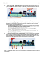
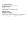
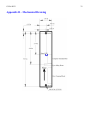
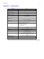
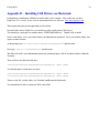
User Manual Version 0.2 G-Wiz HCX 1 Table of Contents Limited Warranty and Disclaimer ....................................................................................................................2 How to contact G-Wiz Partners ........................................................................................................................2 Introduction.......................................................................................................................................................3 Features:............................................................................................................................................................4 Flight Computer Operation ...............................................................................................................................5 Quick Start Hardware Configuration ................................................................................................................7 Easy Guide for Launch Setups:.........................................................................................................................8 1 Dual parachute deployment using one 9v. battery (No clustering or staging). ........................8 2. Dual parachute deployment with dual batteries (No clustering or staging). ..........................10 3. Second Stage plus dual parachute deployment with dual batteries ........................................11 4. Single parachute deployment at apogee with one 9v. ...............................................................13 5. Cluster ignition, plus single parachute deployment at apogee using dual batteries..............14 Quick Start Software Configuration ...............................................................................................................16 Mounting the Flight Computer .......................................................................................................................18 Hardware.........................................................................................................................................................19 Software ..........................................................................................................................................................22 Configuration.........................................................................................................................................23 Bench Testing .......................................................................................................................................25 Calibration .............................................................................................................................................26 Sensor Statistics...................................................................................................................................27 Firmware Update..................................................................................................................................28 Examining flight Data...........................................................................................................................29 Appendix A – Technical Data.........................................................................................................................30 Appendix B – Mechanical Drawing ...............................................................................................................32 Appendix C - Specifications ...........................................................................................................................33 Appendix D – Installing USB Drivers on Macintosh .....................................................................................34 Appendix E – Installing USB Drivers on Windows XP .................................................................................35 NOTE: This unit has not been tested with Hybrids at this time. We will post hybrid testing info, and a firmware update (if needed) when we have this data. G-Wiz HCX 2 Limited Warranty and Disclaimer G-Wiz Partners warrants the G-Wiz HCX Flight Computers to be free from defects in materials and workmanship and remain in working order for a period of 180 days. If the unit fails to operate as specified, the unit will be repaired or replaced at the discretion of G-Wiz Partners, providing the unit has not been damaged, modified, or serviced by anyone except for the manufacturer. G-Wiz HCX Flight computers are sold as an experimental accessory only. Due to the nature of experimental electronic devices, especially when used in experimental carriers such as rockets, the possibility of failure can never totally be removed. The owners, employees, vendors and contractors of G-Wiz Partners shall not be liable for any special, incidental, or consequential damage or expense directly or indirectly arising from the customer or anyone’s use, misuse, or inability to use this device either separately or in combination with other equipment or for personal injury or loss or destruction of other property, for experiment failure, or for any other cause. It is up to the user, the experimenter, to use good judgment and safe design practices and to properly pre-test the device for its intended performance in the intended vehicle. It is the user or experimenter’s responsibility to assure the vehicle will perform in a safe manner and that all reasonable precautions are exercised to prevent injury or damage to anyone or anything. WARNING: Do not use this device unless you completely understand and agree with all the above statements and conditions. First time use of the G-Wiz HCX Flight Computer signifies the user’s acceptance of these terms and conditions How to contact G-Wiz Partners Please see our website at: http://www.gwiz-partners.com. Our web site has the latest versions of all our user manuals, Device Firmware, FlightView Software updates, and email contact information. G-Wiz HCX 3 Introduction After reading this manual, if you have any questions or problems with either your flight computer or FlightView software, please visit us on the web at: http://www.gwiz-partners.com or write us at: [email protected] or at: G-Wiz Partners, PO Box 320103 Los Gatos, CA 95032-0101. A FAQ is maintained on the web site, and new versions of FlightView are posted there free for download, as are new versions of HCX Firmware. The G-Wiz HCX flight computers are precision state-of-the-art recording altimeters that utilize dual sensors, both a barometer and accelerometer, to integrate, operate and record flight data for model and high power rockets. These are multi-functional units, with some versions operational within the extraordinary range of +/- 200 G’s of acceleration; the basic HCX is capable of +/- 50 G’s. The unique shunt plug in the HCX’s allow the battery power and circuit continuity to be monitored and displayed while still plugged in, yet the charges are made safe. HCX can control flight events for up to three separate flight operations: apogee deployment, low altitude deployment, and cluster or staging. In addition, HCX has a 4th output port that is fully programmable. HCX’s keep track of multiple flights by recording the accelerometer sensor data and the barometric sensor data on a mini-SD card in a normal file system. These files are readable directly by FlightView. HCX’s sophisticated firmware algorithms take full advantage of having a dual sensor system (the on-board accelerometer and barometric pressure sensor). The processor at the heart of these 2nd generation flight computers has an integrated 12-bit A to D converter along with a CPU core executing instructions at a rate of over 8 million instructions per second! They come standard with high current, open drain, power MOSFET channels initiating the pyrotechnic events. The G-Wiz Flight Computers use proprietary firmware algorithms to determine the key events in a rockets trajectory. The key events monitored are: Launch Booster burn-out Sustainer ignition (when applicable) Sustainer burn-out (when applicable) Apogee (both inertial and barometric) Altitude, both rising and falling Landing When used with proper batteries and pyrotechnic devices, these flight computers can air-start clusters or perform flawless staging, deploy a drogue at apogee and a main chute at programmable altitudes. You can also deploy a single chute at apogee. The peak altitude (determined by barometric pressure) is beeped out after the rocket has landed. Flight data analysis is accomplished with our FlightView software, which runs on PC and Power Mac’s (and possibly others upon request). [FlightView is a Java application] FlightView will display the measured flight acceleration, inertial velocity, and barometric altitude in relation to the time in which the various flight events occurred. G-Wiz HCX Features: Beeper to indicate altitude and status, with blue status LED Continuous CPU and Pyro Battery monitoring prior to launch. Continuous continuity monitoring, prior to launch. Jumper to select between Cluster or Stage on Pyro channel 0 When used for Staging, can be set to 1st, 2nd, or 3rd stage. All channels have an optional timer delay before event trigger. 0-25 seconds in .1sec increments On board Safety Shunt, and terminals for optional extern shunt. Single battery, low current mode. Or dual battery high current mode (8A max) Variable recording rate, from 62 sample per second, to 500 samples per second, 12 bits per sample. RS-232 or USB Connections Configurable low-altitude. Can be set in 100 foot/meter increments to 25500 feet / meters. Metric or English for low-altitude configuration and max altitude readout. Reverse protection diode to protect against accidentally connecting a battery backwards. 4th output channel, totally programmable. Optional break-wire use for launch detect. Optional analog input and be recorded and / or used for events. Capable of recording multiple flights. Barometric altitude over 70K feet MSL Maximum acceleration of 56Gs (HCX/50), 112Gs (HCX/100), 168Gs (HCX/150), or 224Gs (HCX/200) Firmware in Flash memory, and upgradeable by user. 4 G-Wiz HCX 5 Flight Computer Operation Power On When First powered on, the LED will light for 1-2 seconds (with no sound), then turns on while the beeper beeps status, and off for continuity checks The normal sequence is: 1. LED ON 2. One or Two low pitch beeps (one for Cluster, 2 for Stage) 3. (If low power on either battery, a quick warble is heard here, after a half second pause) 4. LED OFF 5. Half second pause 6. A single quick “chirp” or double “chirp” for each Pyro ports (one means good continuity) 7. 1 second pause 8. Repeat from 1 Where in step 2, a single beep indicates that pyro 1 will be used for Clustering (i.e. triggered on launch detect), and 2 beeps indicates staging. The “chirps” in step 6 indicate continuity of the pyro ports. Starting with port 1, one chirp is “Good” continuity, 2 chirps is “Bad” continuity. Other possibilities: Power-on self-test failure (POST Failure): 1. Long warble 2. Half second delay 3. 1 – 7 high pitch beeps giving a failure code 4. if 5 or more beeps are heard, there will be another half second delay, then 1-11 low pitch beeps with a secondary code. 5. 1 second pause 6. repeat If this is heard – DO NOT FLY! Record the number of beeps (fail codes), and contact G-Wiz support ([email protected]). Failure codes are given in Appendix A. SD Card un-plugged: 1. Long, High pitch beep 2. Long, low pitch beep 3. 3/4 second delay 4. Normal ‘Power On’ sequence. When there is no SD card, the computer will not be able to record data, but will fire all events. Configured for Break-Wire launch, but break wire not connected at power on: 1. Short warble. 2. 1 second delay 3. repeat. 4. Warning! While in this mode, you will not be able to connect with FlightView. Connect break-wire to continue. G-Wiz HCX 6 Landing After landing, the HCX computer will begin the readout phase by beeps from the piezo beeper. The numbers are beeped out in quick sequences with very brief pauses between each number sequence. ZERO is represented as a long beeeep, 1 is a quick chirp, 2 is 2 chirps, and so on. After the number sequences the unit will pause for ONE FULL SECOND and then repeat the number sequences. For example, 5081 feet of altitude would be represented in beeps by: chirp chirp chirp chirp chirp (5) – beeeep (0) – chirp chirp chirp chirp chirp chirp chirp chirp (8) – chirp (1) – pause – then repeat the sequence, in other words, 5 chirps – quick pause – 1 long beep (for zero) – quick pause – 8 quick chirps – quick pause – 1 chirp – then a full one second pause (noting the end of the sequence) – then repeat the number sequences. If the example is 12,112 feet it would equal: chirp – chirp chirp – chirp – chirp – chirp chirp – pause – repeat sequence. In the Configuration dialog, you can optionally elect to get maximum speed as well. If this option is selected, altitude and speed readouts will alternate. The status LED will be on for the entire airspeed readout, and off for the entire altitude readout. The computer must be turned off (then on) before launching again. Data will not be lost. G-Wiz HCX 7 Quick Start Hardware Configuration There are two jumpers on this computer, one used to switch pyro 1 from cluster to stage use, the other to switch high or low current limit on all outputs. Jumper Functions Jumper position number With Jumper IN JP 2 (Pyro current selection) JP 7 (Cluster or Stage selection) JP 5 (Break wire launch bypass) JP2 – Output Current With Jumper OUT High Current (two batteries only) Low Current (one battery possible) Stage Cluster Break-wire launch detect (TB2-3,4) User analog input (0-5v) (TB2-3,4) JP5 – Break-wire Bypass JP2 / 3 – Safety Shunt JP7 – Cluster / Stage Beeper Photo 1 TB1 TB2 I/O Headers Status LED HCX: Use the following guide to wire batteries, charges and igniters to the terminal bar. JP5 – Serial Communications Nose End G-Wiz HCX 8 Easy Guide for Launch Setups: 1 Dual parachute deployment using one 9v. battery (No clustering or staging). [A single battery powers both the computer and firing devices] 1.1. Run a jumper wire from the “CPU Power” + (or CBatt+) terminal (TB2 Pin 6 on the terminal bars) to the “Pyro Power” + (or PBatt+) terminal (TB1 Pin 10 on the terminal bars) (See photo 1 below) Shunt Plug Jumper Wire Photo 2 1.2. Pull the small twin pin jumper connector OFF of the JP2 twin pins (located near the bottom – and located on the far side from the terminal bar.) This sets it for low pyro current, which is best when using a single battery. [Use Davyfire 28b’s to fire your charges in the low current mode, as any other electric match device will most likely not work – unless using two batteries and the High current mode with the twin pin JP2 jumper ON (See JP2 being removed in photo 3 below) Photo 3 1.3. This is the only jumper you have to deal with for dual deployment with a single battery – all other jumpers should be ON the twin pin connectors. 1.4. Connect the power source, a 9 volt battery (preferably with some type of switch in the circuit), to the nose end of the terminal bar (either TB1 Pins 1 & 2 or TB2 Pins 5 & 6). G-Wiz HCX 9 1.5. With the shunt plug in place (or power disconnected), wire the Drogue chute firing device to the Apogee + and – terminals (TB1 pins 5 and 6) (Davyfire 28b firing devices are not polarity sensitive). (If testing, test lights may not have the proper resistance to signal the LED and beeper) 1.6. Wire the Main chute firing device to the Low Alt + and – terminals (TB1 pins 7 and 8). 1.7. Once all the correct firing devices are hooked up you can test the circuits. Turn on your power switch to the altimeter with the shunt plug plugged in. Once you’ve tested it by listening to the beep sequence or observing the status LED, you can either leave it on or turn it off until the rocket is mounted on the pad. The launch sensor is pretty robust and the shunt plug will not allow the charges to fire. When you turn on the power to the altimeter the beeper and status LED will: Emit a two quick tones (signaling the battery is OK, and that the cluster/stage jumper is set to stage) If not, check the beep pattern in the Operation section, above (Page 5). Then emit two chirps (signaling the cluster and staging channel has nothing connected to it) Then emit a single chirp (signaling the apogee channel firing device, a Davyfire N28B has continuity). Two quick tones means there is No continuity. Then emit a single chirp (signaling the main chute channel Davyfire N28B has continuity). Two quick tones means there is No continuity. Then emit two chirps (signaling the user channel has nothing connected to it) Then it will pause and cycle the beep pattern again. 1.8. Photo 4 below shows the altimeter connected to a single battery, and set to deploy a drogue at apogee and a main at 800 feet (the default). Be sure to remove the red shunt plug JP1/3 only when the rocket is mounted on the pad and ready to launch. Photo 4 Note -- If your application does not allow use of the shunt plug the unit must be tested by power on, then shut off until on the pad G-Wiz HCX 10 2. Dual parachute deployment with dual batteries (No clustering or staging). [One battery powers the computer and one powers the pryo channels] 2.1 To use a dual battery setup DO NOT use a jumper wire from the computer battery + (CBatt+) (TB2 pin 6) to the pyro battery +(PBatt+) (TB1 pin 1) terminals. Connect two batteries. A 9 volt battery for the computer should be wired to the “nose end” of terminal bar 2 (TB2) (positive + to CBatt+ Pin 6 and negative – to CBatt- Pin 5) (which should have some method to switch the power to the computer on and off). A second battery (9 to 15 volts) should be wired to the pyro power terminals terminal bar 1 (TB1), designated as “pyro” (+ to PBatt+ Pin 1, and – to PBatt- Pin 2). 2.2 The small twin pin jumper at JP2 should be ON the pins (located near the bottom – and on the far side from the terminal bar.) This sets the altimeter for high pyro current, which should only be used in the dual battery configuration. (See photo 5) Photo 5 2.3 This is the only jumper you have to deal with for normal single motor launches with dual deployment parachutes, even though you’re using dual batteries. 2.4 Once all the correct firing devices are hooked up you can test the circuits. Turn on your power switch to the altimeter with the shunt plug plugged in. Once you’ve tested it by listening to the beep sequence or observing the status LED, you can either leave it on or turn it off until the rocket is mounted on the pad. The launch sensor is pretty robust and the shunt plug will not allow the charges to fire. When you turn on the power to the altimeter the beeper and status LED will: Emit a two quick tones (signaling the battery is OK, and that the cluster/stage jumper is set to stage) If not check the beep pattern in the Operation section, above (Page 5). Then emit two chirps (signaling the cluster and staging channel has nothing connected to it) Then emit a single chirp (signaling the apogee channel firing device, a Davyfire N28B has continuity). Two quick tones means there is No continuity. Then emit a single chirp (signaling the main chute channel Davyfire N28B has continuity). Two quick tones means there is No continuity. Then emit two chirps (signaling the user channel has nothing connected to it) Then it will pause and cycle the beep pattern again. 2.5 In photo 6 the altimeter is connected to separate batteries to power the computer and the pryo channels. Charges are wired to deploy both apogee and low altitude parachutes (main set at the default of 800 feet). Be sure to remove the red shunt plug JP1/3 only when the rocket is mounted on the pad and ready to launch. G-Wiz HCX 11 Photo 6 Note -- If your application does not allow use of the shunt plug the unit must be tested by power on, then shut off until on the pad. 3. Second Stage plus dual parachute deployment with dual batteries [One battery powers the computer and one powers the pryo channels] 3.1. To use a dual battery setup DO NOT use a jumper wire from the computer battery + (CBatt+) (TB2 pin 6) to the pyro battery +(PBatt+) (TB1 pin 1) terminals. Connect two batteries. A 9 volt battery for the CPU should be wired to the “nose end” of terminal block 2 (TB2) (positive + to CBatt+ Pin 6 and negative – to CBatt- Pin 5) (which should have some method to switch the power to the computer on and off). A second battery (9 to 15 volts) should be wired to the pyro power terminals terminal bar 1 (TB1), designated as “pyro” (+ to PBatt+ Pin 1, and – to PBatt- Pin 2). In the Staging mode the unit fires an ignition device for the staging motor (or motors) when it detects motor burnout of the booster motor (or motors). In the Cluster mode the unit fires the cluster motor (or motors) as soon as it detects and confirms launch, which occurs at approximately 0.5 seconds from the first movement of the rocket. Consider that there is also a delay factor from the time the igniter fires until the time the motor (or motors) actually ignite. 3.2. The small jumper connector should be ON the JP2 twin pins (located near the bottom – and located on the far side from the terminal bar). This sets it for High pyro current (which is required when setting the altimeter for any type of staging or clustering). (See photo 7 below) Photo 7 G-Wiz HCX 3.3. 12 Set the system to stage. Staging (JP7 ON) fires a motor (or motors) when the booster burns out. Set it to stage by plugging in the JP7 twin pin jumper. The JP7 jumper is located just forward of the status LED opposite the terminal bar side of the board. (See photo 8 below) Photo 8 3.4. Once all the correct firing devices are hooked up you can test the circuits. Turn on your power switch to the altimeter with the shunt plug plugged in. Once you’ve tested it by listening to the beep sequence or observing the status LED, you can either leave it on or turn it off until the rocket is mounted on the pad. The launch sensor is pretty robust and the shunt plug will not allow the charges to fire. When you turn on the power to the altimeter the beeper and status LED will: Emit two quick tones (signaling the battery is OK, and that the cluster/stage jumper is set to stage) If not, check the beep pattern in the Operation section, above (Page 5). Then emit a single chirp (signaling the cluster and staging channel firing device, a Davyfire N28B has continuity). Two quick tones means there is No continuity. Then emit a single chirp (signaling the apogee channel firing device, a Davyfire N28B has continuity). Two quick tones means there is No continuity. Then emit a single chirp (signaling the main chute channel Davyfire N28B has continuity). Two quick tones means there is No continuity. Then emit two chirps (signaling the user channel has nothing connected to it) Then it will pause and cycle the beep pattern again. 2.1 In photo 9 the altimeter is connected to separate batteries to power the computer and the pryo channels, charges are wired for apogee and low altitude deployment (in this case, the default 800 feet) and a stage sequence (JP7 ON) (which fires when the altimeter senses the booster motor burnout). Be sure to remove the red shunt plug JP1/3 only when the rocket is mounted on the pad and ready to launch. Photo 9 Note -- If your application does not allow use of the shunt plug the unit must be tested by power on, then shut off until on the pad G-Wiz HCX 13 4. Single parachute deployment at apogee with one 9v. Follow the instructions in section 1.1 just as you would when setting up for dual deployment with a single battery. The only difference is that there is but one firing device to connect. Omit step 6 (connecting a device to the low altitude pyro ports). With the shunt plug in place (or power disconnected), be sure you connect your firing device to the Apogee + and – terminals (pin 3 and 4) [Use Davyfire 28b’s to fire your charges in the low current mode, as any other electric match device will most likely not work – unless using two batteries and the High current mode with the twin pin JP1 jumper ON] Once all the correct firing devices are hooked up you can test the circuits. Turn on your power switch to the altimeter with the shunt plug plugged in. Once you’ve tested it by listening to the beep sequence or observing the status LED, you can either leave it on or turn it off until the rocket is mounted on the pad. The launch sensor is pretty robust and the shunt plug will not allow the charges to fire. When you turn on the power to the altimeter the beeper and status LED will: Emit two quick tones (signaling the battery is OK, and that the cluster/stage jumper is set to stage) If not, check the beep pattern in the Operation section, above (Page 5). Then emit two chirps (signaling the cluster and staging channel has nothing connected to it) Then emit a single chirp (signaling the apogee channel firing device, a Davyfire N28B has continuity). Two quick tones means there is No continuity. Then emit a single chirp (signaling the main chute channel Davyfire N28B has continuity). Two quick tones means there is No continuity. Then emit two chirps (signaling the user channel has nothing connected to it) Then it will pause and cycle the beep pattern again. Photo 10 below shows the altimeter set to be powered by a single battery and wired up and set to deploy a single parachute at apogee. Be sure to remove the red shunt plug JP1/3 only when the rocket is mounted on the pad and ready to launch. Photo 10 Note -- If your application does not allow use of the shunt plug the unit must be tested by power on, then shut off until on the pad. G-Wiz HCX 14 5. Cluster ignition, plus single parachute deployment at apogee using dual batteries [One battery powers the computer and one powers the pryo channels] To use a dual battery setup DO NOT use a jumper wire from the computer battery + (CBatt+) (TB2 pin 6) to the pyro battery +(PBatt+) (TB1 pin 1) terminals. Connect two batteries. A 9 volt battery for the computer should be wired to the “nose end” of terminal block 2 (TB2) (positive + to CBatt+ Pin 6 and negative – to CBatt- Pin 5) (which should have some method to switch the power to the computer on and off). A second battery (9 to 15 volts) should be wired to the pyro power terminals terminal block 1 (TB1), designated as “pyro” (+ to PBatt+ Pin 1, and – to PBatt- Pin 2). In the Staging mode the unit fires an ignition device for the staging motor (or motors) when it detects motor burnout of the booster motor (or motors). In the Cluster mode the unit fires the cluster motor (or motors) as soon as it detects and confirms launch, which occurs at approximately 0.5 seconds from the first movement of the rocket. Consider that there is also a delay factor from the time the igniter fires until the time the motor (or motors) actually ignite. 5.1. The small jumper connector should be ON the JP2 twin pins (located about ⅓ the way up the board from the bottom – and located on the far side from the terminal bar.) This sets it for High pyro current (which is required when setting the altimeter for any type of staging or clustering). (See photo 11 below) Remove Photo 11 5.2. Set the system to Cluster. When Cluster firing (JP7 OFF) motor(s) the igniters will fire at 0.5 seconds after the rocket begins moving (the ignition of motors usually lags behind this). Set the altimeter for clusters by removing the jumper from JP7 twin pins. The JP7 jumper is located just forward of the status LED opposite the terminal bar side of the board. (See photo 12 below) Remove Photo 12 5.3. Once all the correct firing devices are hooked up you can test the circuits. Turn on your power switch to the altimeter with the shunt plug plugged in. Once you’ve tested it by listening to the beep sequence or G-Wiz HCX 15 observing the status LED, you can either leave it on or turn it off until the rocket is mounted on the pad. The launch sensor is pretty robust and the shunt plug will not allow the charges to fire. When you turn on the power to the altimeter the beeper and status LED will: Emit one long tone (signaling the battery is OK, and that the cluster/stage jumper is set to cluster) If not, check the beep pattern in the Operation section, above (Page 5). Then emit a single chirp (signaling the cluster and staging channel firing device, a Davyfire N28B has continuity). Two quick tones means there is No continuity. Then emit a single chirp (signaling the apogee channel firing device, a Davyfire N28B has continuity). Two quick tones means there is No continuity. Then emit two chirps (signaling the main chute channel has nothing connected to it Then emit two chirps (signaling the user channel has nothing connected to it) Then it will pause and cycle the beep pattern again. 5.4. In photo 13 the altimeter is connected to separate batteries to power the computer and the pryo channels, charges are wired for apogee and low altitude deployment (in this case, the default 800 feet) and a stage sequence (JP7 OFF) (which fires when the altimeter senses the booster motor burnout). Be sure to remove the red shunt plug JP1/3 only when the rocket is mounted on the pad and ready to launch. Photo 13 Note -- If your application does not allow use of the shunt plug the unit must be tested by power on, then shut off until on the pad. G-Wiz HCX 16 Quick Start Software Configuration By default, the HCX computer comes configured to behave like other G-Wiz flight computers. Staging is for first stage, low altitude in 800 ft. English units are used, no delays are used. If this is what you want, no more need be done. To change something: 1. Make Sure that FlightView is installed on your computer, and that you have an available serial port and G-Wiz serial interface or an available USB port and G-Wiz USB interface.. a. Insert CD-Rom and open “Install.html” or go to http://www.gwizpartners.com/Downloads/install/install.html using your computer’s browser. b. Follow the instructions to install FlightView for your computer. 2. (Optional) Connect G-Wiz USB interface. a. Connect interface board to Flight Computer by inserting the 8 pin connector (JP6) to the matching socket on the HCX. See photo 14 below. b. Connect USB Cable to interface board and computer. c. Connect power to the HCX. d. The install process places the drivers for your machine in a directory under your install directory. Under Windows, a dialog will appear asking how to install the drivers. Do not search the internet, or the computer. Instead, elect to tell it where the drivers are. If you installed at the default location, this will be: C:\Program Files\GWizViewer\usbDrivers. This process is shown in detail for Windows XP in Appendix E. Macintosh users should follow the procedure in described in Appendix D. 3. (Optional) Connect G-Wiz RS-232 serial interface. a. Connect interface board to Flight Computer by inserting the 8 pin connector (JP6) to the matching socket on the HCX. See photo 14 below. b. Connect power to HCX. c. Connect a Straight Through serial cable between interface and computer. Note that this is different then the original HCX. Photo 14 4. Run FlightView a. Select “G-Wiz / Connect” from the menus. A dialog will appear asking which port the G-Wiz is connected to. Note that the USB interface will install as a serial port. On a PC, it will generally be a COM port larger then “4”. b. Choose the correct port, and click “OK”. It should say “connected to G-Wiz HCX” in the bottom left of the screen. G-Wiz HCX c. d. e. f. 17 Select “G-Wiz / Configure”. The following Dialog Box will appear, allowing you to change the pyro port configuration. See the “FlightView : Configuration” later in this manual for details. Press “Upload & Exit” when done. The new configuration will not be loaded until the Flight Computer has been turned off, then on again. g. More detail is given in the “Software” section. G-Wiz HCX 18 Mounting the Flight Computer The flight computer must be mounted in the correct orientation to operate. It will NOT operate otherwise. The “nose” end is indicated on the board, but to confirm the orientation, the terminal block should to be at the rear, or aft end (the nose end is also indicated in photo 1). The computer should be mounted lengthwise with the axis of the rocket. It’s designed to be mounted with 4-40 hardware. The computer must also be protected from the ejection gasses. Ejection gasses are corrosive and will damage the flight computer, voiding your warranty. If you are mounting to carbon fiber airframes be certain the shunt plug doesn’t ground to the carbon fiber airframe, as carbon conducts electricity. See the following pictures to confirm the orientation for mounting. Nose end up G-Wiz HCX 19 Hardware The Flight Computer From the top: JP2 – Low Current Jumper JP5 – Breakwire Bypass Cluster Stage Beeper Jumper JP7 Safety Shunt Status LED Terminal Block TB1 Terminal Block TB2 CPU Communications Connector JP6 Pressure Sensor Accelerometer And the bottom: Mini-SD Card Socket MOSFETs Major components: CPU – The microprocessor that controls everything. The “Brain” of the Flight Computer. Mini-SD Card Socket – Insert an Mini-SD card to store flight data. MOSFET – The are 1 of these for every pyro port (plus a few more). They are capable of switching up to 8 amps of current if the pyro battery used can supply it. G-Wiz HCX 20 Accelerometer – The sensor used to measure acceleration. Pressure Sensor – Used to measure barometric pressure. Barometric pressure is used to calculate the pressure altitude of the rocket, based on the NASA Standard Atmosphere Model. Terminal Blocks – Used connect wires to the Flight Computer. Electric matches, etc. Batteries in the 9-12v range should be used for both pyro and CPU power. The “break wire” and “external shunt” connections are basically switch inputs. Connecting a wire between the two terminals of the “external shunt” is the same as inserting the shunt into the red connectors. This connection must be broken for the pyro ports to be functional. The “break wire” input is similar. Connect a wire between these two terminals, and power the computer on. If configured, when the wire is broken (switch opened), launch will be detected. If not configured, an event will be generated instead. JP1 & JP3 – Safety shunt. If the safety pin is inserted into these connectors, the pyro ports will be unable to fire. They can still detect continuity, however. JP2 – High Current jumper. With this jumper OUT, the computer will be in low power mode, which limits the current to each pyro port to 1 amp. This is sufficient for low current electric matches, such as the DaveyFire 28B. In low current mode, one battery can safely be used, and a wire jumper connected between pyro and CPU battery “+” terminals. We recommend using the Bench Test feature (described later) to test electric matches before flight. nd rd JP7 – Cluster / Stage jumper. When IN, pyro 0 will fire at burnout (or the 2 or 3 burnout, depending on config). When OUT, pyro 0 will fire when launch is detected, approximately half a second into the flight. JP6 – Communications interface socket. Connects to either the G-Wiz USB interface or G-Wiz RS-232 interface. JP5 – Break-wire bypass. Jumper should be IN when using a break-wire for launch detect, and out when using the aux input as a third analog channel for recording. Beeper – Used to indicate status audibly. Status LED – Used to give a visual status indication. Using the Safety Shunt The HCX has 2 Safety shunt inputs: The JP 1 / 3 pair, and terminals 1 & 2 of Terminal block 2. These are parallel inputs, and are identical. The built-in shunt (JP 1 / 3) should be used if the unit is mounted near enough to the airframe that the shunt can be inserted through a hole. If this is not possible, you may mount an external shunt in or near the airframe, and wire it to the Terminal Block. In normal use, the shunt should be inserted before the unit is powered on, and should be removed after all other prep work on the pad. Removing this shunt arms the pyro outputs, enabling them to fire when signaled. Using a Break Wire HCX has a fairly stiff requirement for launch detect, require about 2.5g for half a second or so. Higher accelerations will result in shorter detect times, but even a 50g launch will need about a tenth of a second. If your launch will be faster (some zinc – sulfur rockets have very high G thrusts for very short periods), or slower (low thrust to weight) then this, you can use a break-wire for launch detect. The wire should be connected between terminal bock 2’s pins 3 & 4 (aux input), and be placed across the nozzle of the motor, or other location where launch will cause the wire to break. HCX needs to be configured for this type of launch (See figure 3, below), and JP5 should be IN. If not configured as a launch detect, this input can be used as an analog input for another sensor that outputs in 0-5v range. JP5 should be OUT for this. Linking to a PC Connect to an available RS232 serial (COM) port on your computer using a 9-pin male to female subminiature ‘D’ connector cable wired straight through (also known as a “serial printer cable”). These cables are readily available at most computer stores. G-Wiz HCX 21 Linking to an iMac or Power Mac If you are using a MAC, you’ll want to use the G-Wiz USB interface. The driver for this should have been installed when FlightView 2.x was installed. If not, look in the FlightView CD under the “Drivers:OS X” or “Drivers:OS9” directory. Connect a 9 volt battery to the altimeter. Power up the G-Wiz flight computer. You’ll hear a series of beeps (it will quit once you’ve linked to the software). If using a single 9 volt battery connect it to the PBatt+ (TB1 pin 10) and PBatt– (TB1 pin 9) terminals, taking care to be sure the polarity is correct. Connect a jumper wire from the PBatt+ (TB1 pin 10) on the terminal block to the CBatt+ (TB2 pin 6) terminal, just as you would for any single battery use (see photo 10). If using dual batteries, connect one 9 volt battery to the PBatt + (TB1 pin 10) and – (TB1 pin 9) terminals, taking care to be sure the polarity is correct. Then connect another to the CBatt + (TB2 pin 6) and – (TB2 Pin 5) terminals (in this situation do not use a jumper wire). In other words, connect the batteries just as you would for any dual battery use. Again, take care to be sure the polarity is correct to each battery. See photo 13. Using the Mini-SD card To read recorded during a flight, remove the mini-SD card, and insert it into your computer running FlightView. Use the File ‘Open…’ menu item to open the data file. Because the computer can record at a very high data rate, the computer will pre-allocate a large (size configurable) file on the SD card. It also requires that this file has no ‘fragments’. I.E. that it be continuous on disk. Because of these requirements, it is recommended that a freshly formatted card be used for each series of flights. The flight computer will sound an error code if it cannot allocate a file meeting these requirements. G-Wiz HCX 22 Software FlightView HCX Features Starting with version 2.8 FlightView supports HCX configuration and data viewing, in addition to its base feature set. Before you try to connect, Select ‘Preferences…’ from the File menu, and you will see a dialog like that in figure 1. Figure 1 Setect the COM port you will be using with the combo box provided. Decide on any other preferences you wish to set as well. Then select ‘Connect…’ from the G-Wiz menu, and you should see a message at the bottom of the window with the model of flight computer connected to, and your computer should stop beeping. When Connected, The G-Wiz Menu will have several additional items: The additional menu items allow you to: Configure the computer Calibrate the accelerometer Bench Test the computer Get Statistical Data on the Sensors. Upgrade the Firmware Scale data recorded on the optional analog channel. G-Wiz HCX 23 Configuration The configuration item will read the configuration memory of HCX, and display it in the dialog shown in Figures 2 & 3: Figure 2 The ‘Main’ tab of the configuration dialog if for making global settings, divided into 3 groups: Aux Input, Data File, and Miscellaneous. The Aux Input section determines if a break-wire should be used for launch detect, or if the input should be used to record user-determined sensor data. If recording an additional analog channel, data from that channel may also be used to trigger events. The Data File section is used to set the time-stamp used when files are saved on SD card by the computer, the maximum size used, and the root file name to use. The max file size is entered because the HCX preallocates the file before flight. It does this so that unexpected events that disrupt the flight will not disrupt the file writing (at least as much as possible). The file size can be set in bytes, or by number of seconds to record. The Miscellaneous section allows the sample rate to be selected, as well as the desire for maximum speed readout, and the measurement system to use (English vs SI). . G-Wiz HCX 24 Figure 3 The ‘Output’ tab of the Configuration Dialog allows you to determine when each output should fire. It is divided by port, as each port has a specific function. Pyro 1 is used for igniting a Cluster at liftoff (JP7 OUT) or Staging (JP7 IN). You can add a delay of 0-25 seconds (fractions permitted) between the event, and the firing of the port. You can also set which stage to fire, when JP7 is IN - 1st, 2nd, or 3rd, corresponding to how many "burnout" events to look fore before firing. Pyro 2 is used for Apogee deployment. You can specify a delay, as above, and you can specify whether to use Inertial Apogee (RECOMMENDED) or Barometric Apogee. Using Barometric Apogee is useful in strapon boosters and other situations where tumbling may occur. Tumbling confuses the inertial apogee algorithm. Pyro 3 is used for Main deployment. You have two choices - you can set an altitude to deploy at from 100 to 25500 feet or meters (based on selection of Meters check-box, below) in increments of 100, and you can add a delay as well. Or you can deploy the main a given time after (inertial) apogee. This is a special feature included for the ARLISS flights, but may also be useful to provide 2 stage deployment in conditions where the computer cannot be exposed to atmospheric pressure. Pyro 4 is totally open. You can select an event causing it to turn on, and a different event (or the same, plus a delay) to turn it off. Delays are possible for both on and off events. Some events may require additional information, which can also be supplied. Available events are: o Launch Confirmed o Burnout N (Nth Burnout) o Stage N (Nth acceleration) o Inertial Apogee o Barometric Apogee o Ascending above <Altitude> o Descending below <Altitude> o Landed o Analog input <, >, ==, or != a set value G-Wiz HCX 25 After uploading the new configuration, the Flight Computer must be turned off, and on again before the new configuration will be used. Bench Testing The Bench Test item will scan the sensors and ports of HCX, then display this dialog in Figure 6: Figure 4 This window shows the current values of all sensors, and the continuity state of the pyro outputs. In addition, there is an 'indicator light' to tell you the relative quality of that value. Green is good, Red bad, and Yellow questionable. Note that open pyro ports will generate yellow indicators, as there is probably legitimately nothing in them. Continuity reads as “Good” if the igniter value is between 0 and 30 ohms. You may also selectively arm and fire the pyro channels to test battery power or igniters. Pressing the 'Update' button will cause all values to be re-read. For the sensor self-tests, the barometer should read somewhere in the area of 100kPa +- 20kPa. Acceleration -1 to +1 g depending on computer orientation, and accelerometer self test status should be at 12g +- 2gs. In addition, the Test Flight button may be pressed, bringing up a dialog allowing a simple fake inertial test flight to be flown. See Figure 7. G-Wiz HCX 26 Figure 5 This window can be used to initiate a simple 2 stage, inertial only test flight, and follow its progress. When "Start" is pressed, the Flight Computer will start beeping again, as if it were on the pad. It will stop when it recognizes launch. This will test all the inertial related systems in the computer (except the accelerometer itself) - it is being fed fake acceleration values, but otherwise behaves as if they are real. You may connect electric matches, or lights to the pyro ports to watch them activate. The "LED"s in the window will "light" when each stage of flight is recognized. After landing, altitude readout will happen briefly. At this point, you should disconnect FlightView from the Flight Computer, and the Flight Computer turned off, then on again. It has flown a flight, and does not think it is connected anymore. Calibration Figure 8 shows the “Calibrate Accelerometer” dialog. It is fairly self-explanatory. This doesn’t need to be done very often, but should be done at least once. . Figure 6 G-Wiz HCX 27 Sensor Statistics This is a tool that exists just to satisfy your curiosity. There are 4 analog inputs on the HCX, and this menu item displays a dialog (see Figure 9) that lets you choose one, and display data from that sensor continuously as a Graph (Figure 10) or as a Histogram (Figure 11), along with accumulated statistical data. Data shown includes: Current – The value just read. Mean – That statistical mean of the last 100 samples. Std. Dev. – The Standard Deviation of the last 100 samples. Std. Variance – The Standard Variance of the last 100 samples. ENOB – The Effective Number of Bits. Essentially, a measure of how clean the data is. Figure 7 Figure 8 G-Wiz HCX 28 Figure 9 Firmware Update This is the item we hope you will need least. From time to time, we may discover bugs in the HCX, or even want to add features. HCX is capable of having its firmware upgraded by the customer. When we have an upgrade, it will be available on our Web site (http://www.gwiz-partners.com) as a free download. It will very likely be archived in a ZIP file, and therefore need to be un-archived before loading. This menu item will display a common file dialog (see Figure 12) allowing you to load a firmware update file. It is very important that during the update process, nothing disturb either computer. If something should happen or the update fail, don’t panic. Power cycle the HCX, and try again. Multiple failures should they occur, should be reported. It is possible, if the update was interrupted, that after a power cycle, the HCX doesn’t beep its usual pattern, but just sits there, with the LED flashing. That’s OK, it should still connect, though the only thing you will be able to do is “update”. Figure 10 G-Wiz HCX 29 Examining flight Data After the flight computer’s mini-SD card has been transferred to a PC (or Mac), FlightView can open the recorded files by selecting the File ‘Open…’ menu item. The file data is displayed in a dialog like that in Figure 13, below. This dialog contains a lot of information, including general flight data that can be edited, and saved. (Flight date, motors used, etc.). Figure 13 The data can be ‘Zoom’ed in on by highlighting (mouse-drag) the time range to zoom in on. The magnifying glass icon in the lower left corner can be used to return to the original time range. Below the graph data is a legend of symbols used to to mark the events recorded during flight. G-Wiz HCX 30 Appendix A – Technical Data The ‘Save As…’ function in FlightView 2.8 or later can create a text files with raw sensor data. For HCX, from 62 to 500 rows of data are issued in one second. In general, these are raw sensor readings in decimal, and need more information to interpret. See “How Flight Computers Work” for details of how to interpret this data. It is on our website at: http://www.gwiz-partners.com/Tech/Flight_Computers.pdf. Column 1 is acceleration data in the range 0 to 4095 (12 bits), representing accelerations from -56g to 56g (on a HCX/50) with 0g generally around 2048. The sensor used is the Motorola 2202D on the HCX/50, with others used for higher G units. You should locate the data sheets for these sensors, but the core information is: Specification Full Scale Range Full Scale Span Sensitivity Offset (0g) MMA2202 +-56g 4.48v 40mV/g 2.5v Nominal (2.35v-2.65v) MMA2204 +-112g 4.48v 20mV/g 2.5v Nominal (2.35v-2.65v) Higher G units will have data scaled as appropriate (i.e. 112g unit will have data in the range 0 to 8191, with 0g at about 4096). Column 2 is barometric pressure data, also in the range 0 to 4095 (12 bits). This represents pressure data from approximately 0 to 14.5 lbs per square inch (or 0 to 100 kPa). The data sheet gives pressure in ‘kilo Pascals’, where 1kPa = .145psi. The sensor used here is the MPX2102A by Motorola, connected to a now-noise op-amp. Pressure readings start high, and go down as altitude goes up. This is a milli-volt output sensor, and is amplified by 201x before reading. Core information: Specification Full scale range Full scale span Offset Sensitivity (Sensor) Sensitivity (Amplified) MPX2102A 0kPa – 100kPa 20mV 0 .2 mV/kPa 40.28 mV/kPa Column 3 is the “Event” column. It contains a word describing the event (if any) that has occurred as of that reading. These events are, for the most part, self-describing. The one exception is “event(1)”, which is an internal event issued when launch may have occurred, but before it has been validated. We are also experimenting with exporting data in XML format. This file has all relevant data. We may change some tags in the future, but let us know if this is useful for you. POST Failure codes: First set (High Pitch): • 1 beep. Failure reading configuration from EEPROM. • 2 beeps. Sensors reading out of range. • 3 beeps. Accelerometer self-test failure • 4 beeps. Accelerometer status failure • 5 beeps. SD Card initialization error – Secondary code block 1. • 6 beeps. SD File creation error – Secondary code block 2. • 7 beeps. SD File error. Not enough space found on card, try a newly formatted card. G-Wiz HCX 31 Secondary set (Low Pitch), block 1: 1 beep. Failure to reset card. Probable bad card. 2 beeps. Failure to init card. Probable bad card. 3 beeps. Wrong file system on card. Must be formatted as FAT16 or FAT32. 4 beeps. SD Card Read error. Possible bad card. 5 beeps. SD card not FAT formatted. 6 beeps. SD Card partition table bad. 7 beeps. SD Card partition not right type (DOS FAT format) 8 beeps. SD Card Read error. Possible bad card. 9 beeps. SD Card not properly formatted. 10 beeps. SD Card, bad sector size. Must be formatted with 512 byte sectors. 11 beeps. SD Card formatted as FAT12, which is unsupported. Secondary set (Low pitch), block 2: 1 beep. File creation error 1. 2 beeps. SD card full. Try a newly formatted card. 3 beeps. SD Card write error. Try a different card. 4 beeps. SD Card directory error. Try a different card. Unless the failure is due to a SD card problem that can be remedied by changing cards, most POST failures should be reported to G-Wiz support ([email protected]), and you should not fly the computer. G-Wiz HCX Appendix B – Mechanical Drawing 32 G-Wiz HCX 33 Appendix C - Specifications Parameter Max. Acceleration Max. Inertial Altitude (32-bit math) Max. Barometric Altitude (ADC limit – 16-bit math) Number of Pyro Channels Maximum continuous current per Pyro Channel Number of batteries required Recommended Computer Power Battery Max. voltage applied to Computer or Pyro Battery input terminals (TB1, pins 9 & 10 or TB2, pins 5 & 6) Computer current consumption Pyro Channel test current (9VDC battery) Pyro Channel firing time Pyro Channel functions Low Altitude Pyro Channel activation ADC Resolution Sample Rate Altitude readout Number of LEDs Host Computer Interface Main Battery Life (with separate Pyro Battery) Weight (grams) Operating Temp. Range2 1 HCX +/- 56 g 100K+ feet MSL1 70K feet MSL1 4 8 Amps 1 or 2 9 VDC transistor battery (Duracell MN1604) 15 VDC 48mA typ. – idle 100ma typ. – beeper/LED active 3.5mA Channels 1 to 3: Configurable Channel 4: on and off separately programmed 1: Stage(1, 2, or 3)/cluster, 2: Apogee parachute deployment, 3: Low altitude parachute deployment, 4: Event Programmable User Programmable (+/- 50 feet) 12-bits Variable from 62 to 500 samples/second/sensor Status LED and acoustic beeper (Barometric Altitude) 1 Status LED (Continuity and battery voltage) USB 2.0 (TTL/CMOS to G-Wiz USB-Serial Interface Adapter) RS-232 (TTL/CMOS to G-Wiz RS-232 Interface Adapter) 4 hours 36.5 grams 0-80°C Flights over 30,000 feet MSL require HCX to be coated with a special epoxy coating. The coating protects the circuit board and components from condensing moisture. This also insures proper electrical operation of HCX. Please contact G-Wiz Partners for special order options. G-Wiz HCX 34 Appendix D – Installing USB Drivers on Macintosh Unfortunately, installing the USB drivers on the Mac is a bit complex. First, make sure you have FlightView 2.21 or later. If not, it can be downloaded from our web-site: www.gwiz-partners.com. These instructions may not be applicable to newer Macs. Open the folder where FlightView was installed, usually Applications:GWizViewer You should see a package icon with the name “FTDIUSBSerialDriver”. Double click to install. Next is a bit harder. First, you need to know your administrator password. Go to your utilities folder, and open a terminal window. At the prompt, type: “cd /Library/StartupItems/FTDIReEnumerate” and hit return. Now type “sudo pico FTDIReEnumerate” and hit return. The Mac will ask for your administrator password, and then display a file in an editor window within the Terminal. There will be a line that looks like this: /Library/StartupItems/FTDIReEnumerate/ReEnumerate –v0403 –p6001 You should replace it with these two lines: /Library/StartupItems/FTDIReEnumerate/ReEnumerate –v0403 –pEE18 /Library/StartupItems/FTDIReEnumerate/ReEnumerate –v0403 –pDA38 Then save the file, exit the editor, exit Terminal, and Restart the Macintosh. You should now be able to connect to HCX using USB. G-Wiz HCX 35 Appendix E – Installing USB Drivers on Windows XP Windows XP seems to be harder for people to install our drivers on, so here is something of a guided tour. When our USB board is first connected, Windows XP will display a dialog like this: Select ‘No, not at this time’, as shown, and press ‘Next >’. Windows XP will now display this dialog: G-Wiz HCX 36 Again, select ‘Install from a list or specific location (Advanced)’ as shown, and click ‘Next >’. Windows will now display this dialog: G-Wiz HCX Again , as shown, select ‘Search for the best driver in these locations.’ And ‘Include this location in the search’. De-select any other choices. In the edit field, use ‘Browse’ or type in the location of the GWizViewer install directory, and the ‘usbDrivers’ directory under it. The location shown here is the default install location, if your main disk is ‘H’. Finally, Windows XP will display a dialog like this: Just press ‘Continue Anyway’ and installation should continue. This whole process will happen twice – just follow the same directions both times. That’s it! 37