1
Kinetis SDK v.1.3 Demo Applications
User’s Guide
Freescale Semiconductor, Inc.
Document Number: KSDK13DEMOUG
Rev. 0
Sept 2015
Kinetis SDK v.1.3 Demo Applications User’s Guide
ii
Freescale Semiconductor
Contents
Chapter 1
Introduction
Chapter 2
ADC Hardware Trigger Demo
2.1
2.1.1
2.1.2
2.1.3
2.1.4
Overview . . . . . . . .
Trigger by PIT . . . .
Trigger by PDB . . .
Trigger by LPTMR .
Input signal for ADC
.
.
.
.
.
3
3
3
3
4
2.2
Supported Platforms . . . . . . . . . . . . . . . . . . . . . . . . . . . . . . . . . .
4
2.3
2.3.1
2.3.2
System Requirement . . . . . . . . . . . . . . . . . . . . . . . . . . . . . . . . . .
Hardware requirements . . . . . . . . . . . . . . . . . . . . . . . . . . . . . . .
Software requirements . . . . . . . . . . . . . . . . . . . . . . . . . . . . . . . .
6
6
6
2.4
2.4.1
2.4.2
Getting Started . . . . . . . . . . . . . . . . . . . . . . . . . . . . . . . . . . . . .
Hardware configuration . . . . . . . . . . . . . . . . . . . . . . . . . . . . . . .
Prepare the Demo . . . . . . . . . . . . . . . . . . . . . . . . . . . . . . . . . .
6
6
7
2.5
Run the demo . . . . . . . . . . . . . . . . . . . . . . . . . . . . . . . . . . . . .
7
2.6
2.6.1
2.6.1.1
2.6.1.2
2.6.2
2.6.3
2.6.4
2.6.5
Customization Options . . . . . .
Default configurations . . . . . .
ADC configurations . . . . .
Sample frequency . . . . . . .
Configure the number of samples
Configure the signal frequency .
Configure the ADC instance . . .
Configure the ADC input pin . .
7
7
7
8
8
8
8
8
.
.
.
.
.
.
.
.
.
.
.
.
.
.
.
.
.
.
.
.
.
.
.
.
.
.
.
.
.
.
.
.
.
.
.
.
.
.
.
.
.
.
.
.
.
.
.
.
.
.
.
.
.
.
.
.
.
.
.
.
.
.
.
.
.
.
.
.
.
.
.
.
.
.
.
.
.
.
.
.
.
.
.
.
.
.
.
.
.
.
.
.
.
.
.
.
.
.
.
.
.
.
.
.
.
.
.
.
.
.
.
.
.
.
.
.
.
.
.
.
.
.
.
.
.
.
.
.
.
.
.
.
.
.
.
.
.
.
.
.
.
.
.
.
.
.
.
.
.
.
.
.
.
.
.
.
.
.
.
.
.
.
.
.
.
.
.
.
.
.
.
.
.
.
.
.
.
.
.
.
.
.
.
.
.
.
.
.
.
.
.
.
.
.
.
.
.
.
.
.
.
.
.
.
.
.
.
.
.
.
.
.
.
.
.
.
.
.
.
.
.
.
.
.
.
.
.
.
.
.
.
.
.
.
.
.
.
.
.
.
.
.
.
.
.
.
.
.
.
.
.
.
.
.
.
.
.
.
.
.
.
.
.
.
.
.
.
.
.
.
.
.
.
.
.
.
.
.
.
.
.
.
.
.
.
.
.
.
.
.
.
.
.
.
.
.
.
.
.
.
.
.
.
.
.
.
.
.
.
.
.
.
.
.
.
.
.
.
.
.
.
.
.
.
.
.
.
.
.
.
.
.
.
.
.
.
.
.
.
.
.
.
.
.
.
.
.
.
.
.
.
.
.
.
.
.
.
.
.
.
.
.
.
Kinetis SDK v.1.3 Demo Applications User’s Guide
Freescale Semiconductor
iii
Section number
Title
Page
Chapter 3
ADC Low Power Demo
3.1
Overview . . . . . . . . . . . . . . . . . . . . . . . . . . . . . . . . . . . . . . . .
9
3.2
Supported Platforms . . . . . . . . . . . . . . . . . . . . . . . . . . . . . . . . . .
9
3.3
3.3.1
3.3.2
System Requirement . . . . . . . . . . . . . . . . . . . . . . . . . . . . . . . . . . 10
Hardware requirements . . . . . . . . . . . . . . . . . . . . . . . . . . . . . . . 10
Software requirements . . . . . . . . . . . . . . . . . . . . . . . . . . . . . . . . 10
3.4
3.4.1
3.4.2
Getting Started . . . . . . . . . . . . . . . . . . . . . . . . . . . . . . . . . . . . . 10
Prepare the Demo . . . . . . . . . . . . . . . . . . . . . . . . . . . . . . . . . . 10
Run the demo . . . . . . . . . . . . . . . . . . . . . . . . . . . . . . . . . . . . 10
Chapter 4
AFE Qtimer Demo
4.1
Overview . . . . . . . . . . . . . . . . . . . . . . . . . . . . . . . . . . . . . . . . 13
4.2
Supported Platforms . . . . . . . . . . . . . . . . . . . . . . . . . . . . . . . . . . 13
4.3
4.3.1
4.3.2
4.3.3
Getting Started . . .
Hardware Settings
Prepare the Demo
Run the demo . .
.
.
.
.
.
.
.
.
.
.
.
.
.
.
.
.
.
.
.
.
.
.
.
.
.
.
.
.
.
.
.
.
.
.
.
.
.
.
.
.
.
.
.
.
.
.
.
.
.
.
.
.
.
.
.
.
.
.
.
.
.
.
.
.
.
.
.
.
.
.
.
.
.
.
.
.
.
.
.
.
.
.
.
.
.
.
.
.
.
.
.
.
.
.
.
.
.
.
.
.
.
.
.
.
.
.
.
.
.
.
.
.
.
.
.
.
.
.
.
.
.
.
.
.
.
.
.
.
.
.
.
.
.
.
.
.
13
13
14
14
Chapter 5
BLDC Sensorless Demo
5.1
Overview . . . . . . . . . . . . . . . . . . . . . . . . . . . . . . . . . . . . . . . . 17
5.2
Supported Platforms . . . . . . . . . . . . . . . . . . . . . . . . . . . . . . . . . . 17
5.3
5.3.1
5.3.2
System Requirement . . . . . . . . . . . . . . . . . . . . . . . . . . . . . . . . . . 17
Hardware requirements . . . . . . . . . . . . . . . . . . . . . . . . . . . . . . . 17
Software requirements . . . . . . . . . . . . . . . . . . . . . . . . . . . . . . . . 17
5.4
5.4.1
5.4.2
Getting Started . . . . . . . . . . . . . . . . . . . . . . . . . . . . . . . . . . . . . 18
Prepare the Demo . . . . . . . . . . . . . . . . . . . . . . . . . . . . . . . . . . 19
Run the demo . . . . . . . . . . . . . . . . . . . . . . . . . . . . . . . . . . . . 19
Kinetis SDK v.1.3 Demo Applications User’s Guide
iv
Freescale Semiconductor
Section number
Title
Page
Chapter 6
Bubble Level FTM Demo
6.1
Overview . . . . . . . . . . . . . . . . . . . . . . . . . . . . . . . . . . . . . . . . 21
6.2
Supported Platforms . . . . . . . . . . . . . . . . . . . . . . . . . . . . . . . . . . 21
6.3
6.3.1
6.3.2
System Requirement . . . . . . . . . . . . . . . . . . . . . . . . . . . . . . . . . . 21
Hardware requirements . . . . . . . . . . . . . . . . . . . . . . . . . . . . . . . 21
Software requirements . . . . . . . . . . . . . . . . . . . . . . . . . . . . . . . . 21
6.4
6.4.1
6.4.2
Getting Started . . . . . . . . . . . . . . . . . . . . . . . . . . . . . . . . . . . . . 21
Hardware Settings . . . . . . . . . . . . . . . . . . . . . . . . . . . . . . . . . . 21
Prepare the Demo . . . . . . . . . . . . . . . . . . . . . . . . . . . . . . . . . . 22
6.5
Run the demo . . . . . . . . . . . . . . . . . . . . . . . . . . . . . . . . . . . . . 22
Chapter 7
Bubble Level TPM Demo
7.1
Overview . . . . . . . . . . . . . . . . . . . . . . . . . . . . . . . . . . . . . . . . 23
7.2
Supported Platforms . . . . . . . . . . . . . . . . . . . . . . . . . . . . . . . . . . 23
7.3
7.3.1
7.3.2
System Requirement . . . . . . . . . . . . . . . . . . . . . . . . . . . . . . . . . . 23
Hardware requirements . . . . . . . . . . . . . . . . . . . . . . . . . . . . . . . 23
Software requirements . . . . . . . . . . . . . . . . . . . . . . . . . . . . . . . . 23
7.4
7.4.1
7.4.2
Getting Started . . . . . . . . . . . . . . . . . . . . . . . . . . . . . . . . . . . . . 24
Hardware Settings . . . . . . . . . . . . . . . . . . . . . . . . . . . . . . . . . . 24
Prepare the Demo . . . . . . . . . . . . . . . . . . . . . . . . . . . . . . . . . . 24
7.5
Run the demo . . . . . . . . . . . . . . . . . . . . . . . . . . . . . . . . . . . . . 24
Chapter 8
DAC ADC Demo
8.1
Overview . . . . . . . . . . . . . . . . . . . . . . . . . . . . . . . . . . . . . . . . 25
8.2
Supported Platforms . . . . . . . . . . . . . . . . . . . . . . . . . . . . . . . . . . 25
8.3
8.3.1
System Requirement . . . . . . . . . . . . . . . . . . . . . . . . . . . . . . . . . . 25
Hardware requirements . . . . . . . . . . . . . . . . . . . . . . . . . . . . . . . 25
Kinetis SDK v.1.3 Demo Applications User’s Guide
Freescale Semiconductor
v
Section number
8.3.2
Title
Page
Software requirements . . . . . . . . . . . . . . . . . . . . . . . . . . . . . . . . 26
8.4
8.4.1
8.4.2
8.4.3
Getting Started . . . . . .
Hardware configuration
Hardware Settings . . .
Prepare the Demo . . .
8.5
Run the demo . . . . . . . . . . . . . . . . . . . . . . . . . . . . . . . . . . . . . 27
8.6
Key Functions . . . . . . . . . . . . . . . . . . . . . . . . . . . . . . . . . . . . . 28
.
.
.
.
.
.
.
.
.
.
.
.
.
.
.
.
.
.
.
.
.
.
.
.
.
.
.
.
.
.
.
.
.
.
.
.
.
.
.
.
.
.
.
.
.
.
.
.
.
.
.
.
.
.
.
.
.
.
.
.
.
.
.
.
.
.
.
.
.
.
.
.
.
.
.
.
.
.
.
.
.
.
.
.
.
.
.
.
.
.
.
.
.
.
.
.
.
.
.
.
.
.
.
.
.
.
.
.
.
.
.
.
.
.
.
.
.
.
.
.
.
.
.
.
26
26
26
27
Chapter 10
Flash Demo
10.1
Overview . . . . . . . . . . . . . . . . . . . . . . . . . . . . . . . . . . . . . . . . 35
10.2
Supported Platforms . . . . . . . . . . . . . . . . . . . . . . . . . . . . . . . . . . 35
10.3
10.3.1
10.3.2
System Requirement . . . . . . . . . . . . . . . . . . . . . . . . . . . . . . . . . . 36
Hardware requirements . . . . . . . . . . . . . . . . . . . . . . . . . . . . . . . 36
Software requirements . . . . . . . . . . . . . . . . . . . . . . . . . . . . . . . . 36
10.4
10.4.1
Getting Started . . . . . . . . . . . . . . . . . . . . . . . . . . . . . . . . . . . . . 37
Prepare the Demo . . . . . . . . . . . . . . . . . . . . . . . . . . . . . . . . . . 37
10.5
Commands/Directions . . . . . . . . . . . . . . . . . . . . . . . . . . . . . . . . . 37
Kinetis SDK v.1.3 Demo Applications User’s Guide
vi
Freescale Semiconductor
Section number
Title
Page
Chapter 11
FreeMASTER Demo
11.1
Overview . . . . . . . . . . . . . . . . . . . . . . . . . . . . . . . . . . . . . . . . 39
11.2
11.2.1
11.2.1.1
FreeMASTER Demo Introduction . . . . . . . . . . . . . . . . . . . . . . . . . . 40
System Requirement . . . . . . . . . . . . . . . . . . . . . . . . . . . . . . . . . 41
Hardware requirements . . . . . . . . . . . . . . . . . . . . . . . . . . . . . . 41
11.3
FreeMASTER Demo User’s Guide . . . . . . . . . . . . . . . . . . . . . . . . . . 42
Chapter 12
FTM PDB ADC Demo
12.1
Overview . . . . . . . . . . . . . . . . . . . . . . . . . . . . . . . . . . . . . . . . 45
12.2
Supported Platforms . . . . . . . . . . . . . . . . . . . . . . . . . . . . . . . . . . 45
12.3
12.3.1
12.3.2
System Requirement . . . . . . . . . . . . . . . . . . . . . . . . . . . . . . . . . . 45
Hardware requirements . . . . . . . . . . . . . . . . . . . . . . . . . . . . . . . 45
Software requirements . . . . . . . . . . . . . . . . . . . . . . . . . . . . . . . . 45
12.4
12.4.1
12.4.2
12.4.3
Getting Started . . .
Hardware Settings
Prepare the Demo
Run the demo . .
.
.
.
.
.
.
.
.
.
.
.
.
.
.
.
.
.
.
.
.
.
.
.
.
.
.
.
.
.
.
.
.
.
.
.
.
.
.
.
.
.
.
.
.
.
.
.
.
.
.
.
.
.
.
.
.
.
.
.
.
.
.
.
.
.
.
.
.
.
.
.
.
.
.
.
.
.
.
.
.
.
.
.
.
.
.
.
.
.
.
.
.
.
.
.
.
.
.
.
.
.
.
.
.
.
.
.
.
.
.
.
.
.
.
.
.
.
.
.
.
.
.
.
.
.
.
.
.
.
.
.
.
.
.
.
.
45
45
46
46
Chapter 13
Hello World Demo
13.1
Overview . . . . . . . . . . . . . . . . . . . . . . . . . . . . . . . . . . . . . . . . 47
13.2
Supported Platforms . . . . . . . . . . . . . . . . . . . . . . . . . . . . . . . . . . 47
13.3
13.3.1
13.3.2
System Requirement . . . . . . . . . . . . . . . . . . . . . . . . . . . . . . . . . . 48
Hardware requirements . . . . . . . . . . . . . . . . . . . . . . . . . . . . . . . 48
Software requirements . . . . . . . . . . . . . . . . . . . . . . . . . . . . . . . . 48
13.4
13.4.1
13.4.2
Getting Started . . . . . . . . . . . . . . . . . . . . . . . . . . . . . . . . . . . . . 48
Hardware Settings . . . . . . . . . . . . . . . . . . . . . . . . . . . . . . . . . . 48
Prepare the Demo . . . . . . . . . . . . . . . . . . . . . . . . . . . . . . . . . . 48
13.5
Run the demo . . . . . . . . . . . . . . . . . . . . . . . . . . . . . . . . . . . . . 48
Kinetis SDK v.1.3 Demo Applications User’s Guide
Freescale Semiconductor
vii
Section number
13.6
Title
Page
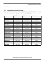
Communication Interface Settings: . . . . . . . . . . . . . . . . . . . . . . . . . 49
Chapter 14
Hello World QSPI Demo
14.1
Overview . . . . . . . . . . . . . . . . . . . . . . . . . . . . . . . . . . . . . . . . 51
14.2
Supported Platforms . . . . . . . . . . . . . . . . . . . . . . . . . . . . . . . . . . 51
14.3
14.3.1
14.3.2
System Requirement . . . . . . . . . . . . . . . . . . . . . . . . . . . . . . . . . . 51
Hardware requirements . . . . . . . . . . . . . . . . . . . . . . . . . . . . . . . 51
Software requirements . . . . . . . . . . . . . . . . . . . . . . . . . . . . . . . . 51
14.4
14.4.1
14.4.2
14.4.3
Getting Started . . . .
Hardware settings .
Prepare the example
Run the example . .
.
.
.
.
.
.
.
.
.
.
.
.
.
.
.
.
.
.
.
.
.
.
.
.
.
.
.
.
.
.
.
.
.
.
.
.
.
.
.
.
.
.
.
.
.
.
.
.
.
.
.
.
.
.
.
.
.
.
.
.
.
.
.
.
.
.
.
.
.
.
.
.
.
.
.
.
.
.
.
.
.
.
.
.
.
.
.
.
.
.
.
.
.
.
.
.
.
.
.
.
.
.
.
.
.
.
.
.
.
.
.
.
.
.
.
.
.
.
.
.
.
.
.
.
.
.
.
.
.
.
.
.
52
52
52
53
Chapter 15
Hardware Timer Demo
15.1
Overview . . . . . . . . . . . . . . . . . . . . . . . . . . . . . . . . . . . . . . . . 55
15.2
Supported Platforms . . . . . . . . . . . . . . . . . . . . . . . . . . . . . . . . . . 55
15.3
15.3.1
15.3.2
System Requirement . . . . . . . . . . . . . . . . . . . . . . . . . . . . . . . . . . 56
Hardware requirements . . . . . . . . . . . . . . . . . . . . . . . . . . . . . . . 56
Software requirements . . . . . . . . . . . . . . . . . . . . . . . . . . . . . . . . 56
15.4
15.4.1
15.4.2
Getting Started . . . . . . . . . . . . . . . . . . . . . . . . . . . . . . . . . . . . . 56
Prepare the Demo . . . . . . . . . . . . . . . . . . . . . . . . . . . . . . . . . . 56
Run the demo . . . . . . . . . . . . . . . . . . . . . . . . . . . . . . . . . . . . 56
15.5
15.5.1
15.5.2
15.5.3
15.5.4
Customization Options . . . . . . . . . . . . . . . .
Configure the Hardware Timer Used . . . . . . . .
Configure which clock is used by the hardware timer
Configure which instance of the module is used . .
Hardware Timer Period . . . . . . . . . . . . . . .
.
.
.
.
.
.
.
.
.
.
.
.
.
.
.
.
.
.
.
.
.
.
.
.
.
.
.
.
.
.
.
.
.
.
.
.
.
.
.
.
.
.
.
.
.
.
.
.
.
.
.
.
.
.
.
.
.
.
.
.
.
.
.
.
.
.
.
.
.
.
.
.
.
.
.
.
.
.
.
.
57
57
57
57
57
Kinetis SDK v.1.3 Demo Applications User’s Guide
viii
Freescale Semiconductor
Section number
Title
Page
Chapter 16
I2C Communication Demo
16.1
Overview . . . . . . . . . . . . . . . . . . . . . . . . . . . . . . . . . . . . . . . . 59
16.2
Supported Platforms . . . . . . . . . . . . . . . . . . . . . . . . . . . . . . . . . . 59
16.3
16.3.1
16.3.2
System Requirement . . . . . . . . . . . . . . . . . . . . . . . . . . . . . . . . . . 60
Hardware requirements . . . . . . . . . . . . . . . . . . . . . . . . . . . . . . . 60
Software requirements . . . . . . . . . . . . . . . . . . . . . . . . . . . . . . . . 60
16.4
16.4.1
16.4.2
16.4.3
Getting Started . . . . . .
Hardware configuration
Terminal configuration .
Run the demo . . . . .
.
.
.
.
.
.
.
.
.
.
.
.
.
.
.
.
.
.
.
.
.
.
.
.
.
.
.
.
.
.
.
.
.
.
.
.
.
.
.
.
.
.
.
.
.
.
.
.
.
.
.
.
.
.
.
.
.
.
.
.
.
.
.
.
.
.
.
.
.
.
.
.
.
.
.
.
.
.
.
.
.
.
.
.
.
.
.
.
.
.
.
.
.
.
.
.
.
.
.
.
.
.
.
.
.
.
.
.
.
.
.
.
.
.
.
.
.
.
.
.
.
.
.
.
60
60
67
67
Chapter 17
I2C Demo with RTOS
17.1
Overview . . . . . . . . . . . . . . . . . . . . . . . . . . . . . . . . . . . . . . . . 69
17.2
Supported RTOS . . . . . . . . . . . . . . . . . . . . . . . . . . . . . . . . . . . . 69
17.3
Supported Platforms . . . . . . . . . . . . . . . . . . . . . . . . . . . . . . . . . . 69
17.4
17.4.1
17.4.2
System Requirement . . . . . . . . . . . . . . . . . . . . . . . . . . . . . . . . . . 71
Hardware requirements . . . . . . . . . . . . . . . . . . . . . . . . . . . . . . . 71
Software requirements . . . . . . . . . . . . . . . . . . . . . . . . . . . . . . . . 71
17.5
17.5.1
17.5.2
17.5.3
Getting Started . . . . . . . . . . . .
Build with different RTOS support
Hardware configuration . . . . . .
Prepare the Demo . . . . . . . . .
17.6
Run the demo . . . . . . . . . . . . . . . . . . . . . . . . . . . . . . . . . . . . . 83
.
.
.
.
.
.
.
.
.
.
.
.
.
.
.
.
.
.
.
.
.
.
.
.
.
.
.
.
.
.
.
.
.
.
.
.
.
.
.
.
.
.
.
.
.
.
.
.
.
.
.
.
.
.
.
.
.
.
.
.
.
.
.
.
.
.
.
.
.
.
.
.
.
.
.
.
.
.
.
.
.
.
.
.
.
.
.
.
.
.
.
.
.
.
.
.
.
.
.
.
71
71
72
83
Chapter 18
iRTC Comp 1 Hz Demo
18.1
Overview . . . . . . . . . . . . . . . . . . . . . . . . . . . . . . . . . . . . . . . . 85
18.2
Supported Platforms . . . . . . . . . . . . . . . . . . . . . . . . . . . . . . . . . . 85
Kinetis SDK v.1.3 Demo Applications User’s Guide
Freescale Semiconductor
ix
Section number
Title
Page
18.3
18.3.1
System Requirement . . . . . . . . . . . . . . . . . . . . . . . . . . . . . . . . . . 85
Hardware requirements . . . . . . . . . . . . . . . . . . . . . . . . . . . . . . . 85
18.4
18.4.1
18.4.2
Getting Started . . . . . . . . . . . . . . . . . . . . . . . . . . . . . . . . . . . . . 85
Hardware Settings . . . . . . . . . . . . . . . . . . . . . . . . . . . . . . . . . . 85
Prepare the Demo . . . . . . . . . . . . . . . . . . . . . . . . . . . . . . . . . . 86
18.5
Run the demo . . . . . . . . . . . . . . . . . . . . . . . . . . . . . . . . . . . . . 86
Chapter 19
HTTP Server Demo on lwIP TCP/IP Stack
19.1
Overview . . . . . . . . . . . . . . . . . . . . . . . . . . . . . . . . . . . . . . . . 87
19.2
Supported RTOS . . . . . . . . . . . . . . . . . . . . . . . . . . . . . . . . . . . . 87
19.3
Supported Hardware . . . . . . . . . . . . . . . . . . . . . . . . . . . . . . . . . 87
19.4
19.4.1
19.4.2
System Requirement . . . . . . . . . . . . . . . . . . . . . . . . . . . . . . . . . . 87
Hardware requirements . . . . . . . . . . . . . . . . . . . . . . . . . . . . . . . 87
Software requirements . . . . . . . . . . . . . . . . . . . . . . . . . . . . . . . . 88
19.5
19.5.1
19.5.2
19.5.3
Getting Started . . . . . .
Prepare the Demo . . .
Network Configuration
Run the demo . . . . .
.
.
.
.
.
.
.
.
.
.
.
.
.
.
.
.
.
.
.
.
.
.
.
.
.
.
.
.
.
.
.
.
.
.
.
.
.
.
.
.
.
.
.
.
.
.
.
.
.
.
.
.
.
.
.
.
.
.
.
.
.
.
.
.
.
.
.
.
.
.
.
.
.
.
.
.
.
.
.
.
.
.
.
.
.
.
.
.
.
.
.
.
.
.
.
.
.
.
.
.
.
.
.
.
.
.
.
.
.
.
.
.
.
.
.
.
.
.
.
.
.
.
.
.
88
88
88
88
Chapter 20
Ping Demo on lwIP TCP/IP Stack
20.1
Overview . . . . . . . . . . . . . . . . . . . . . . . . . . . . . . . . . . . . . . . . 91
20.2
Supported RTOS . . . . . . . . . . . . . . . . . . . . . . . . . . . . . . . . . . . . 91
20.3
Supported Hardware . . . . . . . . . . . . . . . . . . . . . . . . . . . . . . . . . 91
20.4
20.4.1
20.4.2
System Requirement . . . . . . . . . . . . . . . . . . . . . . . . . . . . . . . . . . 91
Hardware requirements . . . . . . . . . . . . . . . . . . . . . . . . . . . . . . . 91
Software requirements . . . . . . . . . . . . . . . . . . . . . . . . . . . . . . . . 92
20.5
20.5.1
20.5.2
Getting Started . . . . . . . . . . . . . . . . . . . . . . . . . . . . . . . . . . . . . 92
Prepare the Demo . . . . . . . . . . . . . . . . . . . . . . . . . . . . . . . . . . 92
Network Configuration . . . . . . . . . . . . . . . . . . . . . . . . . . . . . . . 92
Kinetis SDK v.1.3 Demo Applications User’s Guide
x
Freescale Semiconductor
Section number
20.6
Title
Page
Run the demo . . . . . . . . . . . . . . . . . . . . . . . . . . . . . . . . . . . . . 92
Chapter 21
TCP Echo Demo on lwIP TCP/IP Stack
21.1
Overview . . . . . . . . . . . . . . . . . . . . . . . . . . . . . . . . . . . . . . . . 93
21.2
Supported RTOS . . . . . . . . . . . . . . . . . . . . . . . . . . . . . . . . . . . . 93
21.3
Supported Hardware . . . . . . . . . . . . . . . . . . . . . . . . . . . . . . . . . 93
21.4
21.4.1
21.4.2
System Requirement . . . . . . . . . . . . . . . . . . . . . . . . . . . . . . . . . . 93
Hardware requirements . . . . . . . . . . . . . . . . . . . . . . . . . . . . . . . 93
Software requirements . . . . . . . . . . . . . . . . . . . . . . . . . . . . . . . . 94
21.5
21.5.1
21.5.2
Getting Started . . . . . . . . . . . . . . . . . . . . . . . . . . . . . . . . . . . . . 94
Prepare the Demo . . . . . . . . . . . . . . . . . . . . . . . . . . . . . . . . . . 94
Network Configuration . . . . . . . . . . . . . . . . . . . . . . . . . . . . . . . 94
21.6
Run the demo . . . . . . . . . . . . . . . . . . . . . . . . . . . . . . . . . . . . . 94
Chapter 22
UDP Echo Demo on lwIP TCP/IP Stack
22.1
Overview . . . . . . . . . . . . . . . . . . . . . . . . . . . . . . . . . . . . . . . . 97
22.2
Supported RTOS . . . . . . . . . . . . . . . . . . . . . . . . . . . . . . . . . . . . 97
22.3
Supported Hardware . . . . . . . . . . . . . . . . . . . . . . . . . . . . . . . . . 97
22.4
22.4.1
22.4.2
System Requirement . . . . . . . . . . . . . . . . . . . . . . . . . . . . . . . . . . 97
Hardware requirements . . . . . . . . . . . . . . . . . . . . . . . . . . . . . . . 97
Software requirements . . . . . . . . . . . . . . . . . . . . . . . . . . . . . . . . 98
22.5
22.5.1
22.5.2
Getting Started . . . . . . . . . . . . . . . . . . . . . . . . . . . . . . . . . . . . . 98
Prepare the Demo . . . . . . . . . . . . . . . . . . . . . . . . . . . . . . . . . . 98
Network Configuration . . . . . . . . . . . . . . . . . . . . . . . . . . . . . . . 98
22.6
Run the demo . . . . . . . . . . . . . . . . . . . . . . . . . . . . . . . . . . . . . 98
Kinetis SDK v.1.3 Demo Applications User’s Guide
Freescale Semiconductor
xi
Section number
Title
Page
Chapter 23
MMAU Filter Demo
23.1
Overview . . . . . . . . . . . . . . . . . . . . . . . . . . . . . . . . . . . . . . . . 101
23.2
Supported Platforms . . . . . . . . . . . . . . . . . . . . . . . . . . . . . . . . . . 101
23.3
23.3.1
System Requirement . . . . . . . . . . . . . . . . . . . . . . . . . . . . . . . . . . 101
Hardware requirements . . . . . . . . . . . . . . . . . . . . . . . . . . . . . . . 101
23.4
23.4.1
23.4.2
23.4.3
Getting Started . . . .
Hardware settings .
Prepare the example
Run the example . .
.
.
.
.
.
.
.
.
.
.
.
.
.
.
.
.
.
.
.
.
.
.
.
.
.
.
.
.
.
.
.
.
.
.
.
.
.
.
.
.
.
.
.
.
.
.
.
.
.
.
.
.
.
.
.
.
.
.
.
.
.
.
.
.
.
.
.
.
.
.
.
.
.
.
.
.
.
.
.
.
.
.
.
.
.
.
.
.
.
.
.
.
.
.
.
.
.
.
.
.
.
.
.
.
.
.
.
.
.
.
.
.
.
.
.
.
.
.
.
.
.
.
.
.
.
.
.
.
.
.
.
.
101
101
101
102
Chapter 24
MMDVSQ Demo
24.1
Overview . . . . . . . . . . . . . . . . . . . . . . . . . . . . . . . . . . . . . . . . 105
24.2
Supported Platforms . . . . . . . . . . . . . . . . . . . . . . . . . . . . . . . . . . 105
24.3
24.3.1
24.3.2
System Requirement . . . . . . . . . . . . . . . . . . . . . . . . . . . . . . . . . . 105
Hardware requirements . . . . . . . . . . . . . . . . . . . . . . . . . . . . . . . 105
Software requirements . . . . . . . . . . . . . . . . . . . . . . . . . . . . . . . . 105
24.4
24.4.1
Getting Started . . . . . . . . . . . . . . . . . . . . . . . . . . . . . . . . . . . . . 105
Prepare the Demo . . . . . . . . . . . . . . . . . . . . . . . . . . . . . . . . . . 105
24.5
Run the demo . . . . . . . . . . . . . . . . . . . . . . . . . . . . . . . . . . . . . 106
Chapter 25
Power Manager HAL Demo
25.1
Overview . . . . . . . . . . . . . . . . . . . . . . . . . . . . . . . . . . . . . . . . 107
25.2
Supported Hardware . . . . . . . . . . . . . . . . . . . . . . . . . . . . . . . . . 107
25.3
25.3.1
25.3.2
System Requirement . . . . . . . . . . . . . . . . . . . . . . . . . . . . . . . . . . 108
Hardware requirements . . . . . . . . . . . . . . . . . . . . . . . . . . . . . . . 108
Software requirements . . . . . . . . . . . . . . . . . . . . . . . . . . . . . . . . 108
25.4
Getting Started . . . . . . . . . . . . . . . . . . . . . . . . . . . . . . . . . . . . . 108
Kinetis SDK v.1.3 Demo Applications User’s Guide
xii
Freescale Semiconductor
Section number
25.4.1
25.4.2
25.4.3
25.4.4
Title
Hardware Settings . . . . . . . . . . . . .
Prepare the Demo . . . . . . . . . . . . .
Run the demo . . . . . . . . . . . . . . .
Supported Low Power Modes By Platform
Page
.
.
.
.
.
.
.
.
.
.
.
.
.
.
.
.
.
.
.
.
.
.
.
.
.
.
.
.
.
.
.
.
.
.
.
.
.
.
.
.
.
.
.
.
.
.
.
.
.
.
.
.
.
.
.
.
.
.
.
.
.
.
.
.
.
.
.
.
.
.
.
.
.
.
.
.
.
.
.
.
.
.
.
.
108
108
108
110
Chapter 26
Power Manager RTOS Demo
26.1
Overview . . . . . . . . . . . . . . . . . . . . . . . . . . . . . . . . . . . . . . . . 113
26.2
Supported RTOS . . . . . . . . . . . . . . . . . . . . . . . . . . . . . . . . . . . . 113
26.3
Supported Hardware . . . . . . . . . . . . . . . . . . . . . . . . . . . . . . . . . 113
26.4
26.4.1
26.4.2
System Requirements . . . . . . . . . . . . . . . . . . . . . . . . . . . . . . . . . 114
Hardware requirements . . . . . . . . . . . . . . . . . . . . . . . . . . . . . . . 114
Software requirements . . . . . . . . . . . . . . . . . . . . . . . . . . . . . . . . 114
26.5
26.5.1
26.5.2
26.5.3
26.5.4
Getting Started . . . . . . . . . . . . . . . .
Hardware Settings . . . . . . . . . . . . .
Prepare the Demo . . . . . . . . . . . . .
Run the demo . . . . . . . . . . . . . . .
Supported Low Power Modes By Platform
.
.
.
.
.
.
.
.
.
.
.
.
.
.
.
.
.
.
.
.
.
.
.
.
.
.
.
.
.
.
.
.
.
.
.
.
.
.
.
.
.
.
.
.
.
.
.
.
.
.
.
.
.
.
.
.
.
.
.
.
.
.
.
.
.
.
.
.
.
.
.
.
.
.
.
.
.
.
.
.
.
.
.
.
.
.
.
.
.
.
.
.
.
.
.
.
.
.
.
.
.
.
.
.
.
115
115
115
115
116
Chapter 27
RTC Function Demo
27.1
Overview . . . . . . . . . . . . . . . . . . . . . . . . . . . . . . . . . . . . . . . . 119
27.2
Supported Hardware . . . . . . . . . . . . . . . . . . . . . . . . . . . . . . . . . 119
27.3
27.3.1
27.3.2
System Requirement . . . . . . . . . . . . . . . . . . . . . . . . . . . . . . . . . . 120
Hardware requirements . . . . . . . . . . . . . . . . . . . . . . . . . . . . . . . 120
Software requirements . . . . . . . . . . . . . . . . . . . . . . . . . . . . . . . . 120
27.4
27.4.1
Getting Started . . . . . . . . . . . . . . . . . . . . . . . . . . . . . . . . . . . . . 120
Prepare the Demo . . . . . . . . . . . . . . . . . . . . . . . . . . . . . . . . . . 120
27.5
Run the demo . . . . . . . . . . . . . . . . . . . . . . . . . . . . . . . . . . . . . 121
Kinetis SDK v.1.3 Demo Applications User’s Guide
Freescale Semiconductor
xiii
Section number
Title
Page
Chapter 28
SAI Demo
28.1
Overview . . . . . . . . . . . . . . . . . . . . . . . . . . . . . . . . . . . . . . . . 123
28.2
Supported Hardware . . . . . . . . . . . . . . . . . . . . . . . . . . . . . . . . . 123
28.3
28.3.1
28.3.2
System Requirement . . . . . . . . . . . . . . . . . . . . . . . . . . . . . . . . . . 123
Hardware requirements . . . . . . . . . . . . . . . . . . . . . . . . . . . . . . . 123
Software requirements . . . . . . . . . . . . . . . . . . . . . . . . . . . . . . . . 123
28.4
28.4.1
28.4.2
28.4.3
Getting Started . . . .
GCC Compiler notes
Hardware Settings .
Prepare the Demo .
28.5
Run the demo . . . . . . . . . . . . . . . . . . . . . . . . . . . . . . . . . . . . . 124
28.6
Key Functions . . . . . . . . . . . . . . . . . . . . . . . . . . . . . . . . . . . . . 127
.
.
.
.
.
.
.
.
.
.
.
.
.
.
.
.
.
.
.
.
.
.
.
.
.
.
.
.
.
.
.
.
.
.
.
.
.
.
.
.
.
.
.
.
.
.
.
.
.
.
.
.
.
.
.
.
.
.
.
.
.
.
.
.
.
.
.
.
.
.
.
.
.
.
.
.
.
.
.
.
.
.
.
.
.
.
.
.
.
.
.
.
.
.
.
.
.
.
.
.
.
.
.
.
.
.
.
.
.
.
.
.
.
.
.
.
.
.
.
.
.
.
.
.
.
.
.
.
.
.
.
.
124
124
124
124
Chapter 29
SLCD basic testing and an Guess Number game
29.1
Overview . . . . . . . . . . . . . . . . . . . . . . . . . . . . . . . . . . . . . . . . 131
29.2
Supported Platforms . . . . . . . . . . . . . . . . . . . . . . . . . . . . . . . . . . 131
29.3
29.3.1
29.3.2
Getting Started . . . . . . . . . . . . . . . . . . . . . . . . . . . . . . . . . . . . . 131
Hardware Settings . . . . . . . . . . . . . . . . . . . . . . . . . . . . . . . . . . 131
Prepare the Demo . . . . . . . . . . . . . . . . . . . . . . . . . . . . . . . . . . 131
29.4
Run the demo . . . . . . . . . . . . . . . . . . . . . . . . . . . . . . . . . . . . . 132
29.5
Communication Interface Settings: . . . . . . . . . . . . . . . . . . . . . . . . . 132
Chapter 30
SLCD Low Power Demo
30.1
Overview . . . . . . . . . . . . . . . . . . . . . . . . . . . . . . . . . . . . . . . . 133
30.2
Supported Hardware . . . . . . . . . . . . . . . . . . . . . . . . . . . . . . . . . 133
30.3
System Requirement . . . . . . . . . . . . . . . . . . . . . . . . . . . . . . . . . . 133
Kinetis SDK v.1.3 Demo Applications User’s Guide
xiv
Freescale Semiconductor
Section number
Title
Page
30.3.1
Hardware requirements . . . . . . . . . . . . . . . . . . . . . . . . . . . . . . . 133
30.4
30.4.1
Getting Started . . . . . . . . . . . . . . . . . . . . . . . . . . . . . . . . . . . . . 133
Prepare the Demo . . . . . . . . . . . . . . . . . . . . . . . . . . . . . . . . . . 133
30.5
Run the demo . . . . . . . . . . . . . . . . . . . . . . . . . . . . . . . . . . . . . 134
Chapter 31
Thermistor Lab Demo
31.1
Overview . . . . . . . . . . . . . . . . . . . . . . . . . . . . . . . . . . . . . . . . 135
31.2
Supported Hardware . . . . . . . . . . . . . . . . . . . . . . . . . . . . . . . . . 135
31.3
31.3.1
31.3.2
System Requirement . . . . . . . . . . . . . . . . . . . . . . . . . . . . . . . . . . 135
Hardware requirements . . . . . . . . . . . . . . . . . . . . . . . . . . . . . . . 135
Software requirements . . . . . . . . . . . . . . . . . . . . . . . . . . . . . . . . 135
31.4
31.4.1
31.4.2
31.4.2.1
Getting Started . . . . . . . . . . . . . . .
Prepare the Demo . . . . . . . . . . . .
Demo Code Overview . . . . . . . . . .
ADC Differential Mode of Operation
.
.
.
.
.
.
.
.
.
.
.
.
.
.
.
.
.
.
.
.
.
.
.
.
.
.
.
.
.
.
.
.
.
.
.
.
.
.
.
.
.
.
.
.
.
.
.
.
.
.
.
.
.
.
.
.
.
.
.
.
.
.
.
.
.
.
.
.
.
.
.
.
.
.
.
.
.
.
.
.
.
.
.
.
.
.
.
.
135
135
136
137
Chapter 32
Heating, Ventilating, and Air Conditioning on lwIP TCP/IP
Stack
32.1
Overview . . . . . . . . . . . . . . . . . . . . . . . . . . . . . . . . . . . . . . . . 139
32.2
Supported RTOS . . . . . . . . . . . . . . . . . . . . . . . . . . . . . . . . . . . . 139
32.3
Supported Hardware . . . . . . . . . . . . . . . . . . . . . . . . . . . . . . . . . 139
32.4
32.4.1
32.4.2
32.4.3
System Requirement . . .
Hardware requirements
Software requirements .
Software requirements .
.
.
.
.
.
.
.
.
.
.
.
.
.
.
.
.
.
.
.
.
.
.
.
.
.
.
.
.
.
.
.
.
.
.
.
.
.
.
.
.
.
.
.
.
.
.
.
.
.
.
.
.
.
.
.
.
.
.
.
.
.
.
.
.
.
.
.
.
.
.
.
.
.
.
.
.
.
.
.
.
.
.
.
.
.
.
.
.
.
.
.
.
.
.
.
.
.
.
.
.
.
.
.
.
.
.
.
.
.
.
.
.
.
.
.
.
.
.
.
.
.
.
.
.
139
139
140
140
32.5
32.5.1
32.5.2
32.5.3
Getting Started . . . . . .
Prepare the Demo . . .
Network Configuration
Run the demo . . . . .
.
.
.
.
.
.
.
.
.
.
.
.
.
.
.
.
.
.
.
.
.
.
.
.
.
.
.
.
.
.
.
.
.
.
.
.
.
.
.
.
.
.
.
.
.
.
.
.
.
.
.
.
.
.
.
.
.
.
.
.
.
.
.
.
.
.
.
.
.
.
.
.
.
.
.
.
.
.
.
.
.
.
.
.
.
.
.
.
.
.
.
.
.
.
.
.
.
.
.
.
.
.
.
.
.
.
.
.
.
.
.
.
.
.
.
.
.
.
.
.
.
.
.
.
140
140
140
140
Kinetis SDK v.1.3 Demo Applications User’s Guide
Freescale Semiconductor
xv
Section number
Title
Page
Chapter 33
ADC16 Example
33.1
Overview . . . . . . . . . . . . . . . . . . . . . . . . . . . . . . . . . . . . . . . . 143
33.2
Supported Platforms . . . . . . . . . . . . . . . . . . . . . . . . . . . . . . . . . . 143
33.3
33.3.1
33.3.2
System Requirement . . . . . . . . . . . . . . . . . . . . . . . . . . . . . . . . . . 144
Hardware requirements . . . . . . . . . . . . . . . . . . . . . . . . . . . . . . . 144
Software requirements . . . . . . . . . . . . . . . . . . . . . . . . . . . . . . . . 144
33.4
33.4.1
33.4.2
33.4.3
Getting Started . . . .
Hardware settings .
Prepare the example
Run the example . .
.
.
.
.
.
.
.
.
.
.
.
.
.
.
.
.
.
.
.
.
.
.
.
.
.
.
.
.
.
.
.
.
.
.
.
.
.
.
.
.
.
.
.
.
.
.
.
.
.
.
.
.
.
.
.
.
.
.
.
.
.
.
.
.
.
.
.
.
.
.
.
.
.
.
.
.
.
.
.
.
.
.
.
.
.
.
.
.
.
.
.
.
.
.
.
.
.
.
.
.
.
.
.
.
.
.
.
.
.
.
.
.
.
.
.
.
.
.
.
.
.
.
.
.
.
.
.
.
.
.
.
.
144
144
144
144
Chapter 34
AFE Example
34.1
Overview . . . . . . . . . . . . . . . . . . . . . . . . . . . . . . . . . . . . . . . . 147
34.2
Supported Platforms . . . . . . . . . . . . . . . . . . . . . . . . . . . . . . . . . . 147
34.3
34.3.1
System Requirement . . . . . . . . . . . . . . . . . . . . . . . . . . . . . . . . . . 147
Hardware requirements . . . . . . . . . . . . . . . . . . . . . . . . . . . . . . . 147
34.4
34.4.1
34.4.2
34.4.3
Getting Started . . . .
Hardware settings .
Prepare the example
Run the example . .
.
.
.
.
.
.
.
.
.
.
.
.
.
.
.
.
.
.
.
.
.
.
.
.
.
.
.
.
.
.
.
.
.
.
.
.
.
.
.
.
.
.
.
.
.
.
.
.
.
.
.
.
.
.
.
.
.
.
.
.
.
.
.
.
.
.
.
.
.
.
.
.
.
.
.
.
.
.
.
.
.
.
.
.
.
.
.
.
.
.
.
.
.
.
.
.
.
.
.
.
.
.
.
.
.
.
.
.
.
.
.
.
.
.
.
.
.
.
.
.
.
.
.
.
.
.
.
.
.
.
.
.
147
147
148
148
Chapter 35
CMP Example
35.1
Overview . . . . . . . . . . . . . . . . . . . . . . . . . . . . . . . . . . . . . . . . 149
35.2
Supported Platforms . . . . . . . . . . . . . . . . . . . . . . . . . . . . . . . . . . 149
35.3
35.3.1
35.3.2
System Requirement . . . . . . . . . . . . . . . . . . . . . . . . . . . . . . . . . . 149
Hardware requirements . . . . . . . . . . . . . . . . . . . . . . . . . . . . . . . 149
Software requirements . . . . . . . . . . . . . . . . . . . . . . . . . . . . . . . . 149
35.4
Getting Started . . . . . . . . . . . . . . . . . . . . . . . . . . . . . . . . . . . . . 150
Kinetis SDK v.1.3 Demo Applications User’s Guide
xvi
Freescale Semiconductor
Section number
35.4.1
35.4.2
35.4.3
35.4.4
Title
Hardware configuration
Hardware settings . . .
Prepare the example . .
Run the example . . . .
.
.
.
.
.
.
.
.
.
.
.
.
.
.
.
.
.
.
.
.
.
.
.
.
.
.
.
.
Page
.
.
.
.
.
.
.
.
.
.
.
.
.
.
.
.
.
.
.
.
.
.
.
.
.
.
.
.
.
.
.
.
.
.
.
.
.
.
.
.
.
.
.
.
.
.
.
.
.
.
.
.
.
.
.
.
.
.
.
.
.
.
.
.
.
.
.
.
.
.
.
.
.
.
.
.
.
.
.
.
.
.
.
.
.
.
.
.
.
.
.
.
.
.
.
.
150
150
150
150
Chapter 36
CMT Example
36.1
Overview . . . . . . . . . . . . . . . . . . . . . . . . . . . . . . . . . . . . . . . . 153
36.2
Supported Platforms . . . . . . . . . . . . . . . . . . . . . . . . . . . . . . . . . . 153
36.3
36.3.1
36.3.2
System Requirement . . . . . . . . . . . . . . . . . . . . . . . . . . . . . . . . . . 153
Hardware requirements . . . . . . . . . . . . . . . . . . . . . . . . . . . . . . . 153
Software requirements . . . . . . . . . . . . . . . . . . . . . . . . . . . . . . . . 153
36.4
36.4.1
36.4.2
36.4.3
Getting Started . . . .
Hardware settings .
Prepare the example
Run the example . .
.
.
.
.
.
.
.
.
.
.
.
.
.
.
.
.
.
.
.
.
.
.
.
.
.
.
.
.
.
.
.
.
.
.
.
.
.
.
.
.
.
.
.
.
.
.
.
.
.
.
.
.
.
.
.
.
.
.
.
.
.
.
.
.
.
.
.
.
.
.
.
.
.
.
.
.
.
.
.
.
.
.
.
.
.
.
.
.
.
.
.
.
.
.
.
.
.
.
.
.
.
.
.
.
.
.
.
.
.
.
.
.
.
.
.
.
.
.
.
.
.
.
.
.
.
.
.
.
.
.
.
.
153
153
154
154
Chapter 37
COP Example
37.1
Overview . . . . . . . . . . . . . . . . . . . . . . . . . . . . . . . . . . . . . . . . 155
37.2
Supported Platforms . . . . . . . . . . . . . . . . . . . . . . . . . . . . . . . . . . 155
37.3
37.3.1
37.3.2
System Requirement . . . . . . . . . . . . . . . . . . . . . . . . . . . . . . . . . . 155
Hardware requirements . . . . . . . . . . . . . . . . . . . . . . . . . . . . . . . 155
Software requirements . . . . . . . . . . . . . . . . . . . . . . . . . . . . . . . . 155
37.4
37.4.1
37.4.2
37.4.3
Getting Started . . . .
Hardware settings .
Prepare the example
Run the example . .
.
.
.
.
.
.
.
.
.
.
.
.
.
.
.
.
.
.
.
.
.
.
.
.
.
.
.
.
.
.
.
.
.
.
.
.
.
.
.
.
.
.
.
.
.
.
.
.
.
.
.
.
.
.
.
.
.
.
.
.
.
.
.
.
.
.
.
.
.
.
.
.
.
.
.
.
.
.
.
.
.
.
.
.
.
.
.
.
.
.
.
.
.
.
.
.
.
.
.
.
.
.
.
.
.
.
.
.
.
.
.
.
.
.
.
.
.
.
.
.
.
.
.
.
.
.
.
.
.
.
.
.
156
156
156
156
Chapter 38
DAC Example
38.1
Overview . . . . . . . . . . . . . . . . . . . . . . . . . . . . . . . . . . . . . . . . 157
Kinetis SDK v.1.3 Demo Applications User’s Guide
Freescale Semiconductor
xvii
Section number
Title
Page
38.2
Supported Platforms . . . . . . . . . . . . . . . . . . . . . . . . . . . . . . . . . . 157
38.3
38.3.1
38.3.2
System Requirement . . . . . . . . . . . . . . . . . . . . . . . . . . . . . . . . . . 157
Hardware requirements . . . . . . . . . . . . . . . . . . . . . . . . . . . . . . . 157
Software requirements . . . . . . . . . . . . . . . . . . . . . . . . . . . . . . . . 158
38.4
38.4.1
38.4.2
38.4.3
Getting Started . . . .
Hardware settings .
Prepare the example
Run the example . .
.
.
.
.
.
.
.
.
.
.
.
.
.
.
.
.
.
.
.
.
.
.
.
.
.
.
.
.
.
.
.
.
.
.
.
.
.
.
.
.
.
.
.
.
.
.
.
.
.
.
.
.
.
.
.
.
.
.
.
.
.
.
.
.
.
.
.
.
.
.
.
.
.
.
.
.
.
.
.
.
.
.
.
.
.
.
.
.
.
.
.
.
.
.
.
.
.
.
.
.
.
.
.
.
.
.
.
.
.
.
.
.
.
.
.
.
.
.
.
.
.
.
.
.
.
.
.
.
.
.
.
.
158
158
158
158
Chapter 39
DMA Example
39.1
Overview . . . . . . . . . . . . . . . . . . . . . . . . . . . . . . . . . . . . . . . . 159
39.2
Supported Platforms . . . . . . . . . . . . . . . . . . . . . . . . . . . . . . . . . . 159
39.3
39.3.1
39.3.2
System Requirement . . . . . . . . . . . . . . . . . . . . . . . . . . . . . . . . . . 159
Hardware requirements . . . . . . . . . . . . . . . . . . . . . . . . . . . . . . . 159
Software requirements . . . . . . . . . . . . . . . . . . . . . . . . . . . . . . . . 160
39.4
39.4.1
39.4.2
39.4.3
Getting Started . . . .
Hardware settings .
Prepare the example
Run the example . .
.
.
.
.
.
.
.
.
.
.
.
.
.
.
.
.
.
.
.
.
.
.
.
.
.
.
.
.
.
.
.
.
.
.
.
.
.
.
.
.
.
.
.
.
.
.
.
.
.
.
.
.
.
.
.
.
.
.
.
.
.
.
.
.
.
.
.
.
.
.
.
.
.
.
.
.
.
.
.
.
.
.
.
.
.
.
.
.
.
.
.
.
.
.
.
.
.
.
.
.
.
.
.
.
.
.
.
.
.
.
.
.
.
.
.
.
.
.
.
.
.
.
.
.
.
.
.
.
.
.
.
.
160
160
160
160
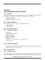
Chapter 40
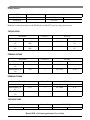
DSPI Example with other methods
40.1
Overview . . . . . . . . . . . . . . . . . . . . . . . . . . . . . . . . . . . . . . . . 163
40.2
Supported Platforms . . . . . . . . . . . . . . . . . . . . . . . . . . . . . . . . . . 163
40.3
40.3.1
40.3.2
System Requirement . . . . . . . . . . . . . . . . . . . . . . . . . . . . . . . . . . 164
Hardware requirements . . . . . . . . . . . . . . . . . . . . . . . . . . . . . . . 164
Software requirements . . . . . . . . . . . . . . . . . . . . . . . . . . . . . . . . 164
40.4
40.4.1
40.4.2
40.4.3
Getting Started . . . .
Hardware settings .
Prepare the example
Run the example . .
.
.
.
.
.
.
.
.
.
.
.
.
.
.
.
.
.
.
.
.
.
.
.
.
.
.
.
.
.
.
.
.
.
.
.
.
.
.
.
.
.
.
.
.
.
.
.
.
.
.
.
.
.
.
.
.
.
.
.
.
.
.
.
.
.
.
.
.
.
.
.
.
.
.
.
.
.
.
.
.
.
.
.
.
.
.
.
.
.
.
.
.
.
.
.
.
.
.
.
.
.
.
.
.
.
.
.
.
.
.
.
.
.
.
.
.
.
.
.
.
.
.
.
.
.
.
.
.
.
.
.
.
164
164
168
168
Kinetis SDK v.1.3 Demo Applications User’s Guide
xviii
Freescale Semiconductor
Section number
Title
Page
Chapter 41
EDMA Example
41.1
Overview . . . . . . . . . . . . . . . . . . . . . . . . . . . . . . . . . . . . . . . . 173
41.2
Supported Platforms . . . . . . . . . . . . . . . . . . . . . . . . . . . . . . . . . . 173
41.3
41.3.1
41.3.2
System Requirement . . . . . . . . . . . . . . . . . . . . . . . . . . . . . . . . . . 173
Hardware requirements . . . . . . . . . . . . . . . . . . . . . . . . . . . . . . . 173
Software requirements . . . . . . . . . . . . . . . . . . . . . . . . . . . . . . . . 174
41.4
41.4.1
41.4.2
41.4.3
Getting Started . . . .
Hardware settings .
Prepare the example
Run the example . .
.
.
.
.
.
.
.
.
.
.
.
.
.
.
.
.
.
.
.
.
.
.
.
.
.
.
.
.
.
.
.
.
.
.
.
.
.
.
.
.
.
.
.
.
.
.
.
.
.
.
.
.
.
.
.
.
.
.
.
.
.
.
.
.
.
.
.
.
.
.
.
.
.
.
.
.
.
.
.
.
.
.
.
.
.
.
.
.
.
.
.
.
.
.
.
.
.
.
.
.
.
.
.
.
.
.
.
.
.
.
.
.
.
.
.
.
.
.
.
.
.
.
.
.
.
.
.
.
.
.
.
.
174
174
174
174
Chapter 42
EWM Example
42.1
Overview . . . . . . . . . . . . . . . . . . . . . . . . . . . . . . . . . . . . . . . . 177
42.2
Supported Platforms . . . . . . . . . . . . . . . . . . . . . . . . . . . . . . . . . . 177
42.3
42.3.1
42.3.2
System Requirement . . . . . . . . . . . . . . . . . . . . . . . . . . . . . . . . . . 177
Hardware requirements . . . . . . . . . . . . . . . . . . . . . . . . . . . . . . . 177
Software requirements . . . . . . . . . . . . . . . . . . . . . . . . . . . . . . . . 178
42.4
42.4.1
42.4.2
42.4.3
Getting Started . . . .
Hardware settings .
Prepare the example
Run the example . .
.
.
.
.
.
.
.
.
.
.
.
.
.
.
.
.
.
.
.
.
.
.
.
.
.
.
.
.
.
.
.
.
.
.
.
.
.
.
.
.
.
.
.
.
.
.
.
.
.
.
.
.
.
.
.
.
.
.
.
.
.
.
.
.
.
.
.
.
.
.
.
.
.
.
.
.
.
.
.
.
.
.
.
.
.
.
.
.
.
.
.
.
.
.
.
.
.
.
.
.
.
.
.
.
.
.
.
.
.
.
.
.
.
.
.
.
.
.
.
.
.
.
.
.
.
.
.
.
.
.
.
.
178
178
178
178
Chapter 43
FLASH Example
43.1
Overview . . . . . . . . . . . . . . . . . . . . . . . . . . . . . . . . . . . . . . . . 179
43.2
Supported Platforms . . . . . . . . . . . . . . . . . . . . . . . . . . . . . . . . . . 179
43.3
43.3.1
43.3.2
System Requirement . . . . . . . . . . . . . . . . . . . . . . . . . . . . . . . . . . 180
Hardware requirements . . . . . . . . . . . . . . . . . . . . . . . . . . . . . . . 180
Software requirements . . . . . . . . . . . . . . . . . . . . . . . . . . . . . . . . 180
Kinetis SDK v.1.3 Demo Applications User’s Guide
Freescale Semiconductor
xix
Section number
43.4
43.4.1
43.4.2
43.4.3
Title
Getting Started . . . .
Hardware settings .
Prepare the example
Run the example . .
.
.
.
.
.
.
.
.
.
.
.
.
.
.
.
.
.
.
.
.
.
.
.
.
.
.
.
.
.
.
.
.
.
.
.
.
Page
.
.
.
.
.
.
.
.
.
.
.
.
.
.
.
.
.
.
.
.
.
.
.
.
.
.
.
.
.
.
.
.
.
.
.
.
.
.
.
.
.
.
.
.
.
.
.
.
.
.
.
.
.
.
.
.
.
.
.
.
.
.
.
.
.
.
.
.
.
.
.
.
.
.
.
.
.
.
.
.
.
.
.
.
.
.
.
.
.
.
.
.
.
.
.
.
180
180
180
181
Chapter 44
FlexCAN Example
44.1
Overview . . . . . . . . . . . . . . . . . . . . . . . . . . . . . . . . . . . . . . . . 183
44.2
Supported Platforms . . . . . . . . . . . . . . . . . . . . . . . . . . . . . . . . . . 183
44.3
44.3.1
44.3.2
System Requirement . . . . . . . . . . . . . . . . . . . . . . . . . . . . . . . . . . 183
Hardware requirements . . . . . . . . . . . . . . . . . . . . . . . . . . . . . . . 183
Software requirements . . . . . . . . . . . . . . . . . . . . . . . . . . . . . . . . 183
44.4
44.4.1
44.4.2
44.4.3
44.4.3.1
44.4.3.2
Getting Started . . . . .
Hardware settings . .
Prepare the example .
Run the example . . .
FlexCAN loopback
FlexCAN network
.
.
.
.
.
.
.
.
.
.
.
.
.
.
.
.
.
.
.
.
.
.
.
.
.
.
.
.
.
.
.
.
.
.
.
.
.
.
.
.
.
.
.
.
.
.
.
.
.
.
.
.
.
.
.
.
.
.
.
.
.
.
.
.
.
.
.
.
.
.
.
.
.
.
.
.
.
.
.
.
.
.
.
.
.
.
.
.
.
.
.
.
.
.
.
.
.
.
.
.
.
.
.
.
.
.
.
.
.
.
.
.
.
.
.
.
.
.
.
.
.
.
.
.
.
.
.
.
.
.
.
.
.
.
.
.
.
.
.
.
.
.
.
.
.
.
.
.
.
.
.
.
.
.
.
.
.
.
.
.
.
.
.
.
.
.
.
.
.
.
.
.
.
.
.
.
.
.
.
.
.
.
.
.
.
.
.
.
.
.
.
.
184
184
184
184
184
185
Chapter 45
FlexIO simulated I2C Example with other methods
45.1
Overview . . . . . . . . . . . . . . . . . . . . . . . . . . . . . . . . . . . . . . . . 187
45.2
Supported Platforms . . . . . . . . . . . . . . . . . . . . . . . . . . . . . . . . . . 187
45.3
45.3.1
45.3.2
System Requirement . . . . . . . . . . . . . . . . . . . . . . . . . . . . . . . . . . 187
Hardware requirements . . . . . . . . . . . . . . . . . . . . . . . . . . . . . . . 187
Software requirements . . . . . . . . . . . . . . . . . . . . . . . . . . . . . . . . 187
45.4
45.4.1
45.4.2
45.4.3
Getting Started . . . .
Hardware settings .
Prepare the example
Run the example . .
.
.
.
.
.
.
.
.
.
.
.
.
.
.
.
.
.
.
.
.
.
.
.
.
.
.
.
.
.
.
.
.
.
.
.
.
.
.
.
.
.
.
.
.
.
.
.
.
.
.
.
.
.
.
.
.
.
.
.
.
.
.
.
.
.
.
.
.
.
.
.
.
.
.
.
.
.
.
.
.
.
.
.
.
.
.
.
.
.
.
.
.
.
.
.
.
.
.
.
.
.
.
.
.
.
.
.
.
.
.
.
.
.
.
.
.
.
.
.
.
.
.
.
.
.
.
.
.
.
.
.
.
187
187
189
189
Kinetis SDK v.1.3 Demo Applications User’s Guide
xx
Freescale Semiconductor
Section number
Title
Page
Chapter 46
Flexio I2S Example with other methods
46.1
Overview . . . . . . . . . . . . . . . . . . . . . . . . . . . . . . . . . . . . . . . . 191
46.2
Supported Platforms . . . . . . . . . . . . . . . . . . . . . . . . . . . . . . . . . . 191
46.3
46.3.1
46.3.2
System Requirement . . . . . . . . . . . . . . . . . . . . . . . . . . . . . . . . . . 191
Hardware requirements . . . . . . . . . . . . . . . . . . . . . . . . . . . . . . . 191
Software requirements . . . . . . . . . . . . . . . . . . . . . . . . . . . . . . . . 191
46.4
46.4.1
46.4.2
46.4.3
Getting Started . . . .
Hardware settings .
Prepare the example
Run the example . .
.
.
.
.
.
.
.
.
.
.
.
.
.
.
.
.
.
.
.
.
.
.
.
.
.
.
.
.
.
.
.
.
.
.
.
.
.
.
.
.
.
.
.
.
.
.
.
.
.
.
.
.
.
.
.
.
.
.
.
.
.
.
.
.
.
.
.
.
.
.
.
.
.
.
.
.
.
.
.
.
.
.
.
.
.
.
.
.
.
.
.
.
.
.
.
.
.
.
.
.
.
.
.
.
.
.
.
.
.
.
.
.
.
.
.
.
.
.
.
.
.
.
.
.
.
.
.
.
.
.
.
.
191
191
193
193
Chapter 47
FlexIO IRDA Example
47.1
Overview . . . . . . . . . . . . . . . . . . . . . . . . . . . . . . . . . . . . . . . . 195
47.2
Supported Platforms . . . . . . . . . . . . . . . . . . . . . . . . . . . . . . . . . . 195
47.3
47.3.1
System Requirement . . . . . . . . . . . . . . . . . . . . . . . . . . . . . . . . . . 195
Hardware requirements . . . . . . . . . . . . . . . . . . . . . . . . . . . . . . . 195
47.4
47.4.1
47.4.2
Getting Started . . . . . . . . . . . . . . . . . . . . . . . . . . . . . . . . . . . . . 195
Hardware Settings . . . . . . . . . . . . . . . . . . . . . . . . . . . . . . . . . . 195
Prepare the Demo . . . . . . . . . . . . . . . . . . . . . . . . . . . . . . . . . . 196
47.5
47.5.1
Run the demo . . . . . . . . . . . . . . . . . . . . . . . . . . . . . . . . . . . . . 197
Customization Options . . . . . . . . . . . . . . . . . . . . . . . . . . . . . . . . 197
Chapter 48
FlexIO-simulated SPI Example with other methods
48.1
Overview . . . . . . . . . . . . . . . . . . . . . . . . . . . . . . . . . . . . . . . . 199
48.2
Supported Platforms . . . . . . . . . . . . . . . . . . . . . . . . . . . . . . . . . . 199
48.3
48.3.1
48.3.2
System Requirement . . . . . . . . . . . . . . . . . . . . . . . . . . . . . . . . . . 199
Hardware requirements . . . . . . . . . . . . . . . . . . . . . . . . . . . . . . . 199
Software requirements . . . . . . . . . . . . . . . . . . . . . . . . . . . . . . . . 199
Kinetis SDK v.1.3 Demo Applications User’s Guide
Freescale Semiconductor
xxi
Section number
48.4
48.4.1
48.4.2
48.4.3
Title
Getting Started . . . .
Hardware settings .
Prepare the example
Run the example . .
.
.
.
.
.
.
.
.
.
.
.
.
.
.
.
.
.
.
.
.
.
.
.
.
.
.
.
.
.
.
.
.
.
.
.
.
Page
.
.
.
.
.
.
.
.
.
.
.
.
.
.
.
.
.
.
.
.
.
.
.
.
.
.
.
.
.
.
.
.
.
.
.
.
.
.
.
.
.
.
.
.
.
.
.
.
.
.
.
.
.
.
.
.
.
.
.
.
.
.
.
.
.
.
.
.
.
.
.
.
.
.
.
.
.
.
.
.
.
.
.
.
.
.
.
.
.
.
.
.
.
.
.
.
200
200
202
202
Chapter 49
FlexIO-simulated UART Example with other methods
49.1
Overview . . . . . . . . . . . . . . . . . . . . . . . . . . . . . . . . . . . . . . . . 205
49.2
Supported Platforms . . . . . . . . . . . . . . . . . . . . . . . . . . . . . . . . . . 205
49.3
49.3.1
49.3.2
System Requirement . . . . . . . . . . . . . . . . . . . . . . . . . . . . . . . . . . 205
Hardware requirements . . . . . . . . . . . . . . . . . . . . . . . . . . . . . . . 205
Software requirements . . . . . . . . . . . . . . . . . . . . . . . . . . . . . . . . 205
49.4
49.4.1
49.4.2
49.4.3
49.4.3.1
49.4.3.2
Getting Started . . . . . . . . . . .
Hardware settings . . . . . . . .
Prepare the example . . . . . . .
Run the example . . . . . . . . .
FLEXIO_UART interrupt way
FLEXIO_UART interrupt way
.
.
.
.
.
.
.
.
.
.
.
.
.
.
.
.
.
.
.
.
.
.
.
.
.
.
.
.
.
.
.
.
.
.
.
.
.
.
.
.
.
.
.
.
.
.
.
.
.
.
.
.
.
.
.
.
.
.
.
.
.
.
.
.
.
.
.
.
.
.
.
.
.
.
.
.
.
.
.
.
.
.
.
.
.
.
.
.
.
.
.
.
.
.
.
.
.
.
.
.
.
.
.
.
.
.
.
.
.
.
.
.
.
.
.
.
.
.
.
.
.
.
.
.
.
.
.
.
.
.
.
.
.
.
.
.
.
.
.
.
.
.
.
.
.
.
.
.
.
.
.
.
.
.
.
.
206
206
207
207
207
208
Chapter 50
FTM Example
50.1
Overview . . . . . . . . . . . . . . . . . . . . . . . . . . . . . . . . . . . . . . . . 209
50.2
Supported Platforms . . . . . . . . . . . . . . . . . . . . . . . . . . . . . . . . . . 209
50.3
50.3.1
50.3.2
System Requirement . . . . . . . . . . . . . . . . . . . . . . . . . . . . . . . . . . 209
Hardware requirements . . . . . . . . . . . . . . . . . . . . . . . . . . . . . . . 209
Software requirements . . . . . . . . . . . . . . . . . . . . . . . . . . . . . . . . 210
50.4
50.4.1
50.4.2
50.4.3
Getting Started . . . .
Hardware settings .
Prepare the example
Run the example . .
.
.
.
.
.
.
.
.
.
.
.
.
.
.
.
.
.
.
.
.
.
.
.
.
.
.
.
.
.
.
.
.
.
.
.
.
.
.
.
.
.
.
.
.
.
.
.
.
.
.
.
.
.
.
.
.
.
.
.
.
.
.
.
.
.
.
.
.
.
.
.
.
.
.
.
.
.
.
.
.
.
.
.
.
.
.
.
.
.
.
.
.
.
.
.
.
.
.
.
.
.
.
.
.
.
.
.
.
.
.
.
.
.
.
.
.
.
.
.
.
.
.
.
.
.
.
.
.
.
.
.
.
210
210
210
210
Kinetis SDK v.1.3 Demo Applications User’s Guide
xxii
Freescale Semiconductor
Section number
Title
Page
Chapter 51
GPIO Example
51.1
Overview . . . . . . . . . . . . . . . . . . . . . . . . . . . . . . . . . . . . . . . . 211
51.2
Supported Platforms . . . . . . . . . . . . . . . . . . . . . . . . . . . . . . . . . . 211
51.3
51.3.1
51.3.2
System Requirement . . . . . . . . . . . . . . . . . . . . . . . . . . . . . . . . . . 212
Hardware requirements . . . . . . . . . . . . . . . . . . . . . . . . . . . . . . . 212
Software requirements . . . . . . . . . . . . . . . . . . . . . . . . . . . . . . . . 212
51.4
51.4.1
51.4.2
51.4.3
Getting Started . . . .
Hardware settings .
Prepare the example
Run the example . .
.
.
.
.
.
.
.
.
.
.
.
.
.
.
.
.
.
.
.
.
.
.
.
.
.
.
.
.
.
.
.
.
.
.
.
.
.
.
.
.
.
.
.
.
.
.
.
.
.
.
.
.
.
.
.
.
.
.
.
.
.
.
.
.
.
.
.
.
.
.
.
.
.
.
.
.
.
.
.
.
.
.
.
.
.
.
.
.
.
.
.
.
.
.
.
.
.
.
.
.
.
.
.
.
.
.
.
.
.
.
.
.
.
.
.
.
.
.
.
.
.
.
.
.
.
.
.
.
.
.
.
.
212
212
212
212
Chapter 52
I2C Example with other methods
52.1
Overview . . . . . . . . . . . . . . . . . . . . . . . . . . . . . . . . . . . . . . . . 215
52.2
Supported Platforms . . . . . . . . . . . . . . . . . . . . . . . . . . . . . . . . . . 215
52.3
52.3.1
52.3.2
System Requirement . . . . . . . . . . . . . . . . . . . . . . . . . . . . . . . . . . 216
Hardware requirements . . . . . . . . . . . . . . . . . . . . . . . . . . . . . . . 216
Software requirements . . . . . . . . . . . . . . . . . . . . . . . . . . . . . . . . 216
52.4
52.4.1
52.4.2
52.4.3
52.4.3.1
52.4.3.2
52.4.3.3
52.4.3.4
Getting Started . . . .
Hardware settings .
Prepare the example
Run the example . .
I2C blocking . .
I2C non-blocking
I2C callback . .
I2C polling . . .
.
.
.
.
.
.
.
.
.
.
.
.
.
.
.
.
.
.
.
.
.
.
.
.
.
.
.
.
.
.
.
.
.
.
.
.
.
.
.
.
.
.
.
.
.
.
.
.
.
.
.
.
.
.
.
.
.
.
.
.
.
.
.
.
.
.
.
.
.
.
.
.
.
.
.
.
.
.
.
.
.
.
.
.
.
.
.
.
.
.
.
.
.
.
.
.
.
.
.
.
.
.
.
.
.
.
.
.
.
.
.
.
.
.
.
.
.
.
.
.
.
.
.
.
.
.
.
.
.
.
.
.
.
.
.
.
.
.
.
.
.
.
.
.
.
.
.
.
.
.
.
.
.
.
.
.
.
.
.
.
.
.
.
.
.
.
.
.
.
.
.
.
.
.
.
.
.
.
.
.
.
.
.
.
.
.
.
.
.
.
.
.
.
.
.
.
.
.
.
.
.
.
.
.
.
.
.
.
.
.
.
.
.
.
.
.
.
.
.
.
.
.
.
.
.
.
.
.
.
.
.
.
.
.
.
.
.
.
.
.
.
.
.
.
.
.
.
.
.
.
.
.
.
.
.
.
.
.
.
.
.
.
.
.
216
216
222
223
223
223
224
224
Chapter 53
iRTC Example
53.1
Overview . . . . . . . . . . . . . . . . . . . . . . . . . . . . . . . . . . . . . . . . 225
53.2
Supported Platforms . . . . . . . . . . . . . . . . . . . . . . . . . . . . . . . . . . 225
Kinetis SDK v.1.3 Demo Applications User’s Guide
Freescale Semiconductor
xxiii
Section number
Title
Page
53.3
53.3.1
System Requirement . . . . . . . . . . . . . . . . . . . . . . . . . . . . . . . . . . 225
Hardware requirements . . . . . . . . . . . . . . . . . . . . . . . . . . . . . . . 225
53.4
53.4.1
53.4.2
53.4.3
Getting Started . . . .
Hardware settings .
Prepare the example
Run the example . .
.
.
.
.
.
.
.
.
.
.
.
.
.
.
.
.
.
.
.
.
.
.
.
.
.
.
.
.
.
.
.
.
.
.
.
.
.
.
.
.
.
.
.
.
.
.
.
.
.
.
.
.
.
.
.
.
.
.
.
.
.
.
.
.
.
.
.
.
.
.
.
.
.
.
.
.
.
.
.
.
.
.
.
.
.
.
.
.
.
.
.
.
.
.
.
.
.
.
.
.
.
.
.
.
.
.
.
.
.
.
.
.
.
.
.
.
.
.
.
.
.
.
.
.
.
.
.
.
.
.
.
.
225
225
225
226
Chapter 54
Low Power Serial Communication Interface (LPSCI) Example
with Other Methods
54.1
Overview . . . . . . . . . . . . . . . . . . . . . . . . . . . . . . . . . . . . . . . . 227
54.2
Supported Platforms . . . . . . . . . . . . . . . . . . . . . . . . . . . . . . . . . . 227
54.3
54.3.1
54.3.2
System Requirement . . . . . . . . . . . . . . . . . . . . . . . . . . . . . . . . . . 227
Hardware requirements . . . . . . . . . . . . . . . . . . . . . . . . . . . . . . . 227
Software requirements . . . . . . . . . . . . . . . . . . . . . . . . . . . . . . . . 228
54.4
54.4.1
54.4.2
54.4.3
54.4.3.1
54.4.3.2
54.4.3.3
54.4.3.4
54.4.3.5
Getting Started . . . . . . . . .
Hardware settings . . . . . .
Prepare the example . . . . .
Run the example . . . . . . .
LPSCI blocking . . . . . .
LPSCI non-blocking . . .
LPSCI DMA blocking . .
LPSCI DMA non-blocking
LPSCI polling . . . . . . .
.
.
.
.
.
.
.
.
.
.
.
.
.
.
.
.
.
.
.
.
.
.
.
.
.
.
.
.
.
.
.
.
.
.
.
.
.
.
.
.
.
.
.
.
.
.
.
.
.
.
.
.
.
.
.
.
.
.
.
.
.
.
.
.
.
.
.
.
.
.
.
.
.
.
.
.
.
.
.
.
.
.
.
.
.
.
.
.
.
.
.
.
.
.
.
.
.
.
.
.
.
.
.
.
.
.
.
.
.
.
.
.
.
.
.
.
.
.
.
.
.
.
.
.
.
.
.
.
.
.
.
.
.
.
.
.
.
.
.
.
.
.
.
.
.
.
.
.
.
.
.
.
.
.
.
.
.
.
.
.
.
.
.
.
.
.
.
.
.
.
.
.
.
.
.
.
.
.
.
.
.
.
.
.
.
.
.
.
.
.
.
.
.
.
.
.
.
.
.
.
.
.
.
.
.
.
.
.
.
.
.
.
.
.
.
.
.
.
.
.
.
.
.
.
.
.
.
.
.
.
.
.
.
.
.
.
.
.
.
.
.
.
.
.
.
.
.
.
.
.
.
.
228
228
228
228
228
228
229
229
229
Chapter 55
LPTMR Example
55.1
Overview . . . . . . . . . . . . . . . . . . . . . . . . . . . . . . . . . . . . . . . . 231
55.2
Supported Platforms . . . . . . . . . . . . . . . . . . . . . . . . . . . . . . . . . . 231
55.3
55.3.1
55.3.2
System Requirement . . . . . . . . . . . . . . . . . . . . . . . . . . . . . . . . . . 232
Hardware requirements . . . . . . . . . . . . . . . . . . . . . . . . . . . . . . . 232
Software requirements . . . . . . . . . . . . . . . . . . . . . . . . . . . . . . . . 232
55.4
55.4.1
Getting Started . . . . . . . . . . . . . . . . . . . . . . . . . . . . . . . . . . . . . 232
Hardware settings . . . . . . . . . . . . . . . . . . . . . . . . . . . . . . . . . . 232
Kinetis SDK v.1.3 Demo Applications User’s Guide
xxiv
Freescale Semiconductor
Section number
55.4.2
55.4.3
Title
Page
Prepare the example . . . . . . . . . . . . . . . . . . . . . . . . . . . . . . . . . 232
Run the example . . . . . . . . . . . . . . . . . . . . . . . . . . . . . . . . . . . 232
Chapter 56
Low Power Universal Asynchronous Receiver/Transmitter
(LPUART) Example with other methods
56.1
Overview . . . . . . . . . . . . . . . . . . . . . . . . . . . . . . . . . . . . . . . . 235
56.2
Supported Platforms . . . . . . . . . . . . . . . . . . . . . . . . . . . . . . . . . . 235
56.3
56.3.1
56.3.2
System Requirement . . . . . . . . . . . . . . . . . . . . . . . . . . . . . . . . . . 235
Hardware requirements . . . . . . . . . . . . . . . . . . . . . . . . . . . . . . . 235
Software requirements . . . . . . . . . . . . . . . . . . . . . . . . . . . . . . . . 236
56.4
56.4.1
56.4.2
56.4.3
56.4.4
56.4.5
56.4.5.1
56.4.5.2
56.4.5.3
56.4.5.4
56.4.5.5
Getting Started . . . . . . . . . . .
Hardware settings . . . . . . . .
Hardware settings . . . . . . . .
Prepare the example . . . . . . .
Run the example . . . . . . . . .
Run the example . . . . . . . . .
FLEXIO_UART interrupt way
LPUART non-blocking . . . .
LPUART DMA blocking . . .
LPUART DMA non-blocking
LPUART polling . . . . . . .
.
.
.
.
.
.
.
.
.
.
.
.
.
.
.
.
.
.
.
.
.
.
.
.
.
.
.
.
.
.
.
.
.
.
.
.
.
.
.
.
.
.
.
.
.
.
.
.
.
.
.
.
.
.
.
.
.
.
.
.
.
.
.
.
.
.
.
.
.
.
.
.
.
.
.
.
.
.
.
.
.
.
.
.
.
.
.
.
.
.
.
.
.
.
.
.
.
.
.
.
.
.
.
.
.
.
.
.
.
.
.
.
.
.
.
.
.
.
.
.
.
.
.
.
.
.
.
.
.
.
.
.
.
.
.
.
.
.
.
.
.
.
.
.
.
.
.
.
.
.
.
.
.
.
.
.
.
.
.
.
.
.
.
.
.
.
.
.
.
.
.
.
.
.
.
.
.
.
.
.
.
.
.
.
.
.
.
.
.
.
.
.
.
.
.
.
.
.
.
.
.
.
.
.
.
.
.
.
.
.
.
.
.
.
.
.
.
.
.
.
.
.
.
.
.
.
.
.
.
.
.
.
.
.
.
.
.
.
.
.
.
.
.
.
.
.
.
.
.
.
.
.
.
.
.
.
.
.
.
.
.
.
.
.
.
.
.
.
.
.
.
.
.
.
.
.
.
.
.
.
.
.
.
.
.
.
236
236
236
237
237
237
237
238
238
238
238
Chapter 57
LTC AES Example
57.1
Overview . . . . . . . . . . . . . . . . . . . . . . . . . . . . . . . . . . . . . . . . 239
57.2
Supported Platforms . . . . . . . . . . . . . . . . . . . . . . . . . . . . . . . . . . 239
57.3
57.3.1
57.3.2
System Requirement . . . . . . . . . . . . . . . . . . . . . . . . . . . . . . . . . . 239
Hardware requirements . . . . . . . . . . . . . . . . . . . . . . . . . . . . . . . 239
Software requirements . . . . . . . . . . . . . . . . . . . . . . . . . . . . . . . . 239
57.4
57.4.1
57.4.2
57.4.3
Getting Started . . . .
Hardware settings .
Prepare the example
Run the example . .
.
.
.
.
.
.
.
.
.
.
.
.
.
.
.
.
.
.
.
.
.
.
.
.
.
.
.
.
.
.
.
.
.
.
.
.
.
.
.
.
.
.
.
.
.
.
.
.
.
.
.
.
.
.
.
.
.
.
.
.
.
.
.
.
.
.
.
.
.
.
.
.
.
.
.
.
.
.
.
.
.
.
.
.
.
.
.
.
.
.
.
.
.
.
.
.
.
.
.
.
.
.
.
.
.
.
.
.
.
.
.
.
.
.
.
.
.
.
.
.
.
.
.
.
.
.
.
.
.
.
.
.
239
239
239
240
Kinetis SDK v.1.3 Demo Applications User’s Guide
Freescale Semiconductor
xxv
Section number
Title
Page
Chapter 58
MMAU Example
58.1
Overview . . . . . . . . . . . . . . . . . . . . . . . . . . . . . . . . . . . . . . . . 243
58.2
Supported Platforms . . . . . . . . . . . . . . . . . . . . . . . . . . . . . . . . . . 243
58.3
58.3.1
System Requirement . . . . . . . . . . . . . . . . . . . . . . . . . . . . . . . . . . 243
Hardware requirements . . . . . . . . . . . . . . . . . . . . . . . . . . . . . . . 243
58.4
58.4.1
58.4.2
58.4.3
Getting Started . . . .
Hardware settings .
Prepare the example
Run the example . .
.
.
.
.
.
.
.
.
.
.
.
.
.
.
.
.
.
.
.
.
.
.
.
.
.
.
.
.
.
.
.
.
.
.
.
.
.
.
.
.
.
.
.
.
.
.
.
.
.
.
.
.
.
.
.
.
.
.
.
.
.
.
.
.
.
.
.
.
.
.
.
.
.
.
.
.
.
.
.
.
.
.
.
.
.
.
.
.
.
.
.
.
.
.
.
.
.
.
.
.
.
.
.
.
.
.
.
.
.
.
.
.
.
.
.
.
.
.
.
.
.
.
.
.
.
.
.
.
.
.
.
.
243
243
243
244
Chapter 59
MPU Example
59.1
Overview . . . . . . . . . . . . . . . . . . . . . . . . . . . . . . . . . . . . . . . . 245
59.2
Supported Platforms . . . . . . . . . . . . . . . . . . . . . . . . . . . . . . . . . . 245
59.3
59.3.1
59.3.2
System Requirement . . . . . . . . . . . . . . . . . . . . . . . . . . . . . . . . . . 245
Hardware requirements . . . . . . . . . . . . . . . . . . . . . . . . . . . . . . . 245
Software requirements . . . . . . . . . . . . . . . . . . . . . . . . . . . . . . . . 245
59.4
59.4.1
59.4.2
59.4.3
Getting Started . . . .
Hardware settings .
Prepare the example
Run the example . .
.
.
.
.
.
.
.
.
.
.
.
.
.
.
.
.
.
.
.
.
.
.
.
.
.
.
.
.
.
.
.
.
.
.
.
.
.
.
.
.
.
.
.
.
.
.
.
.
.
.
.
.
.
.
.
.
.
.
.
.
.
.
.
.
.
.
.
.
.
.
.
.
.
.
.
.
.
.
.
.
.
.
.
.
.
.
.
.
.
.
.
.
.
.
.
.
.
.
.
.
.
.
.
.
.
.
.
.
.
.
.
.
.
.
.
.
.
.
.
.
.
.
.
.
.
.
.
.
.
.
.
.
246
246
246
246
Chapter 60
PDB Example
60.1
Overview . . . . . . . . . . . . . . . . . . . . . . . . . . . . . . . . . . . . . . . . 247
60.2
Supported Platforms . . . . . . . . . . . . . . . . . . . . . . . . . . . . . . . . . . 247
60.3
60.3.1
60.3.2
System Requirement . . . . . . . . . . . . . . . . . . . . . . . . . . . . . . . . . . 247
Hardware requirements . . . . . . . . . . . . . . . . . . . . . . . . . . . . . . . 247
Software requirements . . . . . . . . . . . . . . . . . . . . . . . . . . . . . . . . 248
60.4
Getting Started . . . . . . . . . . . . . . . . . . . . . . . . . . . . . . . . . . . . . 248
Kinetis SDK v.1.3 Demo Applications User’s Guide
xxvi
Freescale Semiconductor
Section number
60.4.1
60.4.2
60.4.3
Title
Page
Hardware settings . . . . . . . . . . . . . . . . . . . . . . . . . . . . . . . . . . 248
Prepare the example . . . . . . . . . . . . . . . . . . . . . . . . . . . . . . . . . 248
Run the example . . . . . . . . . . . . . . . . . . . . . . . . . . . . . . . . . . . 248
Chapter 61
PIT Example
61.1
Overview . . . . . . . . . . . . . . . . . . . . . . . . . . . . . . . . . . . . . . . . 249
61.2
Supported Platforms . . . . . . . . . . . . . . . . . . . . . . . . . . . . . . . . . . 249
61.3
61.3.1
61.3.2
System Requirement . . . . . . . . . . . . . . . . . . . . . . . . . . . . . . . . . . 250
Hardware requirements . . . . . . . . . . . . . . . . . . . . . . . . . . . . . . . 250
Software requirements . . . . . . . . . . . . . . . . . . . . . . . . . . . . . . . . 250
61.4
61.4.1
61.4.2
61.4.3
Getting Started . . . .
Hardware settings .
Prepare the example
Run the example . .
.
.
.
.
.
.
.
.
.
.
.
.
.
.
.
.
.
.
.
.
.
.
.
.
.
.
.
.
.
.
.
.
.
.
.
.
.
.
.
.
.
.
.
.
.
.
.
.
.
.
.
.
.
.
.
.
.
.
.
.
.
.
.
.
.
.
.
.
.
.
.
.
.
.
.
.
.
.
.
.
.
.
.
.
.
.
.
.
.
.
.
.
.
.
.
.
.
.
.
.
.
.
.
.
.
.
.
.
.
.
.
.
.
.
.
.
.
.
.
.
.
.
.
.
.
.
.
.
.
.
.
.
250
250
250
250
Chapter 62
QSPI Example with other methods
62.1
Overview . . . . . . . . . . . . . . . . . . . . . . . . . . . . . . . . . . . . . . . . 253
62.2
Supported Platforms . . . . . . . . . . . . . . . . . . . . . . . . . . . . . . . . . . 253
62.3
62.3.1
62.3.2
System Requirement . . . . . . . . . . . . . . . . . . . . . . . . . . . . . . . . . . 253
Hardware requirements . . . . . . . . . . . . . . . . . . . . . . . . . . . . . . . 253
Software requirements . . . . . . . . . . . . . . . . . . . . . . . . . . . . . . . . 253
62.4
62.4.1
62.4.2
62.4.3
Getting Started . . . .
Hardware settings .
Prepare the example
Run the example . .
.
.
.
.
.
.
.
.
.
.
.
.
.
.
.
.
.
.
.
.
.
.
.
.
.
.
.
.
.
.
.
.
.
.
.
.
.
.
.
.
.
.
.
.
.
.
.
.
.
.
.
.
.
.
.
.
.
.
.
.
.
.
.
.
.
.
.
.
.
.
.
.
.
.
.
.
.
.
.
.
.
.
.
.
.
.
.
.
.
.
.
.
.
.
.
.
.
.
.
.
.
.
.
.
.
.
.
.
.
.
.
.
.
.
.
.
.
.
.
.
.
.
.
.
.
.
.
.
.
.
.
.
253
253
254
254
Chapter 63
QuadTmr Example
63.1
Overview . . . . . . . . . . . . . . . . . . . . . . . . . . . . . . . . . . . . . . . . 255
63.2
Supported Platforms . . . . . . . . . . . . . . . . . . . . . . . . . . . . . . . . . . 255
Kinetis SDK v.1.3 Demo Applications User’s Guide
Freescale Semiconductor
xxvii
Section number
Title
Page
63.3
63.3.1
System Requirement . . . . . . . . . . . . . . . . . . . . . . . . . . . . . . . . . . 255
Hardware requirements . . . . . . . . . . . . . . . . . . . . . . . . . . . . . . . 255
63.4
63.4.1
63.4.2
63.4.3
Getting Started . . . .
Hardware settings .
Prepare the example
Run the example . .
.
.
.
.
.
.
.
.
.
.
.
.
.
.
.
.
.
.
.
.
.
.
.
.
.
.
.
.
.
.
.
.
.
.
.
.
.
.
.
.
.
.
.
.
.
.
.
.
.
.
.
.
.
.
.
.
.
.
.
.
.
.
.
.
.
.
.
.
.
.
.
.
.
.
.
.
.
.
.
.
.
.
.
.
.
.
.
.
.
.
.
.
.
.
.
.
.
.
.
.
.
.
.
.
.
.
.
.
.
.
.
.
.
.
.
.
.
.
.
.
.
.
.
.
.
.
.
.
.
.
.
.
255
255
256
256
Chapter 64
RNGA Example
64.1
Overview . . . . . . . . . . . . . . . . . . . . . . . . . . . . . . . . . . . . . . . . 257
64.2
Supported Platforms . . . . . . . . . . . . . . . . . . . . . . . . . . . . . . . . . . 257
64.3
64.3.1
64.3.2
System Requirement . . . . . . . . . . . . . . . . . . . . . . . . . . . . . . . . . . 257
Hardware requirements . . . . . . . . . . . . . . . . . . . . . . . . . . . . . . . 257
Software requirements . . . . . . . . . . . . . . . . . . . . . . . . . . . . . . . . 258
64.4
64.4.1
64.4.2
64.4.3
Getting Started . . . .
Hardware settings .
Prepare the example
Run the example . .
.
.
.
.
.
.
.
.
.
.
.
.
.
.
.
.
.
.
.
.
.
.
.
.
.
.
.
.
.
.
.
.
.
.
.
.
.
.
.
.
.
.
.
.
.
.
.
.
.
.
.
.
.
.
.
.
.
.
.
.
.
.
.
.
.
.
.
.
.
.
.
.
.
.
.
.
.
.
.
.
.
.
.
.
.
.
.
.
.
.
.
.
.
.
.
.
.
.
.
.
.
.
.
.
.
.
.
.
.
.
.
.
.
.
.
.
.
.
.
.
.
.
.
.
.
.
.
.
.
.
.
.
258
258
258
258
Chapter 65
RTC Example
65.1
Overview . . . . . . . . . . . . . . . . . . . . . . . . . . . . . . . . . . . . . . . . 259
65.2
Supported Platforms . . . . . . . . . . . . . . . . . . . . . . . . . . . . . . . . . . 259
65.3
65.3.1
65.3.2
System Requirement . . . . . . . . . . . . . . . . . . . . . . . . . . . . . . . . . . 260
Hardware requirements . . . . . . . . . . . . . . . . . . . . . . . . . . . . . . . 260
Software requirements . . . . . . . . . . . . . . . . . . . . . . . . . . . . . . . . 260
65.4
65.4.1
65.4.2
65.4.3
Getting Started . . . .
Hardware settings .
Prepare the example
Run the example . .
.
.
.
.
.
.
.
.
.
.
.
.
.
.
.
.
.
.
.
.
.
.
.
.
.
.
.
.
.
.
.
.
.
.
.
.
.
.
.
.
.
.
.
.
.
.
.
.
.
.
.
.
.
.
.
.
.
.
.
.
.
.
.
.
.
.
.
.
.
.
.
.
.
.
.
.
.
.
.
.
.
.
.
.
.
.
.
.
.
.
.
.
.
.
.
.
.
.
.
.
.
.
.
.
.
.
.
.
.
.
.
.
.
.
.
.
.
.
.
.
.
.
.
.
.
.
.
.
.
.
.
.
260
260
260
260
Kinetis SDK v.1.3 Demo Applications User’s Guide
xxviii
Freescale Semiconductor
Section number
Title
Page
Chapter 66
SDHC SDCard Example
66.1
Overview . . . . . . . . . . . . . . . . . . . . . . . . . . . . . . . . . . . . . . . . 263
66.2
Supported Platforms . . . . . . . . . . . . . . . . . . . . . . . . . . . . . . . . . . 263
66.3
66.3.1
66.3.2
System Requirement . . . . . . . . . . . . . . . . . . . . . . . . . . . . . . . . . . 263
Hardware requirements . . . . . . . . . . . . . . . . . . . . . . . . . . . . . . . 263
Software requirements . . . . . . . . . . . . . . . . . . . . . . . . . . . . . . . . 263
66.4
66.4.1
66.4.2
66.4.3
Getting Started . . . .
Hardware settings .
Prepare the example
Run the example . .
.
.
.
.
.
.
.
.
.
.
.
.
.
.
.
.
.
.
.
.
.
.
.
.
.
.
.
.
.
.
.
.
.
.
.
.
.
.
.
.
.
.
.
.
.
.
.
.
.
.
.
.
.
.
.
.
.
.
.
.
.
.
.
.
.
.
.
.
.
.
.
.
.
.
.
.
.
.
.
.
.
.
.
.
.
.
.
.
.
.
.
.
.
.
.
.
.
.
.
.
.
.
.
.
.
.
.
.
.
.
.
.
.
.
.
.
.
.
.
.
.
.
.
.
.
.
.
.
.
.
.
.
264
264
264
264
Chapter 67
SDRAMC Example
67.1
Overview . . . . . . . . . . . . . . . . . . . . . . . . . . . . . . . . . . . . . . . . 267
67.2
Supported Platforms . . . . . . . . . . . . . . . . . . . . . . . . . . . . . . . . . . 267
67.3
67.3.1
67.3.2
System Requirement . . . . . . . . . . . . . . . . . . . . . . . . . . . . . . . . . . 267
Hardware requirements . . . . . . . . . . . . . . . . . . . . . . . . . . . . . . . 267
Software requirements . . . . . . . . . . . . . . . . . . . . . . . . . . . . . . . . 267
67.4
67.4.1
67.4.2
67.4.3
Getting Started . . . .
Hardware settings .
Prepare the example
Run the example . .
.
.
.
.
.
.
.
.
.
.
.
.
.
.
.
.
.
.
.
.
.
.
.
.
.
.
.
.
.
.
.
.
.
.
.
.
.
.
.
.
.
.
.
.
.
.
.
.
.
.
.
.
.
.
.
.
.
.
.
.
.
.
.
.
.
.
.
.
.
.
.
.
.
.
.
.
.
.
.
.
.
.
.
.
.
.
.
.
.
.
.
.
.
.
.
.
.
.
.
.
.
.
.
.
.
.
.
.
.
.
.
.
.
.
.
.
.
.
.
.
.
.
.
.
.
.
.
.
.
.
.
.
267
267
268
268
Chapter 68
SLCD Example
68.1
Overview . . . . . . . . . . . . . . . . . . . . . . . . . . . . . . . . . . . . . . . . 269
68.2
Supported Platforms . . . . . . . . . . . . . . . . . . . . . . . . . . . . . . . . . . 269
68.3
68.3.1
68.3.2
System Requirement . . . . . . . . . . . . . . . . . . . . . . . . . . . . . . . . . . 269
Hardware requirements . . . . . . . . . . . . . . . . . . . . . . . . . . . . . . . 269
Software requirements . . . . . . . . . . . . . . . . . . . . . . . . . . . . . . . . 269
Kinetis SDK v.1.3 Demo Applications User’s Guide
Freescale Semiconductor
xxix
Section number
68.4
68.4.1
68.4.2
68.4.3
Title
Getting Started . . . .
Hardware settings .
Prepare the example
Run the example . .
.
.
.
.
.
.
.
.
.
.
.
.
.
.
.
.
.
.
.
.
.
.
.
.
.
.
.
.
.
.
.
.
.
.
.
.
Page
.
.
.
.
.
.
.
.
.
.
.
.
.
.
.
.
.
.
.
.
.
.
.
.
.
.
.
.
.
.
.
.
.
.
.
.
.
.
.
.
.
.
.
.
.
.
.
.
.
.
.
.
.
.
.
.
.
.
.
.
.
.
.
.
.
.
.
.
.
.
.
.
.
.
.
.
.
.
.
.
.
.
.
.
.
.
.
.
.
.
.
.
.
.
.
.
269
269
269
270
Chapter 69
Smart Card Example
69.1
Overview . . . . . . . . . . . . . . . . . . . . . . . . . . . . . . . . . . . . . . . . 271
69.2
Supported Platforms . . . . . . . . . . . . . . . . . . . . . . . . . . . . . . . . . . 271
69.3
69.3.1
69.3.2
System Requirement . . . . . . . . . . . . . . . . . . . . . . . . . . . . . . . . . . 271
Hardware requirements . . . . . . . . . . . . . . . . . . . . . . . . . . . . . . . 271
Software requirements . . . . . . . . . . . . . . . . . . . . . . . . . . . . . . . . 271
69.4
69.4.1
69.4.2
69.4.3
Getting Started . . . .
Hardware settings .
Prepare the example
Run the example . .
.
.
.
.
.
.
.
.
.
.
.
.
.
.
.
.
.
.
.
.
.
.
.
.
.
.
.
.
.
.
.
.
.
.
.
.
.
.
.
.
.
.
.
.
.
.
.
.
.
.
.
.
.
.
.
.
.
.
.
.
.
.
.
.
.
.
.
.
.
.
.
.
.
.
.
.
.
.
.
.
.
.
.
.
.
.
.
.
.
.
.
.
.
.
.
.
.
.
.
.
.
.
.
.
.
.
.
.
.
.
.
.
.
.
.
.
.
.
.
.
.
.
.
.
.
.
.
.
.
.
.
.
272
272
272
272
Chapter 70
SPI Example with other methods
70.1
Overview . . . . . . . . . . . . . . . . . . . . . . . . . . . . . . . . . . . . . . . . 275
70.2
Supported Platforms . . . . . . . . . . . . . . . . . . . . . . . . . . . . . . . . . . 275
70.3
70.3.1
70.3.2
System Requirement . . . . . . . . . . . . . . . . . . . . . . . . . . . . . . . . . . 275
Hardware requirements . . . . . . . . . . . . . . . . . . . . . . . . . . . . . . . 275
Software requirements . . . . . . . . . . . . . . . . . . . . . . . . . . . . . . . . 276
70.4
70.4.1
70.4.2
70.4.3
70.4.3.1
70.4.3.2
70.4.3.3
70.4.3.4
70.4.3.5
70.4.3.6
Getting Started . . . . . . . . . . . . . . . .
Hardware settings . . . . . . . . . . . . .
Prepare the example . . . . . . . . . . . .
Run the example . . . . . . . . . . . . . .
SPI blocking Master - Slave . . . . . .
SPI non-blocking Master - Slave . . . .
SPI DMA blocking Master - Slave . . .
SPI DMA non-blocking Master - Slave
SPI polling Master - Slave . . . . . . .
SPI loopback . . . . . . . . . . . . . .
.
.
.
.
.
.
.
.
.
.
.
.
.
.
.
.
.
.
.
.
.
.
.
.
.
.
.
.
.
.
.
.
.
.
.
.
.
.
.
.
.
.
.
.
.
.
.
.
.
.
.
.
.
.
.
.
.
.
.
.
.
.
.
.
.
.
.
.
.
.
.
.
.
.
.
.
.
.
.
.
.
.
.
.
.
.
.
.
.
.
.
.
.
.
.
.
.
.
.
.
.
.
.
.
.
.
.
.
.
.
.
.
.
.
.
.
.
.
.
.
.
.
.
.
.
.
.
.
.
.
.
.
.
.
.
.
.
.
.
.
.
.
.
.
.
.
.
.
.
.
.
.
.
.
.
.
.
.
.
.
.
.
.
.
.
.
.
.
.
.
.
.
.
.
.
.
.
.
.
.
.
.
.
.
.
.
.
.
.
.
.
.
.
.
.
.
.
.
.
.
.
.
.
.
.
.
.
.
.
.
276
276
279
280
280
280
281
282
283
283
Kinetis SDK v.1.3 Demo Applications User’s Guide
xxx
Freescale Semiconductor
Section number
Title
Page
Chapter 71
SPI SDCard Example
71.1
Overview . . . . . . . . . . . . . . . . . . . . . . . . . . . . . . . . . . . . . . . . 285
71.2
Supported Platforms . . . . . . . . . . . . . . . . . . . . . . . . . . . . . . . . . . 285
71.3
71.3.1
71.3.2
System Requirement . . . . . . . . . . . . . . . . . . . . . . . . . . . . . . . . . . 285
Hardware requirements . . . . . . . . . . . . . . . . . . . . . . . . . . . . . . . 285
Software requirements . . . . . . . . . . . . . . . . . . . . . . . . . . . . . . . . 285
71.4
71.4.1
71.4.2
71.4.3
Getting Started . . . .
Hardware settings .
Prepare the example
Run the example . .
.
.
.
.
.
.
.
.
.
.
.
.
.
.
.
.
.
.
.
.
.
.
.
.
.
.
.
.
.
.
.
.
.
.
.
.
.
.
.
.
.
.
.
.
.
.
.
.
.
.
.
.
.
.
.
.
.
.
.
.
.
.
.
.
.
.
.
.
.
.
.
.
.
.
.
.
.
.
.
.
.
.
.
.
.
.
.
.
.
.
.
.
.
.
.
.
.
.
.
.
.
.
.
.
.
.
.
.
.
.
.
.
.
.
.
.
.
.
.
.
.
.
.
.
.
.
.
.
.
.
.
.
285
285
286
286
Chapter 72
TPM Example
72.1
Overview . . . . . . . . . . . . . . . . . . . . . . . . . . . . . . . . . . . . . . . . 289
72.2
Supported Platforms . . . . . . . . . . . . . . . . . . . . . . . . . . . . . . . . . . 289
72.3
72.3.1
72.3.2
System Requirement . . . . . . . . . . . . . . . . . . . . . . . . . . . . . . . . . . 289
Hardware requirements . . . . . . . . . . . . . . . . . . . . . . . . . . . . . . . 289
Software requirements . . . . . . . . . . . . . . . . . . . . . . . . . . . . . . . . 289
72.4
72.4.1
72.4.2
72.4.3
Getting Started . . . .
Hardware settings .
Prepare the example
Run the example . .
.
.
.
.
.
.
.
.
.
.
.
.
.
.
.
.
.
.
.
.
.
.
.
.
.
.
.
.
.
.
.
.
.
.
.
.
.
.
.
.
.
.
.
.
.
.
.
.
.
.
.
.
.
.
.
.
.
.
.
.
.
.
.
.
.
.
.
.
.
.
.
.
.
.
.
.
.
.
.
.
.
.
.
.
.
.
.
.
.
.
.
.
.
.
.
.
.
.
.
.
.
.
.
.
.
.
.
.
.
.
.
.
.
.
.
.
.
.
.
.
.
.
.
.
.
.
.
.
.
.
.
.
290
290
290
290
Chapter 73
TSI Example
73.1
Overview . . . . . . . . . . . . . . . . . . . . . . . . . . . . . . . . . . . . . . . . 291
73.2
Supported Platforms . . . . . . . . . . . . . . . . . . . . . . . . . . . . . . . . . . 291
73.3
73.3.1
73.3.2
System Requirement . . . . . . . . . . . . . . . . . . . . . . . . . . . . . . . . . . 291
Hardware requirements . . . . . . . . . . . . . . . . . . . . . . . . . . . . . . . 291
Software requirements . . . . . . . . . . . . . . . . . . . . . . . . . . . . . . . . 291
Kinetis SDK v.1.3 Demo Applications User’s Guide
Freescale Semiconductor
xxxi
Section number
73.4
73.4.1
73.4.2
73.4.3
Title
Getting Started . . . .
Hardware settings .
Prepare the example
Run the example . .
.
.
.
.
.
.
.
.
.
.
.
.
.
.
.
.
.
.
.
.
.
.
.
.
.
.
.
.
.
.
.
.
.
.
.
.
Page
.
.
.
.
.
.
.
.
.
.
.
.
.
.
.
.
.
.
.
.
.
.
.
.
.
.
.
.
.
.
.
.
.
.
.
.
.
.
.
.
.
.
.
.
.
.
.
.
.
.
.
.
.
.
.
.
.
.
.
.
.
.
.
.
.
.
.
.
.
.
.
.
.
.
.
.
.
.
.
.
.
.
.
.
.
.
.
.
.
.
.
.
.
.
.
.
291
291
292
292
Chapter 74
Universal Asynchronous Receiver/Transmitter (UART)
Example with other methods
74.1
Overview . . . . . . . . . . . . . . . . . . . . . . . . . . . . . . . . . . . . . . . . 293
74.2
Supported Platforms . . . . . . . . . . . . . . . . . . . . . . . . . . . . . . . . . . 293
74.3
74.3.1
74.3.2
System Requirement . . . . . . . . . . . . . . . . . . . . . . . . . . . . . . . . . . 294
Hardware requirements . . . . . . . . . . . . . . . . . . . . . . . . . . . . . . . 294
Software requirements . . . . . . . . . . . . . . . . . . . . . . . . . . . . . . . . 294
74.4
74.4.1
74.4.2
74.4.3
74.4.3.1
74.4.3.2
74.4.3.3
74.4.3.4
74.4.3.5
Getting Started . . . . . . . . .
Hardware settings . . . . . .
Prepare the example . . . . .
Run the example . . . . . . .
UART blocking . . . . . .
UART non-blocking . . .
UART DMA blocking . .
UART DMA non-blocking
UART polling . . . . . . .
.
.
.
.
.
.
.
.
.
.
.
.
.
.
.
.
.
.
.
.
.
.
.
.
.
.
.
.
.
.
.
.
.
.
.
.
.
.
.
.
.
.
.
.
.
.
.
.
.
.
.
.
.
.
.
.
.
.
.
.
.
.
.
.
.
.
.
.
.
.
.
.
.
.
.
.
.
.
.
.
.
.
.
.
.
.
.
.
.
.
.
.
.
.
.
.
.
.
.
.
.
.
.
.
.
.
.
.
.
.
.
.
.
.
.
.
.
.
.
.
.
.
.
.
.
.
.
.
.
.
.
.
.
.
.
.
.
.
.
.
.
.
.
.
.
.
.
.
.
.
.
.
.
.
.
.
.
.
.
.
.
.
.
.
.
.
.
.
.
.
.
.
.
.
.
.
.
.
.
.
.
.
.
.
.
.
.
.
.
.
.
.
.
.
.
.
.
.
.
.
.
.
.
.
.
.
.
.
.
.
.
.
.
.
.
.
.
.
.
.
.
.
.
.
.
.
.
.
.
.
.
.
.
.
.
.
.
.
.
.
.
.
.
.
.
.
.
.
.
.
.
.
294
294
294
295
295
295
295
295
296
Chapter 75
WDOG Example
75.1
Overview . . . . . . . . . . . . . . . . . . . . . . . . . . . . . . . . . . . . . . . . 297
75.2
Supported Platforms . . . . . . . . . . . . . . . . . . . . . . . . . . . . . . . . . . 297
75.3
75.3.1
75.3.2
System Requirement . . . . . . . . . . . . . . . . . . . . . . . . . . . . . . . . . . 297
Hardware requirements . . . . . . . . . . . . . . . . . . . . . . . . . . . . . . . 297
Software requirements . . . . . . . . . . . . . . . . . . . . . . . . . . . . . . . . 298
75.4
75.4.1
75.4.2
75.4.3
Getting Started . . . .
Hardware settings .
Prepare the example
Run the example . .
.
.
.
.
.
.
.
.
.
.
.
.
.
.
.
.
.
.
.
.
.
.
.
.
.
.
.
.
.
.
.
.
.
.
.
.
.
.
.
.
.
.
.
.
.
.
.
.
.
.
.
.
.
.
.
.
.
.
.
.
.
.
.
.
.
.
.
.
.
.
.
.
.
.
.
.
.
.
.
.
.
.
.
.
.
.
.
.
.
.
.
.
.
.
.
.
.
.
.
.
.
.
.
.
.
.
.
.
.
.
.
.
.
.
.
.
.
.
.
.
.
.
.
.
.
.
.
.
.
.
.
.
298
298
298
298
Kinetis SDK v.1.3 Demo Applications User’s Guide
xxxii
Freescale Semiconductor
Chapter 1
Introduction
Kinetis SDK (KSDK) includes applications which provide examples that show how to use KSDK drivers.
This document describes the applications and provides instructions to configure each application (if available). The document also describes the required hardware setup and steps to run the applications.
For the latest version of this and other Kinetis SDK documents, see the Kinetis SDK homepage (www.freescale.com/ksdk).
Kinetis SDK v.1.3 Demo Applications User’s Guide
Freescale Semiconductor
1
Kinetis SDK v.1.3 Demo Applications User’s Guide
2
Freescale Semiconductor
Chapter 2
ADC Hardware Trigger Demo
This demo application demonstrates how to use the ADC driver with various hardware triggers.
2.1
Overview
This is an ADC demo application which shows how to use different hardware trigger sources to handle the
ADC hardware trigger function. These trigger sources are supported:
•
•
•
•
2.1.1
PIT (Periodic Interrupt Timer)
PDB (Programmable Delay Block)
LPTMR (Low Power Timer)
TPM (Timer PWM Module)
Trigger by PIT
The Periodic Interrupt Timer (PIT) is a period timer source and the ADC hardware trigger event. Because
the PIT trigger event can only be used to trigger one of the ADC channels (mux A or B), this demo uses PIT as a trigger source for the ADCx channel 0. The PIT triggers the ADC in a fixed frequency and the demo
gets the ADC conversion result in the ADC Conversion Complete (COCO) interrupt. TWR-KV10Z32 and
TWR-KV11Z75M does not support PIT trigger, due to no PIT on the silicon.
2.1.2
Trigger by PDB
The Programmable Delay Block (PDB) is a continuous trigger event for ADC. It uses the software trigger
as the first trigger input event and turns on the PDB continuous mode to generate a period trigger source.
Because the PDB can trigger different channels inside one ADC instance, this demo shows the Ping-Pong
triggering which occurs by sampling the channel 0/1 with the PDB Pre-trigger A/B channel. FRDM-KL26Z and MRB-KW01 does not support PDB trigger, because PDB is not present neither on KL26 nor on
KW01 silicon.
2.1.3
Trigger by LPTMR
The Low Power Timer (LPTMR) is a period timer source and the ADC hardware trigger event. Because
the LPTMR trigger event can only be used to trigger one of the ADC channels (channel 0 or 1), this
demo uses the LPTMR as a trigger source for the ADCx channel 0. The LPTMR triggers the ADC in a
fixed frequency and the demo gets the ADC conversion result in the ADC Conversion Complete (COCO)
interrupt.
Kinetis SDK v.1.3 Demo Applications User’s Guide
Freescale Semiconductor
3
Supported Platforms
2.1.4
Input signal for ADC
Use the DAC module to generate a sine wave as the ADC input on the DAC0_OUT pin. Normally, the
DAC0_OUT is internally connected to the ADC0_SE23 (DAC0_OUT is a source of ADC0_SE23), there
is no need to connect any external signals for this demo. For TWR-KV11, ADC1_SE4 is used
Boards listed below need external sine wave connected either because of lack of the DAC hardware feature
support or lack of the SoC/Board signal connection support. For FRDM-KV10Z, use external generator
to generate a sine wave on the ADC0_SE6 pin (J2-1).
•
•
•
•
•
•
•
•
•
•
•
•
•
FRDM-KL02Z
FRDM-KL03Z
FRDM-KL25Z
FRDM-KL26Z
FRDM-KL27Z
FRDM-KL43Z
FRDM-KL46Z
FRDM-KV10Z
FRDM-KW40Z
MRB-KW01
TWR-KL43Z48M
TWR-KM34Z75M
TWR-KV10Z32
This demo samples the input digital signal from the ADC0_SE23 (ADC0_SE6 on FRDM-KV10Z) pin
and records each sample point with the appropriate amplitude. After 2 period samples are complete, it
prints out the rough shape of the signal wave on the debug console like a primitive oscilloscope.
2.2
Supported Platforms
These Freescale Freedom development platforms and Tower System modules are supported by the KSDK
ADC Hardware Trigger demo.
The adc_lptmr_trigger demo Supported Platforms:
•
•
•
•
•
•
•
•
•
•
•
•
•
FRDM-K22F
FRDM-K64F
FRDM-KL02Z
FRDM-KL03Z
FRDM-KL25Z
FRDM-KL26Z
FRDM-KL27Z
FRDM-KL43Z
FRDM-KL46Z
FRDM-KV10Z
FRDM-KV31F
FRDM-KW40Z
MRB-KW01
Kinetis SDK v.1.3 Demo Applications User’s Guide
4
Freescale Semiconductor
Supported Platforms
•
•
•
•
•
•
•
•
•
•
•
•
•
TWR-K21D50M
TWR-K21F120M
TWR-K22F120M
TWR-K24F120M
TWR-K60D100M
TWR-K64F120M
TWR-K65F180M
TWR-K80F150M
TWR-KL43Z48M
TWR-KM34Z75M
TWR-KV10Z32
TWR-KV11Z75M
TWR-KV31F120M
The adc_pdb_trigger demo Supported Platforms:
•
•
•
•
•
•
•
•
•
•
•
•
•
•
•
•
FRDM-K22F
FRDM-K64F
FRDM-KV10Z
FRDM-KV31F
TWR-K21D50M
TWR-K21F120M
TWR-K22F120M
TWR-K24F120M
TWR-K60D100M
TWR-K64F120M
TWR-K65F180M
TWR-K80F150M
TWR-KM34Z75M
TWR-KV10Z32
TWR-KV11Z75M
TWR-KV31F120M
The adc_pit_trigger demo Supported Platforms:
•
•
•
•
•
•
•
•
•
•
•
•
FRDM-K22F
FRDM-K64F
FRDM-KL25Z
FRDM-KL26Z
FRDM-KL27Z
FRDM-KL43Z
FRDM-KL46Z
FRDM-KV31F
FRDM-KW40Z
MRB-KW01
TWR-K21D50M
TWR-K21F120M
Kinetis SDK v.1.3 Demo Applications User’s Guide
Freescale Semiconductor
5
Getting Started
•
•
•
•
•
•
•
•
•
TWR-K22F120M
TWR-K24F120M
TWR-K60D100M
TWR-K64F120M
TWR-K65F180M
TWR-K80F150M
TWR-KL43Z48M
TWR-KM34Z75M
TWR-KV31F120M
The adc_tpm_trigger demo Supported Platforms:
•
•
•
•
•
•
2.3
FRDM-KL03
FRDM-KL26Z
FRDM-KL27Z
FRDM-KL43Z
MRB-KW01
TWR-KL43Z48M
System Requirement
2.3.1
•
•
•
•
•
•
2.3.2
Hardware requirements
J-Link ARM®
P&E Micro Multi-link universal
Mini/micro USB cable
USB A to micro AB cable
Hardware (tower/base board, ...) for specific device
Personal Computer
Software requirements
• The project files are in: <SDK_Install>/examples/<board>/demo_apps/adc_hw_trigger/<hw_trigger>/<toolchain>.
• Library dependencies: ksdk_platform_lib
2.4
2.4.1
Getting Started
Hardware configuration
For the MRB-KW01: It is necessary to short jumpers J10 and J11 to connect the ADC references. If the ADCO_SE23 or internal DAC connection is used it is necessary to disconnect J7 to open PTE30 connection
with the RESET of the RADIO part. Also analog function for PTE30 - DAC output is necessary on the
mrb-kw01 (default is GPIO for RADIO part reset).
Kinetis SDK v.1.3 Demo Applications User’s Guide
6
Freescale Semiconductor
Customization Options
2.4.2
Prepare the Demo
1. Connect a USB cable between the PC host and the OpenSDA USB port on the board.
2. Open a serial terminal with these settings:
• 115200 baud rate
• 8 data bits
• No parity
• One stop bit
• No flow control
3. Download the program to the target board.
4. Either press the reset button on your board or launch the debugger in your IDE to begin running the
demo.
For more detailed instructions, see a Kinetis SDK User’s Guide for your board.
2.5
Run the demo
1. Select and open one project from the four projects available: adc_pit_trigger, adc_lptmr_trigger and
adc_pdb_trigger.
2. Open the UART console on a PC and also connect external sine wave generator to ADC input if
necessary.
3. Download and run the program on the target.
4. The signal waveform is displayed on the console.
2.6
Customization Options
This demo application is customizable to show different kinds of input signal waves.
2.6.1
Default configurations
The configuration macro is located in the adc_hw_trigger.h header file.
2.6.1.1
ADC configurations
1. Use ADC0 instance.
2. Use ADC_SE23 input pin as sample pin. (ADC_SE6 for FRDM-KV10, ADC1_SE4 For TWR-KV11)
3. Use VREFH/L as reference voltage.
For TWR-KM34Z75M
1. Use ADC0 instance.
2. Use ADC_SE15 input pin as sample pin.
3. Use VREFH/L as reference voltage.
Kinetis SDK v.1.3 Demo Applications User’s Guide
Freescale Semiconductor
7
Customization Options
2.6.1.2
Sample frequency
The default sample rate is 1000 Hertz, which enables the demo application to get 100 samples per two
periods. To change the sample rate, see the next section.
2.6.2
Configure the number of samples
Printing of the signal wave shape depends on the console size. A console can be 100x40. To get the
best printing effect, align the number of samples to the console column numbers and convert the amplitude range to the [0, row - 1] range. The console column number should be same as sample numbers.
Configuring the number of samples means configuring the console column size:
#define CHART_ROWS 30U // chart row for sampled data
#define CHART_COLS 100U // chart column for sampled data
#define NR_SAMPLES 100U // number of samples in one period
2.6.3
Configure the signal frequency
Change the following macro to configure the desired frequency in Hz units.
#define INPUT_SIGNAL_FREQ 20U // in Hz
2.6.4
Configure the ADC instance
Change the ADC_INST macro to configure the ADC instance you want to use.
#define ADC_INST 0U
2.6.5
// ADC instance
Configure the ADC input pin
If you do not use the DAC0_OUT as a input signal, disable the macro in the project:
//#USE_DAC_OUT_AS_SOURCE
After disabling the DAC output, configure one ADC input source pin to get the signal:
#define ADC_INPUT_CHAN
#define ADC_INPUT_CHAN
#define ADC_INPUT_CHAN
23U // default input signal channel
6U // default input signal channel for FRDM-KV10
4U // default input signal channel for TWR-KV11
For TWR-KM34Z75M
#define ADC_INPUT_CHAN
15U // default input signal channel
Kinetis SDK v.1.3 Demo Applications User’s Guide
8
Freescale Semiconductor
Chapter 3
ADC Low Power Demo
This demo application demonstrates how to use the ADC drivers in low power modes.
3.1
Overview
The ADC Low Power Demo project is a demonstration program that uses the KSDK software. The
microcontroller is set to a very low power stop (VLPS) mode, and every 500 ms an interrupt wakes up
the ADC module and takes the current temperature of the microcontroller. While the temperature remains
within boundaries, both LEDs are off. If the temperature is higher than average, a red LED comes on. If
it is lower, a blue LED (orange LED for TWR-KV10, TWR-KV11Z75M) comes on. This demo provides
an example to show how ADC works during a VLPS mode and a simple debugging, "golden" project.
3.2
Supported Platforms
These Freescale Freedom development platforms and Tower System modules are supported by the Kinetis
SDK ADC Low Power demo.
•
•
•
•
•
•
•
•
•
•
•
•
•
•
•
•
•
•
•
•
•
•
•
•
FRDM-K22F
FRDM-K64F
FRDM-KL25Z
FRDM-KL26Z
FRDM-KL27Z
FRDM-KL43Z
FRDM-KL46Z
FRDM-KV10Z
FRDM-KV31F
FRDM-KW24
FRDM-KW40Z
TWR-K21D50M
TWR-K21F120M
TWR-K22F120M
TWR-K24F120M
TWR-K60D100M
TWR-K64F120M
TWR-K65F180M
TWR-K80F150M
TWR-KL43Z48M
TWR-KM34Z75M
TWR-KV10Z32
TWR-KV11Z75M
TWR-KV31F120M
Kinetis SDK v.1.3 Demo Applications User’s Guide
Freescale Semiconductor
9
Getting Started
• TWR-KW24D512
• USB-KW24D512
• USB-KW40Z
3.3
System Requirement
3.3.1
•
•
•
•
•
•
3.3.2
Hardware requirements
J-Link ARM
P&E Micro Multi-link universal
Mini/micro USB cable
USB A to micro AB cable
Hardware (tower/base board, ...) for specific device
Personal Computer
Software requirements
• The project files are in: <SDK_Install>/examples/<board>/demo_apps/adc_low_power/<toolchain>.
• Library dependencies: ksdk_platform_lib
3.4
Getting Started
The ADC Low Power project is designed to work with the Tower System or in a stand alone setting.
3.4.1
Prepare the Demo
1. Connect a USB cable between the PC host and the OpenSDA USB port on the board.
2. Open a serial terminal with these settings:
• 115200 baud rate
• 8 data bits
• No parity
• One stop bit
• No flow control
3. Download the program to the target board.
4. Either press the reset button on your board or launch the debugger in your IDE to begin running the
demo.
For more detailed instructions, see a Kinetis SDK User’s Guide for your board.
3.4.2
Run the demo
1. Set your target board in a place where the temperature is constant.
2. Press the reset button on your development board.
Kinetis SDK v.1.3 Demo Applications User’s Guide
10
Freescale Semiconductor
Getting Started
3. "ADC LOW POWER DEMO" message and some instructions should be displayed on the terminal.
4. Wait until the green or white LED light turns on.
5. Increment or decrement the temperature to see the changes.
Kinetis SDK v.1.3 Demo Applications User’s Guide
Freescale Semiconductor
11
Getting Started
Kinetis SDK v.1.3 Demo Applications User’s Guide
12
Freescale Semiconductor
Chapter 4
AFE Qtimer Demo
This demo application demonstrates two AFE channels sampling external analog signals and one channel
can monitor AC signal’s frequency.
4.1
Overview
The AFE Qtimer Demo project is a demonstration program that uses the KSDK software. It implements
the following features:
• Two AFE channels(channel 2&3) sample external analog signals.
• If the external analog signal is AC signal, with internal CMP1 and Qtimer0, one AFE channel(channel 2) can also monitor the external signal’s frequency. This is typical use case to monitor
the grid frequency(e.g., 50 Hz) in metering field.
• By default users use debug console to output AFE channel values sampling and frequency monitoring.
• Implement Freemaster interface on this demo, users can use Freemaster GUI to check the result as
another option.
• Freemaster download: http://www.freescale.com/webapp/sps/download/license.jsp?colCode=FMASTERSW&location=null&fsrch=1&sr=6&pageNum=1&Parent_nodeId=&Parent_pageType=
4.2
Supported Platforms
This Tower System module is supported by the KSDK AFE Qtimer demo.
• TWR-KM34Z75M
4.3
Getting Started
4.3.1
Hardware Settings
• Use external power supply to input DC analog signals to AFE channel 2&3(J31 pin10/12/14/16),AFE sample can support both single-ended or differential mode;
Board
Connects To
DC Power Supply
AFE Channel 2 EXT_SD_ADP2
J31 pin10
->
DC Power source 1 positive end
AFE Channel 2 EXT_SD_ADM2
J31 pin12
->
DC Power source 1 negative end
AFE Channel 3 EXT_SD_ADP3
J31 pin14
->
DC Power source 2 positive end
Kinetis SDK v.1.3 Demo Applications User’s Guide
Freescale Semiconductor
13
Getting Started
AFE Channel 3 EXT_SD_ADM3
J31 pin16
->
DC Power source 2 negative end
• To monitor frequency, use a signal generator to input the AC sine signal to the AFE channel 2(J31
pin10/12).
Board
Connects To
Signal Generator
AFE Channel 2 EXT_SD_ADP2
J31 pin10
->
Signal Generator positive end
AFE Channel 2 EXT_SD_ADM2
J31 pin12
->
Signal Generator negative end
4.3.2
Prepare the Demo
1. Connect a USB cable between the PC host and the OpenSDA USB port on the board.
2. Open a serial terminal with these settings:
• 115200 baud rate
• 8 data bits
• No parity
• One stop bit
• No flow control
3. Download the program to the target board.
4. Either press the reset button on your board or launch the debugger in your IDE to begin running the
example.
4.3.3
Run the demo
1.AFE two channels voltage sampling
• Use the DC power supply to input the two external signals from 0∼500 mV to AFE channel 2&3.
The converted values (value_ch2 and value_ch3) change with the external input on the debug console.
2.External AC signal frequency monitoring.
• Use a signal generator to input one sine waveform signal (e.g., Amplitude=500 mV,Offset=0 mV,
Frequency=50 Hz) to AFE channel 2. The frequency value is captured by the "freq_tmr" variable
on the debug console. The AC signal frequency ranges between about 25 Hz∼1000 Hz. The recommended input value is the 50 Hz for the grid frequency simulation.
The printed log is displayed in the terminal window as shown below.
value_ch2 = 0xffbe5eb0
value_ch3 = 0x13d28
freq_tmr = 50.0
value_ch2 = 0xffbe56ea
Kinetis SDK v.1.3 Demo Applications User’s Guide
14
Freescale Semiconductor
Getting Started
value_ch3 = 0x15a3e
freq_tmr = 49.975
value_ch2 = 0xffbe5567
value_ch3 = 0x15893
freq_tmr = 50.1
Kinetis SDK v.1.3 Demo Applications User’s Guide
Freescale Semiconductor
15
Getting Started
Kinetis SDK v.1.3 Demo Applications User’s Guide
16
Freescale Semiconductor
Chapter 5
BLDC Sensorless Demo
This demo application demonstrates the software portion (hardware/chip independent) of the 16-bit implementation of a sensorless three phase brushless DC (BLDC) motor control application. The demo supports
both IAR and KEIL versions.
5.1
Overview
The BLDC sensorless Control Demo project is a demonstration program that uses the KSDK software.
The application software uses the concept of an isolated algorithm software and hardware. This software
approach enables easy porting of an application to other devices or platforms. The application software is
divided in two sections:
• BLDC motor control algorithm process input variables to output variables and flags.
• TWR board hardware and microprocessor serves as a bridge between hardware peripheral modules
and BLDC motor control software algorithm.
5.2
Supported Platforms
This Tower System module is supported by the Kinetis software development kit.
• TWR-KV10Z32
• TWR-KV11Z75M
5.3
System Requirement
5.3.1
•
•
•
•
•
•
5.3.2
Hardware requirements
J-Link ARM
P&E Micro Multi-link universal
Mini/micro USB cable
USB A to micro AB cable
Hardware (tower/base board, ...) for specific device
Personal Computer
Software requirements
• The project files are in: <SDK_Install>/examples/<board>/demo_apps/bldc_demo/<toolchain>.
• Library dependencies: ksdk_platform_lib
Kinetis SDK v.1.3 Demo Applications User’s Guide
Freescale Semiconductor
17
Getting Started
5.4
Getting Started
This table lists the FTM channels and MCU pins and corresponding LEDs for this demo application. This
table also lists which connections should be made (if any) to ensure proper demo operation.
1. TWR-MC-LV3PH jumper settings
jumper
position
J2
1-2
J3
1-2
J10
2-3
J11
2-3
J12
2-3
J13
2-3
J14
1-2
2. TWR-KV10Z32 jumper settings
jumper
position
jumper
position
jumper
position
J1
2-3
J10
1-2
J21
3-4
J2
short
J11
open
J22
3-4
J3
2-3
J12
open
J25
open
J4
short
J13
open
J26
short
J5
short
J14
open
J27
short
J7
1-2
J18
2-3
J28
short
J8
1-2
J19
2-3
J29
1-2
J9
1-2
J20
1-2
–
–
1. TWR-KV11Z75M jumper settings
jumper
position
jumper
position
jumper
position
J1
short
J9
1-2, 3-4
J505
3-4
J2
1-2
J10
short
J506
3-4
J4
1-2
J11
1-2
J523
open
J5
5-6, 7-8
J12
short
J512
1-2
J6
1-2, 3-4
J13
1-2
J519
1-2
J7
open
J14
short
J517
2-J518
J8
1-2
J17
2-3
J524
open
1. Connect a USB cable between the PC host and the OpenSDA USB port on the board. Note that,
because of board limitations, if the power is not supplied to OpenSDA, the MCU reset pin is in low
Kinetis SDK v.1.3 Demo Applications User’s Guide
18
Freescale Semiconductor
Getting Started
level.
5.4.1
Prepare the Demo
1. Connect a USB cable between the PC host and the OpenSDA USB port on the board.
2. Open a serial terminal with these settings:
• 115200 baud rate
• 8 data bits
• No parity
• One stop bit
• No flow control
3. Download the program to the target board.
4. Connect three phases of the BLDC motor to J5 in the TWR-MC-LV3PH board.
5. Supply 24 V digital power to J1 in the TWR-MC-LV3PH board.
6. Either press the reset button on your board or launch the debugger in the IDE to start running the
demo.
For detailed instructions, see the appropriate board User’s Guide.
5.4.2
Run the demo
The application can be controlled using one interface:
• Up / Down buttons on the TWR board
1. After the power supply is plugged into the TWR-MC-LV3PH, the motor is ready to run.
2. Press the reset button on the development board.
3. Pressing the Up button increases the speed by 500 RPM. The motor starts rotating in the clockwise
direction if it is not spinning, or decreases speed if the direction of the rotation is counter-clockwise.
4. Pressing the Down button decreases the speed by 500 RPM. The motor starts rotating in the counterclockwise direction if it is not spinning, or decreases speed if the direction of the rotation is clockwise.
5. Pressing the buttons beyond this point increases or decreases the required speed within the speed
limit -5000 to 5000 RPM.
6. If both buttons are pressed for more than 2 seconds, the demonstration mode is switched on (or
demonstration mode is switched off if it is on)
Kinetis SDK v.1.3 Demo Applications User’s Guide
Freescale Semiconductor
19
Getting Started
Kinetis SDK v.1.3 Demo Applications User’s Guide
20
Freescale Semiconductor
Chapter 6
Bubble Level FTM Demo
This demo application utilizes the on-board accelerometer to implement a bubble level.
6.1
Overview
The bubble level application demonstrates basic usage of the on-board accelerometer to implement a
bubble level. A bubble level utilizes two axes to visually show deviation from a level plane (0 degrees) on
a given access. This demo uses the FTM to modulate the duty cycle of two onboard LEDs to gradually
increase LED intensity as the board deviates from a level state.
Optionally, if you would like to observe the raw accelerometer X-Y data, you can connect to the board’s
virtual COM port.
This application is loaded onto the board at the factory for supported hardware platforms.
6.2
Supported Platforms
•
•
•
•
•
6.3
FRDM-K22F
FRDM-K64F
FRDM-KV10Z
FRDM-KV31F
TWR-K80F150M
System Requirement
6.3.1
Hardware requirements
• USB A to micro AB cable
• Personal Computer
6.3.2
Software requirements
• The project files are in: <SDK_Install>/examples/<board>/demo_apps/bubble_level_ftm/<toolchain>.
• Library dependencies: ksdk_platform_lib
6.4
6.4.1
Getting Started
Hardware Settings
The bubble level application does not call for any special hardware configuration. Although not required,
the recommendation is to leave the development board jumper settings and configurations in default state
Kinetis SDK v.1.3 Demo Applications User’s Guide
Freescale Semiconductor
21
Run the demo
when running this demo.
6.4.2
Prepare the Demo
1. Connect a USB cable between the PC host and the OpenSDA USB port on the board.
2. (Optional) Open a serial terminal with these settings:
• 115200 baud rate
• 8 data bits
• No parity
• One stop bit
• No flow control
3. Download the program to the target board.
4. Either press the reset button on your board or launch the debugger in your IDE to begin running the
demo.
For detailed instructions, see the Getting Started with Kinetis SDK document.
6.5
Run the demo
When the board is programmed, simply tilt the board to see the LED illuminate. One LED color indicates
X-axis variation while another indicates Y-axis variation.
Kinetis SDK v.1.3 Demo Applications User’s Guide
22
Freescale Semiconductor
Chapter 7
Bubble Level TPM Demo
This demo application utilizes the on-board accelerometer to implement a bubble level.
7.1
Overview
The bubble level application demonstrates basic usage of the on-board accelerometer to implement a
bubble level. A bubble level utilizes two axes to visually show deviation from a level plane (0 degrees) on
a given access. This demo uses the TPM to modulate the duty cycle of two onboard LEDs to gradually
increase LED intensity as the board deviates from a level state.
Optionally, if you would like to observe the raw accelerometer X-Y data, you can connect to the board’s
virtual COM port.
This application is loaded onto the board at the factory for supported hardware platforms.
7.2
Supported Platforms
•
•
•
•
•
•
•
7.3
FRDM-KL02Z
FRDM-KL03Z
FRDM-KL25Z
FRDM-KL26Z
FRDM-KL27Z
FRDM-KL43Z
FRDM-KL46Z
System Requirement
7.3.1
Hardware requirements
• USB A to micro AB cable
• Personal Computer
7.3.2
Software requirements
• The project files are in: <SDK_Install>/examples/<board>/demo_apps/bubble_level_tpm/<toolchain>.
• Library dependencies: ksdk_platform_lib
Kinetis SDK v.1.3 Demo Applications User’s Guide
Freescale Semiconductor
23
Run the demo
7.4
7.4.1
Getting Started
Hardware Settings
The bubble level application does not call for any special hardware configuration. Although not required,
the recommendation is to leave the development board jumper settings and configurations in default state
when running this demo.
7.4.2
Prepare the Demo
1. Connect a USB cable between the PC host and the OpenSDA USB port on the board.
2. (Optional) Open a serial terminal with these settings:
• 115200 baud rate
• 8 data bits
• No parity
• One stop bit
• No flow control
3. Download the program to the target board.
4. Either press the reset button on your board or launch the debugger in your IDE to begin running the
demo.
For detailed instructions, see the Getting Started with Kinetis SDK document.
7.5
Run the demo
When the board is programmed, simply tilt the board to see the LED illuminate. One LED color indicates
X-axis angle while another indicates Y-axis angle.
Kinetis SDK v.1.3 Demo Applications User’s Guide
24
Freescale Semiconductor
Chapter 8
DAC ADC Demo
This demo application demonstrates the DAC and ADC demo.
8.1
Overview
This application demonstrates how to configure the DAC and set the output on the DAC using software.
It also demonstrates how to configure the ADC in ’Blocking Mode’ and read ADC values.
8.2
Supported Platforms
This demo supports these Freescale Freedom development platforms and Tower System modules:
•
•
•
•
•
•
•
•
•
•
•
•
•
•
•
•
•
•
•
•
•
•
8.3
FRDM-K22F
FRDM-K64F
FRDM-KL25Z
FRDM-KL26Z
FRDM-KL43Z
FRDM-KL46Z
FRDM-KV10Z
FRDM-KV31F
FRDM-KW40Z
MRB-KW01
TWR-K21D50M
TWR-K21F120M
TWR-K22F120M
TWR-K24F120M
TWR-K60D100M
TWR-K64F120M
TWR-K65F180M
TWR-K80F150M
TWR-KL43Z48M
TWR-KV10Z32
TWR-KV11Z75M
TWR-KV31F120M
System Requirement
8.3.1
Hardware requirements
• J-Link ARM
• P&E Micro Multi-link universal
Kinetis SDK v.1.3 Demo Applications User’s Guide
Freescale Semiconductor
25
Getting Started
•
•
•
•
8.3.2
Mini/micro USB cable
USB A to micro AB cable
Hardware (tower/base board, ...) for specific device
Personal Computer
Software requirements
• The project files are in: <SDK_Install>/examples/<board>/demo_apps/dac_adc_demo/<toolchain>.
• Library dependencies: ksdk_platform_lib
8.4
8.4.1
Getting Started
Hardware configuration
For the MRB-KW01 it is necessary: To short jumpers J10 and J11 to connect the ADC references. To
disconnect J7 to open PTE30 connection with the RESET of the RADIO part. Also analog function for
PTE30 - DAC output is necessary on the mrb-kw01 (default is GPIO for RADIO part reset). This is done
in hardware_init() function.
8.4.2
Hardware Settings
This table shows the connections that are required for each of the supported platforms. Not mentioned
platforms use the internal connection.
Platform
FRDM-K22F
DAC Out
Pin Name
ADC In
Board Location
Pin Name
Board Location
DAC0_OUT
J24-11
PTB0/ADC0_SE8
J24-2
PTE30/DAC0_OUT
J10-11
PTE20/ADC0_SE0
J10-1
DAC0_OUT
J4-11
PTB2/ADC0_SE12
J4-2
FRDM-KL43Z
PTE30/DAC0_OUT
J4-11
PTE30/ADC0_SE23
J4-11
FRDM-KL46Z
PTE30/DAC_OUT
J4-11
PTE20/DIFF_ADC0_DP
J4-1
FRDM-KW40Z
PTB18/DAC0_OUT
J25-11
PTB18/ADC0_SE4
J25-11
TWR-K21D50M
DAC0_OUT
Primary Elevator A32
PTB3/ADC0_SE13
Primary Elevator B30
TWR-K22F120M
DAC0_OUT
Primary Elevator A32
PTB0/ADC0_SE8
Primary Elevator B27
FRDM-KL25Z
FRDM-K64F
Kinetis SDK v.1.3 Demo Applications User’s Guide
26
Freescale Semiconductor
Run the demo
TWR-K24F120M
DAC0_OUT
Primary Elevator A32
ADC0_DP3
Primary Elevator A29
TWR-K60D100M
DAC0_OUT
Primary Elevator A32
PTB4/ADC1_SE10
Primary Elevator B30
TWR-K64F120M
DAC0_OUT
Primary Elevator A32
PTB4/ADC1_SE10
Primary Elevator B27
TWR-K65F180M
DAC0_OUT
Primary Elevator A32
ADC1_SE16
J24-1
TWR-KV10Z32
DAC0_OUT
J16-11
PTE17/ADC0_SE5
J16-6
TWR-KV11Z75M
DAC0_OUT
Primary Elevator A32
PTE30/ADC1_SE4
Primary Elevator A32
TWR-KV31F120M
DAC0_OUT
Primary Elevator A32
PTE2/ADC1_SE6a
Primary Elevator B27
TWR-K21F120M
DAC0_OUT
Primary Elevator A23
PTE2/ADC0_SE23
Primary Elevator B23
PTE30/DAC_OUT
J4-11
ADC0_SE6_RC
J2-1
FRDM-KV10Z
8.4.3
Prepare the Demo
1. Connect a USB cable between the PC host and the OpenSDA USB port on the board.
2. Open a serial terminal with these settings:
• 115200 baud rate
• 8 data bits
• No parity
• One stop bit
• No flow control
3. Download the program to the target board.
4. Either press the reset button on your board or launch the debugger in your IDE to begin running the
demo.
For more detailed instructions, see a Kinetis SDK User’s Guide for your board.
8.5
Run the demo
This example shows how to run the demo:
DAC ADC Demo!
See Kinetis SDK Demo Applications User’s Guide document,
Chapter DAC ADC demo, for pins configuration information.
Press space bar to start demo.
The user is prompted to enter a voltage to output on the DAC:
Kinetis SDK v.1.3 Demo Applications User’s Guide
Freescale Semiconductor
27
Key Functions
Select DAC
1.
2.
3.
4.
5.
->
output level:
1.0 V
1.5 V
2.0 V
2.5 V
3.0 V
After entering a valid input, the ADC captures the voltage set by the DAC and displays the result in the
terminal:
Select DAC
1.
2.
3.
4.
5.
->3
output level:
1.0 V
1.5 V
2.0 V
2.5 V
3.0 V
ADC Value: 2471
ADC Voltage: 1.99
What next?:
1. Test another DAC output value.
2. Terminate demo.
->
At this point, the user can test another DAC output value or terminate the demo.
This configuration exhibits up to 2% error when reading back voltage.
8.6
Key Functions
uint8_t demo_start(demo_state_t ∗prevState)
Prints out a welcome message and pins required by the demo.
Parameters
Kinetis SDK v.1.3 Demo Applications User’s Guide
28
Freescale Semiconductor
Key Functions
∗prevState
Pointer to previous state for state machine.
Returns
msg Returns the character entered into the terminal by the user.
uint8_t device_config(demo_state_t ∗prevState)
Configures the DAC and the ADC. The DAC is configured for software updates. The ADC is set in
’Blocking Mode’.
Parameters
∗prevState
Pointer to previous state for state machine.
Returns
msg Returns 0.
uint8_t dac_set(demo_state_t ∗prevState)
Sets output level on the DAC.
Parameters
∗prevState
Pointer to previous state for state machine.
Returns
msg Returns the character entered into the terminal by user.
uint8_t wait_state(demo_state_t ∗prevState)
Performs a wait and possible state change based on the ∗prevState.
Parameters
∗prevState
Pointer to previous state for state machine.
Returns
msg Returns 0.
uint8_t adc_get(demo_state_t ∗prevState)
Gets ADC values from a channel connected to the DAC output.
Kinetis SDK v.1.3 Demo Applications User’s Guide
Freescale Semiconductor
29
Key Functions
Parameters
∗prevState
Pointer to previous state for state machine.
Returns
msg Returns the character entered into the terminal by the user.
uint8_t device_deinit(demo_state_t ∗prevState)
Deinitializes the DAC and the ADC module following a user command to terminate the demo. Also frees
allocated memory.
Parameters
∗prevState
Pointer to previous state for the state machine.
Returns
msg Returns 0.
uint8_t demo_end(demo_state_t ∗prevState)
Indicates to the user that the demo has been terminated.
Parameters
∗prevState
Pointer to previous state for the state machine.
Returns
msg Returns 0.
Kinetis SDK v.1.3 Demo Applications User’s Guide
30
Freescale Semiconductor
Getting Started
Kinetis SDK v.1.3 Demo Applications User’s Guide
34
Freescale Semiconductor
Chapter 10
Flash Demo
This demo application demonstrates how to use the Flash drivers.
10.1
Overview
The Flash demo project shows how to erase, program, and perform swap (if available) on the Flash module.
Note:
1. A target exists for the Flash memory space. Because the demo operates with the two last sectors
of the lower half and the whole upper half of program flash memory of the platforms with SWAP
feature and the six last sector of the program flash of the platforms without the SWAP feature, the
user should not store any program code or data in the above locations.
2. The flash swap demo fails if the tested board has already run swap command with the swap indicator
address different from the values defined in the demo. To overcome this issue, erase the chip to
uninitialize the swap system and rerun the demo.
•
features include:
3. Read to non-volatile information memory region
4. Flash Erase by block or sector, including margin read options
5. Programming region defined by user
6. Flash verify support
7. Flash Swap (if supported on the device)
8. To ensure that other demos aren’t affected, erase the chip to ensure the successful execution of the
demos.
10.2
Supported Platforms
These Freescale Freedom development platforms and Tower System modules are supported by the KSDK
Flash demo.
Platforms with SWAP feature:
•
•
•
•
•
•
•
TWR-K21D50M
TWR-K21F120M
TWR-K24F120M
TWR-K60D100M
FRDM-K64F
TWR-K64F120M
TWR-K65F180M
Platforms without SWAP feature:
• FRDM-K22F
Kinetis SDK v.1.3 Demo Applications User’s Guide
Freescale Semiconductor
35
System Requirement
•
•
•
•
•
•
•
•
•
•
•
•
•
•
•
•
•
•
•
•
•
•
•
FRDM-K64F
FRDM-KL02Z
FRDM-KL03Z
FRDM-KL25Z
FRDM-KL26Z
FRDM-KL27Z
FRDM-KL43Z
FRDM-KL46Z
FRDM-KV10Z
FRDM-KV31F
FRDM-KW24
FRDM-KW40Z
MRB-KW01
TWR-K22F120M
TWR-K60D100M
TWR-K80F150M
TWR-KL43Z48M
TWR-KM34Z75M
TWR-KV10Z32
TWR-KV11Z75M
TWR-KV31F120M
TWR-KW24D512
USB-KW40Z
10.3
System Requirement
10.3.1
•
•
•
•
•
•
Hardware requirements
J-Link ARM
P&E Micro Multi-link universal
Mini/micro USB cable
USB A to micro AB cable
Hardware (tower/base board, ...) for specific device
Personal Computer
10.3.2
Software requirements
• The project files are in this location: <SDK_Install>/examples/<board>/demo_apps/flash_demo/<toolchain>.
• Library dependencies: ksdk_platform_lib
Kinetis SDK v.1.3 Demo Applications User’s Guide
36
Freescale Semiconductor
Commands/Directions
10.4
Getting Started
The Flash Demo example code shows how to erase and program the Flash content and use the swap feature
if it is supported on the device.
10.4.1
Prepare the Demo
1. Connect a USB cable between the PC host and the OpenSDA USB port on the board.
2. Open a serial terminal with these settings:
• 115200 (9600 for FRDM-KL03Z48M) for baud rate
• 8 data bits
• No parity
• One stop bit
• No flow control
3. Download the program to the target board.
4. Either press the reset button on your board or launch the debugger in your IDE to begin running the
demo.
For detailed instructions, see a Kinetis SDK User’s Guide for your board.
10.5
Commands/Directions
1. Select the Debug target from within the IDE and build the project selected for the target hardware.
The default Debug target runs from flash and demonstrates the Swap feature for devices that support
Swap (e.g. TWR-K64F120M).
2. Connect one end of the USB cable to a PC host and the other end to the OpenSDA connector on the
board.
3. Open Terminal program such as TeraTerm, Putty, or Hyperterminal.
4. Configure the Terminal program to select the OpenSDA COMx port for the board using
• 115200 8N1: 115200 baud, 8 data bits, No parity, 1 Stop bit.
• Or FRDM-KL03Z48M 9600 8N1: 9600 baud, 8 data bits, No parity, 1 Stop bit.
5. Connect to the board with the debugger (download & debug), run the program, and view the Terminal messages for Flash operations being performed.
6. For devices that support Swap, the Flash_Debug target copies (programs) the application that is
running from the lower half to the upper half and then issues swap commands.
7. Flash memory blocks are swapped at the next reset. Disconnect debug session and hit the reset
button on the board. Note: During swap, some memory locations depending on program flash
size (e.g. for TWR-K64F120M: 0x7F100 & 0xFF100) are swapped and displayed on the terminal
showing how the memory map changes.
8. For devices that do not support swap, view the terminal messages for Flash operations that are
occurring for the demo.
9. Terminal displays the message "Flash Demo Complete!" when finished.
Note: Callback functions are not currently supported during flash erase or program operations
Note: For K22F and KV31, Flash erase and program operations are not allowed in High-Speed RUN
modes. Therefore, the core clock speed is restricted to 80 MHz or less.
Kinetis SDK v.1.3 Demo Applications User’s Guide
Freescale Semiconductor
37
Commands/Directions
Kinetis SDK v.1.3 Demo Applications User’s Guide
38
Freescale Semiconductor
Chapter 11
FreeMASTER Demo
11.1
Overview
This demo application demonstrates usage of the FreeMASTER graphical visualization tool.
Modules
• FreeMASTER Demo Introduction
• FreeMASTER Demo User’s Guide
Kinetis SDK v.1.3 Demo Applications User’s Guide
Freescale Semiconductor
39
FreeMASTER Demo Introduction
11.2
FreeMASTER Demo Introduction
This section provides an introduction to the FreeMASTER Demo application.
Overview
The FreeMASTER Demo application project shows how to integrate the Freescale FreeMASTER communication driver into a KSDK-based application. The user should be able to use the FreeMASTER tool
running on Host PC and connect it over a serial line, CAN interface, or BDM cable to this demo application. The demo.pmp file can be opened in FreeMASTER tool project for a quick access to selected
variables. The variables can be monitored in a text grid or in a graph. The user can also modify the values
directly in the variable watch grid.
In addition to the variable monitoring, the FreeMASTER tool can be used to build rich graphical control
panels for any embedded application. See more information on the FreeMASTER home page at "http://www.freescale.com/freemaster".
Supported Platforms
The FreeMASTER tool and the driver are two software packages distributed separately outside of KSDK. This KSDK release contains a copy of FreeMASTER driver version 1.8.1 which supports the whole
Kinetis K and Kinetis L families and other platforms.
The KSDK freemaster_demo application has been tested with these boards:
The freemaster_demo_flexcan demo Supported Platforms:
• TWR-K60D100M
• TWR-K64F120M
The freemaster_demo_lpuart demo Supported Platforms:
• FRDM-KL03Z (notice: cannot support the clock configuration of CLOCK_SETUP=2 in kl03)
• TWR-KL43Z48M
The freemaster_demo_uart demo Supported Platforms:
•
•
•
•
•
•
•
•
FRDM-K22F
FRDM-K64F
TWR-K21D50M
TWR-K22F120M
TWR-K60D100M
TWR-K64F120M
TWR-KV10Z32
TWR-KV31F120M
The freemaster_demo_usbcdc demo Supported Platforms:
• TWR-K22F120M
Kinetis SDK v.1.3 Demo Applications User’s Guide
40
Freescale Semiconductor
FreeMASTER Demo Introduction
• TWR-K60D100M
• TWR-K64F120M
• TWR-KL43Z48M
However, the driver included in the src folder also supports other Kinetis platforms.
Get the FreeMASTER PC Host tool installer from the "http://www.freescale.com/freemaster" web site.
11.2.1
11.2.1.1
•
•
•
•
•
•
System Requirement
Hardware requirements
J-Link ARM
P&E Micro Multi-link universal
Mini/micro USB cable
USB A to micro AB cable
Hardware (tower/base board, ...) for specific device
Personal Computer
Kinetis SDK v.1.3 Demo Applications User’s Guide
Freescale Semiconductor
41
FreeMASTER Demo User’s Guide
11.3
FreeMASTER Demo User’s Guide
This chapter provides a user’s guide to the FreeMASTER Demo application.
Getting Started
Open the demo application project in your favorite development environment. If the application project is
not ready out of the box for your particular board, you can create an empty KSDK stationery project or
reuse any other demo which works with your hardware. Adding FreeMASTER to an existing project is
very easy by adding relevant source files available in the demos/freemaster_demo/src/driver_v1_8 folder.
Connecting with UART (default)
Inspect the freemaster_cfg.h file to see the FreeMASTER configuration. The serial line is enabled by
default. The default console port is used for communication with FreeMASTER PC Host tool. Do not use
the demo with a console terminal tools like with most of the other KSDK examples. There are also other
communications options available, such as BDM or CAN interface. See the user documentation for more
information.
Running the FreeMASTER PC Host Tool
Compile and download the program to a target board. Connect serial cable to the PC host computer and
start the FreeMASTER application (installer available at "http://www.freescale.com/freemaster"). Use the
Start menu in the MS Windows environment to lookup the FreeMASTER launcher item. It is recommended that you also read the FreeMASTER user documentation available also in the Start menu group.
Using the FreeMASTER Demo project
In the FreeMASTER tool main window, press the Ctrl+K key first to select the serial COM port which
connects your host computer with the target board. Select the 115200 as the default communication speed
and press OK. Use the Ctrl+O to open the demo.pmp project file. The file is available in the same folder as
the freemaster_demo application in the KSDK package. If everything goes well, you should see values of
several variables in the variable watch grid in the bottom area of the main FreeMASTER window. Click
the Oscilloscope item in the project tree on the left side and see the graphical representation of the selected
variables.
Troubleshooting
If problems exist with the freemaster_demo application, try to start with the simplest hello_world example
and a console terminal application to verify whether the serial line communication works well. The most
Kinetis SDK v.1.3 Demo Applications User’s Guide
42
Freescale Semiconductor
FreeMASTER Demo User’s Guide
typical reason why FreeMASTER cannot communicate with the board is a wrong COM port selected on
the host PC, or a wrong UART port selected on the target processor side or a bad communication speed.
Getting more information
The FreeMASTER is a versatile and powerful tool in which you can create your own interactive graphical
monitors and control panels for any embedded application. To understand how to use all FreeMASTER features, scripting and communication options, see a User’s Guide included with the FreeMASTER
installation package. The target-side communication driver is further described in a User Manual included
in the official distribution of the FreeMASTER Serial Driver, which is a separately downloadable package
available at"http://www.freescale.com/freemaster".
Kinetis SDK v.1.3 Demo Applications User’s Guide
Freescale Semiconductor
43
FreeMASTER Demo User’s Guide
Kinetis SDK v.1.3 Demo Applications User’s Guide
44
Freescale Semiconductor
Chapter 12
FTM PDB ADC Demo
This demo application demonstrates how to use FTM external trigger to start ADC conversion via PDB.
12.1
Overview
This application demonstrates how to use the FTM external trigger to start the ADC conversion using the
PDB. The FTM0 is configured as a complementary combined mode. Each channel output frequency is 16
KHz. The complementary channel dead time is 1 µs. The PDB pre-trigger works in back-to-back mode.
The ADC0 and ADC1 work in single-end mode. The ADC0 uses channel 1 and channel 5. ADC1 uses
channel 1 and channel 7.
12.2
Supported Platforms
This Tower System module is supported by the KSDK FTM PDB ADC demo.
• FRDM-KV10Z
• TWR-KV10Z32
• TWR-KV11Z75M
12.3
System Requirement
12.3.1
•
•
•
•
•
•
Hardware requirements
J-Link ARM
P&E Micro Multi-link universal
Mini/micro USB cable
USB A to micro AB cable
Hardware (tower/base board, ...) for specific device
Personal Computer
12.3.2
Software requirements
• The project files are in: <SDK_Install>/examples/<board>/demo_apps/ftm_pdb_adc/<toolchain>.
• Library dependencies: ksdk_platform_lib
12.4
12.4.1
Getting Started
Hardware Settings
The Hello World project does not call for any special hardware configurations. Although not required,
the recommendation is to leave the development board jumper settings and configurations in default state
Kinetis SDK v.1.3 Demo Applications User’s Guide
Freescale Semiconductor
45
Getting Started
when running this demo.
12.4.2
Prepare the Demo
Use default jumper settings on TWR-KV10Z32. Ensure that the J21(2∼3 is short), J22(2∼3 is short),
J11(1∼2 is short, 3∼4 is short),J12(1∼2 is short, 3∼4 is short). On TWR-KV11Z75M: Ensure that the
J19(2∼3 is short), J20(2∼3 is short), J9(1∼2 is short, 3∼4 is short),J7(1∼2 is short, 3∼4 is short).
1. Connect a USB cable between the PC host and the OpenSDA USB port on the board.
2. Open a serial terminal with these settings:
• 115200 baud rate
• 8 data bits
• No parity
• One stop bit
• No flow control
3. Download the program to the target board.
4. Either press the reset button on the board or launch the debugger in the IDE to begin running the
demo.
For detailed instructions, see the appropriate board User’s Guide.
12.4.3
Run the demo
1. Download and run the ftm_pdb_adc code on the board.
2. Terminal prints this message: "Run PDB trig ADC with FlexTimer demo." and "Input any character
to start demo."
3. Input a character to the serial terminal, which has 256 lines of information for the ADC conversion
result.
4. Input any character to the serial terminal. The process repeats again.
Kinetis SDK v.1.3 Demo Applications User’s Guide
46
Freescale Semiconductor
Chapter 13
Hello World Demo
This demo application demonstrates the Hello World demo.
13.1
Overview
The Hello World project is a simple demonstration program that uses the KSDK software. It prints the
"Hello World" message to the terminal using the KSDK UART drivers. The purpose of this demo is to
show how to use the UART and to provide a simple project for debugging and further development.
13.2
Supported Platforms
These Freescale Freedom development platforms and Tower System modules are supported by the KSDK
Hello World demo.
•
•
•
•
•
•
•
•
•
•
•
•
•
•
•
•
•
•
•
•
•
•
•
•
•
•
•
FRDM-K22F
FRDM-K64F
FRDM-KL02Z
FRDM-KL03Z
FRDM-KL25Z
FRDM-KL26Z
FRDM-KL27Z
FRDM-KL43Z
FRDM-KL46Z
FRDM-KV10Z
FRDM-KV31F
FRDM-KW24
FRDM-KW40Z
MRB-KW01
TWR-K21D50M
TWR-K21F120M
TWR-K22F120M
TWR-K24F120M
TWR-K60D100M
TWR-K64F120M
TWR-K65F180M
TWR-K80F150M
TWR-KL43Z48M
TWR-KM34Z75M
TWR-KV10Z32
TWR-KV11Z75M
TWR-KV31F120M
Kinetis SDK v.1.3 Demo Applications User’s Guide
Freescale Semiconductor
47
Run the demo
•
•
•
•
TWR-KW24D512
USB-KW24D512
USB-KW40Z-K22F
USB-KW40Z
13.3
System Requirement
13.3.1
•
•
•
•
•
•
Hardware requirements
J-Link ARM
P&E Micro Multi-link universal
Mini/micro USB cable
USB A to micro AB cable
Hardware (tower/base board, ...) for specific device
Personal Computer
13.3.2
Software requirements
• The project files are in: <SDK_Install>/examples/<board>/demo_apps/hello_world/<toolchain>.
• Library dependencies: ksdk_platform_lib
13.4
Getting Started
13.4.1
Hardware Settings
13.4.2
Prepare the Demo
1. Connect a USB cable between the PC host and the OpenSDA USB port on the board.
2. Open a serial terminal with these settings:
• 115200 baud rate
• 8 data bits
• No parity
• One stop bit
• No flow control
3. Download the program to the target board.
4. Either press the reset button on your board or launch the debugger in your IDE to begin running the
demo.
For detailed instructions, see the appropriate board User’s Guide.
13.5
Run the demo
This is an example how to run the demo.
Kinetis SDK v.1.3 Demo Applications User’s Guide
48
Freescale Semiconductor
Communication Interface Settings:
Hello World!
13.6
Communication Interface Settings:
This part provides the information to customize the Hello World demo. The Hello World demo is configured to use these port pins for the platforms by default. If applicable for the board, jumpers are specified
to select between serial output via OpenSDA and serial output via TWR-SER.
Platform
Module Instance
TX MCU Pin (Board
Pin)
RX MCU Pin (Board
Pin)
FRDM-K22F
PTE0 (N/A)
PTE1 (N/A)
UART1
FRDM-K64F
PTB17 (N/A)
PTB16 (N/A)
UART0
FRDM-KL26Z
PTA2 (J1-4)
PTA1 (J1-2)
LPSCI0
FRDM-KL46Z
PTA2 (J1-4)
PTA1 (J1-2)
UART0
FRDM-KW24
PTE0 (N/A)
PTE1 (N/A)
UART1
PTA2 (-)
PTA1 (-)
LPSCI0
TWR-K22F120M
PTE0 (J30)
PTE1 (J29)
UART1
TWR-K64F120M
PTC4 (J15)
PTC3 (J10)
UART1
TWR-K80F150M
PTC4 (J8)
PTC3 (J6)
UART1
TWR-KV31F120M
PTB17 (J23)
PTB16 (J22)
UART0
TWR-KW24D512
PTE0 (J18-2)
PTE1 (J18-5)
UART1
TWR-K21F120M
PTD8
PTD9
UART1
TWR-K21F120M
PTD8
PTD9
UART1
TWR-KM34Z75M
PTI6/UART2_RX
PTI7/UART2_TX
UART2
N/A
N/A
USB CDC Virtual COM
FRDM-KV31F
PTB17 (N/A)
PTB16 (N/A)
UART0
FRDM-KV10Z
PTB17 (N/A)
PTB16 (N/A)
UART0
TWR-KV11Z75M
PTB17 (J505)
PTB16 (J506)
UART0
N/A
N/A
USB CDC Virtual COM
PTC7 (N/A)
PTC6 (N/A)
UART0
MRB-KW01
USB-KW24D512
USB-KW40Z-K22F
USB-KW40Z
Kinetis SDK v.1.3 Demo Applications User’s Guide
Freescale Semiconductor
49
Communication Interface Settings:
Kinetis SDK v.1.3 Demo Applications User’s Guide
50
Freescale Semiconductor
Chapter 14
Hello World QSPI Demo
14.1
Overview
The Hello World QSPI demo project is a demonstration program that uses the KSDK software. This demo
shows how to boot from QSPI region and the QSPI alias region if supported. This example can generate
two different demos using a different linker file and a startup file :
• Progrom boot from QSPI region.
• Program boot from QSPI alias region (If the chip support QSPI alias region).
14.2
Supported Platforms
These Tower System modules and Freescale Freedom platforms are supported by the Hello World QSPI
demo:
• TWR-K80F150M
14.3
System Requirement
14.3.1
•
•
•
•
•
•
Hardware requirements
J-Link ARM
P&E Micro Multi-link universal
Mini/micro USB cable
USB A to micro AB cable
Hardware (Tower System/base board, ...) for a specific device
Personal Computer
14.3.2
Software requirements
• The project files for booting from the QSPI region are in : <SDK_Install>/examples/<board>/demo_apps/hello_world_qspi/<toolchain>.
• The project file for booting from the alias region are in: <SDK_Install>/examples/<board>/demo_apps/hello_world_qspi_alias/<toolchain>.
• Library dependencies: ksdk_platform_lib
• Tool dependencies: Use the blhost and the elftosb tool provided by the ROM team from www.freescale.com
Kinetis SDK v.1.3 Demo Applications User’s Guide
Freescale Semiconductor
51
Getting Started
14.4
14.4.1
Getting Started
Hardware settings
This example requires external serial flash powered:
TWR-K80F150M
Jumper J30 pin 4 and pin 6 should be connected.
14.4.2
Prepare the example
1. Press the SW2 button (NMI button) continously and connect a USB cable between the PC host
and the OpenSDA USB port on the board. The button should be pressed until openSDA USB port
connected.
2. Build the demo project and get the .srec output file.
3. Use elftosb tool to convert srec file to SB file needed by blhost.
• First a .bd file is needed, open .bd file in <SDK_Install>/examples/<board>/demo_apps/hello_world_qspi/hello_world_qspi.bd. While change to other demo, just change the
srec file name in .bd file.
• In command line, use command "./elftosb.exe -V -c hello_world_qspi.bd -o hello_world_qspi.sb" to get a sb file.
4. Prepare QSPI config block for BootROM.
• If using TWR-K80, just use the qspi_config_block.bin located in <SDK_Install>/examples/<board>/dem
_apps/hello_world_qspi/qspi_config_block.bin
• If using different flash chip, the qspi config block should be re-configured in source file
located in <SDK_Install>/examples/src/demo_apps/hello_world_qspi/qspi_config_block_generator.c, users can use GCC/Visual Studio/Code Block to re-generate a .bin file for QSPI
configure block.
• For detailed information of QSPI configure block, see document from BootLoader team.
5. Use blhost to configure bootloader and download code.
• While using blhost, "./blhost.exe -p COMxx -- receive-sb-file hello_world_qspi.sb" ("COMxx"
means the virtual COM number of the board.) Notice: -If using UART as communication
between blhost, should not open serial terminal, or it may download failed.
6. Open a serial terminal with these settings:
• 115200 baud rate
• 8 data bits
• No parity
• One stop bit
• No flow control
7. Press the reset button on your board.
Kinetis SDK v.1.3 Demo Applications User’s Guide
52
Freescale Semiconductor
Getting Started
14.4.3
Run the example
The example makes two LEDs light up and these instruction are displayed/shown on the terminal window:
Hello World QSPI demo started!
Input some characters and the demo displays those characters.
Notice :
1. This example has no any code to change clock settings or system run mode. To change the system
or QSPI clock settings, copy the code which changed clock settings or run mode from the QSPI
memory to RAM first.
2. For the QSPI alias demo running in Keil, copy the .bss and RW part from the QSPI flash to RAM at
startup before calling the main function.
Kinetis SDK v.1.3 Demo Applications User’s Guide
Freescale Semiconductor
53
Getting Started
Kinetis SDK v.1.3 Demo Applications User’s Guide
54
Freescale Semiconductor
Chapter 15
Hardware Timer Demo
This demo application demonstrates using the hardware timer driver.
15.1
Overview
The Hardware Timer project is a demonstration program to show how to use the Hardware Timer driver.
A Hardware Timer interrupt is created and fires multiple times until it reaches the requested number.
15.2
Supported Platforms
These Freescale Freedom development platforms and Tower System modules are supported by the Kinetis
SDK Hardware Timer demo.
•
•
•
•
•
•
•
•
•
•
•
•
•
•
•
•
•
•
•
•
•
•
•
•
•
•
•
•
FRDM-K22F
FRDM-K64F
FRDM-KL02Z
FRDM-KL03Z
FRDM-KL25Z
FRDM-KL26Z
FRDM-KL27Z
FRDM-KL43Z
FRDM-KL46Z
FRDM-KV10Z
FRDM-KV31F
FRDM-KW24
FRDM-KW40Z
MRB-KW01
TWR-K21D50M
TWR-K21F120M
TWR-K22F120M
TWR-K24F120M
TWR-K60D100M
TWR-K64F120M
TWR-K65F180M
TWR-K80F150M
TWR-KL43Z48M
TWR-KM34Z75M
TWR-KV10Z32
TWR-KV11Z75M
TWR-KV31F120M
TWR-KW24D512
Kinetis SDK v.1.3 Demo Applications User’s Guide
Freescale Semiconductor
55
Getting Started
• USB-KW24D512
• USB-KW40Z-K22F
• USB-KW40Z
15.3
System Requirement
15.3.1
•
•
•
•
•
•
Hardware requirements
J-Link ARM
P&E Micro Multi-link universal
Mini/micro USB cable
USB A to micro AB cable
Hardware (tower/base board, ...) for specific device
Personal Computer
15.3.2
Software requirements
• The project files are in: <SDK_Install>/examples/<board>/demo_apps/hwtimer_demo/<toolchain>.
• Library dependencies: ksdk_platform_lib
15.4
15.4.1
Getting Started
Prepare the Demo
1. Connect a USB cable between the PC host and the OpenSDA USB port on the board.
2. Open a serial terminal with the following settings:
• 115200 baud rate
• 8 data bits
• No parity
• One stop bit
• No flow control
3. Download the program to the target board.
4. Either press the reset button on the board or launch the debugger in the IDE to begin running the
demo.
For detailed instructions, see the appropriate board User’s Guide.
15.4.2
Run the demo
1. Press the reset button on your board.
2. "Hwtimer Example" message is displayed on the terminal.
3. A dot is printed when an Hwtimer interrupt occurs until the HWTIMER_DOTS_PER_LINE ∗ HWTIMER_LINES_COUNT (defined in hwtimer_demo.c) interrupts occur.
Kinetis SDK v.1.3 Demo Applications User’s Guide
56
Freescale Semiconductor
Customization Options
4. Finally, the "End" message is displayed.
Hwtimer Example
........................................
........................................
End
15.5
Customization Options
This demo application is customizable to show different types of hardware timers. TWR-KV11Z75M
does not support PIT timer, due to no PIT in KV11 silicon
15.5.1
Configure the Hardware Timer Used
Determine which timer the hardware timer driver uses. The ARM core Systick timer is used by default.
#define HWTIMER_LL_DEVIF
15.5.2
kSystickDevif
Configure which clock is used by the hardware timer
Determine which clock source is used by the hardware timer.
#define HWTIMER_LL_SRCCLK
15.5.3
kCoreClock
Configure which instance of the module is used
Determine which instance of the selected hardware module to use. For the Systick timer only ’0’ is valid.
If the PIT is used, use this to select the PIT channel.
#define HWTIMER_LL_ID
15.5.4
0
Hardware Timer Period
Determine the timer period (in microseconds).
#define HWTIMER_PERIOD
100000
Kinetis SDK v.1.3 Demo Applications User’s Guide
Freescale Semiconductor
57
Customization Options
Kinetis SDK v.1.3 Demo Applications User’s Guide
58
Freescale Semiconductor
Chapter 16
I2C Communication Demo
This demo application demonstrates the I2C demo.
16.1
Overview
The I2C communication application demonstrates I2C data communication between two boards. It also
features low power wakeup of the slave board by using I2C address matching. First, the I2C slave board
enters the low power wait mode. An LED on the I2C slave board is on to indicate that the MCU is in
sleep mode and no code is running. Then, the I2C slave board is woken up by the I2C address matching
interrupt when the I2C master boards sends the proper address. The LED on the I2C slave board is toggled
during the data communication. After power on, the I2C master starts reading data from the I2C slave data
buffer. The I2C slave has "sub" addresses to access a specific byte of data on the slave board. The master
prints this data out via the serial terminal. The master can then modify the data at a specific "sub" address
on the slave board. When the data is received, the I2C slave changes the content at that requested "sub"
address. This change is reflected when the master reads the slave data buffer again.
16.2
Supported Platforms
These Freescale Freedom development platforms and Tower System modules are supported by the KSDK
I2C Communication demo.
•
•
•
•
•
•
•
•
•
•
•
•
•
•
•
•
•
•
•
•
FRDM-K22F
FRDM-K64F
FRDM-KL02Z
FRDM-KL03Z
FRDM-KL25Z
FRDM-KL26Z
FRDM-KL27Z
FRDM-KL43Z
FRDM-KL46Z
FRDM-KV10Z
FRDM-KV31F
FRDM-KW24
FRDM-KW40Z
MRB-KW01
TWR-K21D50M
TWR-K21F120M
TWR-K22F120M
TWR-K24F120M
TWR-K60D100M
TWR-K64F120M
Kinetis SDK v.1.3 Demo Applications User’s Guide
Freescale Semiconductor
59
Getting Started
•
•
•
•
•
•
•
•
TWR-K65F180M
TWR-K80F150M
TWR-KL43Z48M
TWR-KM34Z75M
TWR-KV10Z32
TWR-KV11Z75M
TWR-KV31F120M
TWR-KW24D512
16.3
System Requirement
16.3.1
•
•
•
•
•
•
Hardware requirements
J-Link ARM
P&E Micro Multi-link universal
Mini/micro USB cable
USB A to micro AB cable
Hardware (tower/base board, ...) for specific device
Personal Computer
16.3.2
Software requirements
• The project files are in: <SDK_Install>/examples/<board>/demo_apps/i2c_comm/<mode>/<toolchain>.
Where <mode> is either master or slave.
• Library dependencies: ksdk_platform_lib
16.4
Getting Started
16.4.1
Hardware configuration
This demo requires two separate boards. Make these connections between the two boards by using external
wires. In case of TWR-KV11Z75M, also connect pin 2 and 3 on J4 and J11. external wires:
FRDM-K22F:
Master Board
Connects To
Pin Name
Board Location
I2C0_SCL
J24 Pin 12
I2C0_SDA
GND
Slave Board
Pin Name
Board Location
->
I2C0_SCL
J24 Pin 12
J24 Pin 10
->
I2C0_SDA
J24 Pin 10
J2 Pin 14
->
GND
J2 Pin 14
Kinetis SDK v.1.3 Demo Applications User’s Guide
60
Freescale Semiconductor
Getting Started
FRDM-K64F:
Master Board
Connects To
Pin Name
Board Location
I2C0_SCL
J2 Pin 20
I2C0_SDA
GND
Slave Board
Pin Name
Board Location
->
I2C0_SCL
J2 Pin 20
J2 Pin 18
->
I2C0_SDA
J2 Pin 18
J2 Pin 14
->
GND
J2 Pin 14
FRDM-K64F:
Master Board
Connects To
Pin Name
Board Location
I2C1_SCL
J2 Pin 20
I2C1_SDA
GND
Slave Board
Pin Name
Board Location
->
I2C1_SCL
J2 Pin 20
J2 Pin 18
->
I2C1_SDA
J2 Pin 18
J2 Pin 14
->
GND
J2 Pin 14
FRDM-KL02Z:
Master Board
Connects To
Pin Name
Board Location
I2C0_SCL
J7 Pin 10
I2C0_SDA
GND
Slave Board
Pin Name
Board Location
->
I2C0_SCL
J7 Pin 10
J7 Pin 9
->
I2C0_SDA
J7 Pin 9
J7 Pin 7
->
GND
J7 Pin 7
FRDM-KL03Z:
Master Board
Connects To
Pin Name
Board Location
I2C0_SCL
J2 Pin 10
I2C0_SDA
GND
Slave Board
Pin Name
Board Location
->
I2C0_SCL
J2 Pin 10
J2 Pin 9
->
I2C0_SDA
J2 Pin 9
J2 Pin 7
->
GND
J2 Pin 7
FRDM-KL25Z:
The board doesn’t support external pull-up resistors for I2C pins. So the internal pull-up resistors is enable
for I2C pins. However, the resistor is quite huge (∼20KOhm - 50KOhm). The I2C may run FAIL in high
Kinetis SDK v.1.3 Demo Applications User’s Guide
Freescale Semiconductor
61
Getting Started
baurate. In this case, user need to use external pull-up resistors.
Master Board
Connects To
Pin Name
Board Location
I2C1_SCL
J10 Pin 12
I2C1_SDA
GND
Slave Board
Pin Name
Board Location
->
I2C1_SCL
J10 Pin 12
J10 Pin 10
->
I2C1_SDA
J10 Pin 10
J9 Pin 14
->
GND
J9 Pin 14
FRDM-KL26Z:
The board doesn’t support external pull-up resistors for I2C pins. So the internal pull-up resistors is enable
for I2C pins. However, the resistor is quite huge (∼20KOhm - 50KOhm). The I2C may run FAIL in high
baurate. In this case, user need to use external pull-up resistors.
Master Board
Connects To
Pin Name
Board Location
I2C0_SCL
J2 Pin 20
I2C0_SDA
GND
Slave Board
Pin Name
Board Location
->
I2C0_SCL
J2 Pin 20
J2 Pin 18
->
I2C0_SDA
J2 Pin 18
J2 Pin 14
->
GND
J2 Pin 14
FRDM-KL27Z:
Master Board
Connects To
Pin Name
Board Location
I2C1_SCL
J2 Pin 20
I2C1_SDA
GND
Slave Board
Pin Name
Board Location
->
I2C1_SCL
J2 Pin 20
J2 Pin 18
->
I2C1_SDA
J2 Pin 18
J2 Pin 14
->
GND
J2 Pin 14
FRDM-KL43Z, FRDM-KL43ZKL33, FRDM-KL46Z:
The board doesn’t support external pull-up resistors for I2C pins. So the internal pull-up resistors is enable
for I2C pins. However, the resistor is quite huge (∼20KOhm - 50KOhm). The I2C may run FAIL in high
baurate. In this case, user need to use external pull-up resistors.
Master Board
Connects To
Pin Name
Board Location
I2C0_SCL
J2 Pin 20
I2C0_SDA
J2 Pin 18
Slave Board
Pin Name
Board Location
->
I2C0_SCL
J2 Pin 20
->
I2C0_SDA
J2 Pin 18
Kinetis SDK v.1.3 Demo Applications User’s Guide
62
Freescale Semiconductor
Getting Started
GND
J2 Pin 14
->
GND
J2 Pin 14
FRDM-KW24:
Master Board
Connects To
Pin Name
Board Location
I2C0_SCL
J2 Pin 20
I2C0_SDA
GND
Slave Board
Pin Name
Board Location
->
I2C0_SCL
J2 Pin 20
J2 Pin 18
->
I2C0_SDA
J2 Pin 18
J2 Pin 14
->
GND
J2 Pin 14
FRDM-KW40Z:
Master Board
Pin Name
Board Location
I2C1_SCL
J25 Pin 10
I2C1_SDA
GND
Connects To
Slave Board
Pin Name
Board Location
->
I2C1_SCL
J25 Pin 10
J25 Pin 12
->
I2C1_SDA
J25 Pin 12
J24 Pin 14
->
GND
J24 Pin 14
MRB-KW01:
Master Board
Pin Name
Board Location
I2C1_SCL
J15 Pin 13
I2C1_SDA
GND
Connects To
Slave Board
Pin Name
Board Location
->
I2C1_SCL
J15 Pin 13
J15 Pin 11
->
I2C1_SDA
J15 Pin 11
J14 Pin 18
->
GND
J14 Pin 18
TWR-K21D50M:
Master Board
Pin Name
Board Location
I2C1_SCL
Primary Elevator
A7
I2C1_SDA
GND
Connects To
Slave Board
Pin Name
Board Location
->
I2C1_SCL
Primary Elevator
A7
Primary Elevator
A8
->
I2C1_SDA
Primary Elevator
A8
Primary Elevator
A6
->
GND
Primary Elevator
A6
Kinetis SDK v.1.3 Demo Applications User’s Guide
Freescale Semiconductor
63
Getting Started
TWR-K22F120M, TWR-K24F120M, TWR-K60D100M & TWR-KV31F120M:
Master Board
Connects To
Pin Name
Board Location
I2C0_SCL
Primary Elevator
A7
I2C0_SDA
GND
Slave Board
Pin Name
Board Location
->
I2C0_SCL
Primary Elevator
A7
Primary Elevator
A8
->
I2C0_SDA
Primary Elevator
A8
Primary Elevator
A6
->
GND
Primary Elevator
A6
TWR-K64F120M:
Master Board
Connects To
Pin Name
Board Location
I2C1_SCL
Primary Elevator
A75
I2C1_SDA
GND
Slave Board
Pin Name
Board Location
->
I2C1_SCL
Primary Elevator
A75
Primary Elevator
A60
->
PTC11/I2C1_SDA
Primary Elevator
A60
Primary Elevator
A65
->
GND
Primary Elevator
A65
TWR-KL43Z48M:
Master Board
Connects To
Pin Name
Board Location
I2C1_SCL
Primary Elevator
A7
I2C1_SDA
GND
Slave Board
Pin Name
Board Location
->
I2C1_SCL
Primary Elevator
A7
Primary Elevator
A8
->
I2C1_SDA
Primary Elevator
A8
Primary Elevator
A6
->
GND
Primary Elevator
A6
TWR-KM34Z75M
Master Board
Connects To
Pin Name
Board Location
PTD7/I2C0_SCL
J10 Pin 1
->
Slave Board
Pin Name
Board Location
PTD7/I2C0_SCL
J10 Pin 1
Kinetis SDK v.1.3 Demo Applications User’s Guide
64
Freescale Semiconductor
Getting Started
PTE0/I2C0_SDA
J11 Pin 1
->
PTE0/I2C0_SDA
J11 Pin 1
GND
J25 Pin 26
->
GND
J25 Pin 26
TWR-KV10Z32:
The board doesn’t support external pull-up resistors for I2C pins. So the internal pull-up resistors is enable
for I2C pins. However, the resistor is quite huge (∼20KOhm - 50KOhm). The I2C may run FAIL in high
baurate. In this case, user need to use external pull-up resistors.
Master Board
Pin Name
Board Location
I2C0_SCL
Primary Elevator
A7
I2C0_SDA
GND
Connects To
Slave Board
Pin Name
Board Location
->
I2C0_SCL
Primary Elevator
A7
Primary Elevator
A8
->
I2C0_SDA
Primary Elevator
A8
Primary Elevator
A6
->
GND
Primary Elevator
A6
TWR-K65F180M, TWR-K80F150M:
Master Board
Pin Name
Board Location
I2C0_SCL
Primary Elevator Pin A7
I2C0_SDA
GND
Connects To
Slave Board
Pin Name
Board Location
->
I2C0_SCL
Primary Elevator Pin A7
Primary Elevator Pin A8
->
I2C0_SDA
Primary Elevator Pin A8
Primary Elevator
A65
->
GND
Primary Elevator
A65
TWR-KW24D512:
Master Board
Pin Name
Board Location
I2C0_SCL
Primary Elevator
A7
I2C0_SDA
GND
Connects To
Slave Board
Pin Name
Board Location
->
I2C0_SCL
Primary Elevator
A7
Primary Elevator
A8
->
I2C0_SDA
Primary Elevator
A8
Primary Elevator
A81
->
GND
Primary Elevator
A81
Kinetis SDK v.1.3 Demo Applications User’s Guide
Freescale Semiconductor
65
Getting Started
TWR-K21F120M:
Master Board
Connects To
Pin Name
Board Location
I2C1_SCL
Primary Elevator
B50
I2C1_SDA
GND
Slave Board
Pin Name
Board Location
->
I2C1_SCL
Primary Elevator
B50
Primary Elevator
B51
->
I2C1_SDA
Primary Elevator
B51
Primary Elevator
A65
->
GND
Primary Elevator
A65
FRDM-KV31F:
The board doesn’t support external pull-up resistors for I2C pins. So the internal pull-up resistors is enable
for I2C pins. However, the resistor is quite huge (∼20KOhm - 50KOhm). The I2C may run FAIL in high
baurate. In this case, user need to use external pull-up resistors.
Master Board
Connects To
Pin Name
Board Location
I2C0_SCL
J1-16
I2C0_SDA
GND
Slave Board
Pin Name
Board Location
->
I2C0_SCL
J1-16
J2-13
->
I2C0_SDA
J2-13
J2-14
->
GND
J2-14
FRDM-KV10Z:
Master Board
Connects To
Pin Name
Board Location
I2C0_SCL
J2 Pin 13
I2C0_SDA
GND
Slave Board
Pin Name
Board Location
->
I2C0_SCL
J2 Pin 13
J1 Pin 15
->
I2C0_SDA
J1 Pin 15
J2 Pin 14
->
GND
J2 Pin 14
TWR-KV11Z75M:
The board doesn’t support external pull-up resistors for I2C pins. So the internal pull-up resistors is enable
for I2C pins. However, the resistor is quite huge (∼20KOhm - 50KOhm). The I2C may run FAIL in high
baurate. In this case, user need to use external pull-up resistors.
Master Board
Connects To
Slave Board
Kinetis SDK v.1.3 Demo Applications User’s Guide
66
Freescale Semiconductor
Getting Started
Pin Name
Board Location
I2C0_SCL
Primary Elevator
A7
I2C0_SDA
GND
16.4.2
Pin Name
Board Location
->
I2C0_SCL
Primary Elevator
A7
Primary Elevator
A8
->
I2C0_SDA
Primary Elevator
A8
Primary Elevator
A6
->
GND
Primary Elevator
A6
Terminal configuration
Configure the PC host serial console as shown:
•
•
•
•
•
115200 baud rate
8 data bits
No parity
One stop bit
No flow control
16.4.3
Run the demo
1.
2.
3.
4.
5.
6.
7.
Connect the I2C slave board to the master board using the connections listed above.
Power on the I2C slave board.
Download and run the i2c_comm_slave project to the I2C slave board.
The terminal of the I2C slave board prints out a "====== I2C Slave ======" message.
Power on the I2C master board.
Download and run the i2c_comm_mstr project to the I2C master board.
The terminal of the I2C master board prints out a "====== I2C Master ======" message and the
data received from the I2C slave.
8. The I2C slave project creates some "sub" addresses to access a specific byte of data on the slave
board. The master reads all these "sub" addresses and prints out the data.
Slave Sub Address
Character
[0]
I
[1]
2
[2]
C
[3]
-
[4]
C
[5]
O
[6]
M
[7]
M
Kinetis SDK v.1.3 Demo Applications User’s Guide
Freescale Semiconductor
67
Getting Started
9. To change the I2C slave sub address content, input a new character in the I2C master command line:
Input slave sub address and the new character.
Slave Sub Address: 5
Input New Character: F
10. The master then displays the updated content on the terminal output.
Slave Sub Address
Character
[0]
I
[1]
2
[2]
C
[3]
-
[4]
C
[5]
F
[6]
M
[7]
M
Kinetis SDK v.1.3 Demo Applications User’s Guide
68
Freescale Semiconductor
Chapter 17
I2C Demo with RTOS
This demo application demonstrates the I2C demo on different RTOS.
17.1
Overview
This I2C application demonstrates the SDK Peripheral drivers working on different RTOS. The application
acts as both the I2C master and the slave device on different I2C buses, such as the I2C Master on the I2C0
bus and the I2C Slave on the I2C1 bus. It can run on a single board or on two different boards. When
connecting the two I2C buses on one board, the master sends the command using the I2C0 bus to the slave
using the I2C1 bus. When connecting the I2C0 bus to the I2C1 bus on the other board, the application
running on the first board is a master and sends a command to the other board which acts as a slave. This
means that the first board can send a command and get a response from the other board by using the I2C
bus.
The basic purpose of this demo is:
1. Read the Kinetis chip UID (low 32bits) from the slave board
2. Read the Kinetis chip internal temperature from the slave board
3. Control the RED/GREEN/BLUE color LEDs on the slave board
The application creates three different tasks to handle events concurrently:
1. Master task: responds to the user interface interaction, runs as a I2C master, and acts as a simple UI.
It accepts user’s commands to read the basic chip UID, chip temperature and control the on board
LED, and power mode on the slave.
2. Slave task: responds to the command received from the I2C master and returns the result to the
master.
3. ADC sample task: responds to getting the chip temperature in a period.
4. For the bare metal version, the master and slave tasks are separated into two separate projects.
17.2
Supported RTOS
•
•
•
•
•
Freescale MQX™ RTOS
FreeRTOS
µC/OS-II
µC/OS-III
Bare Metal (no RTOS)
17.3
Supported Platforms
These Freescale Freedom development platforms and Tower System modules are supported by the KSDK
I2C demo with RTOS.
The Bare Metal (no RTOS) demo Supported Platforms:
Kinetis SDK v.1.3 Demo Applications User’s Guide
Freescale Semiconductor
69
Supported Platforms
•
•
•
•
•
•
•
•
•
•
•
•
•
•
•
•
•
•
•
•
•
•
•
FRDM-K22F
FRDM-K64F
FRDM-KL02Z
FRDM-KL03Z
FRDM-KL25Z
FRDM-KL26Z
FRDM-KL27Z
FRDM-KL43Z
FRDM-KL46Z
FRDM-KV10Z
FRDM-KV31F
FRDM-KW40Z
MRB-KW01
TWR-K21D50M
TWR-K21F120M
TWR-K22F120M
TWR-K24F120M
TWR-K60D100M
TWR-K64F120M
TWR-K65F180M
TWR-K80F150M
TWR-KL43Z48M
TWR-KV11Z75M
The FreeRTOS, µC/OS-II, µC/OS-III demo Supported Platforms:
•
•
•
•
•
•
•
•
•
•
•
•
•
•
•
•
•
FRDM-K22F
FRDM-K64F
FRDM-KL25Z
FRDM-KL26Z
FRDM-KL27Z
FRDM-KL43Z
FRDM-KL46Z
FRDM-KV31F
MRB-KW01
TWR-K21D50M
TWR-K21F120M
TWR-K22F120M
TWR-K24F120M
TWR-K60D100M
TWR-K64F120M
TWR-K65F180M
TWR-KL43Z48M
The MQX demo Supported Platforms:
• FRDM-K22F
Kinetis SDK v.1.3 Demo Applications User’s Guide
70
Freescale Semiconductor
Getting Started
•
•
•
•
•
•
•
•
•
•
•
•
FRDM-K64F
FRDM-KL27Z
FRDM-KL43Z
FRDM-KV31F
TWR-K21D50M
TWR-K21F120M
TWR-K22F120M
TWR-K24F120M
TWR-K60D100M
TWR-K64F120M
TWR-K65F180M
TWR-KL43Z48M
17.4
System Requirement
17.4.1
•
•
•
•
•
•
Hardware requirements
J-Link ARM
P&E Micro Multi-link universal
Mini/micro USB cable
USB A to micro AB cable
Hardware (tower/base board, ...) for specific device
Personal Computer
17.4.2
Software requirements
• The project files are in: <SDK_Install>/examples/<board>/demo_apps/i2c_rtos/<rtos>/<toolchain>.
Where <rtos> is the chosen RTOS configuration.
• Library dependencies:
– Baremetal, FreeRTOS, uC/OS: ksdk_platform_lib
– MQX RTOS: mqx_<board>, mqx_stdlib_<board>
17.5
Getting Started
The I2C RTOS application is designed to work on one single board or two different boards (default: master
uses I2C0 slave uses I2C1 except special cases (check symbols I2C_RTOS_MASTER_INSTANCE and
I2C_RTOS_SLAVE_INSTANCE)). Note that the bare-metal version only supports two boards.
17.5.1
Build with different RTOS support
Before running this application, build it with the RTOS you want to use. The projects for different RTOSes are differentiated by the workspace file name in the format of i2c_rtos_<rtos>.eww. For example,
in IAR, the i2c_rtos_ucosii.eww workspace file is the µC/OS-II version of this application. After opening
Kinetis SDK v.1.3 Demo Applications User’s Guide
Freescale Semiconductor
71
Getting Started
the appropriate workspace, build the ksdk_<rtos>_lib project and build the application project. A binary
named i2c_rtos_<rtos>.out is generated.
17.5.2
Hardware configuration
Make the connections between the listed signals by using the external wires. In case of TWR-KV11Z75M,
also connect pin 2 and 3 on J4 and J11.
Freescale Freedom FRDM-K22F
FRDM-K22F Single Board
Master
Pin Name
Connects To
Board Location
Slave
Pin Name
Board Location
I2C0_SCL
J24 - Pin 12
->
I2C1_SCL
J1 - Pin 13
I2C0_SDA
J24 - Pin 10
->
I2C1_SDA
J2 - Pin 7
FRDM-K22F Two Boards
Master (Board #1)
Pin Name
Connects To
Board Location
Slave (Board #2)
Pin Name
Board Location
I2C0_SCL
J24 - Pin 12
->
I2C1_SCL
J1 - Pin 13
I2C0_SDA
J24 - Pin 10
->
I2C1_SDA
J2 - Pin 7
GND
TP21
->
GND
TP21
Freescale Freedom FRDM-K64F
FRDM-K64F Single Board
Master
Pin Name
Connects To
Board Location
Slave
Pin Name
Board Location
I2C0_SCL
J2 - Pin 20
->
I2C1_SCL
J4 - Pin 12
I2C0_SDA
J2 - Pin 18
->
I2C1_SDA
J4 - Pin 10
FRDM-K64F Two Boards
Master (Board #1)
Pin Name
Connects To
Board Location
Slave (Board #2)
Pin Name
Board Location
I2C0_SCL
J2 - Pin 20
->
I2C1_SCL
J4 - Pin 12
I2C0_SDA
J2 - Pin 18
->
I2C1_SDA
J4 - Pin 10
Kinetis SDK v.1.3 Demo Applications User’s Guide
72
Freescale Semiconductor
Getting Started
GND
J2 - Pin 14
->
GND
J2 - Pin 14
FRDM-K64F Two Boards
Master (Board #1)
Pin Name
Connects To
Board Location
Slave (Board #2)
Pin Name
Board Location
I2C0_SCL
J2 - Pin 20
->
I2C1_SCL
J4 - Pin 12
I2C0_SDA
J2 - Pin 18
->
I2C1_SDA
J4 - Pin 10
GND
J2 - Pin 14
->
GND
J2 - Pin 14
Freescale Freedom FRDM-KL02Z
FRDM-KL02Z Two Boards
Master (Board #1)
Pin Name
Connects To
Board Location
Slave (Board #2)
Pin Name
Board Location
I2C0_SCL
J7 Pin 10
->
I2C0_SCL
J7 Pin 10
I2C0_SDA
J7 Pin 9
->
I2C0_SDA
J7 Pin 9
GND
J7 Pin 7
->
GND
J7 Pin 7
Freescale Freedom FRDM-KL25Z
The board doesn’t support external pull-up resistors for I2C pins. So the internal pull-up resistors is enable
for I2C pins. However, the resistor is quite huge (∼20KOhm - 50KOhm). The I2C may run FAIL in high
baurate. In this case, user need to use external pull-up resistors.
FRDM-KL25Z Single Board
Master
Pin Name
Connects To
Board Location
Slave
Pin Name
Board Location
I2C0_SCL
J10 - Pin 6
->
I2C1_SCL
J10 - Pin 12
I2C0_SDA
J10 - Pin 8
->
I2C1_SDA
J10 - Pin 10
FRDM-KL25Z Two Boards
Master (Board #1)
Pin Name
Connects To
Board Location
Slave (Board #2)
Pin Name
Board Location
I2C0_SCL
J10 Pin 6
->
I2C1_SCL
J10 Pin 12
I2C0_SDA
J10 Pin 8
->
I2C1_SDA
J10 Pin 10
GND
J9 Pin 14
->
GND
J9 Pin 14
Kinetis SDK v.1.3 Demo Applications User’s Guide
Freescale Semiconductor
73
Getting Started
Freescale Freedom FRDM-KL26Z
The board doesn’t support external pull-up resistors for I2C pins. So the internal pull-up resistors is enable
for I2C pins. However, the resistor is quite huge (∼20KOhm - 50KOhm). The I2C may run FAIL in high
baurate. In this case, user need to use external pull-up resistors.
FRDM-KL26Z Single Board
Master
Pin Name
Connects To
Board Location
Slave
Pin Name
Board Location
I2C0_SCL
J4 - Pin 6
->
I2C1_SCL
J2 - Pin 20
I2C0_SDA
J4 - Pin 8
->
I2C1_SDA
J2 - Pin 18
FRDM-KL26Z Two Boards
Master (Board #1)
Pin Name
Connects To
Board Location
Slave (Board #2)
Pin Name
Board Location
I2C0_SCL
J4 - Pin 6
->
I2C1_SCL
J2 - Pin 20
I2C0_SDA
J4 - Pin 8
->
I2C1_SDA
J2 - Pin 18
GND
J2 - Pin 14
->
GND
J2 - Pin 14
Freescale Freedom FRDM-KL27Z
FRDM-KL27Z Single Board
Master
Pin Name
Connects To
Board Location
Slave
Pin Name
Board Location
I2C0_SCL
J4 Pin 20
->
I2C1_SCL
J4 Pin 12
I2C0_SDA
J4 Pin 18
->
I2C1_SDA
J4 Pin 10
FRDM-KL27Z Two Boards
Master (Board #1)
Pin Name
Connects To
Board Location
Slave (Board #2)
Pin Name
Board Location
I2C0_SCL
J4 Pin 20
->
I2C1_SCL
J4 Pin 12
I2C0_SDA
J4 Pin 18
->
I2C1_SDA
J4 Pin 10
GND
J2 Pin 14
->
GND
J2 Pin 14
Freescale Freedom FRDM-KL43Z
The board doesn’t support external pull-up resistors for I2C pins. So the internal pull-up resistors is enable
for I2C pins. However, the resistor is quite huge (∼20KOhm - 50KOhm). The I2C may run FAIL in high
Kinetis SDK v.1.3 Demo Applications User’s Guide
74
Freescale Semiconductor
Getting Started
baurate. In this case, user need to use external pull-up resistors.
FRDM-KL43Z Single Board
Master
Pin Name
Connects To
Board Location
Slave
Pin Name
Board Location
I2C0_SCL
J4 Pin 2
->
I2C1_SCL
J2 Pin 20
I2C0_SDA
J4 Pin 4
->
I2C1_SDA
J2 Pin 18
FRDM-KL43Z Two Boards
Master (Board #1)
Pin Name
Connects To
Board Location
Slave (Board #2)
Pin Name
Board Location
I2C0_SCL
J4 Pin 2
->
I2C1_SCL
J2 Pin 20
I2C0_SDA
J4 Pin 4
->
I2C1_SDA
J2 Pin 18
GND
J2 Pin 14
->
GND
J2 Pin 14
Freescale Freedom FRDM-KL43Z
The board doesn’t support external pull-up resistors for I2C pins. So the internal pull-up resistors is enable
for I2C pins. However, the resistor is quite huge (∼20KOhm - 50KOhm). The I2C may run FAIL in high
baurate. In this case, user need to use external pull-up resistors.
FRDM-KL43Z Single Board
Master
Pin Name
Connects To
Board Location
Slave
Pin Name
Board Location
I2C0_SCL
J4 Pin 2
->
I2C1_SCL
J2 Pin 20
I2C0_SDA
J4 Pin 4
->
I2C1_SDA
J2 Pin 18
FRDM-KL43Z Two Boards
Master (Board #1)
Pin Name
Connects To
Board Location
Slave (Board #2)
Pin Name
Board Location
I2C0_SCL
J4 Pin 2
->
I2C1_SCL
J2 Pin 20
I2C0_SDA
J4 Pin 4
->
I2C1_SDA
J2 Pin 18
GND
J2 Pin 14
->
GND
J2 Pin 14
Freescale Freedom FRDM-KL46Z
The board doesn’t support external pull-up resistors for I2C pins. So the internal pull-up resistors is enable
for I2C pins. However, the resistor is quite huge (∼20KOhm - 50KOhm). The I2C may run FAIL in high
Kinetis SDK v.1.3 Demo Applications User’s Guide
Freescale Semiconductor
75
Getting Started
baurate. In this case, user need to use external pull-up resistors.
FRDM-KL46Z Single Board
Master
Pin Name
Connects To
Board Location
Slave
Pin Name
Board Location
I2C0_SCL
J4 Pin 6
->
I2C1_SCL
J2 Pin 20
I2C0_SDA
J4 Pin 8
->
I2C1_SDA
J2 Pin 18
FRDM-KL46Z Two Boards
Master (Board #1)
Pin Name
Connects To
Board Location
Slave (Board #2)
Pin Name
Board Location
I2C0_SCL
J4 Pin 6
->
I2C1_SCL
J2 Pin 20
I2C0_SDA
J4 Pin 8
->
I2C1_SDA
J2 Pin 18
GND
J2 Pin 14
->
GND
J2 Pin 14
Freescale Freedom FRDM-KW40Z
FRDM-KW40Z has only RED leds available so GREEN and BLUE leds blinking is simulated by different
RED leds.
FRDM-KW40Z Two Boards
Master (Board #1)
Pin Name
Connects To
Board Location
Slave (Board #2)
Pin Name
Board Location
PTC2/I2C1_SCL
J25 - Pin 10
->
PTC2/I2C1_SCL
J25 - Pin 10
PTC3/I2C1_SDA
J25 - Pin 12
->
PTC3/I2C1_SDA
J25 - Pin 12>
GND
J24 - Pin 14
->
GND
J24 - Pin 14
Freescale Modular Reference Board MRB-KW01
MRB board doesn’t include user controllable LEDs, so the only available commands are: 4 (Read Temperature) and 5 (Read Id).
MRB-KW01 Single Board
Master
Pin Name
Connects To
Board Location
Slave
Pin Name
Board Location
I2C0_SCL
J15 - Pin 12
->
I2C1_SCL
J15 - Pin 13
I2C0_SDA
J14 - Pin 8
->
I2C1_SDA
J15 - Pin 11
Kinetis SDK v.1.3 Demo Applications User’s Guide
76
Freescale Semiconductor
Getting Started
MRB-KW01 Two Boards
Master (Board #1)
Pin Name
Connects To
Board Location
Slave (Board #2)
Pin Name
Board Location
I2C0_SCL
J15 - Pin 12
->
I2C1_SCL
J14 - Pin 14
I2C0_SDA
J14 - Pin 8
->
I2C1_SDA
J14 - Pin 12
GND
J14 - Pin 18
->
GND
J14 - Pin 18
TWR-K21D50M Tower System module
TWR-K21D50M Single Board
Master
Pin Name
Connects To
Board Location
Slave
Pin Name
Board Location
PTC10/I2C0_SCL
Primary Elevator Pin A7
->
PTD2/I2C1_SCL
Primary Elevator Pin B45
PTC11/I2C0_SDA
Primary Elevator Pin A8
->
PTD3/I2C1_SDA
Primary Elevator Pin B44
TWR-K21D50M Two Boards
Master (Board #1)
Pin Name
Connects To
Board Location
Slave (Board #2)
Pin Name
Board Location
PTC10/I2C0_SCL
Primary Elevator Pin A7
->
PTD2/I2C1_SCL
Primary Elevator Pin B45
PTC11/I2C0_SDA
Primary Elevator Pin A8
->
PTD3/I2C1_SDA
Primary Elevator Pin B44
GND
Primary Elevator Pin A65
->
GND
Primary Elevator Pin A65
TWR-K21F120M Tower System module
TWR-K21F120M Single Board
Master
Pin Name
Connects To
Board Location
Slave
Pin Name
Board Location
PTD2/I2C0_SCL
Primary Elevator
B45
->
PTC10/I2C1_SCL
Primary Elevator
B50
PTD3/I2C0_SDA
Primary Elevator
B44
->
PTC11/I2C1_SDA
Primary Elevator
B51
Kinetis SDK v.1.3 Demo Applications User’s Guide
Freescale Semiconductor
77
Getting Started
TWR-K21F120M Two Boards
Master (Board #1)
Pin Name
Connects To
Board Location
Slave (Board #2)
Pin Name
Board Location
PTD2/I2C0_SCL
Primary Elevator
B45
->
PTC10/I2C1_SCL
Primary Elevator
B50
PTD3/I2C0_SDA
Primary Elevator
B44
->
PTC11/I2C1_SDA
Primary Elevator
B51
GND
Primary Elevator Pin A65
->
GND
Primary Elevator Pin A65
TWR-K22F120M Tower System module
TWR-K22F120M Single Board
Master
Pin Name
Connects To
Board Location
Slave
Pin Name
Board Location
I2C0_SCL
Primary Elevator Pin A7
->
I2C1_SCL
Primary Elevator Pin B50
I2C0_SDA
Primary Elevator Pin A8
->
I2C1_SDA
Primary Elevator Pin B51
TWR-K22F120M Two Boards
Master (Board #1)
Pin Name
Connects To
Board Location
Slave (Board #2)
Pin Name
Board Location
I2C0_SCL
Primary Elevator Pin A7
->
I2C1_SCL
Primary Elevator Pin B50
I2C0_SDA
Primary Elevator Pin A8
->
I2C1_SDA
Primary Elevator Pin B51
GND
Primary Elevator Pin A65
->
GND
Primary Elevator Pin A65
TWR-K24F120M Tower System module
TWR-K24F120M Single Board
Master
Pin Name
I2C0_SCL
Connects To
Board Location
Primary Elevator
A7
Slave
Pin Name
->
I2C1_SCL
Board Location
Primary Elevator
B50
Kinetis SDK v.1.3 Demo Applications User’s Guide
78
Freescale Semiconductor
Getting Started
I2C0_SDA
Primary Elevator
A8
->
I2C1_SDA
Primary Elevator
B51
TWR-K24F120M Two Boards
Master (Board #1)
Pin Name
Connects To
Board Location
Slave (Board #2)
Pin Name
Board Location
I2C0_SCL
Primary Elevator
A7
->
I2C1_SCL
Primary Elevator
B50
I2C0_SDA
Primary Elevator
A8
->
I2C1_SDA
Primary Elevator
B51
GND
Primary Elevator
A6
->
GND
Primary Elevator
A6
TWR-K60D100M Tower System module
TWR-K60D100M Single Board
Master
Pin Name
Connects To
Board Location
Slave
Pin Name
Board Location
I2C0_SCL
Primary Elevator
A7
->
I2C1_SCL
Primary Elevator
A75
I2C0_SDA
Primary Elevator
A8
->
I2C1_SDA
Primary Elevator
B71
TWR-K60D100M Two Boards
Master (Board #1)
Pin Name
Connects To
Board Location
Slave (Board #2)
Pin Name
Board Location
I2C0_SCL
Primary Elevator
A7
->
I2C1_SCL
Primary Elevator
A75
I2C0_SDA
Primary Elevator
A8
->
I2C1_SDA
Primary Elevator
B71
GND
Primary Elevator
A6
->
GND
Primary Elevator
A6
TWR-K64F120M Tower System module
TWR-K64F120M Single Board
Master
Pin Name
Connects To
Board Location
Slave
Pin Name
Board Location
Kinetis SDK v.1.3 Demo Applications User’s Guide
Freescale Semiconductor
79
Getting Started
I2C0_SCL
Primary Elevator Pin A7
->
I2C1_SCL
Primary Elevator Pin A75
I2C0_SDA
Primary Elevator Pin A8
->
I2C1_SDA
Primary Elevator Pin B71
TWR-K64F120M Two Boards
Master (Board #1)
Pin Name
Connects To
Board Location
Slave (Board #2)
Pin Name
Board Location
I2C0_SCL
Primary Elevator Pin A7
->
I2C1_SCL
Primary Elevator Pin A75
I2C0_SDA
Primary Elevator Pin A8
->
I2C1_SDA
Primary Elevator Pin B71
GND
Primary Elevator Pin A65
->
GND
Primary Elevator Pin A65
TWR-K65F180M Tower System module
TWR-K65F180M Single Board
Master
Pin Name
Connects To
Board Location
Slave
Pin Name
Board Location
I2C0_SCL
Primary Elevator Pin A7
->
I2C1_SCL
Primary Elevator Pin B11
I2C0_SDA
Primary Elevator Pin A8
->
I2C1_SDA
Primary Elevator Pin B22
TWR-K65F180M Two Boards
Master (Board #1)
Pin Name
Connects To
Board Location
Slave (Board #2)
Pin Name
Board Location
I2C0_SCL
Primary Elevator Pin A7
->
I2C1_SCL
Primary Elevator Pin B11
I2C0_SDA
Primary Elevator Pin A8
->
I2C1_SDA
Primary Elevator Pin B22
GND
Primary Elevator Pin A65
->
GND
Primary Elevator Pin A65
TWR-K80F150M Tower System module
TWR-K65F180M Single Board
Kinetis SDK v.1.3 Demo Applications User’s Guide
80
Freescale Semiconductor
Getting Started
Master
Pin Name
Connects To
Board Location
Slave
Pin Name
Board Location
I2C0_SCL
Primary Elevator Pin A7
->
I2C1_SCL
Primary Elevator Pin A75
I2C0_SDA
Primary Elevator Pin A8
->
I2C1_SDA
Primary Elevator Pin B71
TWR-K65F180M Two Boards
Master (Board #1)
Pin Name
Connects To
Board Location
Slave (Board #2)
Pin Name
Board Location
I2C0_SCL
Primary Elevator Pin A7
->
I2C1_SCL
Primary Elevator Pin A75
I2C0_SDA
Primary Elevator Pin A8
->
I2C1_SDA
Primary Elevator Pin B71
GND
Primary Elevator Pin A65
->
GND
Primary Elevator Pin A65
TWR-KL43Z48M Tower System module
TWR-KL43Z48M Single Board
Master
Pin Name
Connects To
Board Location
Slave
Pin Name
Board Location
I2C0_SCL
Primary Elevator
A40
->
I2C1_SCL
Primary Elevator
A7
I2C0_SDA
Primary Elevator
A39
->
I2C1_SDA
Primary Elevator
A8
TWR-KL43Z48M Two Boards
Master (Board #1)
Pin Name
Connects To
Board Location
Slave (Board #2)
Pin Name
Board Location
I2C0_SCL
Primary Elevator
A40
->
I2C1_SCL
Primary Elevator
A7
I2C0_SDA
Primary Elevator
A39
->
I2C1_SDA
Primary Elevator
A8
GND
Primary Elevator
A6
->
GND
Primary Elevator
A6
Kinetis SDK v.1.3 Demo Applications User’s Guide
Freescale Semiconductor
81
Getting Started
FRDM-KV31F Tower System module
The board doesn’t support external pull-up resistors for I2C pins. So the internal pull-up resistors is enable
for I2C pins. However, the resistor is quite huge (∼20KOhm - 50KOhm). The I2C may run FAIL in high
baurate. In this case, user need to use external pull-up resistors.
FRDM-KV31F Single Board
Master
Pin Name
Connects To
Board Location
Slave
Pin Name
Board Location
I2C0_SCL
J1-16
->
I2C1_SCL
J1-02
I2C0_SDA
J2-13
->
I2C1_SDA
J1-04
FRDM-KV31F Two Boards
Master (Board #1)
Pin Name
Connects To
Board Location
Slave (Board #2)
Pin Name
Board Location
I2C0_SCL
J1-16
->
I2C1_SCL
J1-02
I2C0_SDA
J2-13
->
I2C1_SDA
J1-04
GND
J2-14
->
GND
J2-14
FRDM-KV10Z:
FRDM-KL46Z Two Boards
Master (Board #1)
Pin Name
Connects To
Board Location
Slave (Board #2)
Pin Name
Board Location
I2C0_SCL
J2 Pin 13
->
I2C0_SCL
J2 Pin 13
I2C0_SDA
J1 Pin 15
->
I2C0_SDA
J1 Pin 15
GND
J2 Pin 14
->
GND
J2 Pin 14
TWR-KV11Z75M Tower System module
KV11 derivatives have only one I2C peripheral so only connection between two boards is possible. The
board doesn’t support external pull-up resistors for I2C pins. So the internal pull-up resistors is enable for
I2C pins. However, the resistor is quite huge (∼20KOhm - 50KOhm). The I2C may run FAIL in high
baurate. In this case, user need to use external pull-up resistors.
TWR-KV11Z75M Two Boards
Master (Board #1)
Pin Name
Board Location
Connects To
Slave (Board #2)
Pin Name
Board Location
Kinetis SDK v.1.3 Demo Applications User’s Guide
82
Freescale Semiconductor
Run the demo
PTC6/I2C0_SCL
J24 - Pin 19
->
PTC6/I2C0_SCL
J24 - Pin 19
PTC7/I2C0_SDA
J24 - Pin 20
->
PTC7/I2C1_SDA
J24 - Pin 20
GND
J24 - pin 1
->
GND
J24 - Pin 1
17.5.3
Prepare the Demo
1. Connect a USB cable between the PC host and the OpenSDA USB port on the board.
2. Open a serial terminal with these settings:
• 115200 baud rate
• 8 data bits
• No parity
• One stop bit
• No flow control
3. Download the program to the target board.
4. Either press the reset button on your board or launch the debugger in your IDE to begin running the
demo.
For more detailed instructions, see a Kinetis SDK User’s Guide for your board.
17.6
Run the demo
This menu displays in the terminal window:
Available Commands:
LED Red Toggle (1)
- Red Light toggles on/off
LED Green Toggle (2) - Green Light toggles on/off
LED Blue Toggle (3) - Blue Light toggles on/off
Read Temperature (4)
- Get temperature of client (It is necessary to set voltage reference exactly to 3.3
V to see correct temperature.)
Read Id
(5)
- Read client unique ID
Enter your choice (1 - 5):
You can select to toggle the RGB LED, read the temperature of the client board, and read the client unique
ID.
Note that a different colored LED may turn on if the selected color is not available on that board.
Kinetis SDK v.1.3 Demo Applications User’s Guide
Freescale Semiconductor
83
Run the demo
Kinetis SDK v.1.3 Demo Applications User’s Guide
84
Freescale Semiconductor
Chapter 18
iRTC Comp 1 Hz Demo
This demo application demonstrates the iRTC 1Hz output through XBAR with fine compensation.
18.1
Overview
The iRTC 1Hz output with compensation project is a demonstration program that uses the KSDK software.
It implements the following features:
•
•
•
•
Use 32.768K external crystal as both iRTC and system (FLL) clock source.
Enable IRC 4MHz to MCGIRCLK for iRTC fine compensation.
Route the iRTC fine 1Hz output to XBAR_OUT10 pin
Define the tested ppm by macro, and calculate the compensate Integer and Frac value written to
RTC_COMPEN register.
18.2
Supported Platforms
This Tower System module is supported by the KSDK iRTC 1Hz output with compensation demo.
• TWR-KM34Z75M
18.3
System Requirement
18.3.1
•
•
•
•
•
•
Hardware requirements
J-Link ARM
P&E Micro Multi-link universal
Mini/micro USB cable
USB A to micro AB cable
Hardware (tower/base board, ...) for specific device
Personal Computer
18.4
18.4.1
Getting Started
Hardware Settings
This project does not call for any special hardware configurations. Although not required, the recommendation is to leave the development board jumper settings and configurations in default state when running
this demo.
Kinetis SDK v.1.3 Demo Applications User’s Guide
Freescale Semiconductor
85
Run the demo
18.4.2
Prepare the Demo
1. Connect a USB cable between the PC host and the OpenSDA USB port on the board.
2. Open a serial terminal with these settings:
• 115200 baud rate
• 8 data bits
• No parity
• One stop bit
• No flow control
3. Download the program to the target board.
4. Either press the reset button on your board or launch the debugger in your IDE to begin running the
demo.
For detailed instructions, see the appropriate board User’s Guide.
18.5
Run the demo
These instructions are displayed/shown on the terminal window:
RTC Compensate 1HZ output demo
Compensate with error -100ppm (int:c, frac:60)
The 1Hz pulse out is routed to the PTL2 (XBAR0_OUT10) pin, which can be tested on the J25 Pin-23 on
board.
Kinetis SDK v.1.3 Demo Applications User’s Guide
86
Freescale Semiconductor
Chapter 19
HTTP Server Demo on lwIP TCP/IP Stack
This demo application demonstrates the HTTPServer demo on lwIP TCP/IP stack with bare metal SDK
or different RTOSes.
19.1
Overview
This is an HTTPServer set up on lwIP TCP/IP stack with bare metal SDK or different RTOSes. The user
uses an Internet browser to send a request for connection. The board acts as an HTTP server and sends a
Web page back to the PC.
19.2
Supported RTOS
•
•
•
•
•
Freescale MQX™ RTOS
FreeRTOS
µC/OS-II
µC/OS-III
Bare Metal (no RTOS)
19.3
Supported Hardware
These Freescale Freedom development platforms and Tower System modules are supported by the Kinetis
software development kit HTTPServer demo.
•
•
•
•
FRDM-K64F
TWR-K60D100M
TWR-K64F120M
TWR-K65F180M
19.4
System Requirement
19.4.1
•
•
•
•
•
•
Hardware requirements
J-Link ARM
P&E Micro Multi-link universal
Mini/micro USB cable
USB A to micro AB cable
Hardware (tower/base board, ...) for specific device
Personal Computer
Kinetis SDK v.1.3 Demo Applications User’s Guide
Freescale Semiconductor
87
Getting Started
19.4.2
Software requirements
• The project files are in:
– Baremetal: <SDK_Install>/examples/<board>/demo_apps/lwip/lwip_httpserver_demo/httpserver_bm/<toolchain>
– RTOS: <SDK_Install>/examples/<board>/demo_apps/lwip/lwip_httpserver_demo/httpserver_rtos/<rtos>/<toolchain>
• Library dependencies:
– Baremetal, FreeRTOS, uC/OS: ksdk_platform_lib
– MQX RTOS: mqx_<board>, mqx_stdlib_<board>
19.5
Getting Started
See the lwIP TCPIP Stack and Kinetis SDK Integration User’s Guide (document KSDKLWIPUG) for
more information about the setup and requirements.
19.5.1
Prepare the Demo
1. Connect a USB cable between the PC host and the OpenSDA USB port on the board.
2. Open a serial terminal with the following settings:
• 115200 baud rate
• 8 data bits
• No parity
• One stop bit
• No flow control
3. Download the program to the target board.
4. Either press the reset button on your board or launch the debugger in your IDE to begin running the
demo.
For detailed instructions steps, see a Kinetis SDK User’s Guide for your board.
19.5.2
Network Configuration
Configure the IP address of PC network adapters as shown: IP address - 192.168.2.100 Subnet Mask 255.255.255.0
19.5.3
1.
2.
3.
4.
Run the demo
Download the program to target board, which should be installed in TWR or FRDM.
Connect the Ethernet cable between the PC and the board.
When successfully connected, reset the board to run the demo.
Open the PC command window, type in "ping 192.168.2.102" to test whether lwIP stack is running.
If successful, four echo request packets are successfully replied.
Kinetis SDK v.1.3 Demo Applications User’s Guide
88
Freescale Semiconductor
Getting Started
5. Input "192.168.2.102" in the URL of an Internet browser on a PC. If successful, the web page which
the board returns opens in the browser.
Kinetis SDK v.1.3 Demo Applications User’s Guide
Freescale Semiconductor
89
Getting Started
Kinetis SDK v.1.3 Demo Applications User’s Guide
90
Freescale Semiconductor
Chapter 20
Ping Demo on lwIP TCP/IP Stack
This demo application demonstrates the Ping demo on lwIP TCP/IP stack with bare metal SDK or different
RTOSes.
20.1
Overview
This is a Ping Demo on the lwIP TCP/IP stack which uses the ICMP protocol. The application on board
periodically sends the ICMP echo request to a PC and processes the PC reply. Type the "ping $board_address" in the PC command window to send an ICMP echo request to the board. The lwIP stack sends
the ICMP echo reply back to the PC.
20.2
Supported RTOS
•
•
•
•
•
Freescale MQX™ RTOS
FreeRTOS
µC/OS-II
µC/OS-III
Bare Metal (no RTOS)
20.3
Supported Hardware
These Freescale Freedom development platforms and Tower System modules are supported by the KSDK
Ping demo.
•
•
•
•
FRDM-K64F
TWR-K60D100M
TWR-K64F120M
TWR-K65F180M
20.4
System Requirement
20.4.1
•
•
•
•
•
•
Hardware requirements
J-Link ARM
P&E Micro Multi-link universal
Mini/micro USB cable
USB A to micro AB cable
Hardware (tower/base board, ...) for specific device
Personal Computer
Kinetis SDK v.1.3 Demo Applications User’s Guide
Freescale Semiconductor
91
Run the demo
20.4.2
Software requirements
• The project files are in:
– Baremetal:
<SDK_Install>/examples/<board>/demo_apps/lwip/lwip_ping_demo/ping_bm/<toolchain>
– RTOS: <SDK_Install>/examples/<board>/demo_apps/lwip/lwip_ping_demo/ping_rtos/<rtos>/<toolc
• Library dependencies:
– Baremetal, FreeRTOS, uC/OS: ksdk_platform_lib
– MQX RTOS: mqx_<board>, mqx_stdlib_<board>
20.5
Getting Started
See the lwIP TCPIP Stack and Kinetis SDK Integration User’s Guide (document KSDKLWIPUG) for
instructions and requirements.
20.5.1
Prepare the Demo
1. Connect a USB cable between the PC host and the OpenSDA USB port on the board.
2. Open a serial terminal with these settings:
• 115200 baud rate
• 8 data bits
• No parity
• One stop bit
• No flow control
3. Download the program to the target board.
4. Either press the reset button on your board or launch the debugger in your IDE to begin running the
demo.
For detailed instructions, see a Kinetis SDK User’s Guide for your board.
20.5.2
Network Configuration
Configure the IP address of PC network adapters as shown:
• 192.168.2.100
20.6
1.
2.
3.
4.
5.
Run the demo
Download the program to the target board.
Connect the Ethernet cable between the PC and the board.
When successfully connected, reset the board to run the demo.
Open the terminal. Ping send and ping receive are successful.
Type in "ping 192.168.2.102" in PC command window. If the operation is successful, four packets
are successful replied.
Kinetis SDK v.1.3 Demo Applications User’s Guide
92
Freescale Semiconductor
Chapter 21
TCP Echo Demo on lwIP TCP/IP Stack
This demo application demonstrates the TCP Echo demo on lwIP TCP/IP stack with bare metal KSDK or
different RTOSes.
21.1
Overview
This is a TCP echo demo on the lwIP TCP/IP stack with bare metal KSDK or different RTOSes, which
uses the TCP protocol and acts as an echo server. The application on board sends back the TCP packets
from the PC, which can be used to test whether the TCP connection is available.
21.2
Supported RTOS
•
•
•
•
•
Freescale MQX™ RTOS
FreeRTOS
µC/OS-II
µC/OS-III
Bare Metal (no RTOS)
21.3
Supported Hardware
These Freescale Freedom development platforms and Tower System modules are supported by the KSDK
TCP Echo demo.
•
•
•
•
FRDM-K64F
TWR-K60D100M
TWR-K64F120M
TWR-K65F180M
21.4
System Requirement
21.4.1
•
•
•
•
•
•
Hardware requirements
J-Link ARM
P&E Micro Multi-link universal
Mini/micro USB cable
USB A to micro AB cable
Hardware (tower/base board, ...) for specific device
Personal Computer
Kinetis SDK v.1.3 Demo Applications User’s Guide
Freescale Semiconductor
93
Run the demo
21.4.2
Software requirements
• The project files are in:
– Baremetal: <SDK_Install>/examples/<board>/demo_apps/lwip/lwip_tcpecho_demo/tcpecho_bm/<toolchain>
– RTOS: <SDK_Install>/examples/<board>/demo_apps/lwip/lwip_tcpecho_demo/tcpecho_rtos/<rtos>/<toolchain>
• Library dependencies:
– Baremetal, FreeRTOS, uC/OS: ksdk_platform_lib
– MQX RTOS: mqx_<board>, mqx_stdlib_<board>
21.5
Getting Started
See the lwIP TCPIP Stack and Kinetis SDK Integration User’s Guide (document KSDKLWIPUG) for
instructions and requirements.
21.5.1
Prepare the Demo
1. Connect a USB cable between the PC host and the OpenSDA USB port on the board.
2. Open a serial terminal with these settings:
• 115200 baud rate
• 8 data bits
• No parity
• One stop bit
• No flow control
3. Download the program to the target board.
4. Either press the reset button on your board or launch the debugger in your IDE to begin running the
demo.
For detailed instructions, see a Kinetis SDK User’s Guide for your board.
21.5.2
Network Configuration
Configure the IP address of PC network adapters as shown:
• 192.168.2.100
21.6
1.
2.
3.
4.
5.
Run the demo
Download the program to the target board.
Connect the Ethernet cable between the PC and the board.
When successfully connected, reset the board to run the demo.
Open the command window on PC, type in "ping 192.168.2.102" to test whether the lwIP is running.
If it is running, use an external echo tool to perform the echo request. This tool sends
Kinetis SDK v.1.3 Demo Applications User’s Guide
94
Freescale Semiconductor
Run the demo
TCP packets to the board and checks whether the content sent back from board is the same.
A similar tool named "echotool" can be downloaded
from the: http://bansky.net/echotool/ [example: echotool 192.168.2.102 /p tcp /r 7 /d
hello]
6. If the operation is successful, all packets sent back are same as the packets sent to the board.
Kinetis SDK v.1.3 Demo Applications User’s Guide
Freescale Semiconductor
95
Run the demo
Kinetis SDK v.1.3 Demo Applications User’s Guide
96
Freescale Semiconductor
Chapter 22
UDP Echo Demo on lwIP TCP/IP Stack
This demo application demonstrates the UDP Echo demo on lwIP TCP/IP stack with bare metal KSDK or
different RTOSes.
22.1
Overview
This is a UDP echo demo on the lwIP TCP/IP stack with bare metal KSDK or different RTOSes, which
uses the UDP protocol and acts as an echo server. The application on board sends back the UDP packets
from the PC, which can be used to test whether the UDP connection is available.
22.2
Supported RTOS
•
•
•
•
•
Freescale MQX™ RTOS
FreeRTOS
µC/OS-II
µC/OS-III
Bare Metal (no RTOS)
22.3
Supported Hardware
These Freescale Freedom development platforms and Tower System modules are supported by the KSDK
UDP Echo demo.
•
•
•
•
FRDM-K64F
TWR-K60D100M
TWR-K64F120M
TWR-K65F180M
22.4
System Requirement
22.4.1
•
•
•
•
•
•
Hardware requirements
J-Link ARM
P&E Micro Multi-link universal
Mini/micro USB cable
USB A to micro AB cable
Hardware (tower/base board, ...) for specific device
Personal Computer
Kinetis SDK v.1.3 Demo Applications User’s Guide
Freescale Semiconductor
97
Run the demo
22.4.2
Software requirements
• The project files are in:
– Bare Metal: <SDK_Install>/examples/<board>/demo_apps/lwip/lwip_udpecho_demo/udpecho_bm/<toolchain>
– RTOS: <SDK_Install>/examples/<board>/demo_apps/lwip/lwip_udpecho_demo/udpecho_rtos/<rtos>/<toolchain>
• Library dependencies:
– Bare Metal, FreeRTOS, µC/OS: ksdk_platform_lib
– MQX RTOS: mqx_<board>, mqx_stdlib_<board>
22.5
Getting Started
See the lwIP TCPIP Stack and Kinetis SDK Integration User’s Guide (document KSDKLWIPUG) for
instructions and requirements.
22.5.1
Prepare the Demo
1. Connect a USB cable between the PC host and the OpenSDA USB port on the board.
2. Open a serial terminal with these settings:
• 115200 baud rate
• 8 data bits
• No parity
• One stop bit
• No flow control
3. Download the program to the target board.
4. Either press the reset button on your board or launch the debugger in your IDE to begin running the
demo.
For detailed instructions, see a Kinetis SDK User’s Guide for your board.
22.5.2
Network Configuration
Configure the IP address of PC network adapters as shown:
• 192.168.2.100
22.6
1.
2.
3.
4.
5.
Run the demo
Download the program to the target board.
Connect the Ethernet cable between the PC and the board.
When successfully connected, reset the board to run the demo.
Open the command window on PC, type in "ping 192.168.2.102" to test whether the lwIP is running.
If it is running, use an external echo tool to perform the echo request. This tool sends UDP packets
to the board and checks whether the content sent back from board is the same. A similar tool
Kinetis SDK v.1.3 Demo Applications User’s Guide
98
Freescale Semiconductor
Run the demo
named "echotool" can be downloaded from the: http://bansky.net/echotool/ [example:
echotool 192.168.2.102 /p udp /r 7 /d hello]
6. If the operation is successful, all packets sent back are the same as the packets sent to the board.
Kinetis SDK v.1.3 Demo Applications User’s Guide
Freescale Semiconductor
99
Run the demo
Kinetis SDK v.1.3 Demo Applications User’s Guide
100
Freescale Semiconductor
Chapter 23
MMAU Filter Demo
23.1
Overview
The Memory Mapped Arithmetic Unit (MMAU) provides acceleration to a set of mathematical operations,
including signed/unsigned multiplication and accumulation, division, and square root, and so on. This
demo shows a typical use of the Memory Mapped Arithmetic Unit (MMAU) for 4th order lowpass filter
computing. The operation of 4th order lowpass filter function is given by the following equation:
y(n)=b0∗x(n)+b1∗x(n-1)+b2∗x(n-2)+b3∗x(n-3)+b4∗x(n-4)-a1∗y(n-1)-a2∗y(n-2)-a3∗y(n-3)-a4∗y(n-4)
23.2
Supported Platforms
This Tower System module is supported by the MMAU example.
• TWR-KM34Z75M
23.3
System Requirement
23.3.1
•
•
•
•
•
•
Hardware requirements
J-Link ARM
P&E Micro Multi-link universal
Mini/micro USB cable
USB A to micro AB cable
Hardware (tower/base board, ...) for specific device
Personal Computer
23.4
23.4.1
Getting Started
Hardware settings
The MMAU Example project does not call for any special hardware configurations. Although not required,
the recommendation is to leave the development board’s jumper settings and configurations in default state
when running this example.
23.4.2
Prepare the example
1. Connect a USB cable between the PC host and the OpenSDA USB port on the board.
2. Open a serial terminal with these settings:
• 115200 baud rate
• 8 data bits
Kinetis SDK v.1.3 Demo Applications User’s Guide
Freescale Semiconductor
101
Getting Started
• No parity
• One stop bit
• No flow control
3. Download the program to the target board.
4. Either press the reset button on your board or launch the debugger in your IDE to begin running the
example.
23.4.3
Run the example
These instructions are displayed/shown on the terminal window:
Mmau_filter_demo Begin.
First column is an input signal, second column is an filtered output signal.
0 -->
0
2166732 -->
360
2753973 -->
3120
1604297 -->
13224
123267 -->
37264
12239 -->
79960
1734704 -->
141864
4097830 -->
220856
5326223 -->
316240
4660528 -->
431704
3040692 -->
574288
2258324 -->
750080
3341806 -->
960296
5629024 -->
1201096
7363103 -->
1467192
7274451 -->
1755928
5723831 -->
2068168
4376659 -->
2405248
4701958 -->
2764856
6648280 -->
3139672
8689462 -->
3520160
9199008 -->
3899152
7914891 -->
4274256
6175140 -->
4646056
5711947 -->
5013856
7090722 -->
5372904
9200346 -->
5715656
10253866 -->
6036000
9398102 -->
6332656
7482051 -->
6608672
6291825 -->
6867456
6941379 -->
7108872
8868840 -->
7328872
10342644 -->
7522936
10021506 -->
7690160
8162831 -->
7834256
6390892 -->
7960504
6233630 -->
8071352
7746287 -->
8164600
9461846 -->
8235752
9712938 -->
8282400
8134287 -->
8306680
5992130 -->
8313568
5043834 -->
8306552
5955090 -->
8284592
7700647 -->
8243112
8488467 -->
8178136
Kinetis SDK v.1.3 Demo Applications User’s Guide
102
Freescale Semiconductor
Getting Started
7374730
5114698
3482901
3675087
5231628
6452309
5928792
3814157
1685767
1125013
2293441
3788057
3906151
2180158
-200227
-1458963
-832815
741949
1473959
331515
-2027032
-3845491
-3851097
-2400263
-1156602
-1591289
-3656810
-5828926
-6479050
-5340656
-3748612
-3435831
-4971342
-7246945
-8474926
-7797983
-6060970
-5049184
-5879437
-7993407
-9660172
-9535189
-7871223
-6290283
-6322041
-8025478
-9935534
-10382821
-8997469
-7042261
-6274946
-7364674
-9289208
-10255966
-9317117
-7223680
-5749155
-6092036
-7796394
-9162986
-8780521
-6797545
-4789092
-4338241
-5610457
-7205110
-7417939
-5777092
-->
-->
-->
-->
-->
-->
-->
-->
-->
-->
-->
-->
-->
-->
-->
-->
-->
-->
-->
-->
-->
-->
-->
-->
-->
-->
-->
-->
-->
-->
-->
-->
-->
-->
-->
-->
-->
-->
-->
-->
-->
-->
-->
-->
-->
-->
-->
-->
-->
-->
-->
-->
-->
-->
-->
-->
-->
-->
-->
-->
-->
-->
-->
-->
-->
-->
-->
-->
8089872
7982520
7860496
7724496
7570944
7395344
7196520
6977928
6744864
6500072
6241728
5965592
5669400
5355528
5029528
4695840
4354552
4002104
3635312
3255072
2866400
2474776
2082080
1685776
1282080
870256
454176
39720
-369624
-775008
-1180296
-1587688
-1994856
-2396160
-2786856
-3166504
-3538512
-3906232
-4269112
-4622392
-4960608
-5281752
-5588344
-5884448
-6171320
-6445624
-6701808
-6936512
-7151032
-7349632
-7535216
-7706264
-7857792
-7985472
-8089208
-8172936
-8240840
-8293384
-8326744
-8336152
-8320128
-8281800
-8226120
-8155472
-8067648
-7958000
-7823832
-7667080
Kinetis SDK v.1.3 Demo Applications User’s Guide
Freescale Semiconductor
103
Getting Started
-3468902
-2269827
-2946762
-4566901
-5338900
-4227529
-1887148
-73038
-60914
-1498499
-2723782
-2263234
-160231
-->
-->
-->
-->
-->
-->
-->
-->
-->
-->
-->
-->
-->
-7492856
-7305176
-7103720
-6884528
-6644024
-6382728
-6105312
-5816960
-5519288
-5209520
-4883656
-4540760
-4184528
Mmau_filter_demo End.
Kinetis SDK v.1.3 Demo Applications User’s Guide
104
Freescale Semiconductor
Chapter 24
MMDVSQ Demo
This demo application demonstrates how to use MMDVSQ driver.
24.1
Overview
The MMDVSQ Demo project is a simple demonstration program to show how to use the MMDVSQ driver.
This demo demonstrates the efficiency of division and square root operations and typical C functions.
24.2
Supported Platforms
This demo supports the following Tower System module and Freedom development platforms:
• FRDM-KV10Z
• TWR-KV10Z32
• TWR-KV11Z75M
24.3
System Requirement
24.3.1
•
•
•
•
•
•
Hardware requirements
J-Link ARM
P&E Micro Multi-link universal
Mini/micro USB cable
USB A to micro AB cable
Hardware (tower/base board, ...) for specific device
Personal Computer
24.3.2
Software requirements
• The project files are in: <SDK_Install>/examples/<board>/demo_apps/mmdvsq_demo/<toolchain>.
• Library dependencies: ksdk_platform_lib
24.4
24.4.1
Getting Started
Prepare the Demo
1. Connect a USB cable between the PC host and the OpenSDA USB port on the board.
2. Open a serial terminal with these settings:
• 115200 baud rate
• 8 data bits
Kinetis SDK v.1.3 Demo Applications User’s Guide
Freescale Semiconductor
105
Run the demo
• No parity
• One stop bit
• No flow control
3. Download the program to the target board.
4. Either press the reset button on your board or launch the debugger in your IDE to begin running the
demo.
For detailed instructions, see a Kinetis SDK User’s Guide for your board.
24.5
Run the demo
This is an example serial terminal output:
MMDVSQ Demo start!
C library calculation takes 622 tickcycles
MMDVSQ t calculation takes 521 tickcycles
MMDVSQ Demo end
The tickcycles are used as a reference.
Kinetis SDK v.1.3 Demo Applications User’s Guide
106
Freescale Semiconductor
Chapter 25
Power Manager HAL Demo
25.1
Overview
The Power Manager demo application demonstrates different Power Manager modes supported by the
Kinetis SoCs. The set of supported low power modes and their transition possibility differ platform to
platform. See section: "System Mode Controller" in a Reference Manual for each Kinetis sub-family
microcontroller.
25.2
Supported Hardware
These Freescale Freedom development platforms and Tower System modules are supported by the Kinetis
software development kit Power Manager demo.
•
•
•
•
•
•
•
•
•
•
•
•
•
•
•
•
•
•
•
•
•
•
•
•
•
•
•
•
FRDM-K22F
FRDM-K64F
FRDM-KL02Z
FRDM-KL03Z
FRDM-KL25Z
FRDM-KL26Z
FRDM-KL27Z
FRDM-KL43Z
FRDM-KL46Z
FRDM-KV10Z
FRDM-KV31F
FRDM-KW24
FRDM-KW40Z
MRB-KW01
TWR-K21D50M
TWR-K21F120M
TWR-K22F120M
TWR-K24F120M
TWR-K60D100M
TWR-K64F120M
TWR-K65F180M
TWR-K80F150M
TWR-KL43Z48M
TWR-KM34Z75M
TWR-KV10Z32
TWR-KV11Z75M
TWR-KV31F120M
TWR-KW24D512
Kinetis SDK v.1.3 Demo Applications User’s Guide
Freescale Semiconductor
107
Getting Started
• USB-KW40Z
25.3
System Requirement
25.3.1
•
•
•
•
•
•
Hardware requirements
J-Link ARM
P&E Micro Multi-link universal
Mini/micro USB cable
USB A to micro AB cable
Hardware (tower/base board, ...) for a specific device
Personal Computer
25.3.2
Software requirements
• The project files are in: <SDK_Install>/examples/<board>/demo_apps/power_manager_hal_demo/<toolchain>.
• Library dependencies: ksdk_platform_lib
25.4
25.4.1
Getting Started
Hardware Settings
The demo does not require any special hardware configurations. Although not required, the recommendation is to leave the development board jumper settings and configurations in default state when running
this demo.
25.4.2
Prepare the Demo
Follow the instructions in Getting Started with Kinetis Software Development Kit (KSDK) to:
• Set up hardware connections
• Configure a Terminal session
• Build and download application to targeted devices
Note: The demo is configured to work with the Terminal baudrate at 9600 bps. When running the demo,
unplug all debugger devices. For the MRB-KW01, it is necessary to connect on the J8 pins 2-3.
25.4.3
Run the demo
1. Press the reset button on the hardware.
2. A control menu is displayed on the Terminal window. Note that the list on the menu is not the same
for all platforms.
Kinetis SDK v.1.3 Demo Applications User’s Guide
108
Freescale Semiconductor
Getting Started
It depends on the list of supported low power modes. For example, on the TWR-K64F120M, this menu
displays:
############# Power Manager Demo
Core Clock = 48000000Hz
SMC mode = kStatRun
Select the desired operation
Press
A for enter: RUN
- Normal RUN mode
Press
B for enter: Wait
- Wait mode
Press
C for enter: Stop
- Stop mode
Press
D for enter: VLPR
- Very Low Power Run mode
Press
E for enter: VLPW
- Very Low Power Wait mode
Press
F for enter: VLPS
- Very Low Power Stop mode
Press
G for enter: LLS
- Low Leakage Stop mode
Press
H for enter: VLLS0 - Very Low Leakage Stop 0 mode
Press
I for enter: VLLS1 - Very Low Leakage Stop 1 mode
Press
J for enter: VLLS3 - Very Low Leakage Stop 3 mode
Waiting for key to be pressed...
1. Enter a command by pressing the corresponding input key. If the user enters an invalid mode transition, the demo displays this message on the terminal window:
Cannot go from RUN to VLPW directly.
Next loop
Kinetis SDK v.1.3 Demo Applications User’s Guide
Freescale Semiconductor
109
Getting Started
In most valid mode transitions, the SoC wakes up after receiving the RTC alarm or the GPIO switch
trigger. However, in some modes, the SoC only accepts either RTC alarm or the GPIO switch trigger.
In that case, the demo prints the following message on the terminal: Note: On the FRDM-KL25Z, FRDM-KL26Z and FRDM-KL46Z, the RTC counter is fed without the 32 Khz (OSC32KCLK)
clock. Therefore, the accuracy of RTC alarms is impacted.
The board does not support wake up from this mode by RTC due to disabled External
Entering Very Low Leakage Stop 0 mode, press the SW1 button to wake up.
Wake up goes through Reset sequence.
25.4.4
Supported Low Power Modes By Platform
This table shows the supported modes on different platforms:
Platform
Supported Power Modes
Wakeup Sources
FRDM-K22F
WAIT, STOP, VLPR(4 MHz), VLPW, VLPS, LLS3, VLLS0, VLLS1,
VLLS2, VLLS3, RUN(80MHz), HSRUN(120MHz)
RTC, SW2
FRDM-K64F
WAIT, STOP, VLPR(4 MHz), VLPW, VLPS, LLS, VLLS0, VLLS1,
VLLS2, VLLS3, RUN(120MHz)
RTC, SW2
FRDM-KL02Z48M
WAIT, STOP, VLPR(1 MHz), VLPW, VLPS, VLLS1, VLLS3, RUN(48MHz)
LPTMR
FRDM-KL03Z48M
WAIT, STOP, VLPR(2 MHz), VLPW, VLPS, LLS, VLLS0, VLLS1,
VLLS3, RUN(48MHz)
RTC, SW2
FRDM-KL25Z
WAIT, STOP, VLPR(4 MHz), VLPW, VLPS, LLS, VLLS0, VLLS1,
VLLS3, RUN(48MHz)
RTC, PTD6 J2-17 to VSS J9-14
FRDM-KL26Z
WAIT, STOP, VLPR(4 MHz), VLPW, VLPS, LLS, VLLS0, VLLS1,
VLLS3, RUN(48MHz)
RTC, SW1
FRDM-KL27Z
WAIT, STOP, VLPR(2 MHz), VLPW, VLPS, LLS, VLLS0, VLLS1,
VLLS3, RUN(48MHz)
RTC, SW3
FRDM-KL43Z
WAIT, STOP, VLPR(2 MHz), VLPW, VLPS, LLS, VLLS0, VLLS1,
VLLS3, RUN(48MHz)
RTC, SW3
FRDM-KL46Z
WAIT, STOP, VLPR(4 MHz), VLPW, VLPS, LLS, VLLS0, VLLS1,
VLLS3, RUN(48MHz)
RTC, SW1
Kinetis SDK v.1.3 Demo Applications User’s Guide
110
Freescale Semiconductor
Getting Started
FRDM-KV10Z
WAIT, STOP, VLPR(4 MHz), VLPW, VLPS, VLLS0, VLLS1, VLLS3, RUN(75MHz)
RTC, SW3
FRDM-KV31F
WAIT, STOP, VLPR(4 MHz), VLPW, VLPS, LLS3, VLLS0, VLLS1,
VLLS2, VLLS3, RUN(80MHz), HSRUN(120MHz)
RTC, SW3
FRDM-KW24
WAIT, STOP, VLPR(4 MHz), VLPW, VLPS, LLS, VLLS0, VLLS1,
VLLS2, VLLS3, RUN(48MHz)
RTC, SW1
FRDM-KW40Z
WAIT, STOP, VLPR(4 MHz), VLPW, VLPS, LLS3, VLLS0, VLLS1,
VLLS2, VLLS3, RUN(32MHz)
RTC, SW2
MRB-KW01
WAIT, STOP, VLPR(4 MHz), VLPW, VLPS, LLS, VLLS1, VLLS3,
RUN(48MHz)
RTC
TWR-K21D50M
WAIT, STOP, VLPR(4 MHz), VLPW, VLPS, LLS, VLLS0, VLLS1,
VLLS2, VLLS3, RUN(48MHz)
RTC, SW1
TWR-K21F120M
WAIT, STOP, VLPR(4 MHz), VLPW, VLPS, LLS, VLLS0, VLLS1,
VLLS2, VLLS3, RUN(120MHz)
RTC, SW3
TWR-K22F120M
WAIT, STOP, VLPR(4 MHz), VLPW, VLPS, LLS3, VLLS0, VLLS1,
VLLS2, VLLS3, RUN(80MHz), HSRUN(120MHz)
RTC, SW1
TWR-K24F120M
WAIT, STOP, VLPR(4 MHz), VLPW, VLPS, LLS, VLLS0, VLLS1,
VLLS2, VLLS3, RUN(120MHz)
RTC, SW2
TWR-K60D100M
WAIT, STOP, VLPR(4 MHz), VLPW, VLPS, LLS, VLLS1, VLLS2,
VLLS3, RUN(96MHz)
RTC, SW1
TWR-K64F120M
WAIT, STOP, VLPR(4 MHz), VLPW, VLPS, LLS, VLLS0, VLLS1,
VLLS2, VLLS3, RUN(120MHz)
RTC, SW1
TWR-K65F180M
WAIT, STOP, VLPR(4 MHz), VLPW, VLPS, LLS3, VLLS0, VLLS1, VLLS2, VLLS3, RUN(120MHz), HSRUN(180MHz)
RTC, SW3
TWR-K80F150M
WAIT, STOP, VLPR(4 MHz), VLPW, VLPS, LLS3, VLLS0, VLLS1, VLLS2, VLLS3, RUN(120MHz), HSRUN(150MHz)
RTC, SW3
Kinetis SDK v.1.3 Demo Applications User’s Guide
Freescale Semiconductor
111
Getting Started
TWR-KL43Z48M
WAIT, STOP, VLPR(2 MHz), VLPW, VLPS, LLS, VLLS1, VLLS3,
RUN(48MHz)
RTC, SW2
TWR-KM34Z75M
WAIT, STOP, VLPR(4 MHz), VLPW, VLPS, VLLS0, VLLS1, VLLS2, VLLS3, RUN(72MHz)
RTC, SW1
TWR-KV10Z32
WAIT, STOP, VLPR(4 MHz), VLPW, VLPS, VLLS0, VLLS1, VLLS3, RUN(75MHz)
RTC, SW2
TWR-KV31F120M
WAIT, STOP, VLPR(4 MHz), VLPW, VLPS, LLS3, VLLS0, VLLS1,
VLLS2, VLLS3, RUN(80MHz), HSRUN(120MHz)
RTC, SW1
TWR-KV11Z75M
WAIT, STOP, VLPR(4 MHz), VLPW, VLPS, VLLS0, VLLS1, VLLS3, RUN(75MHz)
RTC, SW2
TWR-KW24D512
WAIT, STOP, VLPR(4 MHz), VLPW, VLPS, LLS, VLLS0, VLLS1,
VLLS2, VLLS3, RUN(48MHz)
RTC, SW3
USB-KW40Z
WAIT, STOP, VLPR(4 MHz), VLPW, VLPS, LLS3, VLLS1, VLLS2,
VLLS3, RUN(21MHz)
RTC
Kinetis SDK v.1.3 Demo Applications User’s Guide
112
Freescale Semiconductor
Chapter 26
Power Manager RTOS Demo
This demo application demonstrates how to use the Power Manager.
26.1
Overview
The Power Manager demo application demonstrates different Power Manager modes supported by the
Kinetis SoCs. The set of supported low power modes and their transition possibility differ platform to
platform. See section: "System Mode Controller" in a Reference Manual for each Kinetis Sub-family
microcontroller.
26.2
•
•
•
•
•
26.3
Supported RTOS
Freescale MQX RTOS
FreeRTOS
C/OS-II
C/OS-III
Bare Metal (no RTOS)
Supported Hardware
These Freescale Freedom development platforms and Tower System modules are supported by the Kinetis
software development kit Power Manager demo.
The Bare Metal (no RTOS) demo Supported Platforms:
•
•
•
•
•
•
•
•
•
•
•
•
•
•
•
•
•
FRDM-K22F
FRDM-K64F
FRDM-KL25Z
FRDM-KL27Z
FRDM-KL43Z
FRDM-KL46Z
FRDM-KV31F
FRDM-KW24
FRDM-KW40Z
TWR-K21D50M
TWR-K21F120M
TWR-K22F120M
TWR-K24F120M
TWR-K60D100M
TWR-K64F120M
TWR-K65F180M
TWR-K80F150M
Kinetis SDK v.1.3 Demo Applications User’s Guide
Freescale Semiconductor
113
System Requirements
•
•
•
•
TWR-KL43Z48M
TWR-KV31F120M
TWR-KW24D512
USB-KW40Z
The FreeRTOS, Freescale MQX RTOS, C/OS-II, C/OS-III demo Supported Platforms:
•
•
•
•
•
•
•
•
•
•
•
•
•
•
•
•
•
•
•
FRDM-K22F
FRDM-K64F
FRDM-KL43Z
FRDM-KL46Z
FRDM-KV31F
FRDM-KW24
FRDM-KW40Z
TWR-K21D50M
TWR-K21F120M
TWR-K22F120M
TWR-K24F120M
TWR-K60D100M
TWR-K64F120M
TWR-K65F180M
TWR-K80F150M
TWR-KL43Z48M
TWR-KV31F120M
TWR-KW24D512
USB-KW40Z
26.4
System Requirements
26.4.1
•
•
•
•
•
•
Hardware requirements
J-Link ARM
P&E Micro Multi-link universal
Mini/micro USB cable
USB A to micro AB cable
Hardware (tower/base board, ...) for a specific device
Personal Computer
26.4.2
Software requirements
• The project files are in: <SDK_Install>/examples/<board>/demo_apps/power_manager_rtos_demo/<configuration>/<toolchain> where <configuration> is either bare metal or a supported
RTOS.
• Library dependencies:
– Bare metal, FreeRTOS, uC/OS: ksdk_platform_lib
Kinetis SDK v.1.3 Demo Applications User’s Guide
114
Freescale Semiconductor
Getting Started
– MQX RTOS: mqx_<board>, mqx_stdlib_<board>
26.5
Getting Started
26.5.1
Hardware Settings
The demo does not require any special hardware configurations. Although not required, the recommendation is to leave the development board jumper settings and configurations in default state when running
this demo.
26.5.2
Prepare the Demo
Follow the instructions in Getting Started with Kinetis Software Development Kit (KSDK) to:
• Set up hardware connections
• Configure a Terminal session
• Build and download application to targeted devices
Note: The demo is configured to work with the Terminal baudrate at 9600 bps. When running the demo,
unplug all debugger devices. For the MRB-KW01, it is necessary to connect on the J8 pins 2-3.
26.5.3
Run the demo
1. Press the reset button on the hardware.
2. A control menu is displayed on the Terminal window. Note that the list on the menu is not the
same for all platforms. It depends on the list of supported low power modes. For example, on the
TWR-K64F120M, this menu displays:
############## Power Manager Demo
Core Clock = 48000000Hz
SMC mode = kStatRun
Select the desired operation
Press
A for enter: RUN
- Normal RUN mode
Press
B for enter: Wait
- Wait mode
Press
C for enter: Stop
- Stop mode
Kinetis SDK v.1.3 Demo Applications User’s Guide
Freescale Semiconductor
115
Getting Started
Press
D for enter: VLPR
- Very Low Power Run mode
Press
E for enter: VLPW
- Very Low Power Wait mode
Press
F for enter: VLPS
- Very Low Power Stop mode
Press
G for enter: LLS
- Low Leakage Stop mode
Press
H for enter: VLLS0 - Very Low Leakage Stop 0 mode
Press
I for enter: VLLS1 - Very Low Leakage Stop 1 mode
Press
J for enter: VLLS3 - Very Low Leakage Stop 3 mode
Waiting for key to be pressed...
1. Enter a command by pressing the corresponding input key. If the user enters an invalid mode transition, the demo displays this message on the terminal window:
Cannot go from RUN to VLPW directly.
Next loop
In most valid mode transitions, the SoC wakes up after receiving the RTC alarm or the GPIO switch
trigger. However, in some modes, the SoC only accepts either RTC alarm or the GPIO switch trigger.
In that case, the demo prints the following message on the terminal: Note: On the FRDM-KL25Z
and FRDM-KL46Z, the RTC counter is fed without the 32Khz (OSC32KCLK) clock. Therefore the
accuracy of RTC alarms is impacted.
The board does not support wake up from this mode by RTC due to disabled External
Entering Very Low Leakage Stop 0 mode, press the SW1 button to wake up.
Wake up goes through Reset sequence.
26.5.4
Supported Low Power Modes By Platform
This table shows the supported modes on different platforms:
Platform
Supported Power Modes
Wakeup Sources
FRDM-K22F
WAIT, STOP, VLPR(4MHz), VLPW, VLPS, LLS3, VLLS0, VLLS1,
VLLS2, VLLS3, RUN(80MHz), HSRUN(120MHz)
RTC, SW2
Kinetis SDK v.1.3 Demo Applications User’s Guide
116
Freescale Semiconductor
Getting Started
FRDM-K64F
WAIT, STOP, VLPR(4MHz), VLPW, VLPS, LLS, VLLS0, VLLS1,
VLLS2, VLLS3, RUN(120MHz)
RTC, SW2
FRDM-KL25Z
WAIT, STOP, VLPR(4MHz), VLPW, VLPS, LLS, VLLS0, VLLS1,
VLLS3, RUN(48MHz)
RTC, PTD6 J2-17 to VSS J9-14
FRDM-KL27Z
WAIT, STOP, VLPR(2MHz), VLPW, VLPS, LLS, VLLS0, VLLS1,
VLLS3, RUN(48MHz)
RTC, SW3
FRDM-KL43Z
WAIT, STOP, VLPR(2MHz), VLPW, VLPS, LLS, VLLS0, VLLS1,
VLLS3, RUN(48MHz)
RTC, SW3
FRDM-KL46Z
WAIT, STOP, VLPR(4MHz), VLPW, VLPS, LLS, VLLS0, VLLS1,
VLLS3, RUN(48MHz)
RTC, SW1
FRDM-KV31F
WAIT, STOP, VLPR(4MHz), VLPW, VLPS, LLS3, VLLS0, VLLS1,
VLLS2, VLLS3, RUN(80MHz), HSRUN(120MHz)
RTC, SW3
FRDM-KW24
WAIT, STOP, VLPR(4MHz), VLPW, VLPS, LLS, VLLS0, VLLS1,
VLLS2, VLLS3, RUN(48MHz)
RTC, SW1
FRDM-KW40Z
WAIT, STOP, VLPR(4MHz), VLPW, VLPS, LLS3, VLLS0, VLLS1,
VLLS2, VLLS3, RUN(32MHz)
RTC, SW2
TWR-K21D50M
WAIT, STOP, VLPR(4MHz), VLPW, VLPS, LLS, VLLS0, VLLS1,
VLLS2, VLLS3, RUN(48MHz)
RTC, SW1
TWR-K21F120M
WAIT, STOP, VLPR(4MHz), VLPW, VLPS, LLS, VLLS0, VLLS1,
VLLS2, VLLS3, RUN(120MHz)
RTC, SW3
TWR-K22F120M
WAIT, STOP, VLPR(4MHz), VLPW, VLPS, LLS3, VLLS0, VLLS1,
VLLS2, VLLS3, RUN(80MHz), HSRUN(120MHz)
RTC, SW1
TWR-K24F120M
WAIT, STOP, VLPR(4MHz), VLPW, VLPS, LLS, VLLS0, VLLS1,
VLLS2, VLLS3, RUN(120MHz)
RTC, SW2
TWR-K60D100M
WAIT, STOP, VLPR(4MHz), VLPW, VLPS, LLS, VLLS1, VLLS2,
VLLS3, RUN(96MHz)
RTC, SW1
TWR-K64F120M
WAIT, STOP, VLPR(4MHz), VLPW, VLPS, LLS, VLLS0, VLLS1,
VLLS2, VLLS3, RUN(120MHz)
RTC, SW1
Kinetis SDK v.1.3 Demo Applications User’s Guide
Freescale Semiconductor
117
Getting Started
TWR-K65F180M
WAIT, STOP, VLPR(4MHz), VLPW, VLPS, LLS3, VLLS0, VLLS1, VLLS2, VLLS3, RUN(120MHz), HSRUN(180MHz)
RTC, SW3
TWR-K80F150M
WAIT, STOP, VLPR(4MHz), VLPW, VLPS, LLS3, VLLS0, VLLS1, VLLS2, VLLS3, RUN(120MHz), HSRUN(150MHz)
RTC, SW3
TWR-KL43Z48M
WAIT, STOP, VLPR(2MHz), VLPW, VLPS, LLS, VLLS1, VLLS3,
RUN(48MHz)
RTC, SW2
TWR-KV31F120M
WAIT, STOP, VLPR(4MHz), VLPW, VLPS, LLS3, VLLS0, VLLS1,
VLLS2, VLLS3, RUN(80MHz), HSRUN(120MHz)
RTC, SW1
TWR-KW24D512
WAIT, STOP, VLPR(4MHz), VLPW, VLPS, LLS, VLLS0, VLLS1,
VLLS2, VLLS3, RUN(48MHz)
RTC, SW3
USB-KW40Z
WAIT, STOP, VLPR(4MHz), VLPW, VLPS, LLS3, VLLS1, VLLS2,
VLLS3, RUN(21MHz)
RTC
Kinetis SDK v.1.3 Demo Applications User’s Guide
118
Freescale Semiconductor
Chapter 27
RTC Function Demo
This demo application demonstrates how to use the RTC driver.
27.1
Overview
This RTC demo application demonstrates the important features of the RTC Module by using the RTC
Peripheral Driver.
It supports these features:
• Calendar
– Get the current date time with Year, Month, Day, Hour, Minute and Second.
– Set the current date time with Year, Month, Day, Hour, Minute and Second.
• Alarm
– Set the alarm based on the current time.
– Application prints a notification when the alarm expires.
• Seconds interrupt
– Use second interrupt function to display a digital time blink every second.
• Compensation
– Configure the compensation with cycles.
– The 1 Hz RTC clock with compensation configured is output to a pin. Use an oscilloscope to
check the compensation result.
27.2
Supported Hardware
These Freescale Freedom development platforms and Tower System modules are supported by the KSDK
RTC Function demo.
•
•
•
•
•
•
•
•
•
•
•
•
•
•
FRDM-K22F
FRDM-K64F
FRDM-KL03Z
FRDM-KL27Z
FRDM-KL43Z
FRDM-KL46Z
FRDM-KW24
FRDM-KW40Z
MRB-KW01
TWR-K21D50M
TWR-K21F120M
TWR-K22F120M
TWR-K24F120M
TWR-K60D100M
Kinetis SDK v.1.3 Demo Applications User’s Guide
Freescale Semiconductor
119
Getting Started
•
•
•
•
•
•
TWR-K64F120M
TWR-K65F180M
TWR-K80F150M
TWR-KL43Z48M
TWR-KW24D512
USB-KW40Z
27.3
System Requirement
27.3.1
•
•
•
•
•
•
Hardware requirements
J-Link ARM
P&E Micro Multi-link universal
Mini/micro USB cable
USB A to micro AB cable
Hardware (tower/base board, ...) for specific device
Personal Computer
27.3.2
Software requirements
• The project files are in: <SDK_Install>/examples/<board>/demo_apps/rtc_func/<toolchain>.
• Library dependencies: ksdk_platform_lib
27.4
27.4.1
Getting Started
Prepare the Demo
1. Connect a USB cable between the PC host and the OpenSDA USB port on the board.
2. Open a serial terminal with these settings:
• 115200 baud rate
• 8 data bits
• No parity
• One stop bit
• No flow control (Note that for the FRDM-KL03 platform, the terminal baud rate should be
9600)
3. Download the program to the target board.
4. Either press the reset button on your board or launch the debugger in your IDE to begin running the
demo.
Note: For the MRB-KW01, it is necessary to connect on the J8 pins 2-3 and change the CLOCK_SETUP
to 1 (or change the RTC input to OSC32KCLK in a different way).
For detailed instructions, see a Kinetis SDK User’s Guide for your board.
Kinetis SDK v.1.3 Demo Applications User’s Guide
120
Freescale Semiconductor
Run the demo
27.5
Run the demo
This menu is displayed on the serial terminal:
Please choose the sub demo to run:
1) Get current date time.
2) Set current date time.
3) Alarm trigger show.
4) Second interrupt show (demo for 20s).
5) Set RTC compensation.
Select:
Kinetis SDK v.1.3 Demo Applications User’s Guide
Freescale Semiconductor
121
Run the demo
Kinetis SDK v.1.3 Demo Applications User’s Guide
122
Freescale Semiconductor
Chapter 28
SAI Demo
This demo application demonstrates how to use the SAI drivers.
28.1
Overview
The SAI Demo project is a digital audio demonstration program that uses the KSDK software. It performs
audio playback from either a .wav file, stored in Flash, or from the line-in on a TWR-AUDIO-SGTL Tower
System module using the KSDK I2S and I2C drivers. On the TWR-K22F120M, TWR-K24F120M, TWR-K64F120M, and the TWR-K80F150M Tower System modules, the project also uses the CMSIS-DSP
library to perform a Fast Fourier Transform, and return the fundamental frequency of the line-in audio.
28.2
Supported Hardware
This demo supports the following Freescale Freedom development platforms and Tower System modules:
•
•
•
•
•
•
•
•
TWR-K21D50M
TWR-K21F120M
TWR-K22F120M
TWR-K24F120M
TWR-K60D100M
TWR-K64F120M
TWR-K65F180M
TWR-K80F150M
28.3
System Requirement
28.3.1
•
•
•
•
•
•
Hardware requirements
J-Link ARM
P&E Micro Multi-link universal
Mini/micro USB cable
USB A to micro AB cable
Hardware (tower/base board, ...) for specific device
Personal Computer
28.3.2
Software requirements
• The project files are in: <SDK_Install>/examples/<board>/demo_apps/sai_demo/<toolchain>.
• Library dependencies: ksdk_platform_lib
Kinetis SDK v.1.3 Demo Applications User’s Guide
Freescale Semiconductor
123
Run the demo
28.4
28.4.1
Getting Started
GCC Compiler notes
When building the demo with GCC, ensure that the demo and platform library are built with this option:
<code>
<br>CHOOSE_FLOAT=HARD_FP<br>
</code>
Otherwise, the project does not use the Kinetis device’s hardware floating point when using the CMSIS-DSP library.
28.4.2
Hardware Settings
These Tower System modules are required to run the sai_demo:
• TWR-ELEV (except for the TWR-K24F120M)
• TWR-AUDIO-SGTL (except TWR-K24F120M which has a built-in one)
28.4.3
Prepare the Demo
1. Connect a USB cable between the PC host and the OpenSDA USB port on the board.
2. Open a serial terminal with these settings:
• 115200 baud rate
• 8 data bits
• No parity
• One stop bit
• No flow control
3. Download the program to the target board.
4. Either press the reset button on your board or launch the debugger in your IDE to begin running the
demo.
For detailed instructions, see a Kinetis SDK User’s Guide for your board.
28.5
Run the demo
To hear the audio playback, connect a set of headphones to the headphone output on the TWR-AUDIO-SGTL card. For input to the codec, connect an audio source to the Line-In on the TWR-AUDIO-SGTL.
When the demo starts, this message is displayed in the terminal output window:
Audio Demo!
Press spacebar to start demo.
Demo begin...
Kinetis SDK v.1.3 Demo Applications User’s Guide
124
Freescale Semiconductor
Run the demo
The user can either play back audio from the line-in source, or play a .wav file stored in the Flash.
The line-in option plays the audio gathered from the codec line-in for approximately 15 seconds.
Select player:
1. Line-In Playback
2. Wav File Playback
->1
If selecting playback from the line-in source, decide whether to perform an FFT analysis to find the
fundamental frequency of the audio input. Finding the fundamental frequency is best suited for pure tones
played into the line-in of the TWR-AUDIO-SGTL card.
Select filter:
1. FFT - Find Fundamental Frequency
2. None
->1
The user is prompted to select from a list of headphone output levels:
Choose headphone dB level:
1. +3.0 dB
2. 0.0 dB
3. -3.0 dB
4. -6.0 dB
5. -12.0 dB
6. -24.0 dB
7. -48.0 dB
->5
Frequency is 93 Hz
The table shows the terminal display after playback has completed and the FFT option was selected.
These are the options for the .wav file option:
Select player:
1. Line-In Playback
2. Wav File Playback
->2
Select Wav file:
1. Audio Demo
->1
Choose headphone dB level:
1. +3.0 dB
2. 0.0 dB
3. -3.0 dB
Kinetis SDK v.1.3 Demo Applications User’s Guide
Freescale Semiconductor
125
Run the demo
4.
5.
6.
7.
-6.0 dB
-12.0 dB
-24.0 dB
-48.0 dB
->5
The quality of the .wav file PCM data depends on the demo system and the compiler.
This table shows the audio sample rate, channels and bit depth of the .wav file for the various platforms
and compilers.
Hardware Sample Rate (kHz)
SysIAR ARM GN- KDStem
U-G- GCC
CC
Bit Depth
Channels
IAR
ARM
GNU-GCC
KDSGCC
IAR
ARM
GNU-GCC
KDSGCC
TWR-K22F120M
44.1
44.1
11.025
11.025
16
16
16
16
2
2
2
2
TWR-K24F120M
44.1
44.1
44.1
44.1
32
32
32
32
2
2
2
2
TWR-K60F100M
44.1
44.1
44.1
44.1
32
32
32
32
2
2
2
2
TWR-K64F120M
44.1
44.1
44.1
44.1
32
32
32
32
2
2
2
2
TWR-K65F180M
44.1
44.1
44.1
44.1
32
32
32
32
2
2
2
2
TWR-K80F150M
44.1
44.1
44.1
44.1
32
32
32
32
2
2
2
2
Kinetis SDK v.1.3 Demo Applications User’s Guide
126
Freescale Semiconductor
Key Functions
TWR-K21F120M
44.1
44.1
11.025
11.025
16
16
16
16
2
2
2
2
Quality differences of the .wav playback depend on the size constraints of the target device, the Flash size,
and the density of the code generated by the compiler.
Note that all supported platforms play audio from the line-in option with the same quality: 16-bit, 44.1
kHz, 2 channels.
28.6
Key Functions
void audio_stream_init(void)
Initializes the I2S, I2C, and TWR-AUDIO-SGTL Tower System module for streaming audio from Line-In.
void audio_wav_init(wave_file_t ∗newWav)
Initializes the I2S, I2C, and TWR-AUDIO-SGTL Tower System module for playing back WAV file in
Flash.
Parameters
newWav
Pointer to wave file data structure.
uint32_t config_volume(sgtl_handler_t ∗handler, sgtl_module_t module, uint32_t volumeCtrl)
Sets volume from the user input.
Parameters
handler
pointer to codec handler structure.
module
name of module on codec to set the volume for.
volumeCtrl
user input data from terminal menu.
Returns
status_t Return kStatus_Success if function completed successfully, return kStatusFail if function
failed.
Kinetis SDK v.1.3 Demo Applications User’s Guide
Freescale Semiconductor
127
Key Functions
snd_status_t stream_audio(dsp_types_t dspType, uint8_t volumeCtrl)
Plays a stream of audio.
Kinetis SDK v.1.3 Demo Applications User’s Guide
128
Freescale Semiconductor
Key Functions
Parameters
dspType
volumeCtrl
Used to select one DSP function to perform on the data.
Value used to set decibel level on codec.
Returns
Returns soundcard status
snd_status_t get_wav_data(wave_file_t ∗waveFile)
Collects data from WAV file header.
Parameters
waveFile
Data structure of pcm data array.
Returns
status_t Return kStatus_Success if function completed successfully, return kStatusFail if function
failed.
snd_status_t play_wav(uint32_t ∗pcmBuffer, uint8_t volumeCtrl)
Plays the PCM audio data from the WAV format array.
Parameters
pcmBuffer
volumeCtrl
Pointer to data array containing WAV formatted audio data.
Value used to set decibel level on codec.
Returns
status_t Return kStatus_Success if function completed successfully, return kStatusFail if function
failed.
void send_wav(uint8_t ∗dataBuffer, uint32_t length, sai_data_format_t ∗dataFormat)
Sends audio data to the sound card.
Kinetis SDK v.1.3 Demo Applications User’s Guide
Freescale Semiconductor
129
Key Functions
Parameters
pdataBuffer
length
dataFormat
Pointer to data array containing WAV formatted audio data.
length of WAV file to send.
Point to audio_data_format_t for sound card.
float32_t do_fft(sai_data_format_t ∗dataFormat, uint8_t ∗buffer, float32_t ∗fftData, float32_t
∗fftResult)
Performs frequency analysis and finds fundamental frequency of the PCM data.
Parameters
dataFormat
buffer
Pointer to audio data format structure.
Pointer to data array to store modulated PCM data.
fftData
Pointer to data array for storing Fast Fourier Transform data.
fftResult
Point to data array for storing real frequency bins from FFT.
Returns
float32_t Returns fundamental frequency in Hz.
Kinetis SDK v.1.3 Demo Applications User’s Guide
130
Freescale Semiconductor
Chapter 29
SLCD basic testing and an Guess Number game
This demo application does SLCD basic testing and demonstrates usage of SLCD APIs in a guess number
game.
29.1
Overview
The SLCD basic testing and an Guess Number game project is a demonstration program that uses the
KSDK software. It implements the following features:
• SLCD basic testing. All numbers and icons are shown on the SLCD screen.
• A guess number game. All numbers are shown on the SLCD screen.
• RNGA module is also used to generate random numbers.
29.2
Supported Platforms
This Tower System module is supported by the KSDK SLCD basic testing and a Guess Number game
demo.
• TWR-KM34Z75M
29.3
29.3.1
Getting Started
Hardware Settings
This project does not call for any special hardware configurations. Although not required, the recommendation is to leave the development board jumper settings and configurations in default state when running
this demo.
29.3.2
Prepare the Demo
1. Connect a USB cable between the PC host and the OpenSDA USB port on the board.
2. Open a serial terminal with these settings:
• 115200 baud rate
• 8 data bits
• No parity
• One stop bit
• No flow control
3. Download the program to the target board.
4. Either press the reset button on your board or launch the debugger in your IDE to begin running the
demo.
For detailed instructions, see the appropriate board User’s Guide.
Kinetis SDK v.1.3 Demo Applications User’s Guide
Freescale Semiconductor
131
Communication Interface Settings:
29.4
Run the demo
This example shows how to run the demo.
1. Basic Testing The demo performs basic testing on the SLCD first. All numbers and icons are shown
one-by-one on the screen.
2. Guess number game Next, the demo asks the user to play a guess number game. The user can input
the number (0-9999) in the console and the number is displayed on the SLCD screen. <codeblock>
• -------— Start basic SLCD test ----------—
• -----------— SLCD Guess Num Game -----------—
• The number input and final number are shown on the SLCD.
• Check SLCD for these numbers.
• Let’s play:
• Guess the number I want(0 - 9999), Press ’enter’ to end: 5000
• The input number 5000 is smaller than what I want. Guess again!
• Guess the number I want(0 - 9999), Press ’enter’ to end: 7500
• The input number 7500 is bigger than what I want. Guess again!
• Guess the number I want(0 - 9999), Press ’enter’ to end: 6125
• The input number 6125 is smaller than what I want. Guess again!
• Guess the number I want(0 - 9999), Press ’enter’ to end: 6396
• Great, 6396, you have GOT it!
• Play again? Input ’Y’ or ’N’.
• y
•
• -----------— SLCD Guess Num Game -----------—
• The number input and final number are shown on the SLCD.
• Check SLCD for these numbers.
• Let’s play:
• Guess the number I want(0 - 9999), Press ’enter’ to end:
</codeblock>
29.5
Communication Interface Settings:
TWR-KM34Z75M
PTI6/UART2_RX
PTI7/UART2_TX
UART2
Kinetis SDK v.1.3 Demo Applications User’s Guide
132
Freescale Semiconductor
Chapter 30
SLCD Low Power Demo
This demo application demonstrates how to use SLCD with low power support.
30.1
Overview
This demo application demonstrates how to use SLCD module to drive an external segment LCD and also
demonstrates the SLCD’s low power features.
30.2
Supported Hardware
These Freescale Freedom development platforms are supported by this demo.
• FRDM-KL43Z
30.3
System Requirement
30.3.1
•
•
•
•
•
•
Hardware requirements
J-Link ARM
P&E Micro Multi-link universal
Mini/micro USB cable
USB A to micro AB cable
Hardware (Tower System/base board, ...) for specific device
Personal Computer
30.4
30.4.1
Getting Started
Prepare the Demo
1. Connect a USB cable between the PC host and the OpenSDA USB port on the board.
2. Open a serial terminal with these settings:
• 115200 baud rate
• 8 data bits
• No parity
• One stop bit
• No flow control
3. Download the program to the target board.
4. Either press the reset button on your board or launch the debugger in your IDE to begin running the
demo.
For detailed instructions, see the Getting Started with Kinetis SDK document for your board.
Kinetis SDK v.1.3 Demo Applications User’s Guide
Freescale Semiconductor
133
Run the demo
30.5
Run the demo
After demo is running, the debug terminal prints the demo log and segment board on the Freescale Freedom platform board displays RTC time.
Kinetis SDK v.1.3 Demo Applications User’s Guide
134
Freescale Semiconductor
Chapter 31
Thermistor Lab Demo
This demo application demonstrates how to use PDB to trigger ADC and measure on-board thermistor.
31.1
Overview
This lab shows how to configure and use the ADC module to sample the differential voltage across onboard thermistors RT1-RT4. If the user touches any on-board thermistor with a finger, the lab application
detects a change in the thermistor temperature and starts flashing the corresponding LED pair.
• The lab tutorial demonstrates:
– how to configure ADC module to read differential inputs
– how to filter and process ADC results
– how to use FreeMASTER visualization tool to display sampled results.
31.2
Supported Hardware
This Tower System modules are supported by the Thermistor Lab demo.
-TWR-KV10Z32 -TWR-KV11Z75M
31.3
System Requirement
31.3.1
•
•
•
•
•
•
Hardware requirements
J-Link ARM
P&E Micro Multi-link universal
Mini/micro USB cable
USB A to micro AB cable
Hardware (tower/base board, ...) for specific device
Personal Computer
31.3.2
Software requirements
• The project files are in: <SDK_Install>/examples/<board>/demo_apps/thermistor_lab/<toolchain>.
• Library dependencies: ksdk_platform_lib
31.4
31.4.1
Getting Started
Prepare the Demo
1. Ensure that these jumpers are shorted.
Kinetis SDK v.1.3 Demo Applications User’s Guide
Freescale Semiconductor
135
Getting Started
TWR-KV10Z32:
J8
2-3
J11
1-2
3-4
J12
1-2
3-4
J13
1-2
3-4
J14
1-2
3-4
J6
1-2
3-4
J7
1-2
3-4
J8
1-2
3-4
J9
1-2
3-4
J13
2-3
TWR-KV11Z75M:
1. Download the program to the target board.
2. Touch 4 on-board thermistor to see LED change.
For detailed instructions, see a Kinetis SDK User’s Guide for your board.
31.4.2
Demo Code Overview
The lab application configures both ADCs to be triggered by the FlexTimer0 via the PDB. The FlexTimer
is configured to generate the 16 KHZ PWM and the channel1 trigger is used to trigger both ADCs via
the PDB. The PDB is configured to generate four delayed trigger signals to both ADCs per FlexTimer0
Channel 1 trigger and, as a result, 4 ADCs samples are converted per each Flextimer channel trigger. The
ADC is configured to be in a 16-bit differential and ping-pong mode.
When an ADC conversion is complete, an interrupt is generated by the ADC module and an interrupt service routine is executed. The interrupt service routine ADCn_ISR() calls the ADCn_Task which executes
these tasks:
reads ADC results registers. filters ADC results with low-pass FIR filter. differentiates filtered results to
detect a change in a voltage across the thermistor. detects a negative/positive slope of a voltage change to
determine which LED is turned on/off. executes a software timer, whose time out period is 100 ms and
resets every 400 ms. The software timer is used to generate a time base for LEDs flashing.
Kinetis SDK v.1.3 Demo Applications User’s Guide
136
Freescale Semiconductor
Getting Started
31.4.2.1
ADC Differential Mode of Operation
To measure a voltage across the thermistor, configure the ADC for a differential mode of operation. In
a differential mode, the ADC measures a difference between two analogous inputs. The ADC enables
selecting input pairs which are treated as differential inputs.
Detection of a Change of Thermistor Voltage
If a user places a finger on a thermistor, its temperature increases. The temperature rise results in a voltage
decrease across the resistor. If the user removes the finger, the temperature decreases and the voltage goes
up.
A simple differentiators are used to detect a voltage change. The filtered thermistor voltage is stored in a
buffer. The buffer size is defined by the BUFF_SIZE. The differentiator calculates a difference between
an actual voltage sample and a sample delayed by i_delay pointer, which points to the buffer.
delta_rt1 = rt1_filt -rt1_filt_buff[i_delay];
If the voltage across the thermistor decreases, the differentiator returns a negative value. If the voltage
increases, the differentiator returns a positive value. If there is no change in voltage, the deviator output
returns zero. The bigger the slope of voltage increase/decrease, the more positive/negative value the differentiator returns. The lab application uses this information to detect if the finger is placed on the particular
thermistor or if the finger was removed. Placing/removing a finger on the thermistor is characterized by a
certain slope (rate) of voltage decrease/increase. The application defines positive and negative thresholds
for each thermistor. If a difference output exceeds threshold limits (for at least three consequent samples),
an action is taken and a corresponding LED starts to flash.
Kinetis SDK v.1.3 Demo Applications User’s Guide
Freescale Semiconductor
137
Getting Started
Kinetis SDK v.1.3 Demo Applications User’s Guide
138
Freescale Semiconductor
Chapter 32
Heating, Ventilating, and Air Conditioning on lwIP TCP/IP Stack
This demo application demonstrates the Heating, Ventilating, and Air Conditioning demo on lwIP TCP/IP
stack with different RTOSes.
32.1
Overview
This is simulation of HVAC system with web server using lwIP TCP/IP stack on different RTOSes. The
user uses an Internet browser to send a request for connection, to set up HVAC system on board. The
board acts as an HTTP server and sends a Web page back to the PC. The user also can directly set up
desired temperature by pressing switches on board and observe LEDs status.
32.2
•
•
•
•
Supported RTOS
Freescale MQX RTOS
FreeRTOS
C/OS-II
C/OS-III
32.3
Supported Hardware
These Freescale Freedom development platforms and Tower System modules are supported by the Kinetis
SDK web_hvac demo.
•
•
•
•
FRDM-K64F
TWR-K60D100M
TWR-K64F120M
TWR-K65F180M
32.4
System Requirement
32.4.1
•
•
•
•
•
•
Hardware requirements
J-Link ARM
P&E Micro Multi-link universal
Mini/micro USB cable
USB A to micro AB cable
Hardware (tower/base board, ...) for specific device
Personal Computer
Kinetis SDK v.1.3 Demo Applications User’s Guide
Freescale Semiconductor
139
Getting Started
32.4.2
Software requirements
• The project files are in: <SDK_Install>/examples/<board>/demo_apps/web_hvac/<rtos>/<toolchain>.
Where <rtos> is one of the supported RTOSes.
• Library dependencies:
– Baremetal, FreeRTOS, uC/OS: ksdk_platform_lib
– MQX RTOS: mqx_<board>, mqx_stdlib_<board>
32.4.3
Software requirements
• The project files are in: <SDK_Install>/examples/<board>/demo_apps/web_hvac/<toolchain>.
• Library dependencies: ksdk_platform_lib
32.5
32.5.1
Getting Started
Prepare the Demo
1. Connect a USB cable between the PC host and the OpenSDA USB port on the board.
2. Open a serial terminal with the following settings:
• 115200 baud rate
• 8 data bits
• No parity
• One stop bit
• No flow control
3. Download the program to the target board.
4. Either press the reset button on your board or launch the debugger in your IDE to begin running the
demo.
For detailed instructions steps, see a Kinetis SDK User’s Guide for your board.
32.5.2
Network Configuration
Configure the IP address of PC network adapters as shown: IP address - 192.168.2.100 Subnet Mask 255.255.255.0
32.5.3
Run the demo
1. Download the program to the target board, which should be installed in Tower System or Freescale
Freedom.
2. Connect the Ethernet cable between the PC and the board.
3. When successfully connected, reset the board to run the demo.
4. Open the PC command window, type in "ping 192.168.2.102" to test whether lwIP stack is running.
Kinetis SDK v.1.3 Demo Applications User’s Guide
140
Freescale Semiconductor
Getting Started
5. Input "192.168.2.102" in the URL of an Internet browser on a PC. If successful, the web page which
the board returns opens in the browser.
6. In the browser, click on "HVAC Status" option to observe the current information on the target
board.
7. In the browser, Selected "Change Settings" option, input new setting then click "Set" button, the
browser loads the status page. If successful, the desired temperature changes to a new setting and
the actual temperature increases/decreases until it reaches desired temperature:
• Change the desired temperature to a greater value and HVAC mode to "Heat", the actual
temperature increases until it meet configured desired temperature.
• Change the desired temperature to a lower value and HVAC mode to "Cool", the actual temperature decreases until it meets the configured desired temperature
8. On the other hand, the desired temperature can be changed by pressing the switches on board. The
LEDs (if they exist) on the board represent HVAC system’s state:
• LED1: Simulate the Fan’s state
• LED2: System in the Heat mode
• LED3: System in the Cool mode
• LED4: Simulate the heart beat, increase real temperature (i.e., by hair dryer) to see the LED4
go faster and decrease temperature to see it slow down.
Kinetis SDK v.1.3 Demo Applications User’s Guide
Freescale Semiconductor
141
Getting Started
Kinetis SDK v.1.3 Demo Applications User’s Guide
142
Freescale Semiconductor
Chapter 33
ADC16 Example
33.1
Overview
The ADC16 Example project is a demonstration program that uses the KSDK software to measure the
internal temperature of the chip. This function uses the user input as a trigger to start the measurement.
Use the ADC to read the chip’s temperature, press any key in the terminal and print the converted value
and temperature to the terminal.
33.2
Supported Platforms
These Freescale Freedom development platforms and Tower System modules are supported by the ADC16
example.
•
•
•
•
•
•
•
•
•
•
•
•
•
•
•
•
•
•
•
•
•
•
•
•
•
•
•
•
FRDM-K22F
FRDM-K64F
FRDM-KL02Z
FRDM-KL03Z
FRDM-KL25Z
FRDM-KL26Z
FRDM-KL27Z
FRDM-KL43Z
FRDM-KL46Z
FRDM-KV10Z
FRDM-KV31F
FRDM-KW24
FRDM-KW40Z
MRB-KW01
TWR-K21D50M
TWR-K21F120M
TWR-K22F120M
TWR-K24F120M
TWR-K60D100M
TWR-K64F120M
TWR-K65F180M
TWR-K80F150M
TWR-KL43Z48M
TWR-KM34Z75M
TWR-KV10Z32
TWR-KV11Z75M
TWR-KV31F120M
TWR-KW24D512
Kinetis SDK v.1.3 Demo Applications User’s Guide
Freescale Semiconductor
143
Getting Started
• USB-KW40Z_KW40Z
33.3
System Requirement
33.3.1
•
•
•
•
•
•
Hardware requirements
J-Link ARM
P&E Micro Multi-link universal
Mini/micro USB cable
USB A to micro AB cable
Hardware (tower/base board, ...) for specific device
Personal Computer
33.3.2
Software requirements
• The project files are in: <SDK_Install>/examples/<board>/driver_examples/adc16/<toolchain>.
• Library dependencies: ksdk_platform_lib
33.4
33.4.1
Getting Started
Hardware settings
The ADC16 Example project does not call for any special hardware configurations. Although not required,
the recommendation is to leave the development board’s jumper settings and configurations in default state
when running this example.
33.4.2
Prepare the example
1. Connect a USB cable between the PC host and the OpenSDA USB port on the board.
2. Open a serial terminal with these settings:
• 115200 baud rate
• 8 data bits
• No parity
• One stop bit
• No flow control
3. Download the program to the target board.
4. Either press the reset button on your board or launch the debugger in your IDE to begin running the
example.
33.4.3
Run the example
These instructions are displayed/shown on the terminal window:
Kinetis SDK v.1.3 Demo Applications User’s Guide
144
Freescale Semiconductor
Getting Started
press any key to start measure temperature
Input any character from the keyboard to start calculating the temperature with the calibrated value and
formula listed in the Reference Manual. These instructions are displayed/shown on the terminal window:
press any key to start measure temperature
ADC converted value: 14151
Temperature 29
press any key to start measure temperature
Kinetis SDK v.1.3 Demo Applications User’s Guide
Freescale Semiconductor
145
Getting Started
Kinetis SDK v.1.3 Demo Applications User’s Guide
146
Freescale Semiconductor
Chapter 34
AFE Example
34.1
Overview
The AFE Example project is a demonstration program that uses the KSDK software. In this example, the
AFE module samples the voltage difference of the EXT_SD_ADP0 and EXT_SD_ADM0 pins.
34.2
Supported Platforms
This Tower System module is supported by the AFE example.
• TWR-KM34Z75M
34.3
System Requirement
34.3.1
•
•
•
•
•
Hardware requirements
J-Link ARM
USB A to USB Mini B cable
Hardware (tower/base board, ...) for specific device
Personal Computer
DC Power Supply
34.4
Getting Started
34.4.1
Hardware settings
This example requires one board and one DC Power Supply. Connect the DC Power Supply output signals
to AFE differential sample pins:
Board
Connects To
DC Power Supply
EXT_SD_ADP0
->
Power Positive end
EXT_SD_ADM0
->
Power Negative end
Make these connections between the board and DC Power Supply by using external wires:
TWR-KM34Z75M
Board
Pin Name
Connects To
Board Location
DC Power Supply
DC Power Supply
connection ends
Kinetis SDK v.1.3 Demo Applications User’s Guide
Freescale Semiconductor
147
Getting Started
Pin 45 of QFP144/AFE_SDADP0
J31 Pin 2
->
DC Power Supply
Positive end
Pin 46 of QFP144/AFE_SDADM0
J31 Pin 4
->
DC Power Supply
Negative end
34.4.2
Prepare the example
1. Connect a USB cable between the PC host and the OpenSDA USB port on the board.
2. Open a serial terminal with these settings:
• 115200 baud rate
• 8 data bits
• No parity
• One stop bit
• No flow control
3. Download the program to the target board.
4. Either press the reset button on your board or launch the debugger in your IDE to begin running the
example.
34.4.3
Run the example
These instructions are displayed/shown on the terminal window:
AFE Example: An 8 MHz external crystal is used as a clock source for AFE in this example.
Single and polling mode is selected.
Adjust the output DC value from 0 to 500 mV. For example, increase the output DC value while the
program is running. The printed log is displayed in the terminal window as shown below.
result0
result0
result0
result0
result0
result0
result0
result0
result0
result0
result0
result0
result0
result0
result0
result0
=
=
=
=
=
=
=
=
=
=
=
=
=
=
=
=
4910994
4928640
5930280
6031566
6633264
6723942
6948546
7288512
7418664
7620930
8039334
8117874
8268936
8276484
8280666
8294334
0x4aef92
0x4b3480
0x5a7d28
0x5c08ce
0x653730
0x669966
0x6a06c2
0x6f36c0
0x713328
0x744942
0x7aaba6
0x7bde72
0x7e2c88
0x7e4a04
0x7e5a5a
0x7e8fbe
Kinetis SDK v.1.3 Demo Applications User’s Guide
148
Freescale Semiconductor
Chapter 35
CMP Example
35.1
Overview
The CMP Example compares the analog input to the reference DAC output to control an LED. If the
analog input is higher than the DAC output, the LED is on. Otherwise, the LED is turned off.
35.2
Supported Platforms
These Freescale Freedom development platforms and Tower System modules are supported by the CMP
example.
•
•
•
•
•
•
•
•
•
•
•
•
•
•
FRDM-K64F
FRDM-KL03Z
FRDM-KV10Z
TWR-K21D50M
TWR-K21F120M
TWR-K22F120M
TWR-K24F120M
TWR-K64F120M
TWR-K65F180M
TWR-KM34Z75M
TWR-KV11Z75M
TWR-KV31F120M
TWR-KW24D512
USB-KW40Z_KW40Z
35.3
System Requirement
35.3.1
•
•
•
•
•
•
Hardware requirements
J-Link ARM
P&E Micro Multi-link universal
Mini/micro USB cable
USB A to micro AB cable
Hardware (tower/base board, ...) for specific device
Personal Computer
35.3.2
Software requirements
• The project files are in: <SDK_Install>/examples/<board>/driver_examples/cmp/<toolchain>.
Kinetis SDK v.1.3 Demo Applications User’s Guide
Freescale Semiconductor
149
Getting Started
• Library dependencies: ksdk_platform_lib
35.4
35.4.1
Getting Started
Hardware configuration
In case of TWR-KV11Z75M: 1) Remove jumpers from J4 and J17 and make the connections between J4
pin 2 and J17 pin 3 by using the external wire. 2) SW3 is used instead of SW1.
35.4.2
Hardware settings
The CMP Example project does not call for any special hardware configurations. Although not required,
the recommendation is to leave the development board’s jumper settings and configurations in default state
when running this example. FRDM-KV10Z: The on-board SW3 button must be connected to PTC2 pin
manually. Connect J1-10 with J3-13 by using external wire.
35.4.3
Prepare the example
1. Connect a USB cable between the PC host and the OpenSDA USB port on the board.
2. Open a serial terminal with these settings:
• 115200 baud rate
• 8 data bits
• No parity
• One stop bit
• No flow control
3. Download the program to the target board.
4. Either press the reset button on your board or launch the debugger in your IDE to begin running the
example.
35.4.4
Run the example
These instructions are displayed/shown on the terminal window:
The demo compares analog input to the reference DAC output to control an LED.
The LED is turned ON/OFF when the analog input is LOWER/HIGHER than the DAC output.
Press SW to see the LED status.
for TWR-KM34Z75M
Change the potentiometer position to see the LED status.
The
The
The
The
analog
analog
analog
analog
input
input
input
input
is
is
is
is
HIGHER
LOWER
HIGHER
LOWER
than
than
than
than
DAC
DAC
DAC
DAC
output!
output!
output!
output!
Kinetis SDK v.1.3 Demo Applications User’s Guide
150
Freescale Semiconductor
Getting Started
Press the SW (∗) button on the board and observe the LED toggle. NOTE: For the TWR-K65F180M
board, the on-board potentiometer is used instead of the SW button.
Kinetis SDK v.1.3 Demo Applications User’s Guide
Freescale Semiconductor
151
Getting Started
Kinetis SDK v.1.3 Demo Applications User’s Guide
152
Freescale Semiconductor
Chapter 36
CMT Example
36.1
Overview
The carrier modulator transmitter (CMT) provides the means to generate the protocol timing and carrier
signals for a wide variety of encoding schemes. The CMT is intended to be sufficiently programmable to
handle the timing requirements of most protocols with minimal CPU intervention. This example uses the
CMT peripheral to perform data modulation.
36.2
Supported Platforms
This Freescale Freedom development platform is supported by the CMT example.
• TWR-K60D100M
• FRDM-KW40Z
36.3
System Requirement
36.3.1
•
•
•
•
•
•
Hardware requirements
J-Link ARM
P&E Micro Multi-link universal
Mini/micro USB cable
USB A to micro AB cable
Hardware (Tower System/base board, ...) for specific device
Personal Computer
36.3.2
Software requirements
• The project files are in: <SDK_Install>/examples/<board>/driver_examples/cmt/<toolchain>.
• Library dependencies: ksdk_platform_lib
36.4
36.4.1
Getting Started
Hardware settings
The CMT Example project does not call for any special hardware configurations. Although not required,
the recommendation is to leave the development board’s jumper settings and configurations in default state
when running this example.
Kinetis SDK v.1.3 Demo Applications User’s Guide
Freescale Semiconductor
153
Getting Started
36.4.2
Prepare the example
1. Connect a USB cable between the PC host and the OpenSDA USB port on the board.
2. Connect a oscilloscope to
• the pin 2 of the Jumper 2 on the board for TWR-K60D100M
• the pin 6 of the J25 connector on the board for FRDM-KW40Z
3. Open a serial terminal with these settings:
• 115200 baud rate
• 8 data bits
• No parity
• One stop bit
• No flow control
4. Download the program to the target board.
5. Either press the reset button on your board or launch the debugger in your IDE to begin running the
example.
36.4.3
Run the example
These instructions are displayed/shown on the terminal window:
CMT Initialize finished!
Start carrier modulation ....
16 bit data carrier modulation finished. Stop carrier modulation!
The output waveform of the carrier modulated data can be seen on the oscilloscope.
The example modulates the two bytes: 0x15, 0x24.
Verify the waveform on the oscilloscope:
• waveform data: 1010100000100100.
• bit one is with 10 microsecond high time period
• bit zero is with the 1 microsecond high time period add 9 microsecond low time period.
To easily capture the signal, there are two notifications:
1. For only two bytes to transmit, we should use trigger to capture the output signal.
2. Set the voltage range to 1 volt(k60d100m) or 0.5 volt(kw40z), and adjust the scale to make the
smallest time unit to about 40 us.
Kinetis SDK v.1.3 Demo Applications User’s Guide
154
Freescale Semiconductor
Chapter 37
COP Example
37.1
Overview
The COP Example project is a demonstration program that uses the KSDK software to enable Watchdog
and continuously refreshes the Watchdog to prevent the CPU reset. After pushing the software button, the
Watchdog expires after approximately 1 seconds and the chip is reset.
• Combine refresh and reset operation on the WDOG timer.
• Use a SW to start the COP. After pressing the software button, the COP starts to expire.
• Use an LED to indicate the reset process. First, the LED is turned off when the software button is
pressed, the LED starts blinking. After reset, the LED is turned off. (∗∗When running this example,
we need enable watchdog)
37.2
Supported Platforms
These Freescale Freedom development platforms and Tower System modules are supported by the COP
example.
•
•
•
•
•
•
•
FRDM-KL03Z
FRDM-KL26Z
FRDM-KL27Z
FRDM-KL43Z
FRDM-KL46Z
FRDM-KW40Z
TWR-KL43Z48M
37.3
System Requirement
37.3.1
•
•
•
•
•
•
Hardware requirements
J-Link ARM
P&E Micro Multi-link universal
Mini/micro USB cable
USB A to micro AB cable
Hardware (tower/base board, ...) for specific device
Personal Computer
37.3.2
Software requirements
• The project files are in: <SDK_Install>/examples/<board>/driver_examples/cop/<toolchain>.
• Library dependencies: ksdk_platform_lib
Kinetis SDK v.1.3 Demo Applications User’s Guide
Freescale Semiconductor
155
Getting Started
37.4
37.4.1
Getting Started
Hardware settings
The COP Example project does not call for a special hardware configuration. Although not required, the
recommendation is to leave the development board’s jumper settings and configurations in default state
when running this example.
37.4.2
Prepare the example
1. Connect a USB cable between the PC host and the OpenSDA USB port on the board.
2. Open a serial terminal with these settings:
• 115200 baud rate
• 8 data bits
• No parity
• One stop bit
• No flow control
3. Download the program to the target board.
4. Either press the reset button on your board or launch the debugger in your IDE to begin running the
example.
37.4.3
Run the example
These instructions are displayed/shown on the terminal window:
COP example begin.
Press SW to begin expiring COP
Press the SW (∗) button on the board and the board receives and refreshes the reset operation on COP
WDOG timer. These instructions are displayed/shown on the terminal window:
Press SW to begin expiring COP
Board resets after 1 seconds.
COP reset the chip successfully
Kinetis SDK v.1.3 Demo Applications User’s Guide
156
Freescale Semiconductor
Chapter 38
DAC Example
38.1
Overview
The DAC Example project is a demonstration program that uses the KSDK software. This function uses
the terminal to enter a DAC value and convert this value to a DAC output.
38.2
Supported Platforms
These Freescale Freedom development platforms and Tower System modules are supported by the DAC
example.
•
•
•
•
•
•
•
•
•
•
•
•
•
•
•
•
•
•
•
•
•
•
FRDM-K22F
FRDM-K64F
FRDM-KL25Z
FRDM-KL26Z
FRDM-KL43Z
FRDM-KL46Z
FRDM-KV10Z
FRDM-KV31F
FRDM-KW40Z
MRB-KW01
TWR-K21D50M
TWR-K21F120M
TWR-K22F120M
TWR-K24F120M
TWR-K60D100M
TWR-K64F120M
TWR-K65F180M
TWR-K80F150M
TWR-KL43Z48M
TWR-KV10Z32
TWR-KV11Z75M
TWR-KV31F120M
38.3
38.3.1
System Requirement
Hardware requirements
• J-Link ARM
• P&E Micro Multi-link universal
• Mini/micro USB cable
Kinetis SDK v.1.3 Demo Applications User’s Guide
Freescale Semiconductor
157
Getting Started
• USB A to micro AB cable
• Hardware (tower/base board, ...) for specific device
• Personal Computer
38.3.2
Software requirements
• The project files are in: <SDK_Install>/examples/<board>/driver_examples/dac/<toolchain>.
• Library dependencies: ksdk_platform_lib
38.4
38.4.1
Getting Started
Hardware settings
The DAC Example project does not call for any special hardware configurations. Although not required,
the recommendation is to leave the development board’s jumper settings and configurations in default state
when running this example.
38.4.2
Prepare the example
1. Connect a USB cable between the PC host and the OpenSDA USB port on the board.
2. Open a serial terminal with these settings:
• 115200 baud rate
• 8 data bits
• No parity
• One stop bit
• No flow control
3. Download the program to the target board.
4. Either press the reset button on your board or launch the debugger in your IDE to begin running the
example.
38.4.3
Run the example
These instructions are displayed/shown on the terminal window:
DAC Example.
Enter the value for DAC input from 0 to 65535
Input the DAC value and the board converts that value to the DAC output. The converted value can be
seen on the oscilloscope. These instructions are displayed/shown on the terminal window:
Check oscilloscope to see DAC output of 20000
Verify that the voltage is compatible with the DAC level on the oscilloscope.
Kinetis SDK v.1.3 Demo Applications User’s Guide
158
Freescale Semiconductor
Chapter 39
DMA Example
39.1
Overview
The direct memory access (DMA) controller performs complex data transfers with minimal intervention
from the host processor. This example uses the DMA peripheral to transfer data from the Flash to RAM
by using the DMA with different channels.
39.2
Supported Platforms
These Freescale Freedom development platforms and Tower System modules are supported by the DMA
example.
•
•
•
•
•
•
•
•
•
•
•
•
•
•
•
•
•
FRDM-K22F
FRDM-K64F
FRDM-KL25Z
FRDM-KL27Z
FRDM-KL43Z
FRDM-KL46Z
FRDM-KW40Z
TWR-K21D50M
TWR-K22F120M
TWR-K24F120M
TWR-K60D100M
TWR-K64F120M
TWR-KM34Z75M
TWR-KM34Z75M
TWR-KL43Z48M
TWR-KV10Z32
USB-KW40Z_KW40Z
39.3
System Requirement
39.3.1
•
•
•
•
•
•
Hardware requirements
J-Link ARM
P&E Micro Multi-link universal
Mini/micro USB cable
USB A to micro AB cable
Hardware (tower/base board, ...) for specific device
Personal Computer
Kinetis SDK v.1.3 Demo Applications User’s Guide
Freescale Semiconductor
159
Getting Started
39.3.2
Software requirements
• The project files are in: <SDK_Install>/examples/<board>/driver_examples/dma/<toolchain>.
• Library dependencies: ksdk_platform_lib
39.4
39.4.1
Getting Started
Hardware settings
The DMA Example project does not call for any special hardware configurations. Although not required,
the recommendation is to leave the development board’s jumper settings and configurations in default state
when running this example.
39.4.2
Prepare the example
1. Connect a USB cable between the PC host and the OpenSDA USB port on the board.
2. Open a serial terminal with these settings:
• 115200 baud rate
• 8 data bits
• No parity
• One stop bit
• No flow control
3. Download the program to the target board.
4. Either press the reset button on the board or launch the debugger in the IDE to begin running the
example.
39.4.3
Run the example
These instructions are displayed/shown on the terminal window:
DMA EXAMPLE
Requesting channel 0 to transfer data from address 0x37ec to 0x1fffe018
Starting transfer data ...
Transferred with DMA channel No.0: successful
Press any key to start transferring data with another channel
Type characters from the keyboard and the board transfers data by using a different channel (number
of supported channels depends on each DMA instance). These instructions are displayed/shown on the
terminal window:
Requesting channel 1 to transfer data from address 0x37ec to 0x1fffe018
Starting transfer data ...
Transferred with DMA channel No.1: successful
Kinetis SDK v.1.3 Demo Applications User’s Guide
160
Freescale Semiconductor
Getting Started
Press any key to start transferring data with another channel
Requesting channel 2 to transfer data from address 0x37ec to 0x1fffe018
Starting transfer data ...
Transferred with DMA channel No.2: successful
Press any key to start transferring data with another channel
Requesting channel 3 to transfer data from address 0x37ec to 0x1fffe018
Starting transfer data ...
Transferred with DMA channel No.3: successful
Press any key to start transferring data with another channel
Kinetis SDK v.1.3 Demo Applications User’s Guide
Freescale Semiconductor
161
Getting Started
Kinetis SDK v.1.3 Demo Applications User’s Guide
162
Freescale Semiconductor
Chapter 40
DSPI Example with other methods
40.1
Overview
The DSPI Example project is a demonstration program that uses the KSDK software. This example
provides 5 examples with 5 modes: DSPI polling, non-blocking, blocking, DMA blocking, DMA non
blocking, and DSPI loopback.
• DSPI board to board:
– Transfers data through instance 0 of SPI interface. SPI0 pins of the master board are connected
to the SPI0 pins of the slave board.
– It is important to ensure all SPI board-to-board connections are kept as short as possible and
that a solid ground wire is connected between the boards. Preferably this ground connection
should be as close as possible to the SPI signals on each board. A poor board-to-board connection compromises data signal integrity causing failures in the example.
– Master sends an array to the slave and receives the array back from the slave. It also compares
whether the two buffers are the same. The slave sends back the received buffer from the master.
(∗) (Power up slave first)
• DSPI master loop-back:
– Transfer data through instance 0 of SPI interface. The MISO pin and MOSI pin are connected.
– Sends an array out through the MISO pin and compares it with the received buffer from the
MOSI pin.
–
40.2
Supported Platforms
These Freescale Freedom development platforms and Tower System modules are supported by the DSPI
example.
•
•
•
•
•
•
•
•
•
•
•
•
•
•
FRDM-K22F
FRDM-K64F
FRDM-KV10Z
FRDM-KV31F
FRDM-KW24
FRDM-KW40Z
TWR-K21D50M
TWR-K21F120M
TWR-K22F120M
TWR-K24F120M
TWR-K60D100M
TWR-K64F120M
TWR-K65F180M
TWR-K80F150M
Kinetis SDK v.1.3 Demo Applications User’s Guide
Freescale Semiconductor
163
Getting Started
•
•
•
•
TWR-KV10Z32
TWR-KV11Z75M
TWR-KV31F120M
TWR-KW24D512
40.3
System Requirement
40.3.1
•
•
•
•
•
•
Hardware requirements
J-Link ARM
P&E Micro Multi-link universal
Mini/micro USB cable
USB A to micro AB cable
Hardware (tower/base board, ...) for specific device
Personal Computer
40.3.2
Software requirements
• The project files are in: <SDK_Install>/examples/<board>/driver_examples/dspi/<use_case>/<toolchain>.
• Library dependencies: ksdk_platform_lib
40.4
Getting Started
40.4.1
Hardware settings
• DSPI master loopback:
– Transfers data through the instance 0 of the SPI interface. The MISO pin and MOSI pin are
connected.
• DSPI board to board:
– Transfers data through the instance 0 of the SPI interface. SPI0 pins of the master board are
connected to the SPI0 pins of the slave board.
FRDM-K22F :
Master Board
Connects To
Pin Name
Board Location
MISO
J1 pin 11
MOSI
Slave Board
Pin Name
Board Location
->
MISO
J1 pin 16
J1 pin 16
->
MOSI
J11 pin 11
SCK
J1 pin 15
->
SCK
J1 pin 15
PCSO0
J24 pin 9
->
PCSO0
J24 pin 9
GND
J2 pin 14
->
GND
J2 pin 14
Kinetis SDK v.1.3 Demo Applications User’s Guide
164
Freescale Semiconductor
Getting Started
FRDM-KW24 :
Master Board
Connects To
Pin Name
Board Location
MISO
J2 pin 10
MOSI
Slave Board
Pin Name
Board Location
->
MISO
J2 pin 8
J2 pin 8
->
MOSI
J2 pin 10
SCK
J2 pin 12
->
SCK
J2 pin 12
PCSO0
J2 pin 6
->
PCSO0
J2 pin 6
GND
J2 pin 14
->
GND
J2 pin 14
FRDM-KW40 :
Ensure that J7 is disconnected and the SPI does not interfere with the serial connection to the external
Flash chip.
Master Board
Connects To
Pin Name
Board Location
MISO
J1 pin 10
MOSI
Slave Board
Pin Name
Board Location
->
MISO
J1 pin 8
J1 pin 8
->
MOSI
J1 pin 10
SCK
J1 pin 12
->
SCK
J1 pin 12
PCSO0
J1 pin 6
->
PCSO0
J1 pin 6
GND
J1 pin 14
->
GND
J1 pin 14
FRDM-K64F:
Master Board
Connects To
Pin Name
Board Location
MISO
J2 pin 10
MOSI
Slave Board
Pin Name
Board Location
->
MISO
J2 pin 8
J2 pin 8
->
MOSI
J2 pin 10
SCK
J2 pin 12
->
SCK
J2 pin 12
PCSO0
J2 pin 6
->
PCSO0
J2 pin 6
GND
J2 pin 14
->
GND
J2 pin 14
FRDM-KV31F :
Master Board
Connects To
Pin Name
Board Location
MISO
J2 pin 10
->
Slave Board
Pin Name
Board Location
MISO
J2 pin 8
Kinetis SDK v.1.3 Demo Applications User’s Guide
Freescale Semiconductor
165
Getting Started
MOSI
J2 pin 8
->
MOSI
J2 pin 10
SCK
J2 pin 12
->
SCK
J2 pin 12
PCSO0
J1 pin 15
->
PCSO0
J1 pin 15
GND
J2 pin 14
->
GND
J2 pin 14
TWR-K21F120M:
Master Board
Pin Name
Board Location
MISO
Primary Elevator
A11
MOSI
Connects To
Slave Board
Pin Name
Board Location
->
MISO
J20 pin 21
J20 pin 21
->
MOSI
Primary Elevator
A11
SCK
J20 pin 19
->
SCK
J20 pin 19
PCSO0
J20 pin 17
->
PCSO0
J20 pin 17
GND
Primary Elevator
B2
->
GND
Primary Elevator
B2
TWR-K21D50M & TWR-K22F120M & TWR-K24F120M & TWR-K64F120M & TWR-KV10Z32 &
TWR-KV31F120M & TWR-KW24D512:
Master Board
Pin Name
Board Location
MISO
Primary Elevator
B44
MOSI
Connects To
Slave Board
Pin Name
Board Location
->
MISO
Primary Elevator
B45
Primary Elevator
B45
->
MOSI
Primary Elevator
B44
SCK
Primary Elevator
B48
->
SCK
Primary Elevator
B48
PCSO0
Primary Elevator
B46
->
PCSO0
Primary Elevator
B46
GND
Primary Elevator
B2
->
GND
Primary Elevator
B2
TWR-K60D100M:
Master Board
Pin Name
Board Location
Connects To
Slave Board
Pin Name
Board Location
Kinetis SDK v.1.3 Demo Applications User’s Guide
166
Freescale Semiconductor
Getting Started
MISO
Primary Elevator
A77
->
MISO
Primary Elevator
A76
MOSI
Primary Elevator
A76
->
MOSI
Primary Elevator
A77
SCK
Primary Elevator
B64
->
SCK
Primary Elevator
B64
PCSO0
Primary Elevator
A63
->
PCSO0
Primary Elevator
A63
GND
Primary Elevator
B2
->
GND
Primary Elevator
B2
TWR-K65F180M & TWR-K80F150M:
Master Board
Connects To
Pin Name
Board Location
MISO
Primary Elevator
B44
MOSI
Slave Board
Pin Name
Board Location
->
MISO
Primary Elevator
B45
Primary Elevator
B45
->
MOSI
Primary Elevator
B44
SCK
Primary Elevator
B48
->
SCK
Primary Elevator
B48
PCSO0
Primary Elevator
B46
->
PCSO0
Primary Elevator
B46
GND
Primary Elevator
B2
->
GND
Primary Elevator
B2
FRDM-KV10Z:
Master Board
Connects To
Pin Name
Board Location
SPI0_SIN
J2 pin 10
SPI0_SOUT
Slave Board
Pin Name
Board Location
->
SPI0_SOUT
J2 pin 2
J2 pin 2
->
SPI0_SIN
J2 pin 10
SPI0_CLK
J2 pin 12
->
SCK
J2 pin 12
SPI0_SC0
J3 pin 9
->
PCSO0
J3 pin 9
GND
J2 pin 14
->
GND
J2 pin 14
TWR-KV11Z75M:
Master Board
Connects To
Slave Board
Kinetis SDK v.1.3 Demo Applications User’s Guide
Freescale Semiconductor
167
Getting Started
Pin Name
Board Location
Pin Name
Board Location
MISO
Primary Elevator
B44
->
MISO
Primary Elevator
B45
MOSI
Primary Elevator
B45
->
MOSI
Primary Elevator
B44
SCK
Primary Elevator
B48
->
SCK
Primary Elevator
B48
PCSO0
Primary Elevator
B46
->
PCSO0
Primary Elevator
B46
GND
Primary Elevator
B2
->
GND
Primary Elevator
B2
40.4.2
Prepare the example
1. Connect a USB cable between the PC host and the OpenSDA USB port on the board.
2. Open a serial terminal with these settings:
• 115200 baud rate
• 8 data bits
• No parity
• One stop bit
• No flow control
3. Download the program to the target board.
4. Either press the reset button on your board or launch the debugger in your IDE to begin running the
example.
40.4.3
Run the example
DSPI blocking Master-Slave
Note: Set up the slave first and the slave board displays this message on the terminal:
DSPI board to board blocking example
This example run on instance 0
Be sure DSPI0-DSPI0 are connected
Slave example is running...
The master sends an array to the slave and receives the array back from the slave. It also compares whether
the two buffers are the same. The master board prints this message on the terminal:
DSPI board to board blocking example
This example run on instance 0
Be sure DSPI0-DSPI0 are connected
Transfer at baudrate 468750
Master transmit:
Kinetis SDK v.1.3 Demo Applications User’s Guide
168
Freescale Semiconductor
Getting Started
01 02 03 04 05 06 07 08
11 12 13 14 15 16 17 18
Master receive:
01 02 03 04 05 06 07 08
11 12 13 14 15 16 17 18
DSPI Master Sends/ Receives
Press any key to run again
09 0A 0B 0C 0D 0E 0F 10
19 1A 1B 1C 1D 1E 1F 20
09 0A 0B 0C 0D 0E 0F 10
19 1A 1B 1C 1D 1E 1F 20
successfully
The slave board receives and prints this message on terminal:
Slave receive:
01 02 03 04 05 06 07 08 09 0A 0B 0C 0D 0E 0F 10
11 12 13 14 15 16 17 18 19 1A 1B 1C 1D 1E 1F 20
Slave example is running...
DSPI non-blocking Master-Slave
Set up the slave first and the slave board displays this message on the terminal:
DSPI board to board non-blocking example
This example run on instance 0
Be sure DSPI0-DSPI0 are connected
Slave example is running...
The master sends an array to the slave and receives the array back from the slave. It also compares whether
the two buffers are the same. The master board prints this message on the terminal:
DSPI board to board non-blocking example
This example run on instance 0
Be sure DSPI0-DSPI0 are connected
Transfer at baudrate 468750
Master transmit:
01 02 03 04 05 06 07 08
11 12 13 14 15 16 17 18
Master receive:
01 02 03 04 05 06 07 08
11 12 13 14 15 16 17 18
DSPI Master Sends/ Receives
Press any key to run again
09 0A 0B 0C 0D 0E 0F 10
19 1A 1B 1C 1D 1E 1F 20
09 0A 0B 0C 0D 0E 0F 10
19 1A 1B 1C 1D 1E 1F 20
successfully
The slave board receives and prints this message on the terminal:
Slave receive:
01 02 03 04 05 06 07 08 09 0A 0B 0C 0D 0E 0F 10
11 12 13 14 15 16 17 18 19 1A 1B 1C 1D 1E 1F 20
Slave example is running...
DSPI eDMA blocking Master-Slave
Set up the slave first and the slave board displays this message on the terminal:
Kinetis SDK v.1.3 Demo Applications User’s Guide
Freescale Semiconductor
169
Getting Started
DSPI board to board EDMA blocking example
This example run on instance 0
Be sure DSPI0-DSPI0 are connected
Slave example is running...
The master sends an array to the slave and receives the array back from the slave. It also compares whether
the two buffers are the same. The master board print this message on the terminal:
DSPI board to board eDMA-blocking example
This example run on instance 0
Be sure DSPI0-DSPI0 are connected
Transfer at baudrate 468750
Master transmit:
01 02 03 04 05 06 07 08
11 12 13 14 15 16 17 18
Master receive:
01 02 03 04 05 06 07 08
11 12 13 14 15 16 17 18
DSPI Master Sends/ Receives
Press any key to run again
09 0A 0B 0C 0D 0E 0F 10
19 1A 1B 1C 1D 1E 1F 20
09 0A 0B 0C 0D 0E 0F 10
19 1A 1B 1C 1D 1E 1F 20
successfully
The slave board receives and print on terminal:
Slave receive:
01 02 03 04 05 06 07 08 09 0A 0B 0C 0D 0E 0F 10
11 12 13 14 15 16 17 18 19 1A 1B 1C 1D 1E 1F 20
Slave example is running...
DSPI eDMA non-blocking Master-Slave
Set up the slave first and the slave board displays this message on the terminal:
DSPI board to board EDMA non-blocking example
This example run on instance 0
Be sure DSPI0-DSPI0 are connected
Slave example is running...
The master sends an array to the slave and receives the array back from the slave. It also compares whether
the two buffers are the same. The master board prints this message on the terminal:
DSPI board to board eDMA-non-blocking example
This example run on instance 0
Be sure DSPI0-DSPI0 are connected
Transfer at baudrate 468750
Master transmit:
01 02 03 04 05 06 07 08
11 12 13 14 15 16 17 18
Master receive:
01 02 03 04 05 06 07 08
11 12 13 14 15 16 17 18
DSPI Master Sends/ Receives
Press any key to run again
09 0A 0B 0C 0D 0E 0F 10
19 1A 1B 1C 1D 1E 1F 20
09 0A 0B 0C 0D 0E 0F 10
19 1A 1B 1C 1D 1E 1F 20
successfully
The slave board receives and prints this message on terminal:
Kinetis SDK v.1.3 Demo Applications User’s Guide
170
Freescale Semiconductor
Getting Started
Slave receive:
01 02 03 04 05 06 07 08 09 0A 0B 0C 0D 0E 0F 10
11 12 13 14 15 16 17 18 19 1A 1B 1C 1D 1E 1F 20
Slave example is running...
DSPI polling Master-Slave
Set up the slave first and the slave board displays this message on the terminal:
DSPI board to board polling example
This example run on instance 0
Be sure DSPI0-DSPI0 are connected
Slave example is running...
The master sends an array to the slave and receives the array back from the slave. It also compares whether
the two buffers are the same. The master board displays this message on the terminal:
DSPI board to board polling example
This example run on instance 0
Be sure DSPI0-DSPI0 are connected
Transfer at baudrate 468750
Master transmit:
01 02 03 04 05 06 07 08
11 12 13 14 15 16 17 18
Master receive:
01 02 03 04 05 06 07 08
11 12 13 14 15 16 17 18
DSPI Master Sends/ Receives
Press any key to run again
09 0A 0B 0C 0D 0E 0F 10
19 1A 1B 1C 1D 1E 1F 20
09 0A 0B 0C 0D 0E 0F 10
19 1A 1B 1C 1D 1E 1F 20
successfully
The slave board receives and prints this message on the terminal:
Slave receive:
01 02 03 04 05 06 07 08 09 0A 0B 0C 0D 0E 0F 10
11 12 13 14 15 16 17 18 19 1A 1B 1C 1D 1E 1F 20
Slave example is running...
DSPI Loopback
These instructions are displayed/shown on the terminal window:
DSPI master self loopback example
This example run on instance 0
Be sure MISO-to-MOSI are connected
Transfer at baudrate 468750
Master
01
11
Master
01
11
transmit:
02 03 04 05
12 13 14 15
receive:
02 03 04 05
12 13 14 15
06 07 08 09 0A 0B 0C 0D 0E 0F 10
16 17 18 19 1A 1B 1C 1D 1E 1F 20
06 07 08 09 0A 0B 0C 0D 0E 0F 10
16 17 18 19 1A 1B 1C 1D 1E 1F 20
DSPI Sends/ Receives successfully
Press any key to run again
Kinetis SDK v.1.3 Demo Applications User’s Guide
Freescale Semiconductor
171
Getting Started
Kinetis SDK v.1.3 Demo Applications User’s Guide
172
Freescale Semiconductor
Chapter 41
EDMA Example
41.1
Overview
The enhanced direct memory access (eDMA) controller is a second-generation performing complex data
transfers with minimal intervention from a host processor. This example uses the eDMA peripheral to
transfer data from the Flash to RAM using the eDMA with different channels.
41.2
Supported Platforms
These Freescale Freedom development platforms and Tower System modules are supported by the EDMA
example.
•
•
•
•
•
•
•
•
•
•
•
•
•
•
•
•
•
FRDM-K22F
FRDM-K64F
FRDM-KV31F
FRDM-KW24
FRDM-KV10Z
TWR-K21D50M
TWR-K21F120M
TWR-K22F120M
TWR-K24F120M
TWR-K60D100M
TWR-K64F120M
TWR-K65F180M
TWR-K80F150M
TWR-KV10Z32
TWR-KV11Z75M
TWR-KV31F120M
TWR-KW24D512
41.3
System Requirement
41.3.1
•
•
•
•
•
•
Hardware requirements
J-Link ARM
P&E Micro Multi-link universal
Mini/micro USB cable
USB A to micro AB cable
Hardware (tower/base board, ...) for specific device
Personal Computer
Kinetis SDK v.1.3 Demo Applications User’s Guide
Freescale Semiconductor
173
Getting Started
41.3.2
Software requirements
• The project files are in: <SDK_Install>/examples/<board>/driver_examples/edma/<toolchain>.
• Library dependencies: ksdk_platform_lib
41.4
41.4.1
Getting Started
Hardware settings
The EDMA Example project does not call for any special hardware configurations. Although not required,
the recommendation is to leave the development board’s jumper settings and configurations in default state
when running this example.
41.4.2
Prepare the example
1. Connect a USB cable between the PC host and the OpenSDA USB port on the board.
2. Open a serial terminal with these settings:
• 115200 baud rate
• 8 data bits
• No parity
• One stop bit
• No flow control
3. Download the program to the target board.
4. Either press the reset button on your board or launch the debugger in your IDE to begin running the
example.
41.4.3
Run the example
These instructions are displayed/shown on the terminal window:
EDMA transfer from memory to memory
Starting EDMA channel No. 0 to transfer data from addr 0x1fff0000 to addr 0x1fff0028
Transferred with eDMA channel No.0: successful
Press any key to start transfer with other channel
Starting EDMA channel
Transferred with eDMA
Press any key to start
Starting EDMA channel
Transferred with eDMA
Press any key to start
No. 1 to transfer data from addr 0x1fff0000 to addr 0x1fff0028
channel No.1: successful
transfer with other channel
No. 2 to transfer data from addr 0x1fff0000 to addr 0x1fff0028
channel No.2: successful
transfer with other channel
Starting EDMA channel No. 3 to transfer data from addr 0x1fff0000 to addr 0x1fff0028
Transferred with eDMA channel No.3: successful
Press any key to start transfer with other channel
Starting EDMA channel No. 4 to transfer data from addr 0x1fff0000 to addr 0x1fff0028
Transferred with eDMA channel No.4: successful
Kinetis SDK v.1.3 Demo Applications User’s Guide
174
Freescale Semiconductor
Getting Started
Press any key to start transfer with other channel
Starting EDMA channel No. 5 to transfer data from addr 0x1fff0000 to addr 0x1fff0028
Transferred with eDMA channel No.5: successful
Press any key to start transfer with other channel
Starting EDMA channel No. 6 to transfer data from addr 0x1fff0000 to addr 0x1fff0028
Transferred with eDMA channel No.6: successful
Press any key to start transfer with other channel
Starting EDMA channel No. 7 to transfer data from addr 0x1fff0000 to addr 0x1fff0028
Transferred with eDMA channel No.7: successful
Press any key to start transfer with other channel
Starting EDMA channel No. 8 to transfer data from addr 0x1fff0000 to addr 0x1fff0028
Transferred with eDMA channel No.8: successful
Press any key to start transfer with other channel
Starting EDMA channel No. 9 to transfer data from addr 0x1fff0000 to addr 0x1fff0028
Transferred with eDMA channel No.9: successful
Press any key to start transfer with other channel
Starting EDMA channel No. 10 to transfer data from addr 0x1fff0000 to addr 0x1fff0028
Transferred with eDMA channel No.10: successful
Press any key to start transfer with other channel
Starting EDMA channel No. 11 to transfer data from addr 0x1fff0000 to addr 0x1fff0028
Transferred with eDMA channel No.11: successful
Press any key to start transfer with other channel
Starting EDMA channel No. 12 to transfer data from addr 0x1fff0000 to addr 0x1fff0028
Transferred with eDMA channel No.12: successful
Press any key to start transfer with other channel
Starting EDMA channel No. 13 to transfer data from addr 0x1fff0000 to addr 0x1fff0028
Transferred with eDMA channel No.13: successful
Press any key to start transfer with other channel
Starting EDMA channel No. 14 to transfer data from addr 0x1fff0000 to addr 0x1fff0028
Transferred with eDMA channel No.14: successful
Press any key to start transfer with other channel
Starting EDMA channel No. 15 to transfer data from addr 0x1fff0000 to addr 0x1fff0028
Transferred with eDMA channel No.15: successful
Press any key to start transfer with other channel
This example shows how to transfer data from Flash to RAM on each channel that are supported by the
eDMA instance.
Kinetis SDK v.1.3 Demo Applications User’s Guide
Freescale Semiconductor
175
Getting Started
Kinetis SDK v.1.3 Demo Applications User’s Guide
176
Freescale Semiconductor
Chapter 42
EWM Example
42.1
Overview
The EWM Example project is a demonstration program that uses the KSDK software. This function uses
EWM as a Watchdog for an external circuit when the counter reaches a high value. First, the EWM keeps
refreshing. When the software button is pressed, the EWM expires and an interrupt occurs.
42.2
Supported Platforms
These Freescale Freedom development platforms and Tower System modules are supported by the EWM
example.
•
•
•
•
•
•
•
•
•
•
•
•
•
•
•
•
FRDM-K22F
FRDM-K64F
FRDM-KV10Z
FRDM-KV31F
FRDM-KW24
TWR-K21D50M
TWR-K21F120M
TWR-K22F120M
TWR-K60D100M
TWR-K64F120M
TWR-K65F180M
TWR-K80F150M
TWR-KM34Z75M
TWR-KV11Z75M
TWR-KV31F120M
TWR-KW24D512
42.3
System Requirement
42.3.1
•
•
•
•
•
•
Hardware requirements
J-Link ARM
P&E Micro Multi-link universal
Mini/micro USB cable
USB A to micro AB cable
Hardware (tower/base board, ...) for specific device
Personal Computer
Kinetis SDK v.1.3 Demo Applications User’s Guide
Freescale Semiconductor
177
Getting Started
42.3.2
Software requirements
• The project files are in: <SDK_Install>/examples/<board>/driver_examples/ewm/<toolchain>.
• Library dependencies: ksdk_platform_lib
42.4
42.4.1
Getting Started
Hardware settings
The EWM Example project does not call for any special hardware configurations. Although not required,
the recommendation is to leave the development board’s jumper settings and configurations in default state
when running this example.
42.4.2
Prepare the example
1. Connect a USB cable between the PC host and the OpenSDA USB port on the board.
2. Open a serial terminal with these settings:
• 115200 baud rate
• 8 data bits
• No parity
• One stop bit
• No flow control
3. Download the program to the target board.
4. Either press the reset button on your board or launch the debugger in your IDE to begin running the
example.
42.4.3
Run the example
These instructions are displayed/shown on the terminal window:
EWM example
Press SW to expire EWM
Press the SW (∗) button on the board to reset the counter and enable the interrupt for the next run. These
instruction are displayed/shown on the terminal window:
EWM interrupt has occurred
Press SW to allow the EWM to expire
Kinetis SDK v.1.3 Demo Applications User’s Guide
178
Freescale Semiconductor
Chapter 43
FLASH Example
43.1
Overview
The Flash Example project is a demonstration program that uses the KSDK software to access Flash
memory. The example provide following features:
• Check flash information
• Erase a sector and verify
• Program a sector and verify
43.2
Supported Platforms
These Freescale Freedom development platforms and Tower System modules are supported by the FLASH
example.
•
•
•
•
•
•
•
•
•
•
•
•
•
•
•
•
•
•
•
•
•
•
•
•
•
•
•
FRDM-K22F
FRDM-K64F
FRDM-KL02Z
FRDM-KL03Z
FRDM-KL25Z
FRDM-KL26Z
FRDM-KL27Z
FRDM-KL43Z
FRDM-KL46Z
FRDM-KV10Z
FRDM-KV31F
FRDM-KW24
FRDM-KW40Z
MRB-KW01
TWR-K21D50M
TWR-K22F120M
TWR-K24F120M
TWR-K60D100M
TWR-K64F120M
TWR-K65F180M
TWR-K80F150M
TWR-KM34Z75M
TWR-KL25Z48M
TWR-KL43Z48M
TWR-KV10Z32
TWR-KV11Z75M
TWR-KV31F120M
Kinetis SDK v.1.3 Demo Applications User’s Guide
Freescale Semiconductor
179
Getting Started
• TWR-KW24D512
• USB-KW40Z_KW40Z
43.3
System Requirement
43.3.1
•
•
•
•
•
•
Hardware requirements
J-Link ARM
P&E Micro Multi-link universal
Mini/micro USB cable
USB A to micro AB cable
Hardware (tower/base board, ...) for specific device
Personal Computer
43.3.2
Software requirements
• The project files are in: <SDK_Install>/examples/<board>/driver_examples/flash/<toolchain>.
• Library dependencies: ksdk_platform_lib
43.4
43.4.1
Getting Started
Hardware settings
The FLASH Example project does not call for any special hardware configurations. Although not required,
the recommendation is to leave the development board’s jumper settings and configurations in default state
when running this example.
43.4.2
Prepare the example
1. Connect a USB cable between the PC host and the OpenSDA USB port on the board.
2. Open a serial terminal with these settings:
• 115200 baud rate
• 8 data bits
• No parity
• One stop bit
• No flow control
3. Download the program to the target board.
4. Either press the reset button on your board or launch the debugger in your IDE to begin running the
example.
Kinetis SDK v.1.3 Demo Applications User’s Guide
180
Freescale Semiconductor
Getting Started
43.4.3
Run the example
These instructions are displayed/shown on the terminal window:
Flash Example Start
Flash Information:
Total Flash Size: 1024 KB, Hex: (0x100000)
Flash Sector Size: 4 KB, Hex: (0x1000)
There is no D-Flash (FlexNVM) on this Device.
There is no Enhanced EEPROM (EEE) on this Device.
Flash is UNSECURE!
Erase a sector of flash
successfully Erased Sector 0xfa000 -> 0xfb000
Program a buffer to a sector of flash
successfully Programmed and Verified Location 0xfa000 -> 0xfa080
Flash Example End
for - TWR-KM34Z75M These instructions are displayed/shown on the terminal window:
Flash Example Start
Flash Information:
Total Flash Size: 256 KB, Hex: (0x40000)
Flash Sector Size: 2 KB, Hex: (0x800)
There is no D-Flash (FlexNVM) on this Device.
There is no Enhanced EEPROM (EEE) on this Device.
Flash is UNSECURE!
Erase a sector of flash
Successfully Erased Sector 0x3d000 -> 0x3d800
Program a buffer to a sector of flash
Successfully Programmed and Verified Location 0x3d000 -> 0x3d080
Flash Example End
Kinetis SDK v.1.3 Demo Applications User’s Guide
Freescale Semiconductor
181
Getting Started
Kinetis SDK v.1.3 Demo Applications User’s Guide
182
Freescale Semiconductor
Chapter 44
FlexCAN Example
44.1
Overview
This FlexCAN example application demonstrates the SDK Peripheral drivers working with different methods. FlexCAN network and FlexCAN loop-back are the two provided examples:
• CAN network: transfers data through the CAN interface. On node 1, the user inputs characters by
using the UART debug terminal and sends the data with the FlexCAN interface. On the other node,
the FlexCAN receives the data and prints it to the UART terminal.
• CAN loop-back: transfers data through the CAN loop-back interface. On one node, one 8-byte
buffer stream transmitter output is internally sent back to the receiver input.
The board transfers and receives characters through the FlexCAN-UART interface. Type the characters
on the keyboard and the board receives and displays them on the terminal screen. Look for instructions
output to the terminal.
44.2
Supported Platforms
These Tower System modules are supported by the FlexCAN example:
•
•
•
•
•
TWR-K21F120M
TWR-K60D100M
TWR-K64F120M
TWR-K65F180M
TWR-KV11Z75M
44.3
System Requirement
44.3.1
•
•
•
•
•
•
Hardware requirements
J-Link ARM
P&E Micro Multi-link universal
Mini/micro USB cable
USB A to micro AB cable
Hardware (tower/base board, ...) for specific device
Personal Computer
44.3.2
Software requirements
• The project files are in:
case>/<toolchain>.
<SDK_Install>/examples/<board>/driver_examples/flexcan/<use_-
Kinetis SDK v.1.3 Demo Applications User’s Guide
Freescale Semiconductor
183
Getting Started
• Library dependencies: ksdk_platform_lib
44.4
Getting Started
44.4.1
Hardware settings
TWR-SER Tower System module configuration (only FlexCAN network example)
• Short J5(1-2), J5(3-4), J5(5-6), J5(7-8), and J5(9-10) to enable CAN connection.
• Connect the two TWR-SER modules through the CAN port (J7).
Although not required, the recommendation is to leave the development board jumper settings and configurations in default state when running this example.
44.4.2
Prepare the example
1. Connect a USB cable between the PC host and the OpenSDA USB port on the board.
2. Open a serial terminal with these settings:
• 115200 baud rate
• 8 data bits
• No parity
• One stop bit
• No flow control
3. Download the program to the target board.
4. Either press the reset button on your board or launch the debugger in your IDE to begin running the
example.
44.4.3
44.4.3.1
Run the example
FlexCAN loopback
These instructions are displayed/shown on the terminal window:
Running the FlexCAN loopback example.
*********FLEXCAN LOOPBACK EXAMPLE*********
Message format: Standard (11 bit id)
Message buffer 8 used for Rx.
Message buffer 9 used for Tx.
Interrupt Mode: Enabled
Operation Mode: TX and RX --> Normal
FlexCAN MB receive configuration
FlexCAN send configuration
Data transmit: 0a 0b 0c 0d 0e 0f 10 11
DLC=8, mb_idx=8
RX MB data: 0x0a 0b 0c 0d 0e 0f 10 11
ID: 0x123Press any key to run again!
Kinetis SDK v.1.3 Demo Applications User’s Guide
184
Freescale Semiconductor
Getting Started
44.4.3.2
FlexCAN network
After connecting the two boards, these instructions display on each terminal window. One board must be
chosen as node A and the other board as node B. Data is sent continuously between the node A and the
node B.
This message displays on the node A terminal:
*********FlexCAN : SCI2CAN demo *********
Message format: Standard (11 bit id)
Message buffer 8 used for Rx.
Message buffer 9 used for Tx.
OSJTAG Port used for Serial Console.
Interrupt Mode: Enabled
Operation Mode: TX and RX --> Normal
Select local nodes as A or B:
Node:A
Data from Node B. Data from Node B. Data from Node B.
This message displays on the node B terminal:
*********FlexCAN : SCI2CAN demo *********
Message format: Standard (11 bit id)
Message buffer 8 used for Rx.
Message buffer 9 used for Tx.
OSJTAG Port used for Serial Console.
Interrupt Mode: Enabled
Operation Mode: TX and RX --> Normal
Select local nodes as A or B:
Node:B
Data from Node A
Kinetis SDK v.1.3 Demo Applications User’s Guide
Freescale Semiconductor
185
Getting Started
Kinetis SDK v.1.3 Demo Applications User’s Guide
186
Freescale Semiconductor
Chapter 45
FlexIO simulated I2C Example with other methods
45.1
Overview
The FlexIO I2C example application demonstrates the FlexIO simulated I2C driver working with different
methods. The FlexIO I2C example shows transmit/receive between the FlexIO-simulated I2C and I2C1
using these efficiency methods:
• Using blocking method
• Using non-blocking method
45.2
Supported Platforms
These Freescale Freedom development platforms and Tower System modules are supported by the FlexIO
I2C example.
•
•
•
•
FRDM-KL27Z
FRDM-KL43Z
TWR-KL43Z48M
TWR-K80F150M
45.3
System Requirement
45.3.1
•
•
•
•
•
Hardware requirements
J-Link ARM
P&E Micro Multi-link universal
Mini/micro USB cable
USB A to micro AB cable
Personal Computer
45.3.2
Software requirements
• The project files are in: <SDK_Install>/examples/<board>/driver_examples/flexio/i2c/<toolchain>.
• Library dependencies: ksdk_platform_lib
45.4
45.4.1
Getting Started
Hardware settings
This example requires connecting the FlexIO pins with the I2C1 pins. Connect FlexIO pins to the I2C1
pins. Note that the default uses FlexIO pin5 and pin4:
Kinetis SDK v.1.3 Demo Applications User’s Guide
Freescale Semiconductor
187
Getting Started
FlexIO Pins
Connects To
I2C1 Pins
FlexIO Pin5
->
I2C1 SDA
FlexIO Pin4
->
I2C1 SCL
Make these connections between the FlexIO pins and the I2C1 pins by using external wires:
TWR-KL43Z48
FlexIO Pins
Connects To
Pin Name
Board Location
PTD5/FLEXIO_PIN5
Primary Elevator
B39
PTD4/FLEXIO_PIN4
Primary Elevator
B59
I2C1 Pins
Pin Name
Board Location
->
I2C1 SDA
Primary Elevator
A8
->
I2C1 SCL
Primary Elevator
A7
FRDM-KL43Z48M
FlexIO Pins
Connects To
Pin Name
Board Location
PTD5/FLEXIO_PIN5
J2-12
PTD4/FLEXIO_PIN4
J2-6
I2C1 Pins
Pin Name
Board Location
->
I2C1 SDA
J2-18
->
I2C1 SCL
J2-20
FRDM-KL27Z48M
FlexIO Pins
Connects To
Pin Name
Board Location
PTD5/FLEXIO_PIN5
J1-11
PTD4/FLEXIO_PIN4
J1-9
I2C1 Pins
Pin Name
Board Location
->
I2C1 SDA
J2-18
->
I2C1 SCL
J2-20
TWR-K80F150M
FlexIO Pins
Pin Name
Board Location
Connects To
LPUART Pins
Pin Name
Board Location
Kinetis SDK v.1.3 Demo Applications User’s Guide
188
Freescale Semiconductor
Getting Started
PTB11/FLEXIO_PIN5
B69
->
I2C1 SDA
B51
PTB10/FLEXIO_PIN4
B70
->
I2C1 SCL
B50
45.4.2
Prepare the example
1. Connect a USB cable between the PC host and the OpenSDA USB port on the board.
2. For TWR-KL43Z48M, insert the Tower System module into TWR-ELEV.
3. Open a serial terminal with these settings:
• 115200 baud rate
• 8 data bits
• No parity
• One stop bit
• No flow control
4. Download the program to the target board.
5. Either press the reset button on your board or launch the debugger in your IDE to begin running the
example.
45.4.3
Run the example
These instructions are displayed/shown on the terminal window:
++++++++++++++++ FLEXIO I2C Master Send/Receive Example Start +++++++++++++++++
-------------------Non-blocking&Blocking example-------------------------1. FlexIO simulated I2C master write a buffer to I2C1
2. I2C1 acts as slave and receives data from FlexIO simulated I2C Master.
3. Compare rxBuff and txBuff to see result.
4. FlexIO simulated I2C master read a buffer from I2C1
5. I2C1 send the buffer and FlexIO simulated I2C master receives the buffer.
6. Compare rxBuff and txBuff to see result.
============================================================
Press any key to start transfer:
Type a character on the keyboard and the FlexIO simulated I2C sends a buffer to the I2C1. It also compares
the received buffer on the I2C1 side with the txBuff and checks whether the result is successful. Then, the
I2C1 sends a buffer to the FlexIO simulated I2C, compares the receive buffer in the FlexIO simulated I2C
side to the txBuff, and checks whether the result is successful.
----------Non-blocking example---------FlexIO simulated I2C master to I2C standard slave write transfer succeeded!!
FlexIO simulated I2C master to I2C standard slave read transfer succeeded!!
------------Blocking example------------
Kinetis SDK v.1.3 Demo Applications User’s Guide
Freescale Semiconductor
189
Getting Started
FlexIO simulated I2C master to I2C standard slave write transfer succeeded!!
FlexIO simulated I2C master to I2C standard slave read transfer succeeded!!
...
Kinetis SDK v.1.3 Demo Applications User’s Guide
190
Freescale Semiconductor
Chapter 46
Flexio I2S Example with other methods
46.1
Overview
The FlexIO I2S example project is a demonstration program that uses the KSDK software. This example
plays back a period of sound stored in the Flash. This example involves four methods:
• Using the master interrupt
• Using the master DMA
• Using the slave interrupt and slave DMA
46.2
Supported Platforms
These Tower System modules are supported by the FlexIO I2S example:
• TWR-KL43Z48M
• TWR-K80F150M
46.3
System Requirement
46.3.1
•
•
•
•
•
•
•
•
Hardware requirements
J-Link ARM
P&E Micro Multi-link universal
Mini/micro USB cable
USB A to micro AB cable
TWR-SGTL5000 board
Headphone
Hardware (Tower System/base board, ...) for specific device
Personal Computer
46.3.2
Software requirements
• The project files are in: <SDK_Install>/examples/<board>/driver_examples/flexio/i2s/<toolchain>.
• Library dependencies: ksdk_platform_lib
46.4
46.4.1
Getting Started
Hardware settings
This example requires connecting the FLEXIO pins with the SAI pins so that the I2S signals can route to
the TWR-SGTL5000 Tower System module. Connect FlexIO pins to the SAI pins. Note that the default
Kinetis SDK v.1.3 Demo Applications User’s Guide
Freescale Semiconductor
191
Getting Started
uses the FlexIO pin0 ∼ pin3:
Flexio Pins
Connects To
SAI Pins
Flexio Pin0
->
SAI TxData
Flexio Pin1
->
SAI RxData
Flexio Pin2
->
SAI SCLK
Flexio Pin3
->
SAI FS
Make these connections between the FlexIO pins and SAI pins by using external wires:
TWR-KL43Z48
Flexio Pins
Pin Name
Board Location
PTD4/FLEXIO_PIN4
(∗)
Primary Elevator
B9
PTD5/FLEXIO_PIN5
(∗)
Connects To
SAI Pins
Pin Name
Board Location
->
SAI SCLK (∗)
Primary Elevator
A22
Primary Elevator
B7
->
SAI Fs (∗)
Primary Elevator
A23
PTD0/FLEXIO_PIN0
Primary Elevator
B46
->
SAI TxData
Primary Elevator
A25
PTD1/FLEXIO_PIN1
Primary Elevator
B48
->
SAI TxData
Primary Elevator
A24
TWR-K80F150M
Flexio Pins
Pin Name
Board Location
PTB10/FLEXIO_PIN4
(∗)
Primary Elevator
B70
PTB11/FLEXIO_PIN5
(∗)
Connects To
SAI Pins
Pin Name
Board Location
->
SAI SCLK (∗)
Primary Elevator
A22
Primary Elevator
B69
->
SAI Fs (∗)
Primary Elevator
A23
PTB0/FLEXIO_PIN0
Primary Elevator
A38
->
SAI TxData
Primary Elevator
A25
PTB1/FLEXIO_PIN1
Primary Elevator
A37
->
SAI RxData
Primary Elevator
A24
Kinetis SDK v.1.3 Demo Applications User’s Guide
192
Freescale Semiconductor
Getting Started
46.4.2
Prepare the example
1.
2.
3.
4.
Connect a USB cable between the PC host and the OpenSDA USB port on the board.
Insert all boards into TWR-ELEV.
Insert headphones into J7 port on the TWR-SGTL5000 Tower System module.
Open a serial terminal with these settings:
• 115200 baud rate
• 8 data bits
• No parity
• One stop bit
• No flow control
5. Download the program to the target board.
6. Either press the reset button on your board or launch the debugger in your IDE to begin running the
example.
46.4.3
Run the example
These instruction are repeatedly displayed/shown on the terminal window:
Master Interrupt testing passed!
Master DMA testing passed!
Slave Interrupt testing passed!
Slave DMA testing passed!
Users can hear the sine wave sound in the headphones. <note> Because the FlexIO does not have the
MCLK, the example has to use the MCLK in the TWR-SGTL5000 Tower System module to make the
codec work correctly. The clock, which is not a part of the FlexIO clock source, is not accurate. This issue
causes the clock mismatch between the FlexIO and the sgtl5000 codec. As a result, when the FlexIO i2s
is the master, it has a certain amount of noise.
Kinetis SDK v.1.3 Demo Applications User’s Guide
Freescale Semiconductor
193
Getting Started
Kinetis SDK v.1.3 Demo Applications User’s Guide
194
Freescale Semiconductor
Chapter 47
FlexIO IRDA Example
This example application demonstrates FlexIO timer to encode and decode IRDA pulse.
47.1
Overview
This example uses FlexIO UART driver and FlexIO timers to send and receive IRDA signals. Data is first
sent via FlexIO-simulated UART, then the simulated UART TX signal is routed into one FlexIO timer and
encoded into IRDA pulse. On the receiving side, the IRDA pulse is first routed into one FlexIO timer, the
timer decodes it into UART RX signal, then FlexIO UART driver receives the decoded signal.
47.2
Supported Platforms
This Freescale Freedom development platform is supported by the KSDK FlexIO IRDA example.
• FRDM-KL43Z
47.3
System Requirement
47.3.1
•
•
•
•
•
Hardware requirements
J-Link ARM
P&E Micro Multilink universal
Mini/micro USB cable
USB A to micro AB cable
Personal Computer
47.4
47.4.1
Getting Started
Hardware Settings
The FlexIO IRDA project does not call for any special hardware configurations in default loop-back mode.
For non loop-back mode or using CMP0 trig mode, connect the FlexIO and CMP0 pins according to the
following settings:
FRDM-KL43Z:
CMP0 Trig mode
• fsl_flexio_irda.h define IRDA_RX_CMP0_TRIG to 1
• main.h define LOOPBACK_TEST to 0
Kinetis SDK v.1.3 Demo Applications User’s Guide
Freescale Semiconductor
195
Getting Started
FlexIO
Pin Name
Board Location
PTD7
J2-10
CMP0
Connects To
->
Pin Name
Board Location
PTC6
J1-9
Non loop-back mode (this mode loops-back externally for an easy demo test)
• fsl_flexio_irda.h define IRDA_RX_CMP0_TRIG to 0
• main.h define LOOPBACK_TEST to 0
FlexIO
Pin Name
Board Location
PTD6
J2-8
FlexIO
Connects To
->
Pin Name
Board Location
PTD7
J2-10
The user can check UART and IRDA waveform at the following pins.
47.4.2
Pin Name
Board Location
Function
Comments
PTD4
J2-6
FlexIO simulated UART
TX
Optional
OFF(define
FLEXIO_UART_TX_PINEN to 0)
PTD5
J2-12
FlexIO simulated UART
RX
No waveform in loopback mode
PTD6
J2-8
IRDA pulse input for
FlexIO timer to decode
into UART
Non loop-back mode only
PTD7
J2-10
IRDA pulse output encoded by FlexIO timer
PTE0
J2-18
CMP0 output
Can check CMP0 output
in CMP0 trig mode
Prepare the Demo
1. Connect a USB cable between the PC host and the OpenSDA USB port on the board.
2. Open a serial terminal with these settings:
• 115200 baud rate
• 8 data bits
• No parity
• One stop bit
• No flow control
3. Download the program to the target board.
4. Either press the reset button on your board or launch the debugger in your IDE to begin running the
demo.
5. Program ends with a while (1) loop to get the user input from the terminal window one character at
Kinetis SDK v.1.3 Demo Applications User’s Guide
196
Freescale Semiconductor
Run the demo
a time and send the input character via IRDA. The character is also echoed on the terminal window.
For detailed instructions, see the appropriate board-specific document.
47.5
Run the demo
This example shows the following information on the terminal window:
Start FlexIO UART/IRDA demo
Non-blocking Send/Receive Demo
String data is : Hello World
Binary data is : 0x48656c6c6f20576f726c640
Blocking Send Demo
String data is : Hello
Binary data is : 0x48656c6c6f
Blocking Receive Demo
String data is : He
Binary data is : 0x4865
Last demo: Input one char at a time from the terminal.
It is transmitted via the FlexIO IRDA driver and echoed on the terminal.
abcdefghijklmn (This is the example echo user input for one character at a time).
47.5.1
Customization Options
• In main.h
– The IRDA_RX_CMP0_TRIG(default to 0) definition determines whether to use the CMP0 as
the FlexIO trig.
– The LOOPBACK_TEST(default to 1) definition determines whether the loop back FlexIO
signals internally.
– The FLEXIO_UART_RX_PINEN(default to 1) definition determines whether the FlexIOsimulated UART RX signals present on PTD5.
– The FLEXIO_UART_TX_PINEN(default to 1) definition determines whether the FlexIOsimulated UART TX signals present on PTD4.
• In fsl_flexio_irda.h
– The IRDA_RXPIN_REVERSE(default to 0) definition determines whether the FlexIO IRDA
decoding timer uses a reversed input or not.
– The IRDA_TXPIN_REVERSE(default to 0) definition determines whether the FlexIO IRDA
encoding timer reverses the output pulse or not.
– Note: IRDA_RXPIN_REVERSE and IRDA_TXPIN_REVERSE must be the same for the
demo test.
Kinetis SDK v.1.3 Demo Applications User’s Guide
Freescale Semiconductor
197
Run the demo
Kinetis SDK v.1.3 Demo Applications User’s Guide
198
Freescale Semiconductor
Chapter 48
FlexIO-simulated SPI Example with other methods
48.1
Overview
The FlexIO SPI example application demonstrates the FlexIO-simulated SPI driver working with different
methods. The FlexIO SPI example shows the transmit/receive between the FlexIO-simulated SPI and SPI1
using these methods:
master
• Using interrupts
• Using the DMA
slave
• Using the interrupts
• Using the DMA
48.2
Supported Platforms
These Tower System modules and Freescale Freedom platforms are supported by the FlexIO SPI example:
• FRDM-KL27Z
• TWR-KL43Z48M
• TWR-K80F150M
48.3
System Requirement
48.3.1
•
•
•
•
•
Hardware requirements
J-Link ARM
P&E Micro Multi-link universal
Mini/micro USB cable
USB A to micro AB cable
Personal Computer
48.3.2
Software requirements
• The project files are in: <SDK_Install>/examples/<board>/driver_examples/flexio/spi/<mode>/<toolchain>
• Library dependencies: ksdk_platform_lib
Kinetis SDK v.1.3 Demo Applications User’s Guide
Freescale Semiconductor
199
Getting Started
48.4
Getting Started
48.4.1
Hardware settings
This example requires connecting FlexIO pins with the SPI1 pins. Connect FlexIO pins to the SPI1 pins.
Note that the default uses the FlexIO pin0∼pin3:
FlexIO Pins
Connects To
SPI1 Pins
FlexIO Pin0
->
SPI1 MOSI/MISO
FlexIO Pin1
->
SPI1 MISO/MOSI
FlexIO Pin2
->
SPI1 SCK
FlexIO Pin3
->
SPI1 CSn
Make these connections between the FlexIO Pins and the SPI1 pins by using external wires:
master example
TWR-KL43Z48M
FlexIO Pins
Connects To
Pin Name
Board Location
PTD0/FLEXIO_PIN0
Primary Elevator
B46
PTD4/FLEXIO_PIN1
SPI1 Pins
Pin Name
Board Location
->
SPI1 MOSI
Primary Elevator
B10
Primary Elevator
B48
->
SPI1 MISO
Primary Elevator
B11
PTD2/FLEXIO_PIN2
Primary Elevator
B45
->
SPI1 SCK
Primary Elevator
B39
PTD4/FLEXIO_PIN3
Primary Elevator
B44
->
SPI1 CSn
Primary Elevator
B59
FRDM-KL27Z48M
FlexIO Pins
Connects To
Pin Name
Board Location
PTD0/FLEXIO_PIN0
J1-1
PTD1/FLEXIO_PIN1
PTD2/FLEXIO_PIN2
SPI1 Pins
Pin Name
Board Location
->
SPI1 MOSI
J2-18
J1-3
->
SPI1 MISO
J2-20
J1-5
->
SPI1 SCK
J1-11
Kinetis SDK v.1.3 Demo Applications User’s Guide
200
Freescale Semiconductor
Getting Started
PTD3/FLEXIO_PIN3
J1-7
->
SPI1 CSn
J1-9
TWR-K80F150M
FlexIO Pins
Connects To
Pin Name
Board Location
PTB0/FLEXIO_PIN0
Primary Elevator
A38
PTB1/FLEXIO_PIN1
DSPI0 Pins
Pin Name
Board Location
->
DSPI0 SDI
Primary Elevator
B44
Primary Elevator
A37
->
DSPI0 SDO
Primary Elevator
B45
PTB10/FLEXIO_PIN4
Primary Elevator
B70
->
DSPI0 SCK
Primary Elevator
B48
PTB11/FLEXIO_PIN5
Primary Elevator
B69
->
DSPI0 PCS0
Primary Elevator
B46
slave example
TWR-KL43Z48M
FlexIO Pins
Connects To
Pin Name
Board Location
PTD0/FLEXIO_PIN0
Primary Elevator
B46
PTD4/FLEXIO_PIN1
SPI1 Pins
Pin Name
Board Location
->
SPI1 MISO
Primary Elevator
B11
Primary Elevator
B48
->
SPI1 MOSI
Primary Elevator
B10
PTD2/FLEXIO_PIN2
Primary Elevator
B45
->
SPI1 SCK
Primary Elevator
B39
PTD4/FLEXIO_PIN3
Primary Elevator
B44
->
SPI1 CSn
Primary Elevator
B59
FRDM-KL27Z48M
FlexIO Pins
Connects To
Pin Name
Board Location
PTD0/FLEXIO_PIN0
J1-1
PTD1/FLEXIO_PIN1
J1-3
SPI1 Pins
Pin Name
Board Location
->
SPI1 MOSI
J2-20
->
SPI1 MISO
J2-18
Kinetis SDK v.1.3 Demo Applications User’s Guide
Freescale Semiconductor
201
Getting Started
PTD2/FLEXIO_PIN2
J1-5
->
SPI1 SCK
J1-11
PTD3/FLEXIO_PIN3
J1-7
->
SPI1 CSn
J1-9
TWR-K80F150M
FlexIO Pins
Pin Name
Board Location
PTB0/FLEXIO_PIN0
Primary Elevator
A38
PTB1/FLEXIO_PIN1
Connects To
DSPI0 Pins
Pin Name
Board Location
->
DSPI0 SDI
Primary Elevator
B44
Primary Elevator
A37
->
DSPI0 SDO
Primary Elevator
B45
PTB10/FLEXIO_PIN4
Primary Elevator
B70
->
DSPI0 SCK
Primary Elevator
B48
PTB11/FLEXIO_PIN5
Primary Elevator
B69
->
DSPI0 PCS0
Primary Elevator
B46
48.4.2
Prepare the example
1. Connect a USB cable between the PC host and the OpenSDA USB port on the board.
2. For TWR-KL43Z48M, insert the Tower System module into TWR-ELEV.
3. Open a serial terminal with these settings:
• 115200 baud rate
• 8 data bits
• No parity
• One stop bit
• No flow control
4. Download the program to the target board.
5. Either press the reset button on your board or launch the debugger in your IDE to begin running the
example.
48.4.3
Run the example
master example
These instructions are displayed/shown on the terminal window:
++++++++++++++++ FLEXIO SPI Send/Receive Example Start +++++++++++++++++
1. FlexIO-simulated SPI master starts transfer with the masterWriteBuff and masterReadBuff.
2. SPI1 acts as slave also transfer with the slaveWriteBuff and slaveReadBuff.
Kinetis SDK v.1.3 Demo Applications User’s Guide
202
Freescale Semiconductor
Getting Started
3. Compare the masterWriteBuff and the slaveReadBuff and the slaveWriteBuff and the masterReadBuff to see
results.
============================================================
Press any key to start the transfer:
Type a character on the keyboard and the FlexIO-simulated SPI master starts the transfer with the SPI1
slave, compares the masterWriteBuff and slaveReadBuff, the slaveWriteBuff and the masterReadBuff to
check whether the transfer is successful.
FlexIO simulated SPI master to SPI slave bidirectional transfer succeed!!
FlexIO simulated SPI master to SPI slave transfer DMA bidirectional transfer succeed!!
FlexIO simulated SPI master to SPI slave bidirectional transfer succeed!!
FlexIO simulated SPI master to SPI slave transfer DMA bidirectional transfer succeed!!
FlexIO simulated SPI master to SPI slave bidirectional transfer succeed!!
FlexIO simulated SPI master to SPI slave transfer DMA bidirectional transfer succeed!!
FlexIO simulated SPI master to SPI slave bidirectional transfer succeed!!
...
slave example
These instructions are displayed/shown on the terminal window:
++++++++++++++++ FLEXIO SPI Send/Receive Example Start +++++++++++++++++
1. SPI1 acts as master starts transfer with masterWriteBuff and masterReadBuff.
2. FlexIO simulated SPI slave also transfer with slaveWriteBuff and slaveReadBuff.
3. Compare masterWriteBuff and slaveReadBuff, slaveWriteBuff and masterReadBuff to see result.
============================================================
Press any key to start transfer:
Type a character on the keyboard and the SPI1 master starts the transfer with the FlexIO- simulated SPI
slave, compares the masterWriteBuff and the slaveReadBuff, the slaveWriteBuff and the masterReadBuff
to check whether the transfer is successful.
SPI master to FlexIO simulated SPI slave bidirectional transfer succeeded!!
SPI master to FlexIO simulated SPI slave DMA bidirectional transfer succeeded!!
SPI master to FlexIO simulated SPI slave bidirectional transfer succeeded!!
SPI master to FlexIO simulated SPI slave DMA bidirectional transfer succeeded!!
SPI master to FlexIO simulated SPI slave bidirectional transfer succeeded!!
SPI master to FlexIO simulated SPI slave DMA bidirectional transfer succeeded!!
...
Kinetis SDK v.1.3 Demo Applications User’s Guide
Freescale Semiconductor
203
Getting Started
Kinetis SDK v.1.3 Demo Applications User’s Guide
204
Freescale Semiconductor
Chapter 49
FlexIO-simulated UART Example with other methods
49.1
Overview
The FlexIO UART example application demonstrates the FlexIO-simulated UART driver working with
different methods. The FlexIO UART example shows the transmit/receive between the FlexIO-simulated
UART and the LPUART using interrupts and DMA:
• flexio_uart_example using interrupts
• flexio_uart_dma_example using DMA
49.2
Supported Platforms
These Freescale Freedom development platforms and Tower System modules are supported by the FlexIO
UART example.
•
•
•
•
FRDM-KL27Z
FRDM-KL43Z
TWR-KL43Z48M
TWR-K80F150M
49.3
System Requirement
49.3.1
•
•
•
•
•
Hardware requirements
J-Link ARM
P&E Micro Multi-link universal
Mini/micro USB cable
USB A to micro AB cable
Personal Computer
49.3.2
Software requirements
• The project files are in: <SDK_Install>/examples/<board>/driver_examples/flexio/uart/<use_case>/<toolchain>.
• Library dependencies: ksdk_platform_lib
Kinetis SDK v.1.3 Demo Applications User’s Guide
Freescale Semiconductor
205
Getting Started
49.4
Getting Started
49.4.1
Hardware settings
This example requires connecting the FLEXIO pins with the LPUART pins. Connect the FlexIO pins to
the LPUART pins. Note that the default uses the FlexIO pin5 and pin4:
FlexIO Pins
Connects To
LPUART Pins
FlexIO Pin5
->
LPUART Rx
FlexIO Pin4
->
LPUART Tx
Make these connections between the FlexIO pins and LPUART pins by using external wires:
FRDM-KL43Z
FlexIO Pins
Connects To
Pin Name
Board Location
PTD5/FLEXIO_PIN5
J2-12
PTD4/FLEXIO_PIN4
J2-6
LPUART Pins
Pin Name
Board Location
->
LPUART1 Rx
J2-20
->
LPUART1 Tx
J2-18
FRDM-KL27Z
FlexIO Pins
Connects To
Pin Name
Board Location
PTD5/FLEXIO_PIN5
J1-11
PTD4/FLEXIO_PIN4
J1-9
LPUART Pins
Pin Name
Board Location
->
LPUART1 Rx
J3-3
->
LPUART1 Tx
J3-1
TWR-K80F150M
Because LPUART1 is used as debug console so LPUART0 is used in the example
FlexIO Pins
Connects To
Pin Name
Board Location
PTB11/FLEXIO_PIN5
B69
PTB10/FLEXIO_PIN4
B70
LPUART Pins
Pin Name
Board Location
->
LPUART0 Rx
A41
->
LPUART0 Tx
A42
Kinetis SDK v.1.3 Demo Applications User’s Guide
206
Freescale Semiconductor
Getting Started
TWR-KL43Z48
FlexIO Pins
Pin Name
Board Location
PTD5/FLEXIO_PIN5
Primary Elevator
B39
PTD0/FLEXIO_PIN4
Primary Elevator
B59
49.4.2
Connects To
LPUART Pins
Pin Name
Board Location
->
LPUART1 Rx
TWR-KL43Z48M
J15-14
->
LPUART1 Tx
Primary Elevator
B47
Prepare the example
1. Connect a USB cable between the PC host and the OpenSDA USB port on the board.
2. Insert the Tower System module into the TWR-ELEV.
3. Open a serial terminal with these settings:
• 115200 baud rate
• 8 data bits
• No parity
• One stop bit
• No flow control
4. Download the program to the target board.
5. Either press the reset button on your board or launch the debugger in your IDE to begin running the
example.
49.4.3
49.4.3.1
Run the example
FLEXIO_UART interrupt way
These instructions are displayed/shown on the terminal window:
++++++++++++++++ FLEXIO UART Send/Receive Example Start +++++++++++++++++
1. FlexIO simulated UART send a buffer
2. LPUART1 receives data from FlexIO simulated UART.
3. Compare rxBuff and txBuff to see result.
4. LPUART1 send a buffer
5. FlexIO simulated UART receives data from LPUART1.
6. Compare rxBuff and txBuff to see result.
============================================================
Press any key to start transfer:
Type a character from the keyboard and the FlexIO simulated UART sends a buffer to the LPUART1,
compares the receive buffer in the LPUART1 side with the txBuff and checks whether the result is successful. Then, the LPUART1 sends a buffer to the FlexIO simulated UART, compares the received buffer
in the FlexIO-simulated UART side with the txBuff and checks whether the result is successful.
Kinetis SDK v.1.3 Demo Applications User’s Guide
Freescale Semiconductor
207
Getting Started
FlexIO
FlexIO
FlexIO
FlexIO
...
simulated
simulated
simulated
simulated
UART
UART
UART
UART
receive
receive
receive
receive
from
from
from
from
FlexIO
FlexIO
FlexIO
FlexIO
LPUART1
LPUART1
LPUART1
LPUART1
successfully
successfully
successfully
successfully
For other boards:
Transfer from FlexIO simulated UART to LPUART1 successfully
FlexIO simulated UART receive from FlexIO LPUART1 successfully
Transfer from FlexIO simulated UART to LPUART1 successfully
FlexIO simulated UART receive from FlexIO LPUART1 successfully
Transfer from FlexIO simulated UART to LPUART1 successfully
FlexIO simulated UART receive from FlexIO LPUART1 successfully
Transfer from FlexIO simulated UART to LPUART1 successfully
FlexIO simulated UART receive from FlexIO LPUART1 successfully
Transfer from FlexIO simulated UART to LPUART1 successfully
FlexIO simulated UART receive from FlexIO LPUART1 successfully
...
49.4.3.2
FLEXIO_UART interrupt way
These instructions are displayed/shown on the terminal window:
++++++++++++++++ FLEXIO UART Send/Receive DMA Example Start +++++++++++++++++
1.
2.
3.
4.
5.
6.
FlexIO simulated UART send a buffer using DMA
LPUART1 receives data from FlexIO simulated UART.
Compare rxBuff and txBuff to see result.
LPUART1 send a buffer
FlexIO simulated UART receives data from LPUART1 using DMA.
Compare rxBuff and txBuff to see result.
============================================================
Press any key to start transfer:
Type a character from the keyboard and the FlexIO-simulated UART sends a buffer to the LPUART1,
compares the received buffer in the LPUART1 side with the txBuff, checks whether the result is successful.
Then, the LPUART1 sends a buffer to the FlexIO-simulated UART, compares the received buffer in the
FlexIO-simulated UART side with the txBuff and checks whether the result is successful.
FlexIO
FlexIO
FlexIO
FlexIO
simulated
simulated
simulated
simulated
UART
UART
UART
UART
receive
receive
receive
receive
from
from
from
from
FlexIO
FlexIO
FlexIO
FlexIO
LPUART
LPUART
LPUART
LPUART
using
using
using
using
DMA
DMA
DMA
DMA
successfully
successfully
successfully
successfully
...
For other boards:
Transfer from FlexIO simulated UART to LPUART using DMA successfully
FlexIO simulated UART receive from FlexIO LPUART using DMA successfully
Transfer from FlexIO simulated UART to LPUART using DMA successfully
FlexIO simulated UART receive from FlexIO LPUART using DMA successfully
Transfer from FlexIO simulated UART to LPUART using DMA successfully
FlexIO simulated UART receive from FlexIO LPUART using DMA successfully
Transfer from FlexIO simulated UART to LPUART using DMA successfully
FlexIO simulated UART receive from FlexIO LPUART using DMA successfully
...
Kinetis SDK v.1.3 Demo Applications User’s Guide
208
Freescale Semiconductor
Chapter 50
FTM Example
50.1
Overview
The FTM Example project is a demonstration program that uses the KSDK software to generate a square
pulse PWM to control the LED brightness.
• FTM generates a PWM with the increasing and decreasing duty cycle.
• LED brightness is increasing and then dimming. This is a continuous process.
50.2
Supported Platforms
These Freescale Freedom development platforms and Tower System modules are supported by the FTM
example.
•
•
•
•
•
•
•
•
•
•
•
•
•
•
•
FRDM-K22F
FRDM-KV10Z
FRDM-KV31F
FRDM-KW24
TWR-K21D50M
TWR-K21F120M
TWR-K22F120M
TWR-K24F120M
TWR-K60D100M
TWR-K64F120M
TWR-K65F180M
TWR-KV10Z32
TWR-KV11Z75M
TWR-KV31F120M
TWR-KW24D512
<note>The TWR-K65F180M Tower System module does not have a suitable LED. The PWM signal is
connected to the elevator board connector B25.</note>
50.3
System Requirement
50.3.1
•
•
•
•
•
Hardware requirements
J-Link ARM
P&E Micro Multi-link universal
Mini/micro USB cable
USB A to micro AB cable
Hardware (tower/base board, ...) for specific device
Kinetis SDK v.1.3 Demo Applications User’s Guide
Freescale Semiconductor
209
Getting Started
• Personal Computer
50.3.2
Software requirements
• The project files are in: <SDK_Install>/examples/<board>/driver_examples/ftm/<toolchain>.
• Library dependencies: ksdk_platform_lib
50.4
50.4.1
Getting Started
Hardware settings
The FTM Example project does not call for any special hardware configurations. Although not required,
the recommendation is to leave the development board’s jumper settings and configurations in default state
when running this example.
50.4.2
Prepare the example
1. Connect a USB cable between the PC host and the OpenSDA USB port on the board.
2. Open a serial terminal with these settings:
• 115200 baud rate
• 8 data bits
• No parity
• One stop bit
• No flow control
3. Download the program to the target board.
4. Either press the reset button on your board or launch the debugger in your IDE to begin running the
example.
50.4.3
Run the example
These instructions are displayed/shown on the terminal window:
Welcome to FTM example
See the change of LED brightness
After that, the LED brightness is increasing and then dimming. This is a continuous process.
Kinetis SDK v.1.3 Demo Applications User’s Guide
210
Freescale Semiconductor
Chapter 51
GPIO Example
51.1
Overview
The GPIO Example project is a demonstration program that uses the KSDK software to manipulate the
general-purpose outputs. The example is supported by the set, clear, and toggle write-only registers for
each port output data register. The example uses the software button to control/toggle the LED.
51.2
Supported Platforms
These Freescale Freedom development platforms and Tower System modules are supported by the GPIO
example.
•
•
•
•
•
•
•
•
•
•
•
•
•
•
•
•
•
•
•
•
•
•
•
•
•
•
•
FRDM-K22F
FRDM-K64F
FRDM-KL03Z
FRDM-KL26Z
FRDM-KL27Z
FRDM-KL43Z
FRDM-KL46Z
FRDM-KV10Z
FRDM-KV31F
FRDM-KW24
FRDM-KW40Z
TWR-K21D50M
TWR-K21F120M
TWR-K22F120M
TWR-K24F120M
TWR-K60D100M
TWR-K64F120M
TWR-K65F180M
TWR-K80F150M
TWR-KM34Z75M
TWR-KL25Z48M
TWR-KL43Z48M
TWR-KV10Z32
TWR-KV11Z75M
TWR-KV31F120M
TWR-KW24D512
USB-KW40Z_KW40Z
Kinetis SDK v.1.3 Demo Applications User’s Guide
Freescale Semiconductor
211
Getting Started
51.3
System Requirement
51.3.1
•
•
•
•
•
•
Hardware requirements
J-Link ARM
P&E Micro Multi-link universal
Mini/micro USB cable
USB A to micro AB cable
Hardware (tower/base board, ...) for specific device
Personal Computer
51.3.2
Software requirements
• The project files are in: <SDK_Install>/examples/<board>/driver_examples/gpio/<toolchain>.
• Library dependencies: ksdk_platform_lib
51.4
51.4.1
Getting Started
Hardware settings
The GPIO Example project does not call for any special hardware configurations. Although not required,
the recommendation is to leave the development board’s jumper settings and configurations in default state
when running this example.
51.4.2
Prepare the example
1. Connect a USB cable between the PC host and the OpenSDA USB port on the board.
2. Open a serial terminal with these settings:
• 115200 baud rate
• 8 data bits
• No parity
• One stop bit
• No flow control
3. Download the program to the target board.
4. Either press the reset button on your board or launch the debugger in your IDE to begin running the
example.
51.4.3
Run the example
These instructions are displayed/shown on the terminal window:
GPIO PD Driver example
Kinetis SDK v.1.3 Demo Applications User’s Guide
212
Freescale Semiconductor
Getting Started
Press SW to turn on/off a LED1
Press the SW (∗) button on the board and observe the LED toggle, which is controlled by GPIO.
Kinetis SDK v.1.3 Demo Applications User’s Guide
Freescale Semiconductor
213
Getting Started
Kinetis SDK v.1.3 Demo Applications User’s Guide
214
Freescale Semiconductor
Chapter 52
I2C Example with other methods
52.1
Overview
The I2C Example project is a demonstration program that uses the KSDK software. This example provides
4 examples: I2C blocking, non blocking, callback and polling.
• I2C master sends and receives the array to/from the I2C slave and compares whether the two buffers
are the same
• I2C slave sends the buffer received from the master then echoes back to the master
• First run the master and then run the slave
52.2
Supported Platforms
These Freescale Freedom development platforms and Tower System modules are supported by the I2C
example.
•
•
•
•
•
•
•
•
•
•
•
•
•
•
•
•
•
•
•
•
•
•
•
•
•
•
FRDM-K22F
FRDM-K64F
FRDM-KL02Z
FRDM-KL03Z
FRDM-KL25Z
FRDM-KL26Z
FRDM-KL27Z
FRDM-KL43Z
FRDM-KL46Z
FRDM-KV10Z
FRDM-KV31F
FRDM-KW24
FRDM-KW40Z
MRB-KW01
TWR-K21D50M
TWR-K21F120M
TWR-K22F120M
TWR-K24F120M
TWR-K60D100M
TWR-K64F120M
TWR-K65F180M
TWR-K80F150M
TWR-KL25Z48M
TWR-KL43Z48M
TWR-KM34Z75M
TWR-KV10Z32
Kinetis SDK v.1.3 Demo Applications User’s Guide
Freescale Semiconductor
215
Getting Started
• TWR-KV11Z75M
• TWR-KV31F120M
• TWR-KW24D512
52.3
System Requirement
52.3.1
•
•
•
•
•
•
Hardware requirements
J-Link ARM
P&E Micro Multi-link universal
Mini/micro USB cable
USB A to micro AB cable
Hardware (tower/base board, ...) for specific device
Personal Computer
52.3.2
Software requirements
• The project files are in:
<SDK_Install>/examples/<board>/driver_examples/i2c/<use_case>/<toolchain>.
• Library dependencies: ksdk_platform_lib
52.4
Getting Started
52.4.1
Hardware settings
This example requires two separate boards. Connect an instance of the I2Cx master to the I2Cx slave. The
process is the same as the I2C common instance in the demo project. In case of TWR-KV11Z75M, also
connect pin 2 and 3 on J4 and J11.
Master Board
Connects To
Slave Board
SDA
->
SDA
SCL
->
SCL
GND
->
GND
Make these connections between the two boards by using external wires:
FRDM-K22F :
Master Board
Pin Name
Board Location
PTB2/I2C0_SCL
J24 Pin 12
Connects To
->
Slave Board
Pin Name
Board Location
PTB2/I2C0_SCL
J24 Pin 12
Kinetis SDK v.1.3 Demo Applications User’s Guide
216
Freescale Semiconductor
Getting Started
PTB3/I2C0_SDA
J24 Pin 10
->
PTB3/I2C0_SDA
J24 Pin 10
GND
J2 Pin 14
->
GND
J2 Pin 14
FRDM-K64F:
Master Board
Connects To
Pin Name
Board Location
PTE24/I2C0_SCL
J2 Pin 20
PTE25/I2C0_SDA
GND
Slave Board
Pin Name
Board Location
->
PTE24/I2C0_SCL
J2 Pin 20
J2 Pin 18
->
PTE25/I2C0_SDA
J2 Pin 18
J2 Pin 14
->
GND
J2 Pin 14
FRDM-KL02Z & FRDM-KL03Z:
Master Board
Connects To
Pin Name
Board Location
PTE3/I2C0_SCL
J7 Pin 10
PTE4/I2C0_SDA
GND
Slave Board
Pin Name
Board Location
->
PTE3/I2C0_SCL
J7 Pin 10
J7 Pin 9
->
PTE4/I2C0_SDA
J7 Pin 9
J7 Pin 7
->
GND
J7 Pin 7
FRDM-KL25Z:
The board doesn’t support external pull-up resistors for I2C pins. So the internal pull-up resistors is enable
for I2C pins. However, the resistor is quite huge (∼20KOhm - 50KOhm). The I2C may run FAIL in high
baurate. In this case, user need to use external pull-up resistors.
Master Board
Pin Name
Connects To
Board Location
Slave Board
Pin Name
Board Location
->
->
->
FRDM-KL26Z:
The board doesn’t support external pull-up resistors for I2C pins. So the internal pull-up resistors is enable
for I2C pins. However, the resistor is quite huge (∼20KOhm - 50KOhm). The I2C may run FAIL in high
baurate. In this case, user need to use external pull-up resistors.
Master Board
Connects To
Slave Board
Kinetis SDK v.1.3 Demo Applications User’s Guide
Freescale Semiconductor
217
Getting Started
Pin Name
Board Location
Pin Name
Board Location
PTE24/I2C0_SCL
J2 Pin 20
->
PTE24/I2C0_SCL
J2 Pin 20
PTE25/I2C0_SDA
J2 Pin 18
->
PTE25/I2C0_SDA
J2 Pin 18
GND
J2 Pin 14
->
GND
J2 Pin 14
FRDM-KL27Z
Master Board
Connects To
Pin Name
Board Location
PTD7/I2C1_SCL
(∗)
J2 Pin 20
PTD6/I2C1_SDA
(∗)
GND
Slave Board
Pin Name
Board Location
->
PTD7/I2C1_SCL
(∗)
J2 Pin 20
J2 Pin 18
->
PTD6/I2C1_SDA
(∗)
J2 Pin 18
J2 Pin 14
->
GND
J2 Pin 14
FRDM-KL43Z & FRDM-KL43ZKL33 & FRDM-KL46Z:
The board doesn’t support external pull-up resistors for I2C pins. So the internal pull-up resistors is enable
for I2C pins. However, the resistor is quite huge (∼20KOhm - 50KOhm). The I2C may run FAIL in high
baurate. In this case, user need to use external pull-up resistors.
Master Board
Connects To
Pin Name
Board Location
PTD7/I2C1_SCL
(∗)
J2 Pin 20
PTD6/I2C1_SDA
(∗)
GND
Slave Board
Pin Name
Board Location
->
PTD7/I2C1_SCL
(∗)
J2 Pin 20
J2 Pin 18
->
PTD6/I2C1_SDA
(∗)
J2 Pin 18
J2 Pin 14
->
GND
J2 Pin 14
FRDM-KW24:
Master Board
Connects To
Pin Name
Board Location
I2C0_SCL
J2 Pin 20
I2C0_SDA
GND
Slave Board
Pin Name
Board Location
->
I2C0_SCL
J2 Pin 20
J2 Pin 18
->
I2C0_SDA
J2 Pin 18
J2 Pin 14
->
GND
J2 Pin 14
Kinetis SDK v.1.3 Demo Applications User’s Guide
218
Freescale Semiconductor
Getting Started
FRDM-KW40Z:
Master Board
Connects To
Pin Name
Board Location
I2C1_SCL
J25 Pin 10
I2C1_SDA
GND
Slave Board
Pin Name
Board Location
->
I2C1_SCL
J25 Pin 10
J25 Pin 12
->
I2C1_SDA
J25 Pin 12
J24 Pin 14
->
GND
J24 Pin 14
MRB-KW01:
Master Board
Connects To
Pin Name
Board Location
PTC1/I2C1_SCL
J15 Pin 13
PTC2/I2C1_SDA
GND
Slave Board
Pin Name
Board Location
->
PTC1/I2C1_SCL
J15 Pin 13
J15 Pin 11
->
PTC2/I2C1_SDA
J15 Pin 11
J14 Pin 18
->
GND
J14 Pin 18
TWR-K21D50M & TWR-K22F120M & TWR_K24F120M & TWR-KV31F120M & TWR-KL43Z48M
& TWR-KV31F120M:
Master Board
Connects To
Pin Name
Board Location
PTE24/I2C0_SCL
(∗)
Primary Elevator
A7
PTE25/I2C0_SDA
(∗)
GND
Slave Board
Pin Name
Board Location
->
PTE24/I2C0_SCL
(∗)
Primary Elevator
A7
Primary Elevator
A8
->
PTE25/I2C0_SDA
(∗)
Primary Elevator
A8
Primary Elevator
A6
->
GND
Primary Elevator
A6
TWR-KM34Z75M
Master Board
Connects To
Pin Name
Board Location
PTD7/I2C0_SCL
J10 Pin 1
PTE0/I2C0_SDA
GND
Slave Board
Pin Name
Board Location
->
PTD7/I2C0_SCL
J10 Pin 1
J11 Pin 1
->
PTE0/I2C0_SDA
J11 Pin 1
J25 Pin 26
->
GND
J25 Pin 26
Kinetis SDK v.1.3 Demo Applications User’s Guide
Freescale Semiconductor
219
Getting Started
TWR-KV10Z32:
The board doesn’t support external pull-up resistors for I2C pins. So the internal pull-up resistors is enable
for I2C pins. However, the resistor is quite huge (∼20KOhm - 50KOhm). The I2C may run FAIL in high
baurate. In this case, user need to use external pull-up resistors.
Master Board
Pin Name
Board Location
I2C0_SCL
Primary Elevator
A7
I2C0_SDA
GND
Connects To
Slave Board
Pin Name
Board Location
->
I2C0_SCL
Primary Elevator
A7
Primary Elevator
A8
->
I2C0_SDA
Primary Elevator
A8
Primary Elevator
A6
->
GND
Primary Elevator
A6
TWR-K60D100M & TWR-K64F120M:
Master Board
Pin Name
Board Location
PTE10/I2C1_SCL
Primary Elevator
A75
PTE11/I2C1_SDA
GND
Connects To
Slave Board
Pin Name
Board Location
->
PTE10/I2C1_SCL
Primary Elevator
A75
Primary Elevator
B71
->
PTE11/I2C1_SDA
Primary Elevator
B71
Primary Elevator
A6
->
GND
Primary Elevator
A6
TWR-K65F180M & TWR-K80F150M:
Master Board
Pin Name
Board Location
PTE19/I2C0_SCL
Primary Elevator Pin A7
PTE18/I2C0_SDA
GND
Connects To
Slave Board
Pin Name
Board Location
->
PTE19/I2C0_SCL
Primary Elevator Pin A7
Primary Elevator Pin A8
->
PTE18/I2C0_SDA
Primary Elevator Pin A8
Primary Elevator
A65
->
GND
Primary Elevator
A65
TWR-KL25Z48M:
Kinetis SDK v.1.3 Demo Applications User’s Guide
220
Freescale Semiconductor
Getting Started
Master Board
Pin Name
Board Location
I2C1_SCL
Primary Elevator
B22
I2C1_SDA
GND
Connects To
Slave Board
Pin Name
Board Location
->
I2C1_SCL
Primary Elevator
B22
Primary Elevator
B10
->
I2C1_SDA
Primary Elevator
B10
Primary Elevator
B2
->
GND
Primary Elevator
B2
TWR-K21F120M:
Master Board
Pin Name
Board Location
PTC10/I2C1_SCL
Primary Elevator
B50
PTC11/I2C1_SDA
GND
Connects To
Slave Board
Pin Name
Board Location
->
PTC10/I2C1_SCL
Primary Elevator
B50
Primary Elevator
B51
->
PTC11/I2C1_SDA
Primary Elevator
B51
Primary Elevator
A65
->
GND
Primary Elevator
A65
TWR-KW24D512:
Master Board
Pin Name
Board Location
I2C0_SCL
Primary Elevator
A7
I2C0_SDA
GND
Connects To
Slave Board
Pin Name
Board Location
->
I2C0_SCL
Primary Elevator
A7
Primary Elevator
A8
->
I2C0_SDA
Primary Elevator
A8
Primary Elevator
A81
->
GND
Primary Elevator
A81
FRDM-KV31F:
The board doesn’t support external pull-up resistors for I2C pins. So the internal pull-up resistors is enable
for I2C pins. However, the resistor is quite huge (∼20KOhm - 50KOhm). The I2C may run FAIL in high
baurate. In this case, user need to use external pull-up resistors.
Master Board
Connects To
Slave Board
Kinetis SDK v.1.3 Demo Applications User’s Guide
Freescale Semiconductor
221
Getting Started
Pin Name
Board Location
Pin Name
Board Location
I2C0_SCL
J1-16
->
I2C0_SCL
J1-16
I2C0_SDA
J2-13
->
I2C0_SDA
J2-13
GND
J2-14
->
GND
J2-14
FRDM-KV10Z:
Master Board
Connects To
Pin Name
Board Location
I2C0_SCL
J2 Pin 13
I2C0_SDA
GND
Slave Board
Pin Name
Board Location
->
I2C0_SCL
J2 Pin 13
J1 Pin 15
->
I2C0_SDA
J1 Pin 15
J2 Pin 14
->
GND
J2 Pin 14
TWR-KV11Z75M:
The board doesn’t support external pull-up resistors for I2C pins. So the internal pull-up resistors is enable
for I2C pins. However, the resistor is quite huge (∼20KOhm - 50KOhm). The I2C may run FAIL in high
baurate. In this case, user need to use external pull-up resistors.
Master Board
Pin Name
Board Location
I2C0_SCL
Primary Elevator
A7
I2C0_SDA
GND
52.4.2
Connects To
Slave Board
Pin Name
Board Location
->
I2C0_SCL
Primary Elevator
A7
Primary Elevator
A8
->
I2C0_SDA
Primary Elevator
A8
Primary Elevator
A6
->
GND
Primary Elevator
A6
Prepare the example
1. Connect a USB cable between the PC host and the OpenSDA USB port on the board.
2. Open a serial terminal with these settings:
• 115200 baud rate
• 8 data bits
• No parity
• One stop bit
• No flow control
3. Download the program to the target board.
4. Either press the reset button on your board or launch the debugger in your IDE to begin running the
Kinetis SDK v.1.3 Demo Applications User’s Guide
222
Freescale Semiconductor
Getting Started
example.
52.4.3
52.4.3.1
Run the example
I2C blocking
These instructions are displayed/shown on the terminal window:
On Master board:
==================== I2C MASTER BLOCKING ===================
1. Master sends a frame includes CMD(size of data) and data
2. Master receives data from slave.
3. Compare rxBuff and txBuff to see result.
============================================================
Press any key to start transfer:
Type a character on the keyboard and the master board sends to the slave board and receives back from
the slave board.
On Master board:
Master sends 1 bytes:
01
Master Sends/ Receives
Master sends 2 bytes:
01 02
Master Sends/ Receives
Master sends 3 bytes:
01 02 03
Master Sends/ Receives
Master sends 4 bytes:
01 02 03 04
Master Sends/ Receives
...
1 bytes successfully
2 bytes successfully
3 bytes successfully
4 bytes successfully
On Slave board:
==================== I2C SLAVE BLOCKING ===================
Slave is running ...
Slave received:
01
Slave received:
01 02
Slave received:
01 02 03
Slave received:
01 02 03 04
Slave received:
01 02 03 04 05
...
52.4.3.2
I2C non-blocking
These instructions are displayed/shown on the terminal window same as above.
Kinetis SDK v.1.3 Demo Applications User’s Guide
Freescale Semiconductor
223
Getting Started
52.4.3.3
I2C callback
These instructions are displayed/shown on the terminal window same as above.
52.4.3.4
I2C polling
These instructions are displayed/shown on the terminal window same as above.
Kinetis SDK v.1.3 Demo Applications User’s Guide
224
Freescale Semiconductor
Chapter 53
iRTC Example
53.1
Overview
The iRTC Example project is a demonstration program that uses the KSDK software to demonstrate the
iRTC timer functionality. After a pre-defined time elapse, the iRTC ISR is called to alert users.
53.2
Supported Platforms
This Tower System module is supported by the iRTC example.
• TWR-KM34Z75M
53.3
System Requirement
53.3.1
•
•
•
•
Hardware requirements
J-Link ARM
USB A to USB Mini B cable
Hardware (tower/base board, ...) for specific device
Personal Computer
53.4
53.4.1
Getting Started
Hardware settings
The iRTC Example project does not call for any special hardware configurations. Although not required,
the recommendation is to leave the development board’s jumper settings and configurations in default state
when running this example.
53.4.2
Prepare the example
1. Connect a USB cable between the PC host and the OpenSDA USB port on the board.
2. Open a serial terminal with these settings:
• 115200 baud rate
• 8 data bits
• No parity
• One stop bit
• No flow control
3. Download the program to the target board.
Kinetis SDK v.1.3 Demo Applications User’s Guide
Freescale Semiconductor
225
Getting Started
4. Either press the reset button on your board or launch the debugger in your IDE to begin running the
example.
53.4.3
Run the example
These instructions are displayed/shown on the terminal window:
RTC Example START:
Alarm Time is 2015/1/21 18:55:33
Current Time is 2015/1/21 18:55:31
Current Time is 2015/1/21 18:55:32
Ring, ring, ring
Current Time is 2015/1/21 18:55:33
RTC Example END.
Afterwards, the program enters an infinite loop.
Kinetis SDK v.1.3 Demo Applications User’s Guide
226
Freescale Semiconductor
Chapter 54
Low Power Serial Communication Interface (LPSCI) Example with
Other Methods
54.1
Overview
This LPSCI example application demonstrates the SDK Peripheral drivers working with different methods.
The LPSCI example shows transmit/receive LPSCIs driver with other efficiency methods:
•
•
•
•
•
Using blocking method
Using non-blocking method
Using Dma blocking method
Using Dma non-blocking method
Using polling method
The board transfers and receives characters through the LPSCI interface. Type characters on the keyboard
and the board receives and echoes them on the terminal screen. Look for instructions output to the terminal.
54.2
Supported Platforms
These Freescale Freedom development platforms and Tower System modules are supported by the LPSCI
example.
•
•
•
•
•
•
FRDM-KL02Z (∗) (DMA not supported)
FRDM-KL25Z (∗) (DMA not supported)
FRDM-KL26Z
FRDM-KL46Z
MRB-KW01
TWR-KL25Z48M (∗) (DMA not supported)
54.3
System Requirement
54.3.1
•
•
•
•
•
•
Hardware requirements
J-Link ARM
P&E Micro Multi-link universal
Mini/micro USB cable
USB A to micro AB cable
Hardware (tower/base board, ...) for specific device
Personal Computer
Kinetis SDK v.1.3 Demo Applications User’s Guide
Freescale Semiconductor
227
Getting Started
54.3.2
Software requirements
• The project files are in: <SDK_Install>/examples/<board>/driver_examples/lpsci/<use_case>/<toolchain>.
• Library dependencies: ksdk_platform_lib
54.4
Getting Started
54.4.1
Hardware settings
The LPSCI Example project does not call for any special hardware configurations. Although not required,
the recommendation is to leave the development board’s jumper settings and configurations in default state
when running this example.
54.4.2
Prepare the example
1. Connect a USB cable between the PC host and the OpenSDA USB port on the board.
2. Open a serial terminal with these settings:
• 115200 baud rate
• 8 data bits
• No parity
• One stop bit
• No flow control
3. Download the program to the target board.
4. Either press the reset button on your board or launch the debugger in your IDE to begin running the
example.
54.4.3
54.4.3.1
Run the example
LPSCI blocking
These instructions are displayed/shown on the terminal window:
++++++++++++++++ LPSCI Send/Receive Blocking Example +++++++++++++++++
Type characters on the keyboard and the board receives and echoes them to the terminal screen.
Type characters on the keyboard and the board receives and echoes them to the terminal screen.
54.4.3.2
LPSCI non-blocking
These instructions are displayed/shown on the terminal window:
Kinetis SDK v.1.3 Demo Applications User’s Guide
228
Freescale Semiconductor
Getting Started
++++++++++++++++ LPSCI Send/Receive Non Blocking Example +++++++++++++++++
Type characters on the keyboard and the board receives and echoes them to the terminal screen.
Type characters on the keyboard and the board receives and echoes them to the terminal screen.
54.4.3.3
LPSCI DMA blocking
These instructions are displayed/shown on the terminal window:
++++++++++++++++ LPSCI-DMA Blocking Example +++++++++++++++++
Type characters on the keyboard and the board receives and echoes them to the terminal screen.
Type characters on the keyboard and the board receives and echoes them to the terminal screen.
54.4.3.4
LPSCI DMA non-blocking
These instructions are displayed/shown on the terminal window:
++++++++++++++++ LPSCI-DMA Non Blocking Example +++++++++++++++++
Type characters on the keyboard and the board receives and echoes them to the terminal screen.
Type characters on the keyboard and the board receives and echoes them to the terminal screen.
54.4.3.5
LPSCI polling
These instructions are displayed/shown on the terminal window:
++++++++++++++++ LPSCI Polling Example +++++++++++++++++
Type characters on the keyboard and the board receives and echoes them to the terminal screen.
Type characters on the keyboard and the board receives and echoes them to the terminal screen.
Kinetis SDK v.1.3 Demo Applications User’s Guide
Freescale Semiconductor
229
Getting Started
Kinetis SDK v.1.3 Demo Applications User’s Guide
230
Freescale Semiconductor
Chapter 55
LPTMR Example
55.1
Overview
The LPTMR (Low Power Timer) project is a demonstration program to show how to use the LPTMR
driver. It triggers an LPTMR interrupt once every second and prints out the number of interrupts that have
occurred since the program started running.
55.2
Supported Platforms
These Freescale Freedom development platforms and Tower System modules are supported by the LPTMR example.
•
•
•
•
•
•
•
•
•
•
•
•
•
•
•
•
•
•
•
•
•
•
•
•
•
•
•
•
•
FRDM-K22F
FRDM-K64F
FRDM-KL02Z
FRDM-KL03Z
FRDM-KL25Z
FRDM-KL26Z
FRDM-KL27Z
FRDM-KL43Z
FRDM-KL46Z
FRDM-KV10Z
FRDM-KV31F
FRDM-KW24
FRDM-KW40Z
TWR-K21D50M
TWR-K21F120M
TWR-K22F120M
TWR-K24F120M
TWR-K60D100M
TWR-K64F120M
TWR-K65F180M
TWR-K80F150M
TWR-KL25Z48M
TWR-KL43Z48M
TWR-KM34Z75M
TWR-KV10Z32
TWR-KV11Z75M
TWR-KV31F120M
TWR-KW24D512
USB-KW40Z_KW40Z
Kinetis SDK v.1.3 Demo Applications User’s Guide
Freescale Semiconductor
231
Getting Started
55.3
System Requirement
55.3.1
•
•
•
•
•
•
Hardware requirements
J-Link ARM
P&E Micro Multi-link universal
Mini/micro USB cable
USB A to micro AB cable
Hardware (tower/base board, ...) for specific device
Personal Computer
55.3.2
Software requirements
• The project files are in: <SDK_Install>/examples/<board>/driver_examples/lptmr/<toolchain>.
• Library dependencies: ksdk_platform_lib
55.4
55.4.1
Getting Started
Hardware settings
The LPTMR Example project does not call for any special hardware configurations. Although not required, the recommendation is to leave the development board’s jumper settings and configurations in
default state when running this example.
55.4.2
Prepare the example
1. Connect a USB cable between the PC host and the OpenSDA USB port on the board.
2. Open a serial terminal with these settings:
• 115200 baud rate
• 8 data bits
• No parity
• One stop bit
• No flow control
3. Download the program to the target board.
4. Either press the reset button on your board or launch the debugger in your IDE to begin running the
example.
55.4.3
Run the example
These instructions are displayed/shown on the terminal window:
Low Power Timer Example
Kinetis SDK v.1.3 Demo Applications User’s Guide
232
Freescale Semiconductor
Getting Started
LPTMR interrupt No.1
LPTMR interrupt No.2
LPTMR interrupt No.3
An LPTMR interrupt is triggered once every second. The LED blinks and prints out the number of
interrupts that have occurred since the program started running.
Kinetis SDK v.1.3 Demo Applications User’s Guide
Freescale Semiconductor
233
Getting Started
Kinetis SDK v.1.3 Demo Applications User’s Guide
234
Freescale Semiconductor
Chapter 56
Low Power Universal Asynchronous Receiver/Transmitter (LPUART) Example with other methods
56.1
Overview
This LPUART example application demonstrates the SDK Peripheral drivers working with different methods. The LPUART example shows transmit/receive LPUART driver with these efficiency methods:
•
•
•
•
•
Using blocking method
Using non-blocking method
Using DMA blocking method
Using DMA non-blocking method
Using polling method
Transfer data between the board and the PC. The board transfers and receives characters through the LPUART interface. Type characters on the keyboard and the board receives and echoes them to the terminal
screen. Look for instructions output to the terminal.
56.2
Supported Platforms
These Freescale Freedom development platforms and Tower System modules are supported by the LPUART example.
•
•
•
•
•
•
•
FRDM-KL03Z (∗) (EDMA not support)
FRDM-KL27Z
FRDM-KL43Z (∗) (EDMA not support)
FRDM-KW40Z
TWR-K80F150M
TWR-KM34Z75M
USB-KW40Z
56.3
System Requirement
56.3.1
•
•
•
•
•
•
Hardware requirements
J-Link ARM
P&E Micro Multi-link universal
Mini/micro USB cable
USB A to micro AB cable
Hardware (Tower System/base board, ...) for a specific device
Personal Computer
For TWR-KM34Z75M
Kinetis SDK v.1.3 Demo Applications User’s Guide
Freescale Semiconductor
235
Getting Started
•
•
•
•
•
J-Link ARM
USB A to USB Mini B cable
Hardware (Tower System/base board, ...) for a specific device
Personal Computer
USB-UART(TTL) conversion board
56.3.2
Software requirements
• The project files are in: <SDK_Install>/examples/<board>/driver_examples/lpuart/<use_case>/<toolchain>.
• Library dependencies: ksdk_platform_lib
56.4
Getting Started
56.4.1
Hardware settings
The LPUART Example project does not call for any special hardware configurations. Although not required, the recommendation is to leave the development board’s jumper settings and configurations in
default state when running this example.
For - TWR-KM34Z75M
56.4.2
Hardware settings
This example requires an extra USB-TTL(3.3V) transform board connected to the PC USB port.
TWR-KM34Z75M
Connects To
USB-TTL board
TxD
->
RxD
RxD
->
TxD
GND
->
GND
Make these connections between the two boards by using external wires:
TWR-KM34Z75M
TWR-KM34Z75M
Pin Name
Board Location
PTJ5/LPUART0_TX
J14 Pin 1
PTJ6/LPUART0_RX
J16 Pin 1
Connects To
USB-TTL board
Pin Name
Board Location
->
RxD
RxD
->
TxD
TxD
Kinetis SDK v.1.3 Demo Applications User’s Guide
236
Freescale Semiconductor
Getting Started
GND
56.4.3
J25 Pin 26
->
GND
GND
Prepare the example
1. Connect a USB cable between the PC host and the OpenSDA USB port on the board.
2. Open a serial terminal with these settings:
• 115200 baud rate
• 8 data bits
• No parity
• One stop bit
• No flow control
3. Download the program to the target board.
4. Either press the reset button on your board or launch the debugger in your IDE to begin running the
example.
56.4.4
Run the example
For - TWR-KM34Z75M
1. Connect RxD,TxD,GND between Tower board and USB-TTL board.
2. Connect the USB-TTL board to PC host.
3. Open a serial terminal with these settings:
• 115200 baud rate
• 8 data bits
• No parity
• One stop bit
• No flow control
4. Download the program to the target board.
5. Either press the reset button on your board or launch the debugger in your IDE to begin running the
example.
56.4.5
56.4.5.1
Run the example
FLEXIO_UART interrupt way
These instructions are displayed/shown on the terminal window:
++++++++++++++++ LPUART Send/Receive Blocking Example +++++++++++++++++
Type characters on the keyboard and the board receives and echoes them on the terminal screen.
Type characters on the keyboard and the board receives and echoes them on the terminal screen.
Kinetis SDK v.1.3 Demo Applications User’s Guide
Freescale Semiconductor
237
Getting Started
56.4.5.2
LPUART non-blocking
These instructions are displayed/shown on the terminal window:
++++++++++++++++ LPUART Send/Receive Non Blocking Example +++++++++++++++++
Type characters on the keyboard and the board receives and echoes them on the terminal screen.
Type characters on the keyboard and the board receives and echoes them on the terminal screen.
56.4.5.3
LPUART DMA blocking
These instructions are displayed/shown on the terminal window:
++++++++++++++++ LPUART-DMA Send/Receive Blocking Example +++++++++++++++++
Type characters on the keyboard and the board receives and echoes them on the terminal screen.
Type characters on the keyboard and the board receives and echoes them on the terminal screen.
56.4.5.4
LPUART DMA non-blocking
These instructions are displayed/shown on the terminal window:
++++++++++++++++ LPUART-DMA Send/Receive Non Blocking Example +++++++++++++++++
Type characters on the keyboard and the board receives and echoes them on the terminal screen.
Type characters on the keyboard and the board receives and echoes them on the terminal screen.
56.4.5.5
LPUART polling
These instructions are displayed/shown on the terminal window:
++++++++++++++++ LPUART Send/Receive Polling Example +++++++++++++++++
Type characters on the keyboard and the board receives and echoes them on the terminal screen.
Type characters on the keyboard and the board receives and echoes them on the terminal screen.
Kinetis SDK v.1.3 Demo Applications User’s Guide
238
Freescale Semiconductor
Chapter 57
LTC AES Example
57.1
Overview
This project is a demonstration program that uses the KSDK software for encryption/decryption sample
data using AES-CBC, AES-CCM, and XCBC-MAC algorithm.
57.2
Supported Platforms
These Freescale Freedom development platforms are supported by the LTC_AES example.
• FRDM-KW40Z
• USB-KW40Z
57.3
System Requirement
57.3.1
•
•
•
•
•
•
Hardware requirements
J-Link ARM
P&E Micro Multi-link universal
Mini/micro USB cable
USB A to micro AB cable
Hardware (Tower System/base board, ...) for specific device
Personal Computer
57.3.2
Software requirements
• The project files are in: <SDK_Install>/examples/<board>/driver_examples/ltc/ltc_aes/<toolchain>.
• Library dependencies: ksdk_platform_lib
57.4
57.4.1
Getting Started
Hardware settings
The LTC_AES Example project does not call for any special hardware configurations. The recommendation is to leave the development board’s jumper settings and configurations in default state when running
this example.
57.4.2
Prepare the example
1. Connect a USB cable between the PC host and the OpenSDA USB port on the board.
Kinetis SDK v.1.3 Demo Applications User’s Guide
Freescale Semiconductor
239
Getting Started
2. Open a serial terminal with these settings:
• 115200 baud rate
• 8 data bits
• No parity
• One stop bit
• No flow control
3. Download the program to the target board.
4. Either press the reset button on your board or launch the debugger in your IDE to begin running the
example.
57.4.3
Run the example
These instructions are displayed/shown on the terminal window:
............................. LTC (AES)
DRIVER
EXAMPLE .............................
Measuring timer is driven 60 MHz. (tick = 16 picoSeconds)
Testing input string:
Once upon a midnight dreary,
while I pondered weak and weary,
Over many a quaint and curious volume of forgotten lore,
While I nodded,
nearly napping,
suddenly there came a tapping,
As of some one gently rapping,
rapping at my chamber doorIts some visitor,
I muttered,
tapping at my chamber doorOnly this,
and nothing more.
----------------------------------- AES-CBC method -------------------------------------AES CBC Encryption of 320 bytes.
AES CBC encryption finished in 5359 ticks / 89 µs
AES CBC Decryption of 320 bytes.
AES CBC decryption finished in 5151 ticks / 85 µs
Decrypted string :
Once upon a midnight dreary,
while I pondered weak and weary,
Over many a quaint and curious volume of forgotten lore,
While I nodded,
nearly napping,
suddenly there came a tapping,
As of some one gently rapping,
rapping at my chamber doorIts some visitor,
I muttered,
tapping at my chamber doorOnly this,
and nothing more.
----------------------------------- AES-CCM method -------------------------------------AES CCM Encryption of 320 bytes.
using iv length : 12 bytes
using aad length : 20 bytes
using key length : 16 bytes
using tag length : 8 bytes
AES CCM encryption finished in 6504 ticks / 108 µs
AES CCM decryption of 320 bytes.
AES CCM decryption finished in 6473 ticks / 107 µs
Kinetis SDK v.1.3 Demo Applications User’s Guide
240
Freescale Semiconductor
Getting Started
Decrypted string:
Once upon a midnight dreary,
while I pondered weak and weary,
Over many a quaint and curious volume of forgotten lore,
While I nodded,
nearly napping,
suddenly there came a tapping,
As of some one gently rapping,
rapping at my chamber doorIts some visitor,
I muttered,
tapping at my chamber doorOnly this,
and nothing more.
----------------------------------- AES-XCBC-MAC -------------------------------------AES XCBC-MAC Computing hash of 320 bytes
Computed hash:
ac aa c6 e9 c7 46 81 65 38 7b f 15 d9 3f 80 8a
.............. THE
END
OF
THE
LTC (AES)
DRIVER
EXAMPLE ................................
Kinetis SDK v.1.3 Demo Applications User’s Guide
Freescale Semiconductor
241
Getting Started
Kinetis SDK v.1.3 Demo Applications User’s Guide
242
Freescale Semiconductor
Chapter 58
MMAU Example
58.1
Overview
The Memory Mapped Arithmetic Unit (MMAU) provides acceleration to a set of mathematical operations, including signed/unsigned multiplication and accumulation, division and square root. This example
uses the MMAU module for sine(x) computing. The sine(x) function is implemented using a 13th order
polynomial approximation derived using a [Taylor Series]..
58.2
Supported Platforms
This Tower System module is supported by the MMAU example.
• TWR-KM34Z75M
58.3
System Requirement
58.3.1
•
•
•
•
Hardware requirements
J-Link ARM
USB A to USB Mini B cable
Hardware (tower/base board, ...) for specific device
Personal Computer
58.4
58.4.1
Getting Started
Hardware settings
The MMAU Example project does not call for any special hardware configurations. Although not required,
the recommendation is to leave the development board’s jumper settings and configurations in default state
when running this example.
58.4.2
Prepare the example
1. Connect a USB cable between the PC host and the OpenSDA USB port on the board.
2. Open a serial terminal with these settings:
• 115200 baud rate
• 8 data bits
• No parity
• One stop bit
• No flow control
Kinetis SDK v.1.3 Demo Applications User’s Guide
Freescale Semiconductor
243
Getting Started
3. Download the program to the target board.
4. Either press the reset button on your board or launch the debugger in your IDE to begin running the
example.
58.4.3
Run the example
These instructions are displayed/shown on the terminal window:
MMAU example : start
Sin(pi) = 0 in frac32 format
Sin(0.8*pi) = 1262259216 in frac32 format
Sin(0.6*pi) = 2042378312 in frac32 format
Sin(0.4*pi) = 2042378312 in frac32 format
Sin(0.2*pi) = 1262259216 in frac32 format
Sin(0) = 0 in frac32 format
Sin(-0.2*pi) = -1262259224 in frac32 format
Sin(-0.4*pi) = -2042378320 in frac32 format
Sin(-0.6*pi) = -2042378320 in frac32 format
Sin(-0.8*pi) = -1262259224 in frac32 format
Sin(-pi) = 0 in frac32 format
MMAU example : end
Afterwards, the program enters an infinite loop.
Kinetis SDK v.1.3 Demo Applications User’s Guide
244
Freescale Semiconductor
Chapter 59
MPU Example
59.1
Overview
MPU Example defines protected/unprotected memory region from the core. A memory region is configured as the non-writable region. If any operation writes to this region, this example provides a prevention
alert by outputting a message on terminal. Then, this region becomes accessible and writing to it is successful.
59.2
Supported Platforms
These Freescale Freedom development platforms and Tower System modules are supported by the MPU
example.
•
•
•
•
•
•
•
FRDM-K64F
TWR-K21F120M
TWR-K60D100M
TWR-K64F120M
TWR-K65F180M
TWR-K80F150M
TWR-KM34Z75M
59.3
System Requirement
59.3.1
•
•
•
•
•
•
Hardware requirements
J-Link ARM
P&E Micro Multi-link universal
Mini/micro USB cable
USB A to micro AB cable
Hardware (tower/base board, ...) for specific device
Personal Computer
59.3.2
Software requirements
• The project files are in: <SDK_Install>/examples/<board>/driver_examples/mpu/<toolchain>.
• Library dependencies: ksdk_platform_lib
Kinetis SDK v.1.3 Demo Applications User’s Guide
Freescale Semiconductor
245
Getting Started
59.4
59.4.1
Getting Started
Hardware settings
The MPU Example project does not call for any special hardware configurations. Although not required,
the recommendation is to leave the development board’s jumper settings and configurations in default state
when running this example.
59.4.2
Prepare the example
1. Connect a USB cable between the PC host and the OpenSDA USB port on the board.
2. Open a serial terminal with these settings:
• 115200 baud rate
• 8 data bits
• No parity
• One stop bit
• No flow control
3. Download the program to the target board.
4. Either press the reset button on your board or launch the debugger in your IDE to begin running the
example.
59.4.3
Run the example
These instructions are displayed/shown on the terminal window:
MPU example begin.
Set regionArray to un-writeable.
Write 0 to regionArray at No.0
regionArray[0] = 0
Core access violation and generate busfault!
Core is granted write access permission!
regionArray[0] = 0
Protected regionArray successfully !
Press any key to continue
Kinetis SDK v.1.3 Demo Applications User’s Guide
246
Freescale Semiconductor
Chapter 60
PDB Example
60.1
Overview
The PDB Example project is a demonstration program that uses the KSDK software and PDB to generate
a constant periodic of time (trigger pulse and interrupt). Each time the PDB expires, an interrupt occurs
and counter is increased and prints to the terminal.
60.2
Supported Platforms
These Freescale Freedom development platforms and Tower System modules are supported by the PDB
example.
•
•
•
•
•
•
•
•
•
•
•
•
•
•
•
•
•
•
FRDM-K22F
FRDM-K64F
FRDM-KV10Z
FRDM-KV31F
FRDM-KW24
TWR-K21D50M
TWR-K21F120M
TWR-K22F120M
TWR-K24F120M
TWR-K60D100M
TWR-K64F120M
TWR-K65F180M
TWR-K80F150M
TWR-KM34Z75M
TWR-KV10Z32
TWR-KV11Z75M
TWR-KV31F120M
TWR-KW24D512
60.3
System Requirement
60.3.1
•
•
•
•
•
•
Hardware requirements
J-Link ARM
P&E Micro Multi-link universal
Mini/micro USB cable
USB A to micro AB cable
Hardware (Tower System/base board, ...) for specific device
Personal Computer
Kinetis SDK v.1.3 Demo Applications User’s Guide
Freescale Semiconductor
247
Getting Started
60.3.2
Software requirements
• The project files are in: <SDK_Install>/examples/<board>/driver_examples/pdb/<toolchain>.
• Library dependencies: ksdk_platform_lib
60.4
60.4.1
Getting Started
Hardware settings
The PDB Example project does not call for any special hardware configurations. Although not required,
the recommendation is to leave the development board’s jumper settings and configurations in default state
when running this example.
60.4.2
Prepare the example
1. Connect a USB cable between the PC host and the OpenSDA USB port on the board.
2. Open a serial terminal with these settings:
• 115200 baud rate
• 8 data bits
• No parity
• One stop bit
• No flow control
3. Download the program to the target board.
4. Either press the reset button on your board or launch the debugger in your IDE to begin running the
example.
60.4.3
Run the example
These instructions are displayed/shown on the terminal window:
PDB example
PDB ISR No.1 occurred !
PDB ISR No.2 occurred !
PDB ISR No.3 occurred !
PDB ISR No.4 occurred !
PDB ISR No.5 occurred !
PDB ISR No.6 occurred !
PDB ISR No.7 occurred !
PDB ISR No.8 occurred !
PDB ISR No.9 occurred !
PDB ISR No.10 occurred !
PDB example finished
Press any key to run example again
Kinetis SDK v.1.3 Demo Applications User’s Guide
248
Freescale Semiconductor
Chapter 61
PIT Example
61.1
Overview
The PIT Example project is a demonstration program that uses the KSDK software and PIT to cause the
LED to blink with different frequencies on multiple channels. Measure the time of the generated pulse
with the oscilloscope on the LED1 and the LED2. The LED2 toggles two times faster than the LED1.
61.2
Supported Platforms
These Freescale Freedom development platforms and Tower System modules are supported by the PIT
example.
•
•
•
•
•
•
•
•
•
•
•
•
•
•
•
•
•
•
•
•
•
•
•
•
FRDM-K22F
FRDM-K64F
FRDM-KL25Z
FRDM-KL26Z
FRDM-KL27Z
FRDM-KL43Z
FRDM-KL46Z
FRDM-KV31F
FRDM-KW24
FRDM-KW40Z
TWR-K21D50M
TWR-K21F120M
TWR-K22F120M
TWR-K24F120M
TWR-K60D100M
TWR-K64F120M
TWR-K65F180M
TWR-K80F150M
TWR-KL25Z48M
TWR-KL43Z48M
TWR-KM34Z75M
TWR-KV31F120M
TWR-KW24D512
USB-KW40Z
Kinetis SDK v.1.3 Demo Applications User’s Guide
Freescale Semiconductor
249
Getting Started
61.3
System Requirement
61.3.1
•
•
•
•
•
•
Hardware requirements
J-Link ARM
P&E Micro Multi-link universal
Mini/micro USB cable
USB A to micro AB cable
Hardware (tower/base board, ...) for specific device
Personal Computer
61.3.2
Software requirements
• The project files are in: <SDK_Install>/examples/<board>/driver_examples/pit/<toolchain>.
• Library dependencies: ksdk_platform_lib
61.4
61.4.1
Getting Started
Hardware settings
The PIT Example project does not call for any special hardware configurations. Although not required, the
recommendation is to leave the development board’s jumper settings and configurations in default state
when running this example.
61.4.2
Prepare the example
1. Connect a USB cable between the PC host and the OpenSDA USB port on the board.
2. Open a serial terminal with these settings:
• 115200 baud rate
• 8 data bits
• No parity
• One stop bit
• No flow control
3. Download the program to the target board.
4. Either press the reset button on your board or launch the debugger in your IDE to begin running the
example.
61.4.3
Run the example
These instructions are displayed/shown on the terminal window:
Starting channel No.0 ...
Kinetis SDK v.1.3 Demo Applications User’s Guide
250
Freescale Semiconductor
Getting Started
Starting channel No.1 ...
Channel No.0 interrupt is occurred !
Channel No.0 interrupt is occurred !
Channel No.1 interrupt is occurred !
Channel No.0 interrupt is occurred !
Channel No.0 interrupt is occurred !
Channel No.1 interrupt is occurred !
Kinetis SDK v.1.3 Demo Applications User’s Guide
Freescale Semiconductor
251
Getting Started
Kinetis SDK v.1.3 Demo Applications User’s Guide
252
Freescale Semiconductor
Chapter 62
QSPI Example with other methods
62.1
Overview
The QSPI example project is a demonstration program that uses the KSDK software. This example erase
and program external serial flash through QSPI. This example involves three methods:
• QSPI using polling way to program the external serial flash
• QSPI using interrupt way to program the external serial flash
• QSPI using DMA method to program the external serial flash
62.2
Supported Platforms
This Tower System modules are supported by the QSPI example:
• TWR-K80F150M
62.3
System Requirement
62.3.1
•
•
•
•
•
•
Hardware requirements
J-Link ARM
P&E Micro Multi-link universal
Mini/micro USB cable
USB A to micro AB cable
Hardware (Tower System/base board, ...) for a specific device
Personal Computer
62.3.2
Software requirements
• The project files are in: <SDK_Install>/examples/<board>/driver_examples/qspi/<toolchain>.
• Library dependencies: ksdk_platform_lib
62.4
62.4.1
Getting Started
Hardware settings
This example requires external serial flash powered:
TWR-K80F150M
Jumper J30 pin4 and pin6 should be connected.
Kinetis SDK v.1.3 Demo Applications User’s Guide
Freescale Semiconductor
253
Getting Started
62.4.2
Prepare the example
1. Connect a USB cable between the PC host and the OpenSDA USB port on the board.
2. Open a serial terminal with these settings:
• 115200 baud rate
• 8 data bits
• No parity
• One stop bit
• No flow control
3. Download the program to the target board.
4. Either press the reset button on your board or launch the debugger in your IDE to begin running the
example.
62.4.3
Run the example
These instruction are displayed/shown on the terminal window:
QSPI example started!
Erase finished!
Program data finished!
Program through QSPI polling succeeded
Erase finished!
Program data finished!
!
Program through QSPI Interrupt succeeded !
Erase finished!
Program data finished!
Program through QSPI DMA succeed !
Press any key to continue again!
Kinetis SDK v.1.3 Demo Applications User’s Guide
254
Freescale Semiconductor
Chapter 63
QuadTmr Example
63.1
Overview
The QuadTmr Example project is a demonstration program that uses the KSDK software to demonstrate
the QuadTmr timer functionality. While the program is running, the user captures waveforms in the scope.
63.2
Supported Platforms
This Tower System module is supported by the QuadTmr example.
• TWR-KM34Z75M
63.3
System Requirement
63.3.1
•
•
•
•
•
Hardware requirements
J-Link ARM
USB A to USB Mini B cable
Hardware (tower/base board, ...) for specific device
Personal Computer
Oscilloscope
63.4
Getting Started
63.4.1
Hardware settings
This example requires one board and one oscilloscope. Connect the oscilloscope to the QuadTmr output
pin:
Board
Connects To
oscilloscope
QTMR0_TMR1
->
Positive end
Ground Test Point
->
Ground end
Make these connections between the board and oscilloscope by using oscilloscope probes:
TWR-KM34Z75M
Board
Pin Name
Connects To
Board Location
oscilloscope
oscilloscope
connection ends
Kinetis SDK v.1.3 Demo Applications User’s Guide
Freescale Semiconductor
255
Getting Started
PTG0/QTMR0_TMR1
63.4.2
J25 Pin 20
->
oscilloscope
Positive end
Prepare the example
1. Connect a USB cable between the PC host and the OpenSDA USB port on the board.
2. Open a serial terminal with these settings:
• 115200 baud rate
• 8 data bits
• No parity
• One stop bit
• No flow control
3. Download the program to the target board.
4. Either press the reset button on your board or launch the debugger in your IDE to begin running the
example.
63.4.3
Run the example
These instructions are displayed/shown on the terminal window:
*********QUADTIMER EXAMPLE START*********
*********Delay 3 s for PWM*********
*********Make sure to connect a scope.*********
****A 50% duty cycle PWM wave is observed in the scope.****
*********QUADTIMER EXAMPLE END.*********
After that, the program enters an infinite loop.
Kinetis SDK v.1.3 Demo Applications User’s Guide
256
Freescale Semiconductor
Chapter 64
RNGA Example
64.1
Overview
The RNGA is a digital integrated circuit capable of generating the 32-bit random numbers. The RNGA
Example project is a demonstration program that uses the KSDK software to generate random numbers
and prints them to the terminal.
64.2
Supported Platforms
These Freescale Freedom development platforms and Tower System modules are supported by the RNGA
example.
•
•
•
•
•
•
•
•
•
•
•
•
•
•
FRDM-K22F
FRDM-K64F
FRDM-KV31F
FRDM-KW24
TWR-K21D50M
TWR-K21F120M
TWR-K22F120M
TWR-K24F120M
TWR-K60D100M
TWR-K64F120M
TWR-K65F180M
TWR-KM34Z75M
TWR-KV31F120M
TWR-KW24D512
64.3
System Requirement
64.3.1
•
•
•
•
•
•
Hardware requirements
J-Link ARM
P&E Micro Multi-link universal
Mini/micro USB cable
USB A to micro AB cable
Hardware (tower/base board, ...) for specific device
Personal Computer
Kinetis SDK v.1.3 Demo Applications User’s Guide
Freescale Semiconductor
257
Getting Started
64.3.2
Software requirements
• The project files are in: <SDK_Install>/examples/<board>/driver_examples/rnga/<toolchain>.
• Library dependencies: ksdk_platform_lib
64.4
64.4.1
Getting Started
Hardware settings
The RNGA Example project does not call for any special hardware configurations. Although not required,
the recommendation is to leave the development board’s jumper settings and configurations in default state
when running this example.
64.4.2
Prepare the example
1. Connect a USB cable between the PC host and the OpenSDA USB port on the board.
2. Open a serial terminal with these settings:
• 115200 baud rate
• 8 data bits
• No parity
• One stop bit
• No flow control
3. Download the program to the target board.
4. Either press the reset button on your board or launch the debugger in your IDE to begin running the
example.
64.4.3
Run the example
These instructions are displayed/shown on the terminal window:
RNGA Peripheral Driver Example
Generate 10 random numbers
Generate 10 number:
Get random data No.0: 75128ccd.
Get random data No.1: f3bc5f99.
Get random data No.2: fe50a8bc.
Get random data No.3: 4737e46d.
Get random data No.4: 9f8bb4a8.
Get random data No.5: cadfd781.
Get random data No.6: a8263a08.
Get random data No.7: 3fed8d88.
Get random data No.8: c2826970.
Get random data No.9: 2715eb04.
Press any key to continue
Kinetis SDK v.1.3 Demo Applications User’s Guide
258
Freescale Semiconductor
Chapter 65
RTC Example
65.1
Overview
The RTC Example project is a demonstration program that uses the KSDK software to get/set RTC time
and alarm time. The RTC module is configured to use as an alarm clock.
• Set alarm date time; it should be later than the initial date time.
• Start RTC. When the RTC date time matches the alarm date time, an indicated LED should be turned
on.
65.2
Supported Platforms
These Freescale Freedom development platforms and Tower System modules are supported by the RTC
example.
•
•
•
•
•
•
•
•
•
•
•
•
•
•
•
•
•
•
•
•
•
•
•
FRDM-K22F
FRDM-K64F
FRDM-KL03Z
FRDM-KL25Z
FRDM-KL26Z
FRDM-KL27Z
FRDM-KL43Z
FRDM-KL46Z
FRDM-KW24
FRDM-KW40Z
MRB-KW01
TWR-K21D50M
TWR-K21F120M
TWR-K22F120M
TWR-K24F120M
TWR-K60D100M
TWR-K64F120M
TWR-K65F180M
TWR-K80F150M
TWR-KL25Z48M
TWR-KL43Z48M
TWR-KW24D512
USB-KW40Z
Kinetis SDK v.1.3 Demo Applications User’s Guide
Freescale Semiconductor
259
Getting Started
65.3
System Requirement
65.3.1
•
•
•
•
•
•
Hardware requirements
J-Link ARM
P&E Micro Multi-link universal
Mini/micro USB cable
USB A to micro AB cable
Hardware (tower/base board, ...) for specific device
Personal Computer
65.3.2
Software requirements
• The project files are in: <SDK_Install>/examples/<board>/driver_examples/rtc/<toolchain>.
• Library dependencies: ksdk_platform_lib
65.4
65.4.1
Getting Started
Hardware settings
The RTC Example project does not call for any special hardware configurations. Although not required,
the recommendation is to leave the development board’s jumper settings and configurations in default state
when running this example.
65.4.2
Prepare the example
1. Connect a USB cable between the PC host and the OpenSDA USB port on the board.
2. Open a serial terminal with these settings:
• 115200 baud rate
• 8 data bits
• No parity
• One stop bit
• No flow control
3. Download the program to the target board.
4. Either press the reset button on your board or launch the debugger in your IDE to begin running the
example.
65.4.3
Run the example
Note: On the FRDM-KL25Z, FRDM-KL26Z and FRDM-KL46Z, the RTC counter is fed without the 32
kHz (OSC32KCLK) clock. Therefore, the accuracy of RTC alarms is affected.
These instructions are displayed/shown on the terminal window:
Kinetis SDK v.1.3 Demo Applications User’s Guide
260
Freescale Semiconductor
Getting Started
RTC example: set up time to wake up an alarm
Current datetime: 2014-12-25 19:00:00
Input the number of second to wait for alarm
The second must be positive value
Type characters on the keyboard and the board receives and initializes a second value to start an alarm
mode. Alarm occurs on the specified second. Note: On the FRDM-KL26Z and FRDM-KL46Z, the RTC counter is fed without the 32 kHz (OSC32KCLK) clock. Therefore, the accuracy of RTC alarms is
affected. These instructions are displayed/shown on the terminal window:
Alarm occurs at: 2014-12-25 19:00:21
Alarm occurred !!!! Current datetime: 2014-12-25 19:00:22
Input the number of seconds to wait for the alarm
Seconds must have a positive value
After the specific RTC date time matches the alarm date time, an indicated LED should turn on.
Kinetis SDK v.1.3 Demo Applications User’s Guide
Freescale Semiconductor
261
Getting Started
Kinetis SDK v.1.3 Demo Applications User’s Guide
262
Freescale Semiconductor
Chapter 66
SDHC SDCard Example
66.1
Overview
The SDHC SDCard Example application demonstrates the use of SD card driver. It displays the card
information followed by a write-read compare test and the erase operation. Provide an example with
different modes:
• Detect card inserted
• Read and write single block and multi-blocks to SDCard
• Erase blocks in SDCard
66.2
Supported Platforms
These Freescale Freedom development platforms and Tower System modules are supported by the SDHC
SdCard example.
•
•
•
•
TWR-K21F120M
TWR-K60D100M
TWR-K64F120M
TWR-K65F180M
66.3
System Requirement
66.3.1
•
•
•
•
•
•
Hardware requirements
J-Link ARM
P&E Micro Multi-link universal
Mini/micro USB cable
USB A to micro AB cable
Hardware (tower/base board, ...) for specific device
Personal Computer
66.3.2
Software requirements
• The project files are in: <SDK_Install>/examples/<board>/driver_examples/sdhc_sdcard/<toolchain>.
• Library dependencies: ksdk_platform_lib
Kinetis SDK v.1.3 Demo Applications User’s Guide
Freescale Semiconductor
263
Getting Started
66.4
66.4.1
Getting Started
Hardware settings
The SDHC SdCard Example project does not call for any special hardware configurations. Although not
required, the recommendation is to leave the development board’s jumper settings and configurations in
default state when running this example.
66.4.2
Prepare the example
1. Connect a USB cable between the PC host and the OpenSDA USB port on the board.
2. Open a serial terminal with these settings:
• 115200 baud rate
• 8 data bits
• No parity
• One stop bit
• No flow control
3. Download the program to the target board.
4. Either press the reset button on your board or launch the debugger in your IDE to begin running the
example.
66.4.3
Run the example
Insert an SD or a micro-SD card depending on the board connector. Ensure that the card doesn’t contain
any important content because the demo erases and overwrites some sectors.
These instructions are displayed/shown on the terminal window:
SD Card Demo Start!
This demo is going to access data on card
A card is detected
SDCard initialized
------- Card Information ------Card Type: SDHC
Card Capacity: f GB
Host Clock Max Rate: 120 MHz
Clock Rate: 20 MHz
Manufacturer ID: 0x3
OEM ID: 0x5344
Product name: SD04G
Product serial number: 0x25BD9A0
Product revision: 8.0
Manufacturing data: Dec 2010
CSD Structure: 0x1
taac: f ns
nsac: 0 clks
tran speed: f kbps
ccc: class 0 2 4 5 7 8 10
max read block length: 512 Bytes
c_size: 7562
Erase unit size is one or multiple units of 512 bytes
Kinetis SDK v.1.3 Demo Applications User’s Guide
264
Freescale Semiconductor
Getting Started
The size of write protected group is 2 blocks
R2W_Factor: 2
max write block length: 9
The content is copied
Hard disk-like file system with partition table
SCR Structure: 0x0
SD Spec: 0x2
SD Spec 3.0
SDHC Card(Security Version 2.00)
Card supports 1-bit bus width
Card supports 4-bit bus width
Support set block count command
!!!!!!!!!!!!!!!!!!!!!!!!!!!!!!! CAUTION !!!!!!!!!!!!!!!!!!!!!!!!!!!!!!
THIS DEMO IS GOING TO ERASE AND WRITE RAW DATA TO THE CARD,
MAKE SURE YOU TAKE BACKUP OF ANY VALUEABLE DATA PRESENT IN THE CARD
BEFORE PROCEEDING.
!!!!!!!!!!!!!!!!!!!!!!!!!!!!!!!!!!!!!!!!!!!!!!!!!!!!!!!!!!!!!!!!!!!!!!!
Do you want to proceed? (Enter ’y’ IF yes) :
User need type ’Y’ character from the keyboard. These instructions are displayed/shown on the terminal
window:
Start write/read/compare demo...
Single block write/read/compare demo passed!
Multi-block write/read/compare demo passed!
Erase blocks demo passed!
SD Card Demo End!
Kinetis SDK v.1.3 Demo Applications User’s Guide
Freescale Semiconductor
265
Getting Started
Kinetis SDK v.1.3 Demo Applications User’s Guide
266
Freescale Semiconductor
Chapter 67
SDRAMC Example
67.1
Overview
The synchronous DRAM controller module (SDRAM) provides a seamless integration of SDRAM. This
example uses the SDRAMC peripheral to initialize the SDRAM.
67.2
Supported Platforms
These Tower System modules are supported by the SDRAMC example.
• TWR-K65F180M
• TWR-K80F150M
67.3
System Requirement
67.3.1
•
•
•
•
•
•
Hardware requirements
J-Link ARM
P&E Micro Multi-link universal
Mini/micro USB cable
USB A to micro AB cable
Hardware (Tower System/base board, ...) for specific device
Personal Computer
67.3.2
Software requirements
• The project files are in: <SDK_Install>/examples/<board>/driver_examples/sdramc/<toolchain>.
• Library dependencies: ksdk_platform_lib
67.4
67.4.1
Getting Started
Hardware settings
The SDRAMC Example project does not call for any special hardware configurations. Although not
required, the recommendation is to leave the development board’s jumper settings and configurations in
default state when running this example. For TWR-K80F150M, the OpenSDA UART and the SDRAM
have multiplex pins. Therefore, ensure that there is no shunt on J6.
Kinetis SDK v.1.3 Demo Applications User’s Guide
Freescale Semiconductor
267
Getting Started
67.4.2
Prepare the example
1. Connect a USB cable between the PC host and the OpenSDA USB port on the board.
2. Open a serial terminal with these settings:
• 115200 baud rate
• 8 data bits
• No parity
• One stop bit
• No flow control
3. Download the program to the target board.
4. Either press the reset button on your board or launch the debugger in your IDE to begin running the
example.
67.4.3
Run the example
These instructions are displayed/shown on the terminal window for K80 after the J6 and J8 reset after the
sdram write/read check:
SDRAM Write Data and Read Data Succeed.
SDRAM Spend xx milliseconds with Cache Write back.
SDRAM Spend xx milliseconds with Cache Write through.
SDRAM Spend xx milliseconds with non-cacheable.
SDRAM Example End.
These instructions are displayed/shown on the terminal window for others:
SDRAM Example Start!
SDRAM Memory Write Start, Start Address 0x70000000, Data Length 4096 !
SDRAM Write finished!
SDRAM Read Start, Start Address 0x70000000, Data Length 4096 !
SDRAM Read finished!
SDRAM Write Data and Read Data Compare Start!
SDRAM Write Data and Read Data Succeeded.
SDRAM Example End.
Kinetis SDK v.1.3 Demo Applications User’s Guide
268
Freescale Semiconductor
Chapter 68
SLCD Example
68.1
Overview
SLCD Example defines how to use slcd to display content.
68.2
Supported Platforms
These Freescale Freedom development platforms are supported by the SLCD example.
• FRDM-KL43Z
• FRDM-KL46Z
• TWR-KM34Z75M
68.3
System Requirement
68.3.1
•
•
•
•
•
•
Hardware requirements
J-Link ARM
P&E Micro Multi-link universal
Mini/micro USB cable
USB A to micro AB cable
Hardware (tower/base board, ...) for specific device
Personal Computer
68.3.2
Software requirements
• The project files are in: <SDK_Install>/examples/<board>/driver_examples/slcd/<toolchain>.
• Library dependencies: ksdk_platform_lib
68.4
68.4.1
Getting Started
Hardware settings
The MPU Example project does not call for any special hardware configurations. Although not required,
the recommendation is to leave the development board’s jumper settings and configurations in default state
when running this example.
68.4.2
Prepare the example
1. Connect a USB cable between the PC host and the OpenSDA USB port on the board.
Kinetis SDK v.1.3 Demo Applications User’s Guide
Freescale Semiconductor
269
Getting Started
2. Open a serial terminal with these settings:
• 115200 baud rate
• 8 data bits
• No parity
• One stop bit
• No flow control
3. Download the program to the target board.
4. Either press the reset button on your board or launch the debugger in your IDE to begin running the
example.
68.4.3
Run the example
These instructions are displayed/shown on the terminal window:
SLCD enters interrupt
For TWR-KM34Z75M This example turns on all SLCD segments and blinks several times (No instructions on the terminal window).
Kinetis SDK v.1.3 Demo Applications User’s Guide
270
Freescale Semiconductor
Chapter 69
Smart Card Example
69.1
Overview
This example demonstrates the SDK Peripheral drivers working with different methods.
• Using blocking method
• Using non-blocking method
Transfer data between the board and the smart card Zeitcontrol ZC7.5 RevD. The example transfers using
both T0 and T1 modes.
69.2
Supported Platforms
These Freescale Freedom development platforms and Tower System modules are supported by the smart
card example.
• TWR-K21F120M (using TWR-POSCARD, combination of smartcard_uart and smartcard_ncn8025
drivers)
• TWR-K80F150M (using on-bard micro-SIM socket, combination of smartcard_emvsim and
smartcard_direct drivers)
69.3
69.3.1
System Requirement
Hardware requirements
•
•
•
•
•
•
•
J-Link ARM
PE Micro Multi-link universal
Mini/micro USB cable
USB A to micro AB cable
Hardware (tower/base board, ...) for specific device
Personal Computer
TWR-POSCARD Tower System module (in case of micro SIM interface absence on microprocessor
Tower System module)
• smart card Zeitcontrol ZC7.5 RevD
69.3.2
Software requirements
• The project files are in: <SDK_Install>/examples/<board>/driver_examples/smartcard/<use_case>/<toolchain>.
• Library dependencies: ksdk_platform_lib
Kinetis SDK v.1.3 Demo Applications User’s Guide
Freescale Semiconductor
271
Getting Started
69.4
Getting Started
69.4.1
Hardware settings
The smart card example project requires a special hardware configuration when using the TWR-POSCARD. In case of using :
• TWR-POSCARD board requires following important jumper setting of J24(2-3) and J26(1-2), common for all supported boards.
• TWR-K21fF20M Tower System module, TWR-POSCARD jumper settings required: J22 (3-4), J1
(open), J3 (3-5), J7 (2-4, 3-5), J19 (1-2), J18 (open), J2 (3-5)
• TWR-K80F150M Tower System module in combination with the TWR-POSCARD, the following
jumper settings are required: J21 (1-2), J22 (1-2, 3-4), J1 (4-6), J3 (4-6), J7 (1-3, 4-6), J19 (), J18
(open), J2 (4-6) on TWR-K80F150M Tower System module 0 ohm resistor R215 has to be removed
(this R215 resistor is required to communicate with on board (K80F150M) SIM interface).
69.4.2
Prepare the example
1. Connect a USB cable between the PC host and the OpenSDA USB port on the board.
2. Open a serial terminal with these settings:
• 115200 baud rate
• 8 data bits
• No parity
• One stop bit
• No flow control
3. Download the program to the target board.
4. Either press the reset button on your board or launch the debugger in your IDE to begin running the
example.
5. Insert smart card into socket (when using TWR-POSCARD Tower System module, it’s the socket
under magnetic stripe reader; when using TWR-K80 Tower System modules, it’s the socket under
micro SD card socket).
69.4.3
Run the example
These instructions are displayed/shown on the terminal window:
SMARTCARD blocking
SMARTCARD Driver Send Receive blocking functionality example *****
Insert a smart card to test
Card inserted.
Deactivating card...Done!
Resetting/Activating card...Done!
======================================================
Send receive blocking functionality example in T=0 mode started!
Kinetis SDK v.1.3 Demo Applications User’s Guide
272
Freescale Semiconductor
Getting Started
Smart card EEPROM Start Address = 0xC00000
Smart card EEPROM Size = 32 KBytes
Deactivating card...Done!
Resetting/Activating card...Done!
Send receive blocking functionality example in T=1 mode started!
LRC received correctly
Echo data received correctly!
Command status OK
Send receive blocking functionality example finished!
======================================================
SMARTCARD non-blocking
SMARTCARD Driver Send Receive non-blocking functionality example *****
Card inserted.
Deactivating card...Done!
Resetting/Activating card...Done!
======================================================
Send receive non-blocking functionality example in T=0 mode started!
Smart card EEPROM Start Address = 0xC00000
Smart card EEPROM Size = 32 KBytes
Deactivating card...Done!
Resetting/Activating card...Done!
Send receive non-blocking functionality example in T=1 mode started!
LRC received correctly
Echo data received correctly!
Command status OK
Send receive non-blocking functionality example finished!
======================================================
Kinetis SDK v.1.3 Demo Applications User’s Guide
Freescale Semiconductor
273
Getting Started
Kinetis SDK v.1.3 Demo Applications User’s Guide
274
Freescale Semiconductor
Chapter 70
SPI Example with other methods
70.1
Overview
The SPI Example project is a demonstration program that uses the KSDK software. This example provides
5 examples SPI board to board with 5 modes: SPI polling, non-blocking, blocking, DMA blocking, DMA
non blocking, and SPI loopback.
• SPI board to board:
– Transfer data through instance 0 of SPI interface, SPI0 pins of master board are connected with
SPI0 pins of slave board.
– Ensure that all SPI board-to-board connections are kept as short as possible and that a solid
ground wire is connected between the boards. Preferably this ground connection should be as
close as possible to the SPI signals on each board. A poor board-to-board connection compromises data signal integrity causing failures in the example.
– Master send an array to slave and receive the array back from slave, compare whether the two
buffers are the same. Slave send back received buffer from master. Set up the slave first.
• SPI master loopback:
– Transfer data through instance 0 of SPI interface, MISO pin and MOSI pin are connected
– Send an array out through MISO pin and compare it with received buffer from MOSI pin
70.2
Supported Platforms
These Freescale Freedom development platforms and Tower System modules are supported by the SPI
example.
•
•
•
•
•
•
•
•
•
•
•
FRDM-KL02Z (∗) (DMA not supported)
FRDM-KL03Z (∗) (DMA not supported)
FRDM-KL25Z (∗) (DMA not supported)
FRDM-KL26Z
FRDM-KL27Z (∗) (DMA not supported)
FRDM-KL43Z
FRDM-KL46Z
MRB-KW01
TWR-KL25Z48M (∗) (DMA not supported)
TWR-KL43Z48M
TWR-KM34Z75M
70.3
70.3.1
System Requirement
Hardware requirements
• J-Link ARM
Kinetis SDK v.1.3 Demo Applications User’s Guide
Freescale Semiconductor
275
Getting Started
•
•
•
•
•
P&E Micro Multi-link universal
Mini/micro USB cable
USB A to micro AB cable
Hardware (Tower System/base board, ...) for specific device
Personal Computer
70.3.2
Software requirements
• The project files are in:
<SDK_Install>/examples/<board>/driver_examples/spi/<use_case>/<toolchain>.
• Library dependencies: ksdk_platform_lib
70.4
Getting Started
70.4.1
Hardware settings
• SPI master loopback:
– Transfer data through instance 0 of SPI interface, MISO pin and MOSI pin are connected
• SPI board to board:
– Transfer data through instance 0 of SPI interface, SPI0 pins of master board are connected with
SPI0 pins of slave board
<note>For the MRB-KW01: Open J3 to disconnect PTD4(PCS0) with DIO4.</note>
This example requires two separate boards. Connect instance SPI0 master to SPI0 slave:
FRDM-KL02Z:
Master Board
Connects To
Pin Name
Board Location
MISO
J7 pin 5
MOSI
Slave Board
Pin Name
Board Location
->
MISO
J7 pin 5
J7 pin 4
->
MOSI
J7 pin 4
SCK
J7 pin 3
->
SCK
J7 pin 3
PCS0
J7 pin 6
->
PCS0
J7 pin 6
GND
J7 pin 7
->
GND
J7 pin 7
FRDM-KL03Z:
Master Board
Connects To
Pin Name
Board Location
MISO
J2 pin 3
->
Slave Board
Pin Name
Board Location
MISO
J2 pin 3
Kinetis SDK v.1.3 Demo Applications User’s Guide
276
Freescale Semiconductor
Getting Started
MOSI
J2 pin 5
->
MOSI
J2 pin 5
SCK
J2 pin 4
->
SCK
J2 pin 4
PCS0
J2 pin 6
->
PCS0
J2 pin 6
GND
J2 pin 7
->
GND
J2 pin 7
FRDM-KL25Z:
Master Board
Connects To
Pin Name
Board Location
MISO
J1 pin 11
MOSI
Slave Board
Pin Name
Board Location
->
MISO
J1 pin 11
J1 pin 1
->
MOSI
J1 pin 1
SCK
J1 pin 9
->
SCK
J1 pin 9
PCS0
J1 pin 7
->
PCS0
J1 pin 7
GND
J2 pin 14
->
GND
J2 pin 14
FRDM-KL26Z:
Master Board
Connects To
Pin Name
Board Location
MISO
J1 pin 9
MOSI
Slave Board
Pin Name
Board Location
->
MISO
J1 pin 9
J1 pin 11
->
MOSI
J1 pin 11
SCK
J4 pin 9
->
SCK
J4 pin 9
PCS0
J1 pin 7
->
PCS0
J1 pin 7
GND
J2 pin 14
->
GND
J2 pin 14
FRDM-KL27Z:
Master Board
Connects To
Pin Name
Board Location
MISO
J2 pin 10
MOSI
Slave Board
Pin Name
Board Location
->
MISO
J2 pin 10
J2 pin 8
->
MOSI
J2 pin 8
SCK
J2 pin 12
->
SCK
J2 pin 12
PCS0
J2 pin 6
->
PCS0
J2 pin 6
GND
J2 pin 14
->
GND
J2 pin 14
FRDM-KL43Z:
Kinetis SDK v.1.3 Demo Applications User’s Guide
Freescale Semiconductor
277
Getting Started
Master Board
Pin Name
Connects To
Board Location
Slave Board
Pin Name
MISO
->
MISO
MOSI
->
MOSI
SCK
->
SCK
PCS0
->
PCS0
GND
->
GND
Board Location
FRDM-KL46Z:
Master Board
Connects To
Pin Name
Board Location
MISO
J3 pin 3
MOSI
Slave Board
Pin Name
Board Location
->
MISO
J3 pin 3
J3 pin 5
->
MOSI
J3 pin 5
SCK
J3 pin 7
->
SCK
J3 pin 7
PCS0
J3 pin 9
->
PCS0
J3 pin 9
GND
J3 pin 14
->
GND
J3 pin 14
MRB-KW01:
Master Board
Pin Name
Board Location
MISO
J15 pin 20
MOSI
Connects To
Slave Board
Pin Name
Board Location
->
MISO
J15 pin 20
J15 pin 19
->
MOSI
J15 pin 19
SCK
J15 pin 18
->
SCK
J15 pin 18
PCS0
J14 pin 16
->
PCS0
J14 pin 16
GND
J15 pin 15
->
GND
J15 pin 15
TWR-KL43Z48M:
Master Board
Pin Name
Board Location
MISO
Primary Elevator
B44
MOSI
Primary Elevator
B45
Connects To
Slave Board
Pin Name
Board Location
->
MISO
Primary Elevator
B44
->
MOSI
Primary Elevator
B45
Kinetis SDK v.1.3 Demo Applications User’s Guide
278
Freescale Semiconductor
Getting Started
SCK
Primary Elevator
B48
->
SCK
Primary Elevator
B48
PCS0
Primary Elevator
B46
->
PCS0
Primary Elevator
B46
GND
Primary Elevator
B2
->
GND
Primary Elevator
B2
TWR-KL25Z48M:
Master Board
Connects To
Pin Name
Board Location
MISO
Primary Elevator
B44
MOSI
Slave Board
Pin Name
Board Location
->
MISO
Primary Elevator
B44
Primary Elevator
B45
->
MOSI
Primary Elevator
B45
SCK
Primary Elevator
B48
->
SCK
Primary Elevator
B48
PCSO0
Primary Elevator
B46
->
PCSO0
Primary Elevator
B46
GND
Primary Elevator
B2
->
GND
Primary Elevator
B2
TWR-KM34Z75M:
Master Board
Connects To
Pin Name
Board Location
PTG5/MISO
J13 pin 2
PTG4/MOSI
Slave Board
Pin Name
Board Location
->
PTG5/MISO
J13 pin 2
J15 pin 1
->
PTG4/MOSI
J15 pin 1
PTG3/SCK
J12 pin 1
->
PTG3/SCK
J12 pin 1
PTG2/PCS0
J9 pin 2
->
PTG2/PCS0
J9 pin 2
GND
J25 Pin 26
->
GND
J25 Pin 26
70.4.2
Prepare the example
1. Connect a USB cable between the PC host and the OpenSDA USB port on the board.
2. Open a serial terminal with these settings:
• 115200 baud rate
• 8 data bits
• No parity
• One stop bit
Kinetis SDK v.1.3 Demo Applications User’s Guide
Freescale Semiconductor
279
Getting Started
• No flow control
3. Download the program to the target board.
4. Either press the reset button on your board or launch the debugger in your IDE to begin running the
example.
70.4.3
70.4.3.1
Run the example
SPI blocking Master - Slave
Set up the Slave first. The Slave board must be powered up first and then it echoes on the terminal:
SPI board-to-board blocking example
This example run on instance 0
Be sure master’s SPI0 and slave’s SPI0 are connected
Slave example is running...
Master sends an array to slave, receives the array back from slave, and compares whether the two buffers
are the same. The master board prints to the terminal:
SPI board-to-board blocking example
This example runs on instance 0.
Be sure master’s SPI0 and slave’s SPI0 are connected.
Baud rate in Hz is: 500000
Master transmits:
00 01 02 03 04
10 11 12 13 14
20 21 22 23 24
30 31 32 33 34
Master receives:
00 01 02 03 04
10 11 12 13 14
20 21 22 23 24
30 31 32 33 34
05
15
25
35
06
16
26
36
07
17
27
37
08
18
28
38
09
19
29
39
0A
1A
2A
3A
0B
1B
2B
3B
0C
1C
2C
3C
0D
1D
2D
3D
0E
1E
2E
3E
0F
1F
2F
3F
05
15
25
35
06
16
26
36
07
17
27
37
08
18
28
38
09
19
29
39
0A
1A
2A
3A
0B
1B
2B
3B
0C
1C
2C
3C
0D
1D
2D
3D
0E
1E
2E
3E
0F
1F
2F
3F
SPI master transfer succeed!
Press any key to run again
The slave board receives and prints to the terminal:
Slave receives:
00 01 02 03
10 11 12 13
20 21 22 23
30 31 32 33
Slave example is
70.4.3.2
04 05 06 07
14 15 16 17
24 25 26 27
34 35 36 37
running...
08
18
28
38
09
19
29
39
0A
1A
2A
3A
0B
1B
2B
3B
0C
1C
2C
3C
0D
1D
2D
3D
0E
1E
2E
3E
0F
1F
2F
3F
SPI non-blocking Master - Slave
Set up the Slave first and then the slave board echoes on the terminal:
Kinetis SDK v.1.3 Demo Applications User’s Guide
280
Freescale Semiconductor
Getting Started
SPI board-to-board non-blocking example
This example runs on instance 0.
Be sure master’s SPI0 and slave’s SPI0 are connected.
Slave example is running...
Master sends an array to slave, receives the array back from the slave, and compares whether the two
buffers are the same. The master board prints to the terminal:
SPI board-to-board non-blocking example
This example runs on instance 0.
Be sure master’s SPI0 and slave’s SPI0 are connected
Baud rate in Hz is: 500000
Master transmits:
00 01 02 03 04
10 11 12 13 14
20 21 22 23 24
30 31 32 33 34
Master receives:
00 01 02 03 04
10 11 12 13 14
20 21 22 23 24
30 31 32 33 34
05
15
25
35
06
16
26
36
07
17
27
37
08
18
28
38
09
19
29
39
0A
1A
2A
3A
0B
1B
2B
3B
0C
1C
2C
3C
0D
1D
2D
3D
0E
1E
2E
3E
0F
1F
2F
3F
05
15
25
35
06
16
26
36
07
17
27
37
08
18
28
38
09
19
29
39
0A
1A
2A
3A
0B
1B
2B
3B
0C
1C
2C
3C
0D
1D
2D
3D
0E
1E
2E
3E
0F
1F
2F
3F
SPI master transfer succeed!
Press any key to run again
The slave board receives and prints to the terminal:
Slave receives:
00 01 02 03
10 11 12 13
20 21 22 23
30 31 32 33
Slave example is
70.4.3.3
04 05 06 07
14 15 16 17
24 25 26 27
34 35 36 37
running...
08
18
28
38
09
19
29
39
0A
1A
2A
3A
0B
1B
2B
3B
0C
1C
2C
3C
0D
1D
2D
3D
0E
1E
2E
3E
0F
1F
2F
3F
SPI DMA blocking Master - Slave
Set up the Slave first and then the slave board echoes on the terminal:
SPI board to board DMA blocking example
This example run on instance 0
Be sure master’s SPI0 and slave’s SPI0 are connected
Slave example is running...
Master sends an array to the slave, receives the array back from the slave, and compares whether the two
buffers are the same. The master board prints to the terminal.
SPI board-to-board DMA blocking example
This example runs on instance 0.
Be sure master’s SPI0 and slave’s SPI0 are connected
Baud rate set to 500000Hz
Master transmits:
Kinetis SDK v.1.3 Demo Applications User’s Guide
Freescale Semiconductor
281
Getting Started
00 01 02 03 04
10 11 12 13 14
20 21 22 23 24
30 31 32 33 34
Master receives:
00 01 02 03 04
10 11 12 13 14
20 21 22 23 24
30 31 32 33 34
SPI master transfer
05
15
25
35
06
16
26
36
07
17
27
37
08
18
28
38
09
19
29
39
0A
1A
2A
3A
0B
1B
2B
3B
0C
1C
2C
3C
0D
1D
2D
3D
0E
1E
2E
3E
0F
1F
2F
3F
05 06 07
15 16 17
25 26 27
35 36 37
succeed!
08
18
28
38
09
19
29
39
0A
1A
2A
3A
0B
1B
2B
3B
0C
1C
2C
3C
0D
1D
2D
3D
0E
1E
2E
3E
0F
1F
2F
3F
Press any key to run again
The slave board receives and prints to the terminal:
Slave receives:
00 01 02 03
10 11 12 13
20 21 22 23
30 31 32 33
Slave example is
70.4.3.4
04 05 06 07
14 15 16 17
24 25 26 27
34 35 36 37
running...
08
18
28
38
09
19
29
39
0A
1A
2A
3A
0B
1B
2B
3B
0C
1C
2C
3C
0D
1D
2D
3D
0E
1E
2E
3E
0F
1F
2F
3F
SPI DMA non-blocking Master - Slave
Set up the Slave first and then the slave board echoes on the terminal:
SPI board-to-board DMA non-blocking example
This example runs on instance 0.
Be sure master’s SPI0 and slave’s SPI0 are connected
Slave example is running...
Master sends an array to the slave, receives the array back from the slave, and compares whether the two
buffers are the same. The master board prints to the terminal:
SPI board to board DMA non blocking example
This example runs on instance 0.
Be sure master’s SPI0 and slave’s SPI0 are connected
Baud rate set to 500000 Hz
Master transmits:
00 01 02 03 04 05 06 07 08
10 11 12 13 14 15 16 17 18
20 21 22 23 24 25 26 27 28
30 31 32 33 34 35 36 37 38
Master receives:
00 01 02 03 04 05 06 07 08
10 11 12 13 14 15 16 17 18
20 21 22 23 24 25 26 27 28
30 31 32 33 34 35 36 37 38
SPI master transfer succeeded!
09
19
29
39
0A
1A
2A
3A
0B
1B
2B
3B
0C
1C
2C
3C
0D
1D
2D
3D
0E
1E
2E
3E
0F
1F
2F
3F
09
19
29
39
0A
1A
2A
3A
0B
1B
2B
3B
0C
1C
2C
3C
0D
1D
2D
3D
0E
1E
2E
3E
0F
1F
2F
3F
Press any key to run again.
The slave board receives and prints to the terminal:
Slave receive:
00 01 02 03
10 11 12 13
20 21 22 23
30 31 32 33
Slave example is
04 05 06 07
14 15 16 17
24 25 26 27
34 35 36 37
running...
08
18
28
38
09
19
29
39
0A
1A
2A
3A
0B
1B
2B
3B
0C
1C
2C
3C
0D
1D
2D
3D
0E
1E
2E
3E
0F
1F
2F
3F
Kinetis SDK v.1.3 Demo Applications User’s Guide
282
Freescale Semiconductor
Getting Started
70.4.3.5
SPI polling Master - Slave
Set up the slave first and then the slave board echoes to the terminal:
SPI board to board polling example
This example run on instance 0
Be sure master’s SPI0 and slave’s SPI0 are connected
Slave example is running...
Master sends an array to the slave, receives the array back from the slave, and compares whether the two
buffers are the same. The master board prints to the terminal:
SPI board to board polling example
This example run on instance 0
Be sure master’s SPI0 and slave’s SPI0 are connected
Baud rate in Hz is: 500000
Master transmits:
00 01 02 03 04
10 11 12 13 14
20 21 22 23 24
30 31 32 33 34
Master receives:
00 01 02 03 04
10 11 12 13 14
20 21 22 23 24
30 31 32 33 34
SPI master transfer
05
15
25
35
06
16
26
36
07
17
27
37
08
18
28
38
09
19
29
39
0A
1A
2A
3A
0B
1B
2B
3B
0C
1C
2C
3C
0D
1D
2D
3D
0E
1E
2E
3E
0F
1F
2F
3F
05 06 07
15 16 17
25 26 27
35 36 37
succeed!
08
18
28
38
09
19
29
39
0A
1A
2A
3A
0B
1B
2B
3B
0C
1C
2C
3C
0D
1D
2D
3D
0E
1E
2E
3E
0F
1F
2F
3F
Press any key to run again
The slave board receives and prints on the terminal:
Slave receives:
00 01 02 03
10 11 12 13
20 21 22 23
30 31 32 33
Slave example is
70.4.3.6
04 05 06 07
14 15 16 17
24 25 26 27
34 35 36 37
running...
08
18
28
38
09
19
29
39
0A
1A
2A
3A
0B
1B
2B
3B
0C
1C
2C
3C
0D
1D
2D
3D
0E
1E
2E
3E
0F
1F
2F
3F
SPI loopback
These instructions are displayed/shown on the terminal window:
SPI loopback example
This example runs on instance 0.
Be sure MISO-to-MOSI are connected
Baud rate in Hz is: 500000
Master transmits:
00 01 02 03 04
10 11 12 13 14
20 21 22 23 24
30 31 32 33 34
Master receives:
05
15
25
35
06
16
26
36
07
17
27
37
08
18
28
38
09
19
29
39
0A
1A
2A
3A
0B
1B
2B
3B
0C
1C
2C
3C
0D
1D
2D
3D
0E
1E
2E
3E
0F
1F
2F
3F
Kinetis SDK v.1.3 Demo Applications User’s Guide
Freescale Semiconductor
283
Getting Started
00 01
10 11
20 21
30 31
SPI master
02 03 04
12 13 14
22 23 24
32 33 34
transfer
05 06 07
15 16 17
25 26 27
35 36 37
succeed!
08
18
28
38
09
19
29
39
0A
1A
2A
3A
0B
1B
2B
3B
0C
1C
2C
3C
0D
1D
2D
3D
0E
1E
2E
3E
0F
1F
2F
3F
Press any key to run again
Kinetis SDK v.1.3 Demo Applications User’s Guide
284
Freescale Semiconductor
Chapter 71
SPI SDCard Example
71.1
Overview
The SPI SDCard Example application demonstrates the use of SD card driver with SPI. This example
doesn’t support SD card memory that is greater than 2 GB)
•
•
•
•
Detect card inserted
Check card status: lock or unlock (detect by hardware pin)
Read and write single block and multi-blocks to SDCard
Erase blocks in SDCard
71.2
Supported Platforms
These Freescale Tower System modules are supported by the SPI SDCard example.
• TWR-K22F120M
• TWR-K24F120M
• TWR-KV31F120M
71.3
System Requirement
71.3.1
•
•
•
•
•
•
Hardware requirements
J-Link ARM
P&E Micro Multi-link universal
Mini/micro USB cable
USB A to micro AB cable
Hardware (tower/base board, TWR-MEM board...) for specific device
Personal Computer
71.3.2
Software requirements
• The project files are in: <SDK_Install>/examples/<board>/driver_examples/spi_sdcard/<toolchain>.
• Library dependencies: ksdk_platform_lib
71.4
71.4.1
Getting Started
Hardware settings
The SPI SDCard Example project does not require any special hardware configurations. Although not
required, the recommendation is to leave the development board’s jumper settings and configurations in
Kinetis SDK v.1.3 Demo Applications User’s Guide
Freescale Semiconductor
285
Getting Started
default state when running this example. If there is not any built-in SDCard slot on the board, the TWR-MEM Tower System module is required to run this example.
71.4.2
Prepare the example
1. Connect a USB cable between the PC host and the OpenSDA USB port on the board.
2. Open a serial terminal with these settings:
• 115200 baud rate
• 8 data bits
• No parity
• One stop bit
• No flow control
3. Download the program to the target board.
4. Either press the reset button on your board or launch the debugger in your IDE to begin running the
example.
71.4.3
Run the example
Ensure that the card doesn’t contain any important content because the demo erases and overwrites some
sectors.
These instructions are displayed/shown on the terminal window:
SPI SD Card Demo Start!
BaudRate set to 375000Hz
BaudRate set to 20000000Hz
------- Card Information ------Card Type: SDSC
Card Capacity: 1.97 GB
-------- Card CID -------Manufacturer ID: 0x2
OEM ID: 0x544D
Product name: SA02G
Product revision: 0.5
Product serial number: 0x2080728A
Manufacturing data: Aug 2010
-------- Card CSD -------CSD Structure: 0x0
taac: 2000.00 us
nsac: 0 clks
tran speed: 25000000.00 kbps
ccc: class 0 2 4 5 7 8 10
max read block length: 1024 Bytes
max write block length: 1024 Bytes
Support partial read
Support crossing physical block boundaries reading is allowed
VDD_R_CURR_MIN: 0x7
VDD_R_CURR_MAX: 0x1
VDD_W_CURR_MIN: 0x7
VDD_W_CURR_MAX: 0x3F
c_size_mult: 7
c_size: 3763
Erase unit size is one or multiple units of 512 bytes
The size of write protected group is 2 blocks
Kinetis SDK v.1.3 Demo Applications User’s Guide
286
Freescale Semiconductor
Getting Started
R2W_Factor: 2
Hard disk-like file system with partition table
Start read/write example...
Single block read/write example passed!
Writing 4096 bytes for 100 times in 2502 ms, at 163 kB/s
Reading 4096 bytes for 100 times in 2164 ms, at 189 kB/s
Multi-block read/write example passed!
SPI SD Card Demo End!
Kinetis SDK v.1.3 Demo Applications User’s Guide
Freescale Semiconductor
287
Getting Started
Kinetis SDK v.1.3 Demo Applications User’s Guide
288
Freescale Semiconductor
Chapter 72
TPM Example
72.1
Overview
The TPM Example project is a demonstration program that uses the KSDK software to generate square
pulse PWM to control a LED brightness.
• TPM generate a PWM with increasing duty cycle and then decreasing
• LED is firstly brighter and then dimmer, continuously
72.2
Supported Platforms
These Freescale Freedom development platforms and Tower System modules are supported by the TPM
example.
•
•
•
•
•
•
•
•
•
•
FRDM-KL02Z
FRDM-KL03Z
FRDM-KL25Z
FRDM-KL26Z
FRDM-KL27Z
FRDM-KL43Z
FRDM-KL46Z
FRDM-KW40Z
TWR-KL43Z48M
USB-KW40Z
NOTE: The TWR-K65F180M does not have a suitable LED. The PWM signal is connected to the elevator
board connector B52.
72.3
System Requirement
72.3.1
•
•
•
•
•
•
Hardware requirements
J-Link ARM
P&E Micro Multi-link universal
Mini/micro USB cable
USB A to micro AB cable
Hardware (tower/base board, ...) for specific device
Personal Computer
72.3.2
Software requirements
• The project files are in: <SDK_Install>/examples/<board>/driver_examples/tpm/<toolchain>.
Kinetis SDK v.1.3 Demo Applications User’s Guide
Freescale Semiconductor
289
Getting Started
• Library dependencies: ksdk_platform_lib
72.4
72.4.1
Getting Started
Hardware settings
The TPM Example project does not call for any special hardware configurations. Although not required,
the recommendation is to leave the development board’s jumper settings and configurations in default state
when running this example.
72.4.2
Prepare the example
1. Connect a USB cable between the PC host and the OpenSDA USB port on the board.
2. Open a serial terminal with these settings:
• 115200 baud rate
• 8 data bits
• No parity
• One stop bit
• No flow control
3. Download the program to the target board.
4. Either press the reset button on your board or launch the debugger in your IDE to begin running the
example.
72.4.3
Run the example
These instructions are displayed/shown on the terminal window:
See the change of LED brightness
After that, LED bright is first increasing and then LED becomes dimmer, continuously.
Kinetis SDK v.1.3 Demo Applications User’s Guide
290
Freescale Semiconductor
Chapter 73
TSI Example
73.1
Overview
The TSI Example project is a demonstration program that uses the KSDK software to demonstrate how
to use touch sensor interface. This example turns on LEDs when the board is in a touch state. Otherwise,
LEDs are turned it off.
73.2
Supported Platforms
These Freescale Freedom development platforms and Tower System modules are supported by the TSI
example.
•
•
•
•
•
•
FRDM-KL25Z
FRDM-KL26Z
FRDM-KL46Z
FRDM-KW40Z
TWR-K65F180M
TWR-K80F150M
73.3
System Requirement
73.3.1
•
•
•
•
•
•
Hardware requirements
J-Link ARM
P&E Micro Multi-link universal
Mini/micro USB cable
USB A to micro AB cable
Hardware (tower/base board, ...) for specific device
Personal Computer
73.3.2
Software requirements
• The project files are in: <SDK_Install>/examples/<board>/driver_examples/tsi/<toolchain>.
• Library dependencies: ksdk_platform_lib
73.4
73.4.1
Getting Started
Hardware settings
The TSI Example project does not require any special hardware configurations. Although not required, the
recommendation is to leave the development board’s jumper settings and configurations in default state
Kinetis SDK v.1.3 Demo Applications User’s Guide
Freescale Semiconductor
291
Getting Started
when running this example.
73.4.2
Prepare the example
1. Connect a USB cable between the PC host and the OpenSDA USB port on the board.
2. Open a serial terminal with these settings:
• 115200 baud rate
• 8 data bits
• No parity
• One stop bit
• No flow control
3. Download the program to the target board.
4. Either press the reset button on your board or launch the debugger in your IDE to begin running the
example.
73.4.3
Run the example
These instructions are displayed/shown on the terminal window:
Touch Sensing input example
Touching for turning led on
After that, the LED brightness toggles after each touch state change.
Kinetis SDK v.1.3 Demo Applications User’s Guide
292
Freescale Semiconductor
Chapter 74
Universal Asynchronous Receiver/Transmitter (UART) Example
with other methods
74.1
Overview
This UART example application demonstrates the KSDK Peripheral drivers with different methods.
•
•
•
•
•
Using blocking method
Using non-blocking method
Using DMA blocking method
Using DMA non-blocking method
Using polling method
Transfer data between the board and the PC. The board transfers and receives characters the UART interface. Type characters from the keyboard and the board receives and then echoes them to the terminal
screen. See instructions output to the terminal.
74.2
Supported Platforms
These Freescale Freedom development platforms and Tower System modules are supported by the UART
example.
•
•
•
•
•
•
•
•
•
•
•
•
•
•
•
•
•
•
•
FRDM-K22F
FRDM-K64F
FRDM-KL03Z (∗) (eDMA not supported)
FRDM-KV10Z
FRDM-KV31F
FRDM-KW24 (∗) (eDMA not supported)
TWR-K21D50M (∗) (eDMA not supported)
TWR-K21F120M (∗) (eDMA not supported)
TWR-K22F120M
TWR-K24F120M
TWR-K60D100M (∗) (eDMA not supported)
TWR-K64F120M
TWR-K65F180M
TWR-KL43Z48M (∗) (eDMA not supported)
TWR-KM34Z75M
TWR-KV10Z32
TWR-KV11Z75M
TWR-KV31F120M
TWR-KW24D512 (∗) (eDMA not supported)
Kinetis SDK v.1.3 Demo Applications User’s Guide
Freescale Semiconductor
293
Getting Started
74.3
System Requirement
74.3.1
•
•
•
•
•
•
Hardware requirements
J-Link ARM
P&E Micro Multi-link universal
Mini/micro USB cable
USB A to micro AB cable
Hardware (tower/base board, ...) for specific device
Personal Computer
74.3.2
Software requirements
• The project files are in: <SDK_Install>/examples/<board>/driver_examples/uart/<use_case>/<toolchain>.
• Library dependencies: ksdk_platform_lib
74.4
74.4.1
Getting Started
Hardware settings
The UART Example project does not require any special hardware configurations. Although not required,
the recommendation is to leave the development board’s jumper settings and configurations in default state
when running this example.
74.4.2
Prepare the example
1. Connect a USB cable between the PC host and the OpenSDA USB port on the board.
2. Open a serial terminal with these settings:
• 115200 baud rate
• 8 data bits
• No parity
• One stop bit
• No flow control
3. Download the program to the target board.
4. Either press the reset button on your board or launch the debugger in your IDE to begin running the
example.
Kinetis SDK v.1.3 Demo Applications User’s Guide
294
Freescale Semiconductor
Getting Started
74.4.3
74.4.3.1
Run the example
UART blocking
These instructions are displayed/shown on the terminal window:
++++++++++++++++ UART Send/Receive Blocking Example +++++++++++++++++
Type the characters on the keyboard and the board
receives and then echoes them to terminal screen.
Type the characters on the keyboard and the board receives and then echoes them to terminal screen.
74.4.3.2
UART non-blocking
These instructions are displayed/shown on the terminal window:
++++++++++++++++ UART Send/Receive Non Blocking Example +++++++++++++++++
Type the characters on the keyboard and the board
receives and then echoes them to terminal screen.
Type the characters on the keyboard and the board receives and then echoes them to terminal screen.
74.4.3.3
UART DMA blocking
These instructions are displayed/shown on the terminal window:
++++++++++++++++ UART-DMA Send/Receive Blocking Example +++++++++++++++++
Type the characters on the keyboard and the board
receives and then echoes them to terminal screen.
Type the characters on the keyboard and the board receives and then echoes them to terminal screen.
74.4.3.4
UART DMA non-blocking
These instructions are displayed/shown on the terminal window:
++++++++++++++++ UART-DMA Send/Receive Non Blocking Example +++++++++++++++++
Type characters from keyboard, the board receives and then echoes them to the terminal screen.
Type the characters on the keyboard and the board receives and then echoes them to terminal screen.
Kinetis SDK v.1.3 Demo Applications User’s Guide
Freescale Semiconductor
295
Getting Started
74.4.3.5
UART polling
These instructions are displayed/shown on the terminal window:
++++++++++++++++ UART Send/Receive Polling Example +++++++++++++++++
Type the characters on the keyboard and the board
receives and then echoes them to terminal screen.
Type the characters on the keyboard and the board receives and then echoes them to terminal screen.
Kinetis SDK v.1.3 Demo Applications User’s Guide
296
Freescale Semiconductor
Chapter 75
WDOG Example
75.1
Overview
The WDOG Example project is a demonstration program that uses the KSDK software to show a simple
application that enables Watchdog, then continuously refreshes the watchdog to prevent CPU reset. Upon
SW button push, the Watchdog expires after approximately 2 seconds and the chip resets.
• Combine refresh and reset operation on WDOG timer
• Use a SW to start WDOG. When SW is pressed, WDOG begins to expire.
• Use a LED to indicate reset process. At first, LED is turned on, when SW is pressed, LED start
blinking and after resetting LED is turned off. And then, LED is turned on after reset is success.
75.2
Supported Platforms
These Freescale Freedom development platforms and Tower System modules are supported by the WDOG
example.
•
•
•
•
•
•
•
•
•
•
•
•
•
•
•
•
•
•
FRDM-K22F
FRDM-K64F
FRDM-KV10Z
FRDM-KV31F
FRDM-KW24
TWR-K21D50M
TWR-K21F120M
TWR-K22F120M
TWR-K24F120M
TWR-K60D100M
TWR-K64F120M
TWR-K65F180M
TWR-K80F150M
TWR-KM34Z75M
TWR-KV10Z32
TWR-KV11Z75M
TWR-KV31F120M
TWR-KW24D512
75.3
75.3.1
System Requirement
Hardware requirements
• J-Link ARM
• P&E Micro Multi-link universal
Kinetis SDK v.1.3 Demo Applications User’s Guide
Freescale Semiconductor
297
Getting Started
•
•
•
•
Mini/micro USB cable
USB A to micro AB cable
Hardware (tower/base board, ...) for specific device
Personal Computer
75.3.2
Software requirements
• The project files are in: <SDK_Install>/examples/<board>/driver_examples/wdog/<toolchain>.
• Library dependencies: ksdk_platform_lib
75.4
75.4.1
Getting Started
Hardware settings
The WDOG Example project does not call for any special hardware configurations. Although not required,
the recommendation is to leave the development board’s jumper settings and configurations in default state
when running this example.
75.4.2
Prepare the example
1. Connect a USB cable between the PC host and the OpenSDA USB port on the board.
2. Open a serial terminal with these settings:
• 115200 baud rate
• 8 data bits
• No parity
• One stop bit
• No flow control
3. Download the program to the target board.
4. Either press the reset button on your board or launch the debugger in your IDE to begin running the
example.
75.4.3
Run the example
These instructions are displayed/shown on the terminal window:
WDOG example
Press SW to expire watchdog
WDOG reset occurred
Press SW to expire watchdog
WDOG reset occurred
Press SW to expire watchdog
After that, user need press the SW (∗) button on board and observe a LED toggle for showing that the
watchdog is about to expire.
Kinetis SDK v.1.3 Demo Applications User’s Guide
298
Freescale Semiconductor
Chapter 76 Revision History
This table summarizes revisions to this document.
Revision history
Revision number
Date
Substantive changes
0
09/2015
Initial release
Kinetis SDK v.1.3 Demo Applications User’s Guide
Freescale Semiconductor
299
How to Reach Us:
Home Page:
freescale.com
Information in this document is provided solely to enable system and
software implementers to use Freescale products. There are no express
or implied copyright licenses granted hereunder to design or fabricate
any integrated circuits based on the information in this document.
Web Support:
freescale.com/support
Freescale reserves the right to make changes without further notice to
any products herein. Freescale makes no warranty, representation, or
guarantee regarding the suitability of its products for any particular
purpose, nor does Freescale assume any liability arising out of the
application or use of any product or circuit, and specifically disclaims
any and all liability, including without limitation consequential or
incidental damages. “Typical” parameters that may be provided in
Freescale data sheets and/or specifications can and do vary in different
applications, and actual performance may vary over time. All operating
parameters, including “typicals,” must be validated for each customer
application by customer’s technical experts. Freescale does not convey
any license under its patent rights nor the rights of others. Freescale
sells products pursuant to standard terms and conditions of sale, which
can be found at the following address:
freescale.com/SalesTermsandConditions.
Freescale, the Freescale logo, Kinetis, Processor Expert are trademarks
of Freescale Semiconductor, Inc., Reg. U.S. Pat. & Tm. Off. Tower is a
trademark of Freescale Semiconductor, Inc. All other product or service
names are the property of their respective owners. ARM, ARM Powered
logo, Keil, and Cortex are registered trademarks of ARM Limited (or its
subsidiaries) in the EU and/or elsewhere. All rights reserved.
© 2015 Freescale Semiconductor, Inc.
Document Number: KSDK13DEMOUG
Rev. 0
09/2015