1
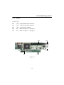
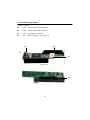
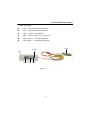
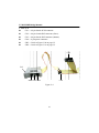
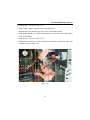
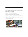
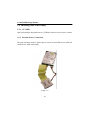
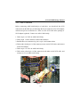
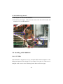
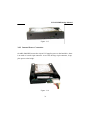
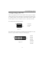
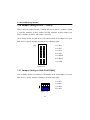
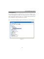
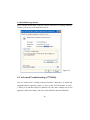
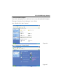
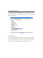
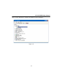
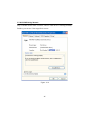
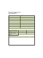
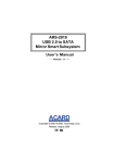
AEC-7722/AEC-7726H/Q
ARS-2100/2100Q/ARS-2120
ARS-2000LFS/ARS-2000LHS
LVD SCSI-to-IDE Bridges
User’s Manual
Version: 1.2
Copyright © 2006 ACARD Technology Corp.
Release: October 2006
Copyright and Trademarks
The information of the products in this manual is subject to change without prior
notice and does not represent a commitment on the part of the vendor, who assumes
no liability or responsibility for any errors that may appear in this manual.
ACARD and SCSIDE are the trademarks of ACARD Technology Corp. IBM is the
trademark of International Business Machine Corporation. Microsoft and the Windows Logo are the registered trademarks, and Windows is the trademark of Microsoft
Corporation. All brands and trademarks are the properties of their respective owners.
This manual contains materials protected under International Copyright Conventions. All rights reserved. No part of this manual may be reproduced in any form or
by any means, electronic or mechanical, including photocopying, without the written permission of the manufacturer and the author. All inquiries should be addressed
to ACARD Technology Corp.
WEEE Statement
English
In order to cope with the increasing waste electrical and electronic equipment, reduce the use of landfill and
incinerator, and prevent the harmful matter of waste equipment from entering the environment, the European
Union (EU) has set the Directive on Waste Electrical and Electronic Equipment (WEEE) asking manufacturers
to collect, recycle and treat waste electrical and electronic equipment properly. Member nations already
established their free of charge recycle systems of WEEE before August 13, 2005. Accordingly, ACARD has
to be responsible for recycling all products exported to Germany. You can return your ACARD product that
needs recycling to a local collector.
WEEE Erklärung
German
Mit dem Ziel die steigende Menge elektrischer und elektronischer Altgeräte zu bewältigen ohne hierzu
unnötig Mülldeponien und Verbrennungsanlagen zu belasten und um die Verschmutzung der Umwelt durch
freiwerdende Stoffe aus den Altgeräten zu vermeiden, hat die Europäische Union (EU) die Richtlinie über
Elektro- und Elektronik-Altgeräte erlassen. Die Richtlinie verpflichtet Hersteller, elektrische und elektronische
Altgeräte umweltgerecht einzusammeln, zu recyceln und zu entsorgen. Die Mitgliedsstaaten der EU haben
bereits ihre kostenfreien Recyclesysteme konform der WEEE vor dem 13. August 2005 eingerichtet.
Entsprechend der Richtlinie ist ACARD verantwortlich für die umweltgerechte Entsorgung aller nach
Deutschland exportierten ACARD Produkte. Sie können Ihr zu entsorgendes ACARD Produkt zu Ihrer
örtlichen Sammelstelle bringen.
AEEA verklaring
Dutch
Met het doel de stijgende hoeveelheid afgedankte elektrische en elektronische apparatuur te beheersen
zonder hiervoor onnodig stortplaatsen en verbrandingsovens te belasten en om de vervuiling van het milieu
door vrijkomende stoffen uit de afgedankte apparatuur te voorkomen, heeft de Europese Unie (EU) de richtlijn
betreffende afgedankte elektrische en elektronische apparatuur besloten. Deze richtlijn verplicht fabrikanten
afgedankte elektrische en elektronische apparatuur in te zamelen, te recyclen en te verwijderen. De lidstaten
van de EU hebben reeds de kosteloze recyclesystemen volgens de AEEA vóór de 13 augustus 2005
ingericht. Conform de richtlijn is ACARD verantwoordelijk voor de verwijdering van alle naar Nederland
geëxporteerde ACARD producten. U kunt uw afgedankt ACARD product naar uw locale inzamelplaats
brengen.
Turkish
(OHNWULNYH(OHNWURQLN0DGGH$WÕNODUÕ'HPHFL
(OHNWULN YH HOHFWURQLN PDGGH DWÕNODUÕQÕQ \XNVHOPHVL\OH EDVHGHELOPHN DUD]L GROGXUPD YH FRS \DNPD IÕUÕQÕ
NXOODQÕPÕQÕ
D]DOWPDNDWÕN
PDGGH
]DUDUODUÕQÕQ
FHYUH\H
\D\ÕOPDVÕQÕ
RQOHPHN
LFLQ
$YUXSD
%LUOLJL
$%XUHWLFLOHUGHQ HOHNWULN YH HOHNWURQLN PDGGH DWÕNODUÕQÕ JHUHNWLJL JLEL WRSODPDODUÕQÕJHUL GRQXVWXUPHOHULQL YH
kimyasal isleme WDEL WXWPDODUÕQÕ talep etmek icin (OHNWULN YH (OHNWURQLN 0DGGH $WÕNODUÕ X]HULQH ELU GLUHNWLI
KD]ÕUODGÕ7RSOXOXN X\HOHUL $JXVWRV WHQ RQFH HOHNWULN YH HOHNWURQLN PDGGH DWÕNODUÕQÕQ XFUHWVL] JHUL
GRQXVXPVLVWHPOHULQLFRNWDQROXVWXUPXVODUGÕ%XQGDQGROD\Õ$&$5'$OPDQ\D
\DLKUDFHWWLJLEXWXQXUXQOHULQ
geri donusumunden sorumludur.
verebilirsiniz.
$&$5' XUXQOHUL JHUL GRQXVXP JHUHNWLULUVH \HUHO WRSOD\ÕFÕODUD JHUL
WEEE [xe_l_gv
Russian
WEEE Statement
French
Qlh[u kijZ\blvky k m\_ebqb\Zxsbfky g_gm`guf we_dljbq_kdbf b we_dljhgguf
h[hjm^h\Zgb_f, mf_gvrbl_ bkihevah\Zgb_ aZdZiu\Zgby fmkhjZ b bkihevah\Zgby mklZgh\db
^ey k`b]Zgby hloh^h\, ij_iylkl\mcl_ \j_^ghfm \u[jhkZf aZ]jyagylv hdjm`Zxsmx kj_^m,
?\jhi_ckdbc khxa (?K)mklZgh\be >bj_dlb\m ih G_gm`ghfm We_dljbq_kdhfm b
We_dljhgghfm H[hjm^h\Zgbx (WEEE) ^ey lh]h, qlh[u ba]hlh\bl_e_c kh[jZeb,
i_j_jZ[Zlu\Zeb b \hh[s_ ijhy\beb \gbfZgb_ d g_gm`ghfm we_dljbq_kdhfm b we_dljhgghfm
h[hjm^h\Zgbx ^he`guf h[jZahf. Qe_gu gZpbb mklZgh\beb [_kieZlgmx kbkl_fm i_j_jZ[hldb
WEEE ^h 13 Z\]mklZ 2005. Khhl\_lkl\_ggh, ACARD h[yaZg [ulv hl\_lkl\_gguf aZ lh, qlh
i_j_jZ[hlZe \k_ ijh^mdlu, wdkihjlbjm_fu_ \ =_jfZgbx. <u fh`_l_ \ha\jZlblv \Zr ijh^mdl
ACARD, dhlhjuc gm`^Z_lky \ j_pbjdmeypbb f_klghfm k[hjsbdm.
Afin de gérer la quantité croissante de déchets électriques et électroniques, de réduire l’utilisation des
décharges et des incinérateurs et d’éviter que des déchets nocifs ne polluent l’environnement, l’Union
Européenne a publié la directive WEEE sur les déchets électriques et électroniques. Celle-ci spécifie que les
fabricants doivent collecter, recycler et traiter l’équipement électronique et électrique usagé. Depuis le 13 août
2005, les pays membres ont mis en place un système de recyclage gratuit selon le WEEE.
De ce fait, Acard est responsable du recyclage de tous les produits exportés vers l’Allemagne. Vous pouvez
mettre au rebut votre équipement ACARD usagé dans votre centre local de recyclage.
Pour plus d’informations sur les lieux de mise au rebut des équipements usagés destinés au recyclage,
veuillez contacter votre mairie, votre service de traitement des déchets ménagers ou le magasin où vous avez
acheté le produit.
RAEE
Spanish
Con la finalidad de reducir el incremento de residuos eléctricos y de material electrónico, reduciendo el uso
de los vertederos e incineradoras y prevenir el preocupante aumento del contacto de estos residuos con el
medio ambiente. Por este motivo la Unión Europea ha fijado la Directiva de Residuos de Aparatos Eléctricos
y Electrónicos (RAEE) solicitando a los fabricantes la recolección, reciclaje y tratamiento de ests residuos
correctamente. Los paises miembros ya han establecido su sistema de reciclaje gratuito de RAEE antes del
13 de Agosto del 2005. Por este motivo ACARD es el responsable del reciclaje de todos los productos
exportados a Alemania. Usted puede devolver su producto ACARD a un punto de recogida local cuando
desee reciclarlo.
Dichiarazione WEEE
Italian
Per far fronte all’aumento dei residui delle apparecchiature elettriche ed elettroniche, ridurre l'uso di materiale
di riporto e degli inceneritori, ed impedire che il materiale nocivo delle apparecchiature residue entri a contatto
con l'ambiente, l’ Unione Europea (UE) ha stabilito le Direttive sui Residui delle apparecchiature Elettriche ed
Elettroniche (WEEE) chiedendo ai fornitori di raccogliere correttamente, riciclare e trattare le apparecchiature
elettriche ed elettroniche residue. Le nazioni facenti parte dell’ Unione Europea hanno già stabilito il loro
sistema gratuito di riciclaggio di questo materiale (WEEE) prima del 13 agosto 2005. Di conseguenza,
ACARD è responsabile del riciclaggio di tutti i prodotti esportati in Germania. Potete restituire il vostro
prodotto acquistato da ACARD che deve essere riciclato da un’ azienda specifica locale.
Table of Contents
Chapter 1 About SCSIDE® ........................................................................ 5
1.1 Revolutionary Technology .......................................... 5
1.2 SCSIDE® Design ......................................................... 6
Chapter 2 Introduction ................................................. 7
2.1 Overview ...................................................................... 7
2.2 Features ....................................................................... 7
2.3 Details .......................................................................... 8
2.3.1 Package ......................................................................................... 8
2.3.2 Specifications ................................................................................ 9
2.3.3 Outlines ....................................................................................... 11
Chapter 3 Hardware Installation..............................17
3.1 Installing AEC-67160 ................................................. 17
3.2 Compatibility ............................................................. 18
3.2.1
3.2.2
3.2.3
3.2.4
Supported DVD-ROMs ............................................................. 18
Supported SCSI Adapters ......................................................... 18
Supported Recording Software ................................................ 18
Supported HDDs ........................................................................ 19
3.3 Installing AEC-7722. .................................................. 19
3.3.1 5.25” DVD-ROM ........................................................................ 19
3.3.2 Internal Power Connection ....................................................... 20
3.3.3 Cable Connection ....................................................................... 20
3.4 Installing AEC-7726H/Q ............................................ 22
3.4.1 3.5” HDD..................................................................................... 22
3.4.2 Internal Power Connection ....................................................... 22
3.4.3 Cable Connection ....................................................................... 23
3.5 Installing ARS-2100/2100Q ....................................... 24
3.5.1 3.5” HDD..................................................................................... 24
3.5.2 Internal Power Connection ....................................................... 24
3.5.3 Cable Connection ....................................................................... 25
3.6 Installing ARS-2120 ................................................... 26
3.6.1 3.5” HDD..................................................................................... 26
3.6.2 Internal Power Connection....................................................... 26
3.6.3 Cable Connection....................................................................... 27
3.7 Installing ARS-2000LFS .............................................28
3.7.1 3.5” HDD .................................................................................... 28
3.7.2 Internal Power Connection....................................................... 28
3.7.3 Cable Connection....................................................................... 29
3.8 Installing ARS-2000LHS ............................................30
3.8.1 2.5” HDD .................................................................................... 30
3.8.2 Internal Power Connection....................................................... 31
3.8.3 Cable Connection....................................................................... 32
3.9 Jumper Setting on AEC-7722 .....................................33
3.10 Jumper Setting on AEC-7726H/Q ............................34
3.11 Jumper Setting on ARS-2100/2100Q ........................34
3.12 Jumper Setting on ARS-2120 ....................................35
3.13 Jumper Setting on AEC-2000LFS ............................36
3.14 Jumper Setting on ARS-2000LHS ............................37
Chapter 4 Troubleshooting ......................................... 38
4.1 Basic Troubleshooting .................................................38
4.2 Advanced Troubleshooting of 7722 .............................39
4.3 Advanced Troubleshooting of 7726H/Q ......................42
LVD SCSIDE Bridge Manual
Chapter 1 About SCSIDE®
1.1 Revolutionary Technology
SCSIDE® is a revolutionary new technology developed by ACARD Technology
Corp. It can not only transform IDE data into SCSI type, but also save the
expenditures. Through this technology any cheap IDE device can have highperformance SCSI applications. The following examples are merely a little portion
of SCSIDE® applications.
1. To transform an IDE hard disk into an external SCSI one for notebook and desktop
PC users to back up data.
2. To transform an IDE CD-ROM or CD-R/RW into a SCSI one. It is an unprecedented
technology.
3. To transform your favorite IDE DVD-ROM, DVD-RAM/R, DVD−R/RW or
DVD+R/RW into an LVD SCSI one.
4. To daisy chain multiple SCSIDE® DVD-ROMs to create a DVD-ROM server.
5. To transform a DMA 66/100/133 hard disk of 5400rpm or 7200rpm into a SCSI
one for PC workstations, servers and even Unix workstations and servers.
The basic structure of SCSIDE® is a “System On Chip” which highly integrates
multiple CPUs. This SOC design is resulting from ACARD’s years of experiences
in the design of IDE, SCSI and RISC CPU chips. The block diagram on the next
page shows that SOC has multiple CPUs. Its ROM, RAM, DMA controllers and
external ROM interface can be used as the firmware upgrade of flash ROM. In
ACARD’s technologies there is a perfect firmware design as well. It makes the
transformation of IDE to SCSI really “plug and play”. The firmware has been tested
on many kinds of IDE DMA66 /100/133 HDDs, CD-ROMs and DVD-ROMs. No
matter your IDE device is an ATA hard disk or DVD-ROM, you all can plug it and
5
LVD SCSIDE Bridge Manual
enjoy the advantages of SCSI. With the intelligent firmware design, you don’t need
to install a driver into the operating system so as to use SCSIDE® products. In the
operating system it is just a SCSI device.
Figure 1-1
1.2 SCSIDE® Design
The objectives of SCSIDE® design are given as follows:
1. Reduce the expenses of SCSI by using a cheap IDE device.
2. Create applications like SCSI CD-ROM, high SCSI DVD-ROM, etc.
3. Apply ”plug and play” to the transformation of IDE device to SCSI one. It is not
necessary to install a driver.
Welcome to be a new member of SCSIDE® and have a good time.
6
LVD SCSIDE Bridge Manual
Chapter 2 Introduction
2.1 Overview
Thank you for purchasing AEC-7722, AEC-7726H/Q, ARS-2100/2100Q, ARS-2120,
ARS-2000LFS or ARS-2000LHS SCSI-IDE Bridge. You must feel the bridge’s
attraction in the high-tech industries worldwide after using it. Through the SCSIIDE Bridge, you can turn a cheap IDE interface into a SCSI one. The on-board core
microcontroller developed by ACARD makes the bridge more flexible, more stable
in high level applications. AEC-7722 supports DVD drives. AEC-7726H/Q, ARS2100/2100Q, ARS-2120 and ARS-2000LFS support 3.5” IDE hard drives. ARS2000LHS supports 2.5” IDE notebook hard drives. All the devices are easily
connected to SCSI bus.
2.2 Features
1. AEC-7722 and AEC-7726H/Q have the following features:
l
l
The built-in RISC CPU, SCSI, IDE controllers and interfaces on the chip.
The synchronous transfer rate of SCSI host interface is 80MB/sec in AEC7722 and 160MB/sec in AEC-7726H/Q.
l
l
The full support of SCSI target features.
The programmable IDE access modes, including
PIO mode 0, 1, 2, 3, 4
Multiword DMA mode 0, 1, 2
Ultra DMA mode 0~5 (transfer rate is 66MB/sec in AEC-7722 and 133MB/
sec in AEC-7726H/Q).
l
The on-board flash ROM is easy to update firmware.
7
LVD SCSIDE Bridge Manual
2. ARS-2100/2100Q, ARS-2120, ARS-2000LFS and ARS-2000LHS have the
following features:
l Easy to install.
l
l
l
l
l
On-chip high speed ACARD RISC microcontroller.
The transfer rate of LVD SCSI interface up to 160MB/sec.
Supports ATA 66/100/133 HDD.
The on-board flash ROM is easy to update firmware.
Supprts cross-platform operating systems like Windows 98/ME/NT/2000/XP,
Linux, Mac and Sun.
l
l
Selectable SCSI ID from 0 to 15.
Supports two IDE hard drives in JBOD or Normal mode (ARS-2120 only).
In addition, ARS-2000LFS and ARS-2000LHS are highly efficient in system’s I/O
performance.
2.3 Details
2.3.1 Package
Check the following items after opening the package:
l
AEC-7722, AEC-7726H/Q, ARS-2100/2100Q, ARS-2120,
ARS-2000LFS or ARS-2000LHS.
l
l
l
l
Y-splitter power cord (except ARS-2000LHS).
AEC-67160 SCSI adapter (optional).
4 screws for ARS-2000LFS or ARS-2000LHS.
User’s manual.
8
LVD SCSIDE Bridge Manual
2.3.2 Specifications
t
AEC-7722
Environment:
Temperature
0°C to 50°C for operation
−20°C to 85°C for storage
Humidity
Dimension:
15% to 90%
L 12 cm
W 3.5 cm
H
t
2.5 cmm
AEC-7726H/Q
Environment:
Temperature
0°C to 50°C for operation
−20°C to 85°C for storage
Humidity
Dimension:
15% to 90%
L 9.8 cm
W 4 cm
H
t
2.3 cm
ARS-2100/2100Q/ARS-2120
Environment:
Temperature
0°C to 50°C for operation
−20°C to 85°C for storage
Humidity
15% to 90%
9
LVD SCSIDE Bridge Manual
Dimension
L 11.5 cm
W 7.1 cm
H
2
cm
t
ARS-2000LFS
Environment:
Temperature
0°C to 50°C for operation
−20°C to 85°C for storage
Humidity
Dimension:
15% to 90%
L 13.8 cm
W 10.2 cm
H 1.3 cm
t
ARS-2000LHS
Environment:
Temperature
0°C to 50°C for operation
−20°C to 85°C for storage
Humidity
Dimension:
15% to 90%
L 13.8 cm
W 10.2 cm
H 2.4 cm
10
LVD SCSIDE Bridge Manual
2.3.3 Outlines
1. AEC-7722
l
l
l
l
l
CN1--- 68-pin female SCSI connector.
CN2 --- 40-pin female IDE connector.
CN3 --- 4-pin power connector.
JP1 --- Refer to Figure 3-16 on page 33.
JP2 --- Refer to Figure 3-17 on page 33.
CN1
left
JP1
CN3
JP2
CN2
Figure 2-1
11
LVD SCSIDE Bridge Manual
2. AEC-7726H/Q
l
l
l
l
CN1 --- 68-pin female SCSI connector.
CN2 --- 40-pin female IDE connector.
CN3 --- 4-pin power connector.
JP1 --- Refer to Figure 3-18 on page 34.
JP1
CN1
Top
CN3
Figure 2-2a
CN2
Figure 2-2b
12
LVD SCSIDE Bridge Manual
3. ARS-2100/2100Q
l
l
l
l
l
l
CN1 --- 68-pin female SCSI connector.
CN2 --- 40-pin female IDE connector.
CN3 --- 4-pin power connector.
SW1 --- Refer to Figure 3-19 on page 34.
LED1 (Green) --- for indicating power.
LED2 (Red) --- for indicating operation.
CN2
CN1
LED2
SW1 CN3 LED1
Figure 2-3
13
LVD SCSIDE Bridge Manual
4. ARS-2120
l
l
l
l
l
l
CN1 --- 68-pin female SCSI connector.
CN2 --- 40-pin female IDE connector (Slave).
CN3 --- 40-pin female IDE connector (Master).
CN4 --- 4-pin power connector.
SW1 --- Refer to Figure 3-20 on page 35.
SW2 --- Refer to Figure 3-21 on page 35.
CN3
CN1
SW1 CN4 SW2
CN2
Figure 2-4
14
LVD SCSIDE Bridge Manual
5. ARS-2000LFS
l
l
l
l
l
l
CN1 --- 68-pin female SCSI connector.
CN2 --- 40-pin female IDE connector.
CN3 --- 4-pin power connector, for supplying power to HDD.
CN4 --- 4-pin power connector, for supplying power to the bridge.
JP1 --- Refer to Figure 3-22 on page 36.
SW1 --- Refer to Figure 3-23 on page 36
CN3 SW1
CN4
JP1
CN2
CN1
Figure 2-5
15
LVD SCSIDE Bridge Manual
6. ARS-2000LHS
l
l
l
l
l
CN1 --- 68-pin female SCSI connector.
CN5 --- 44-pin female IDE connector.
CN4 --- 4-pin power connector, for supplying power to the bridge.
JP1 --- Refer to Figure 3-24 on page 37.
SW1 --- Refer to Figure 3-25 on page 37.
SW1
CN4
JP1
CN5
CN1
Figure 2-6
16
LVD SCSIDE Bridge Manual
Chapter 3 Hardware Installation
Hardware installation includes two parts. The first part is the installation of SCSI
adapter like AEC-67160. The second part is the installation of AEC-7722 or AEC7726H/Q, etc. Yet, you have to set jumpers at first (see page 33-37).
If your old hard drive contains an OS, you had better partition and install the OS
again. In DOS and Windows it is all right without installing anew, but the different
commands on the SCSI adapter and IDE controller will result in read/write errors.
Therefore, after installation regard the IDE hard drive as a brand-new one.
3.1 Installing AEC-67160
Refer to the manual of AEC-67160 to install the driver before installing the SCSI
adapter. If the driver on the CD is not the newest version, you need to download it
from Internet onto a floppy, and then install it into your computer. The Web site of
ACARD is http://www.acard.com.
Insert the PCI edge connector of SCSI adapter firmly into PCI slot so as to connect
other devices internally or externally.
Figure 3-1
17
LVD SCSIDE Bridge Manual
3.2 Compatibility
3.2.1 Supported DVD-ROMs
AEC-7722 is particularly designed for DVD drive. It has been tested, and perfectly
supports every major kind of DVD-ROM/DVD writer with different generation and
speed. It supports the following brands.
l
l
l
l
l
l
l
AOPEN
ASUS
Liteon
Panasonic
Pioneer
RICOH
Sony
l
l
l
l
l
l
l
TEAC
LG
HP
NEC
Plextor
SANYO
MATSUSHITA
3.2.2 Supported SCSI Adapters
Through AEC-7722 an IDE DVD drive can be transformed into a SCSI one, but
most CD recording software still regards it as an IDE one . Thus the recording software will send 12-byte IDE commands. Only a special SCSI adapter such as AEC67160 can solve the problem.
3.2.3 Supported Recording Software
In order to make an IDE DVD writer work stably and normally after being transformed into a SCSI one, it needs not only a SCSI adapter, but also fine recording
software like the following ones.
l
l
ACARD Ha! CD Burner (+DVD)
Nero Burning Rom
18
LVD SCSIDE Bridge Manual
3.2.4 Supported HDDs
AEC-7726H/Q, ARS-2100/ARS-2100Q, ARS-2120 and ARS-2000LFS are designed
for 3.5” HDD. ARS-2000LHS is for 2.5” DMA HDD. They have been tested, and
support the following brands.
3.5” HDD
l
l
l
l
IBM HDD
MAXTOR HDD
SEAGATE HDD
WESTERN DIGITAL HDD
2.5” HDD
l
l
IBM HDD
Fujitsu HDD
3.3 Installing AEC-7722
3.3.1 5.25” DVD-ROM
AEC-7722 is designed to meet 5.25” DVD-ROMs or DVD writers. Extra accessories are not needed in installaiton.
19
LVD SCSIDE Bridge Manual
3.3.2 Internal Power Connection
The large connector of the Y-splitter power cord is for most IDE devices while the
small one for AEC-7722.
Figure 3-2
3.3.3 Cable Connection
Before connecting AEC-7722 to a DVD drive, you should tell the SCSI connector
from the IDE one. On the bridge the 68-pin connector is for SCSI adapter while the
40-pin one for IDE device. There is a new SCSI cable in the package of SCSI adapter
(optional). Connect it to AEC-7722.
20
LVD SCSIDE Bridge Manual
1. Find out pin 1 of CN2 on AEC-7722.
2. Find out pin 1 of the connector on the IDE DVD drive.
3. Parallel these two connectors by pin 1 to pin 1 and connect them.
4. Find out the colored pin 1 of the connector on one end of SCSI cable, and connect
to the SCSI adapter.
5. Find out pin 1 of CN1 on AEC-7722.
6. Find out the colored pin 1 of the connector on the other end of SCSI cable, and
connect to CN1 of AEC-7722.
Figure 3-3
21
LVD SCSIDE Bridge Manual
3.4 Installing AEC-7726H/Q
3.4.1 3.5” HDD
AEC-7726H/Q is designed for ATA hard drive. Extra accessories aren’t needed.
3.4.2 Internal Power Connection
There are two kinds of internal power connectors providing power to the IDE device
and AEC-7726H/Q circuit board separately. The large connector of the Y-splitter
power cord is for most IDE devices while the small one for AEC-7726H/Q.
Figure 3-4
22
LVD SCSIDE Bridge Manual
3.4.3 Cable Connection
Before connecting AEC-7726H/Q to a hard drive, you should tell the SCSI connector
from the IDE one. On the bridge the 68-pin connector is for SCSI adapter while the
40-pin one for IDE device. There is a new SCSI cable in the package of SCSI adapter
(optional). Connect it to AEC-7726H/Q.
1. Find out pin 1 of CN2 on AEC-7726H/Q.
2. Find out pin 1 of the connector on the IDE hard drive.
3. Parallel these two connectors by pin 1 to pin 1 and connect them.
4. Find out the colored pin 1 of the connector on one end of SCSI cable, and connect
to the SCSI adapter.
5. Find out pin 1 of CN1 on AEC-7726H/Q.
6. Find out the colored pin 1 of the connector on the other end of SCSI cable, and
connect to CN1 of AEC-7726H/Q.
Figure 3-5
23
LVD SCSIDE Bridge Manual
3.5 Installing ARS-2100/2100Q
3.5.1 3.5” HDD
ARS-2100/2100Q is designed to meet 3.5”HDDs. Extra accessories aren’t needed.
3.5.2 Internal Power Connection
The large connector of the Y-splitter power cord is for most IDE devices while the
small one for ARS-2100/2100Q.
Figure 3-6
24
LVD SCSIDE Bridge Manual
3.5.3 Cable Connection
Before connecting ARS-2100/2100Q to a hard drive, you should tell the SCSI
connector from the IDE one. On the bridge the 68-pin connector is for SCSI adapter
while the 40-pin one for IDE device. There is a new SCSI cable in the package of
SCSI adapter (optional). Connect it to ARS-2100/2100Q.
1. Find out pin 1 of CN2 on ARS-2100/2100Q.
2. Find out pin 1 of the connector on the IDE hard drive.
3. Parallel these two connectors by pin 1 to pin 1 and connect them.
4. Find out the colored pin 1 of the connector on one end of SCSI cable, and connect
to the SCSI adapter.
5. Find out pin 1 of CN1 on ARS-2100/2100Q.
6. Find out the colored pin 1 of the connector on the other end of SCSI cable, and
connect to CN1 of ARS-2100/2100Q.
Figure 3-7
25
LVD SCSIDE Bridge Manual
3.6 Installing ARS-2120
3.6.1 3.5” HDD
ARS-2120 is designed to connect two 3.5”HDDs. Extra accessories aren’t needed.
3.6.2 Internal Power Connection
The large connector of the Y-splitter power cord is for most IDE devices while the
small one for ARS-2120. Note that the first hard drive should be set as Master while
the second one as Slave.
Slave (the 2nd HDD)
Figure 3-8
26
Master (the 1st HDD)
LVD SCSIDE Bridge Manual
3.6.3 Cable Connection
Before connecting ARS-2120 to 2 hard drives, you should tell the SCSI connector
from the IDE one. On the bridge the 68-pin connector is for SCSI adapter while the
40-pin one for IDE device. There is a new SCSI cable in the package of SCSI adapter
(optional). Connect it to ARS-2120.
1. Find out pin 1 of CN2 (CN3)on ARS-2120.
2. Find out pin 1 of the connector on the 1st (2nd) hard drive.
3. Parallel these two connectors by pin 1 to pin 1 and connect them.
4. Set the 1st (2nd) hard drive as Master (Slave).
5. Connect one end of SCSI cable to the SCSI adapter by finding out pin1.
6. Find out pin 1 of CN1 on ARS-2120.
7. Find out the colored pin 1 of the connector on the other end of SCSI cable, and
connect to CN1 of ARS-2120.
Figure 3-9
27
LVD SCSIDE Bridge Manual
3.7 Installing ARS-2000LFS
3.7.1 3.5” HDD
ARS-2000LFS is designed to meet 3.5”HDDs. Put the hard drive on the bridge and
connect it to the 40-pin CN2 (see Figure 2-5 on page 15). Then screw it from the
bottom with 4 golden screws as the following picture shows.
Figure 3-10
3.7.2 Internal Power Connection
There are two kinds of power connectors supplying power to the IDE device and
ARS-2000LFS separately. CN4 is the large connector for ARS-2000LFS while CN3
the small one for hard drive. After connection, CN3 will be invisible when viewing
from the outside. See the picture on the next page.
28
LVD SCSIDE Bridge Manual
Figure 3-11
3.7.3 Cable Connection
Before connecting ARS-2000LFS to a hard drive, you should tell the SCSI connector
from the IDE one. On the bridge the 68-pin connector is for SCSI adapter while the
40-pin one for IDE device. There is a new SCSI cable in the package of SCSI adapter
(optional). Connect it to ARS-2000LFS.
1. Find out pin 1 of CN2 on ARS-2000LFS.
2. Find out pin 1 of the connector on the IDE hard drive.
3. Parallel these two connectors by pin 1 to pin 1 and connect them.
4. Find out the colored pin 1 of the connector on one end of SCSI cable, and connect
to the SCSI adapter.
29
LVD SCSIDE Bridge Manual
5. Find out pin 1 of CN1 on ARS-2000LFS.
6. Find out the colored pin 1 of the connector on the other end of SCSI cable, and
connect to CN1 of ARS-2000LFS.
Figure 3-12
3.8 Installing ARS-2000LHS
3.8.1 2.5” HDD
ARS-2000LHS is designed to meet 2.5” notebook HDDs. Put the hard drive on the
bridge and connect it to the 44-pin CN5 (see Figure 2-6 on page 16). Then screw it
alongside with 4 screws as the following picture shows on the next page.
30
LVD SCSIDE Bridge Manual
Figure 3-13
3.8.2 Internal Power Connection
On ARS-2000LHS because the 44-pin CN5 supplies power to the hard drive, there
is no need of a small 4-pin connector. As to CN4, the large 4-pin connector, it supplies power to the bridge.
Figure 3-14
31
LVD SCSIDE Bridge Manual
3.8.3 Cable Connection
Before connecting ARS-2000LHS to a hard drive, you should tell the SCSI connector
from the IDE one. On the bridge the 68-pin connector is for SCSI adapter while the
44-pin one for IDE device. There is a new SCSI cable in the package of SCSI adapter
(optional). Connect it to ARS-2000LHS.
1. Find out pin 1 of CN2 on ARS-2000LHS.
2. Find out pin 1 of the connector on the IDE hard drive.
3. Parallel these two connectors by pin 1 to pin 1 and connect them.
4. Find out the colored pin 1 of the connector on one end of SCSI cable, and connect
to the SCSI adapter.
5. Find out pin 1 of CN1 on ARS-2000LHS.
6. Find out the colored pin 1 of the connector on the other end of SCSI cable, and
connect to CN1 of ARS-2000LHS.
Figure 3-15
32
LVD SCSIDE Bridge Manual
3.9 Jumper Setting on AEC-7722
There are two jumpers on AEC-7722: JP1 and JP2. JP1 has 6 pins in 3 columns.
Column 1 and 2 are for reserve, and column 3 is for single end (SE). JP2 has 14 pins
in 7 columns. Column 1 is for ID1, column 2 for ID2, column 3 for ID4, column 4
for ID8, column 5 for reserve 0, column 6 for reserve 1, and column 7 for LED.
JP1 is mainly used to set for single end (SE).
left
1 for reserve
2 for reserve
right
1
2
3 for SE
3
Figure 3-16
JP2 is mainly used to set each device’s ID number on the SCSI adapter. Give your
IDE device a specific number according to the following figure.
1 for ID1
left
2 for ID2
right
3 for ID4
4 for ID8
1
2
3
4
5
6
7
5 for RSV0
Figure 3-17
6 for RSV1
7 for LED
33
LVD SCSIDE Bridge Manual
3.10 Jumper Setting on AEC-7726H/Q
There is only one jumper on AEC-7726H/Q. JP1 has 14 pins in 7 columns. Column
1 is for ID1, column 2 for ID2, column 3 for ID4, column 4 for ID8, column 5 for
RSV0, column 6 for RSV1 and column 7 for LED.
JP1 is mainly used to set each device’s ID number on the SCSI adatper. Give your
IDE device a specific number according to the following figure.
top
1 for ID1
2 for ID2
3 for ID4
4 for ID8
5 for RSV0
6 for RSV1
7 for LED
Figure 3-18
3.11 Jumper Setting on ARS-2100/2100Q
SW1 is mainly used to set each device’s ID number on the SCSI adatper. Give your
IDE device a specific number according to the following figure.
1 for ID1
2 for ID2
3 for ID4
ON
1
2
3
4
Figure 3-19
34
4 for ID8
LVD SCSIDE Bridge Manual
3.12 Jumper Setting on ARS-2120
SW1 is mainly used to set each device’s ID number on the SCSI adatper. Give your
IDE device a specific number according to the following figure.
1 for ID1
2 for ID2
3 for ID4
ON
1
2
3
4
4 for ID8
Figure 3-20
SW2 is used to set the function of SCSI adapter. Give your IDE device a specific
function according to the following figure.
1 OFF for JBOD
1 ON for Normal
ON
1
2
2 for reserve
Figure 3-21
NOTICE: In Normal mode there is no RAID functions.
Please set LUN as enable. (refer to user’s manual of SCSI)
35
LVD SCSIDE Bridge Manual
3.13 Jumper Setting on ARS-2000LFS
There is one jumper on ARS-2000LFS. JP1 has 10 pins in 5 columns. Column 1 is
for ID1, column 2 for ID2, column 3 for ID4, column 4 for ID8, and column 5 for
delay start (to control the drive’s spin-up).
JP1 is mainly used to set each device’s ID number on the SCSI adatper. Give your
IDE device a specific number according to the following figure.
left
1 for ID1
2 for ID2
right
1
2
3
4
5
3 for ID4
4 for ID8
Figure 3-22
5 for delay start
(control the drive’s spin-up)
Besides, there is a SW1 on ARS-2000LFS. Its definition is as the following figure
shows.
1 for Force Single End
2 for RSV0
3 for RSV1
1
2
3
Figure 3-23
36
4
4 for RSV2
LVD SCSIDE Bridge Manual
3.14 Jumper Setting on ARS-2000LHS
There is one jumper on ARS-2000LHS. JP1 has 10 pins in 5 columns. Column 1 is
for ID1, column 2 for ID2, column 3 for ID4, column 4 for ID8, and column 5 for
reserve.
JP1 is mainly used to set each device’s ID number on the SCSI adatper. Give your
IDE device a specific number according to the following figure.
1 for ID1
2 for ID2
left
3 for ID4
right
4 for ID8
5 for reserve
1
2
3
4
5
Figure 3-24
Besides, there is a SW1 on ARS-2000LHS. Its definition is as the following figure
shows.
1 for Force Single End
2 for RSV0
3 for RSV1
1
2
3
4
Figure 3-25
37
4 for RSV2
LVD SCSIDE Bridge Manual
Chapter 4 Troubleshooting
4.1 Basic Troubleshooting
After installing AEC-7722, AEC-7726H/Q, ARS-2100/ARS-2100Q, ARS-2120,
ARS-2000LFS or ARS-2000LHS, if it cannot work, check the following things.
1. Check SCSI host adapter
Check if the adapter is firmly inserted into PCI slot on the motherboard.
2. Check all connectors and SCSI cable
Check if the power connector, SCSI connector, IDE connector on the bridge, the
power connector on the IDE device, and the cable are all properly connected. The
cable is easily damaged due to folds. You can use a new cable. Be sure that the pins
inside the connectors are not bent, and the two colored pin 1s on both ends of the
cable are corresponding to the pin 1 on CN1 of the bridge and the pin 1 on SCSI
adapter respectively.
3. Check jumper setting
Configure the bridge to check if the jumper setting is right.
4. SCSI ID Number
If there are many SCSI devices, be sure that ID numbers are not conflicted with one
another. Test every SCSI device so as to reduce the failure of ID switch.
5. External Cable
In daisy chain if the external cable is not a highly dense 68-pin one, the emitted
signal will be weak. Under such circumstances use a better cable.
38
LVD SCSIDE Bridge Manual
4.2 Advanced Troubleshooting of 7722
Here we connect AEC-7722 to RICOH MP5120A, a DVD drive, to explain the
troubleshooting in operating system. At first, set the SCSI ID number on AEC-7722
as 0, and then inspect in Windows XP.
1. Check SCSI host adapter
Check if the displayed device on the list of devices is just the installed SCSI adapter.
The steps of entering “Device Manager” are as follows.
Step1. Double click “My Computer”.
Figure 4-1
39
LVD SCSIDE Bridge Manual
Step 2. Double click “Control Panel”.
Figure 4-2
Step 3. Double click “Printers and Other Hardware”. Then, double click “System”
on the left. After entering “System Properties”, click “Hardware”, “Device Manager”. Then, double click “SCSI and RAID controllers” to check if AEC-67160
adapter is installed well.
Figure 4-3
40
LVD SCSIDE Bridge Manual
2. Check IDE device
If you can find the IDE device connected to AEC-7722 in “Device Manager”, AEC7722 has been installed successfully. If you cannot find, but see a yellow question
mark, check the IDE connector on AEC-7722. It could be a bad connection or the
device’s malfunction. Check your IDE device as follows.
Step 1. Click “DVD/CD-ROM” to show your DVD device in “Device Manager”.
Figure 4-4
41
LVD SCSIDE Bridge Manual
Step 2. Double click to enter “General”, and see if the device is working normally.
Besides, you can see if the target ID is correct.
Figure 4-5
4.3 Advanced Troubleshooting of 7726H/Q
Here we connect AEC-7726H/Q to Maxtor 6L040J2, a hard drive, to explain the
troubleshooting in operating system. At first, set the SCSI ID number on AEC7726H/Q as 0, and then inspect in Windows XP. The same example can be also
applied to ARS-2100/2100Q, ARS-2120, ARS-2000LFS and ARS-2000LHS.
42
LVD SCSIDE Bridge Manual
1. Check SCSI host adapter
Check if the displayed device on the list of devices is just the installed SCSI adapter.
The steps of entering “Device Manager” are as follows.
Step1. Double click “My Computer”.
Figure 4-6
Step 2. Double click “Control Panel”.
Figure 4-7
43
LVD SCSIDE Bridge Manual
Step 3. Double click “Printers and Other Hardware”. Then, double click “System”
on the left. After entering “System Properties”, click “Hardware”, “Device Manager”. Then, double click “SCSI and RAID controllers” to check if AEC-67160
adapter is installed well.
Figure 4-8
2. Check IDE device
If you can find the IDE device connected to AEC-7726H/Q in “Device Manager”,
AEC-7726H/Q has been installed successfully. If you cannot find, but see a yellow
question mark, check the IDE connector on AEC-7726H/Q. It could be a bad connection or the device’s malfunction. Check your IDE device as follows.
44
LVD SCSIDE Bridge Manual
Step 1. Click “Disk drives” to show your HDD in “Device Manager”.
Figure 4-9
45
LVD SCSIDE Bridge Manual
Step 2. Double click to enter “General”, and see if the device is working normally.
Besides, you can see if the target ID is correct.
Figure 4-10
46
Technical Support Form
Email: [email protected]
http://www.acard.com
Model
Hard Disk Model/type
Capacity
Firmware version
Others
Problem Description
F/W Version