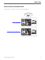
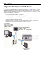
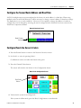
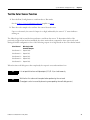
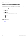
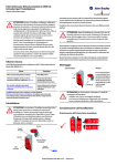
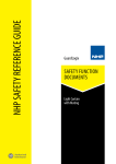
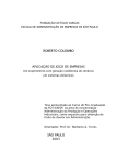
1
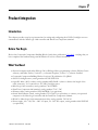
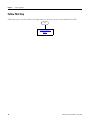
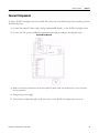
Teaching Color-Sensing Connected
Components Building Block
Quick Start
Important User Information
Solid state equipment has operational characteristics differing from those of electromechanical equipment. Safety Guidelines for the
Application, Installation and Maintenance of Solid State Controls (publication SGI-1.1 available from your local Rockwell Automation sales
office or online at http://literature.rockwellautomation.com) describes some important differences between solid state equipment and hardwired electromechanical devices. Because of this difference, and also because of the wide variety of uses for solid state equipment, all
persons responsible for applying this equipment must satisfy themselves that each intended application of this equipment is acceptable.
In no event will Rockwell Automation, Inc. be responsible or liable for indirect or consequential damages resulting from the use or
application of this equipment.
The examples and diagrams in this manual are included solely for illustrative purposes. Because of the many variables and requirements
associated with any particular installation, Rockwell Automation, Inc. cannot assume responsibility or liability for actual use based on the
examples and diagrams.
No patent liability is assumed by Rockwell Automation, Inc. with respect to use of information, circuits, equipment, or software described in
this manual.
Reproduction of the contents of this manual, in whole or in part, without written permission of Rockwell Automation, Inc., is prohibited.
Throughout this manual, when necessary, we use notes to make you aware of safety considerations.
WARNING
IMPORTANT
Identifies information about practices or circumstances that can cause an explosion in a hazardous environment, which may
lead to personal injury or death, property damage, or economic loss.
Identifies information that is critical for successful application and understanding of the product.
ATTENTION
Identifies information about practices or circumstances that can lead to personal injury or death, property damage, or economic
loss. Attentions help you identify a hazard, avoid a hazard, and recognize the consequences.
SHOCK HAZARD
Labels may be on or inside the equipment, for example, a drive or motor, to alert people that dangerous voltage may be present.
BURN HAZARD
Labels may be on or inside the equipment, for example, a drive or motor, to alert people that surfaces may reach dangerous
temperatures.
Rockwell Automation, Allen-Bradley, ColorSight, MicroLogix, PanelView, RSLinx Classic, RSLogix 500, RSLogix Micro, Stratix, and TechConnect are trademarks of Rockwell Automation, Inc.
Trademarks not belonging to Rockwell Automation are property of their respective companies.
Where to Start
Connected Components Building Block Outline
Follow the path below to complete your connected components building block.
Connected Components
Building Blocks, publication
CC-QS001
Chapter 1 Product Integration
Chapter 2 System Validation and Application Tips
3Publication CC-QS010A-EN-P - May 2009
3
Where to Start
Notes:
4
Publication CC-QS010A-EN-P - May 2009
Table of Contents
Preface
Introduction . . . . . . . . . . . . . . . . . . . . . . . . . . . . . . . . . . . . . . . . . . . . . . . 7
Conventions Used in This Manual . . . . . . . . . . . . . . . . . . . . . . . . . . . . . 8
Additional Resources . . . . . . . . . . . . . . . . . . . . . . . . . . . . . . . . . . . . . . . . 8
Chapter 1
Product Integration
Introduction . . . . . . . . . . . . . . . . . . . . . . . . . . . . . . . . . . . . . . . . . . . . . . . 9
Before You Begin. . . . . . . . . . . . . . . . . . . . . . . . . . . . . . . . . . . . . . . . . . . 9
What You Need . . . . . . . . . . . . . . . . . . . . . . . . . . . . . . . . . . . . . . . . . . . . 9
Follow This Step . . . . . . . . . . . . . . . . . . . . . . . . . . . . . . . . . . . . . . . . . . 10
Connect Components . . . . . . . . . . . . . . . . . . . . . . . . . . . . . . . . . . . . . . 11
Configuring PanelView Component Terminal IP Addresses . . . . . . . 12
Chapter 2
System Validation and Application Introduction . . . . . . . . . . . . . . . . . . . . . . . . . . . . . . . . . . . . . . . . . . . . . . 13
Before You Begin. . . . . . . . . . . . . . . . . . . . . . . . . . . . . . . . . . . . . . . . . . 13
Tips
What You Need . . . . . . . . . . . . . . . . . . . . . . . . . . . . . . . . . . . . . . . . . . . 13
Follow These Steps . . . . . . . . . . . . . . . . . . . . . . . . . . . . . . . . . . . . . . . . 14
Overview of System Operation . . . . . . . . . . . . . . . . . . . . . . . . . . . . . . . 14
Configure the Sensor Node Address and Baud Rate . . . . . . . . . . . . . . 15
Configure/Teach the Sensor’s Colors. . . . . . . . . . . . . . . . . . . . . . . . . . 15
Test the Color Sensor Function . . . . . . . . . . . . . . . . . . . . . . . . . . . . . . 17
Resetting the 45CLR ColorSight Sensor to Factory Defaults . . . . . . . 18
5Publication CC-QS010A-EN-P - May 2009
5
Table of Contents
Notes:
6
Publication CC-QS010A-EN-P - May 2009
Preface
Introduction
This Quick Start demonstrates the setup and functionality of the 45CLR
ColorSight sensor over an RS-485 network. In this application, the sensor is
taught five colors that are then stored in the sensor’s internal memory. Once
configured and in Run mode, the sensor continuously scans colors presented
in the detection area. Upon a color match, the sensor’s output is triggered.
This initiates a read request from the MicroLogix 1400 controller, and the red,
green, and intensity values retrieved are compared to those stored in the
sensor’s memory to determine which color has been matched; this, in turn,
switches on a corresponding discrete output on the MicroLogix 1400
controller.
IMPORTANT
Use this Teaching Color-Sensing Connected Components
Building Block Quick Start in conjunction with the Connected
Components Building Blocks Quick Start, publication CC-QS001.
Refer to Additional Resources on page 8 for a listing of Quick
Start documents.
To assist in the design and installation of your system, application files and
other information are provided on the Connected Component Building
Blocks Overview CD, publication CC-QR001. The CD provides bills of
materials (BOMs), CAD drawings for panel layout and wiring, control
programs, Human Machine Interface (HMI) screens, and more. With these
tools and the built-in best-practices design, the system designer is free to focus
on the design of their machine control and not on design overhead tasks.
The beginning of each chapter contains the following information. Read these
sections carefully before beginning work in each chapter:
• Before You Begin - This section lists the steps that must be completed
and decisions that must be made before starting that chapter. The
chapters in this quick start do not have to be completed in the order in
which they appear, but this section defines the minimum amount of
preparation required before completing the current chapter.
• What You Need - This section lists the tools that are required to
complete the steps in the current chapter. This includes, but is not
limited to, hardware and software.
• Follow These Steps - This illustrates the steps in the current chapter
and identifies which steps are required to complete the examples.
Publication CC-QS010A-EN-P - May 2009
7
Preface
Conventions Used in This
Manual
This manual uses the following conventions.
Convention
Meaning
Example
Enter
Select from a pull-down menu.
Enter the Catalog Number of the product.
Press
Press a specific button on the PanelView Component (PVc)
terminal.
Press the Channel Values button.
Additional Resources
Resource
Description
Connected Components Building Blocks Quick Start, Provides information on how to select products and gain access to panel and wiring
publication CC-QS001
information.
Connected Component Building Blocks Overview
CD, publication CC-QR001
Provides files for the Connected Component Building Blocks.
ColorSight True Color Sensor RS-485
Communications User Manual, publication number
45CLR-UM001
Provides information on the installation, setup, and operation of the 45CLR
ColorSight sensor.
MicroLogix 1400 User Manual, publication 1766UM001
Provides information on using the MicroLogix 1400 programmable controller.
PanelView Component HMI Terminals User Manual, Provides information on using the PanelView Component HMI Terminals.
publication 2711C-UM001
http://www.ab.com
Provides access to the Allen-Bradley website.
http://rockwellautomation.com/knowledgebase
Provides access to self-service support.
http://www.rockwellautomation.com/components/
connected
Provides access to the Connected Components website.
8
Publication CC-QS010A-EN-P - May 2009
Chapter
1
Product Integration
Introduction
This chapter provides step-by-step instructions for wiring and configuring the 45CLR ColorSight sensor to
communicate with the MicroLogix 1400 controller and PanelView Component terminal.
Before You Begin
Review the Connected Components Building Blocks Quick Start, publication CC-QS001, verifying that you
have completed the hardware design and installation as well as software installation.
What You Need
• Personal computer with either RSLogix 500 or RSLogix Micro programming software, RSLinx Classic
software, and either Firefox, Version 2.x, or Internet Explorer, Version 7.x, software installed
• Connected Component Building Blocks Overview CD, publication CC-QR001
• 45CLR ColorSight sensor, catalog number 45CLR-5LPS1-D8
• 8-pin DC Micro (M12) cordset, catalog number 889D-F8AB-x (where x denotes the length of the
cable, in meters) - for connection to 45 CLR ColorSight sensor
• MicroLogix 1400 controller, catalog number 1766-L32BXB
• PanelView Component 600 terminal, catalog number 2711C -T6C
• Ethernet cables, catalog number 1585J-M8TBJM-2 (or equivalent)
• Stratix 2000 Ethernet switch, catalog number 1783-US05T (or equivalent), to connect your personal
computer to the MicroLogix controller and the PanelView Component terminal
• RS-485 to MicroLogix 1400 communication cable, catalog number 1763-NC01
• Power supply, 100…120/220…240V AC input, 24…28V DC output, catalog number 1606-XLP30E
(or equivalent)
9Publication CC-QS010A-EN-P - May 2009
9
Chapter 1
Product Integration
Follow This Step
Follow this step to wire the 45CLR ColorSight sensor to the power source and communication cable.
Start
Connect Components,
page 11
10
Publication CC-QS010A-EN-P - May 2009
Product Integration
Chapter 1
Connect Components
To wire a 45CLR ColorSight sensor into the RS-485 connection of the MicroLogix 1400 controller, perform
the following steps.
1. Connect the 8-pin DC Micro cable, catalog number 889D-F8AB-x, to the 45CLR ColorSight sensor.
2. Connect 24V DC power and RS-485 communication wiring according to the diagram below.
System Wiring Diagram
3. Make sure that the unused wires from the 8-pin DC Micro cable are insulated to be sure of correct
system operation.
4. Energize the power supply.
5. Verify that the round white light on the sensor face of the 45CLR ColorSight sensor turns on.
Publication CC-QS010A-EN-P - May 2009
11
Chapter 1
Product Integration
Configuring PanelView Component Terminal IP Addresses
In the Connected Components Building Blocks Quick Start, publication CC-QS001, Chapter 3 - Controller
and HMI Integration details how to set the Ethernet IP addresses in the MicroLogix 1400 controller and
PanelView Component 600 terminal. If you have not done this already, follow those instructions to set the
following static IP addresses in your devices.
• Set the personal computer IP address to 192.168.1.3.
• Set the PanelView Component terminal IP address to 192.168.1.4.
• Set the MicroLogix 1400 controller IP address to 192.168.1.2.
• Follow the instructions in the Load Your HMI Screens section of Chapter 3 to transfer your HMI
screens to the PanelView Component terminal.
• Follow the instructions in the Load Your Control Program section of Chapter 3 to transfer your
control program to the MicroLogix controller for use in your application.
- Personal Computer
- Firefox, Version 2.x, or Internet
Explorer, Version 7.x, Software
- IP Address 192.168.1.3
- Either RSLogix 500 or RSLogix
Micro Software
- RSLinx Classic Software
Ethernet
- PanelView Component 600 Terminal
- IP Address 192.168.1.4
- With Teac h-in_CCBB_001.cha file loaded
Ethernet
- MicroLogix 1400 Controller
- IP Address 192.168.1.2
- With Color Sensing Teach-in_CCBB_001 file
loaded
AB Stratix
Ethernet Switch
RS-485 Cable
Ethernet
45CLR ColorSight Sensor,
Node Address 1
12
Publication CC-QS010A-EN-P - May 2009
Chapter
1
System Validation and Application Tips
Introduction
In this chapter, you will run and validate the operation of the 45CLR ColorSight sensor with the MicroLogix
1400 controller and PanelView Component 600 terminal. You will also teach the sensor five colors and test
the color-sensing function.
Before You Begin
• Verify that you have completed all of the steps in Chapter 1 of this document.
• Review the MicroLogix 1400 User Manual, publication 1766-UM001.
• Review PanelView Component HMI Terminals User Manual, publication 2711C-UM001.
• Review the ColorSight True Color Sensor RS-485 Communications User Manual, publication number
45CLR-UM001.
• Have equipment wired and set up per wiring and system overview diagrams in Chapter 1 of this
document.
• Be sure the system is powered off.
What You Need
• Personal computer with either RSLogix 500 or RSLogix Micro programming software, RSLinx Classic
software, and either Firefox, Version 2.x, or Internet Explorer, Version 7.x, software installed
• Connected Component Building Blocks Overview CD, publication CC-QR001
• PanelView Component 600 terminal, catalog number 2711C -T6C
• MicroLogix 1400 controller, catalog number 1766-L32BXB
13Publication CC-QS010A-EN-P - May 2009
13
Chapter 2
System Validation and Application Tips
Follow These Steps
Follow these steps to verify that communication is occurring between your devices.
Start
Configure the Sensor
Node Address and Baud
Rate, page 9
Configure/Teach the Sensor’s
Colors, page 9
Test the Color Sensor Function,
page 11
Overview of System Operation
This application demonstrates how to:
• configure the 45CLR ColorSight sensor for operation over an RS-485 network for communication with
the MicroLogix 1400 controller.
• configure/teach the sensor five colors.
• test the color-sensing function.
All configuration buttons are accessed from the PanelView Component 600 terminal. In Configuration
mode, the sample code provided in this application lets you configure the baud rate and node address of the
sensor at node address 1 and then save the settings within the sensor. Also, the sensor is taught five colors
that are then stored in the sensor’s internal memory.
When configured and in Run mode, the sensor continuously scans colors presented in the detection area.
When there is a color match, the sensor’s output is triggered. This initiates a read from the MicroLogix 1400
controller. The values retrieved are compared to those previously written to determine which color has been
matched. This in turn switches on a corresponding discrete output on the MicroLogix 1400 controller.
14
Publication CC-QS010A-EN-P - May 2009
System Validation and Application Tips
Chapter 2
Configure the Sensor Node Address and Baud Rate
45CLR ColorSight sensors are preconfigured at the factory for node address 1 at 9600 bps. When using
multiple nodes on an RS-485 network, it will be necessary to change a sensor’s address or baud rate settings.
The application is set to work at address 1. However, if it is required to change the address or baud rate
settings, these can be changed by accessing the sensor settings from the Network Overview screen on the
PanelView Component terminal.
Network Overview Screen
Node 1 Button,
Activated
Configure/Teach the Sensor’s Colors
1. Press the Return button to return to the Network Overview screen.
2. Set Node 1 to active by pressing Node 1.
Confirmation can be seen when the button turns green.
3. Press the Channel Values button.
The screen will switch to the Node 1 Color Configuration Screen.
Node 1 Color Configuration Screen
Run/Config
Button
4. Verify that the system is in Config mode.
If the system is in Run mode, press the Run/Config button to switch modes.
Publication CC-QS010A-EN-P - May 2009
15
Chapter 2
System Validation and Application Tips
5. Place the color sample that you wish to use to teach into the sensor’s detection area.
6. Press Start Scan.
The 'S' status indicator will start to flash and, upon completion of the scan, the detection area light will
cycle.
7. Press Retrieve Value.
8. Press Send to CH1.
Confirmation that the channel is assigned is given by its green indicator box being displayed.
9. Repeat step 5...step 8 for the remaining four color channels 2...5.
After all five colors have been taught, indication is given by the CH1-5 Assigned indicator.
TIP
This application requires that the 45CLR ColorSight sensor be taught five colors.
If fewer than five colors are needed, teach any spare channels a random color that will not be
required as a match.
10. Press the Matrix to Sensor button.
This writes all five colors back to the sensor.
11. To save the parameters to the sensor’s nonvolatile memory, press Store all Settings.
16
Publication CC-QS010A-EN-P - May 2009
System Validation and Application Tips
Chapter 2
Test the Color Sensor Function
1. Press the Run/Config button to switch modes to Run mode.
See the Node 1 Color Configuration Screen graphic on page 9.
2. Place the color sample to be read into the sensor’s detection area.
Upon a color match, the sensor’s Output is set high, indicated by the sensor’s 'C' status indicator
turning on.
The MicroLogix 1400 controller then performs a read from the sensor. To determine which of the
previously-taught colors has been matched, the values retrieved are compared to those previously saved
during the initial configuration. One of the following outputs is set high based on the color channel match.
Color Channel
MicroLogix 1400
Controller Outputs
Color Channel 1 =
Output O: 0/0
Color Channel 2 =
Output O: 0/1
Color Channel 3 =
Output O: 0/2
Color Channel 4 =
Output O: 0/3
Color Channel 5 =
Output O: 0/4
When the timer-off delay preset has completed, the output is reset and transitions low.
TIP
It is not possible to have multiple outputs (O: 0:/0...4) on simultaneously.
TIP
Wait for the first color match to expire before performing the next read.
(Throughput can be increased by decreasing corresponding timer-off delay presets.)
Publication CC-QS010A-EN-P - May 2009
17
Chapter 2
System Validation and Application Tips
Resetting the 45CLR ColorSight Sensor to Factory Defaults
(Optional - This procedure was referenced in Configure the Sensor Node Address and Baud Rate, page 9.)
Follow these instructions to reset the 45CLR ColorSight sensor to factory defaults.
1. Press and hold the
seconds.
2. Press
four times.
3. Press
two times.
button until the yellow status indicator labeled ‘C’ flashes more than 3
The red and green status indicators flash alternately to confirm.
4. Press
four times.
5. Press
.
Additional Resources
Refer to page 8 for a listing of product and information resources.
18
Publication CC-QS010A-EN-P - May 2009
Rockwell Automation
Support
Rockwell Automation provides technical information on the Web to assist you in using
its products. At http://support.rockwellautomation.com, you can find technical
manuals, a knowledge base of FAQs, technical and application notes, sample code and
links to software service packs, and a MySupport feature that you can customize to
make the best use of these tools.
For an additional level of technical phone support for installation, configuration, and
troubleshooting, we offer TechConnect Support programs. For more information,
contact your local distributor or Rockwell Automation representative, or visit http://
support.rockwellautomation.com.
Installation Assistance
If you experience a problem with a hardware module within the first 24 hours of
installation, please review the information that's contained in this manual. You can also
contact a special Customer Support number for initial help in getting your module up
and running.
United States
1.440.646.3434
Monday – Friday, 8 a.m. - 5 p.m. EST
Outside United
States
Please contact your local Rockwell Automation representative for any
technical support issues.
New Product Satisfaction Return
Rockwell tests all of its products to ensure that they are fully operational when shipped
from the manufacturing facility. However, if your product is not functioning, it may
need to be returned.
Publication CC-QS010A-EN-P - May 2009 20
United States
Contact your distributor. You must provide a Customer Support case
number (see phone number above to obtain one) to your distributor in
order to complete the return process.
Outside United
States
Please contact your local Rockwell Automation representative for
return procedure.
Copyright © 2009 Rockwell Automation, Inc. All rights reserved. Printed in the U.S.A.