1
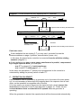
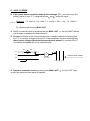
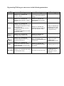
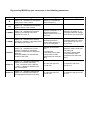
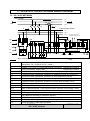
ALPES TECHNOLOGIES USER’S MANUAL ALPISTATIC CAPACITOR BANK WITH ALPTEC11-ST CONTROLLER Protection – Connection Commissioning Maintenance Réf :2007-ST-02-ANG CONTENTS I - PROTECTION - CONNECTIONS A - PROTECTION 4 B - CONNECTIONS 1) Power circuit 2) Auxiliary circuits 4 4 4 C - OPERATION ON GENSET 5 II - OPERATIONS AND INSPECTIONS TO BE PERFORMED AT THE COMMISSIONING A - BEFORE APPLYING POWER 7 B - APPLY POWER 8 III - MAINTENANCE 9 IV - DESCRIPTION 10 V- OF ALPTEC11-ST CONTROLLER FRONT PANEL ALPISTATIC CAPACITOR BANK WIRING DIAGRAM A - 220 / 240V NETWORK 13 B - 380 / 415V NETWORK 14 C - NETWORK > 415V AND ABOVE OR EGAL AT 690V 15 VI - APPENDICES A - MANUAL MODE OPERATION 14 B - MEANING OF ALARM MESSAGES 15 C - REQUIRED COS SETTING – KEYPAD LOCK - MODIFICATION OF C.T SETTING 18 I – PROTECTION - CONNECTIONS A - PROTECTION For capacitor banks which do not have a factory-fitted general protection system, a protective device must be fitted at the head of the power cable: - either a circuit breaker: thermal relay: set between 1.3 times the nominal current of the bank magnetic relay: set between 6 and 8 times the nominal current of the bank - or a fuse-switch, type gG, rated between 1.4 and 1.6 times the nominal current of the bank B - CONNECTIONS 1) Power circuit The capacitor and its accessories require power cables with a minimum rating of: I = 1.3 times the nominal current of the bank When calculating the cross-section it is also essential to take account of the usual cable-related coefficients (type, length, method of fitting, etc.). For ALPISTATIC units, the phase order L1 - L2 - L3 marked on the capacitor bank busbars must be respected for the connection of the power cables. Nota: earthing of the capacitor bank must be done by a cable with appropriate crosssection according to the updated standards. 2) Auxiliary circuits For correct operation of the power factor controller, a current transformer must be connected to ALPISTATIC units. It must be fitted on phase L3 of the unit to be compensated, upline from all receivers and the capacitor bank. The current transformer secondary must be connected on the auxiliary terminal block, marked S1 and S2 (see diagram below). Current Transformer characteristics: primary : adapted to the current line of the electrical general network secondary : 5 A minimum power: 10 VA class: 1 Diagram 1: Current transformer only supplying the P.F controller Network P1 P2 C.T. S1 load S2 phase L3 of installation lfll’l'installaT.C.on Capacitor bank auxiliary terminal block S1 S2 Diagram 2: Current transformer already supplying an ammeter Network P1 P2 C.T. S1 Load d S2 AA phase L3 of installation l'installaT.C.on ammeter Capacitor bank auxiliary terminal block S1 S2 Particular cases: If the installation has an existing C.T you may use it, provided it meets the recommendations on page 4 (position, characteristics, power, etc.). In this case, the power factor controller is connected in series with the existing ammeter (diagram 2). If the installation has two or more power transformers in parallel, compensated by a single capacitor bank, you must plan: - one C.T on phase L3 of each transformer - one overall C.T, adding type 5 + 5 ... / 5 A In this case, the equivalent C.T primary to be programmed in the controller is calculated by adding the primary values of each C.T. C – OPERATION ON GENSET If the installation can be powered by a generator unit in the event of a mains power cut, it is not necessary to disconnect the capacitor bank: the response time is maxi 40ms, so the operation is compatible with a GenSet. If, for any reason you want to disconnect the capacitor bank, simply remove the shunt between terminals G and E (see diagrams on pages 12, 13 and 14) and connect between them a contact which is opened when the generator is operating. When the generator is started, the capacitor bank will be disconnected automatically. II - OPERATIONS AND INSPECTIONS TO BE PERFORMED AT THE COMMISSIONING OF THE ALPISTATIC CAPACITOR BANK A – BEFORE APPLYING POWER Check the protective device settings and the power cable connections (page 4). Check that the current transformer is located on phase L3 of the main installation, upline from all receivers to be compensated and the capacitor bank (see diagram 3 below) Diagram 1 Diagram 2 Diagram 3 C.T C.T receivers C.T receivers receivers Ventilation Install the capacitor bank in electrical room properly ventilated * temperature maxi : 40° C and average over 24 h : 35°C Ventilation of the capacitor bank is made by an airflow * entry by the bottom (ventilation area on front door and back - sides) * output by the top (ventilation area on front door and back - sides) Make sure these ventilation areas have a clearance distance at least 100mm from any obstacle (wall, electrical enclosure… Make the airflow is sufficient by removing any obstacle from air input and output Make sure the capacitor bank is installed in a dry and non dusty electrical room B – APPLY POWER If the power factor controller displays the message “Ct”, you must enter the primary value of your C.T, using the arrows and : enter this value (Examples : T.C. 800/5 A : P01 = 800 ; T.C. 1000/5 A : P01 = 1.00 ; T.C. 1250/5 A : P01 = 1.25) To validate press the key MAN / AUT the led “MAN” flashes Switch to manual mode by pressing the key MAN / AUT and all steps connected are disconnected Check the location of the current transformer: a simple method of checking that the C.T is correctly located on phase L3 of the installation involves checking that there is zero voltage difference between network phase L3, on which the C.T is installed, and phase L3 of the capacitor bank. P1 L3 P2 C.T L2 V L1 U=0V network Capacitor bank busbar L3 L2 Switch to automatic mode by pressing key MAN / AUT on and the capacitor bank starts to operate. L1 the led “AUT” light- III - MAINTENANCE When conducting inspection or maintenance operations, it is essential to comply with applicable safety standards. Supervision must be done by an approved person. Before accessing any parts under voltage: 1) open the fuse-switch on the auxiliary circuits (ref. F1 – F2 – F3 – F4 on pages 12, 13 and 14) 2) open the circuit breaker, switch or cut-off on the power circuit. The capacitors are fitted with discharge resistors which reduce the residual voltage to 75V in 3 minutes (in compliance with applicable standards). Before short-circuiting the terminals and earthing the capacitors, Wait for 5 minutes Capacitors are static devices, little maintenance is required. However, we recommend performing the following checking annually: check that the equipment is clean, as accumulated dust can hamper correct ventilation and insulation. check the condition of the solid sate contactors and electronic command cards located on the side (a red led located on the card is lit if the card or the solid state contactors are faulty) check the tightness of the connections, particularly on the contactor terminals (a first checking 2 months after the commissioning must be done). remove dust and check the correct operation of the ventilation.. check the current delivered by the capacitor bank. Check the ventilation of the local where the equipment is installed (maximum temperature 40°C and an average value of 35°C during 24h must be respected). check the temperature inside the capacitor enclosure (maximum temperature 45°C and an average value of 40°C during 24h must be respected). IV - DESCRIPTION OF ALPTEC11-ST FRONT PANEL A Indicator lit : inductive network G Indicators lit: operation in manual mode B Indicator lit : capacitive network H Indicator lit : a programmed alarm has been memorised K Indicator lit : values displayed on screen D must be x 1000 I MAN/AUT key : switch from manual to automati mode M Indicator lit :values displayed on screen D must be x 1000000 J Parameter selection or modification key (increase ) C Digital display of instantaneous cos alarm messages L Parameter selection or modification key (decrease ) and D Digital display of all other parameters N MODE key: setting of the parameters or scrollin from functions V to SET cos E Led lit: indicates the steps connected O FUN key: to scroll functions from W to STEP cn F Led lit: operation in automatic mode A E B K M C F G H D O I J N L By pressing FUN key you can access to the following parameters: LED Meaning Pressing ↓ Pressing ↑ V Display « D » indicates the network voltage Display “D” indicates the highest memorised network voltage A Display « D » indicates the current value of phase L3 of the network Display “D” indicates the highest memorised current on phase L3. Δ Kvar Display « D » indicates the required reactive power to reach the set point cosφ (kvar if K is lit, MVAR if M is lit). * led IND lit indicates a lack of reactive power * led CAP lit indicates an excess of reactive power. Display “D” indicates the required number of steps to reach the set point cosφ WEEK P.F. Display « D » indicates the average weekly power factor. Display “D” indicates the actual power factor. Display « D » indicates the current capacitor overload (%) caused by harmonics. Display “D” indicates the max. % overload of the capacitor memorised and due to harmonics. Display “D” indicates the number of exceeds compare to the programmed threshold TEMP° Display « D » indicates the temperature inside the cubicle (temperature sensor at the back of the controller) Display “D” indicates the max. temperature recorded in the cubicle Measuring units °C or °F SET COSφ Display « D » indicates the value of the set point cos φ Decrease the set point cosφ Increase the set point cosφ (if letter C is flashing, the cosφ is capacitive CURR¨% Display “D” indicates the multiplying factor of the smallest step to reach the set point cos φ By pressing MODE key you can access to the following parameters: Led Meaning W Display « D » indicates the threephase active power of the network VA Display « D » indicates the threephase apparent power of the network Pressing ↓ Pressing ↑ Display “D” indicates the network frequency V HARM Display « D » indicates the harmonic voltage (%) according to the rank diplayed on screen “C” Selection on display “C” of decreasing harmonic voltage ranks from 31 to 2 and ThdU. Selection on display “C” of increasing harmonic voltage ranks from 2 to 31 and ThdU. I HARM Display « D » indicates the harmonic current (%) of phase L3 according to the rank diplayed on screen “C” Selection on display “C” of decreasing harmonic current ranks (phase L3) from 31 to 2 and ThdI. Selection on display “C” of increasing harmonic current ranks (phase L3) from 2 to 31 and ThdI. Selection of the events from: Selection of the events from: EVENTS Display « D » indicates the current capacitor overload (%) caused by harmonics compare to the authorised threshold. Alternately display “D” indicates the duration of the event. STEP var Display « C » indicates selected step. Display “D” indicates alternately: * UAr: real power of the capacitor * PErC: % difference between real and nominal power To select the step from S.12 to S.01 To select the step from S.01to S.12 STEP cnt Display « C » indicates selected step. Display “D” indicates the number of connection/disconnection of the step To select the step from S.12 to S.01 To select the step from S.01 to S.12 E-0 (today) to E-6 (6 days before) and E-HI (maximum value memorised over the 6 last days) E-0 (today) to E-6 (6 days before) and E-HI (maximum value memorised over the 6 last days) V – ALPISTATIC CAPACITOR BANK WIRING DIAGRAM A - 220 / 240V NETWORK User‟s busbar L1 P2 load D C.T. S2 L2 P1 L3 S1 network J E Capacitor bank busbar L1 L2 L3 FU To 400V capacitor bank auxiliary circuit C.C F3 F1 K F4 F2 S2 L GE S1 L1 L2 L3 TR1 Capacitor bank termi R Co 1 2 3.......6 7 8 …. 11 C S2 S1 : user‟s connection C.T J E D F1 F2 F3 F4 FU K TR1 Co R L S1, S2 G, E C.C L1 L2 L3 RS232 RS485 Alptec11-ST controller termina block Primary: depending on installation current supplied by customer Secondary: 5 A - minimum 10 VA – class 1 Cables 2 × 2.5 mm² for current transformer connection supplied by customer Three-pole battery supply cable supplied by customer Main three-pole circuit breaker (capacitor bank output) supplied by customer Protection fuses, type aM 2A: protection of measuring circuit ALPTEC11-ST Protection fuses, type aM 4A: protection of auto-transformer primary Protection fuses, type gG 4A: protection of capacitor bank auxiliary circuit Protection fuses, type aM 2A: protection of power factor auxiliary circuit HRC fuses, type gG, size .................. rating.................. Solid state contactor Auto-Transformer 230V / 400V for capacitor bank auxiliary supply (400VA) Capacitor Discharge resistors Anti Harmonic reactors (on customer request) C.T secondary connection terminal block Terminal block for capacitor bank bypass during GenSet operation Command card for solid state contactor ALPISTATIC capacitor bank 220 / 240V network 15 17 0 230 ALPTEC11-ST V – ALPISTATIC CAPACITOR BANK WIRING DIAGRAM B - 380 / 415V NETWORK User‟s busbar L1 P2 load D C.T. S2 L2 P1 L3 S1 network J E Capacitor bank busbar L1 L2 L3 FU To 400V capacitor bank auxiliary circuit C.C F4 F1 K S2 L S1 L1 L2 L3 Capacitor bank termina TR1 R Co 1 2 3.......6 7 8 …. 11 C S2 S1 : user‟s connection C.T J E D F1 F2 F3 F4 FU K TR1 Co R L S1, S2 G, E C.C GE F3 F2 L1 L2 L3 RS232 RS485 Alptec11-ST controller terminals block Primary: depending on installation current supplied by customer Secondary: 5 A - minimum 10 VA – class 1 Cables 2 × 2.5 mm² for current transformer connection supplied by customer Three-pole battery supply cable supplied by customer Main three-pole circuit breaker (capacitor bank output) supplied by customer Protection fuses, type aM 2A: protection of measuring circuit ALPTEC11-ST Protection fuses, type aM 4A: protection of auto-transformer primary Protection fuses, type gG 4A: protection of capacitor bank auxiliary circuit Protection fuses, type aM 2A: protection of power factor auxiliary circuit HRC fuses, type gG, size .................. rating.................. Solid state contactor Auto-Transformer 400V / 230V for power factor auxiliary circuit supply (75VA) Capacitor Discharge resistors Anti Harmonic reactors (on customer request) C.T secondary connection terminal block Terminal block for capacitor bank bypass during GenSet operation Command card for solid state contactor ALPISTATIC capacitor bank 380 / 415V network 15 17 0 230 ALPTEC11-ST V – ALPISTATIC CAPACITOR BANK WIRING DIAGRAM C – NETWORK > 415V or <= 690V User‟s busbar L1 P2 load D C.T. S2 L2 P1 L3 S1 network J E Capacitor bank busbar L1 L2 L3 FU To 400V capacitor bank auxiliary circuit C.C F4 F1 K S2 L S1 L1 L2 L3 Capacitor bank termina TR1 R Co C.T J E D F1 F2 F3 F4 FU K TR1 Co R L S1, S2 G, E C.C GE F3 F2 1 2 3.......6 7 8 …. 11 C S2 S1 L1 L2 L3 RS232 RS485 15 17 0 230 Alptec11-ST controller terminals block Primary: depending on installation current supplied by customer Secondary: 5 A - minimum 10 VA – class 1 Cables 2 × 2.5 mm² for current transformer connection supplied by customer Three-pole battery supply cable supplied by customer Main three-pole circuit breaker (capacitor bank output) supplied by customer Protection fuses, type aM 2A: protection of measuring circuit ALPTEC11-ST Protection fuses, type aM 4A: protection of auto-transformer primary Protection fuses, type gG 4A: protection of capacitor bank auxiliary circuit Protection fuses, type aM 2A: protection of power factor auxiliary circuit HRC fuses, type gG, size .................. rating.................. Solid state contactor Auto-Transformer …/ 230V and 400V for power factor auxiliary circuit supply and auxiliary capacitor bank supply (400VA) Capacitor Discharge resistors Anti Harmonic reactors (on customer request) C.T secondary connection terminal block Terminal block for capacitor bank bypass during GenSet operation Command card for solid state contactor ALPISTATIC capacitor bank network>415V or <= 690V ALPTEC11-ST VI - APPENDICES A - MANUAL MODE OPERATION If you wish you may operate your capacitor bank in manual or "forced" mode. To achieve this, proceed as follows: Enter manual mode by pressing the MAN / AUT key. The "MAN" indicator will be lit. All the steps under voltage are disconnected. Press the arrows and as many times as necessary to select the step that you wish to connect or disconnect: the selection is obtained as soon as the corresponding led flashes. Press the "MODE" key to validate this selection. Repeat the operation for each step you wish to connect or disconnect. Note: In manual mode, the selected steps remain connected. VI - APPENDICES B – MEANING OF ALARM MESSAGES Alarm messages may be displayed on the ALPTEC11-ST controller during commissioning or use of the capacitor bank. The meaning of the messages is as follows: Message A01: undercompensation All the capacitors are connected but the cos is less than the cos set point. - check the cos set point value setup. - if the error persists, your capacitor bank is undersized, you should add reactive power to your installation. The required „kvar‟ value can be displayed with the led “ kvar” (marked F on page 9) Message A02: overcompensation All the capacitors are disconnected and the cos is above the set point value. - check the cos set point value setup. - the installation may have fixed capacitors - the installation may be unloaded - check the position of the current transformer (diagrams page 6 and 7). - if the error persists (with the installation under load), call the manufacturer Message A03: current too low The line current is 2,5% lower than the C.T primary current setting. - check that the primary of your C.T is suitable for the mains line current. - check your C.T. is not short-circuited - check the current circuit is properly “conducting” - with loads connected this message will disappear Message A04: current too high The current exceeds the C.T primary current setting by 20%. - check the C.T primary value set in the controller. - check that the primary of your C.T is suitable for the mains line current. - if the secondary current is too high (primary too low) the controller may be damaged. Message A05: voltage too low The measured voltage is 15% lower than network voltage. - low voltage will disconnect the steps. Message A06 : voltage too high The measured voltage is 10% above the network voltage. - high voltage will disconnect the steps. Message A07 : capacitor overload The capacitor bank is stressed by important harmonic perturbations, all the steps are disconnected: please call the manufacturer Message A08 : over temperature Temperature inside the capacitor bank is too high, report to the ventilation conditions of the electrical room (page 6). Message A09 : no voltage release Voltage failure duration is more than 8ms. All the steps are disconnected Message A10 : faulty steps - Look for the faulty step(s) Proceed to their replacement Message A11 : exceeding of programmed harmonic threshold (ThdU or ThdI) Possibilty to disconnect the steps and remote this event Message E.AL : programmable complementary alarm For remote temperature probe or a econd set point coc phi, activated by dry contact. Nota: following 11 alarms: A01 to A08 and A10 to A11 can be remoted by dry contacts.. For more information, please consult our technical department C – REQUIRED COS SETTING * press the key MODE several times, until the led “SET COS ” indicator on the front panel lit. * using the arrow keys and , set the cos * in the factory we set the cos to the target value. set point to 0.96 inductive D – KEYPAD LOCK Locking: It is possible to lock the keypad to avoid any modification of the parameters: Keep pressed MODE key, press 3 times key and 2 times key : then release MODE key and “Loc” will appears on the screen Unlocking: Keep pressed MODE key, press 3 times key and 2 times key : then release MODE key and “UnL” will appears on the screen E – MODIFICATION OF PRIMARY C.T SETTING - Switch the controller in manual mode using the key “MAN / AUT” - Keep pressed MODE key until “SET” is displayed on the screen - Release MODE key, pressed key MAN / AUT, “P01” is displayed - Using keys P01=1.25) enter this value (example: C.T 800/5A – P01=800 ; C.T 1250/5A – - Press several times MAN / AUT key until the display of the count down - Switch to automatic mode by MAN / AUT key Note: any modifications of the power factor controller parameters (except parameter P01) will cancel the manufacturer warranty on the complete equipment. NOTES ALPES TECHNOLOGIES P.A.E. Les Glaisins 7 rue des Bouvières B.P. 332 74 943 ANNECY-LE-VIEUX cedex FRANCE Téléphone : + 33.4.50.64.05.13 FAX : + 33.4.50.64.04.37 Site : www.alpestechnologies.com E-mail : [email protected]