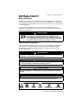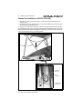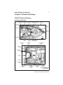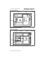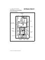
1
The information in this Owner’s Manual Supplement relates to 2000 & 2001
2302 DX/LX, 2352 DX/LX 2359, DX/LX Bayliner Trophy Fishing Boats.
Hull Identification Number___________________________________________
Engine Serial Number _______________________________________________
Hull Identification Number:
The Hull Identification Number
(HIN) is located on the starboard
side of the transom. Record the
HIN and the engine serial number
in the space provided above. Refer
to the HIN for any correspondence
or orders.
HULL
IDENTIFICATION
NUMBER
HIN LOCATION (TYPICAL)
TRANSOM
© 2000 Bayliner Technical Publications. All rights reserved.
No part of this publication may be reproduced, stored in any retrieval system, or transmitted
in any form by any means, electronic, mechanical, photocopying, recording or otherwise,
without prior written permission of Bayliner. Printed in the United States of America.
Changes
The material in this document is for information only and is subject to change without notice.
While reasonable efforts have been made in the preparation of this document to assure its accuracy, Bayliner assumes no liability resulting from errors or omissions in this document, or
from the use of information contained herein.
Bayliner reserves the right to make changes in the product design, specifications, and equipment at any time without notice or obligation.
Illustrations and/or photos may show optional equipment.
Contents
Chapter 1: Welcome Aboard!
1
Dealer Service
1
Boating Experience
1
Qualified Maintenance
2
Special Care For Moored Boats
2
Engine & Accessories
Guidelines
3
Safety Standards
3
Hazard Warning Symbols
Chapter 2: Specifications &
Features
4
2302FP
10 2352 FN Features and Systems
16 2359 FB Features and Systems
29 Fuel System
29 Fuel Fills and Vents
29 Fuel Filters
29 Oil Injection System (2302 FP)
30 Trim Tabs
30 Power Trim and Tilt
31 Navigation and
Communication Equipment
31 VHF Radio (LX only)
31 Compass
31 Lighting
31
32
32
32
Navigation Lights
AM/FM Cassette Stereo
Alcohol Stove
Refrigerator (2359 FB LX)
32 Bilge Pumps
33 Bilge Pump Testing
33 Checking for clogging debris:
33 Autofloat Switches
34 Fresh Water System
34 Water Pump (2359FB LX)
Chapter 3: General Systems
23 Electrical System
24 12-Volt DC Electrical System
24
24
24
25
Fuses and Circuit Breakers
Batteries
Battery Switch (2359 FB)
Battery Charger (2359 FB LX)
26 AC Electrical System (2359 FB)
26 Connecting to Shore Power
28 Propulsion
28 Engine
28 Bilge Blower
34 Raw Water System
34 Seacocks
35 Head System
35 Portable Head
35 Marine Head with Holding Tank
(LX Only)
35 Macerator (LX Option)
36 Fishwells
36 Bait Well System
37 Recirculation System
(2352 FN, 2302 FP)
38 Canvas Top Installation
(2302 FP, 2352 FN)
Chapter 4: Electrical Routings
39 2302 FP Electrical Routings
39 Deck Harness Routing
40 Hull Harness Routing
40 2352 FN Electrical Routings
40 Hull Harness Routing
41 Deck Harness Routing
42 2359 FB Electrical Routings
42
43
44
44
45
45
Hull Harness Routing
Battery Cable Routings
Forward Deck Harness Routing
Mid Deck Harness Routing
Aft Deck
AC Panel Routings
Chapter 5: Wiring Diagrams
46 2302 FP Electrical System
47 2352 FN Electrical System
48 2359 FB AC Electrical System
49 2359 FB DC Electrical System
Appendix A: Limited Warranty
50 What Is Not Covered
50 Other Limitations
50 Your Obligation
1
Chapter 1: Welcome Aboard!
Welcome aboard! This owner’s manual supplement provides specific information
about your boat that is not covered in the owner’s manual. Please study the owner’s
manual and this supplement carefully, paying particular attention to Appendix A:
Limited Warranty in this supplement. Keep the owner’s manual and this supplement on your boat in a secure, yet readily available place.
Dealer Service
Make sure you receive a full explanation of all systems from the selling dealer
before taking delivery of your boat. Your selling dealer is your key to service. If
you experience any problems with your new boat, immediately contact the selling
dealer. If for any reason your selling dealer is unable to help, you can call us direct
on our customer service hotline: 360-435-8957 or send us a FAX: 360-403-4235.
Boating Experience
If this is your first boat or if you are changing to a type of boat you are not familiar
with, for your own comfort and safety, you must obtain handling and operating
experience before assuming command of the boat.
Take one of the boating safety classes offered by the U.S. Power Squadrons or the
U.S. Coast Guard Auxiliary. For more course information, including dates and
locations of upcoming classes, contact the organizations directly:
• U.S. Power Squadrons: 1-888-FOR-USPS (1-888-367-8777) or on the Internet
at: http://www.usps.org
• U.S. Coast Guard Auxiliary: 1-800-368-5647 or on the Internet
at: http://www.cgaux.org
Outside the United States, your selling dealer, national sailing federation or local
yacht club can advise you of local sea schools or competent instructors.
!
WA R N I N G !
CONTROL HAZARD! A qualified operator must be in control of the boat at all
times. DO NOT operate your boat while under the influence of alcohol or drugs.
Qualified Maintenance
Failure to maintain your boat’s systems as designed could violate the laws in your
jurisdiction and will expose you and other people to the danger of bodily injury or
accidental death. Follow the instructions provided in the owner’s manual, this
owner's manual supplement, the engine owner’s manual and all accessory instruction sheets/manuals included in your boat’s owner’s packet.
23’ Trophy • Owner’s Manual Supplement
2
Chapter 1: Welcome Aboard!
!
WA R N I N G !
To maintain the integrity and safety of your boat, only qualified personnel
should perform maintenance on, or in any way modify: The steering system,
propulsion system, engine control system, fuel system, environmental control
system, electrical system or navigational system.
Special Care For Moored Boats
If moored in saltwater or fresh water, your boat will collect marine growth on its
hull bottom. This will detract from the boat’s beauty, greatly affect its performance
and may damage the gelcoat. There are two methods of slowing marine growth:
• Periodically haul the boat out of the water and scrub the hull bottom with a bristle
brush and a solution of soap and water.
• Paint the hull below the waterline with a good grade of anti-fouling paint.
NOTICE
To help seal the hull bottom and reduce the possibility of gelcoat blistering on
moored boats, Bayliner recommends the application of an epoxy barrier coating, such as Interlux, Interprotect 2000E/2001E. The barrier coating should be
covered with several coats of anti-fouling paint.
Many states regulate the chemical content of bottom paints in order to meet
environmental standards. Check with your local Bayliner dealer about recommended bottom paints, and about the laws in effect in your area.
Engine & Accessories Guidelines
Your boat’s engine and accessories were selected to provide optimum performance
and service. Installing different engines or accessories will cause unwanted handling characteristics. Should you choose to install different engines or add accessories that will affect the boat’s running trim, have an experienced marine technician
perform a safety inspection and handling test before operating your boat again.
Please be advised that certain modifications to your boat can result in cancellation of your warranty protection. Always check with your dealer before making any modifications to your boat.
The engine and accessories installed on your boat come with their own operation
and maintenance manuals. Read and understand these manuals before operating the
engine and accessories.
NOTICE
When storing your boat refer to your engine’s operation and maintenance manuals.
23’ Trophy • Owner’s Manual Supplement
Chapter 1: Welcome Aboard!
3
Safety Standards
Your boat’s mechanical and electrical systems were designed to meet safety standards in effect at the time it was built. Some of these standards were mandated by
law; all of them were designed to insure your safety, and the safety of other people,
vessels and property.
In addition to this supplement, read the owner’s manual and all accessory
instruction sheets included in your owner’s packet for important safety standards
and hazard information.
!
D A N G EDANGER
R!
PERSONAL SAFETY HAZARD! DO NOT allow anyone to ride on
parts of the boat not designated for such use. Sitting on seat
backs, lounging on the forward deck, bow riding, gunwale riding
or occupying the transom platform while underway is especially
hazardous and WILL cause personal injury or death.
Hazard Warning Symbols
The hazard warning symbols shown below are used throughout this supplement
to call attention to potentially dangerous situations which will lead to either
personal injury or product damage. Read these warnings carefully and follow
all safety instructions.
!
D A N G EDANGER
R!
This symbol alerts you to immediate hazards which WILL cause severe personal injury or death if the warning is ignored.
!
WA R N I N G !
This symbol alerts you to hazards or unsafe practices which COULD result in
severe personal injury or death if the warning is ignored.
!
CAUTION!
This symbol alerts you to hazards or unsafe practices which COULD result in
minor personal injury or cause product or property damage if the warning is
ignored.
NOTICE
This symbol calls attention to installation, operation or maintenance information, which is important to proper operation but is not hazard related.
HOT
HAZARD!
EXPLOSION
HAZARD!
ELECTRICAL
HAZARD!
OPEN FLAME
HAZARD!
PERSONAL INJURY
& FALLING HAZARD!
ROTATING
PROPELLER HAZARD!
23’ Trophy • Owner’s Manual Supplement
4
Chapter 2: Specifications & Features
2302FP
Dimensions and Tank Capacities
Overall
Length
Bridge
Clearance
Beam
Draft
(Drive Up)
Water
Capacity
Fuel Tank
Capacity
23’5"
7’11"
8’5"
1’7"
8 gal.
101 gal.
Layout View
coaming caps
jump fish well
locker
seat
step
storage
galley
storage
cooler bucket
seat
table
storage
storage
fuel
fill
jump
seat
bait
live
well
fish well
locker
coaming caps
step
bucket
seat
rope
locker
storage
storage
Hull Exterior Drains & Hardware
BILGE PUMP
DRAIN
FISHWELL
DRAIN
ANCHOR
LOCKER
DRAIN
BAITWELL
DECK
DRAIN
DRAIN
WATER TANK
VENT
WASTE TANK
VENT (OPTION)
BOW
EYE
DECK
DRAIN
23’ Trophy • Owner’s Manual Supplement
SINK
DRAIN
FISHWELL
DRAIN
Chapter 2: Specifications & Features
5
Transom Hardware
TRANSOM
STERN EYE
(TYPICAL)
GARBOARD
DRAIN
DECK DRAIN
(TYPICAL)
TRIM TAB
(TYPICAL)
Foredeck Hardware
HORN
ANCHOR ANCHOR
STORAGE ROLLER
BOW
CLEAT
NAV. LIGHT
(TYPICAL)
FWD.
STBD.
23’ Trophy • Owner’s Manual Supplement
6
Chapter 2: Specifications & Features
Helm Dash
TACHOMETER VOLTMETER
FUEL
SPEEDOMETER
ACCESSORY
SWITCHES
ACCESSORY
SWITCHES
STEERING
WHEEL
CIRCUIT
BREAKERS
Cockpit Features
TRIM TAB
PUMP ACCESS
FUEL FILL
LOCATION
ROD
HOLDERS
HAWSE
PIPE
(TYPICAL)
ROD
HOLDER
(TYPICAL)
FISHWELL
(TYPICAL)
23’ Trophy • Owner’s Manual Supplement
ENGINE
BATTERY
ACCESS
Chapter 2: Specifications & Features
7
Warning Labels
FUEL FILL &
FUELING WARNING
LABELS
STBD.
FWD.
EMERGENCY
SHUTDOWN
WARNING LABEL
TRIM TAB
WARNING
LABEL
AFT
CAPACITY
WARNING
LABEL
Bilge Pump Routing
FWD. BILGE PUMP ROUTING
BILGE PUMP &
FLOAT SWITCH
AFT BILGE PUMP ROUTING
BILGE PUMP &
FLOAT SWITCH
THRU-HULL
FWD.
STBD.
THRUHULL
PORT
AFT
23’ Trophy • Owner’s Manual Supplement
8
Chapter 2: Specifications & Features
Head & Waste Tank System (LX Only)
HEAD SYSTEM ROUTING
VENTED LOOP
PORT
FWD.
SEA WATER
PICK-UP
TOILET
(OPTIONAL) MACERATOR ROUTING
TO PUMP- OUT
FITTING IN DECK
PORT DECK
MACERATOR
WASTE PUMPOUT FITTING
HOLDING
TANK
FWD.
SEA
WATER
PICK-UP
FWD.
PORT
TOILET
23’ Trophy • Owner’s Manual Supplement
Chapter 2: Specifications & Features
9
Fuel System
VIEW OF AFT DECK
STBD. AFT
FUEL FILL
DECK
AFT
FUEL
TANK
STBD.
TO
MOTOR
TO VENT
HOSE
FUEL
FILL
Freshwater System
FRESHWATER ROUTING
WATER
WATER FILL TO GALLEY
TANK
ON DECK
SINK
PORT
WATER FILL LOCATION
WATER TANK
FITTING
PORT SIDE
OF DECK
FWD.
FWD.
23’ Trophy • Owner’s Manual Supplement
10
Chapter 2: Specifications & Features
2352 FN Features and Systems
Dimensions and Tank Capacities
Overall
Length
Bridge
Clearance
Beam
Draft
(Drive Up)
Water
Capacity
Fuel Tank
Capacity
23’5"
7’11"
8’5"
1’7"
8 gal.
101 gal.
Layout View
coaming caps
removable
fish well
locker
jump seat
step
galley
storage
storage
cooler
bucket
seat
convertable
table
storage
engine
compartment
bait
live
well
removable
fish locker
well
jump seat
coaming caps
head
bucket
seat
storage
step
fuel
fill
storage
Hull Exterior Hardware
BILGE PUMP
DRAIN
FISHWELL
DRAIN
ANCHOR
LOCKER
DRAIN
BAITWELL
DRAIN
DECK
DRAIN
WATER TANK
VENT
WASTE TANK
VENT (OPTION)
BOW
EYE
SINK
DRAIN
23’ Trophy • Owner’s Manual Supplement
BILGE PUMP
DRAIN
FISHWELL
DRAIN
Chapter 2: Specifications & Features
11
Transom Hardware
TRANSOM
DECK DRAIN
(TYPICAL)
GARBOARD
DRAIN
STERN EYE
(TYPICAL)
TRIM TAB
(TYPICAL)
Foredeck Hardware
HORN
ANCHOR
STORAGE
ANCHOR
ROLLER
BOW
CLEAT
NAV. LIGHT
(TYPICAL)
FWD.
STBD.
23’ Trophy • Owner’s Manual Supplement
12
Chapter 2: Specifications & Features
Helm Dash
TACHOMETER VOLTMETER FUEL
SPEEDOMETER
ACCESSORY
SWITCHES
ACCESSORY
SWITCHES
STEERING
WHEEL
CIRCUIT
BREAKERS
Cockpit Features
BAITWELL
ENGINE
ACCESS
FISHWELL
(TYPICAL)
ROD HOLDER
(TYPICAL)
HAWSE
PIPE
PORT
AFT
23’ Trophy • Owner’s Manual Supplement
Chapter 2: Specifications & Features
13
Warning Labels
STB
D.
FUEL FILL & FUELING
WARNING LABELS
AFT
FOREDECK
WARNING
LABEL
FWD.
TRIM TAB
WARNING
LABEL
CAPACITY
WARNING
LABEL
EMERGENCY
SHUTDOWN
WARNING
LABEL
STBD.
Bilge Pump Routing
FWD. BILGE PUMP ROUTING
BILGE PUMP &
FLOAT SWITCH
AFT BILGE PUMP ROUTING
THRUHULL
STBD.
FWD.
THRUHULL
BILGE PUMP
FLOAT SWITCH
AFT
PORT
23’ Trophy • Owner’s Manual Supplement
14
Chapter 2: Specifications & Features
Fuel System
TO FUEL
FITTING ON
STBD. DECK
TO FUEL
VENT IN
HULL
FUEL FILL ON
STBD. DECK
FUEL LINE
TO ENGINE
AFT
FWD.
ENGINE
COMPARTMENT
STBD.
FUEL
TANK
Freshwater System
FRESHWATER ROUTING
WATER
WATER FILL TO GALLEY
TANK
ON DECK
SINK
PORT
WATER FILL LOCATION
WATER TANK
FITTING
FWD.
FWD.
23’ Trophy • Owner’s Manual Supplement
PORT SIDE
OF DECK
Chapter 2: Specifications & Features
15
Head & Waste Tank System (LX Only)
VENTED
LOOP
PORT
FWD.
TOILET
SEA WATER
PICK-UP
(OPTIONAL) MACERATOR ROUTING
TO PUMP- OUT
FITTING IN DECK
MACERATOR
HOLDING
TANK
PORT
SEA
WATER
PICK-UP
TOILET
FWD.
TO WASTE PUMPOUT FITTING
WASTE
TANK
PORT DECK
HOSE TO
WASTE
TANK
WASTE PUMPOUT FITTING
FWD.
PORT
FWD.
TOILET
23’ Trophy • Owner’s Manual Supplement
16
Chapter 2: Specifications & Features
2359 FB Features and Systems
Dimensions and Tank Capacities
Overall
Length
Bridge
Clearance
Beam
Draft
(Drive Up)
Water
Capacity
Fuel Tank
Capacity
23’5"
7’4"
8’5"
1’7"
20 gal.
87 gal.
Layout View
coaming cap
removable
jumpseat
fishwell
dinette area
head
baitwell
sink
removable
jumpseat
fishwell
stove
storage
helm
area
coaming cap
Hull Exterior Hardware
AFT BILGE
PUMP DRAIN
FISH
WELL
FUEL
VENT
SINK
DRAIN
FWD. BILGE
PUMP DRAIN
ROPE
LOCKER
DRAIN
DECK
DRAINS
BAITWELL
DRAIN
MIDSHIP
DRAIN
WASTE TANK VENT
(OPTION)
BOW
EYE
23’ Trophy • Owner’s Manual Supplement
FISHWELL
DRAIN
Chapter 2: Specifications & Features
17
Transom Hardware
MIDSHIP STORAGE
DRAIN
TRANSOM
STERN EYE
(TYPICAL)
GARBOARD
DRAIN
TRIM TAB
(TYPICAL)
Foredeck Hardware
DECK CLEAT
(TYPICAL)
BOW
HATCH
FWD.
PORT
BOW
CLEAT
ANCHOR
ROLLER
NAV. LIGHT
(TYPICAL)
DECK
PIPE
23’ Trophy • Owner’s Manual Supplement
18
Chapter 2: Specifications & Features
Helm
ACCESSORY SWITCHES
TROPHY
PUMPS
LIGHTS
ACCY
PORT
WIPER
STBD.
WIPER
COCKPIT
NAV.
ANCHOR
STBD.
FISH
WELL
PORT
FISH
WELL
BAIT
WELL
FWD.
BILGE
AFT
BILGE
HORN
COMPASS
HELM
TACHOMETER
TEMPERATURE
DASH PANEL
OIL
SPEEDOMETER
BLOWER
SWITCH
IGNITION
23’ Trophy • Owner’s Manual Supplement
FUEL
VOLTMETER
Chapter 2: Specifications & Features
19
Warning Labels
“DO NOT BOARD
POTABLE WATER
FOREDECK” WARNING
LABEL
LABEL
FUEL FILL &
FUELING WARNINGS
STBD.
AFT
Fuel System
FUEL TANK
VENT
TO FUEL FITTING
ON DECK
AFT CABIN
ENTRY DOOR
AFT
FUEL
TANK
STB
D.
.
BD
ST
TO
ENGINE
STBD.
DECK
FUEL FILL
FITTING
AFT
23’ Trophy • Owner’s Manual Supplement
20
Chapter 2: Specifications & Features
Bilge Pumps
AFT BILGE PUMP ROUTING
FWD. BILGE PUMP
& FLOAT SWITCH
FWD. BILGE PUMP ROUTING
FWD. BILGE PUMP
& FLOAT SWITCH
THRU-HULL
THRU-HULL
Baitwell System
D
A
B
A.
B.
C.
D.
E.
F.
G.
H.
I.
TANK
OVERFLOW DRAIN
AERATOR WAND
AERATOR
BAITWELL PUMP
RAW WATER FILTER
SEAWATER PICKUP
TO HULLSIDE DRAIN
LED LIGHT
B
C
E
F
H
G
23’ Trophy • Owner’s Manual Supplement
I
C
Chapter 2: Specifications & Features
21
Freshwater System
BREAKAWAY VIEW OF PORT HULLSIDE
PORT SIDE
OF DECK
FWD.
WATER TANK
VENT HOSE
HOSE TO
FITTING ON
DECK
WATER
TANK
WATER
PUMP (LX ONLY)
WATER SYSTEM ROUTING
WATER TANK
FITTING
GALLEY
SINK
AFT
WATER
TANK
WATER PUMP
(LX ONLY)
23’ Trophy • Owner’s Manual Supplement
22
Chapter 2: Specifications & Features
Head & Waste System (LX Only)
TOILET
RAW WATER
PICK UP
VENTED
LOOP
AFT
DECK
WASTE PUMPOUT FITTING
FWD.
TRANSOM
WASTE TANK SYSTEM (MACERATOR OPTION SHOWN)
WASTE TANK
LOCATION
HOSE FROM
HEAD
UNDERWATER
DISCHARGE
HOSE TO
MACERATOR
STBD.
AFT
FROM MACERATOR
TO UNDERWATER
DISCHARGE
TO WASTE PUMPOUT FITTING
MACERATOR
23’ Trophy • Owner’s Manual Supplement
Y-FITTING
23
Chapter 3: General Systems
Electrical System
Read this section and the electrical sections of the owner’s manual and all accessory manuals included in your boat owner’s packet. Electrical system drawings are
provided in Chapter 4 and Chapter 5 of this supplement.
!
D A N G EDANGER
R!
EXTREME FIRE, SHOCK & EXPLOSION HAZARD!
• To minimize the risks of fire and explosion, NEVER install knife switches or
other arcing devices in the fuel compartments.
• NEVER substitute automotive parts for marine parts. Electrical, ignition and
fuel system parts were designed and manufactured to comply with rules and
regulations that minimize risks of fire and explosion.
• DO NOT modify the electrical systems or relevant drawings.
• Only qualified personnel should install batteries and/or perform electrical system maintenance.
• Insure that all battery switches are turned OFF before performing any work
in the engine spaces.
!
WA R N I N G !
FIRE, OPEN FLAME & EXPLOSION HAZARD!
• Fuel fumes are heavier than air and will collect in the bilge areas where they
can be accidently ignited. Visually and by smell (sniff test), check the engine
and fuel compartments for fumes or accumulation of fuel. ALWAYS operate
the bilge blowers for at least four minutes prior to engine starting, electrical
system maintenance or activation of electrical devices.
• Minimize the danger of fire and explosion by not exposing batteries to open
flame or sparks. It is also important that no one smoke anywhere near
the batteries.
!
CAUTION!
SHOCK & ELECTRICAL SYSTEM DAMAGE HAZARD!
NEVER disconnect the battery cables while the engine is running since
it can cause damage to your boat’s electrical system components.
NOTICE
Electrical connections are prone to corrosion. To reduce electrical problems
caused by corrosion, keep all electrical connections clean and apply a spray-on
protectant that is designed to protect connections from corrosion.
23’ Trophy • Owner’s Manual Supplement
24
Chapter 3: General Systems
12-Volt DC Electrical System
Your boat is equipped with a 12-volt DC (direct current) system.
Fuses and Circuit Breakers
• Fuses and circuit breakers for engines and main accessory power may be on the
DC main distribution panel and on the battery switch panel (if installed).
• Electronics power is provided at the helm.
• Some equipment may have secondary fuse protection at the unit.
• Wires are color-coded to indicate which accessory each fuse services. Some
items, such as radios and bilge pumps, may be fused individually at the unit.
Autofloat switches are fused at the battery.
Batteries
The batteries supply electricity for lights, accessories and engine starting. The electrical section of Chapter 7 in the Owner’s Manual provides battery care and maintenance instructions.
Battery Switch (2359 FB)
Your boat may feature a battery switch
(2359 FB only). The battery switch is
located in the galley storage area.
Battery Switch Positions
POSITION ALL
ACTIVATES BOTH
BATTERIES
POSITION 1
“OFF”
ACTIVATES POSITION
BATTERY 1
POSITION 2
ACTIVATES
BATTERY 2
The battery switch has four (4) positions
(see photograph to the right);
• Position 1 - provides power for engine
starting and accessories from battery 1 .
Battery 1 (only) will be charged by the
engine alternator when the engine is running at high idle or faster.
• Position 2 - provides power, for engine
starting and accessories from battery 2 .
Battery 2 (only) will be charged by the
engine alternator when the engine is running at high idle or faster.
• Position ALL -if batteries are low; provides power for engine starting from
both batteries. The ALL position also
allows the charging of both batteries by
the engine alternator when the engine is
running at high idle or faster.
The battery switch should be switched to
the ”OFF” position whenever the boat is
left unoccupied for long periods of time.
HELM
FWD.
BATTERY SWITCH LOCATED
IN GALLEY STORAGE AREA
NOTICE
Since the batteries on your boat were dealer-installed, the battery switch positions listed above may vary. Make sure you’ve had a full explanation of battery
switch operation from your selling dealer.
23’ Trophy • Owner’s Manual Supplement
Chapter 3: General Systems
!
25
CAUTION!
SYSTEM DAMAGE HAZARD! NEVER disconnect battery cables or turn off
the battery switch while your engine is running as this can cause damage to your
boat’s electrical components.
Battery Charger (2359 FB LX)
Your boat may be equipped with a battery charger located in the aft port cabin.
Read and understand the battery charger instructions included in your owner’s
packet before using the charger.
• The battery charger will charge the boat’s batteries whenever the boat is plugged
into 120 volt shore power.
• For proper charging; turn the battery switch to any position except ALL.
!
CAUTION!
• The battery charging systems (alternator and battery charger) are designed
to charge conventional lead-acid batteries. Before installing gel-cell (or other
new technology) batteries, read and follow the battery charger’s operating
instructions.
• Loose battery cable connections will damage your battery charger and
your boat.
23’ Trophy • Owner’s Manual Supplement
26
Chapter 3: General Systems
AC Electrical System (2359 FB)
Your boat may come equipped with an optional AC (alternating current) system
which is energized from shore power. Shore power is supplied to your boat using a
120v/30 amp shore power receptacle.
!
D A N G EDANGER
R!
FIRE, EXPLOSION & SHOCK HAZARD!
• DO NOT alter shore power connectors and use only compatible connectors.
• Before connecting or disconnecting the shore power cord to your boat, verify
all breakers and switches on the AC master panel are turned OFF.
• To prevent shock or injury from an accidental dropping of the “hot” cord into
the water, ALWAYS attach the shore power cord to the boat inlet first; then to
the dockside connection. When disconnecting from shore power, disconnect
the shore power cord from the dockside connection first.
• NEVER leave a shore power cord connected to the dockside connection only.
• Only use shore power cords approved for marine use. NEVER use ordinary
indoor or outdoor extension cords that are not rated for marine use.
Connecting to Shore Power
!
WA R N I N G !
SHOCK & ELECTRICAL SYSTEM DAMAGE HAZARD!
You must monitor the reversed polarity indicator light EVERY TIME you connect to shore power. When connecting to shore power and you encounter a
reversed polarity light, DO NOT energize the main breaker switch. Instead,
immediately disconnect the shore power cord (from the dockside receptacle
first) and notify marina management.
!
CAUTION!
SHOCK & ELECTRICAL SYSTEM DAMAGE HAZARD!
• NEVER connect dockside power to your boat outside North America, unless
you have purchased the international electrical conversion option.
• The simultaneous use of several AC components can cause an overloaded circuit. You may have to turn off one or more accessories in order to use another
accessory.
• Only use double insulated or three-wire protected electrical appliances.
• Periodically check the shore power cord(s) for deterioration or damage. Damaged or faulty cords should NEVER be used since the danger of fire and electrical shock exists.
23’ Trophy • Owner’s Manual Supplement
Chapter 3: General Systems
!
27
CAUTION!
SHOCK & ELECTRICAL SYSTEM DAMAGE HAZARD!
• DO NOT pinch shore power cords in doors or hatches, or coil the shore
power cord too tightly. These situations can create enough heat to start a fire.
• If a shore power cord should accidently become immersed in water, THOROUGHLY dry the blades and contact slots before reusing.
NOTICE
Some dockside installations may be rated less than 30 amps, therefore, you may
need to purchase lower amp adapters. Whenever a lower amp adapter is used,
however, there will be a corresponding drop in supplied power from the dockside system.
SHORE POWER
RECEPTACLE
1. Monitor the AC panel’s polarity indicator light (next to the master breaker) as
follows:
• A GREEN light illuminating after the power cord is plugged into the boats
external power receptacle indicates acceptable electrical power in which you
may energize the main breaker switch.
• A RED light, however, indicates reversed polarity, which may cause electrical
system damage and possibly electrical shock injuries. In this case, DO NOT
energize the main breaker switch (see warning below).
2. Activate the AC system by turning the main ship/shore breaker to the “DOCKSIDE” position.
3. Turn ON the master breaker and individual component breakers as required.
23’ Trophy • Owner’s Manual Supplement
28
Chapter 3: General Systems
Propulsion
Engine
The owner’s packet contains detailed engine operation and maintenance manuals.
Read these manuals before operating or performing maintenance to the engine.
Bilge Blower
Your boat may feature a bilge
blower system. The bilge blower
removes fumes from the engine
compartment and draws fresh air
into the compartment through the
deck vents.
(TYPCAL) BLOWER HOSE ROUTING
CROSS SECTION VIEW OF TRANSOM
LOUVER IN
PORT DECK
To ensure fresh air circulation,
operate the bilge blower for at
least four minutes before starting the engine, during starting,
and while operating the boat
below cruising speed.
!
PORT
BLOWER
HOSE
(TYPICAL)
BLOWER
TRANSOM
WA R N I N G !
EXPLOSION HAZARD!
• Operation of the blower system is not a guarantee that explosive fumes have
been removed. If you smell any fuel, DO NOT start the engine. If the engine are
already running, immediately shut off the engine and all electrical accessories
and investigate immediately.
• DO NOT obstruct or modify the ventilation system.
23’ Trophy • Owner’s Manual Supplement
Chapter 3: General Systems
29
Fuel System
Read the fuel section of the owner’s manual and the engine operation manual, paying special attention to the subject of fuel recommendations.
!
WA R N I N G !
FIRE, EXPLOSION AND OPEN FLAME HAZARD!
• It is very important that the fuel system be inspected thoroughly the first time
it is filled and at each subsequent filling.
• The fueling instructions in the owner’s manual and the fuel grade recommendations in the engine operation manual must be followed.
!
CAUTION!
Avoid the storage or handling of gear near the fuel lines, fittings and tank.
NOTICE
Discharge of fuel into navigable waters is prohibited by law. Violators are subject to legal action by the local authorities.
Fuel Fills and Vents
Your fuel fills is located either on the aft deck (2302 FP) or on the starboard aft
deck (2352 FN, 2359 FB). Refer to the Systems and Diagrams section of the
owner’s manual supplement. Fuel receptacle caps are marked “GAS”. Fuel vents
are located below and in the same general area as the fill. If you experience difficulty filling the fuel tank, check to see that the fuel fill and vent lines are free of
obstructions and kinks.
Fuel Filters
All tanks are equipped with a fine mesh screen filter on the fuel pickup tube
(located inside or on the outside of the tank) to the fuel line fitting. In addition,
when supplied by the engine manufacturer, a filter is installed on the engine. Fuel
filters should be replaced periodically to ensure they remain clean and free of
debris. Consult your selling dealer or local marina concerning fuel additives that
help to prevent fungus or buildup in your fuel tank.
Oil Injection System (2302 FP)
If your engine is equipped with an oil injection system (outboard engines only),
read the fuel section of the Owner’s Manual and the Engine Operation manual
before operating or servicing your boat.
23’ Trophy • Owner’s Manual Supplement
30
Chapter 3: General Systems
Trim Tabs
The trim tabs may be used to help keep your
boat level at cruising speeds. Trim tabs are
controlled by two rocker switches located at
the helm station. Before using the trim tabs,
read the trim tab operation manual included
in your yacht’s owner’s packet and observe
the following:
TYPICAL TRIM TAB
ROCKER SWITCHES
(LOCATED AT HELM)
• Once cruising speed is reached, the port or
starboard trim switch may be used (one at a
time) to level the boat. Perform trim tab
adjustment with several short touches to the
switch rather than one long one. After each
short touch, allow several seconds for the
hull to react.
• The trim tab hydraulic fluid reservoir is
located on the aft transom.At least once
a year, check the fluid level and refill
as necessary.
TYPICAL TRIM TAB
(TRANSOM VIEW)
!
WA R N I N G !
LOSS OF CONTROL HAZARD!
• DO NOT allow anyone unfamiliar with trim tabs to operate them. Improper
use of trim tabs may cause loss of control!
• DO NOT use trim tabs in a sea running the same direction as your boat
(a following sea), since they may cause broaching or other unsafe handling
characteristics.
• DO NOT use trim tabs to compensate for excessive unequal weight
distribution.
Power Trim and Tilt
The stern drive on your boat is
equipped with power trim and tilt.
The engine operation manual in
your owner’s packet describes
proper power trim and tilt operation.
TRIM “UP/DOWN”
CONTROL SWITCH
CONTROL LEVEL
23’ Trophy • Owner’s Manual Supplement
Chapter 3: General Systems
31
Navigation and Communication Equipment
The owner’s packet contains operation manuals for all navigation & communication equipment installed on your boat. Read and understand these manuals before
using these systems. Additionally, read the warnings below carefully and follow all
safety instructions.
VHF Radio (LX only)
Your boat may include a VHF (Very High Frequency) radio at the helm. The VHF
radio can be used to access weather reports, summon assistance or contact other
vessels as permitted by the FCC (Federal Communications Commission). Be sure
to contact the FCC for licensing, rules and regulations concerning VHF radio usage.
Compass
NOTICE
Compass accuracy can be affected by many factors. Have a qualified technician
calibrate your compass. Make sure the technician gives you a deviation card
which shows the corrections to apply in navigational calculations. Keep a copy
of the deviation card at the helm.
Lighting
The lights on your boat are of top quality, but you should be aware that failure may
occur for a variety of reasons:
1. There may be a tripped breaker - reset the breaker switch.
2. The bulb may be burned out - carry spare bulbs for replacement.
3. The bulb base may be corroded - clean the base and coat it with non-conductive
electrical lubricant.
4. A wire may be damaged or may have come loose - repair as required.
!
CAUTION!
Conserve battery power. Prolonged operation of cabin interior lights (overnight)
will result in a drained battery.
Navigation Lights
Navigation lights are essential to safe navigation at night. Read the Coast
Guard publication included in your owner’s packet and if necessary take a
boating safety class.
NOTICE
Avoid the storage of gear where it will block navigation lights from view.
23’ Trophy • Owner’s Manual Supplement
32
Chapter 3: General Systems
AM/FM Cassette Stereo
NOTICE
AM radio reception may be impaired in areas where reception is limited or anytime the engines are running.
Alcohol Stove
NOTICE
Always keep an approved ABC-type fire extinguisher in your boat.
!
WA R N I N G !
SEVERE BURN AND FIRE HAZARD!
• DO NOT operate the stove unless you have read the owner’s manual from the
manufacturer. Use these directions only as a reminder!
• Any non-cooking devices on or near your stove during operation are potential
fire hazards.
• DO NOT operate your stove in the cabin. Only use your stove in an open area.
If ventilation is obstructed, your stove will consume oxygen, leading to death
or asphyxiation.
Refrigerator (2359 FB LX)
Your boat may feature a 110-volt AC/12-volt DC refrigerator. Before operating,
read the manufacturer’s instructions supplied in your owner’s packet and observe
the following:
!
CAUTION!
Conserve battery power. Prolonged operation of your refrigerator (when not
connected to shore power) will result in a drained battery.
Bilge Pumps
Your boat is equipped with two impeller-type bilge pumps. The bilge pumps are
automatically controlled by float switches (see “Autofloat Switches” on the next
page). The bilge pumps can also be controlled by a switch on the dash.
NOTICE
Discharge of oil, oil waste or fuel into navigable waters is prohibited by law.
Violators are subject to legal action by the local authorities.
23’ Trophy • Owner’s Manual Supplement
Chapter 3: General Systems
33
Bilge Pump Testing
Bilge pumps must be tested often to verify they are working properly. To test a
bilge pump, activate the dash-mounted switch and verify that the bilge water is
being pumped overboard. If bilge water is present and the pump motor is running
but not pumping, inspect the discharge hose for a kink or collapsed area. If no problems are found, check the bilge pump housing for clogging debris as follows:
Checking for clogging debris:
1. Remove the power cartridge:
a. Lift the tab while rotating the fins
counterclockwise.
2. Lift out the power cartridge.
3. Clear debris from the outer housing.
4. Re-install the power cartridge:
a. Make sure the “O” ring is properly
seated.
b. Coat the “O” ring with a light film of
vegetable or mineral oil.
c. Align the cams on either side of the cartridge with the slots on the outer housing and press the power cartridge into
the housing while twisting clockwise.
5. Check reinstallation by trying to twist the
fins counterclockwise without lifting the
tab. The cartridge should stay in place.
TAB
FIN
BILGE PUMP
COMPONENTS
LIGHT FILM
OF OIL
CAM
(TYPICAL)
“O” RING
OUTER
HOUSING
POWER
CARTRIDGE
SLOT
(TYPICAL)
Autofloat Switches
Automatic bilge pumps use electromagnetic float (autofloat) switches to automatically activate the pump whenever bilge water rises above a preset level. An
autofloat switch is mounted next to the bilge pump, and is wired directly to the
battery so it will normally function even when the boat is completely shut down
and left unattended.
Your Autofloat switch must be tested often for proper operation as follows:
Float Switch Test:
1. Push the float switch test
button up to activate the
bilge pump.
2. If the pump does not turn on,
check the inline fuse. If the
fuse is good but the switch
doesn’t work, it may indicate
a bad switch or possibly a
low battery.
3. Push the test button all the way
down to return the float switch
back into the auto mode.
!
FLOAT SWITCH OPERATION
FLOAT SWITCH
TEST BUTTON
FLOAT UP - TEST MODE
BILGE PUMP SHOULD
TURN ON
FLOAT DOWN - AUTO MODE
BILGE PUMP SHOULD
TURN OFF
CAUTION!
When test is completed on a float switch, you must push the test button all the
way down to the auto position to turn the switch back into auto mode!
23’ Trophy • Owner’s Manual Supplement
34
Chapter 3: General Systems
Fresh Water System
Your boat is equipped with a pressure-demand freshwater (potable) system. Refer
to the Systems and Diagrams section of this supplement, and read the following;
• Open your taps and depressurize the system when not in frequent use to increase
the life of your freshwater system.
• Drain the freshwater system during freezing conditions and when not in use to
prevent damage and to keep stored water from becoming stagnant and distasteful.
Should it become necessary to disinfect the freshwater system, ask your dealer
about treatments available for your boat’s system.
Water Pump (2359FB LX)
If your (potable) freshwater system includes a
water pump, your freshwater system will operate when the water pump switch (located below
the galley sink, see illustration to the right) is in
the ON position.
GALLEY
FAUCET
WATER PUMP
SWITCH
STB
• The water pump’s DC breaker must be turned
ON to use freshwater.
• The water pump’s DC breaker should be
turned OFF when any of the following occurs:
3 When the boat is not in use.
3 Whenever the water tank is empty.
D.
FW
D.
Raw Water System
Seacocks
Seacocks are valves which are typically used
to manage the intake of raw water through the
hull below the water line (raw water intake
seacocks). Seacocks may also be used to discharge waste or water through the hull below
the water line (discharge seacocks).
Seacocks are controlled by a 90º lever and are
used on your boat in the following raw water
intake/discharge systems: Engine, baitwell
and optional marine head (toilet) system.
23’ Trophy • Owner’s Manual Supplement
TYPICAL RAW WATER INTAKE
SEACOCK COMPONENTS
90º
SEACOCK
LEVER
HULL
SECTION
SEACOCK
GASKET
INTAKE
STRAINER
Chapter 3: General Systems
35
Head System
Portable Head
Your boat may feature a portable head (toilet). Read the manufacturer’s operating
instructions supplied in your owner’s packet before using your portable head.
Marine Head with Holding Tank (LX Only)
Your boat may come equipped with a marine head (toilet) and 15 gallon waste
holding tank system. Read the manufacturer’s operation and maintenance manual
(included in your boat’s owner’s packet) and refer to the Features and Systems section of this supplement.
• The marine head installed on your boat uses seawater to flush waste from
the toilet.
• Waste is routed directly from the head to the holding tank.
• The holding tank is plumbed to a fitting on the deck for dockside pump-out.
• You can determine the content level of the holding tank by looking at the tank.
Empty the holding tank at every opportunity.
• If you are unable to pump water into the bowl, the probable cause is debris in the
pump diaphragm. To remedy this, shut off the seawater intake valve (seacock)
and dismantle the pump. The pump is generally held together with six screws
(the design is simple and the problem will be obvious when the pump body is
split open).
To winterize the head, shut off the intake seacock and pump until the bowl is dry.
Remove the drain plug in the base and pump again to remove all of the water. Do
not fill the bowl with anti-freeze. The intake seacock should be left closed while the
boat is underway or whenever the boat is left moored in the water.
Operating the manual flush marine head:
1. Open the head’s seawater intake valve (seacock).
2. Before using the head, pump enough water into the bowl to wet the sides.
After use, pump until the bowl is clean. Continue pumping a few more times to
clean the lines. If excess waste causes the water to rise in the bowl, stop pumping
until the water recedes.
Macerator (LX Option)
Before using the optional macerator to pump waste directly into the water (where
regulations permit) you must:
• Open the underwater discharge seacock.
• Set the y-valve to direct the waste to the macerator.
• Press the switches simultaneously for pumping to occur.
NOTICE
Check with local authorities for regulations regarding the legal use of marine
head systems.
23’ Trophy • Owner’s Manual Supplement
36
Chapter 3: General Systems
Fishwells
Your boat features two fishwells
in the aft cockpit. The fishwells
can be drained by activating the
switches at the helm. If the fishwells do not draining properly,
check for clogging or kinks in
the drain hoses.
UNDERSIDE OF FISHWELL
FISHWELL
DRAIN PUMP
ACCESS HATCH
IN AFT COCKPIT
DRAIN IN
HULLSIDE
Bait Well System
Your boat features a Baitwell system. Read Chapter 11 in the Owner’s Manual
before using your baitwell.
To fill your baitwell follow these step;
• Make sure the seacock is open.
• Turn the y-valve (if equipped) to direct raw water into the system.
• Activate the baitwell switch.
Occasionally check the baitwell system to verify that it is pumping adequate
amounts of water. If there appears to be a problem, check the system for weeds or
other debris.
Overflow water is automatically drained overboard thru the stand pipe. To drain the
live well, remove the stand pipe and allow water to drain completely.
23’ Trophy • Owner’s Manual Supplement
Chapter 3: General Systems
37
Recirculation System (2352 FN, 2302 FP)
I
A
D
J
B
B
C
H
RECIRCULATION
SYTEM
D
G
E
F
A.
B.
C.
D.
E.
F.
G.
H.
I.
J.
TANK
OVERFLOW DRAIN
AERATOR WAND
AERATOR
BAITWELL PUMP
SEACOCK
Y - VALVE
TO HULLSIDE DRAIN
LED LIGHT
RECIRCULATION DRAIN
Your baitwell may feature a recirculation system. The recirculation system keeps
your bait or catch alive when outside water is unavailable (i.e. trailering, boating in
foul water).
• After turning the y-valve to stop raw water from being directed into the system,
the recirculation system is automatically activated when the baitwell switch is on.
23’ Trophy • Owner’s Manual Supplement
38
Chapter 3: General Systems
Canvas Top Installation (2302 FP, 2352 FN)
1. Slide the eye ends of the forward legs (A) into the forward deck hinges and
insert the pins.
2. Unfold the canvas top and slide the eye ends of the middle legs (B) into the middle deck hinges and insert the pins.
3. Slide the eye ends of the aft legs (C) into the aft deck hinges and insert the pins.
No adjustments to the bow jaw slides (D) should need to be made as they are preset
during manufacturing. Before attempting to adjust the jawslide positions, obtain the
correct measurements from your selling dealer.
(D)
(A)
(C)
(B)
DETAIL VIEW OF DECK HINGE
EYE END
(TYPICAL)
PIN
(TYPICAL)
DECK HINGE
(TYPICAL)
23’ Trophy • Owner’s Manual Supplement
39
Chapter 4: Electrical Routings
2302 FP Electrical Routings
Deck Harness Routing
SPEAKER
SHIFTER
COMPASS
WINDSHIELD
WIPER (OPTION)
LIGHTS
TO AFT
SECTION
HORN
BAITWELL
NAV.
LIGHTS
PORT.
FWD.
SPEAKER
DASH
FISHWELL
PUMP
WINDSHIELD
STEREO WIPER (OPTION)
TO FORWARD
SECTION
COURTESY
LIGHT
TRIM TAB
PUMP
FUEL FILL
GROUND
AFT
ENGINE
PORT
ENGINE
FISHWELL
PUMP
GROUNDING
BAR
PORT
COURTESY
LIGHT
STERN
LIGHT
SPEAKER
NOTE: UNDERSIDE OF
DECK SHOWN
23’ Trophy • Owner’s Manual Supplement
40
Chapter 4: Electrical Routings
Hull Harness Routing
BILGE PUMP &
FLOAT SWITCH
FUEL TANK
SENDER UNIT
AFT
MACERATOR
(OPTION)
BILGE PUMP &
FLOAT SWITCH
STBD.
STARTING
POINT
2352 FN Electrical Routings
Hull Harness Routing
BILGE PUMP &
FLOAT SWITCH
FUEL TANK
SENDER UNIT
AFT
STARTING
POINT
BLOWER
23’ Trophy • Owner’s Manual Supplement
MACERATOR
(OPTION)
STBD.
BILGE PUMP &
FLOAT SWITCH
Chapter 4: Electrical Routings
41
Deck Harness Routing
SHIFTER
DASH
WINDSHIELD
WIPER (OPTION)
HORN
NAV.
LIGHTS
PORT
FWD.
STEREO
COMPASS
WINDSHIELD
WIPER (OPTION)
STBD.
COURTESY
LIGHT
LIGHTS
FUEL FILL
GROUND
PORT
FISHWELL
TRIM TAB
PUMP
TO ENGINE
PORT
ACCESSORY
AFT
STBD.
FISHWELL
GROUNDING
BAR
PORT
COURTESY
LIGHT
SPEAKER
NOTE: UNDERSIDE OF
DECK SHOWN
23’ Trophy • Owner’s Manual Supplement
42
Chapter 4: Electrical Routings
2359 FB Electrical Routings
Hull Harness Routing
FWD. BILGE
PUMP
TO
DASH
PORT
FUEL TANK
SENDING UNIT
FWD.
HARDTOP
BAITWELL
PUMP
AFT BILGE
PUMP
GROUND
BLOCK
BLOWER
TO
BATTERY
MACERATOR
(OPTION)
23’ Trophy • Owner’s Manual Supplement
TRIM TAB
PUMP
BONDING
WIRES
Chapter 4: Electrical Routings
43
Battery Cable Routings
POSITIVE BATTERY CABLE ROUTINGS
MOTOR
TRIM
PORT
BATTERIES
AFT
ENGINE
STARTER
BATTERY
SWITCH
NEGATIVE BATTERY CABLE ROUTING
PORT
MOTOR
TRIM
AFT
BATTERIES
ENGINE
STARTER
23’ Trophy • Owner’s Manual Supplement
44
Chapter 4: Electrical Routings
Forward Deck Harness Routing
SHIFTER
ST
BD
DASH
QUARTER
BERTH LIGHT
COMPASS
SPEAKER
HORN
FWD.
NAV.
LIGHTS
V-BERTH
LIGHT
NOTE; VIEW IS OF UNDERSIDE OF DECK
Mid Deck Harness Routing
BATTERY
SWITCH
STBD.
AFT
BREAKOUT
TO HARDTOP
WATER
PUMP
REFRIGERATOR
TO DASH
SHIFTER
TO AC PANEL
(LX ONLY)
23’ Trophy • Owner’s Manual Supplement
NOTE; VIEW IS OF UNDERSIDE OF DECK
Chapter 4: Electrical Routings
45
Aft Deck
FUEL FILL
GROUND
COCKPIT
LIGHT
COCKPIT
LIGHT
AFT
FISHWELL
PUMP
FISHWELL
PUMP
ENGINE
PLUG
ENGINE
GROUND
TRIM
PUMP
NOTE; VIEW IS OF UNDERSIDE OF DECK
AC Panel Routings
AC PANEL
FROM SHORE
POWER
TO OUTLET
TO
REFRIGERATOR
TO BATTERY
CHARGER
FWD.
23’ Trophy • Owner’s Manual Supplement
46
Chapter 5: Wiring Diagrams
2302 FP Electrical System
23’ Trophy • Owner’s Manual Supplement
Chapter 5: Wiring Diagrams
47
2352 FN Electrical System
23’ Trophy • Owner’s Manual Supplement
48
Chapter 5: Wiring Diagrams
2359 FB AC Electrical System
23’ Trophy • Owner’s Manual Supplement
Chapter 5: Wiring Diagrams
49
2359 FB DC Electrical System
23’ Trophy • Owner’s Manual Supplement
50
Appendix A: Limited Warranty
Bayliner warrants to the original purchasers of its 2000 and 2001 model Trophys, purchased from an
authorized dealer, operated under normal, noncommercial use that the selling dealer will: (A) Repair any
structural hull defect which occurs within ten (10) years of the date of delivery; and (B) Repair or replace
any parts found to be defective in factory material or workmanship within one (1) year of the date of
delivery.
What Is Not Covered
This limited warranty does not apply to:
1.
2.
3.
4.
5.
6.
7.
8.
Engines, drive trains, controls, props, batteries, or other equipment or accessories carrying their
own individual warranties;
Engines, parts or accessories not installed by Bayliner;
Plexiglass windscreen breakage; rainwater leakage on runabout models; rainwater leakage
through convertible tops; minor gelcoat discoloration, cracks or crazing or air voids;
Hull blisters that form below the waterline;
Normal deterioration, i.e. wear, tear, or corrosion of hardware, vinyl, tops, vinyl and fabric upholstery, plastic, metal, wood, or trim tape;
Any Bayliner boat which has been overpowered according to the maximum horsepower specifications on the capacity plate provided on each Bayliner outboard boat;
Any Bayliner boat used for commercial purposes;
Any defect caused by failure of the customer to provide reasonable care and maintenance.
Other Limitations
THERE ARE NO OTHER EXPRESS WARRANTIES ON THIS BOAT. TO THE EXTENT
ALLOWED BY LAW:
1.
2.
3.
ANY IMPLIED WARRANTY OF MERCHANTABILITY OR FITNESS FOR A PARTICULAR
PURPOSE IS LIMITED TO THE DURATION OF ONE YEAR.
Neither Bayliner nor the selling dealer shall have any responsibility for loss of use of the boat,
loss of time, inconvenience, commercial loss or consequential damages.
Some jurisdictions do not allow limitations on how long any implied warranty lasts, so the above
limitation may not apply to you. Some jurisdictions do not allow the exclusion or limitation of
incidental or consequential damages, so the above limitation or exclusion may not apply to you.
This limited warranty gives you specific legal rights, and you may also have other rights which
vary from state to state.
Your Obligation
In order to comply with regulations, it is essential that your limited warranty registration card be submitted
within 30 days of delivery of your boat. Return of the limited warranty registration card is a condition precedent to limited warranty coverage. Before any warranty work is performed, we require that you contact
your dealer to request warranty assistance.
YOU MUST GIVE US WRITTEN NOTICE OF YOUR WARRANTY CLAIM PRIOR TO THE EXPIRATION OF YOUR LIMITED WARRANTY AND ALLOW US AN OPPORTUNITY TO RESOLVE
THE MATTER.
We require that you return your boat, at your expense, to your selling dealer or, if necessary, to the Bayliner factory. You will be responsible for all transportation, haulouts and other expenses incurred in returning the boat for warranty service.
Bayliner Marine Corporation
PO Box 9029
Everett, WA 98206
Phone: 360-435-8957
FAX: 360-403-4235
23’ Trophy • Owner’s Manual Supplement
Owner’s Notes
Owner’s Notes
Part Number 1693938
Bayliner • P.O. Box 9029 • Everett, WA 98206 • (360) 435-5571