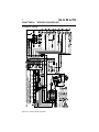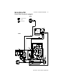
1
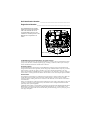
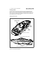
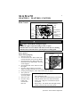
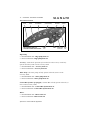
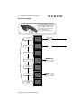
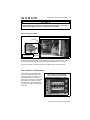
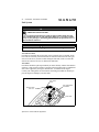
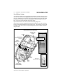
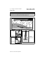
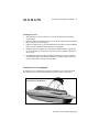
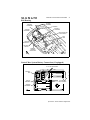
Hull Identification Number: ____________________________________
Engine Serial Number: ________________________________________
The Hull Identification Number
(HIN) is located on the starboard
side of the transom. Be sure to
record the HIN in the space provided above and always refer to the
HIN for all correspondence or
orders.
HIN LOCATION
© 2002 Maxum Technical Publications. All rights reserved.
No part of this publication may be reproduced, stored in any retrieval system, or transmitted in any form
by any means, electronic, mechanical, photocopying, recording or otherwise, without prior written permission of Maxum. Printed in the United States of America.
Proprietary Rights
This document discloses subject matter in which Maxum has proprietary rights. The information and
design disclosed herein were originated by and are the property of Maxum. Neither receipt nor possession
thereof confers or transfers any right to reproduce, copy, alter or disclose the document or any part
thereof, any information contained therein, or to construct boats or any item from it, except by written permission from or written agreement with Maxum. This document is to be returned upon request to Maxum.
General Notes
The material in this document is for information only and is subject to change without notice. While reasonable efforts have been made in the preparation of this document to assure its accuracy, Maxum
assumes no liability resulting from errors or omissions in this document, or from the use of information
contained herein.
Due to our commitment to product improvement, Maxum reserves the right to make changes in the product design, specifications, and equipment at any time without notice or obligation. Illustrations and/or
photos may show optional equipment.
All Maxum products meet or exceed USCG (Unites States Coast Guard) and/or NMMA (National Marine
Manufacturer’s Association) construction standards. Manufactured with 1,1,1 Trichloroethane, a substance which harms public health and environment during the manufacturing process by destroying ozone
in the upper atmosphere.
CONTENTS
CHAPTER 1: ABOUT THIS MANUAL
1
1
1
2
2
3
3
4
Dealer Service
About Your Limited Warranty
Boating Experience
Engine & Accessories Guidelines
Qualified Maintenance
Special Care For Moored Boats
Safety Standards
Carbon Monoxide (CO)
5
6
Warning Labels
6
8
Sources of CO
Warning Label Locations
Hazard Warning Symbols
CHAPTER 2: FEATURES / SYSTEMS
9
Helm Console
9
9
10
12
14
Dash Programming
Electrical System (12 Volt DC)
15
15
Battery Shutoff Switch Key
Fuses and/or Circuit Breakers
16
16
Keyless Ignition
User Code Re-programming Sequence
Touch Panel Controls
Control Max Docking System Electrical Components (if equipped)
Controls
17
18
Control Max Docking System (if equipped)
Control Max Warning Labels
18
19
19
19
20
21
22
Navigation and Interior Lights
Depth Finder
Anchoring
Ski Tow Ring
Hull Exterior Hardware & Drains
Quick Oil Drain System
Fuel System
22
22
23
24
Bilge Blower
Bilge Pump
25
26
27
27
28
29
Fuel Fills and Vents
Fuel Filters
Autofloat Switch
Fresh Water System
Marine Head With Dockside Pump-out
Portable Toilet
Canvas Top
Tonneau Cover (if equipped)
CHAPTER 3: ELECTRICAL ROUTINGS
30
31
31
Deck Routing
Hull Routing
Control Max System Battery Connections (if equipped)
CHAPTER 4: WIRING DIAGRAMS
32
33
12 Volt DC System
Control Max System (if equipped)
1
CHAPTER 1: ABOUT THIS MANUAL
This Owner’s Manual Supplement provides specific information about your boat
that is not covered in the Sport Boat Owner’s Manual. Study the Sport Boat
Owner’s Manual and this supplement carefully. Keep the Sport Boat Owner’s Manual and this supplement on your boat in a secure, yet readily available place.
Dealer Service
•
•
•
•
Ask your dealer to explain all systems before taking delivery of your boat.
Your dealer is your key to service.
Contact your dealer if you have any problems with your new boat.
If your dealer cannot help, call our customer service hotline: 360-435-8957 or
send us a FAX: 360-403-4235.
• Buy replacement parts from any authorized Maxum dealer.
About Your Limited Warranty
• Maxum offers a Limited Warranty on each new Maxum purchased through an
authorized Maxum dealer.
• A copy of the Limited Warranty was included in your owner’s packet.
• If you did not receive a copy of the Limited Warranty, please contact your dealer
or call 360-435-8957 for a copy.
Boating Experience
If this is your first boat or if you are changing to a type of boat you are not familiar
with, for your own comfort and safety, you must obtain handling and operating
experience before assuming command of the boat.
Take one of the boating safety classes offered by the U.S. Power Squadrons or the
U.S. Coast Guard Auxiliary. For more course information, including dates and
locations of upcoming classes, contact the organizations directly:
• U.S. Power Squadrons: 1-888-FOR-USPS (1-888-367-8777) or on the Internet
at: http://www.usps.org
• U.S. Coast Guard Auxiliary: 1-800-368-5647 or on the Internet at:
http://www.cgaux.org
Outside the United States, your selling dealer, national sailing federation or local
yacht club can advise you of local sea schools or competent instructors.
! WARNING!
CONTROL HAZARD! A qualified operator must be in control of the boat at all
times. DO NOT use your boat while under the influence of alcohol or drugs.
Sport Deck • Owner’s Manual Supplement
2
CHAPTER 1: ABOUT THIS MANUAL
Engine & Accessories Guidelines
Your boat’s engine and accessories were selected to provide optimum performance
and service. Installing different engines or other accessories may cause unwanted
handling traits. Should you choose to install a different engine or to add accessories
that will affect the boat’s running trim, have an experienced marine technician perform a safety inspection and handling test before using your boat again.
Certain modifications to your boat will result in the cancellation of your warranty protection. Check with your dealer before making any modifications to
your boat.
The engine and accessories installed on your boat come with their own operation
and maintenance manuals. Read and understand these manuals before operating the
engines and accessories.
NOTICE
When storing your boat please refer to your engine’s operation and maintenance manuals.
Qualified Maintenance
! WARNING!
To maintain the integrity and safety of your boat, only qualified people should
perform maintenance on, or in any way modify: The steering system, propulsion system, engine control system, fuel system, environmental control system,
or electrical system.
Failure to maintain your boat’s systems as designed could violate the laws in your
jurisdiction and could expose you and other people to the danger of bodily injury or
accidental death. Follow the instructions provided in the Sport Boat Owner’s Manual, this Owner’s Manual Supplement, the engine owner’s manual and all accessory
instruction sheets/manuals included in your boat’s owner’s packet.
Sport Deck • Owner’s Manual Supplement
CHAPTER 1: ABOUT THIS MANUAL
3
Special Care For Moored Boats
If moored in saltwater or fresh water, your boat will collect marine growth on its
hull bottom. This will detract from the boat’s beauty, greatly affect its performance
and may damage the gelcoat.
Periodically haul the boat out of the water and scrub the hull bottom with a bristle
brush and a solution of soap and water.
NOTICE
To help seal the hull bottom and reduce the possibility of gelcoat blistering on
moored boats, apply an epoxy barrier coating, such as INTERLUX, Interprotect
2000E/2001E. Cover the barrier coating with several coats of anti-fouling paint.
Many states regulate the chemical content of bottom paints. Ask your local
dealer about the laws in effect in your area.
Safety Standards
Your boat’s mechanical and electrical systems were designed to meet safety standards in effect at the time it was constructed. Some of these standards were mandated by law. All of them were designed to insure your safety, and the safety of
other people, vessels and property.
In addition to this supplement, read the Sport Boat Owner’s Manual, warning
labels, and all literature in your owner’s packet for important safety standards and
hazard information.
!
DANGER!
DANGER
PERSONAL SAFETY HAZARD! DO NOT allow anyone to ride on
parts of the boat not designated for such use.
Sitting on seat backs, lounging on the forward deck, bow riding, gunwale riding
or occupying the transom platform or the aft sunlounge cushions while underway is especially hazardous and WILL cause personal injury or death.
!
DANGER!
DANGER
PERSONAL SAFETY HAZARD! Always secure the anchor and other loose
objects before getting underway. The anchor and other items that are not
properly secured can come loose when the boat is moving and cause personal
injury or death.
Sport Deck • Owner’s Manual Supplement
4
CHAPTER 1: ABOUT THIS MANUAL
Carbon Monoxide (CO)
!
DANGER!
CARBON MONOXIDE POISONING HAZARD!
Carbon monoxide gas (CO) is colorless, odorless, and extremely
dangerous. All engines, generators, and fuel burning appliances
produce CO as exhaust. Direct and prolonged exposure to CO will
cause BRAIN DAMAGE or DEATH.
Signs of CO poisoning include:
• Headache
• Nausea
• Dizziness
• Drowsiness
CO poisoning causes a significant number of boating deaths each year. Called the
"silent killer", CO is an extremely toxic, colorless, odorless and tasteless gas.
Breathing CO blocks the ability of your blood to carry oxygen. The effects are
cumulative, even low levels of exposure can result in injury or death.
Factors increasing the effects of CO include:
• Age.
• Smokers or people exposed to high concentrations of cigarette smoke.
• Consumption of alcohol.
• Lung disorders, heart problems, and pregnancy.
Sport Deck • Owner’s Manual Supplement
CHAPTER 1: ABOUT THIS MANUAL
5
Sources of CO
Sources of CO include:
a. Using the engine or generator
when the boat is moored in a
confined space.
b. Mooring close to another boat that
is running its engine, generator, or
any other CO source.
c. Running the boat with the trim
angle of the bow too high.
d. Running the boat without through
ventilation (station wagon effect).
To correct stationary situations (a) and/or (b):
• Close all windows, portlights and hatches.
• If possible, move your boat away from the source of the CO.
To correct running situations (c) and/or (d):
• Trim the bow down.
• Open windows and canvas.
• When possible, run the boat so that the prevailing winds will help dissipate
the exhaust.
IMMEDIATELY take corrective action when CO is detected or suspected.
Sport Deck • Owner’s Manual Supplement
6
CHAPTER 1: ABOUT THIS MANUAL
Warning Labels
Your boat is affixed with various safety labels at the time of manufacture. These
labels are to alert you and your passengers to potentially hazardous situations.
Make sure that all operators and passengers read and understand all of these labels.
If you suspect that a warning label is damaged or missing, contact an authorized
Maxum Marine dealer for a replacement.
Warning Label Locations
NOTE: LOCATIONS OF WARNING LABELS MAY BE DIFFERENT THAN INDICATED.
FLAMMABLE LIQUIDS
STORAGE WARNING
BOARDING
LADDER
WARNING
POTABLE
WATER
WARNING
FUEL WARNINGS
BOARDING LADDER WARNING
2100 SD
MAX
UM
DOCKING SYSTEM WARNINGS (IF EQUIPPED)
Sport Deck • Owner’s Manual Supplement
CHAPTER 1: ABOUT THIS MANUAL
7
Warning Label Locations, continued
QUALIFIED
OPERATOR
WARNING
DOCKING SYSTEM
SYSTEM WARNING
(IF EQUIPPED)
EMERGENCY
SHUTDOWN
WARNING
BLOWER
WARNING
MAXIMUM
CAPACITY
WARNING
Sport Deck • Owner’s Manual Supplement
8
CHAPTER 1: ABOUT THIS MANUAL
Hazard Warning Symbols
The hazard warning symbols shown below are used throughout this supplement to
call attention to potentially dangerous situations that could lead to either personal
injury or product damage. Read these warnings and follow all safety instructions.
HOT
HAZARD!
FIRE
HAZARD!
PERSONAL INJURY
& FALLING HAZARD!
ROTATING
PROPELLER HAZARD!
EXPLOSION
HAZARD!
OPEN FLAME
HAZARD!
ELECTRICAL
HAZARD!
CO POISONING
HAZARD!
!
DANGER!
This message box alerts you to immediate hazards which WILL cause severe
personal injury or death if the warning is ignored.
!
WARNING!
This message box alerts you to hazards or unsafe practices which COULD
result in severe personal injury or death if the warning is ignored.
!
CAUTION!
This message box alerts you to hazards or unsafe practices which COULD
result in minor personal injury or cause product or property damage if the
warning is ignored.
NOTICE
This message box calls attention to installation, operation or maintenance
information, which is important to proper operation but is not hazard related.
Sport Deck • Owner’s Manual Supplement
9
CHAPTER 2: FEATURES / SYSTEMS
Helm Console
SPEEDOMETER
LED MULTI
FUNCTION DISPLAY
TEMP
TRIM
OIL
TACHOMETER
FUEL
RIGHT TOUCH
PANEL
VOLT
CONTROL MAX™
JOYSTICK
(IF EQUIPPED)
LEFT
TOUCH
PANEL
!
WARNING!
FIRE & EXPLOSION HAZARD! Fuel vapors can explode resulting in
injury or death. Before starting the engine:
• Check the engine compartment bilge for fuel or vapors.
• Run the blower for four minutes and make sure the blower is running.
• Run the blower when the boat is operating below cruising speed.
Keyless Ignition
USER CODE
START
BUTTONS
Engine Starting/Stopping
1. Enter the user code.
2. Press and release the “Start” button. The
LOCK
Unlock LED turns on (Accessory Mode).
LED
3. Press and release the “Start” button. The
Run LED turns on (Run Mode). This step
STOP
can be skipped.
4. Press and hold the “Start” button to crank
RUN
the engine.
LED
5. Press the “Stop” button to turn off the
engine. The Run LED turns off (Accessory Mode).
6. Pressing and holding the “Start” button can restart the engine.
7. The system can
User Code Re-programming Sequence
be locked when in
Accessory Mode.
1. Enter 4 digit user code.
5. Enter user code.
2. Press the 1 and 4 button simultaneously. The unlock
LED will blink if the correct code was entered.
6. Press the “Stop”
button. The
3. Enter a new 4 digit user code followed by the
Unlock LED
start button.
turns off.
4. Repeat step 3. The unlock LED will light steadily
and the system will be in accessory mode.
Sport Deck • Owner’s Manual Supplement
10
CHAPTER 2: FEATURES / SYSTEMS
Touch Panel Controls
BILGE
PUMP
WATER
PUMP
ACCESSORY
* SEE PREVIOUS PAGE FOR
KEYLESS IGNITION INSTRUCTIONS
CONTROL MAX™
(IF EQUIPPED)
LOCK
LED
BLOWER
*START
*STOP *USER CODE RUN
BUTTONS
LED
Bilge Pump
• Press the button once - Bilge pump turns on.
• Press a second time - Bilge pump turns off.
Accessory - Controls the operation of a switched 12-volt accessory. It will only
operate when the system is in the accessory mode.
• Press the button once - Accessory turns on.
• Press a second time - Accessory turns off.
Water Pump - The water pump will only operate when the system is in the
accessory mode.
• Press the button once - Water pump turns on.
• Press a second time - Water pump turns off.
Control Max System™ (if equipped) - Control Max will only operate when the system is in the accessory mode.
• Press the button once - Control Max System turns on.
• Press a second time - Control Max System turns off.
Blower
• Press the button once - Blower turns on.
• Press a second time - Blower turns off.
Sport Deck • Owner’s Manual Supplement
CHAPTER 2: FEATURES / SYSTEMS
LCD SET
LCD MODE
11
COURTESY NAVIGATION &
LIGHTS
ANCHOR LIGHTS HORN
STEREO
CONTROLS
Horn:
• Press and hold the button - Horn sounds. Release to stop.
Navigation & Anchor Lights
• Press the button once - Navigation and anchor lights turn on.
• Press a second time - Navigation lights turn off. Anchor lights remain on.
• Press a third time - Navigation lights turn on. Anchor lights turn off.
• Press a fourth time - Navigation lights off. Anchor lights off.
Courtesy Lights
• Press the button once - Courtesy lights turn on.
• Press a second time - Courtesy lights turn off.
LCD Mode - See Dash Programming.
LCD Set - See Dash Programming.
Stereo Controls - Refer to the stereo instructions for these switch descriptions.
These functions are compatible with the JVC KD-S550 CD Receiver. This Unit has
been modified to accept signals from an external keypad.
The touch panel backlight will turn on for 10 seconds when any button is pressed.
The backlight will also turn on when the navigation lights are on.
Sport Deck • Owner’s Manual Supplement
12
CHAPTER 2: FEATURES / SYSTEMS
Dash Programming
S
Use the M “LCD Mode” switch to
toggle through the 7 basic settings.
Press both M “LCD Mode” and
S “LCD Set” at the same time to
enter or change values.
Arrow(s) show current function.
M
Clock
M and S
Depth, Ft/M
M and S
Distance Log
Trip Log
M and S
To Reset to 0.0
Total Hours
Trip Hours
Seawater Temp
(option)
Sport Deck • Owner’s Manual Supplement
M and S
To Reset to 0.0
CHAPTER 2: FEATURES / SYSTEMS
S to set Hours
M to go to Minutes
S to set Minutes
S decreases
Depth Alarm
Value-M to next
13
M to go to 24:12
S to Select
M to exit
S increases
Depth Alarm
Value-M to next
S to Select
Feet or Meters
M to next
S to
Select Depth
ON or OFF
Note
Setting Depth to METERS
will change Distance and
Trip logs to km (kilometers)
and Seawater Temp (option)
to C (centigrade)
Note
If you see ProG on the
display you have entered the
programming mode. Turn the
key off to exit. Do not
change programmed values.
Sport Deck • Owner’s Manual Supplement
14
CHAPTER 2: FEATURES / SYSTEMS
Electrical System (12 Volt DC)
Thoroughly read and understand this section, the electrical sections of the Sport
Boat Owner’s Manual and all accessory manuals included in your boat’s owner’s
packet. Wiring diagrams are provided in Chapter 4 of this supplement.
!
DANGER!
EXTREME FIRE, ELECTRIC SHOCK
and EXPLOSION HAZARD!
To minimize the risks of fire, electric shock and explosion:
• NEVER install knife switches or other arcing devices in the fuel
compartments.
• NEVER substitute automotive parts for marine parts. Electrical, ignition
and fuel system parts were designed and manufactured to comply with
rules and regulations that minimize risks of fire and explosion.
• Ensure all of the battery switches are in the OFF position before performing any work in the engine spaces.
• DO NOT modify the electrical systems or relevant drawings.
• Only qualified personnel should install batteries and/or perform maintenance on the electrical system.
!
WARNING!
FIRE & EXPLOSION HAZARD!
• Fuel fumes are heavier than air and will collect in the bilge areas where
they can be accidently ignited. Visually and by smell (sniff test), check the
engine and fuel compartments for fumes or accumulation of fuel. Always
use the bilge blowers for at least four minutes prior to engine starting,
electrical system maintenance or activation of electrical devices.
• Minimize the danger of fire and explosion by not exposing batteries to
open flame or sparks. It is also important that no one smoke anywhere
near the batteries.
!
CAUTION!
SHOCK & ELECTRICAL SYSTEM DAMAGE HAZARD!
• NEVER disconnect the battery cables while the engine is running since
damage may occur to your boat’s electrical system components.
• The battery charging systems (alternators and battery charger) are
designed to charge conventional lead-acid batteries. Before installing gelcell (or other new technology) batteries, read and follow the battery
charger’s operating instructions.
Sport Deck • Owner’s Manual Supplement
CHAPTER 2: FEATURES / SYSTEMS
15
NOTICE
Electrical connections are prone to corrosion. To reduce corrosion caused electrical problems, keep all electrical connections clean and apply a spray-on protectant that is designed to protect connections from corrosion.
Battery Shutoff Switch Key
STARBOARD SIDE OF ENGINE COMPARTMENT
BATTERY
BATTERY SHUTOFF
SWITCH KEY
Your boat is equipped with a red battery shutoff switch key. This switch key disconnects the engine and accessories from the battery when the boat is not in use.
Insert the switch key and turn clockwise to enable the DC electrical system.
Fuses and/or Circuit Breakers
The push-to-reset circuit breakers
are located behind the dash in the
starboard storage area. Please read
the electrical section of the Sport
Boat Owner’s Manual for important
safeguards concerning your boat’s
circuit breakers. Some equipment
may have secondary fuse protection
at the unit
PUSH-TO-RESET CIRCUIT BREAKERS
AND ELECTRONIC CONTROL MODULE
Sport Deck • Owner’s Manual Supplement
16
CHAPTER 2: FEATURES / SYSTEMS
Control Max Docking System Electrical Components (if equipped)
VIEW OF ENGINE COMPARTMENT
CONTROL MAX CIRCUIT
BREAKERS (TYPICAL)
PUSH
TO TEST
PUSH TO
RESET
BATTERY
CHARGE
EQUALIZER
50 AMP
CIRCUIT
BREAKERS
ELECTRONIC
CONTROL
UNIT
150 AMP
CIRCUIT
BREAKERS
If your boat is equipped with the Control Max Docking System, it has two additional circuit breakers, a battery charge equalizer, and an electronic control unit.
Controls
Read and
understand
the Controls
section of
both the Sport
Boat Owner’s
Manual and
engine manual, provided
in the
owner’s
packet.
THROTTLE CABLE
SHIFT CABLE
STEERING
CABLE
SHIFT/THROTTLE
LEVER
Sport Deck • Owner’s Manual Supplement
CHAPTER 2: FEATURES / SYSTEMS
17
Control Max Docking System (if equipped)
If your boat is equipped with the Control Max Docking System, read and understand the Mercury Docking System Operation, Maintenance & Warranty Manual.
Carefully follow all cautions and warnings.
Control Max Docking System Thruster Control
JOYSTICK
JOYSTICK
JOYSTICK
JOYSTICK
JOYSTICK
JOYSTICK
Sport Deck • Owner’s Manual Supplement
18
CHAPTER 2: FEATURES / SYSTEMS
Control Max Warning Labels
Navigation and Interior Lights
Read the navigation light section of the Sport Boat Owner’s Manual. The navigation and interior lights supplied with your boat are of top quality, but you should
be aware that failure may periodically occur for a variety of reasons:
•
•
•
•
There may be a blown fuse - replace the fuse in the switch panel.
The bulb may be burned out - carry spare bulbs for replacement.
A wire may be damaged or may have come loose - repair as required.
The bulb base may be corroded - clean the base and coat it with non-conductive
electrical lubricant.
!
CAUTION!
• Conserve battery power. Prolonged operation of cabin interior lights
(overnight) will result in a drained battery.
• Avoid the storage of gear where it would block navigation lights
from view.
Sport Deck • Owner’s Manual Supplement
CHAPTER 2: FEATURES / SYSTEMS
19
Depth Finder
Your boat may come equipped with a depth finder. It will provide you with measurements of water depth beneath the boat and in many cases it may help you locate
schools of fish. The depth finder comes with its own manual. Read this manual
carefully before using the unit.
!
WARNING!
DO NOT use the depth finder as a navigational aid to prevent collision, grounding, boat damage or personal injury. When the boat is moving, submerged
objects will not be seen until they are already under the boat. Bottom depths
may change too quickly to allow time for the boat operator to react. If you suspect shallow water or submerged objects, run the boat at very slow speeds.
Anchoring
Read and understand the Anchoring section of the Sport Boat Owner’s Manual.
!
WARNING!
FLOODING AND SWAMPING HAZARD - Never anchor by the stern alone-there is less freeboard and flooding or swamping is more likely to occur. When
using only one anchor, secure the anchor line to the bow cleat or bow eye.
Ski Tow Ring
Your boat may be equipped with a ski
tow ring. Attach the tow rope as shown
in the photo (right.)
SKI TOW RING
SKI TOW ROPE
Sport Deck • Owner’s Manual Supplement
20
CHAPTER 2: FEATURES / SYSTEMS
Hull Exterior Hardware & Drains
MAX
UM
BOW
EYE
CONTROL MAX
THRUSTER TUNNEL
(IF EQUIPPED)
SINK
DRAIN
UM
MAX
BOW
EYE
BILGE PUMP
DRAIN
CONTROL MAX
THRUSTER TUNNEL
(IF EQUIPPED)
STERN
EYES
TRANSOM
LADDER
TYPICAL TRANSOM
CONTROL MAX
THRUSTER TUNNEL
(IF EQUIPPED)
GARBOARD
DRAIN
Sport Deck • Owner’s Manual Supplement
CONTROL MAX
THRUSTER TUNNEL
(IF EQUIPPED)
TRANSOM PLATFORM
SUPPORTS
CHAPTER 2: FEATURES / SYSTEMS
21
Quick Oil Drain System
All stern drive models are equipped with a quick oil drain system.
To drain the engine oil:
1. Remove the boat from the water.
2. Unscrew the garboard drain plug.
3.
Pull the draw cord until the oil drain plug and the oil drain hose slide out of the
garboard drain.
4.
Place the end of the oil drain hose into a suitable container.
5.
Unscrew the oil drain plug and drain the engine oil.
6.
Replace the oil drain plug.
7.
Push the drain hose back into the bilge.
8.
Replace the garboard drain plug.
Always dispose of waste oil in accordance with local regulations.
QUICK OIL DRAIN SYSTEM
TRANSOM
OIL DRAIN HOSE
OIL DRAIN PLUG
GARBOARD
DRAIN PLUG
ENGINE OIL PAN
DRAW
CORD
BILGE
GARBOARD
DRAIN
Sport Deck • Owner’s Manual Supplement
22
CHAPTER 2: FEATURES / SYSTEMS
Fuel System
!
WARNING!
FIRE/EXPLOSION HAZARD
It is very important that the fuel system be inspected thoroughly the first
time it is filled and then at each subsequent filling. For your safety and the
safety of your passengers, the fueling instructions in the Sport Boat Owner’s
Manual must be followed.
!
CAUTION!
Avoid the storage or handling of gear near the fuel lines, fittings and tank.
Fuel Fills and Vents
Fuel fills are located on the aft port deck. Fuel receptacle caps are marked “GAS”.
Fuel vents are normally located in the hull or transom below and in the same general area as the fill. If you have trouble filling the fuel tank, check to see that the
fuel fill and vent lines are free of obstructions and kinks.
Fuel Filters
Fuel filters should be replaced periodically to ensure that they remain clean and free
of debris. A fine mesh screen filter is located on the fuel pickup tube. An additional
filter, when supplied by the engine manufacturer, is installed on the engine.
Consult your selling dealer or local marina concerning fuel additives that help to
prevent fungus or buildup in your fuel tanks.
FUEL SYSTEM
FUEL TANK
VENT
DECK FITTING
FUEL FILL
FUEL FEED HOSE
TO ENGINE
FUEL TANK
Sport Deck • Owner’s Manual Supplement
CHAPTER 2: FEATURES / SYSTEMS
23
Bilge Blower
!
WARNING!
FIRE/EXPLOSION HAZARD
Operation of the blower system is NOT A GUARANTEE that explosive fumes
have been removed. If you smell any fuel, DO NOT start the engine.
If the engine is already running, immediately shut off the engine and all electrical accessories. Investigate immediately. DO NOT obstruct or modify the ventilation system.
The bilge blower removes fumes from the engine compartment and draws fresh air
into the compartment through the deck vents.
To ensure fresh air circulation, use the bilge blower for at least four minutes before
starting the engine, during starting, and while running the boat below cruising speed.
BLOWER SYSTEM
TO AFT DECK VENTS
BLOWER
AIR FLOW
AFT
Sport Deck • Owner’s Manual Supplement
24
CHAPTER 2: FEATURES / SYSTEMS
Bilge Pump
BILGE PUMP SYSTEM
Your boat has one impeller-type
bilge pump. The bilge pump is
automatically controlled by a
float switch (see "Autofloat
Switch" on page 25). The bilge
pump can also be controlled by
a switch on the dash.
FLOAT
SWITCH
Check the bilge pump often to
make sure it is working properly. To check the bilge pump:
BILGE
PUMP
• Turn on the dash-mounted
switch and make sure that
water in the bilge is pumped
overboard.
LOCATED
UNDER THE
ENGINE
If bilge water is present and the
pump motor is running, but not
pumping:
THRU
HULL
• Inspect the bilge pump hose
for a kink or collapsed area.
If the bilge pump hose is not the
problem, check the bilge pump
housing for clogging debris:
AFT
To remove the power cartridge (FIG. 1):
1. Lift the tab while rotating the fins counterclockwise.
2.
Lift out the power cartridge.
3.
Clear the outer housing of debris.
To reinstall the power cartridge (FIG. 2):
1. Make sure the “O” ring is properly seated.
2.
Coat the “O” ring with a light film of
vegetable or mineral oil.
3.
Align the two cams on either side of the
power cartridge with the two slots on the
outer housing and press the power cartridge into the housing while twisting
clockwise.
4.
To ensure proper reinstallation of the
power cartridge, attempt to twist the fins
counterclockwise without lifting the tab:
The cartridge should stay in place.
Sport Deck • Owner’s Manual Supplement
TAB
FIG. 1
LIGHT FILM
OF OIL
CAM
(TYPICAL)
“O” RING
POWER
CARTRIDGE
SLOT
(TYPICAL)
OUTER
HOUSING
FIG. 2
FIN
CHAPTER 2: FEATURES / SYSTEMS
25
Autofloat Switch
An electromagnetic float (autofloat) switch automatically turns on the bilge pump
whenever bilge water rises above a preset level. An autofloat switch is mounted
next to the bilge pump. The autofloat switch is wired directly to the battery and will
normally function even when the boat is completely shut down and left unattended.
Test the autofloat switch often as follows:
Float Switch Test:
FLOAT SWITCH TEST BUTTON
DOWN - AUTO POSITION
UP - TEST POSITION
1.
Lift the float switch test button to turn on the bilge pump.
2.
If the pump does not turn on, check the inline fuse. If the fuse is good but the
switch doesn’t work, it may indicate a bad switch or possibly a low battery.
3.
Push the test button all the way back down to auto mode.
!
CAUTION!
When test is completed on a float switch, you must push the test button all the
way down to the auto position to turn the switch back to auto mode!
NOTICE
Discharge of oil, oil waste or fuel into navigable waters is prohibited by law. Violators are subject to legal action by the local authorities.
Sport Deck • Owner’s Manual Supplement
26
CHAPTER 2: FEATURES / SYSTEMS
Fresh Water System
Your boat has a fresh water system. This system features a cockpit sink spray faucet
and an aft deck shower and an optional forward deck shower. To turn on this pressure-type (demand) system, push the water pump button located on the dash. Push
the button a second time to turn the water pump off. Turn the pump off when the
boat is not in use and/or when the water tank is empty.
Inspect and clean the water filter, located on the water pump, often.
Stored water can become stagnant and distasteful. Pump the water tank dry before
leaving your boat unattended for long periods of time. Occasionally you may want
to disinfect your water system. Ask your selling dealer about available treatments
and procedures.
FRESH WATER SYSTEM COMPONENTS
TO PULL-OUT
SPRAYER HEAD
AT SINK
AFT
TO PULL-OUT
SPRAYER HEAD ON
AFT DECK
ACCESS WATER
PUMP AND FILTER
THROUGH FLOOR
OF SKI LOCKER
WATER
TANK FILL
DECK FITTING
WATER
TANK
VENT
WATER
TANK
PULL-OUT
SPRAYER HEAD
WATER
PUMP
WATER
FILTER
TO PULL-OUT
SPRAYER HEAD
AT BOW (OPTION)
Sport Deck • Owner’s Manual Supplement
CHAPTER 2: FEATURES / SYSTEMS
27
Marine Head With Dockside Pump-out
If your boat features a marine head and pump-out system, carefully read the manufacturer’s owner’s manual supplied in your owner’s packet.
WASTE TANK
VENT FITTING
PUMP-OUT
FITTING
PUMP-OUT
HOSE
WASTE TANK
VENT HOSE
GUNNEL
FLANGE
MARINE
HEAD
Portable Toilet
Your boat may feature a portable toilet. Read and follow the manufacturer’s operating instructions supplied in your owner’s packet before using your portable toilet.
Sport Deck • Owner’s Manual Supplement
28
CHAPTER 2: FEATURES / SYSTEMS
Canvas Top
CAUTION!
!
Canvas tops are not designed for highway speeds. Before towing, take down and
securely stow the convertible top, side curtains and back cover.
D
C
C
D
A
A
B
B
D
WINDSHIELD
HINGE
SECURING PIN
END EYE
SECURING PIN
DECK HINGE
JAW SLIDE
Sport Deck • Owner’s Manual Supplement
CHAPTER 2: FEATURES / SYSTEMS
29
Installing the Canvas
1. Slide the end eyes of the main bow (A) into the deck hinges and insert the
securing pins.
2. Raise the main bow and slide the end eyes of the aft supports (B) into the deck
hinges and insert the securing pins.
3.
Pull the secondary bow (C) forward and slide the forward brace (D) windshield
hinges over the windshield frame and insert securing pins.
4.
Install the port stern support (D). To determine which end of the support goes
up, lay the support on a flat surface. The end eye that is parallel to the flat surface goes up.
5.
No adjustments to the jaw slides should be needed as they are preset during
manufacturing. Before attempting to adjust the jawslide positions, obtain the
correct measurements from your selling dealer.
Tonneau Cover (if equipped)
A tonneau cover is available for your boat. To attach the cover, start at the front.
The Tonneau cover can be attached with the canvas top in the arch position.
CANVAS TOP FOLDED IN ARCH POSITION
WITH TONNEAU COVER INSTALLED
Sport Deck • Owner’s Manual Supplement
30
CHAPTER 3: ELECTRICAL ROUTINGS
Deck Routing
NOTE: VIEW IS OF THE UNDERSIDE OF THE DECK
PORT
DOCK LIGHT
(OPTION)
STARBOARD
DOCK LIGHT
(OPTION)
PORT
BOW
LIGHT
STARBOARD
BOW LIGHT
SPEAKER
DOME
LIGHT
COURTESY
LIGHT
HORN
STEREO
CIRCUIT
BREAKERS
DASH
12 VOLT
RECEPTACLE
DOME
LIGHT
COURTESY
LIGHT
SPEAKER
SPEAKER
WATER
PUMP
12 VOLT
RECEPTACLE
SHIFTER
FIRE
SYSTEM
(OPTION)
COURTESY
LIGHT
STERN
LIGHT
STEREO
MEMORY
SPEEDO
FUEL FILL
GROUND
TRIM
PUMP
GROUND
BAR
ENGINE
PLUG
DECK
PLUG
Sport Deck • Owner’s Manual Supplement
CHAPTER 3: ELECTRICAL ROUTINGS
31
Hull Routing
GROUND
ON ENGINE
TO DECK
HARNESS
BLOWER
BATTERY
CHARGER
STARTER
ON ENGINE
BILGE PUMP AND
FLOAT SWITCH
FUEL
TANK
GROUND
ON BATTERY
BATTERY
SWITCH
POSITIVE
TERMINAL
ON BATTERY
AFT
Control Max System Battery Connections (if equipped)
3 X 12 VOLT BATTERIES
CONTROL
BOX
CIRCUIT
BREAKER
TO CONTROL
MAX HARNESS
GROUND
ON ENGINE
AFT
Sport Deck • Owner’s Manual Supplement
32
CHAPTER 4: WIRING DIAGRAMS
12 Volt DC System
Sport Deck • Owner’s Manual Supplement
CHAPTER 4: WIRING DIAGRAMS
33
Control Max System (if equipped)
BOW
= CONNECTION
= FUSE
-
+
= BATTERY
DASH
SWITCH
DASH PLUG
PORT
STBD
6
BATTERY
CHARGER
FUEL
BP
150A
FUEL FILL
BLOWER
TRIM PUMP
GROUND
ANCHOR
LIGHT
Sport Deck • Owner’s Manual Supplement
Owner’s Notes
Owner’s Notes
Owner’s Notes