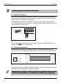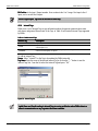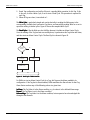
1
DABin
User´s Manual
www.exemys.com
DABin User’s Manual
Exemys
Exemys Products are in constant evolution to satisfy our customer needs. For that reason, the specifications
and capabilities are subject to change without prior notice.
Updated information can be found at www.exemys.com
Copyright © Exemys, 2006. All Rights Reserved.
Rev. 4
DABin User’s Manual
Exemys
Table of Contents
INTRODUCTION
1.1
1.1.1
1.1.2
1.1.3
1.2
1.2.1
1.2.2
1.2.3
9
About this Manual ___________________________________________________
___________________________________________________ 9
Purpose of the Manual
DABin accompanying CD-ROM
Information on the Web
9
9
10
DABin General Description ____________________________________________
____________________________________________ 10
Why use DABin?
General Description
DABin Models
INSTALLATION
10
11
11
12
2.1
General Description _________________________________________________
_________________________________________________ 12
2.2
Power Connection
Connection __________________________________________________
__________________________________________________ 13
2.3
Ethernet Connection _________________________________________________
_________________________________________________ 13
2.4
Serial Connection ___________________________________________________
___________________________________________________ 14
2.4.1
2.4.2
2.5
2.5.1
2.5.2
2.6
RS-232 Serial Connection
RS-485 and RS-422 Serial Connection
Inputs and Outputs __________________________________________________
__________________________________________________ 15
DABin’s Digital Inputs
DABin’s Digital Outputs
3.1.1
3.1.2
3.2
3.2.1
3.2.2
3.2.3
3.2.4
3.3
3.3.1
3.3.2
3.3.3
3.4
3.4.1
16
18
Mounting _________________________________________________________
_________________________________________________________ 19
GENERAL CONFIGURATION
3.1
14
14
20
DABin Configuration Manager (DCM) ____________________________________
____________________________________ 20
DCM Installation
DABin Configuration Manager General Description
20
21
Network Configuration Parameters ______________________________________
______________________________________ 22
Searching for Exemys Devices in Network
DABin Basic Network Parameters
Device Locator
ARP Table Method for IP Address Configuration
22
23
25
26
Security in DABin ___________________________________________________
___________________________________________________ 27
DABin’s Security Scheme
Changing Standard user Configuration
Changing Administrator Password (admin)
27
28
29
Date and Time in DABin ______________________________________________
______________________________________________ 29
How to set up Date and Time in DABin
29
DABin User’s Manual
Exemys
DABIN MODBUS CONFIGURATION
31
4.1
How DABin Modbus Work________________________________
Work _____________________________________________
_____________________________________________ 31
4.2
Creating a Modbus Configuration File ____________________________________
____________________________________ 34
4.3
Serial Port Configuration ______________________________________________
______________________________________________ 34
4.4
E-Mail Configuration________________________________
Configuration _________________________________________________
_________________________________________________ 35
4.5
Tags Configuration __________________________________________________
__________________________________________________ 37
4.5.1
4.5.2
4.5.3
4.5.4
4.5.5
4.5.6
4.5.7
4.6
4.6.1
4.6.2
Tags Administration
Modbus Tags Configuration
Digital Inputs and Outputs Tags
Internal Tags
Value Writing Restrictions
Tag Alarm Configuration
Tag Value Scaling
38
38
40
41
42
42
43
Sending and Receiving Configuration________________________________
Configuration_____________________________________
_____________________________________ 44
Connecting to DABin using DCM
Sending and Receiving Configuration
DABIN HOSTLINK CONFIGURATION
44
45
46
5.1
How DABin Hostlink Work________________________________
Work_____________________________________________
_____________________________________________ 46
5.2
Creating a Hostlink Configuration File ____________________________________
____________________________________ 49
5.3
Serial Port Configuration ______________________________________________
______________________________________________ 49
5.4
E-Mail Configuration________________________________
Configuration _________________________________________________
_________________________________________________ 50
5.5
Tags Configuration __________________________________________________
__________________________________________________ 52
5.5.1
5.5.2
5.5.3
5.5.4
5.5.5
5.5.6
5.5.7
5.6
5.6.1
5.6.2
Tags Administration
Hostlink Tags Configuration
Digital Inputs and Outputs Tags
Internal Tags
Value Writing Restrictions
Tag Alarm Configuration
Tag Value Scaling
53
53
54
55
56
57
57
Sending and Receiving Configuration________________________________
Configuration_____________________________________
_____________________________________ 58
Connecting to DABin using DCM
Sending and Receiving Configuration
DABIN DF1 CONFIGURATION
58
59
60
6.1
How DABin DF1 Works _______________________________________________
_______________________________________________ 60
6.2
Creating a DF1 Configuration File _______________________________________
_______________________________________ 63
6.3
Serial Port Configuration ______________________________________________
______________________________________________ 63
6.4
E-Mail Configuration________________________________
Configuration _________________________________________________
_________________________________________________ 64
DABin User’s Manual
Exemys
6.5
Tags Configuration __________________________________________________
__________________________________________________ 66
6.5.1
6.5.2
6.5.3
6.5.4
6.5.5
6.5.6
6.5.7
6.5.8
6.6
Tags Administration
DF1 Tags Configuration
Notes on PLC reads and writes for inputs and outputs
Digital Inputs and Outputs Tags
Internal Tags
Value Writing Restrictions
Tag Alarm Configuration
Tag Value Scaling
Sending and Receiving Configuration________________________________
Configuration_____________________________________
_____________________________________ 74
6.6.1
6.6.2
Connecting to DABin using DCM
Sending and Receiving Configuration
WEB SITE DESIGN
7.1
How a Web Site Works in DABin
Inserting an Applet in a Web Page
The Communication Applet (CApplet)
The Data Applets (DApplets)
DApplets Parameters
The Number Applet: num.class
The Bar Applet: bar.class
The Image Applet: img.class
The Vectorial Applet: vec.class
The Text Applet: txt.class
77
78
79
81
82
82
82
83
83
Static Pages (SSI)
(SSI) ___________________________________________________
___________________________________________________ 84
7.4.1
7.4.2
7.4.3
7.4.4
7.4.5
7.5
76
DApplets: The Basic Library ____________________________________________
____________________________________________ 82
7.3.1
7.3.2
7.3.3
7.3.4
7.3.5
7.4
76
Applets Web page Design _____________________________________________
_____________________________________________ 77
7.2.1
7.2.2
7.2.3
7.2.4
7.3
74
74
Introduction _______________________________________________________
_______________________________________________________ 76
7.1.1
7.2
67
67
69
69
70
71
72
73
Inserting a SSI in HTML Code
The Tag Value in SSI
The Alarm Value in SSI
The Text by Value in SSI
Execute Links in SSI pages
84
84
85
85
86
Creating the Web site file _____________________________________________
_____________________________________________ 87
7.5.1
7.5.2
7.5.3
Administration of files in a Web Site Archive
Transferring the Web Site
Using a Standard FTP Client
TOOLS
88
88
89
91
8.1
The DCM Tag Monitor________________________________
Monitor ________________________________________________
________________________________________________ 91
8.2
Serial Commands Console _____________________________________________
_____________________________________________ 92
8.2.1
8.2.2
8.2.3
Resetting configuration to factory defaults
Changing the Administrator password
Seeing the firmware version and ending the commands console
93
93
93
DABin User’s Manual
Exemys
A. COMMAND SET DOWNWARD COMPATIBILITY IN NEWER ALLENBRADLEY PLCS
95
B. DATA LOGGING
96
B.1.
Introduction _______________________________________________________
_______________________________________________________ 96
B.2.
Configuration ______________________________________________________
______________________________________________________ 96
B.3.
Reading the logged data ______________________________________________
______________________________________________ 98
B.4.
SSI with log status __________________________________________________
__________________________________________________ 99
B.5.
Example __________________________________________________________
__________________________________________________________ 99
RS485 Port Connection____________ _________________________________________101
Tables
Table 1 - Chapters of the Manual _______________________________________________________________ 9
Table 2 - DABin CD-ROM Contents _____________________________________________________________ 10
Table 3 - DABin Models _____________________________________________________________________ 11
Table 4 - Yellow Indicator Led Status Code _______________________________________________________ 14
Table 5 - Digital Inputs Technical Specifications ___________________________________________________ 17
Table 6 - Digital Outputs Technical Specifications __________________________________________________ 18
Table 7 - Users and their access to DABin ________________________________________________________ 28
Table 8 - Types of Modbus Tags and its representation ______________________________________________ 40
Table 9 - Address Ranges in Modbus DABin ______________________________________________________ 40
Table 10 - DABin Internal Tags ________________________________________________________________ 41
Table 11 - Types of Hostlink Tags and its representation _____________________________________________ 54
Table 12 - DABin Internal Tags ________________________________________________________________ 55
Table 13 - Types of DF1 Tags and its representation _______________________________________________ 69
Table 14 - File Types of DF1 Tags ______________________________________________________________ 69
Table 15 - DABin Internal Tags ________________________________________________________________ 70
Table 16 - DABin's Web Site characteristics ______________________________________________________ 77
Table 17 - Communication Applet Parameters ____________________________________________________ 78
Table 18 - State Messages in the Information Dialog box ____________________________________________ 80
Table 19 - Error Messages in Information Dialog box _______________________________________________ 80
Table 20 - Alarm Messages in the Information Dialog box ___________________________________________ 80
Table 21 - DApplets Common Parameters________________________________________________________ 81
Table 22 - Color Values______________________________________________________________________ 81
Table 23 - Number Applet Parameters __________________________________________________________ 82
Table 24 - Bar Applet Parameters ______________________________________________________________ 82
Table 25 - Image Applet Parameters ____________________________________________________________ 83
Table 26 - Vectorial Applet Parameters __________________________________________________________ 83
Table 27 - Text Applet Parameters _____________________________________________________________ 83
Table 28 - Format specifiers for VALUE SSI Command_______________________________________________ 85
Figures
Figure 1 - DABin functional diagram ____________________________________________________________ 11
Figure 2 - Front and Rear View of DABin_________________________________________________________ 12
DABin User’s Manual
Exemys
Figure 3 - Power connection detail _____________________________________________________________
Figure 4 - Connecting DABin to an Ethernet Network _______________________________________________
Figure 5 - Connection of DABin (DTE) to a PC (DTE) using RS-232 Serial Port _____________________________
Figure 6 - Connector Detail for RS-485 or RS-422 network connection __________________________________
Figure 7 - DABin Connected to RS-485 and RS-422 networks _________________________________________
Figure 8 - Inputs and Outputs connectors in different DABin models ____________________________________
Figure 9 - Digital Input connected to an external Device with independent power supply ____________________
Figure 10 - Different ways to connect a Digital Input _______________________________________________
Figure 11 - Connection of Digital Outputs ________________________________________________________
Figure 12- Wall-mounting adapter _____________________________________________________________
Figure 13 – Wall mounting ___________________________________________________________________
Figure 14 - DCM Main window and its elements___________________________________________________
Figure 15 - Searching Devices Locally ___________________________________________________________
Figure 16 - Remote DABin Search ______________________________________________________________
Figure 17 - DABin Network Properties Dialog box __________________________________________________
Figure 18 - Administrator Password Dialog Box ___________________________________________________
Figure 19 - Device Locator Main window ________________________________________________________
Figure 20 - Device Locator Properties Dialog box __________________________________________________
Figure 21 - Users & Passwords in the Properties dialog box __________________________________________
Figure 22 - Date and Time in the Properties dialog box ______________________________________________
Figure 23 - Scan Cycle of DABin Modbus ________________________________________________________
Figure 24 - Write Cycle in DABin Modbus ________________________________________________________
Figure 25 - Read Cycle in DABin Modbus ________________________________________________________
Figure 26 - Alarm Control Cycle in DABin Modbus _________________________________________________
Figure 27 - New File dialog box _______________________________________________________________
Figure 28 - Serial Port Configuration Page of DABin Modbus _________________________________________
Figure 29 - E-Mail configuration page of DABin Modbus_____________________________________________
Figure 30 - E-Mail Address Edit Dialog box _______________________________________________________
Figure 31 - Tags Page configuration for DABin Modbus _____________________________________________
Figure 32 - Modbus Tag Configuration __________________________________________________________
Figure 33 - Digital Inputs / Output Tag Configuration _______________________________________________
Figure 34 - Internal Tag List __________________________________________________________________
Figure 35 - Value Configuration Page ___________________________________________________________
Figure 36 - Alarm Configuration Page___________________________________________________________
Figure 37 - Scale configuration page____________________________________________________________
Figure 38 - Receiving Configuration from DABin ___________________________________________________
Figure 39 - Sending Configuration to Connected DABin _____________________________________________
Figure 40 - Scan Cycle of DABin Hostlink ________________________________________________________
Figure 41 - Write Cycle of DABin Hostlink ________________________________________________________
Figure 42 - Read Cycle of DABin Hostlink ________________________________________________________
Figure 43 - Alarm Control Cycle of DABin Hostlink _________________________________________________
Figure 44 - New File dialog box _______________________________________________________________
Figure 45 - Serial Port Configuration Page for DABin Hostlink_________________________________________
Figure 46 - E-Mail configuration page of DABin Hostlink_____________________________________________
Figure 47 - E-Mail Address Edit Dialog box _______________________________________________________
Figure 48 - Tags Page configuration for DABin Hostlink _____________________________________________
Figure 49 - Hostlink Tag Configuration __________________________________________________________
Figure 50 - Digital Inputs / Output Tag Configuration _______________________________________________
Figure 51 - Internal Tag List __________________________________________________________________
Figure 52 - Value Configuration Page ___________________________________________________________
Figure 53 - Alarm Configuration Page___________________________________________________________
Figure 54 - Scale configuration page____________________________________________________________
Figure 55 - Receiving Configuration from DABin Hostlink ____________________________________________
Figure 56 - Sending Configuration to Connected Hostlink DABin_______________________________________
Figure 57 - Scan Cycle of DABin DF1____________________________________________________________
13
13
14
15
15
16
17
17
18
19
19
21
22
23
23
24
25
26
28
30
31
31
32
33
34
35
36
37
38
39
40
41
42
43
44
45
45
46
46
47
48
49
50
51
52
52
53
55
56
56
57
58
59
59
60
DABin User’s Manual
Exemys
Figure 58 - Write Cycle of DABin DF1 ___________________________________________________________
Figure 59 - Read Cycle of DABin DF1 ___________________________________________________________
Figure 60 - Alarm Control Cycle of DABin DF1 ____________________________________________________
Figure 61 - New File dialog box _______________________________________________________________
Figure 62 - Serial Port Configuration Page for DABin DF1 ____________________________________________
Figure 63 - E-Mail configuration page of DABin DF1 ________________________________________________
Figure 64 - E-Mail Address Edit Dialog box _______________________________________________________
Figure 65 - Tags Page configuration for DABin DF1_________________________________________________
Figure 66 - DF1 Tag Configuration _____________________________________________________________
Figure 67 - Digital Inputs / Output Tag Configuration _______________________________________________
Figure 68 - Internal Tag List __________________________________________________________________
Figure 69 - Value Configuration Page ___________________________________________________________
Figure 70 - Alarm Configuration Page___________________________________________________________
Figure 71 - Scale configuration page____________________________________________________________
Figure 72 - Receiving Configuration from DABin DF1 _______________________________________________
Figure 73 - Sending Configuration to Connected DF1 DABin __________________________________________
Figure 74 - DABin Web Page with Applets _______________________________________________________
Figure 75 - The CApplet in a Web Browser _______________________________________________________
Figure 76 - The Number Applet________________________________________________________________
Figure 77 - Contextual Menu of DApplets ________________________________________________________
Figure 78 - Change Value dialog box ___________________________________________________________
Figure 79 - Change value for Digital Tags ________________________________________________________
Figure 80 - Information Dialog box for a Dapplet __________________________________________________
Figure 81 - The Number Applet________________________________________________________________
Figure 82 - The Bar Applet ___________________________________________________________________
Figure 83 - The Image Applet _________________________________________________________________
Figure 84 - The Vectorial Applet _______________________________________________________________
Figure 85 - The Text Applet___________________________________________________________________
Figure 86 - New File dialog box _______________________________________________________________
Figure 87 - Web Site Window in DCM___________________________________________________________
Figure 88 - FTP Transfer in DCM _______________________________________________________________
Figure 89 - DCM Tag Monitor _________________________________________________________________
Figure 90 - Tag Write dialog box for Tag Monitor __________________________________________________
60
61
62
63
64
65
66
67
68
70
71
72
72
73
74
75
76
78
79
79
79
79
80
82
82
82
83
83
87
88
89
91
92
Listings
Listing 1 - A Simple page with a CApplet inserted........................................................................................................78
Listing 2 - The Bar Applet with some Parameters .........................................................................................................81
Listing 3 - An SSI command ..........................................................................................................................................84
Listing 4 - Standard Link Example.................................................................................................................................86
Listing 5 - CGI call using the HTTP GET Method ...........................................................................................................86
Listing 6 - Getting the Web Site file using the FTP.EXE.................................................................................................89
Listing 7 - Sending a Web Site file to DABin's FTP Server usign FTP.EXE ......................................................................90
Listing 8 - Welcome message to the DABin Serial Commands Console ........................................................................93
Listing 9 - Using the factreset command to reset configuration to Factory deafults .....................................................93
Listing 10 - Usign the password command ...................................................................................................................93
Listing 11 - Using the ver command to see the current firmware version .....................................................................93
Listing 12 - Using the end command to finish the Commands Console ........................................................................94
DABin User’s Manual
Introduction
Chapter 1
Chapter
Introduction
In this chapter you will be introduced to the general aspects about this manual and DABin. Use
this chapter as a guide for the reading of this manual.
If you are a new User of DABin we recommend you to read the General Description of DABin to
have an accurate vision about functions and general characteristics of DABin.
1.1 About this Manual
1.1.1 Purpose of the Manual
The purpose of this manual is to provide the correct instructions of Installation, configuration and
operation of DABin.
In General, DABin has been developed with easy-of-use philosophy in mind. For this reason, any
person with basic knowledge in any of these areas can configure and operate DABin successfully:
TCP/IP Communication
Simple Web Page design
Some experience in Industrial Protocols such as Modbus or Hostlink.
In the chapters specifically written for any of the above areas, the standard user will count with
the help of Notes, Warnings and Links of interest on the World Wide Web.
In Table 1 you can see a detailed description of the chapters included in this manual and who may
be oriented to in each case.
Table 1 - Chapters of the Manual
Chapter
Oriented to
1 - Introduction
2 - Installation
3 - General Configuration
4 - DABin Modbus Configuration
5 - DABin Hostlink Configuration
6 - DABin DF1 Configuration
All
Installers and Maintenance
Network Administrators and System Administrators
SCADA Operators or the like (Modbus only Model)
SCADA Operators or the like (Hostlink only Model)
SCADA Operators or the like (DF1 only Model)
7 - Web Site Design
Programmers and Web Page Designers
SCADA Operators or the like
8 - Tools
Programmers and Web Page Designers
SCADA Operators or the like
1.1.2 DABin accompanying CDCD-ROM
DABin accompanying CD-ROM contains the Software needed for proper configuration, samples
and the complete documentation of the product.
www.exemys.com
Rev. 4
Page 9
DABin User’s Manual
Introduction
In Table 2 is shown a detail of the contents of this CD-ROM.
Table 2 - DABin CDCD-ROM Contents
Contents
Description
dcmsetup.exe
Program Application for DABin Configuration (DCM )
Web Page Samples for DABin
Configuration Samples for DABin
Applets to use in DABin Web Pages
Sun Java Runtime
Java Runtime Environment 2 to make Applets run in your Web Browser
DABin_UM_E.pdf
Manual of DABin
DABIN_DS_E.pdf
DABin Datasheet
1.1.3 Information on
on the Web
To get information about the last changes, firmware and software upgrades, and to keep
documentation up to date, enter our Web Site:
www.exemys.com
ON THE WEB
You will also find information about new Exemys products, press releases, accessories and new
development tools.
There are published Application Notes and Technical Notes about DABin and other Exemys
products.
1.2 DABin General Description
1.2.1 Why use DABin?
The fast growth up of TCP/IP networks in industry areas facilitated the remote monitoring and
supervision, reducing costs and increasing productivity and efficiency.
DABin achieves this in an economic manner, with easy development, almost without
maintenance, flexibly and security, using the software tools you already know: a standard Web
Browser, a standard E-Mail client, an FTP client, etc.
Economic:
Economic The enormous infrastructure of a SCADA system is not needed with DABin, reducing
development costs, maintenance and support.
Rapid Deployment:
Deployment DABin may be configured and working in just hours, not months or even years
as most SCADA applications.
Universal Access:
Access All DABin functionality (including DABin configuration) is available to an
authorized user with an Internet connection in any place of the World.
Flexibility:
Flexibility The innumerable ways to configure DABin makes it easy-to-adapt to any application.
DABin Digital inputs and outputs, makes possible to connect DABin to non-industrial protocolenabled devices.
No Risk:
Risk Like any SCADA system DABin provides all monitoring and supervision functionality
remotely, without the risk of personnel or equipment.
www.exemys.com
Rev. 4
Page 10
DABin User’s Manual
Introduction
1.2.2 General Description
To achieve all these goals, DABin incorporates a complete and efficient functionality:
Acquires data from an embedded Serial Port, using an industrial protocol like Modbus or Hostlink,
and from its digital inputs.
Web Site Configuration
File
System
Web
Browser
(Client)
FTP Server
Web
Server
Inputs and
Outputs
Actuator
Digital Sensor
TAGS
Serial
Communication
RS-232/485/422
Alarm Controller
PLC
PLC
SMTP
E-mail Alarms
Figure 1 - DABin functional diagram
An Embedded Web Server lets the operator see DABin’s internal Web Site to visualize the
acquired values and change them, from any standard Web Browser.
DABin can send one or more e-mails notifying the Alarm State of any of the acquired values.
The operator can actuate on DABin’s outputs remotely from the Web.
The embedded Web Site can be changed easily using a standard FTP client or the application
software distributed with DABin.
1.2.3 DABin Models
Exemys launched to market different DABin Models.
Depending the needs, a different model with more or less Digital Inputs and Outputs can be
chosen, or with configurable RS-232/485/422 Serial Port.
Table 3 - DABin Models
www.exemys.com
Model
Serial Protocol
Inputs
Outputs Serial Ports
DABin - 1083 - ST - MB
DABin - 1C43 - ST - MB
DABin - 1083 - ST - HL
DABin - 1C43 - ST - HL
DABin - 1083 - ST - DF1
DABin - 1C43 - ST - DF1
Modbus ASCII / RTU
Modbus ASCII / RTU
Hostlink
Hostlink
DF1
DF1
8
4
8
4
8
4
3
3
3
3
3
3
Rev. 4
1 RS-232 Serial Port
1 Configurable RS-232/485/422 Serial Port
1 RS-232 Serial Port
1 Configurable RS-232/485/422 Serial Port
1 RS-232 Serial Port
1 Configurable RS-232/485/422 Serial Port
Page 11
DABin User’s Manual
Installation
Chapter 2
Chapter
Installation
DABin can be easily installed following the instructions in this Chapter. Connection to Power,
Ethernet, Serial Ports and Digital Inputs and Outputs are described in detail.
2.1 General Description
DABin’s case has the following elements:
1. Ethernet 10BaseT RJ-45 Connector with indicator Leds.
2. Serial Port RS-232 DTE DB9-Male Connector.
3. Terminal Block including:
Power (VIN).
Connection for Common o reference for Digital Inputs-Outputs (GND).
Voltage Output for connection of dry contacts to Digital Inputs (V+).
Digital Inputs.
Digital Outputs.
Serial Port in mode RS-485 (available in some models)
Serial Port in mode RS-422 (available in some models)
4. Wall mounting accessory.
5. DIN Rail Mounting accessory (optional).
(1) Ethernet Connector
Net Indicator Led
(yellow)
Status Indicator Led
(2) RS-232 Connector
(3) Terminal Block
(green)
(4) Wall Mounting Accessory
(5) DIN Rail Mounting Accessory
Figure 2 - Front and Rear View of DABin
www.exemys.com
Rev. 4
Page 12
DABin User’s Manual
Installation
For optional accessories for installation ask our sales team.
NOTE
2.2 Power Connection
This product must be installed and powered according to its ratings and installation instructions.
The unit shall be powered from a NEC class 2 source of supply or a LPS source, having an output
rated 9-26 Volts AC, 9-30 Volts DC, 200 mA min..
The installation of this product inside shall be in accordance with the NEC, specifically Article
725-54. Wiring from/to this unit is to be Class 2 wiring and shall be segregated from other wiring
in the equipment as noted in the NEC.
1
2
Vin
Vin
3
4
GND V out
9-30 VDC
9-26 VAC
Figure 3 - Power connection detail
The Vout voltage output is provided in order to connect dry contacts to DABin’s Digital Inputs. It
can drive up to 60mA and it is fuse protected.
2.3 Ethernet Connection
Figure 4 shows the connector RJ-45 Ethernet 10BaseT (1) for Ethernet network connection.
It can be connected to a LAN through a Hub or Switch, or to a PC directly using a crossover cable.
RX + (1)
RX + (1)
RX - (2)
RX - (2)
TX + (3)
TX + (3)
TX - (6)
TX - (6)
DABin
HUB
Figure 4 - Connecting DABin to an Ethernet Network
The yellow indicator led, included in the Ethernet connector, shows the network connection status
and if DABin’s network parameters are properly configured.
TIP
www.exemys.com
Although DABin has no assigned IP Address, the Device Locator application software can be used
in a PC in the same Network in order to test that Ethernet
Ethernet connection has been properly set up.
Rev. 4
Page 13
DABin User’s Manual
Installation
See also: “Device Locator” on page 25
Table 4 - Yellow Indicator Led Status Code
Yellow Led Code
Description
It is ½ second on and ½ off
Turned on constantly
It blinks very fast
It is turned off during almost a second and it turns on for
short periods of time (like a beacon)
It is turned on during almost a second and it turns off for
short periods of time
Has been turned on and it is initializing.
Is searching for a DHCP Server
There is no carrier in the Ethernet connection
It has an IP Address and it is working properly
DABin detects carrier in Ethernet connection but has no
assigned IP Address.
2.4 Serial Connection
DABin provides an RS-232 Serial Port in all models. In some models, the Serial Port can be
configured as either RS-485 or RS-422.
The RS-232 DTE DB9-Male connector (2) can be used to connect any device using the same
DABin’s Protocol (Modbus), or also to enter the Serial Commands Console.
NOTE
In models where DABin’s Serial Port can be configured as RSRS-485/422, it is no necessary to
configure the Serial Port as RSRS-232 before entering the Serial Commands Console. You can enter
the Serial Command Console connecting the Serial Port
Port RSRS-232 to any PC RSRS-232 Serial Port
although DABin’s Serial Port is in other mode.
2.4.1 RSRS-232 Serial Connection
The RS-232 Serial Connection, included in all DABin models, is found in connector DB9-Male (2).
To connect another DTE to DABin’s RS-232 Serial Port, use a crossover cable, as shows figure 5.
PC
DABin
DB9 Female
DB9 Female
RxD
(2)
(3)
TxD
TxD
(3)
(2)
RxD
(5)
(5)
GND
GND
Figure 5 - Connection of DABin (DTE) to a PC (DTE) using RSRS-232 Serial Port
2.4.2 RSRS-485 and RSRS-422 Serial Connection
In models where the Serial Port can be configured as RS-485 or RS-422, DABin can be connected
to RS-485 or RS-422 network for proper data acquisition.
When the Serial Port is configured as either RS-485 or RS-422, a connection must be done
through Terminal Block (3). RS-485 network connection uses the last 2 connectors and RS-422
network connection uses the last 4 connectors.
www.exemys.com
Rev. 4
Page 14
DABin User’s Manual
Installation
TR+
TRR+
R-
RS-232
15
14
13
12
RS-485
RS-422
Figure 6 - Connector Detail for RSRS-485 or RSRS-422 network connection
RS-485
TR+ (15)
Data +
TR- (14)
Data -
DABin
Data +
Data -
Data +
Data -
RS-422
TR+ (15)
R+
TR- (14)
R-
R+ (13)
T+
R- (12)
T-
DABin
R+
R-
T+
T-
R+
R-
T+
T-
Figure 7 - DABin Connected to RSRS-485 and RSRS-422 networks
2.5 Inputs and Outputs
The number of Digital Inputs and Outputs provided with DABin depend on models.
All Inputs and Outputs can be found at the Terminal Block (3), starting at connector number 5.
DABin also provides the special connectors Vout and GND: Voltage output for dry contact
connection and reference or common for external Field Devices connection respectively.
www.exemys.com
Rev. 4
Page 15
DABin User’s Manual
Installation
1
2
3
4
5
6
7
8
9
10
11
12
Vin
Vin
GND
Vout
O0
O1
O2
I0
I1
I2
I3
R-
5
6
7
8
9
10
11
12
I0
I1
I2
I3
I4
I5
I6
I7
13
14
15
TR-
TR+
13
14
15
O0
O1
O2
R+
DABin-1C43-ST
1
2
3
4
Vin
Vin
GND
Vout
DABin-1083-ST
Figure 8 - Inputs and Outputs connectors in different DABin models
ON THE WEB
For more information about Digital Inputs and Digital Outputs in all Exemys Products, including
DABin, refer to Technical Note TNTN-11 “Inputs and Outputs”.
http://www.exemys.com
2.5.1 DABin’s Digital Inputs
DABin’s Digital Inputs are based on transistors in Current Sinking Mode, activated when a voltage
in the range 3.5 to 28VDC referenced to GND is applied.
This voltage may be provided from either, an external field device working in Current Sourcing
Mode or with dry contacts.
To activate Digital Inputs from an external field Device with independent power supply: connect
reference GND to Common of that Device, as seen on figure 9.
To activate Digital Inputs with a dry contact with an independent power supply, connect as
shown in figure 10A.
To activate Digital Inputs with a dry contact with the same power supply, proceed as shown in
figure 10B.
To activate Digital Inputs with a dry contact without any additional power supply, use connector
Vout as shown in figure 10C.
www.exemys.com
Rev. 4
Page 16
DABin User’s Manual
Installation
DABin
Dispositivo de Campo
(PLC, Sensor, Codificador, etc)
+vcc
+Vdc
SALIDA de Tensión
(3.5 a 28 VDC Max.)
Sinking
GND (COMÚN)
(Sourcing)
COMÚN
Fuente de
alimentación
del equipo
+
9-30 VDC
Fuente de
Alimentación
Figure 9 - Digital Input connected to an external Device with independent po
power
wer supply
DABin
+VCC
+ 3.5 - 28 VDC
Sinking
Fuente de
Alimentación
GND (COMÚN)
A
+
B
9-28 VDC
Fuente de
Alimentación
+
9-28 VDC
Fuente de
Alimentación
C
+
9-28 VDC
Fuente de
Alimentación
Figure 10 - Different ways to connect a Digital Input
Table 5 - Digital Inputs Technical Specifications
Digital Inputs
Sinking. Allows sensors and Current Sourcing Devices
Inputs Type
Operating Voltage Range
Input Current
www.exemys.com
3.5 to 28 VDC
1 to 11 mA
Rev. 4
Page 17
DABin User’s Manual
Installation
2.5.2 DABin’s Digital Outputs
DABin’s Digital Outputs are Open Collector. Thus when active, they are electrically tied to GND.
Any load connected to an output should be powered in the range 3 to 45 VDC.
To connect an Output to a load whose power supply is different to that used to power DABin:
Connect the reference GND to the independent power supply reference as shows figure 11A.
To connect an Output to a load with the same power supply that power DABin: Connect the
reference GND to the power supply reference as shown in figure 11B.
CARGA
(Relay, Lámpara, etc)
OUTPUT
(Open Collector)
CARGA
(Relay, Lámpara, etc)
GND (COMÚN)
+
3-45 VDC
Fuente de
Alimentación
A
+
9-30 VDC
Fuente de
Alimentación
B
+
9-30 VDC
Fuente de
Alimentación
Figure 11 - Connection of Digital Outputs
Table 6 - Digital
Digital Outputs Technical Specifications
Digital Outputs
Open Collector. Current Sinking
Output Type
Maximum Load Voltage
Current
www.exemys.com
3 to 45 VDC Max.
130mA Max. Per Output
Rev. 4
Page 18
DABin User’s Manual
Installation
2.6 Mounting
Remove the wall-mounting adapter (included) from the device.
Then mount the adapter to the wall using two screws, as shown in figure 12.
76 mm
2,795 inches
Figure 1212- WallWall-mounting adapter
Last, attach the device to the fixed adapter, as shown in Figure 13.
Figure 13 – Wall mounting
www.exemys.com
Rev. 4
Page 19
DABin User’s Manual
General Configuration
Chapter 3
Chapter
General Configuration
Once installed, DABin must receive the general configuration parameters that make it work in
your Ethernet Network. This chapter gives detailed instructions of the most fundamental
configuration parameters for DABin. These fundamental parameters are network configuration
parameters, DABin authorized users and Date and Time.
3.1 DABin Configuration Manager (DCM)
DABin Configuration Manager (DCM) is the application program that comes with the product and
is used to configure DABin, locally o remotely, through a TCP/IP network.
It has been developed with easy-to-use philosophy allowing configuring either, basic or advanced
functions of DABin.
DCM can be installed on Windows 98/Me, Windows 2000/NT4 and Windows XP.
ON THE WEB
Enter frequently to www.exemys.com to download the latest version of DCM and keep
documentation up to date.
DCM doesn’t have to be installed in a PC within the same LAN DABin is, but be sure that the
application program will have access to DABin, locally or remotely throw the TCP/IP network.
DCM uses HTTP Protocol to configure DABin once it has a valid IP Address assigned,
transparently.
If DABin has never been configured, it will look for a DHCP Server in order to obtain an IP Address
at startup. If the network where DABin is installed doesn’t have a DHCP Server, use any of the
following methods to start configuring DABin for the first time:
Install DCM in a PC within the same LAN DABin is connected to, and use DCM or Device Locator
to assign DABin an IP Address.
If no PC in the same LAN DABin is connected to have any of the operating systems supported by
DCM or Device Locator, follow the steps of the ARP Table Method to assign DABin an IP Address.
See also: “Device Locator” on page 25 and “ARP Table Method for IP Address Configuration” on page 26
3.1.1 DCM Installation
Installation
To install DCM follow these steps:
Insert the DABin accompanying CD and execute setup.exe to begin the installation program.
The Welcome screen will appear, follow the instructions of the Installation Wizard that will
prompt for the necessary information to complete installation. Click “Next” to continue.
User information: Enter a user name and the name of the company and click “Next” to continue.
www.exemys.com
Rev. 4
Page 20
DABin User’s Manual
General Configuration
Destination Folder: Select the destination folder where the application program will be installed.
Installation Type: You can choose any of the following installation types: Typical, Minimum or
Custom.
Program Folder: Enter the name of the Program Folder that will contain all executable elements in
your Programs Menu.
Wait for the Installation Wizard to complete copying all the necessary files to your hard disk, and
press “Finish” to end installation process.
Once installed you will see a folder in your Programs Menu containing all links to Exemys
Application programs installed, DABin Configuration Manager (DCM) and Device Locator.
3.1.2 DABin Configuration Manager General Description
Figure 14 shows the main DCM window. The DCM window elements allow easy navigation and
configuration of all DABin available simultaneously, and also allows configuration of any Exemys
Product network parameters.
Tool Bar
Work Area
Connection Status
Devices List
Contextual Help
Figure 14 - DCM Main window and its elements
These are the elements composing the DCM main window:
Tool Bar:
Bar At the top is the tool bar. You will find commands also available in the application
menus.
Work area:
area In the middle there is the Work area, where all configuration windows will appear.
Devices List:
List Below the work area is the Devices List. It contains all Exemys devices found by DCM
(locally or remotely)
Connection Status:
Status At the status bar is the text indicating if DCM is connected to a DABin or not.
www.exemys.com
Rev. 4
Page 21
DABin User’s Manual
General Configuration
Contextual Help:
Help At the left in the status bar, a panel shows contextual help about the menu and
tool bar commands.
TIP
Work
ork area. To change its
The size of the Devices List can be changed, reducing or increasing the W
size, move the mouse cursor over the superior division line of the List and drag to the desired
size.
3.2 Network Configuration Parameters
DABin network parameters must be configured in first. DCM, Device Locator or the ARP Table
method described later in this chapter can be used to configure these parameters.
3.2.1 Searching for Exemys Devices in Network
The search of all available DABin connected to the network can be achieved locally or remotely.
The devices connected to the same LAN can be searched locally. And the devices connected in
other networks can be found using the Search Remote Device command.
You can search and configure any Exemys Product using DCM. Remember that searching a nonnonDABin device can only be done locally.
To search for
for devices in the LAN (any Exemys Product):
Product) Click on the button on the tool bar o
select command “Search Local Devices” from “Devices” menu. For a couple of seconds, DCM will
search devices in the local network and will show them in the Devices List.
Figure
Figure 15 - Searching Devices Locally
To search for devices remotely beyond the LAN (only DABin):
DABin) Select command “Search Remote
Device” from menu “Devices”. Enter IP Address or Remote Host in the dialog box and click “Ok”
to start searching. For a couple of seconds, DCM will search that device and it will show it in the
Devices List if found.
www.exemys.com
Rev. 4
Page 22
DABin User’s Manual
General Configuration
Figure 16 - Remote DABin Search
NOTE
To find a DABin remotely, it must have an assigned IP Address. If you need to find a DABin
remotely, and the PC connection to the network needs a HTTP Proxy server, DCM must be
configured with the same parameters than your standard Web Browser. Ask your Network
administrator for these parameters.
3.2.2 DABin Basic Network Parameters
You can change any network parameters of DABin (or any Exemys Product) entering the
Properties Dialog box.
To enter to the Properties Dialog box, select the device from the Devices List and then select the
“Properties of...” command from “Devices” menu.
Figure 17 - DABin Network Properties Dialog box
www.exemys.com
Rev. 4
Page 23
DABin User’s Manual
General Configuration
The Properties Dialog box can be shown left clicking over the device in the Devices List and then
selecting “Properties of...” from the contextual menu.
TIP
Once the Properties Dialog box is displayed, all network parameters can be entered:
Host Name:
Name Device Name for identification purposes only. Enter a name for the device to
distinguish it in the Devices List. This name is for identification only, not to access DABin’s Web
Server.
Enable DHCP:
DHCP If the box is checked, DABin will search a DHCP at startup. If the LAN where DABin
is connected to has a DHCP Server, check the box to make DABin acquire all network parameters
automatically at startup.
IP:
IP IP Address. Ask your Network administrator to assign DABin a static IP Address.
Netmask:
Netmask Netmask of the local network.
Gateway:
Gateway Default Gateway in the local network.
Preferred DNS Server:
Server Default DNS Server IP Address. DABin uses this Server to resolve the SMTP
Server name. This network parameter can be changed only if DABin is assigned an IP Address
different than 0.0.0.0.
Alternative DNS Server:
Server Alternative DNS Server IP Address. In the case that DABin couldn’t resolve
the SMTP Server name with the Default DNS Server, it will to resolve it with this alternative
Server. Only can be changed when DABin is assigned an IP Address different than 0.0.0.0.
!
Some DHCP Servers not always assign the same IP Address to the same device. If DABin IP
Address changes can be hard to find it from your Web Browser.
CAUTION
Change these Network configuration parameters and press “Ok” to configure DABin.
To enter the DNS Servers IP Addresses DABin must have assigned an IP Address different than
0.0.0.0. To configure DABin for the first time assign it an IP Address (static or by DHCP) and then
enter the properties dialog box again to configure the DNS Servers IP Addresses.
Figure 18 - Administrator Password Dialog Box
NOTE
www.exemys.com
The Administrator Password is not enabled by default. If it is the first time DABin is configured
configured
left the password blank when DCM prompts for it.
Rev. 4
Page 24
DABin User’s Manual
General Configuration
DCM will prompt for the Administrator password to configure network parameters. In general,
DCM will prompt for the Administrator password when trying to do any of the following tasks:
Change DABin Network parameters.
Change standard user name and its password.
Change Administrator password.
Connect to DABin to get or set general configuration or its internal Web Site.
Once the Administrator password is entered, DCM will configure DABin with the new network
parameters.
DABin will reset after changing these values. In a couple of seconds DABin will start working
again with the new network parameters.
3.2.3 Device Locator
The Device Locator Application program is a small software installed with DCM. It is used for
configuration of network parameters of all Exemys Products.
Host name (identification), IP Address, Netmask and Gateway can be changed, but DNS Servers IP
Addresses cannot be changed within Device Locator.
You must know the DABin’s Administrator password to change this parameters using the Device
Locator.
TIP
It doesn’t matter if the device is not properly configured. If it is connected to the LAN, and
working, Device Locator will find it.
Figure 19 - Device Locator Main window
window
At startup, Device Locator searches for all Exemys devices connected to the LAN and shows them
in the Devices List. If you want Device Locator to search devices again click the “Query Network”
button to refresh.
Select the device from the Devices List to change its network parameters, and click the
“Properties...” button to see the Properties dialog box of that device.
www.exemys.com
Rev. 4
Page 25
DABin User’s Manual
General Configuration
Change any of the network parameters as desired in the Properties dialog box and click “Ok” to
configure it.
NOTE
If the Device has an administrator
administrator password configured (enabled) it must be typed in the “Device
Password” edit box before proceeding.
Figure 20 - Device Locator Properties Dialog box
If Device Locator couldn’t find a device, verify the following:
If the device is turned on and it is connected to the network correctly.
If the device is connected to the same LAN than that the PC running Device Locator is.
If Device Locator throws an error when trying to configure a device with new network
parameters, verify the following:
If the device is turned on and it is connected to the network correctly.
If the Administrator password of the device has been typed correctly in the Properties
dialog box.
ON THE WEB
Check for the version of Device Locator selecting the “About” menu.
menu. Device Locator will show
you a dialog box with the actual version. Enter our Web Site and get the latest version available
at www.exemys.com.
www.exemys.com.
3.2.4 ARP Table Method for IP Address Configuration
DABin IP Address is factory default to 0.0.0.0, which means that will search for a DHCP server at
startup.
When turned on, the device tries to negotiate an IP Address with the DHCP Server for a maximum
period of 10 seconds. Elapsed this period of time, if negotiation with DHCP Server failed, DABin
www.exemys.com
Rev. 4
Page 26
DABin User’s Manual
General Configuration
will try again 60 seconds later. This process will repeat indefinitely until a DHCP Server assigns
DABin an IP Address or the user assigns DABin a static IP Address.
If you want to assign DABin a static IP Address, it could be assigned using the ARP Table method.
At startup, during the first 7 seconds, DABin will wait for an IP Address configuration PING
(ICMP). If the device receives a PING, with the destination IP Address different than that
configured in DABin, it will take this destination IP Address, configure it, and reset with this new
network parameter. After these 7 seconds, the device will answer the PING normally
Follow these steps to configure DABin with this method:
1. In Windows, add an entry in the ARP table of a PC in the same LAN DABin is, using the
command:
arp –s 192.168.0.100 00-0B-FA-XX-XX-XX
In Unix, the command to add an entry to ARP table is:
arp –s 192.168.0.100 00:0B:FA:XX:XX:XX
Where 00-0B-FA-XX-XX-XX is the MAC of the device. The last 3 numbers depends on your Exemys
device.
2. Send a PING to the IP Address just added to the ARP table with the command
ping 192.168.0.100 –t
the –t option sends the PING continuously.
3. Connect DABin to the network and turn it on. The PC will not receive answer of the PING, but
at least a few seconds later.
4. When DABin starts answering the PING, it will have configured the new IP Address.
3.3 Security in DABin
3.3.1 DABin’s Security Scheme
To access the internal Web page in DABin, DABin configuration and DABin’s FTP Server, a simple
and effective security scheme is used.
Basically, DABin recognizes 3 users:
admin:
admin Is the Administrator user that has granted access to all configuration and internal
FTP Server. Its name is fixed and it is admin. Only administrator password can be changed.
Standard user (user):
(user) Is the user with granted access to internal DABin’s Web site through a
Web Browser. This user can be an SCADA operator and has access to see and change the
Tag values. The standard user username and its password can both be changed.
anonymous:
anonymous Is the standard user with access to DABin’s FTP server without a password, but
it has read-only access to file system. The username “anonymous
anonymous”
anonymous cannot be changed.
www.exemys.com
Rev. 4
Page 27
DABin User’s Manual
General Configuration
Table 7 - Users and their access to DABin
User
admin
Standard user
anonymous
!
CAUTION
Permission
All DABin Configuration: Read and Write
FTP Server for Web Site: Read and Write
Web Site access through a Web Browser
FTP Server Read-Only Access (no password)
password
ord is changed, don’t
DABin is factory defaulted without an Administrator password. If this passw
forget it or loose it, because you will have to re enter the administrator password using the Serial
Commands Console throw RSRS-232 port.
3.3.2 Changing Standard user Configuration
Standard user username and password can be changed as desired. Any standard Web browser
will prompt for this username and password when trying to access DABin’s Web Site, even if the
standard user password is empty.
If standard user password is empty, but authentication is enabled then enter the standard user
username and left the password empty when the Web browser prompts for it.
To change the standard user configuration (username and password), enter the Properties dialog
box in DCM:
Open the Properties dialog box selecting the Device from the Devices List, and then selecting the
command “Properties of...” from the “Devices” menu.
Figure 21 - Users & Passwords in the Properties dialog box
www.exemys.com
Rev. 4
Page 28
DABin User’s Manual
General Configuration
Select the “Users & Passwords” page in the Properties dialog box. DCM will send DABin a
command to retrieve current configuration and will show it in the dialog box.
In the “Username” edit box, enter the new username for the standard user.
Enter the new standard user password twice in “New password” and “Retype password” edit
boxes for DCM to verify the password is set properly.
DCM will ask you for the current administrator password in order to change these parameters.
TIP
Authentication in Web Server can be disabled if you left blank the field “Username”. Then the
Web browser will not prompt for any username
username and password when entering DABin’s Web site.
3.3.3 Changing Administrator Password (admin)
For administrator user (admin
admin),
admin only its password can be changed. This user has granted access to
all DABin’s configuration and to DABin’s FTP server (read and write)
You can leave DABin without an Administrator password, as is by default, but is recommendable
to change the password for security reasons.
To change the Administrator password use the Properties Dialog box of the device:
Open the Properties dialog box selecting the Device from the Devices List, and then selecting the
command “Properties of...” from the “Devices” menu.
Select the “Users & Passwords” page in the Properties dialog box. DCM will send DABin a
command to retrieve current configuration and will show it in the dialog box.
Enter the new Administrator password twice in “New password for admin” and “Retype
password for admin” edit boxes for DCM to verify the password is set properly.
Click on the “Set Administrator” button to configure the new password.
DCM will ask you for the current administrator password in order to change this parameter.
3.4 Date and Time in DABin
When DABin sends e-mails informing the Alarm status of one of the Tags, it includes in the
message body the date and time the alarm started.
Date and Time are maintained by DABin and is constantly actualized even if it is turned off.
3.4.1 How to set up Date and Time in DABin
If the sending e-mail functionality of DABin is to be used is recommendable that Date and Time
be synchronized.
To synchronize date and time follow these steps:
Open the Properties dialog box selecting the Device from the Devices List, and then selecting the
command “Properties of...” from the “Devices” menu.
Select the “Date & Time” page in the Properties dialog box. DCM will send DABin a command to
retrieve current configuration and will show it in the dialog box.
www.exemys.com
Rev. 4
Page 29
DABin User’s Manual
General Configuration
Figure 22 - Date and Time in the Properties dialog box
Enter current date and time in “Current DABin Date” and “Current DABin Time” respectively. The
“Now” button will synchronize DABin’s time with the PC.
Click the “Set Date and Time” button to change to the values just entered.
www.exemys.com
Rev. 4
Page 30
DABin User’s Manual
DABin Modbus Configuration
Chapter 4
Chapter
DABin Modbus Configuration
DABin Modbus acts as master, making queries to the slaves about the value of each Tag
configured and sending the write queries triggered from DABin’s Web page or Tag Monitor in
DCM. In this chapter we will give the details to configure DABin Modbus to achieve these
functions.
NOTE
Model
del only. DABin Serial Protocol is not
The present Chapter information refers to DABin Modbus Mo
configurable.
4.1 How DABin Modbus Work
DABin Modbus is based in Read cycles, Write cycles and acknowledges of Tag Alarms. Each cycle
starts with a wait of the Scan Time period, configured by user, and then sends the pending write
queries, sets the pending acknowledgments of Tag Alarms and Reads the rest of the Tags.
In figure 23 is shown the complete Scan Cycle:
1. DABin waits for the Scan Time period: This time, configured by user, can be set from 0ms to
10000ms.
Wait SCAN TIME
Send WRITE
WRITE this
Tag ?
No
Response
Correct ?
No
Yes
Yes
WRITE Cycle
READ Cycle
Synchronize
Status
Yes
Next
Tag ?
Unmark Pending WRITE
No
Yes
End
Figure 23 - Scan Cycle of DABin Modbus
www.exemys.com
Figure 24 - Write Cycle in DABin Modbus
Rev. 4
Page 31
DABin User’s Manual
DABin Modbus Configuration
2. Reads Tag configuration and verifies if there is a pending Write operation for this Tag. If this
is the case, it starts a Write Cycle, if not it starts a Read Cycle. This procedure is repeated for
each Tag.
3. When all Tags are done, it starts back to 1.
The Write Cycle is particularly simple and consists basically in sending the Write query to the
corresponding Modbus slave, synchronize Tag Status, and unmark the pending Write so as not to
repeat the writing in further cycles. Figure 24 shows the complete Write Cycle.
The Read Cycle is like the Write one, but it differs because it includes an Alarm Control Cycle.
Once the reading of the Tag has been successfully done, it synchronizes the Tag Value and Status,
and then starts an Alarm Control Cycle. The Read Cycle is shown in Figure 25.
Send READ
Response
Correct ?
No
Yes
Synchronize Value
and Status
Synchronize
Status
ALARM CYCLE
End
Figure 25 - Read Cycle in DABin Modbus
For DABin to start an Alarm Control Cycle for a Tag, this Tag must be Alarm-enabled in its
configuration. If the Tag has its Alarm enabled, DABin maintains the Alarm Status for that Tag.
Alarm Status can have any of the following values at a given time:
In Alarm:
Alarm The Tag Value is in the Alarm condition, e.g. its value is in the defined Alarm range.
Normal: The Tag Value is not in the Alarm condition.
Normal
Acknowledge:
Acknowledge The Tag Value is in the Alarm condition, but an operator has acknowledged this
through a Web Browser.
www.exemys.com
Rev. 4
Page 32
DABin User’s Manual
DABin Modbus Configuration
Alarm
Enabled ?
No
End
End
Yes
Status = Normal
Status = Alarm
Pending
Acknowledge ?
No
In Alarm
Condition ?
No
Status = Acknowledge
In Alarm
Condition ?
No
Yes
Yes
Set Status to
“Alarm”
Set Status to
“Acknowledge”
Set Status to
“Normal”
E-mail
Enabled?
Yes
Yes
No
Queue e-mail
End
Figure 26 - Alarm Control Cycle in DABin Modbus
Basically, Alarm Control Cycle is:
1. If Tag is in Alarm State, DABin verifies if an operator has acknowledged this. If this is the
case, Tag Alarm State is changed to Acknowledged for the next Read Cycle of this Tag.
2. If Tag is in Normal Alarm State, DABin verifies if the value is in the Alarm condition. If so, it
changes its Alarm State to Alarm and an e-mail to the internal e-mails queue is added if Tag if
e-mail enabled.
3. If Tag is in Acknowledged Alarm State, DABin verifies if the Tag value is in Alarm condition. If
so, the Alarm State remains unchanged, if not the Alarm State is changed to Normal.
NOTE
www.exemys.com
The total time DABin spends in reading all configured Tags will depend on the total count of Tags
and Scan Time period. If any of the Tags is not properly configured, and DABin receives no
response from the Slave after the maximum time (Timeout), this time will be added to the total
time the Scan Cycle takes. Set the Timeout and Scan Time parameters with caution following
following the
instructions in this Manual.
Rev. 4
Page 33
DABin User’s Manual
DABin Modbus Configuration
4.2 Creating a Modbus Configuration File
DCM administrates DABin’s configuration files with .dab extension. A configuration file can be
created or downloaded from a DABin for modification or back up.
TIP
Several configuration
configuration .dab files can be saved with different configuration and send any of them at
any given moment. Then DABin will reset and start working with the new configuration in just
seconds.
See also: “Sending and Receiving Configuration” on page 44
To create a new configuration file follow these steps:
Select command “New” from “File” menu. The New File dialog box will appear to select the new
file type to create.
Figure 27 - New File
File dialog box
Select “DABin Modbus Configuration” from the list in the New File dialog box to create a new
Modbus configuration file.
The new configuration file will be shown in the DCM Work area.
TIP
When a file is modified but not yet saved, DCM will mark it with an asterisk (*) besides the name
of the file at the caption.
4.3 Serial Port Configuration
In the case that Modbus Tags are going to be configured in DABin, the Serial Port must be
configured correctly and coherently with configuration of the devices connected to DABin’s Serial
Port.
The Serial Port parameters are:
Com Type:
Type This parameter has effect only in DABin models where the Serial Port is configurable.
RS-232, RS-485 or RS-422 can be selected.
Baud Rate (bps):
(bps) Is the transmission and reception rate of the Serial Port. Any value in the range
2400bps to 115200bps can be selected.
www.exemys.com
Rev. 4
Page 34
DABin User’s Manual
DABin Modbus Configuration
Parity:
Parity Is the Serial Port Parity. Select either, None (No parity), Odd (Odd parity) or Even (Even
parity).
Figure 28 - Serial Port Configuration Page of DABin Modbus
Modbus Format:
Format Is the Serial Modbus Format. Select ASCII or RTU depending on the device
connected to DABin.
Scan Time:
Time Is the delay time in milliseconds DABin will wait before starting a new Scan Cycle.
ASCII Mode Maximum Response Timeout
Timeout (Message Timeout): In ASCII Mode, is the maximum
time in milliseconds DABin will wait for a response from the slave. This parameter is ignored in
RTU Mode.
RTU Mode Maximum Response Timeout (Packet Timeout): In RTU Mode, is the maximum time in
bytes units DABin will wait for a response from the slave. This parameter is ignored in ASCII
Mode.
TIP
The Scan Time and Message Timeout parameters can be entered manually, clicking the “...”
button besides de track bar.
4.4 E-Mail Configuration
DABin can send an e-mail when a Tag is in Alarm condition.
For this functionality to be available, all information to send e-mails must be given to DABin.
Each time a Tag enters the Alarm condition with the Alarm e-mail enabled, DABin will queue a
message to be sent as fast as possible.
DABin messages queue can save up to 128 alarms at the same time. If DABin couldn’t send
messages for a wrong configuration and the queue becomes full, DABin will not add more
messages until a place appears in the queue.
www.exemys.com
Rev. 4
Page 35
DABin User’s Manual
!
DABin Modbus Configuration
DABin empties the Alarm messages queue at startup or reset. Verify that all messages have been
send before changing configuration or before resetting the device manually.
CAUTION
DABin’s internal e-mail sending machine retries sending a message a number of times after a
given period if the e-mail couldn’t be send in a given time. All these parameters are configurable
in DABin.
If DABin couldn’t send an e-mail, it can be configured to:
Erase the message from the queue after it has tried to send it the number of times configured.
Not to Erase the message and keep trying sending the message. This option can make a queue
full if DABin is not correctly configured.
Figure 29 - EE-Mail configuration page of DABin Modbus
E-Mail configuration is composed of the following:
Enable relaying:
relaying Mark the check box to enable e-mail relaying service.
SMTP server:
server Name or IP Address of SMTP server.
Server requires authentication: Check this option if the SMTP server needs User+Password
authentication (plain text authentication). (*)
Username:
Username Name required for user authentication.
Password:
Password Secret key required for user authentication.
Confirm Password:
Password Retype of the secret key.
Delivery timeout:
timeout This is the maximum lapse (in seconds) DABin attempts to send an e-mail.
Retries:
Retries How many times DABin will try to send an e-mail before removing it from the queue. If
this parameter is 0, DABin will keep trying to send it without erasing the message from the
queue.
Retry every (seconds):
(seconds) Delay between retries.
Source ee-mail address:
address Source address used for outgoing e-mails.
Destination ee-mail addresses:
addresses An e-mail can be delivered to up to 5 different destinations. Add a
new destination by clicking on the “Add” button. The “Edit” button can be used to change an e-
www.exemys.com
Rev. 4
Page 36
DABin User’s Manual
DABin Modbus Configuration
mail address, while the “Delete” button removes one destination from the list. Change the
relaying priority by rearranging the list using the arrows on the right side: DABin relays e-mail
from top to down.
(*) This feature applies to firmware version 2.1 and higher.
Figure 30 - EE-Mail Address Edit Dialog box
!
CAUTION
For DABin to resolve the SMTP Server name correctly, at least one DNS IP Address must be
properly configured. DABin will get the IP Address of the SMTP Server before sending ee-mails. If
no DNS Server IP Address is configured in DABin, SMTP Server IP Address must be entered
explicitly. Ask your network administrator to obtain this information.
See also: “Network Configuration Parameters” on page 22
4.5 Tags Configuration
DABin accept up to 128 different Tags. Tags in Modbus can be:
Modbus Tags:
Tags These are the Tags DABin will ask the Modbus slaves connected to the Serial Port
(RS-232/485/422). They must contain the information needed to access the Modbus slave, e.g.
Modbus Slave Address and Register Address.
DABin’s Digital Inputs Tags:
Tags Digital Tags whose value is the mirror of the current state of one of
DABin’s input. Its configuration must contain the number of Digital Input and is exclusively readonly.
DABin’s Digital Outputs Tags:
Tags Digital Tags whose value is the mirror of the current state of one of
DABin’s output. The operator can change this value and this change will be reflected in the
corresponding DABin Digital Output.
Internal Tags:
Tags Special Digital Tags that provide information of status of serial communication and
general alarm of the rest of the Tags. Can be included or not.
www.exemys.com
Rev. 4
Page 37
DABin User’s Manual
DABin Modbus Configuration
Figure 31 - Tags Page configuration for DABin Modbus
In general, any Tag configuration includes:
General Configuration:
Configuration Where DABin will search for Tag value, slave information (if it is a Modbus
Tag) and the Type of the Tag.
Tag writing restrictions:
restrictions If the Tag is read-only or not, or if the written value must be in a given
range.
Alarm Configuration
Configuration:
ation If the Tag is going to be Alarm-enabled and its Alarm condition, and if
DABin must send an e-mail to all destination addresses when the alarm condition is detected.
Scale:
Scale DABin can make a simple calculation with the acquired value. The result of this calculation
is the value of the Tag that will be seen by the operator.
4.5.1 Tags Administration
Tags can be added, edited or deleted from the list that will be sent to a DABin. In the Tags Page
in the configuration file the complete list of Tags with all configuration can be seen.
To add a new Tag:
Tag Select command “Add Tag...” from “Configuration” menu. The New Tag
dialog box will appear.
To edit an existing Tag:
Tag Select the Tag to edit in the List, then select “Edit Tag...” from
“Configuration” menu. The Edit Tag dialog box will appear with current Tag configuration.
To Delete a Tag:
Tag Select the Tag to delete from the Tags List, then select command “Remove Tag”
from “Configuration” menu. DCM will ask for confirmation before deleting the Tag.
4.5.2 Modbus Tags Configuration
Configuration
The Modbus Tags are the Tags whose value will be searched by DABin using the Serial Port.
www.exemys.com
Rev. 4
Page 38
DABin User’s Manual
DABin Modbus Configuration
Figure 32 - Modbus Tag Configuration
To configure a Modbus Tag, enter the parameters described below:
Source:
Source Select “Modbus Serial” to make a Modbus Tag. DABin will acquire the value from a slave
connected to its Serial Port.
Tag Name:
Name Enter the Name of the Tag. DABin will identify this Tag with its Name.
Modbus Unit ID:
ID Is the Address or number of Modbus slave DABin will ask for the value of the
Tag. Can be in the range 1 to 255.
Tag Type:
Type Select the type of the Tag. In table 8 are shown all the types supported by DABin.
NOTE
If a Tag is any of the Integer types but an scaling function of the value is configured, DABin will
convert the type of Tag to Float.
Register Table:
Table Is the register table the required register for the Tag belongs to. Holding Register,
Input Register, Input Status or Coil Status can be selected.
NOTE
Registers in tables Input Status and Coil Status are Digital and “Single
“Single Bit” type must be selected
for them. Also registers in tables Input Status and Input Registers must be declared as readread-only.
Register Address:
Address Is the Address of the Modbus Register. Note that changing the Register Table
changes the first digit in Register Address edit box. In table 9 are listed all the address ranges
supported by DABin Modbus.
Bit Position:
Position Is the Bit number (position) for the “Word Bit” type. A value between 0 and 15 can
be entered, when 0 is the least significant bit.
32 bit Register (Enron):
(Enron) If Tag is representing a long integer (Long) or a floating point value
(Float), then the way the slave uses this value can be changed. If the slave addresses just a 32-bit
register for these types (Long and Float) then mark the check box. If the slave addresses 2 16-bit
registers for Long and Float types, leave the check box unmarked.
www.exemys.com
Rev. 4
Page 39
DABin User’s Manual
DABin Modbus Configuration
Table 8 - Types of Modbus Tags and its representation
Type
Description
Range
Unsigned int
Signed int
Long
Long Inverted
Float
Float Inverted
BCD
Word Bit
Single Bit
16-bit Unsigned Integer
16-bit Signed Integer
32-bit Signed Integer
32-bit Signed Integer. Modicon Format.
32-bit Float
32-bit Float. Modicon Format.
16-bit BCD format
Bit in 16-bit Word
Bit for Digital Input / Output, Coil or Input Status
0..65535
-32768..32767
-2147483648..2147483647
-2147483648..2147483647
0000..9999
0, 1
0, 1
Table 9 - Address Ranges in Modbus DABin
Type
Range
Coil Status
Input Status
Input Register
Holding Register
000001..065536
100001..165536
300001..365536
400001..465536
4.5.3 Digital Inputs and Outputs Tags
Tags related with DABin’s Digital Inputs/Outputs can be defined. Digital Inputs and Digital
Outputs are both enumerated from 0.
See also: “Inputs and Outputs” on page 15
!
CAUTION
The number of Digital Inputs and Outputs depends on the DABin Model. DABin will ignore Tags
with Digital Inputs/Outputs that do not exist in the model in use.
Figure 33 - Digital Inputs / Output Tag Configuration
To configure a Tag related with DABin’s Digital Inputs / Outputs:
Source:
Source Select “Digital Input” or “Digital Outputs” to relate the Tag with DABin’s Digital
Inputs/Outputs.
Tag Name:
Name Enter the Name of the Tag. DABin will identify this Tag with its Name.
www.exemys.com
Rev. 4
Page 40
DABin User’s Manual
DABin Modbus Configuration
Bit Position:
Position Is the Input / Output number. Enter a value in the 0 to 7 range. First Input is the 0
input, and so as with the Outputs.
DABin’s Digital Inputs Tags must be declared as readread-only.
NOTE
4.5.4 Internal Tags
DABin uses a set of internal Tags to give information about the general communication status
with slaves and general Alarm status of the Tags. In Table 10 are listed all internal Tags supported
by DABin.
Table 10 - DABin Internal Tags
Internal Tag
Description
_COMMERROR
Digital Tag. The value becomes 1 when a Serial Communication error is detected.
Digital Tag. The value becomes 1 when any Tag (Except Internal Tags) is in Alarm State,
acknowledged or not
_ALARM
_ALARMNAK
Digital Tag. The value becomes 1 when any Tag (Except Internal Tags) is in Alarm State and has
not been acknowledged by an operator.
To add an Internal Tag:
Source:
Source Select “Internal” for the Tag to be updated by DABin internally.
Tag Name:
Name Enter the name of the desired Internal Tag or click on the “...” button to see the
Internal Tags lists. From the list select the Internal Tag and press “Ok”.
Figure 34 - Internal Tag List
TIP
www.exemys.com
Enable Alarm and EE-mail sending in Internal Tags to receive notification
notification when DABin detects a
failure in communication or any Tag enters the Alarm condition.
Rev. 4
Page 41
DABin User’s Manual
DABin Modbus Configuration
All Internal Tags must be declared as readread-only.
NOTE
4.5.5 Value Writing Restrictions
Tags in DABin can be configured as write-enabled in a given range of values or read-only. This
can be done from the Value Configuration Page in the Configuration Tag dialog box.
Figure 35 - Value Configuration Page
Read only:
only if the check box is marked DABin will not allow the operator to change the value of
the Tag with a writing command from a Web browser.
The Tags representing Digital Outputs cannot be declared as Read Only.
NOTE
Writing Limits:
Limits marking the check box and entering the Minimum and Maximum values allowed
for writing, DABin will allow an operator to write a value into this range.
4.5.6 Tag Alarm Configuration
To make DABin control the Alarm status of a Tag, the Tag must have its Alarm enabled.
See also: “How DABin Modbus Works” on page 31
www.exemys.com
Rev. 4
Page 42
DABin User’s Manual
DABin Modbus Configuration
Figure 36 - Alarm Configuration Page
Alarms in DABin can be triggered by a range of values on analog Tags (Integers or Floats), or by
detection of an edge in Digital Tags (Inputs/Outputs, Internal Tags, Word Bit or Single Bit).
Alarm Enable:
Enable To enable the Alarm for this Tag just mark the check box.
Send EE-Mail on Alarm:
Alarm If marked, DABin will queue an e-mail message when the Tag value enters
the Alarm condition.
If Tag is Analog (Integer or Floating Point), mark the “Alarm by value” check box and then enter
the Minimum and Maximum values for the Alarm. DABin will evaluate if the value is in that range
after each Read Cycle, and if not the Alarm will be triggered.
If Tag is Digital (Inputs/Outputs, Internal Tags, Word Bit or Single Bit), mark the check box “Alarm
by edge” and then select either, “Alarm on Positive edge” or “Alarm on Negative edge” as
desired.
4.5.7 Tag Value Scaling
DABin can acquire a value a make a simple calculation before assign it to the Tag value. This is
helpful for scaling factors and other simple calculation.
www.exemys.com
Rev. 4
Page 43
DABin User’s Manual
DABin Modbus Configuration
Figure 37 - Scale configuration page
DABin supports the Linear (Y=Ax+B
Y=Ax+B)
Y=Ax+B function, where x is the acquired value and Y will be the Tag
value. DCM allows to configure both A and B factors.
Digital
Digital Tags are not scalable.
NOTE
NOTE
For the DABin to make the calculation on the acquired value select Linear (Ax+B) as the scale
function.
Enter values A and B. Floating point numbers can be entered for these factors.
If Tag has Minimum and Maximum writing limits and it is scaled, DABin will understand those
limits as already scaled using the same factors and function, so as with the Alarm Limits. In
general Writing Limits and Alarm Limits are referred to the Tag value and not the acquired value.
4.6 Sending and Receiving Configuration
Once configuration is complete, you can save it in a .dab file and send it to DABin. Upon receiving
the configuration, DABin will reset itself and start working with the new configuration.
First connect to DABin using DCM and then transmit the new configuration or receive current
DABin’s configuration.
4.6.1 Connecting to DABin using DCM
Before sending or receiving any configuration file or the Web Site, you have to connect to DABin.
DCM will prompt for the Administrator password before connecting.
To Connect to DABin follow these steps:
Select the DABin from the Devices List at the bottom of the DCM Window.
Select “Connect” from the “Devices” menu.
www.exemys.com
Rev. 4
Page 44
DABin User’s Manual
DABin Modbus Configuration
DCM will prompt for the administrator password. Enter the password or left the box blank if no
password has been configured for DABin Administrator, then click on the “Ok” button.
NOTE
DCM uses HTTP protocol for communication with DABin. Check for DCM configuration for a HTTP
Proxy server if you cannot find a DABin or connect to it.
4.6.2 Sending and Receiving Configuration
Once connected to a DABin you can receive current configuration or send any configuration .dab
file to it.
To Receive Configuration from a connected DABin:
Select the command “Get from DABin...” from the “Configuration” menu.
The Get Configuration dialog box will appear starting transfer automatically.
Figure 38 - Receiving Configuration from DABin
When the transfer is complete click on the “Close” button. DCM will create a new configuration
window with the just transferred configuration data.
To Send Configuration to a connected DABin:
Select the desired configuration window to transfer to DABin.
Select the command “Send to DABin...” from the “Configuration” menu.
The Send Configuration dialog box will appear showing the transfer status.
Figure 39 - Sending Configuration to Connected DABin
www.exemys.com
Rev. 4
Page 45
DABin User’s Manual
DABin Hostlink Configuration
Chapter 5
Chapter
DABin Hostlink Configuration
DABin Hostlink acts as master, making queries to the slaves about the value of each Tag
configured and sending the write queries triggered from DABin’s Web page or Tag Monitor in
DCM. In this chapter we will give the details to configure DABin Hostlink to achieve these
functions.
NOTE
The present Chapter information refers to DABin Hostlink Model only. DABin Serial Protocol is not
configurable.
5.1 How DABin Hostlink Work
DABin Hostlink is based in Read cycles, Write cycles and acknowledges of Tag Alarms. Each cycle
starts with a wait of the Scan Time period, configured by user, and then sends the pending write
queries, sets the pending acknowledgments of Tag Alarms and Reads the rest of the Tags.
In figure 40 is shown the complete Scan Cycle:
1. DABin waits for the Scan Time period: This time, configured by user, can be set from 0ms to
10000ms.
Wait SCAN TIME
Send WRITE
WRITE this
Tag ?
No
Response
Correct ?
No
Yes
Yes
WRITE Cycle
READ Cycle
Synchronize
Status
Yes
Next
Tag ?
Unmark Pending WRITE
No
Yes
End
Figure 40 - Scan Cycle of DABin Hostlink
www.exemys.com
Figure 41 - Write Cycle of DABin Hostlink
Rev. 4
Page 46
DABin User’s Manual
DABin Hostlink Configuration
2. Reads Tag configuration and verifies if there is a pending Write operation for this Tag. If this
is the case, it starts a Write Cycle, if not it starts a Read Cycle. This procedure is repeated for
each Tag.
3. When all Tags are done, it starts back to 1.
The Write Cycle is particularly simple and consists basically in sending the Write query to the
corresponding Hostlink slave, synchronize Tag Status, and unmark the pending Write so as not to
repeat the writing in further cycles. Figure 41 shows the complete Write Cycle.
The Read Cycle is like the Write one, but it differs because it includes an Alarm Control Cycle.
Once the reading of the Tag has been successfully done, it synchronizes the Tag Value and Status,
and then starts an Alarm Control Cycle. The Read Cycle is shown in Figure 42.
Send READ
Response
Correct ?
No
Yes
Synchronize Value
and Status
Synchronize
Status
ALARM CYCLE
End
Figure 42 - Read Cycle of DABin Hostlink
For DABin to start an Alarm Control Cycle for a Tag, this Tag must be Alarm-enabled in its
configuration. If the Tag has its Alarm enabled, DABin maintains the Alarm Status for that Tag.
Alarm Status can have any of the following values at a given time:
In Alarm:
Alarm The Tag Value is in the Alarm condition, e.g. its value is in the defined Alarm range.
Normal: The Tag Value is not in the Alarm condition.
Normal
Acknowledge:
Acknowledge The Tag Value is in the Alarm condition, but an operator has acknowledged this
through a Web Browser.
www.exemys.com
Rev. 4
Page 47
DABin User’s Manual
DABin Hostlink Configuration
Alarm
Enabled ?
No
End
End
Yes
Status = Normal
Status = Alarm
Pending
Acknowledge ?
No
In Alarm
Condition ?
No
Status = Acknowledge
In Alarm
Condition ?
No
Yes
Yes
Set Status to
“Alarm”
Set Status to
“Acknowledge”
Set Status to
“Normal”
E-mail
Enabled?
Yes
Yes
No
Queue e-mail
End
Figure 43 - Alarm Control
Control Cycle of DABin Hostlink
Basically, Alarm Control Cycle is:
4. If Tag is in Alarm State, DABin verifies if an operator has acknowledged this. If this is the
case, Tag Alarm State is changed to Acknowledged for the next Read Cycle of this Tag.
5. If Tag is in Normal Alarm State, DABin verifies if the value is in the Alarm condition. If so, it
changes its Alarm State to Alarm and an e-mail to the internal e-mails queue is added if Tag if
e-mail enabled.
6. If Tag is in Acknowledged Alarm State, DABin verifies if the Tag value is in Alarm condition. If
so, the Alarm State remains unchanged, if not the Alarm State is changed to Normal.
NOTE
www.exemys.com
The total time DABin spends in reading all configured Tags will depend on the total count of Tags
and Scan Time period. If any of the Tags is not properly configured, and DABin receives no
response from the Slave after the maximum time (Timeout), this time will be added to the total
time the Scan Cycle takes. Set the Timeout and Scan Time parameters with caution following the
instructions
instructions in this Manual.
Rev. 4
Page 48
DABin User’s Manual
DABin Hostlink Configuration
5.2 Creating a Hostlink Configuration File
DCM administrates DABin’s configuration files with .dab extension. A configuration file can be
created or downloaded from a DABin for modification or back up.
TIP
Several configuration .dab files can
can be saved with different configuration and send any of them at
any given moment. Then DABin will reset and start working with the new configuration in just
seconds.
See also: Sending and Receiving Configuration” on page 58
To create a new configuration file follow these steps:
Select command “New” from “File” menu. The New File dialog box will appear to select the new
file type to create.
Figure 44 - New File dialog box
Select “DABin Hostlink Configuration” from the list in the New File dialog box to create a new
Hostlink configuration file.
The new configuration file will be shown in the DCM Work area.
TIP
asterisk
terisk (*) besides the name
When a file is modified but not yet saved, DCM will mark it with an as
of the file at the caption.
5.3 Serial Port Configuration
In the case that Hostlink Tags are going to be configured in DABin, the Serial Port must be
configured correctly and coherently with configuration of the devices connected to DABin’s Serial
Port.
The Serial Port parameters are:
Com Type:
Type This parameter has effect only in DABin models where the Serial Port is configurable.
RS-232, RS-485 or RS-422 can be selected.
Baud Rate (bps):
(bps) Is the transmission and reception rate of the Serial Port. Any value in the range
2400bps to 115200bps can be selected.
www.exemys.com
Rev. 4
Page 49
DABin User’s Manual
DABin Hostlink Configuration
Parity:
Parity Is the Serial Port Parity. Select either, None (No parity), Odd (Odd parity) or Even (Even
parity).
Figure 45 - Serial Port Configuration Page for DABin
DABin Hostlink
Scan Time:
Time Is the delay time in milliseconds DABin will wait before starting a new Scan Cycle.
Maximum Response Timeout (Message Timeout): Is the maximum time in milliseconds DABin will
wait for a response from the slave.
TIP
The Scan Time and Message Timeout parameters can be entered manually, clicking the “...”
button besides de track bar.
5.4 E-Mail Configuration
DABin can send an e-mail when a Tag is in Alarm condition.
For this functionality to be available, all information to send e-mails must be given to DABin.
Each time a Tag enters the Alarm condition with the Alarm e-mail enabled, DABin will queue a
message to be sent as fast as possible.
DABin messages queue can save up to 128 alarms at the same time. If DABin couldn’t send
messages for a wrong configuration and the queue becomes full, DABin will not add more
messages until a place appears in the queue.
!
CAUTION
DABin empties the Alarm messages queue at startup or reset. Verify that all messages have been
send before changing configuration or before
before resetting the device manually.
DABin’s internal e-mail sending machine retries sending a message a number of times after a
given period if the e-mail couldn’t be send in a given time. All these parameters are configurable
in DABin.
www.exemys.com
Rev. 4
Page 50
DABin User’s Manual
DABin Hostlink Configuration
If DABin couldn’t send an e-mail, it can be configured to:
Erase the message from the queue after it has tried to send it the number of times configured.
Not to Erase the message and keep trying sending the message. This option can make a queue
full if DABin is not correctly configured.
Figure 46 - EE-Mail configuration page of DABin Hostlink
E-Mail configuration is composed of the following:
Enable relaying:
relaying Mark the check box to enable e-mail relaying service.
SMTP server:
server Name or IP Address of SMTP server.
Server requires authentication: Check this option if the SMTP server needs User+Password
authentication (plain text authentication). (*)
Username:
Username Name required for user authentication.
Password:
Password Secret key required for user authentication.
Confirm
Confirm Password:
Password Retype of the secret key.
Delivery timeout:
timeout This is the maximum lapse (in seconds) DABin attempts to send an e-mail.
Retries:
Retries How many times DABin will try to send an e-mail before removing it from the queue. If
this parameter is 0, DABin will keep trying to send it without erasing the message from the
queue.
Retry every (seconds):
(seconds) Delay between retries.
Source ee-mail address:
address Source address used for outgoing e-mails.
Destination ee-mail addresses:
addresses An e-mail can be delivered to up to 5 different destinations. Add a
new destination by clicking on the “Add” button. The “Edit” button can be used to change an email address, while the “Delete” button removes one destination from the list. Change the
relaying priority by rearranging the list using the arrows on the right side: DABin relays e-mail
from top to down.
(*) This feature applies to firmware version 2.1 and higher.
www.exemys.com
Rev. 4
Page 51
DABin User’s Manual
DABin Hostlink Configuration
Figure 47 - EE-Mail Address Edit Dialog box
!
CAUTION
For DABin to resolve the SMTP Server name correctly, at least one DNS IP Address must be
properly configured. DABin will get the IP Address of the SMTP Server before sending ee-mails. If
no DNS Server IP Address is configured in DABin, SMTP Server IP Address must be entered
explicitly. Ask your network administrator
administrator to obtain this information.
See also: “Network Configuration Parameters” on page 22
5.5 Tags Configuration
DABin accept up to 128 different Tags. Tags can be:
Hostlink Tags:
Tags These are the Tags DABin will ask the Hostlink slaves connected to the Serial Port
(RS-232/485/422). They must contain the information needed to access the Hostlink slave, e.g.
Hostlink Slave Address and Register Address.
DABin’s Digital Inputs Tags:
Tags Digital Tags whose value is the mirror of the current state of one of
DABin’s input. Its configuration must contain the number of Digital Input and is exclusively readonly.
DABin’s Digital Outputs Tags:
Tags Digital Tags whose value is the mirror of the current state of one of
DABin’s output. The operator can change this value and this change will be reflected in the
corresponding DABin Digital Output.
Internal Tags:
Tags Special Digital Tags that provide information of status of serial communication and
general alarm of the rest of the Tags. Can be included or not.
Figure 48 - Tags Page configuration for DABin Hostlink
www.exemys.com
Rev. 4
Page 52
DABin User’s Manual
DABin Hostlink Configuration
In general, any Tag configuration includes:
General Configuration:
Configuration Where DABin will search for Tag value, slave information (if it is a Hostlink
Tag) and the Type of the Tag.
Tag writing restrictions:
restrictions If the Tag is read-only or not, or if the written value must be in a given
range.
Alarm Configuration:
Configuration If the Tag is going to be Alarm-enabled and its Alarm condition, and if
DABin must send an e-mail to all destination addresses when the alarm condition is detected.
Scale:
Scale DABin can make a simple calculation with the acquired value. The result of this calculation
is the value of the Tag that will be seen by the operator.
5.5.1 Tags Administration
Tags can be added, edited or deleted from the list that will be sent to a DABin. In the Tags Page
in the configuration file the complete list of Tags with all configuration can be seen.
To add a new Tag:
Tag Select command “Add Tag...” from “Configuration” menu. The New Tag
dialog box will appear.
To edit an existing Tag:
Tag Select the Tag to edit in the List, then select “Edit Tag...” from
“Configuration” menu. The Edit Tag dialog box will appear with current Tag configuration.
To Delete a Tag:
Tag Select the Tag to delete from the Tags List, then select command “Remove Tag”
from “Configuration” menu. DCM will ask for confirmation before deleting the Tag.
5.5.2 Hostlink Tags Configuration
The Hostlink Tags are the Tags whose value will be searched by DABin using the Serial Port.
Figure
Figure 49 - Hostlink Tag Configuration
To configure a Hostlink Tag, enter the parameters described below:
Source:
Source Select “Hostlink Serial” to make a Hostlink Tag. DABin will acquire the value from a slave
connected to its Serial Port.
Tag Name:
Name Enter the Name of the Tag. DABin will identify this Tag with its Name.
www.exemys.com
Rev. 4
Page 53
DABin User’s Manual
DABin Hostlink Configuration
Hostlink Unit ID:
ID Is the Address or number of Hostlink slave DABin will ask for the value of the
Tag. Can be in the range 1 to 255.
Tag Type:
Type Select the type of the Tag. In table 8 are shown all the types supported by DABin.
NOTE
If a Tag is any of the Integer types but an scaling function of the value is configured, DABin will
convert the type of Tag to Float.
Register Table:
Table Is the register table the required register for the Tag belongs to. IR/SR, LR, HR,
TCPV or DM can be selected.
Register Address:
Address Is the Address of the Hostlink Register. An Address in the range 0000 to 9999
can be entered.
Bit Position:
Position Is the Bit number (position) for the “Word Bit” type. A value between 0 and 15 can
be entered, when 0 is the least significant bit.
Table 11 - Types of Hostlink Tags and its representation
Type
Description
Range
Unsigned int
Signed int
Long
Float
BCD
Word Bit
Single Bit
16-bit Unsigned Integer
16-bit Signed Integer
32-bit Signed Integer
32-bit Float
16-bit BCD format
Bit in 16-bit Word
Only for DABin’s Digital I/O
0..65535
-32768..32767
-2147483648..2147483647
0000..9999
0, 1
0, 1
5.5.3 Digital Inputs and Outputs Tags
Tags related with DABin’s Digital Inputs/Outputs can be defined. Digital Inputs and Digital
Outputs are both enumerated from 0.
See also: “Inputs and Outputs” on page 15
!
CAUTION
www.exemys.com
The number of Digital Inputs and Outputs depends on the DABin Model.
Model. DABin will ignore Tags
with Digital Inputs/Outputs that do not exist in the model in use.
Rev. 4
Page 54
DABin User’s Manual
DABin Hostlink Configuration
Figure 50 - Digital Inputs / Output Tag Configuration
To configure a Tag related with DABin’s Digital Inputs / Outputs:
Source:
Source Select “Digital Input” or “Digital Outputs” to relate the Tag with DABin’s Digital
Inputs/Outputs.
Tag Name:
Name Enter the Name of the Tag. DABin will identify this Tag with its Name.
Bit Position:
Position Is the Input / Output number. Enter a value in the 0 to 7 range. First Input is the 0
input, and so as with the Outputs.
DABin’s Digital Inputs Tags must be declared as readread-only.
NOTE
5.5.4 Internal Tags
DABin uses a set of internal Tags to give information about the general communication status
with slaves and general Alarm status of the Tags. In Table 10 are listed all internal Tags supported
by DABin.
Table 12 - DABin Internal Tags
Internal Tag
Description
_COMMERROR
Digital Tag. The value becomes 1 when a Serial Communication error is detected.
_ALARM
Digital Tag. The value becomes 1 when any Tag (Except Internal Tags) is in Alarm State,
acknowledged or not
_ALARMNAK
Digital Tag. The value becomes 1 when any Tag (Except Internal Tags) is in Alarm State and has not
been acknowledged by an operator.
To add an Internal Tag:
Source:
Source Select “Internal” for the Tag to be updated by DABin internally.
Tag Name:
Name Enter the name of the desired Internal Tag or click on the “...” button to see the
Internal Tags lists. From the list select the Internal Tag and press “Ok”.
www.exemys.com
Rev. 4
Page 55
DABin User’s Manual
DABin Hostlink Configuration
Figure 51 - Internal Tag List
TIP
Enable Alarm and EE-mail sending in Internal Tags to receive notification when DABin detects a
failure in communication or any Tag enters the Alarm condition.
All Internal Tags must be declared as readread-only.
NOTE
5.5.5 Value Writing Restrictions
Tags in DABin can be configured as write-enabled in a given range of values or read-only. This
can be done from the Value Configuration Page in the Configuration Tag dialog box.
Figure 52 - Value Configuration Page
www.exemys.com
Rev. 4
Page 56
DABin User’s Manual
DABin Hostlink Configuration
Read only:
only if the check box is marked DABin will not allow the operator to change the value of
the Tag with a writing command from a Web browser.
The Tags representing Digital Outputs cannot be declared as Read Only.
NOTE
Writing Limits:
Limits marking the check box and entering the Minimum and Maximum values allowed
for writing, DABin will allow an operator to write a value into this range.
5.5.6 Tag Alarm Configuration
To make DABin control the Alarm status of a Tag, the Tag must have its Alarm enabled.
See also: “How DABin Hostlink Work” on page 46
Alarms in DABin can be triggered by a range of values on analog Tags (Integers or Floats), or by
detection of an edge in Digital Tags (Inputs/Outputs, Internal Tags or Word Bit).
Figure 53 - Alarm Configuration Page
Alarm Enable:
Enable To enable the Alarm for this Tag just mark the check box.
Send EE-Mail on Alarm:
Alarm If marked, DABin will queue an e-mail message when the Tag value enters
the Alarm condition.
If Tag is Analog (Integer or Floating Point), mark the “Alarm by value” check box and then enter
the Minimum and Maximum values for the Alarm. DABin will evaluate if the value is in that range
after each Read Cycle, and if not the Alarm will be triggered.
If Tag is Digital (Inputs/Outputs, Internal Tags, Word Bit or Single Bit), mark the check box “Alarm
by edge” and then select either, “Alarm on Positive edge” or “Alarm on Negative edge” as
desired.
5.5.7 Tag Value Scaling
Scaling
DABin can acquire a value and make a simple calculation before assign it to the Tag value. This is
helpful for scaling factors and other simple calculation.
www.exemys.com
Rev. 4
Page 57
DABin User’s Manual
DABin Hostlink Configuration
Figure 54 - Scale configuration page
DABin supports the Linear (Y=A
Y=Ax+B
Y=Ax+B)
x+B function, where x is the acquired value and Y will be the Tag
value. DCM allows to configure both A and B factors.
Digital Tags are not scalable.
NOTE
NOTE
For the DABin to make the calculation on the acquired value select Linear (Ax+B) as the scale
function.
Enter values A and B. Floating point numbers can be entered for these factors.
If Tag has Minimum and Maximum writing limits and it is scaled, DABin will understand those
limits as already scaled using the same factors and function, so as with the Alarm Limits.
Limits. In
general Writing Limits and Alarm Limits are referred to the Tag value and not the acquired value.
5.6 Sending and Receiving Configuration
Once configuration is complete, you can save it in a .dab file and send it to DABin. Upon receiving
the configuration, DABin will reset itself and start working with the new configuration.
First connect to DABin using DCM and then transmit the new configuration or receive current
DABin’s configuration.
5.6.1 Connecting to DABin using DCM
Before sending or receiving any configuration file or the Web Site, you have to connect to DABin.
DCM will prompt for the Administrator password before connecting.
To Connect to DABin follow these steps:
Select the DABin from the Devices List at the bottom of the DCM Window.
Select “Connect” from the “Devices” menu.
DCM will prompt for the administrator password. Enter the password or left the box blank if no
password has been configured for DABin Administrator, then click on the “Ok” button.
NOTE
www.exemys.com
DCM uses HTTP protocol for communication with DABin. Check for DCM configuration for a HTTP
Proxy server if you cannot find a DABin or connect to it.
Rev. 4
Page 58
DABin User’s Manual
DABin Hostlink Configuration
5.6.2 Sending and Receiving Configuration
Once connected to a DABin you can receive current configuration or send any configuration .dab
file to it.
To Receive
Receive Configuration from a connected DABin:
Select the command “Get from DABin...” from the “Configuration” menu.
The Get Configuration dialog box will appear starting transfer automatically.
Figure 55 - Receiving Configuration from DABin Hostlink
When the transfer is complete click on the “Close” button. DCM will create a new configuration
window with the just transferred configuration data.
To Send Configuration to a connected DABin:
Select the desired configuration window to transfer to DABin.
Select the command “Send to DABin...” from the “Configuration” menu.
The Send Configuration dialog box will appear showing the transfer status.
Figure 56 - Sending Configuration to Connected Hostlink DABin
www.exemys.com
Rev. 4
Page 59
DABin User’s Manual
DABin DF1 Configuration
Chapter 6
Chapter
DABin DF1 Configuration
DABin DF1 works in Full-duplex mode, making queries to the DF1 PLC connected to its serial port
about the value of each Tag configured and sending the write queries triggered from DABin’s
Web page or Tag Monitor in DCM. In this chapter we will give the details to configure DABin DF1
to achieve these functions.
NOTE
The present Chapter information refers to DABin DF1 Model only. DABin Serial Protocol is not
configurable.
6.1 How DABin DF1 Works
DABin DF1 is based in Read cycles, Write cycles and acknowledges of Tag Alarms. Each cycle
starts with a wait of the Scan Time period, configured by user, and then sends the pending write
queries, sets the pending acknowledgments of Tag Alarms and Reads the rest of the Tags.
In figure 57 is shown the complete Scan Cycle:
4. DABin waits for the Scan Time period: This time, configured by user, can be set from 0ms to
10000ms.
Wait SCAN TIME
Send WRITE
WRITE this
Tag ?
No
Response
Correct ?
No
Yes
Yes
WRITE Cycle
READ Cycle
Synchronize
Status
Yes
Next
Tag ?
Unmark Pending WRITE
No
Yes
End
Figure 57 - Scan Cycle of DABin DF1
www.exemys.com
Figure 58 - Write Cycle of DABin DF1
Rev. 4
Page 60
DABin User’s Manual
DABin DF1 Configuration
5. Reads Tag configuration and verifies if there is a pending Write operation for this Tag. If this
is the case, it starts a Write Cycle, if not it starts a Read Cycle. This procedure is repeated for
each Tag.
6. When all Tags are done, it starts back to 1.
The Write Cycle
Cycle is particularly simple and consists basically in sending the Write query,
synchronize Tag Status, and unmark the pending Write so as not to repeat the writing in further
cycles. Figure 58 shows the complete Write Cycle.
The Read Cycle is like the Write one, but it differs because it includes an Alarm Control Cycle.
Once the reading of the Tag has been successfully done, it synchronizes the Tag Value and Status,
and then starts an Alarm Control Cycle. The Read Cycle is shown in Figure 59.
Send READ
Response
Correct ?
No
Yes
Synchronize Value
and Status
Synchronize
Status
ALARM CYCLE
End
Figure 59 - Read Cycle of DABin DF1
For DABin to start an Alarm Control Cycle for a Tag, this Tag must be Alarm-enabled in its
configuration. If the Tag has its Alarm enabled, DABin maintains the Alarm Status for that Tag.
Alarm Status can have any of the following values at a given time:
In Alarm:
Alarm The Tag Value is in the Alarm condition, e.g. its value is in the defined Alarm range.
Normal:
Normal The Tag Value is not in the Alarm condition.
Acknowledge:
Acknowledge The Tag Value is in the Alarm condition, but an operator has acknowledged this
through a Web Browser.
NOTE
DABin only uses the Protected typed logical read with three address fields and Protected typed
logical write with three address fields DF1 commands and it does not count on specific PLC
information, such as processor or model. Many newer PLCs (such as FlexLogix and ControlLogix)
do not provide, as a factory default, compatibility with the type of request issued by DABin. In
downwards--compatible with DABin.
Appendix A we show the mechanism to make these PLCs downwards
www.exemys.com
Rev. 4
Page 61
DABin User’s Manual
DABin DF1 Configuration
Alarm
Enabled ?
No
End
End
Yes
Status = Normal
Status = Alarm
Pending
Acknowledge ?
In Alarm
Condition ?
No
No
Status = Acknowledge
In Alarm
Condition ?
No
Yes
Yes
Set Status to
“Alarm”
Set Status to
“Acknowledge”
Set Status to
“Normal”
E-mail
Enabled?
Yes
Yes
No
Queue e-mail
End
Figure 60 - Alarm Control Cycle of DABin DF1
Basically, Alarm Control Cycle is:
7. If Tag is in Alarm State, DABin verifies if an operator has acknowledged this. If this is the
case, Tag Alarm State is changed to Acknowledged for the next Read Cycle of this Tag.
8. If Tag is in Normal Alarm State, DABin verifies if the value is in the Alarm condition. If so, it
changes its Alarm State to Alarm and an e-mail to the internal e-mails queue is added if Tag if
e-mail enabled.
9. If Tag is in Acknowledged Alarm State, DABin verifies if the Tag value is in Alarm condition. If
so, the Alarm State remains unchanged, if not the Alarm State is changed to Normal.
NOTE
www.exemys.com
The total time DABin spends in reading all configured Tags will depend on the total
total count of Tags
and Scan Time period. If any of the Tags is not properly configured, and DABin receives no
response from the PLC after the maximum time (Timeout), this time will be added to the total
time the Scan Cycle takes. Set the Timeout and Scan Time
Time parameters with caution following the
instructions in this Manual.
Rev. 4
Page 62
DABin User’s Manual
DABin DF1 Configuration
6.2 Creating a DF1 Configuration File
DCM administrates DABin’s configuration files with .dab extension. A configuration file can be
created or downloaded from a DABin for modification or back up.
TIP
Several configuration .dab files can be saved with different configuration and send any of them at
any given moment. Then DABin will reset and start working with the new configuration in just
seconds.
See also: “Sending and Receiving Configuration” on page 58
To create a new configuration file follow these steps:
Select command “New” from “File” menu. The New File dialog box will appear to select the new
file type to create.
Figure 61 - New File dialog box
Select “DABin DF1 Configuration” from the list in the New File dialog box to create a new DF1
configuration file.
The new configuration file will be shown in the DCM Work area.
TIP
When a file is modified but not yet saved, DCM will mark it with an asterisk (*) besides the name
of the file at the caption.
6.3 Serial Port Configuration
In the case that DF1 Tags are going to be configured in DABin, the Serial Port must be configured
correctly and coherently with configuration of the device connected to DABin’s Serial Port.
The Serial Port parameters are:
Com Type:
Type This parameter has effect only in DABin models where the Serial Port is configurable.
RS-232, RS-485 or RS-422 can be selected.
Baud Rate (bps):
(bps) Is the transmission and reception rate of the Serial Port. Any value in the range
2400bps to 115200bps can be selected.
Parity:
Parity Is the Serial Port Parity. Select either, None (No parity) or Even (Even parity).
www.exemys.com
Rev. 4
Page 63
DABin User’s Manual
DABin DF1 Configuration
Figure 62 - Serial Port Configuration Page for DABin DF1
Data Bits:
Bits Select either 7 or 8 data bits.
Scan Time:
Time Is the delay time in milliseconds DABin will wait before starting a new Scan Cycle.
Maximum Response Timeout (Message Timeout): Is the maximum time in milliseconds DABin will
wait for a response from the slave.
Error Detection:
Detection Select the error detection method coherently with the PLC connected to DABin’s
Serial Port. Select either CRC or BCC.
DABin DF1 supports only FullFull-duplex mode.
NOTE
TIP
The Scan Time and Message Timeout parameters can
can be entered manually, clicking the “...”
button besides de track bar.
6.4 E-Mail Configuration
DABin can send an e-mail when a Tag is in Alarm condition.
For this functionality to be available, all information to send e-mails must be given to DABin.
Each time a Tag enters the Alarm condition with the Alarm e-mail enabled, DABin will queue a
message to be sent as fast as possible.
DABin messages queue can save up to 128 alarms at the same time. If DABin couldn’t send
messages for a wrong configuration and the queue becomes full, DABin will not add more
messages until a place appears in the queue.
www.exemys.com
Rev. 4
Page 64
DABin User’s Manual
!
DABin DF1 Configuration
DABin empties the Alarm messages queue at startup or reset. Verify that all messages have been
manually.
ally.
send before changing configuration or before resetting the device manu
CAUTION
DABin’s internal e-mail sending machine retries sending a message a number of times after a
given period if the e-mail couldn’t be send in a given time. All these parameters are configurable
in DABin.
If DABin couldn’t send an e-mail, it can be configured to:
Erase the message from the queue after it has tried to send it the number of times configured.
Not to Erase the message and keep trying sending the message. This option can make a queue
full if DABin is not correctly configured.
Figure 63 - EE-Mail configuration page of DABin DF1
E-Mail configuration is composed of the following:
Enable relaying:
relaying Mark the check box to enable e-mail relaying service.
SMTP server:
server Name or IP Address of SMTP server.
Server requires authentication:
authentication: Check this option if the SMTP server needs User+Password
authentication (plain text authentication). (*)
Username:
Username Name required for user authentication.
Password:
Password Secret key required for user authentication.
Confirm Password:
Password Retype of the secret key.
Delivery timeout:
timeout This is the maximum lapse (in seconds) DABin attempts to send an e-mail.
Retries:
Retries How many times DABin will try to send an e-mail before removing it from the queue. If
this parameter is 0, DABin will keep trying to send it without erasing the message from the
queue.
Retry every (seconds):
(seconds) Delay between retries.
Source ee-mail address:
address Source address used for outgoing e-mails.
Destination ee-mail addresses:
addresses An e-mail can be delivered to up to 5 different destinations. Add a
new destination by clicking on the “Add” button. The “Edit” button can be used to change an e-
www.exemys.com
Rev. 4
Page 65
DABin User’s Manual
DABin DF1 Configuration
mail address, while the “Delete” button removes one destination from the list. Change the
relaying priority by rearranging the list using the arrows on the right side: DABin relays e-mail
from top to down.
(*) This feature applies to firmware version 2.1 and higher.
Figure 64 - EE-Mail Address Edit Dialog box
!
CAUTION
For DABin to resolve the SMTP Server name correctly, at least one DNS IP Address must be
properly configured. DABin will get the IP Address of the SMTP Server before sending ee-mails. If
no DNS Server IP Address is configured in DABin, SMTP Server IP Address must be entered
explicitly. Ask your network administrator to obtain this information.
See also: “Network Configuration Parameters” on page 22
6.5 Tags Configuration
DABin accept up to 128 different Tags. Tags can be:
DF1 Tags:
Tags These are the Tags DABin will ask the DF1 PLC connected to the Serial Port (RS232/485/422). They must contain the information needed to access the value properly.
DABin’s Digital Inputs Tags:
Tags Digital Tags whose value is the mirror of the current state of one of
DABin’s input. Its configuration must contain the number of Digital Input and is exclusively readonly.
DABin’s Digital Outputs Tags:
Tags Digital Tags whose value is the mirror of the current state of one of
DABin’s output. The operator can change this value and this change will be reflected in the
corresponding DABin Digital Output.
Internal Tags:
Tags Special Digital Tags that provide information of status of serial communication and
general alarm of the rest of the Tags. Can be included or not.
www.exemys.com
Rev. 4
Page 66
DABin User’s Manual
DABin DF1 Configuration
Figure 65 - Tags Page configuration for DABin DF1
DF1
In general, any Tag configuration includes:
General Configuration:
Configuration Where DABin will search for Tag value, register information (if it is a DF1
Tag) and the Type of the Tag.
Tag writing restrictions:
restrictions If the Tag is read-only or not, or if the written value must be in a given
range.
Alarm Configuration:
Configuration If the Tag is going to be Alarm-enabled and its Alarm condition, and if
DABin must send an e-mail to all destination addresses when the alarm condition is detected.
Scale:
Scale DABin can make a simple calculation with the acquired value. The result of this calculation
is the value of the Tag that will be seen by the operator.
6.5.1 Tags Administration
Tags can be added, edited or deleted from the list that will be sent to a DABin. In the Tags Page
in the configuration file the complete list of Tags with all configuration can be seen.
To add a new Tag:
Tag Select command “Add Tag...” from “Configuration” menu. The New Tag
dialog box will appear.
To edit an existing Tag:
Tag Select the Tag to edit in the List, then select “Edit Tag...” from
“Configuration” menu. The Edit Tag dialog box will appear with current Tag configuration.
To Delete a Tag:
Tag Select the Tag to delete from the Tags List, then select command “Remove Tag”
from “Configuration” menu. DCM will ask for confirmation before deleting the Tag.
6.5.2 DF1 Tags Configuration
The DF1 Tags are the Tags whose value will be searched by DABin using the Serial Port. You must
enter Tag parameters separately, but DCM will show you a Tag definition string.
www.exemys.com
Rev. 4
Page 67
DABin User’s Manual
DABin DF1 Configuration
Figure 66 - DF1 Tag Configuration
To configure a DF1 Tag, enter the parameters described below:
Source:
Source Select “DF1 Serial” to make a DF1 Tag. DABin will acquire the value from a PLC
connected to its Serial Port.
Tag Name:
Name Enter the Name of the Tag. DABin will identify this Tag with its Name.
File Type:
Type Select the File Type of the Tag. Enter either Output (O), Input (I), Status (S), Binary (B) or
Float (F).
Tag Type:
Type Select the type of the Tag. Table 14 shows the file types supported by DABin.
NOTE
If a Tag is any
any of the Integer types but an scaling function of the value is configured, DABin will
convert the type of Tag to Float.
File Number:
Number Enter the File Number for the Tag. Remember that Tags in Files Output, Input and
Status must be in File Number 0, 1 and 2 respectively. For File Types Binary, Integer and Float the
File Number can be 3, 7 and 8 respectively or any File number greater or equal to 9 configured in
the PLC.
Word Number:
Number Is the Number of word (Address) for the register within the File.
Bit Position
Position: Is the Bit number (position) for the “Word Bit” type. A value between 0 and 15 can
be entered, when 0 is the least significant bit.
www.exemys.com
Rev. 4
Page 68
DABin User’s Manual
DABin DF1 Configuration
Table 13 - Types of DF1 Tags and its representation
Type
Description
Range
Unsigned int
Signed int
Long
Float
BCD
Word Bit
Single Bit
16-bit Unsigned Integer
16-bit Signed Integer
32-bit Signed Integer
32-bit Float
16-bit BCD format
Bit in 16-bit Word
Only for DABin’s Digital I/O
0..65535
-32768..32767
-2147483648..2147483647
0000..9999
0, 1
0, 1
Table 14 - File Types of DF1 Tags
File Type
File Number
Output (O)
Input (I)
Status (S)
Binary (B)
Integer (N)
Float (F)
0
1
2
3 or >= 9
7 or >= 9
8 or >= 9
6.5.3
Notes on PLC reads and writes for inputs and outputs
Input and Output data can be both monitored or controlled. There are two choices for
doing that,
a- Ladder program copies useful data to an internal register, say, to the N table or B
table and then N table or B table and access the data from there. Reading data from
that location is straightforward. It is assumed that writes cannot be done in this
approach.
b- Reads and writes are directly performed to the connected inputs and outputs.
Let’s focus our attention into choice b. The naming conventions used in the Allen-Bradley
programming software are not supported by DABin Configuration Manager. To derive the
correct address for each I/O point, first draw a schematic of the system. To address any
given point, the word to select is given by the sum of the words occupied by previous
modules of the same type (either Inputs or Outputs), regardless of the module´s physical
location. In other words, in order to address any particular point in the I/O datatable, one
must know the number of words each module is consuming. Please notice that 8 point
digital modules are considered as 1 word.
6.5.4 Digital Inputs and Outputs Tags
Tags related with DABin’s Digital Inputs/Outputs can be defined. Digital Inputs and Digital
Outputs are both enumerated from 0.
See also: “Inputs and Outputs” on page 15
!
CAUTION
www.exemys.com
The number of Digital Inputs and Outputs depends on the DABin Model. DABin will ignore Tags
with Digital Inputs/Outputs that do not exist in the model in use.
Rev. 4
Page 69
DABin User’s Manual
DABin DF1 Configuration
Figure 67 - Digital Inputs / Output Tag Configuration
To configure a Tag related with DABin’s Digital Inputs / Outputs:
Source:
Source Select “Digital Input” or “Digital Outputs” to relate the Tag with DABin’s Digital
Inputs/Outputs.
Tag Name:
Name Enter the Name of the Tag. DABin will identify this Tag with its Name.
Bit Position:
Position Is the Input / Output number. Enter a value in the 0 to 7 range. First Input is the 0
input, and so as with the Outputs.
DABin’s Digital Inputs Tags must be declared as readread-only.
NOTE
6.5.5 Internal Tags
DABin uses a set of internal Tags to give information about the general communication status and
general Alarm status of the Tags. In Table 10 are listed all internal Tags supported by DABin.
Table 15 - DABin Internal Tags
Internal
Internal Tag
Description
_COMMERROR
Digital Tag. The value becomes 1 when a Serial Communication error is detected.
Digital Tag. The value becomes 1 when any Tag (Except Internal Tags) is in Alarm State,
acknowledged or not
_ALARM
_ALARMNAK
Digital Tag. The value becomes 1 when any Tag (Except Internal Tags) is in Alarm State and has not
been acknowledged by an operator.
To add an Internal Tag:
Source:
Source Select “Internal” for the Tag to be updated by DABin internally.
www.exemys.com
Rev. 4
Page 70
DABin User’s Manual
DABin DF1 Configuration
Tag Name:
Name Enter the name of the desired Internal Tag or click on the “...” button to see the
Internal Tags lists. From the list select the Internal Tag and press “Ok”.
Figure 68 - Internal Tag List
TIP
Enable Alarm and EE-mail sending in Internal Tags to receive notification
notification when DABin detects a
failure in communication or any Tag enters the Alarm condition.
All Internal Tags must be declared as readread-only.
NOTE
6.5.6 Value Writing Restrictions
Tags in DABin can be configured as write-enabled in a given range of values or read-only. This
can be done from the Value Configuration Page in the Configuration Tag dialog box.
www.exemys.com
Rev. 4
Page 71
DABin User’s Manual
DABin DF1 Configuration
Figure 69 - Value Configuration Page
Read only:
only if the check box is marked DABin will not allow the operator to change the value of
the Tag with a writing command from a Web browser.
The Tags representing DABin’s Digital Outputs cannot be declared as Read Only.
NOTE
Writing Limits:
Limits marking the check box and entering the Minimum and Maximum values allowed
for writing, DABin will allow an operator to write a value into this range.
6.5.7 Tag Alarm Configuration
To make DABin control the Alarm status of a Tag, the Tag must have its Alarm enabled.
Figure 70 - Alarm Configuration Page
Alarms in DABin can be triggered by a range of values on analog Tags (Integers or Floats), or by
detection of an edge in Digital Tags (Inputs/Outputs, Internal Tags or Word Bit).
www.exemys.com
Rev. 4
Page 72
DABin User’s Manual
DABin DF1 Configuration
Alarm Enable:
Enable To enable the Alarm for this Tag just mark the check box.
Send EE-Mail on Alarm:
Alarm If marked, DABin will queue an e-mail message when the Tag value enters
the Alarm condition.
If Tag is Analog (Integer or Floating Point), mark the “Alarm by value” check box and then enter
the Minimum and Maximum values for the Alarm. DABin will evaluate if the value is in that range
after each Read Cycle, and if not the Alarm will be triggered.
If Tag is Digital (Inputs/Outputs, Internal Tags, Word Bit or Single Bit), mark the check box “Alarm
by edge” and then select either, “Alarm on Positive edge” or “Alarm on Negative edge” as
desired.
6.5.8 Tag Value Scaling
DABin can acquire a value and make a simple calculation before assign it to the Tag value. This is
helpful for scaling factors and other simple calculation.
Figure 71 - Scale configuration page
DABin supports the Linear (Y=Ax+B
Y=Ax+B)
Y=Ax+B function, where x is the acquired value and Y will be the Tag
value. DCM allows to configure both A and B factors.
Digital Tags are not scalable.
NOTE
For the DABin to make the calculation on the acquired value select Linear (Ax+B) as the scale
function.
Enter values A and B. Floating point numbers can be entered for these factors.
NOTE
www.exemys.com
If Tag has Minimum and Maximum writing limits and it is scaled, DABin will understand those
limits as already scaled using the same factors and function,
function, so as with the Alarm Limits. In
general Writing Limits and Alarm Limits are referred to the Tag value and not the acquired value.
Rev. 4
Page 73
DABin User’s Manual
DABin DF1 Configuration
6.6 Sending and Receiving Configuration
Once configuration is complete, you can save it in a .dab file and send it to DABin. Upon receiving
the configuration, DABin will reset itself and start working with the new configuration.
First connect to DABin using DCM and then transmit the new configuration or receive current
DABin’s configuration.
6.6.1 Connecting to DABin using DCM
Before sending or receiving any configuration file or the Web Site, you have to connect to DABin.
DCM will prompt for the Administrator password before connecting.
To Connect to DABin follow these steps:
Select the DABin from the Devices List at the bottom of the DCM Window.
Select “Connect” from the “Devices” menu.
DCM will prompt for the administrator password. Enter the password or left the box blank if no
password has been configured for DABin Administrator, then click on the “Ok” button.
NOTE
DCM uses HTTP protocol
protocol for communication with DABin. Check for DCM configuration for a HTTP
Proxy server if you cannot find a DABin or connect to it.
6.6.2 Sending and Receiving Configuration
Once connected to a DABin you can receive current configuration or send any configuration .dab
file to it.
To Receive Configuration from a connected DABin:
Select the command “Get from DABin...” from the “Configuration” menu.
The Get Configuration dialog box will appear starting transfer automatically.
Figure 72 - Receiving
Receiving Configuration from DABin DF1
When the transfer is complete click on the “Close” button. DCM will create a new configuration
window with the just transferred configuration data.
www.exemys.com
Rev. 4
Page 74
DABin User’s Manual
DABin DF1 Configuration
To Send Configuration to a connected DABin:
Select the desired configuration window to transfer to DABin.
Select the command “Send to DABin...” from the “Configuration” menu.
The Send Configuration dialog box will appear showing the transfer status.
Figure 73 - Sending Configuration to Connected DF1 DABin
www.exemys.com
Rev. 4
Page 75
DABin User’s Manual
Web Site Design
Chapter 7
Chapter
Web Site Design
7.1 Introduction
DABin acquires information from the Real world and puts this information available to the user
through its internal Web Server.
A complete Web Site can be designed and, transferred it to DABin. In this way you can show the
acquired information in the most suitable form your solution requires.
7.1.1 How a Web Site Works in DABin
DABin has an Internal Standard Web Server, so its Web Site does not differ from a conventional
Web Site. The designer can use any standard Web page design software tool to develop a
standard Web site and then transfer it to DABin.
DABin uses two methods to show the acquired information and to let the operator to change the
Tag values:
Java Applets:
Applets These are small programs provided with DABin and ready to be inserted in a Web
Page just the way you insert an image. This method lets the operator see the values in different
formats (Bars, Numbers, Text, etc) and also change any of the values.
SSI (Static Pages):
Pages) Using this method DABin replaces “marks” inside HTML code for a Tag Value,
its Alarm State, etc, before sending the page to the Web Browser. So the operator sees a static
Web Page, but with the values refreshed at the moment the page loaded in the Web Browser.
Also the designer can put Links in static pages to change a value of a Digital Tag or to
acknowledge an Alarm State.
Web Page
DApplet
DApplet
DApplet
To DABin
CApplet
( Communication Applet )
DApplet
DApplet
To DABin
DApplet
READ
WRITE
Alarm
Acknowledge
Figure 74 - DABin Web Page with Applets
www.exemys.com
Rev. 4
Page 76
DABin User’s Manual
Web Site Design
A page in DABin can contain Applets and SSI’s simultaneously.
TIP
DABin also has two kinds of Java Applets:
DApplets:
DApplets are the applets that represent a Tag Value in different formats like Bars, Numbers, Text,
Images, etc.
CApplet:
CApplet Is the Applet that collects Tag information that DApplets must show and then queries
DABin about all these Tag values at regular interval periods of time.
When a page includes at least one DApplet, a Communication Applet (CApplet) must exist.
When a page is loaded in the Web Browser, the DApplets in page send a message to the
Communication Applet (CApplet) telling what Tag they must show.
The Communication Applet (CApplet) collects this information from all DApplets in page and asks
DABin for the values of these Tags at regular periods of time.
Once the Communication Applet receives Tag values from DABin, verifies if some of them have
changed its value, and if so, it sends the new value to the corresponding DApplets.
Write operations of Tag values are done by DApplets directly to DABin.
When a Tag value enters to Alarm State and the user acknowledges the state, the DApplet sends
this information to DABin directly.
NOTE
!
CAUTION
A Web page containing DApplets must include one CApplet to make the Read queries to DABin
and refresh the values to the DApplets in the Page.
thee only “root”
DABin’s File System does not support folders. All files in a Web Site must be in th
folder or directory.
In Table 16 DABin’s Web site characteristics supported are listed.
Table 16 - DABin's Web Site characteristics
Characteristic
Description
Maximum Web Site Size
Maximum Number of files in Web Site
Maximum Number of Tags in DApplets in a Single Page
Maximum filename length
1.5 Mbytes
128 Files
Unlimited, 45 Tags maximum recommended
Up to 17 characters long including extension
7.2 Applets Web page Design
7.2.1 Inserting an Applet in a Web Page
Depending on the software tool used for Web page design, this procedure may be different. All
software tools create HTML code to be transferred to Web Server.
In this manual will give an HTML code approach, which is common to all Web page design
software.
www.exemys.com
Rev. 4
Page 77
DABin User’s Manual
Web Site Design
Listing 1 is a simple Web page with a CApplet inserted. The Applet is an object with properties,
such as Program name (.class), Height, Width and others. Also the parameters passed to
an Applet change its behavior. These parameters can be the Foreground color, the Tag
name, etc.
Listing 1 - A Simple page with a CApplet inserted
<HTML><HEAD>
<META HTTP-EQUIV="Content-Type" CONTENT="text/html; charset=windows-1252">
<TITLE> Applet Test Page </TITLE>
</HEAD>
<BODY>
This is the Communication Applet (capplet)
<APPLET
ARCHIVE = "dabin.jar"
CODEBASE = "."
CODE
= "capplet.class"
WIDTH
= 25
HEIGHT
= 25
HSPACE
= 0
VSPACE
= 0
ALIGN
= middle
>
<PARAM NAME = "SCANTIME" VALUE = "1000">
<PARAM NAME = "RUNMODE" VALUE = "RUN">
</APPLET></BODY></HTML>
NOTE
All DABin Applets are archived in a file named “dabin.jar”. This file must be included in the Web
site if any of the pages includes Applets.
7.2.2 The Communication Applet (CApplet)
For an Applets page to work, a Communication Applet (and only one) must be inserted.
Figure 75 - The CApplet in a Web Browser
The CApplet accepts two parameters: SCANTIME is the time interval after the CApplet sends a
Read query to DABin and refresh all DApplets in Page. RUNMODE indicates the CApplet the
working mode.
Table 17 - Communication Applet Parameters
www.exemys.com
Parameter
Description
Values
Default Value
SCANTIME
Time between refreshes
500ms..10000ms
1000ms
RUNMODE
Working Mode for all Applets
in Page
RUN: Default mode
DEBUG: Shows information in Java Console
TEST: No connection with DABin. For viewing purposes
RUN
Rev. 4
Page 78
DABin User’s Manual
Web Site Design
The SCANTIME parameter is not related with the Scan Time parameter in DABin’s configuration.
Its purpose is to give the refresh period of values
values in a Web Page.
NOTE
!
The CApplet must be included only once in pages including DApplets. There must be a CApplet
per Web Page. Remember that the CApplet refreshes the DApplets in the page that it is inserted.
CAUTION
7.2.3 The Data Applets (DApplets)
The Data Applets are called DApplets and are the Applets that represent the Tag Values in
different ways.
Figure 76 - The Number Applet
All DApplets let writing a new value for the Tag, acknowledge its Alarm State and obtain general
Status information about the Tag.
Figure 77 - Contextual Menu of DApplets
To have access to all this functionality, DApplets have a contextual menu with these options. To
access the contextual menu Right-click with the mouse cursor over the DApplet and the
contextual menu will appear as shows figure 79.
The menu options in all DApplets are:
Acknowledge:
Acknowledge This option lets the user to acknowledge the Alarm State of a Tag, and will only be
enabled in the case the Tag is in the Alarm State.
Change
Change:
ge With this menu option the Change value Dialog box will be displayed in order to write a
new value for the Tag. If the Tag was configured in DABin as Read-only this option is disabled. If
the Tag is analog (Integer or Float) the “Change” button in the dialog box will be enabled only if
the entered value is in the valid writing range for that Tag. If the Tag is Digital, the “On” and
“Off” buttons lets to activate or deactivate the bit value.
Figure 79 - Change value for Digital Tags
Figure 78 - Change Value dialog box
www.exemys.com
Rev. 4
Page 79
DABin User’s Manual
Web Site Design
Info:
Info When selecting this option from the contextual menu, the information Dialog box will
appear with the status information of that Tag. In Tables 13 to 15 are listed the messages showed
in the Information Dialog box and their Description.
Figure 80 - Information Dialog box for a Dapplet
Table 18 - State Messages in the Information Dialog box
State Message
Description
Unknown
Idle
Read
Write
Read Error
Write Error
Read Initialization Error
Write Initialization Error
Unknown State.
Register OK and Updated
On reading
On Writing
Reading Error detected
Writing Error detected
Failure when trying to Read
Failure when trying to Write
Table 19 - Error Messages in Information Dialog box
Error Message
Description
Unknown
Ok
Timeout
Syntax Error
Communication Error
Exception
Invalid COM
Busy
Wrong Request
Invalid Address
Capplet not present
Unknown Tag
Unknown Error
Register OK and Updated
Timeout for response from slave
Syntax error in Response from slave
Communication error detected
Exception detected
Not a valid COM Port
The Com port is busy
The Request is not valid
The Address of the Request is not valid
CApplet not present in Page
The Tag is unknown
Table 20 - Alarm Messages in the Information Dialog box
www.exemys.com
Alarm Message
Description
Ok
Alarm
Acknowledge
Normal, no alarm
In Alarm state
The Alarm was acknowledged
Rev. 4
Page 80
DABin User’s Manual
Web Site Design
7.2.4 DApplets Parameters
All DApplets have a set of parameters in common, like the Tag Name they represent and the
colors used in different states.
Listing 2 - The Bar Applet with some Parameters
<HTML><HEAD>
<META HTTP-EQUIV="Content-Type" CONTENT="text/html; charset=windows-1252">
<TITLE> Applet Test Page </TITLE>
</HEAD>
<BODY>
<APPLET
ARCHIVE = "dabin.jar"
CODEBASE = "."
CODE
= "bar.class"
WIDTH
= "12"
HEIGHT
= "64">
<PARAM NAME="TAGNAME" VALUE="T1">
<PARAM NAME="ORIENTATION" VALUE="UP">
<PARAM NAME="MAX" VALUE="100">
<PARAM NAME="MIN" VALUE="0">
<PARAM NAME="COLOR_FG" VALUE="BLACK">
<PARAM NAME="COLOR_BG" VALUE="WHITE">
<PARAM NAME="COLOR_NO" VALUE="BLUE">
<PARAM NAME="COLOR_NG" VALUE="BLUE">
<PARAM NAME="COLOR_AL" VALUE="RED">
<PARAM NAME="COLOR_AK" VALUE="YELLOW">
</APPLET>
</BODY></HTML>
In Table 16 are listed all parameters accepted by DApplets and their default value if omitted.
Listing 2 is an example of a Bar Applet with some of these parameters.
Table 21 - DApplets Common Parameters
Parameter
Description
Values
TAGNAME
Tag Name this DApplet will represent
COLOR_FG
COLOR_BG
COLOR_NO
Foreground Color
Background Color
Color used when Tag is in Normal State
Color used when the Tag is in Normal State but its
value is Negative
Color used when the Tag is in Alarm State
Color used when Tag Alarm is Acknowledged
COLOR_NG
COLOR_AL
COLOR_AK
Default Value
Any Tag defined in DABin’s
configuration
(see table 17)
(see table 17)
(see table 17)
BLACK
WHITE
GREEN
(see table 17)
BLUE
(see table 17)
(see table 17)
RED
YELLOW
NONAME
Table 22 - Color Values
Colors
www.exemys.com
BLACK
CYAN
GRAY
YELLOW
ORANGE
RED
BLUE
DARKGRAY
GREEN
MAGENTA
PINK
WHITE
Rev. 4
Page 81
DABin User’s Manual
Web Site Design
7.3 DApplets: The Basic Library
DABin provides a basic Library of DApplets. They can be used in DABin Web pages to show the
Tag values in different formats.
7.3.1 The Number Applet: num.class
The Number Applet shows the Value of the Tag in a box like a display. The font and the number
of Digits shown can be changed.
Figure 81 - The Number Applet
Table 23 - Number Applet Parameters
Parameter
Description
Values
Default Value
IDIGITS
FDIGITS
FONT
Minimum Integer Digits
Fractional Digits
Font of number
0..10
0..10 or D to show all digits
-
1
D
ARIAL
7.3.2 The Bar Applet: bar.class
The Bar Applet shows the value in bar with a filling color. Orientation, Minimum and Maximum
values can be changed.
Figure 82 - The Bar Applet
Table 24 - Bar Applet Parameters
Parameter
Description
Values
Default Value
ORIENTATION
MAX
MIN
Bar orientation
Maximum value
Minimum value
UP, DOWN, RIGHT or LEFT
Floating point value
Floating point value
UP
100
0
7.3.3 The Image Applet: img.class
The Image Applet lets to show any image (like a .gif file) based on the value of the Tag. The
image file must be included in the DABin’s Web site.
Figure 83 - The Image Applet
www.exemys.com
Rev. 4
Page 82
DABin User’s Manual
Web Site Design
Table
Table 25 - Image Applet Parameters
Parameter
IMAGE_ON
IMAGE_OF
IMAGE_AL
IMAGE_AK
Description
Image to be shown when Tag value is not
0 and it is not in Alarm State
Image to be shown when Tag value is 0
and it is not in Alarm State
Image to be shown when Tag value is in
Alarm State
Image to be shown when Tag value is in
Acknowledged State
Values
Default Value
Image File name
-
Image File name
-
Image File name
-
Image File name
-
7.3.4 The Vectorial Applet: vec.class
The Vectorial Applet lets to show a specific image (not an image file) based on the value of the
Tag. The type of image can be defined.
Figure 84 - The Vectorial Applet
Table 26 - Vectorial Applet Parameters
Parameter
Description
Description
Values
Default Value
TYPE
Type of vectorial image
LED, PUMP
LED
7.3.5 The Text Applet: txt.class
The Text Applet shows a defined text when the Value of the Tag is in a given range. All the
ranges and its alignment can be defined.
Figure 85 - The Text Applet
Table 27 - Text Applet Parameters
www.exemys.com
Parameter
Description
Values
Default Value
ALIGN
Alignment of the Text
0 – Left
1 – Center
2 – Right
0 (Left)
DATAn
Range and text to be shown in each case.
For example:
DATA0=0,10,LOW
DATA1=11,100, HIGH
Min,Max,Text
-
Rev. 4
Page 83
DABin User’s Manual
Web Site Design
7.4 Static Pages (SSI)
Static Pages can be designed in DABin without the need for Applets. In Static Pages all data is
shown in a static way, so data is refreshed when the page is loaded in the Web Browser.
The value of a Tag, its alarm state or a Text representing a value can be inserted in the HTML
Code.
Also the designer can insert standard links in a Web page to change the value of a Digital Tag or
to acknowledge an Alarm state.
7.4.1 Inserting a SSI in HTML Code
SSI’s are HTML comments, so you can edit the HTML code manually to enter the comments or
using your standard Web page design software.
The comments in HTML code have the format:
<!-- This is a comment -->
When a Web Browser asks DABin for a Web Page, DABin searches all comments in that page
looking for a particular format comment. If it founds one, it replaces the comment with a value
specified in the command inside the comment.
NOTE
Web pages including SSI’s comments must have the .shtml extension
extension for DABin to search the
commands in the inserted comments.
Listing 3 - An SSI command
<HTML><HEAD>
<META HTTP-EQUIV="Content-Type" CONTENT="text/html; charset=windows-1252">
<TITLE> Applet Test Page </TITLE>
</HEAD>
<BODY>
The Value of the Tag named OUTPUT is: <!-- VALUE = OUTPUT, “%d”-->
</BODY></HTML>
Listing 3 is an example of a SSI command. If the file is named with .shtml extension, then DABin
will replace all text between < and > (including these) with the value of the Tag at that moment,
or an error message if a Tag with that name does not exists in DABin configuration.
7.4.2 The Tag Value in SSI
To insert the value of a Tag, use the VALUE command in a SSI. The format is:
<!-- VALUE = TagName, “FormatString” -->
TagName
TagName:
me Is the name of the Tag to be shown.
FormatString: Enter a format string for the value. After the “%” character is the formatting of the
FormatString
value like a “printf” function in the C programming language.
www.exemys.com
Rev. 4
Page 84
DABin User’s Manual
Web Site Design
Table 28 - Format specifiers for VALUE SSI Command
Format
Description
%d
%u
%x
%f
Decimal Integer
Decimal unsigned Integer
Hexadecimal Integer
Float
For example this SSI Command will show the Tag Value with fixed size of 8 characters and filled
with “0” at the left when necessary.
<!-- VALUE = TagName, “The Value is %08d” -->
7.4.3 The Alarm Value in SSI
To see the Alarm State of a Tag, the ALARM command can be used in SSI. The format for this
command is:
<!-- ALARM = TagName, “OnText”, “OffText”, “AckText” -->
TagName:
TagName Is the name of the Tag.
OnText:
OnText The text DABin will replace the complete comment with if the Tag is in Alarm State.
OffText:
OffText The text DABin will replace the complete comment with if Tag is in Normal State.
AckText:
AckText The text DABin will replace the complete comment with if Tag is acknowledged.
TIP
Any Text can be an Image File name, so the Web Browser will put the image when DABin
replaces the comment with the Text.
For Example, this SSI command will show three different Images depending on the Alarm State:
<!-- ALARM = TagName, “inalarm.gif”, “normal.gif”, “ack.gif” -->
7.4.4 The Text by Value in SSI
DABin can replace the SSI with a Text depending if the value of the Tag is in a given range or in a
given value. There are two SSI commands for this purpose, one for Digital Tags (DTEXT) and the
other for Analog Tags (ATEXT). The formats of both of them are as follows:
<!-- DTEXT = TagName, “OnText”, “OffText” -->
<!-- ATEXT = TagName, StartValue, EndValue, “InText”, “OutText” -->
TagName:
TagName Is the Value of the Tag.
OnText:
OnText Text DABin will replace the complete comment with if Digital Tag is ON (1).
OffText:
OffText Text DABin will replace the complete comment with if Digital Tag is OFF (0).
StartValue:
StartValue Starting value of the Range.
EndValue:
EndValue Ending Value of the Range.
InText:
InText Text DABin will replace the comment with if Value is in the specified range.
OutText:
OutText Text DABin will replace the comment with if Value is out the specified range.
www.exemys.com
Rev. 4
Page 85
DABin User’s Manual
Web Site Design
To specify an arbitrary number of ranges insert ATEXT commands one after the other.
TIP
For example, this SSI command will show the Text “Turned ON” if the Digital Tag INPUT has a
value of 1.
<!-- DTEXT = INPUT, “Turned ON”, “Turned OFF” -->
7.4.5 Execute Links in SSI pages
A link is a reference to other page or a server program in HTML pages. The user can click on a link
to go to another page or to execute a program resident in the Web server.
DABin incorporates an internal CGI program called “execute.cgi” that can be called in order to
change a Digital Tag value or to acknowledge an Alarm Tag state.
Listing 4 - Standard Link Example
<HTML><HEAD>
<TITLE>Link Example</TITLE>
</HEAD>
<BODY>
<P><A HREF="values.shtml">Click here to see the Values page</A></P>
</BODY></HTML>
Listing 4 is an example of a standard link. The <A> and </A> tags define the link. The command
HREF defines the target of the link.
A call to a CGI program resident in the Web server can be done using a link. The parameters
passed to the CGI can be included in the link target. This is called an HTTP GET method.
Listing 5 - CGI call using the HTTP GET Method
<HTML><HEAD>
<TITLE>Execute Example</TITLE>
</HEAD>
<BODY>
<P><A HREF="execute.cgi?command=set&tag=TAGNAME">Set TAGNAME to 1</A></P>
</BODY></HTML>
As shown in listing 5, the target of the link is a special format string. The general syntax for this
string is as follows:
execute.cgi?command=CMD&tag=TAGNAME
First there’s the name of the program “execute.cgi”. It follows a “?” that indicates the start of
the parameters passed to this program. Then there are the parameters in the format
“Field=Value” and separated each other with the “&” character. The “execute.cgi” program
accepts only two parameters: command and tag. The command value can be either “set” to
change a digital Tag value to 1, “reset” to reset a digital Tag value to 0 or “ack” to acknowledge
an Alarm state of a Tag. The tag field must contain the name of the Tag for which the operation is
to be performed.
www.exemys.com
Rev. 4
Page 86
DABin User’s Manual
Web Site Design
To SET a Digital Tag value to 1 enter a link in the HTML code as follows:
<A HREF="execute.cgi?command=set&tag=TAGNAME">Text in Link</A>
To RESET a Digital Tag value to 0 enter a link in the HTML code as follows:
<A HREF="execute.cgi?command=reset&tag=TAGNAME">Text in Link</A>
To Acknowledge an Alarm State in a Tag enter a link in the HTML code as follows
<A HREF="execute.cgi?command=ack&tag=TAGNAME">Text in Link</A>
DABin’s internal Web server will execute the “execute.cgi” script, which will interpret the
command and take the corresponding action when the user clicks on the link.
!
CAUTION
No spaces are accepted in the HREF command of the link. The Web Server will not interpret the
command correctly if spaces are inserted in the GET Method string.
7.5 Creating the Web site file
Once all necessary Web pages are done you have to create a Web site file before uploading them
to DABin. A Web Site file is an archive, which includes all files in the Web Site. Using DCM you
can add files to this archive, remove files or extract a file resident in the archive.
DCM administrates DABin’s Web Sites files with .xms extension. A Web site file can be easily
created or downloaded from a DABin for its modification or backup.
TIP
Several Web Site .xms files can be saved with different Web pages in it, sending any of them at
any given moment. Once the Web Site
Site transfer has finished DABin’s Web Server will serve the
new pages.
See also: “Transferring the Web Site” on page 88
To create a new Web Site file follow these steps:
Select command “New” from the “File” menu. The New File dialog box will appear to select the
new file type to create.
Figure 86 - New File dialog box
Select “DABin Web Site” from the list in the New File dialog box to create a new Web Site File.
www.exemys.com
Rev. 4
Page 87
DABin User’s Manual
Web Site Design
The new Web site file will be shown in the DCM Work area.
TIP
When a file is modified but not yet saved, DCM will mark it with an asterisk (*) besides the name
of the file at the caption.
7.5.1 Administration of files in a Web Site Archive
With a DABin Web Site window opened, you can Add, Remove or Extract the files within the .xms
file. Remember that no folders can be created in a Web site, so all added files are added in “root”
folder or directory.
Figure 87 - Web Site Window in DCM
To Add a File to
to Web Site:
Site Click on the “Add File(s)...” button. The “Select Files” dialog box will
appear. Select one file or multiple files to add and click the “Open” button. All selected files will
be added to the Web Site.
To Extract a File from the Web Site:
Site Select the desired file from the list and click the “Extract File”
button. The “Save as” dialog box will appear. DCM will save the selected file with the given
name.
To View a File:
File Select the desired file from the list and click the “View File” button. DCM will
open a window showing the file content. The File Viewer is intended to be used in raw ASCII files,
like HTML files. If you select a binary content file you will not be able to see all the file content.
To Remove a File from the Web Site:
Site Select the desired file from the list and click the “Remove
File” button. A confirmation dialog box will appear. Answer “yes” if you are sure to remove the
file from the Web Site.
7.5.2 Transferring the Web Site
DABin incorporates an internal FTP Server for Web Site transferring. The easiest way to transfer
the Web Site is using DCM, but you can also use any standard FTP Client.
To do transfers of Web Site from or to DABin using DCM follow these steps:
www.exemys.com
Rev. 4
Page 88
DABin User’s Manual
Web Site Design
Search for DABin in the network and connect to it.
See Also: “Connecting to DABin using DCM” on page 44
Create a new Web Site file and add all the necessary files to it, or open an existent .xms file.
To send the Web Site:
Site Select “Send to DABin” command from the “Web Site” menu. The Transfer
window will appear starting the transfer. You can cancel the transfer at any moment clicking the
“Cancel” button.
Figure 88 - FTP Transfer in DCM
!
CAUTION
interrupted
rrupted for any reason, then the
If you cancel the transfer of the Web Site or the transfer is inte
Web Site will be corrupted in DABin. You will have to retransfer the entire Web Site again.
To get the current Web Site from DABin:
DABin Select “Get from DABin” from the “Web Site” menu.
The Transfer window will appear starting the transfer. DCM will open a new Web Site file with
the downloaded archive, so you can save it, modify it or send to another DABin in the network.
7.5.3 Using a Standard FTP Client
For the Web Site transfer you can use any standard FTP client application program since DABin’s
FTP Server acts as any standard FTP Server.
DABin’s File System recognizes a unique file named “userpage.xms” (case sensitive). This file
corresponds to the Web site files in a xms file. When uploading a file through a standard FTP
client you will have to rename your Web site file to “userpage.xms”.
To upload or download the Web site file using a standard FTP Client follow these steps:
Connect to DABin’s FTP Server as you do to any FTP server.
Login to DABin’s FTP server using the standard user or the “anonymous” user for read-only, or
the “admin” user for read / write permissions.
See Also: “DABin’s Security Scheme” on page 27
You can download the “userpage.xms” file using your FTP client, and then open this file with
DCM to modify it.
Listing 6 - Getting the Web Site file using the FTP.EXE
ftp> open 192.168.0.89
Connected to 192.168.0.89.
220 Welcome to Exemys FTP Server
www.exemys.com
Rev. 4
Page 89
DABin User’s Manual
Web Site Design
User (192.168.0.89:(none)): admin
331 Password required
Password:
230 User logged in.
ftp> dir
200 PORT command successful
150 Opening ASCII mode data connection for /bin/ls
-rw-rw-rw1 1225
1225
112542 Jan 01 08:52 userpage.xms
226 Transfer complete.
71 bytes received in 0.00 seconds (71000.00 Kbytes/sec)
ftp> get userpage.xms
200 PORT command successful
150 Opening BINARY mode data connection (112542 bytes)
226 Transfer complete.
112542 bytes received in 5.55 seconds (20.28 Kbytes/sec)
ftp>
To upload a Web site file, rename your Web Site file created with DCM to “userpage.xms” and
then upload it using your standard FTP client.
Listing 7 - Sending a Web Site file to DABin's FTP Server usign FTP.EXE
ftp> open 192.168.0.89
Connected to 192.168.0.89.
220 Welcome to Exemys FTP Server
User (192.168.0.89:(none)): admin
331 Password required
Password:
230 User logged in.
ftp> dir
200 PORT command successful
150 Opening ASCII mode data connection for /bin/ls
-rw-rw-rw1 1225
1225
169 Jan 01 08:52 userpage.xms
226 Transfer complete.
68 bytes received in 0.00 seconds (68000.00 Kbytes/sec)
ftp> put
(local-file) c:\DABin\Control\control.xms
(remote-file) userpage.xms
200 PORT command successful
150 Opening BINARY mode data connection.
226 Transfer OK. Got 136436 bytes
136436 bytes sent in 20.16 seconds (6.77 Kbytes/sec)
ftp> dir
200 PORT command successful
150 Opening ASCII mode data connection for /bin/ls
-rw-rw-rw1 1225
1225
136436 Jan 01 08:52 userpage.xms
226 Transfer complete.
71 bytes received in 0.00 seconds (71000.00 Kbytes/sec)
ftp>
www.exemys.com
Rev. 4
Page 90
DABin User’s Manual
Tools
Chapter 8
Chapter
Tools
8.1 The DCM Tag Monitor
Once Tags are created and sent to DABin, it is not necessary to create a Web page to see how the
created Tags work.
The DCM ships with a Tool called Tag Monitor that simulates an Applet behavior, so you can test
all the Tags without the need to create a Web Page.
The Tag Monitor lets the user to write values to Tags and acknowledge Alarms, see the current
Tag value, a graphical history of the last seconds of the value and the state of the DABin’s e-mail
sending machine.
Figure 89 - DCM Tag Monitor
www.exemys.com
Rev. 4
Page 91
DABin User’s Manual
Tools
When connected to DABin select “Tag Monitor” from the Tools menu. DCM will start scanning all
configured Tags in DABin. Then the Tag Monitor dialog box appears.
At the Top of the Tag Monitor dialog box there’s a listing of all available Tags. At the bottom
there’s the status information when monitoring a Tag.
To monitor a Tag activity follow these steps:
Select the Tag from the list and click the “Play” button (the one with the right arrow). The
monitor will start.
To write a value to the Tag click the “Write...” button. The Write value dialog box will appear.
Enter the desired value and click “Ok”.
Figure 90 - Tag Write dialog box for Tag Monitor
The value, the graphic and the Alarm status will be in Red color if it is in Alarm State. You can
click the “Alarm Ack” button to acknowledge the Alarm. When acknowledged the color changes
to Blue.
To Pause the monitoring click on the Pause button. To resume click the Play button again or click
the Stop button to stop monitoring.
Once monitoring is stopped, you can click the “Close” button to close the Tag Monitor dialog
box.
NOTE
For analog Tags (Integers and Floats)
Floats) the graphical history scales automatically depending the
values shown. For Digital Tags, the graphical history scale is fixed to show the 1 and 0 values
only.
To select another Tag, stop the Tag monitoring, select another Tag from the list and click the Play
button to resume.
8.2 Serial Commands Console
The DABin’s Serial commands Console consists in a commands console that can be executed
attaching a serial crossover cable to DABin’s RS-232 port.
The console provides commands for administration password change, reset configuration to
factory default and see current firmware version and serial number.
To execute the serial command console just connect a serial crossover cable to DABin’s RS-232
port to a PC as shown in figure 5 (chapter 2) and follow these steps:
Connect the serial cable to DABin’s RS-232 port and to the PC serial Port.
Open a Terminal application program like HyperTerminal or the like and configure the serial port
as 9600 bps, Parity None,
None 8 Data bits and 1 Stop bit,
bit without flow control (99600N81).
600N81
www.exemys.com
Rev. 4
Page 92
DABin User’s Manual
Tools
Recycle DABin power and when turned on enter “cfg” in the terminal within the first 7 seconds
during DABin initialization. (Yellow led blinks slowly during these first 7 seconds).
The Welcome message will appear following a prompt that indicates DABin waits for a command
to be executed.
Listing 8 - Welcome message to the DABin Serial Commands Console
DABin Console
------------>
8.2.1 Resetting configuration to factory defaults
For resetting configuration to the factory defaults you can use the factreset command. The
command must be typed twice for confirmation and no parameters are expected.
Listing 9 - Using the factreset command to reset configuration to Factory deafults
>factreset
Type command again to reset to Defaults
>factreset
Reset to Defaults
!
When configuration has been reset to factory default all previous configuration in DABin is lost.
CAUTION
DABin will reset and start with the default configuration.
8.2.2 Changing the Administrator password
To change the administrator password without the need for the previous password you can use
the password command in DABin’s Commands Console.
The command has the syntax as follows:
password:newpassword
You cannot disable the administrator password with this command. If you want to disable it,
enter any password and then disable the password using the DCM application program.
Listing 10 - Usign the password command
>password:mypass
Password Changed
8.2.3 Seeing the firmware version and ending the commands console
To see current firmware version enter the ver command. This command will show you the current
firmware version in the format X.X.X, the MAC address or Serial Number and a program CRC to
verify the firmware is correct.
Listing 11 - Using the ver command to see the current firmware version
>ver
Version: 2.0.3
Mac: 00-90-C2-80-52-E8
Calculating CRC...
CRC: EE96
www.exemys.com
Rev. 4
Page 93
DABin User’s Manual
Tools
To finish the Serial commands Console and let DABin to start polling the configured Tags, use the
end command.
Listing 12 - Using the end command to finish the Commands Console
>end
Session Ended
When the end command is executed, DABin will change its mode to Scanning mode, closing the
commands console and starting polling all the Tags configured. You can also recycle DABin power
instead of entering the end command for DABin to start the Scanning mode.
!
CAUTION
www.exemys.com
If you don’t enter the end command or recycle power when finished using the Commands
Console, DABin will not start polling the Tags.
Tags.
Rev. 4
Page 94
DABin User’s Manual
B- Data Logging
Appendix A
Appendix
A.Command set downward compatibility in newer Allen-Bradley PLCs
Time ago, Allen Bradley came out with some modifications about the way that newer PLCs
exchange data. In the new approach, the PLC defines tags to map data, rather than Files. At the
moment of this publication, those PLCs belong to the FlexLogix and ControlLogix family. The new
commands are not compatible with DABin, yet. However, AB provides downwards-compatibility
with the old command set. Recall that DABin only uses the Protected typed logical read with three
address fields and Protected typed logical write with three address fields DF1 commands and it
does not count on specific PLC information, such as processor, model or firmware version.
Here we provide some basic information to activate the downward compatibility feature with
RSLogix 5000.
To map an address:
1. In RSLogix 5000 software, open the project file for the controller whose data you want to
access
2. From the Logic menu, select Map PLC/SLC Messages
3. The screen shown will be used to provide the actual mapping between an already defined tag
and the File Number you choose to make public to DABin. Complete the information required
as an SLC mapping. (Choose an appropriate File Number). The tags must be controller-scoped
(global).
4. Click OK
If you want to map many data into one File, you can define a tag as an array.
NOTE
www.exemys.com
Rev. 4
Page 95
DABin User’s Manual
B- Data Logging
B.Data Logging
B.1.
Introduction
There’s a special version of DABin called DABin-R that features data logging capabilities. It’s able
to log up to 16 tags at fixed periods of time.
It has a 512 Bytes memory to store the logged tags. Its autonomy depends on how many tags are
being logged and how often they are stored. Once the memory is full old data will be overwritten.
If you log 16 tags 7710 registers will fill up the memory. If you log only one tag DABin-R will store
65536 before start overwriting the old registers.
The formula to calculate how many register will fill up the memory is the following:
Registers = 524.288 / (4 + 4 x tag quantity)
Example:
Tags to log:2, Sampling time: 10 minutes
Registers = 524.288 / (4 + 4 x 2) = 43.690 registers
Autonomy = 43.690 x 10 minutes = 436.900 minutes = 303 days
B.2.
Configuration
DCM software allows you to enable and configure this feature.
If you are configuring a DABin-R you will find a new tab named “Log” on the device properties
window.
www.exemys.com
Rev. 4
Page 96
DABin User’s Manual
B- Data Logging
Figure 91 – DABinDABin-R configuration on DCM
To enable the data logging feature tick the “Enable” check box. Then configure how often you
want to create a new record on the “Log Interval” text box. Finally configure how many (N) tags
you want to include in each record on the “Tags Logged” text box. DABin-R will log the first N
configured tags.
Press the “Set Log Data” button to store the data logging configuration on the DABin-R.
Note 1: Modifying the “Tags Logged” will clear the log memory.
Note 2: Configure the DABin-R as shown in 3.4 before start logging data to have the right time
stamp on each record.
www.exemys.com
Rev. 4
Page 97
DABin User’s Manual
B- Data Logging
B.3.
Reading the logged data
To read the logged data you have to used the DABin’s web server. Inside the server there is a CGI
application (Common Gateway Interface) that process requested data to show it to the user.
There are three available formats to access the looged data. 1) As an attached CSV file (Commaseparated values) . 2) Direct CSV file that can be easily used by a JavaScript code. 3) As an HTML
table.
The CGI application will process the data depending on the parameters sent on the http query
string (GET mode). It will wait for begin and end time, output format (attached or not).
Query format:
http://dabin_url/log.cgi?since=begin_time&to=end_time&output=format&decimal=decimals_number
Where:
Where:
dabin_url is the DABin’s name or IP address.
begin_time is the oldest time of the record you want to download
end_time is the newest time of the record you want to download
Time Format: ddmmyyyyhhmmss
dd
mm
yyyy
hh
mm
ss
day
month
year
hour (24 hours format)
minutes
seconds
format Output format to show logged data
Output Format:
csv
view
table
Attached CSV file
Direct CSV file
HTML table
decimals_number Indicates now many digits will be shown after the decimal point on
flota or scaled tags. This field is optional. It’s default value is 3.
This is a query example to get data from the whole 2009 year and show it as a CSV file.
http://192.168.0.100
192.168.0.100/log.cgi?since=0101200
01012009
31122009235959&output=csv
csv
192.168.0.100
01012009000000&to=31122009235959
000000
31122009235959
www.exemys.com
Rev. 4
Page 98
DABin User’s Manual
B- Data Logging
After sending this query your web browser will ask you where you want to store the downloaded
file. The file’s name will have the DABin’s name and begin/end time on it.
If the queried period doesn’t include records the downloaded file will be empty.
The CSV file can be open by Microsoft Office, Sun Open Office, Google Docs, etc. It’s an ASCII file
where the values a separated by commas and each record ends with a carriage return (CR)
If you configure the DABin-R to log more tags than the configured tags you’ll see ‘undef‘ on it’s
value on the CSV file.
B.4.
SSI with log status
If you want to see the status of the log you can use an SSI (Server Side Include) that will give you
this information. This SSI must be included in an SHTML file as described on 7.4.
<!-<!--LOGDATA
--LOGDATA-LOGDATA-->
-->
This will return this values that can be used by JS to show the status to the user.
1.
2.
3.
4.
B.5.
Log status (RUN o STOP)
Records stored on the memoty
Oldest stored records (same syntax as in log.cgi)
Newest stored records (same syntax as in log.cgi)
Example
On the CD provided together with the DABin-R you will find HTML code that will help you to
create you web paged to download the logged records.
The first example uses SSI to show the log status.
The second one uses CGI to download the records on different formats. It uses JS code to display
a calendar to select the first and last records time.
www.exemys.com
Rev. 4
Page 99
DABin User’s Manual
B- Data Logging
This is how you will see something like this if you select the “HTML Table” format.
www.exemys.com
Rev. 4
Page 100
DABin User’s Manual
www.exemys.com
B- Data Logging
Rev. 4
Page 101