1
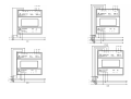
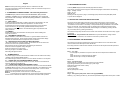
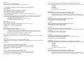
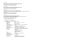
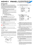
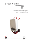
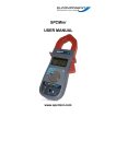
SIRIO
Contatore di energia
Energy meter
ATTENZIONE - La Elcontrol Energy Net S.p.a. declina ogni responsabilità per eventuali
danni a persone o cose originati da un uso improprio o da errato impiego dei propri prodotti.
Soggetto a modifiche senza preavviso.
WARNING – Elcontrol Energy Net S.p.a. declines all liability for any damage to people or
property caused by unsuitable or incorrect use of its products. Elcontrol Energy Net reserves
the right to change product specifications without prior notice.
ATTENTION – Elcontrol Energy Net S.p.a. décline toute responsabilité pour éventuels
dommages à personnes et matériels causées par une utilisation impropre ou par un emploi
des produits incorrect. Elcontrol Energy Net se réserve le droit de modifier sans préavis les
caractéristiques techniques des matériels.
ACHTUNG – Elcontrol Energy Net S.p.a. lehnt jede Verantwortung für eventuelle Schäden
an Personen oder Sachen infolge von unsachgemäßen Gebrauch der Elcontrol-Produkte ab.
Änderungen vorbehalten.
ATENCION – Elcontrol Energy Net S.p.a. declina toda responsabilidad por eventuales
daños a personas o cosas producidos por el uso inadecuado o equivocado de sus productos.
Puede ser modificado sin preaviso.
Unit 5 Southmill Trading Centre, Bishop’s Stortford, Herts. CM23 3DY
T: 01279 503173 F: 01279 654441 E: sales@elcomponent. co.uk
User Manual
English
SIRIO is a three-phase energy analyzer with a 4 modules din-rail case.
The high technological content and its flexibility, make this instrument unique for it’s
quality and performance.
1 - STANDARDS and REGULATIONS - CE Conformity declaration
The SIRIO family of products conforms to Directive 89/336/EEC (EMC), Directive
73/23/EEC - 93/68/EEC (LVD) In compliance with standards IEC 1010-1-400VCat. III
and protection level 2 according to IEC 664-664A (Safety),EN500081-1, EN50082-2 ed
EN55022 (EMC)
1.1 - USER SAFETY
In order to preserve these safety conditions and ensure safe operation, the user
must observe all instructions and marks specified in this user manual.
All maintenance and repair operations requiring the opening of the instrument
must be carried out only by suitably qualified and authorised personnel.
The instrument was shipped from the manufacturing plant in perfect technical
safety conditions.
1.2-SYMBOLS
Please read carefully the instructions with this symbol before installing and
using the instrument.
1.3 - PRELIMINARY INSPECTIONS
Before installation, check that the instrument is in good conditions and was not
damaged during transport. Check that the network voltage and the rated voltage
coincide. This instrument does not require an earth connection.
1.4 - PRECAUTIONS IN THE EVENTS OF MALFUNCTIONS When safe operation is no longer possible, put the instrument out of service and
ensure that it cannot be operated accidentally.
Safe operation cannot be guaranteed in the following circumstances:
When the instrument appears clearly damaged.
When the instrument no longer works.
After long storage in unsuitable conditions.
After being damaged in transit.
2 - POWER SUPPLY
The power supply connections terminals are located on the rear side and are clearly
indicated with the label POWER SUPPLY.
Use cables having a maximum section of 2.5 mm2. Earth connection is not required.
2.1 - CONNECTING VOLTAGE MEASUREMENT CABLES
These cables, having a maximum section of 2.5 mm2, are to be connected to the
terminals labelled VOLTAGE INPUT.
.2.2 - CONNECTING CURRENT MEASUREMENT CABLE
Connect the secondary windings of the external CT's to the 2.5 mm2 terminals labelle
CURRENT INPUT as shown . Use 3 CT's with 5A secondary. Use cables having a sec
appropriate to the length of the connection and the rated power of the CT's used.
Follow the connection diagram at the end of the manual.
NOTE 1: For safety reasons, never leave the CT secondary open.
NOTE 2: To guarantee correct measurements, ensure that the voltage measurement
and the current measurement cables are connected in the same order of phases
3 - MEASUREMENTS PAGES:
At startup SIRIO displays the last selected page before shutdown.
The PAG key is used to browse trough the measurements pages as described in the following.
Page 1: Voltage / Current
Page 2: W / P.F.
Page 3Ê: kWh
Pressing the SEL key while in page 2, the average (AVG) values and the peak (MD) values
of power will be displayed.
4 - PROTECTION CODE FOR THE SETUP PAGES
The access to the setup pages (thus also to the counters reset function and to all setups
necessary for a correct operation of the instrument) can be restricted trough an access code.
To enable the access code it is necessary to keep simultaneously pressed both PAG and SEL
keys for 30 seconds. The code setup page (P. 000000) will be displayed at the end of this
operation. To set up a personal password, select the digits to be edited by pressing the SEL
key, and modify them by pressing the SET key.
The instrument will prompt the user for the access code whenever the access to the setup pages
s requested.
IMPORTANT !!! The password must not be lost. Only the manufacturer, trough a direct
intervention on the instrument, can unlock the instrument’s protection code.
5 - PROGRAMMING THE INSTRUMENT
The instrument can be fully programmed by means of the SETUP menu. Press at the same
time the PAG and the SEL keys to enter the SETUP.
If the setup protection code has been enabled, the instrument will request the access password.
6 - SETUP PAGES:
Pag. 1 - C.T. page
On this page it is possible to set up the current ratio of the amperometric transformers
used.
Press the SEL key to select the digit to be edited.
Press the SET key to modify the selected digit.
Press PAG:
Pag. 2 - Connection page
On this page the connection type of the instrument can be selected.
By pressing the SET key the connection type cycles trough
STAR (three phase with neutral 4 wires),
2PH (two phase),
1 PH (single phase),
DELTA (three phase 3 wires).
Press PAG:
Pag. 3 - Average and peak power values reset page (RESMEd).
Selecting Y, by pressing the SET key, will reset the peak and average values of the power measure.
Press PAG:
Pag. 4 - Counter reset page (RESCNT)
Selecting Y, by pressing the SET key, will reset the kWh counter.
Press PAG: exits setup menu for SIRIO, continues to point 5 for SIRIO with
485-ALM option.
Pag. 5 - RS-485 communication parameters setup page
Press the SEL key to select the parameter to be edited.
Press the SET key to modify the selected parameter.
The first digits from left are the Baud rate (transmission speed). Possible values are:
9.6, 19.2, 2.4, 4.8 (kbaud).
The central digit is the parity check and can have the following values: N (None), O (Odd), E (Even).
The digits to the right represent the type of Modbus communication protocol. Possible values are:
•
IEE (Modbus IEEE standard INTEL format);
•
ASC (Modbus ASCII with emulation of Vip Energy data format);
•
BCD (Modbus BCD MODICON protocol).
Pag. 12 - Selection page of the measurement to be associated to relays output 1.
Press the SET key to select the measurement to be associated to relays output 1 out of the following:
·
V (voltage)
·
A (current)
·
W (power)
·
PF (power factor)
·
RLY (relays remote control via Rs485).
Press PAG:
Pag. 13 - Selection page of the operating mode for relays output 1.
Press the SET key to choose one of the following 2 operation modes:
·
LEVEL (the relays closes and remains closed until the alarm condition terminates);
·
PULSE (the relays generates a pulse with fixed 100ms width upon start of the alarm conditio
Press PAG:
Pag. 14 - Set up of the upper alarm threshold for digital output 1.
Press the SEL key to select the digit to be edited.
Press the SET key to modify the selected digit.
Press PAG:
Pag. 6 - Address setup page.
On this page the RS-485 network address of the SIRIO instrument can be set.
Press the SEL key to select the digit to be edited.
Press the SET key to modify the selected digit.
Press PAG:
Pag. 15 - Set up of the lower alarm threshold for digital output 1.
Press the SEL key to select the digit to be edited.
Press the SET key to modify the selected digit.
Press PAG:
Pag. 7 - Digital outputs selection page.
Press the SET key to select one of the following 3 options:
•
0.10 SEC (Pulse type output with 100 ms pulse width). Press PAG to continue to point 8.;
•
0.02 SEC (Pulse type output with 20 ms pulse width). Press PAG to continue to point 8.;
•
oUT RLY (relays type output). Press PAG to continue to point 12.
Press PAG:
Pag. 16 - Set up of the alarm hysteresis for digital output 1.
This value is expressed as (%) percentage of the alarm threshold. Possible values are between
00 and 99.
Press the SEL key to select the digit to be edited.
Press the SET key to modify the selected digit.
Pag. 8 - Power measurement to be associated to output 1 page.
Press the SET key to choose between kWh and kVAh. The selected power measure will be associated
to output 1.
Press PAG:
Pag. 17 - Set up of the alarm delay for digital output 1.
The delay time is expressed in seconds. Possible values are between 000 and 999.
Press the SEL key to select the digit to be edited.
Press the SET key to modify the selected digit.
Press PAG:
Pag. 9 - Power measurement to be associated to output 2 page.
Press the SET key to choose between kWh and kVAh. The selected power measure will be associated
to output 2.
Press PAG:
Pag. 10 - Pulse value to be associated to output 1 page.
On this page the value associated to each pulse from output 1 can be selected.
Press the SEL key to select the digit to be edited. («K» for editing the exponent)
Press the SET key to modify the selected digit.
Press PAG:
Pag. 11 - Pulse value to be associated to output 2 page.
On this page the value associated to each pulse from output 2 can be selected.
Press the SEL key to select the digit to be edited. («K» for editing the exponent)
Press the SET key to modify the selected digit.
Press PAG:
Pag. 18 - Selection page of the measurement to be associated to relays output 2.
Press the SET key to select the measurement to be associated to relays output 2 out of the following:
·
V (voltage)
·
A (current)
·
W (power)
·
PF (power factor)
·
RLY (relays remote control via Rs485).
Press PAG:
Pag. 19 - Selection page of the operating mode for relays output 2.
Press the SET key to choose one of the following 2 operation modes:
·
LEVEL (the relays closes and remains closed until the alarm condition terminates);
·
PULSE (the relays generates a pulse with fixed 100ms width upon start of the alarm conditio
Press PAG:
Pag. 20 - Setup of the upper alarm threshold for digital output 2.
Press the SEL key to select the digit to be edited.
Press the SET key to modify the selected digit.
Press PAG:
Pag. 21 - Setup of the lower alarm threshold for digital output 2.
Press the SEL key to select the digit to be edited.
Press the SET key to modify the selected digit.
Press PAG:
Pag. 22 - Setup of the alarm hysteresis for digital output 2.
This value is expressed as (%) percentage of the alarm threshold. Possible values are between
00 and 99.
Press the SEL key to select the digit to be edited.
Press the SET key to modify the selected digit.
Press PAG:
Pag. 23 - Setup of the alarm delay for digital output 2.
The delay time is expressed in seconds. Possible values are between 000 and 999.
Press the SEL key to select the digit to be edited.
Press the SET key to modify the selected digit.
. Press PAG: exits the setup menu
7 - TECHNICAL CHARACTERISTICS
·
·
·
·
·
·
·
·
·
·
·
·
Measures
Power supply
Consumption
Display
Voltmeter inputs
Voltmeter input impedance
Number of scales
Current inputs
Current inputs overload
Measurements
Accuracy
Connection
·
·
·
·
·
·
Weight
Protection level
Temperature range
Relative humidity range
Condensation
Digital outputs
70 x 58 x 90 mm
230 or 115 Vac 10%; 35 400 Hz
3 VA
LCD 128 segments
250 Vac phase-neutral; 450 Vac phase-phase
2 Mohm
1 scale for voltage; 2 scales for current
5 A (external C.T.s required); 1 VA
7 A permanent; 15 A for 1 second.
T.R.M.S. (true R.M.S.) up to the 25th harmonic.
1% for V and I; 2% for power (Class 2 IEC 1036)
Single-phase;
three-phase STAR(4 wires);
three-phase DELTA(3 wires);
two-phase + neutral
0.3 kg
Instrument IP20; front panel IP60
-10 +60 °C
20% 80%
non condensing
1 electronic relays 120mA/100Vac +
1 electromechanical relay 1A/250Vac