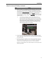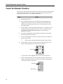
1
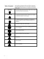
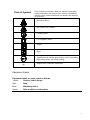
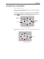
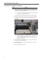
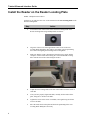
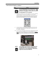
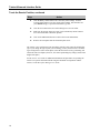
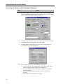
Title: ( BIO-RAD LOGO-B/W) Creator: Twister/Ultramark Interface Guide P/N 400-0175 Copyright This document is published by Bio-Rad Laboratories. Copyright 1999 Bio-Rad Laboratories. All rights reserved. Reproduction in whole or part is prohibited. Trademarks The Bio-Rad logo is a registered trademark of Bio-Rad Laboratories. Twister is a trademark of Zymark Corporation. Ultramark is a trademark of Bio-Rad Laboratories, Inc. Microsoft is a registered trademark of Microsoft Corporation. Windows is a trademark of Microsoft Corporation. All other trademarks and registered trademarks are property of their respective holders. Contents The information in this document may contain typographical errors or technical inaccuracies and is subject to change without notice. Modifications and additions may also be made to the products described in this document at any time. Statement of Proper Use WARNING The Twister/ Ultramark Interface Kit is designed to integrate the Twister Universal Microplate Handler with Bio-Rad's Ultramark microplate reader. The Interface Kit includes the hardware components necessary to physically attach the two instruments to each other, and the software components necessary for the two instruments to run in conjunction from a single personal computer (PC). Do not use this kit to integrate any other microplate instrument with the Twister. Use this product only in the manner described in this manual. When used other than as specified, the safety protections may be impaired. NOTE Contact Us Changes or modifications to this equipment not expressly approved by the party responsible for compliance could void the user’s authority to operate the equipment. Bio-Rad Technical Services Department Open Monday–Friday, 8:00 a.m. to 4:00 p.m., Pacific Standard Time. Phone: (800) 424-6723, option 2, option 3 (510) 741-6576 Fax: (510) 741-5802 E-mail: [email protected] (U.S.) [email protected] (International) iii Table of Symbols These symbols are intended to draw your attention to particularly important information and alert you to the presence of hazards as indicated. Some of these symbols may not appear in the manual or on the product: DANGER An imminently hazardous situation, which, if not avoided, will result in death or serious injury. WARNING A potentially hazardous situation, which, if not avoided, could result in death or serious injury. NOTE A cautionary statement, operating tip, or maintenance suggestion that may result in instrument damage if not followed. Hazardous voltage, risk of shock injury. Risk of body parts, hair, jewelry or clothing getting caught in a moving part. Risk of puncture injury. Risk of eye injury; wear safety glasses. Risk of fire. Risk of poison. Risk of explosion. iv Table of Symbols These symbols are intended to draw your attention to particularly important information and alert you to the presence of hazards as indicated. Some of these symbols may not appear in the manual or on the product: Hazardous fumes. Hot surface, risk of burns. Ground symbol. CE compliance mark. Output. Input. Signifies that the unit has passed safety tests for grounding, high voltage spikes and voltage leakage. F Helpful hints, additional information. Equipment Labels Equipment labels are color coded as follows: Yellow: Caution, risk of danger Red: Stop Blue: Mandatory action Green: Safe condition or information v Table of Contents 1. INTRODUCTION..................................................................................................1 PREINSTALLATION REQUIREMENTS .......................................................................................2 Tools Required ...............................................................................................................2 Space Required..............................................................................................................2 ASSEMBLY OVERVIEW .........................................................................................................2 2. INSTALLATION ...................................................................................................3 INSTALLATION W ARNINGS ....................................................................................................3 INSTALLATION NOTES...........................................................................................................3 UNPACK THE INTERFACE KIT ................................................................................................4 PARTS LIST .........................................................................................................................4 ASSEMBLE THE LOCATING PLATES ........................................................................................5 INSTALL THE READER ON THE READER LOCATING PLATE........................................................8 ADJUST THE INSTRUMENT POSITIONS..................................................................................10 TEACH THE READER POSITION ...........................................................................................12 3. EXERCISING THE TWISTER AND ULTRAMARK............................................15 4. GLOSSARY .......................................................................................................19 5. INDEX ................................................................................................................21 vii 1. Introduction This manual describes the installation and operation of the Twister/Ultramark Interface Kit. The Interface Kit contains the hardware components to run the Twister in conjunction with the Ultramark. Using the Twister with the reader provides automated reading of microplates and stacking and restacking options not available when using the reader as a standalone unit. This Interface Guide is intended as a reference guide for the user of the Twister/Ultramark Interface Kit. It describes only the hardware contained in the Interface Kit. You should be familiar with the operation of the microplate reader and you should have installed and trained the Twister before installing the Interface Kit. For information on installing and operating the Twister and Ultramark, refer to the Twister User Guide, Ultramark User Manual, and Microplate Manager User Guide. Before installing this interface kit, install and configure the Twister according to the instructions in Twister User Guide. Also install and configure the Barcode Reader and/or Extended Capacity Kit, if purchased. After the Twister and any accessories have been installed, follow the instructions in this manual to install the Interface Kit. 1 Twister/Ultramark Interface Guide Preinstallation Requirements Tools Required The following tools are required to install the Twister/Ultramark Interface Kit: Long Phillips head screwdriver Twister Calibration Block (included with the Interface Kit) Space Required The Twister should be assembled in its permanent position on a sturdy lab bench with at least three electrical outlets nearby. After the Twister is assembled, the Ultramark can be connected to the Twister using this Interface Kit. NOTE The bench top must be flat and sturdy enough to support the weight of the computer, Twister, and microplate reader without sagging. An uneven surface will result in the misalignment of the reader and the Twister. For the Twister and the reader, you need an area approximately: 36 in. (92 cm.) wide, 28 in. (72 cm.) deep, and 19 in. (49 cm.) high. In addition, you must provide adjacent space for the computer and (if applicable) the Twister Extended Capacity platform. Assembly Overview After the Twister has been assembled (following the instructions in the Twister User Guide) and any accessories (e.g., Barcode Reader, Extended Capacity) have been installed, use the Twister/ Ultramark Interface Kit to connect the Twister to the reader according to the following procedures: 1. 2. 3. 4. 5. 2 Unpack the Interface Kit Assemble the locating plates Install the reader on the Reader Locating Plate Adjust the instrument positions Teach the Reader Positions 2. Installation Installation Warnings WARNING Turn OFF power to the Twister, Ultramark, and computer before beginning these procedures. Use only the tools listed in this manual to perform the steps described in the instructions. Never perform any operation on the instrument in an environment where potentially damaging liquids or gases are present. Installation Notes NOTE Do not loosen/tighten any screws or touch parts other than those specifically designated in the instructions. Doing so may cause misalignment and could void the instrument warranty. Never force any component to fit if it will not do so easily. 3 Twister/Ultramark Interface Guide Unpack the Interface Kit Step Action 1 Inspect the shipping carton for damage. 2 Remove all components from the box and verify that all parts are contained in the carton. (See the Parts List below.) If any parts are missing, contact Bio-Rad. See Contact Us at the beginning of this manual for more information. 3 Retain the carton and packing materials. If the contents should need to be returned for repair, use the original packing materials and carton for shipping. If the carton has been damaged in transit, it is particularly important to retain it for inspection by the carrier in case there has been damage to the contents. Parts List The Twister/Ultramark Interface Kit includes the following items: Reader locating plate with mounting hardware Twister/Ultramark Interface Guide (this document) 4 Installation Assemble the Locating Plates Tools: Phillips head screwdriver In this step, you will align the Reader Locating Plate with the Twister Locating Plate and fasten them loosely with two screws. First, decide on the configuration of the Twister and the Ultramark. The most efficient configuration is with the Ultramark on the left side of the Twister. (See figure below.) This is the preferred configuration. If you have purchased the Extended Capacity Kit, the Extended Capacity will then be located on the right side of the Twister. Lid Storage Platform Extended Capacity (optional) Ultramark Front Preferred Configuration If this configuration is unacceptable, you can locate the Ultramark on the right side of the Twister. Ultramark Front Optional Configuration 5 Twister/Ultramark Interface Guide Assemble the Locating Plates, Continued Step Action 1 Make sure that the Twister is attached to the Twister Locating Plate (see the Twister User Guide for instructions). Place the Reader Locating Plate on the desired side of the Twister Locating Plate. F The most efficient configuration based on the Twister's arm movement is with the reader to the left of the Twister. The offset edge of the reader plate should point towards the Twister plate. 2 Slide the offset edge of the reader plate over the Twister plate, centering the two holes in the reader plate over two of the three threaded inserts on the Twister plate. F 6 If the microplate reader is on the left side of the Twister, use the two inserts toward the front of the Twister plate (see figure above); if the reader is on the right side of the Twister, use the two inserts toward the back of the Twister plate. 3 Remove the plate mounting hardware (two screws, two small washers, and two large washers) from the plastic bag. 4 Place one large washer over each of the two threaded inserts, on top of the Reader Locating Plate. 5 Place one small washer on each screw. Installation Assemble the Locating Plates, Continued Step 6 Action Thread a screw into each threaded insert. Do not fully tighten the screws. The two plates should slide loosely within the limits of the screws. Screw Small Washer Twister Large Washer Device Locating Plate Twister Locating Plate Assembling the Locating Plates 7 Twister/Ultramark Interface Guide Install the Reader on the Reader Locating Plate Tools: Phillips head screwdriver In this step, you will place the "feet" of the Ultramark in the Foot Locating Disks on the Reader Locating Plate. Step 8 Action 1 Loosen the screws in the centers of the four Foot Locating Disks on the Reader Locating Plate using a Phillips head screwdriver. 2 Align one of the screws in the approximate center of one of the Foot Locating Disks and tighten. This will be your anchor point for positioning the Twister and aligning the remaining Foot Locating Disks. 3 Make sure that the reader is disconnected from the power supply and the computer. Lift the reader and carefully place it onto the Reader Locating Plate with the front of the reader facing the Twister. 4 Adjust the Foot Locating Disks so the feet of the reader rest in the center of each disk. 5 After you have properly aligned the disks, carefully lift the reader off the plate, being sure to not move the disks. 6 Tighten the screws in the center of each disk, once again being careful not to move the disks. 7 Place the reader back on the plate and check the positioning of the Foot Locating Disks. Readjust as necessary. Installation Install the Reader on the Locating Plate, Continued Step Action 8 When the reader is correctly positioned on the locating plate, plug the reader’s AC power cord into a grounded, 100-240V AC power outlet. (Ensure the fuse configurations are correct.) 9 Attach the reader's communications cable from the back of the reader to the back of the computer. (See the reader documentation for reader setup instructions.) WARNING 10 Do NOT connect the reader communication cable to the back of the Twister! Improper connections may cause permanent damage to the instruments. Complete the setup of the reader by following the instructions in the Ultramark User Manual and Microplate Manager User Guide. NOTE Verify that all communications cables and power cords are securely plugged into the Twister, the computer, and the reader. 9 Twister/Ultramark Interface Guide Adjust the Instrument Positions Tools: Long Phillips head screwdriver In this step, you will adjust the position of the reader so the Twister can place plates correctly in the reader's plate carrier. Step 1 Action Turn ON the reader and press the Open/Close button to open the reader drawer. Make sure that the drawer is fully open and the plate carrier is fully extended before performing the following steps. F 2 Place the Twister Calibration Block in the reader plate carrier, with the cutouts in the block facing up. NOTE The following steps will be much easier if two people perform them: one to hold the gripper and the other to adjust the position of the Ultramark. 3 With the Twister switched OFF, manually move the Twister arm around so that it is positioned over the calibration block. 4 Release the Twister arm so that it drops slowly onto the calibration block. Note approximately how much plate adjustment will be required so that the gripper fits inside the cutouts on the calibration block. Then move the arm up and out of the way. NOTE 10 If the plate carrier moves while adjusting the instrument position, press the Open/Close button twice to return the plate carrier to the fully extended position. The following step is critical to ensure the proper transfer of plates between the Twister and the reader. Installation Adjust the Instrument Positions, Continued Step Action 5 Make sure that the screws attaching the Reader locating plate to the Twister plate are loose. Move the reader and its locating plate forward and back and side to side. Rotate the Twister arm back over the plate carrier and let it drop onto the calibration block. Repeat this procedure until the gripper drops into the cutouts of the calibration block. Note that the gripper should free fall directly into the cutouts (because the cutouts are snug, a slight tap may be required for the gripper to fit). Also, the gripper fingers should be an equal distance from the sides of the calibration block. F If you cannot get the gripper to align with the calibration block by moving the Reader Locating Plate, you can loosen the Foot Locating Disks on the plate, thereby gaining additional room for adjustment. First lift the reader out of the Foot Locating Disks, then loosen all the disks, place the reader back in the disks, and attempt to realign. When the calibration block is aligned with the gripper, lift the reader out of the disks and retighten them in the new position. 6 Press the Open/Close button on the reader twice again to confirm that the plate carrier is in the fully extended position, then verify that the gripper still drops into the calibration block. 7 When the instruments are aligned, move the Twister arm up and out of the way, then carefully and firmly tighten both screws on the Reader Locating Plate. Be careful not to move the plate! Repeat step 6 above for final confirmation. Replace the Calibration Block with a default microplate in the reader plate carrier for the next procedure. 11 Twister/Ultramark Interface Guide Teach the Reader Position In this step, you will teach the vertical and rotary offsets for the reader. You must have the Twister software installed on your computer and be familiar with its operation before proceeding. (See the Twister User Guide for instructions.) Step Action 1 Switch ON the Twister. 2 Insert a default microplate (the same kind used to trained the Input and Output racks) in the plate carrier, if you haven't already. With the reader still ON, press the Open/Close button twice to ensure the drawer is in the fully open position. 3 On the computer, click on the Windows Start button, go to Programs, select Bio-Rad Twister Plate Handler, and select Twister. (To open the Twister control panel from within Microplate Manager, see the Microplate Manager User Guide.) 4 In the Twister Main Menu, click the Manual Control button. The manual positioning control panel will open. 5 If you are positioning the Twister arm for the first time, select "defaults" in the Plate Type textbox. F 6 Ensure that the Absolute Positioning checkbox is NOT selected. If your reader is on the left side of the Twister, click on Position 2 on the Rotary Positioning Diagram to move the arm to position 2. Position 2 (If your reader is on the right side of the Twister, click on Position 6.) 7 Under Vertical Positioning, go to the diagram and click the down arrow or drag the scroll bar down to lower the arm. Lower the arm to approximately ¼ inch above the plate in the drawer. Scroll bar Down arrow 12 Installation Teach the Reader Position, continued Step Action NOTE The following steps will be much easier if two people perform them: one to observe the position of the gripper and the other to control the adjustment on the computer. 8 Under Rotary Positioning, click on the adjustment arrows next to the Rotary Adjustment field to move the arm horizontally above the microplate. Position the gripper so the fingers appear perfectly centered over the plate. Note that the plate should already be well centered with the Twister arm, based on your earlier alignment of the Twister and reader locating plates. 9 Click the Find Plate button. The gripper should drop down onto the plate, and the gripper fingers should be an equal distance from the sides of the plate. This is a critical step. 10 To test your rotary positioning, click on the Close Gripper button to grip the plate. If your rotary positioning is precise, the plate should move only very slightly when you grip it. If the plate moves, open the gripper, lift the arm slightly using the Vertical Positioning controls, and then repeat steps 8 and 9 above. NOTE If the gripper will not center on the plate after repeated attempts at rotary positioning, the instruments are out of alignment. Go back to Adjust the Instrument Positions. 13 Twister/Ultramark Interface Guide Teach the Reader Position, continued Step Action 11 Click the Rotary Offset button to save the rotary offset settings. Click the Vertical Offset button to save the vertical offset settings. Note that these are your default settings, as specified in the Plate Type box. 12 Click the Yes button in the Save Offset dialog box to save the offset. 13 Make sure the gripper fingers are open. Click on the Rotary Home button to move the Twister arm to the home position. 14 Click on the Main Menu button to return to the Twister Main Menu. 15 Remove the microplate from the Ultramark plate carrier. The Twister is now configured to run microplates with the reader, using the default plate type. If you change the type of plate you are reading, you may need to create a new Plate Type setting in the Twister control panel. (Note that the Twister's rotary positioning will remain the same for all plates; however, the vertical positioning may change, based on the height of the plate.) See the Twister User Guide for additional information and procedures for operating the Twister. For specific information about using the Ultramark in conjunction with the Twister, see the Microplate Manager User Guide. 14 3. Exercising the Twister and Ultramark After the Twister and Ultramark have been connected and the Ultramark plate carrier position has been trained, you are ready to perform an exercise run. Bio-Rad's Twister and Ultramark are both operated through Bio-Rad's Microplate Manager software. Microplate Manager is included with the Ultramark and should be installed when you install the Ultramark. See the Microplate Manager User Guide for complete instructions on installing and using Microplate Manager in conjunction with the Ultramark and the Twister. The steps required to perform an exercise run are provided below. Step Action 1 Press the Power Switch on the back of the Twister to the ON position. The green power light on the front of the Twister will be illuminated, indicating the Twister is ON. WARNING When the Twister is switched ON, the Twister arm will move to the vertical and horizontal home positions. Ensure you are out of the way of the arm before switching ON the Twister. 2 Switch ON the computer and the Ultramark, if they are not on already. 3 Load at least one standard empty microplate in the Input rack on the Twister. If you have installed the Extended Capacity racks, load at least one empty microplate in each of those as well. Be sure to leave the Output rack empty. F 4 Make sure you are using the same type of microplate in all the positions. On the computer, click on the Windows Start button, select Programs, then the Microplate Manager folder, then the Microplate Manager application icon. 15 Twister/Ultramark Interface Guide Exercising the Twister and the Ultramark, Continued Step Action 5 Microplate Manager will open. From the File menu, select New Multiple Plate Protocol. The Multiple Endpoint Protocol dialog box will open, and the Stack Loader checkbox at the bottom will appear checked. 6 At the bottom of the dialog box, type "test" into the Filename field. Then click on the Run button in the upper right corner of the dialog. 7 The Plate Handler Options dialog box will open. This is the interface for controlling the Twister and its accessories. 8 For a complete exercise run, select all the options that apply: • • • • 16 If you are using the Lid Storage Platform, select either Lid on Top Plate ONLY or All Plates Have Lids under Lid Configuration. If you have installed the Extended Capacity, check the Use Extended Capacity checkbox. If you have installed the Barcode Reader, check the Scan Barcode checkbox. Select whatever Restacking Option you prefer. Exercising the Twister with the Ultramark Exercising the Twister and the Ultramark, Continued Step Action 9 Make sure the Plate Type specification is set to Defaults. Then click on the OK button to begin the exercise run. NOTE Once a run is started: Do not add or remove plates from either the input or output racks. Do not interfere with the movement of the Ultramark plate drawer or the Twister arm. WARNING If the Twister stops with a microplate in the gripper, do not turn the Twister power off without holding the microplate or the Twister will drop the microplate. WARNING Always keep body parts, hair, jewelry, and clothing away from the Twister while it is operating. The Twister arm may move unexpectedly. Keep all objects out of the path of the Twister arm. If the Twister arm encounters an object in its path, the Twister will lose the proper orientation. 10 While the exercise run is proceeding, closely observe all the positions you are exercising. The gripper should not touch the sides of the racks, and should pick up and put down plates smoothly and without jarring. The plates should be properly centered in the plate carrier of the Ultramark. 11 When the run is complete, confirm that the plates have been placed in the proper racks based on the Restacking Option you selected. You do not have to save the results of this run. You can simply exit Microplate Manager. 17 4. Glossary Drawer The reader's microplate drawer. Calibration Block A microplate-sized block with cutouts used to align the Twister with the Ultramark. Extended Capacity The Twister with the Extended Capacity Kit installed has a capacity of up to 80 microplates without lids, or up to 60 microplates with lids. Toppers can be used on the microplates without lids. This configuration uses 5 racks (4 input racks and one output rack). Lid A flat cover placed on top of a microplate to prevent evaporation and/or contamination of the samples in the plate. Twister can process plates with a lid on each plate or with a lid only on the top plate in the stack. F When using a lid only on the top plate, the lower plates in the stack are protected by the plate above them. Locating Plates Plates on which the Twister and the Ultramark are mounted. These are used to position the two instruments relative to one another and connect them. Rotary Home The Twister arm's furthest position of travel in a clockwise direction. Standard Capacity The standard capacity of the Twister is up to 20 microplates without lids, or up to 15 plates with lids. A topper can be used on the stack of 20 microplates. This configuration uses 2 storage racks (one input rack and one output rack). Storage Rack An aluminum rack used to store microplates. Topper A lid or an empty microplate placed on the top of a stack of microplates to prevent evaporation and/or contamination of the samples in the top plate. F When using a topper on the stack of microplates, the lower plates in the stack are protected by the plate above them. Vertical Home The Twister arm's highest vertical position. 19 5. Index A Assembly Locating Plates ............................................... 4 Overview ........................................................ 2 B Bio-Rad ............................................................. iii C Contact Us......................................................... iii D Damage .............................................................. 3 F Foot Locating Disks ........................................... 5 G Gripper ............................................................... 6 I Installation Notes .............................................................. 1 Reader ............................................................ 5 Warnings ........................................................ 1 Instrument Positions Adjusting........................................................ 6 Introduction........................................................ 1 L Locating Plates Assembly........................................................ 4 M Manual Control Button ...................................... 7 P Parts List ............................................................ 3 R Reader Communications Cable .................................. 5 Installation...................................................... 5 Power Cord .................................................... 5 Reader Locating Plate ................................ 4, 5, 6 Reader Position Teaching......................................................... 7 Required Space .............................................................. 2 Tools .............................................................. 2 S Space.................................................................. 2 T Teach the Reader Position.................................. 7 Tools .............................................................. 2, 4 Twister Locating Plate ....................................... 4 U Unpack the Interface Kit .................................... 3 V Vertical Offset Button ........................................ 8 21