1
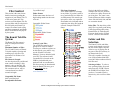
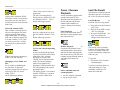
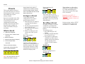
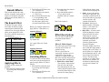
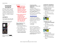
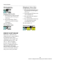
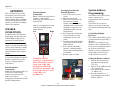
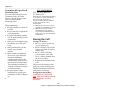
 Kanati Tek
Digital Game Calling system
CX & PX Series
Owner’s Manual
Web Revision B
Introduction ………………………………………………………………………………………………………………. www.KanatiTek.com Fill out the Contact Us form and place your question in the Body part of the Thank you for purchasing the
message form. Be sure to put the Kanati Tek Digital Game
phrase “Support Question” in the Calling System.
Subject box of the form. Table of Contents Introduction Product Registration If you purchased your Kanati Tek
product at the Kanati Tek online
store, the product was
automatically registered so the
product registration is complete.
If you purchased your Kanati Tek
product at a retailer other than the
Kanati Tek online store at
www.KanatiTek.com, then
product registration by mail is
required. This can be
accomplished by completely
filling out the registration form on
the back cover of this manual, and
sending in a photocopy of this
form with a photocopy of the
original sales receipt within 30
days of the purchase date. The
address is on page 36 of this
manual.
Contact Kanati Tek Introduction…………. 1 Product Registration…….. 1
Contact Kanati Tek……… 1
Safety Precautions………. 1
Table of Contents……….. 1
SAFTEY PRECAUTIONS: Getting Started.......... 2 1. Never operate the game call
indoors or point the speaker
directly at any person. These
products are extremely loud and
can cause hearing damage if
used improperly.
2. Remove the battery or
batteries from the game call
unit before charging. Charge
the battery or batteries in a
location away from flammable
materials, open flames, personal
property or persons. Never
leave any charging battery and
charging equipment unattended!
3. Remove the batteries or
battery from the charging
device as soon as the charge
cycle is complete.
4. Keep all Kanati Tek products
away from children and pets.
Step 1: Unpack & Check... 2
Step 2: Charge Batteries... 2
Step 3: Install Batteries….. 2
Step 4: System Parts…….. 3
Step 5: Powering Up…….. 5
Step 6: Play a File……….. 6
File Control……..........7 The Kanati File System…. 7
Folder & File Selection….. 7
Pause / Play..……………..8
Last File Recall………….. 8
Volume Control........9 Volume Up/Down……….. 9
Mute…………….......... ….9
SET V Steps……………... 9
Balance Control…............ 9
Presets……….……….. 11 What Is Saved………........ 11
Saving to a Preset…….......11
Recalling a Preset……….. 11
Kanati Effects........... 12 Contact Kanati Tek support with questions regarding the use of this product at: The Kanati Effect….......... 12
Applying Effects.............. 12
Cancelling Effects………. 12
1 Kanati Tek Digital Game Calling System Owner’s Manual Effect Descriptions………12
Auxiliary Outputs....15 Outputs.............................. 15
Decoy Fast / Slow…......... 16
Appendix………..........17 Speaker Connections….....17
Address Programming…...17
Maximizing RF Range......18
FCC Statement………….. 19
Storing the Call…………..19
Troubleshooting……….... 20
Limited Warranty……….. 21
Legal Statements………... 21
Getting Started ………………………………………………………………………………………………………………. Model PX-1
Qty
Item
1
Receiver Base Unit
This section is a quick start
1
Remote Transmitter
guide for your Kanati Tek CX
1
USB Flash Drive / 35
or PX model Digital Game
Free Sounds Loaded
1
Decoy
Servo Motor
Calling System. Refer to the
1
Machined Motor Coupler
sections following this Getting
1
Kanati Decoy Topper
Started section as they provide
1
Topper
Rod Set
more detailed user information.
1
8 Cell Battery Holder
1
Printed
User Manual
Step 1: Unpack & 1
Internal HQ Speakers
Getting Started Check 1. Remove Your New Unit from
the package
2. Open the Receiver case and
remove any packaging
materials from the inside.
3. On the larger PX series the
remote and smaller
accessories will be packed
inside the receiver unit.
4. Check Package Contents. See
the following chart for your
model and the “Standard”
included parts:
All CX Series
Qty
Item
1
Receiver Base Unit
1
Remote Transmitter
1
USB Flash Drive / 35
Free Sounds Loaded
1
Printed Users Manual
1
Tether & Unit Stand
Step 2: Charge the Batteries Step 3: Install Batteries 1. Battery charging method used
will depend on the model
purchased.
1. On all models switch the
receiver power switch to the
off position (0).
2. For CX & PX-1 models,
charge individual AA cells in
the optional Charger /
Analyzer system. Kanati #
KTBK1
2. On CX and PX-1 models
install the individual AA cells
in the receiver battery tray(s)
in the proper direction
3. For PX-2 & PX-3 Models use
the supplied dual stage 12V
battery charger.
Model PX-2
Qty
Item
1
Receiver Base Unit
1
Remote Transmitter
1
USB Flash Drive / 35
Free Sounds Loaded
2
Decoy Servo Motor
2
Machined Motor Coupler
2
Kanati Decoy Toppers
1
Topper Rod Set
1
12V SLA Battery
1
External Battery Charger
1
Printed User Manual
2
Internal HQ Speakers
4. **WARNING: OBSERVE
POLARITY MARKINGS
AND COLORS WHEN
INSERTING BATTERIES IN
A CHARGER OR PLACING
CLIP LEADS ON BATTERY
TERMINALS AND NEVER
LEAVE OPERATING
BATTERY CHARGERS
AND BATTERIES UNDER
CHARGE UN-ATTENDED!!
5. For instructions on each
charger type follow the
supplied charger
manufacturer’s instructions.
Note: Optional accessories are not
listed in the previous charts. If
you ordered options check for
those ordered parts at this time.
2 Kanati Tek Digital Game Calling System Owner’s Manual 3. On PX-2 and PX-3 models
install the 12V sealed lead
acid battery in the case
locking it in place with the
supplied Velcro strips.
Connect the leads: Red to the
(+) positive terminal and
brown or black wire to the (-)
negative terminal.
4. Remove the battery cover on
the transmitter. Install the
battery(s) in the battery tray in
the proper direction. Replace
the battery cover.
5. ***WARNING: NEVER MIX
DIFFERENT BATTERY
TYPES OR BATTERY
MODEL NUMBERS IN THE
SAME UNIT. THIS WILL
CAUSE DAMAGE AND
VOID THE WARRANTY!
Getting Started ………………………………………………………………………………………………………………. Step 4: System Parts CX Series Receiver (External)
•
•
•
•
•
•
•
•
•
PX-1 Receiver (External)
•
•
•
•
•
•
•
•
•
Receiver Antenna
Receiver Status LED
Receiver Power Switch
Decoy Output Jack
Right External Speaker
Left External Speaker
Internal HQ Speaker Heavy Duty Case Tethered Unit Stand CX Series Receiver (Internal) •
•
•
•
•
•
Decoy Rod & Topper
Receiver Antenna
Power Switch
Receiver Status LED
Decoy Output Jack
Right External Speaker
Left External Speaker
Heavy Duty Case
Internal Speaker (Back)
Battery Tray
USB Key Memory
Program Button
Motor Coupler (Option)
Decoy Motor (Option)
Internal HQ Speaker
PX‐1 Receiver (Internal) •
•
•
•
•
•
•
3 Kanati Tek Digital Game Calling System Owner’s Manual Internal HQ Speaker
Battery Tray 1
Battery Tray 2 (Option)
USB Key Memory
Decoy Motor 1
Program Button
Decoy 2 Motor (Option)
Getting Started ………………………………………………………………………………………………………………. PX-2 Receiver (External)
•
•
•
•
•
•
•
•
•
•
Decoy Rod & Topper 1
Decoy Rod & Topper 2
Receiver Antenna
Power Switch
Receiver Status LED
Decoy Output Jack
Right External Speaker
Left External Speaker
PX-2 Internal Speaker 1
PX-2 Internal Speaker 2
(Back)
All CX and PX Series Models
Receiver Control Panel
•
•
•
•
•
Receiver Status LED
Power Switch
Decoy Output Jack
R External Speaker Jack
L External Speaker Jack
PX‐2 Receiver (Internal) •
•
•
•
All CX and PX Series Models
RF Transmitter Control
USB Key Memory
Program Button
Internal HQ Speaker 1
12V Sealed Battery
• Decoy Motor 1
• Decoy Motor 2
• Remote Control and
Decoys Fit Inside
• Internal HQ Speaker 2
4 Kanati Tek Digital Game Calling System Owner’s Manual • Transmitter Antenna
• Large Numeric & Shifted
Functions Keys
• Remote Status LED
• Power On/Off & Function
Shift Key
• File Folder Select Key
• Volume Control Keys
• Pause / Play Key
• Field Lanyard
• User Friendly Color Coded
Keys
Getting Started ………………………………………………………………………………………………………………. All CX and PX Series
‐Numeric 0 Models RF Transmitter
‐Transmitter Address Control
Program Mode Select ‐Numeric 1 ‐Effect Mode Select Step 5: Powering Up. 1. Open the receiver and insert
the USB memory key in the
receiver circuit board USB
port. The key must contain all
100 sequentially numbered
(000-099) sound files on it.
‐Numeric 2 ‐Balance Mode Select ‐Numeric 3 ‐Preset Save Mode Select ‐Numeric 4 ‐Preset 1 Recall ‐Preset 1 Save ‐Numeric 5 ‐Preset 2 Recall ‐Preset 2 Save ‐Numeric 6 ‐Preset 3 Recall ‐Preset 3 Save ‐Numeric 7 ‐Preset 4 Recall ‐Preset 4 Save ‐Numeric 8 ‐Preset 5 Recall ‐Preset 5 Save ‐Numeric 9 ‐Recall last played file and play it All CX and PX Models
Transmitter Keys Detail:
-Pause / Resume
-Out 2 On/Off
‐Volume Down ‐ Mute ‐ Volume Up ‐
Set V Mode Select ‐Folder View/Select ‐Out 1 On/Off ‐Function Mode ‐Hold for 4 seconds to Power On/Off NOTE: For more information see
“The Kanati Tek File System” in
the “Files” section of this manual.
2. Install a fully charged set of
batteries in both the receiver
and transmitter units in the
proper direction.
3. Toggle the power switch on
the receiver from Off to On.
Following a short power up
sequence the receiver LED
should stay on solid. See the
following figure.
4. If the Receiver Status LED
does not stay on solid, then
the LED should be flashing a
code that can be referenced in
5 Kanati Tek Digital Game Calling System Owner’s Manual the Troubleshooting section of
the Appendix.
Note: If the Receiver LED is
flickering quickly while it is not
receiving a transmitter signal, and
the flashes are not at a rate
indicating a trouble code
described in the troubleshooting
section, then this is a warning
indicating LOW RECEIVER
BATTERY VOLTAGE. Charge
the batteries as soon as possible.
5. Power up the transmitter by
holding the “FN” key for
approx 4 seconds.
6. When the “Transmitter Status”
lights solid green you are
ready to go!
Kanati Tip!: Whenever the
transmitter is sending data to the
receiver this LED will flash and if
the receiver is receiving this
information the receiver status
LED will flash too! A flashing
receiver LED when no transmitter
button is pushed, indicates a low
receiver battery.
Getting Started ………………………………………………………………………………………………………………. number. It is not necessary to
Step 6: Playing a re-select Folder 0.
File! Kanati Tip!: No sequence on the
transmitter ever requires two
buttons being pushed at once.
Never push two buttons at once
for any reason, unpredictable
results may occur!
1. A file must be selected before
any other functions are active
on power up.
2. There are 10 files numbered 09 stored in Folders numbered
00-09. That is 100 files total.
3. To play File 0 in Folder 0:
First select Folder 0 by
pressing and releasing the
“FLDR” key, then press and
release the 0 key. To play file
0, hold the “0” key until you
hear the file you have selected
start playing. Here is the
simple sequence:
4. Now that you are in Folder 0,
to play another one of the ten
files in the current Folder 0
simply press and hold that key
5. So to play File 5 in the current
Folder 0, just press and hold 5
to send the play File 5 in
Folder 0 command to the
receiver.
6. Now to play File 7 in the
current Folder 0, just press
and hold the 7 key until you
hear the selected file start
playing.
7. Let’s change folders and play
File 58. That is Folder 5 File
8. It is this easy!!
8. Now to play file 52 just press
and hold 2. Remember you
are currently in Folder 5 so a
folder change is not needed.
6 Kanati Tek Digital Game Calling System Owner’s Manual File Control ………………………………………………………………………………………………………………. CoyoteHowl.mp3
File Control This section is the start of more
detailed sections regarding the
operation of your Kanati Tek CX
or PX series game call. This
section covers the Kanati Tek file
system, folder and file selection in
the field with your Kanati Tek
remote, file control such as Play
and Pause commands, and finally
how to recall the last file played
by the system.
File Setup Continued:
A file name cannot be left empty
in any folder. If you don’t wish to
use a particular file in a folder the
xxxDelayttt.mp3 file must be put
in its place, where xxx equals the
file number to be left blank and ttt
equals the time delay file length in
seconds. Example Folder/File
Setup:
Folder Names:
Folder names must also have a 2
digit leading number in the name
of 00-09.
Compatible Folder Name:
Incompatible Folder Names:
The Kanati Tek File System The Kanati Tek file system is
setup in a simple File Folder
system.
Maximum Number of Files:
The CX and PX series of Kanati
Tek calls capable of storing and
recalling up to 100 files. In a
maximum of 10 Folders of 10
Files each.
File Names & Length:
Are best kept short as possible and
must contain a leading 3 digit
numeric value as 000-099. All
files must contain a compatible
file extension such as .mp3 or
.wma and must be at least 5
seconds in length.
Notice in the 00Coyote folder
example files 003, 005, and 008
are unused so a delay file must be
put in its place. The same is true
for the 01Raccoon folder example
where files 002, 004, 006, and 008
are to remain unused.
Delay Files: The time delay of the
delay files is typically used during
Folder Sequencing while using
Kanati Effect #1 Folder Repeat.
For more detail see the “Kanati
Effects” section of this manual.
Folder and File Selection Setting Up the Files:
The system files must be put in
groups of 10 in the ten folders.
You may use windows explorer to
do this directly or to make it easy,
use the “Kanati Tek Folder
Manager” freeware included with
your call. The software install
executable file is located on the
USB key included with your
purchased call. As an alternative
this freeware may be downloaded
from the Kanati Tek store, go to
the Downloads link at:
The Kanati Tek file and folder
system was designed to provide
the user with a simple, fast and
effective way of playing files in
any part of the call’s memory in
an instant in the field.
This call is capable of storing 10
sets of files numbered 000-099
stored in Folders numbered 00-09,
100 files total. Selecting a folder: To select a
new operating folder, first push
and release the “FLDR” button,
the FLDR LED will light. Now
you have 5 seconds to push a
numeric key 0-9 to select a folder
0-9.
www.KanatiTek.com
Compatible File Name:
005CoyoteHowl.mp3
Incompatible file name:
7 Kanati Tek Digital Game Calling System Owner’s Manual File Control ………………………………………………………………………………………………………………. At the point in which the FLDR
LED starts to flash 3 seconds have
passed and you now only have 2
seconds before the folder selection
mode exits.
Select and transmit a File:
Once a folder is selected the user
may move though any file in the
current operating folder with a
single button push. For example
if the call is currently playing file
# 63, that is Folder 6 / File 3 and
you wish to go to File # 61 then
you only have to push and hold
button 1:
With the call already operating in
Folder 6 File #61 will play.
Changing to a New Folder and
File:
It is as simple as combining the
two functions. So the call is
currently playing File #61 and you
wish to go to File #13, that is
Folder 1 File 3.
Do the following sequence:
Pause / Resume Playback That’s it! Easy isn’t it? Now try
another one.
The call is currently playing
File#13 and you wish to go to File
#6. Which is Folder 0 / File 6.
Do the following sequence:
At any point during playback the
system can be paused. This
function pauses the playback of
the file and shuts off the dual
channel audio amplifiers to
conserve battery power during
pause.
Pause Playback:
To
pause press and hold the Pause /
Resume key until playback stops,
then release the key.
Now let’s jump all the way up to
File #84, which is Folder 8 / File
4.
Do the following sequence:
Resume Playback:
To
resume the file playback: Press
and hold the Pause / Resume key
until the file starts playing again,
then release the key. The file will
continue playing from the point at
which the pause mode was
entered.
To View the Current Operating
Folder:
At any time during the operation
if you need to know which Folder
number the call is currently
operating in, just press the
“FLDR” key to enter the Folder
mode. The current operating
folder will be displayed by
lighting the LED on numeric keys
0-9 corresponding to the current
operating Folder.
The display period is 5 seconds or
until the “FLDR” key is pressed
again to exit the Folder select
mode.
Other commands that will
resume playback:
• Any file selection command
• Any preset file recall
8 Kanati Tek Digital Game Calling System Owner’s Manual Last File Recall This function is a handy function
that allows the user to recall play
the “Last” file played at anytime.
Last File Recall:
To
recall the file previously played
1. Press and release the Function
(“FN”) key.
2. The Left Green LED over the
“FN” key will light.
3. Now press and hold the “#9 /
Last” key until the file
changes, then release the key.
The last file can be in another
Folder or the same folder. If the
last file is in another folder the
system automatically changes the
folder for you!
To go back:
1. Execute the “Last” function
command again.
Try this several times until you
will get the hang of it. Just
remember to push the “FN”
button first each time.
Volume Control ………………………………………………………………………………………………………………. playback will continue. If you
wish to stop playback use the
This section covers all of the
Pause / Resume feature described
features of your Kanati Tek digital
in the previous section.
calling system that relate to
controlling the playback volume.
Muting:
To send the Mute command:
1. Press and release the “FN”
Volume Up /Down key.
This function controls the volume
2.
The
left green LED should be
like the volume knob on a home
lit
over
the “FN” key.
stereo or car radio. By ramping
3. Now within 5 seconds press
the volume Up or Down as the
and hold the “Volume Down /
volume Up or Down keys on the
Mute” key until you hear the
remote are held until the desired
volume go to zero.
volume is reached.
Volume Control Turning Up the Volume:
To increase the playback volume:
1. Press and hold the Volume Up
arrow key during file
playback until the desired
volume level is reached.
Turning Down the Volume:
To decrease the volume:
1. Press and hold the Volume Up
arrow key until the desired
volume level is reached.
volume the playback is currently
at. To solve this problem we have
developed a volume preset feature
we call “Set V”. This breaks up
the whole volume range of the
system into 9 preset or known
volume steps 1 – 9.
STEP
0
1
2
3
4
5
6
7
8
9
Selecting a “Set V” step:
To select one of the 9 “Set V”
steps enter the Function mode by
pressing and releasing the “FN”
key, the amber light should light
over the “FN” key. Now within 5
seconds press and release the “Vol
Up / Set V” key then press and
hold a numeric key 1-9 until you
hear the volume change.
Un-Muting:
To send the Un-Mute command:
1. Press and release the “FN”
key.
2. The left green LED should be
lit over the “FN” key.
3. Now within 5 seconds press
and hold the “Volume Down /
Mute” key until you hear the
volume go to pre-mute level.
Mute Playback This function causes the playback
volume to go to zero but the file
% Volume Level
9%
13%
28%
38%
47%
56%
66%
75%
84%
94%
Balance Control “SET V” Volume Balance control provides the
ability to control the volume to the
Left and Right audio outputs
independently. Useful in stereo
Kanati Tek understands that you
will not always be close enough
the receiver unit to hear what
9 Kanati Tek Digital Game Calling System Owner’s Manual files with two different sounds
split over the left and right
channels of the audio file. The
user can select how loudly of each
sound plays back by controlling
the balance between the left and
right channel.
Kanati Tip!: Setup commonly
with two different animals
battling. The user then controls
the balance “to set the scene” of
the battle.
The balance range:
Balance
Key
Full Left
Center
(Default)
Full Right
Setting Balance:
To set the system balance first
select the Balance function mode,
then a numeric value 1-9
corresponding to the table above.
In this example let’s set full left,
so the left channel is at 100%
volume and the right channel is at
0% volume.
Volume Control ………………………………………………………………………………………………………………. Full Left:
Even more right step 3:
Now try these balance levels:
Full Right:
Return to Center:
Now try moving the balance Left
a step at a time:
Partial left step 1:
More left step 2:
Even more left step 3:
Full Right!:
Now return the balance back to
center:
Return back to center:
Viewing the Current Balance
Level:
To view the current balance level
during operation just put the unit
into the balance function mode
and the current balance level will
be display on the numeric key
LEDs 1-9.
Viewing Balance:
Full Left!:
Now try moving the balance Right
a step at a time:
Partial right step 1:
To exit the Balance Mode just
press the “FN” key again.
More right step 2:
10 Kanati Tek Digital Game Calling System Owner’s Manual Presets ………………………………………………………………………………………………………………. save a Preset. Only a Set “V” volume level is saved in presets, not the variable master volume This section instructs on how to
that is controlled with the UP and save and recall presets as well as a
Down volume keys. full description of what is saved to
and recalled from a preset
memory location.
Saving to a Preset To save the current call
Presets are invaluable in the field.
configuration to one of the 5
They are great tool to setup your
preset locations (P1-P5):
favorite Kanati Tek call
1. Enter the preset save mode by
configuration at home before
pressing and releasing the
heading out into the field. These
“FN” key
Presets are then available for
2. The left green LED should be
recall, in an instant, when you
lit over the “FN” key.
need them. 3. Press and release the numeric
“3 / Save” key
What is Saved 4. Within 5 seconds press and
release one of the 5 preset
• Folder & File Number keys.
• The Last “Set V” Volume Level Here is the sequence:
Executed Save to P1:
• Balance Selection • Output States (Decoy Outputs) • The Last Kanati Effect The Preset LED will flash to
Executed notify you of a successful save to
this Preset location. The system
There are 5 Preset memory then exits the Preset Save mode
locations P1 – P5 available for automatically and returns to the
save or recall on buttons: default File Display mode.
Now try saving to P2:
Save to P2:
Presets That’s all it takes to save the
current operating configuration of
your Kanati Tek call to Presets!
Recalling is just as easy! See the
following topic.
Recalling a Preset Recalling one of the five presets
available on your Kanati Tek
system is as easy as pushing two
buttons.
To recall any preset:
1. Press and release the “FN”
button.
2. The left green LED should be
lit over the “FN” key.
3. Then within 5 seconds press
and hold one of the 5 preset
buttons until you hear the new
file start playing on the
receiver. See the sequence
below:
Recalling P1:
Now try recalling Preset 2:
Recalling P2:
Note: You must execute a Set “V” Volume level before trying to 11 Kanati Tek Digital Game Calling System Owner’s Manual That’s all there is to Preset Save
and Recall. To get more practice
try saving and recalling a few
more of your favorite call setups
to P3, P4, and P5.
Remember to use SET “V”
BEFORE SAVING A PRESET or
else an unpredictable volume level
will be saved!
See the previous section, “SET V”
Volume, for more detail on the
use of SET “V” volume levels.
Kanati Effects ………………………………………………………………………………………………………………. 2. The Left Green LED above the
“FN” should be lit
This section describes the setup
3. Press and release the numeric
and use of another whole group of
“1 / Effect” key
features of the Kanati Tek game
4. Press and hold the numeric key
calling system. Kanati Effects, or
1- 9 corresponding to the
file effects.
desired effect until you here
the effect start. Refer to the
previous Kanati Effects chart.
The Kanati Effect The Kanati Tek game calling
Below is an example sequence to
system has an industry unique
apply Effect # 7 (Bass Boost 1):
custom digital synthesizer that
enables the user to apply different
Applying Effect #7:
effects to the playback of a file.
The effects and their numeric key
assignments are:
KANATI EFFECTS
Key #
Effect Name
Try another one.
Kanati Effects 1
2
3
4
5
6
7
8
9
0
Folder Repeat
Fade Charge
Fade Retreat
360 Surround
Cancel Effects
The Wave
Bass Boost 1
Bass Boost 2
Treble Boost (Horn)
Decoy Fast / Slow
Applying Effects
To apply an effect during file
playback:
1. Enter the Effect function mode
by pressing and releasing the
“FN” key
3. Press and release the numeric
“1 / Effect” key
4. Press and hold the numeric
“5“key until you hear
playback return to a normal
state.
Here is the sequence:
Cancel Effects:
Effect Descriptions
The rest of this section details
each of the Kanati Effects
available.
Let’s apply Effect # 9 (Treble
Boost):
Effect #1 Folder Repeat:
This effect plays all 10 files of the
currently active folder in a
continuous loop.
This is a great effect for
sequencing. Just place up to 10
sound files of your favorite
sequence in a single folder and
this effect will play though all the
files in that folder automatically.
• Which File to Start With?
The sequence can be started
from any file in the folder.
Just start playing the file you
wish to start the sequence then
select the Folder Repeat effect
once the file starts playing.
Applying Effect #9:
Canceling Effects
To cancel the active Kanati Effect
and return to the normal playback
state just apply Effect #5 (Cancel
Effects):
1. Enter the Effect function mode
by pressing and releasing the
“FN” key
2. The Left Green LED above the
“FN” should be lit
12 Kanati Tek Digital Game Calling System Owner’s Manual Folder Repeat always starts
from the current playing file.
• Jump - At any point during
the sequence play back, you
can jump to a different file in
the current folder by playing it
and the sequence will
continue from that file.
• To Cancel - Moving to a
different folder or selecting
Effect # 5 will cancel the
folder repeat sequence.
• Delay Files – As shown in the
following diagram, to insert
delays between files in the
Folder Repeat sequence,
simply insert a preset delay
file. These delay files are
indicated in red in the
following Folder Repeat
Sequence Diagram.
The delay length of the file is
the second three digit number
following the word “Delay” in
the file name. For example the
file 003Delay060.mp3 is a file
that will play 60 seconds of
silence. The shortest file
possible is 5 seconds. These
delay files are available for
download in different delay
periods on the Kanati Tek
website.
Kanati Effects ………………………………………………………………………………………………………………. FOLDER REPEAT
• Just as though someone is
SEQUENCING
operating the balance knob on
a stereo Automatically from
the current operating balance
level. Then turns the knob
fully left or right depending
on Charge or Retreat
selection.
Effect #2 Fade Charge &
Effect #3 Fade Retreat:
This effect is a Left to Right
(Charge) or Right to Left (Retreat)
channel auto Fade function that
when activated on a call with
speakers operating on both the
Left and Right channels operates
as follows:
• Starts with the current balance
level.
• Then automatically decreases
the volume on the opposite
channel while increasing the
volume on the starting
channel. Depending on the
Charge or Retreat selection.
Retreat (Effect #3):
Now to select Effect #4 Fast Rate
just select Effect #4 again:
#4 - 360 Surround:
This effect will automatically fade
the balance speaker volume
between the right and left
channels continuously.
• It makes it sound as though the
animal is rotating or spinning
around. If the speakers are
positioned back to back or in
a circular pattern.
• If 2 Speakers are used place
them back to back
• If four speakers are used
position them in a circular
pattern alternating the Right
and Left speakers as you go
around the circle.
• There are two rates of the 360
Surround Effect slow and fast.
Slow is selected by default to
access fast just select Effect
#4 again while Effect #4 is
active. See the sequences
below.
To cancel:
The Key Sequence:
360 Surround(Slow Effect #4): 360 Surround (Fast Effect #4): The difference between charge
and retreat is only the channel
Left or Right in which the
function starts. The Left speaker
channel for Charge and the Right
speaker channel for Retreat.
The Key Sequences:
Charge (Effect #2):
These are “One Shot” functions.
Meaning they execute one time
then self cancel. There is no need
to manually cancel these
functions.
Note: Because these effects 2 & 3
self cancel after they finish, the
remote LEDs will still display that
Effect 2 or 3 is still active. To get
the remote back in sync with the
receiver, select Effect 5 at any
time or another Effect # number
after Effect 2 or 3 has
COMPLETELY finished.
13 Kanati Tek Digital Game Calling System Owner’s Manual Note: When cancelling this effect,
the system balance will return to
center.
Effect #5 – Cancel Effects
This effect number is reserved as
a command to any of the currently
applied file effects and to return
the call to a Normal playback
mode.
The Key Sequence:
Effect Cancel (Effect #5):
Effect # 6 – The Wave
The wave effect varies the volume
of both the left and right speaker
outputs up and down together.
The Wave is another way to put a
unique twist on the playback of a
file.
Kanati Effects ………………………………………………………………………………………………………………. The Key Sequence:
The Wave (Effect #6):
Kanati Tip! : Believe it or not
wildlife can become accustomed
to some sounds they have heard
too much. You can bring new life
to some of the older sounds in
your library by applying Kanati
Effects to them when playing
them.
Effect #7 – Bass Boost 1 &
Effect #8- Bass Boost 2
Bass Boost sets the Kanati Tek
custom digital equalizer to
amplified bass and reduced treble
for a deep rich low frequency
playback.
• This is a good feature for the
playback of a low frequency
animal call such as a Bear or
Elk.
• Great for built in cone speaker
systems such as the PX series
game calls.
• Bass Boost 1 play back at a
medium bass level and Bass
Boost 2 plays back at the
maximum bass level.
The Key Sequences:
Bass Boost 1 (Effect #7):
bass frequencies, could degrade
the perfomance slightly.
Bass Boost 2 (Effect #8):
Effect #9 Treble Boost
This effect is the opposite of the
Bass Boost effects above. This
effect sets the Kanati Tek custom
digital equalizer to amplify the
high frequency Treble sounds and
reduce or clip the low frequency
Bass sounds.
• Used in high frequency animal
calls such as birds and
rodents.
• Great for external horn
speakers. Horn speakers only
tend to playback high
frequency sounds, so by using
treble boost the playback is
optimally tuned for playback
with horn speakers.
The Key Sequence:
Treble Boost (Effect #9):
Note: Treble boost is optimized
for use with external Horn type
speakers. Using it on internal cone
speakers, that produce rich HQ
14 Kanati Tek Digital Game Calling System Owner’s Manual Decoy Outputs ………………………………………………………………………………………………………………. WARNING: 1. NEVER CONNECT OR DISCONNECT OUTPUT DEVICES WITH THE RECEIVER’S POWER This section describes how to use
SWITCH ON. THIS WILL the auxiliary outputs, commonly
known as Decoy Outputs. Kanati
DAMAGE YOUR GAME Tek plans on offering a whole line
CALL OUTPUT AND VOID of products beyond just motorized
THE CALL’S WARRANTY. decoys to be controlled by the two
outputs. So we prefer to call them
2. ONLY CONNECT KANATI outputs.
TEK APPROVED AUXILIARY DEVICES. CONNECTING NON OUTPUTS APPROVED DEVICES WILL The CX and PX series game calls
DAMAGE YOUR GAME come equipped with two outputs.
CALL AND VOID THE CALL’S WARRANTY. OUT 1: Operated through the
external output jack OUT 1.
Connecting Other
Manufacturer’s Decoys and
Equipment:
AUXILIARY OUTPUTS To connect another
manufacturer’s equipment to a
Kanati Tek Game Calling System
you must use Kanati Tek part #
OC-1 Output Converter
(optional). The OC-1 converter
may be purchased from the Kanati
Tek Retail website at:
www.KanatiTek.com
Consult the manufacturer’s
specifications for compatibility
specifications regarding the use of
the Kanati Tek OC-1 converter
with their equipment.
OC-1 Output Ratings:
12 VDC Max
175 mA Max
Connecting Kanati Tek
Auxiliary Devices:
OUT 2: Operates the internal
decoy on a single internal decoy
system.
1. Shut off the Call Receiver
power switch by toggling it to
the “0” position
2. Connect only Kanati Tek
approved auxiliary devices to
the 3.5mm OUT 1 Jack.
3. See the following “Output
Control” section below for
output control procedures
For the electronics inclined:
Part # OC-1 Technical reference:
The OC-1 Output Converter is a
PVT312LS FET IC. The OC-1
3.5mm 3 pin output jack pins
Ring and Tip (Pin Sleeve of the
3.5 mm jack is not connected) are
connected between pins 4 & 6 of
the PVT312LS IC.
15 Kanati Tek Digital Game Calling System Owner’s Manual OUTPUT CONTROL Both OUT 1 and OUT 2 can be
controlled ON and OFF remotely
on the Kanati Tek remote.
Turning OUT 1 ON:
1. Enter the Effect function mode
by pressing and releasing the
“FN” key
2. Press and hold the “FLDR /
OUT 1” key until the output
engages.
The sequence:
Turn Output 1 ON:
Turning OUT 1 OFF:
1. Enter the Effect function mode
by pressing and releasing the
“FN” key
2. Press and hold the “FLDR /
OUT 1” key until the output
disengages.
The sequence:
Turn Output 1 OFF:
Turning OUT 2 ON:
1. Enter the Effect function mode
by pressing and releasing the
“FN” key
2. Press and hold the “PLAY /
OUT 2” key until the output
engages.
Decoy Outputs ………………………………………………………………………………………………………………. The key sequence:
Changing to Fast or Slow:
Turn Output 2 ON:
To apply a decoy speed effect:
1. Enter the Effect function mode
by pressing and releasing the
“FN” key
2. The Left Green LED above the
Turning OUT 2 OFF:
“FN” should be lit
1. Enter the Effect function mode
3. Press and release the numeric
by pressing and releasing the
“1 / Effect” key
“FN” key
4. Press and hold the numeric key
2. Press and hold the “PLAY /
“0” until the decoy speed
OUT 2” key until the output
command takes effect
disengages
The key sequence is:
The key sequence:
Turn Output 2 OFF:
Changing Output Speed:
DECOY FAST/SLOW Both OUT 1 and OUT 2 can
output the decoy control signal at
two different speeds. Note
changing the speed control will
affect both outputs OUT 1 and
OUT 2. This is a toggling
function just like using Play /
Pause, by sending the same key
again and again will toggle
between decoy fast and slow. On
receiver power up the system is
always set to decoy fast mode.
16 Kanati Tek Digital Game Calling System Owner’s Manual Appendix ………………………………………………………………………………………………………………. APPENDIX This is the final section of this
user manual. It provides useful
topics such as programming,
troubleshooting, legal statements,
and call specifications to further
enhance your Kanati Tek Digital
Game Call experience.
SPEAKER CONNECTIONS Arranging Internal and
External Speakers:
External Speaker
Connections
1. Turn off the receiver power
switch
2. Open the receiver unit
3. On the circuit board near the
jack where the internal
speaker connects, there are
markings on the circuit board
showing to connect the Left
and Right channels.(See the
Image Below)
4. Now connect the internal and
external speaker(s) in any
arrangement to meet your
needs.
5. You must connect the speakers
evenly between the Left and
Right channels.
6. Never connect more than 2
speakers, counting both the
internal and external speakers,
per channel.
7. Speakers must be 8 Ohm
Kanati Tek has also provided two
external 3.5 mm speaker
connection jacks on the Receiver
Control Panel.
There is one connection for each
of the Left and Right speaker
output channels.
Left
Right
The Kanati Tek CX & PX series
digital game calls provide both a
Left and Right output jack for
connecting external speakers.
Kanati Tip!: For optimal power
output on a single internal speaker
system, when connecting a single
external speaker connect to the
opposite channel of the internal
speaker.
To tell which channel the internal
speaker is connected to see the
next topic “Internal Speaker
Connections”.
Internal Speaker
Connections
Kanati Tek has engineered the CX
or PX Series Game Calling
Systems to provide the user a
means of viewing or
rearranging the internal and external
speaker configurations.
System Address Programming The Kanati Tek CX & PX series
remote control can be
programmed to one of 9 remote
addresses.
This allows up to 9 receiver
addresses to operate in the same
area without interfering with each
other.
Controlling Multiple
Receivers
The remote control address can be
set right from the keypad! Why is
this nice?
Because if you wanted to you
could have up to 9 different CX or
PX receivers at different points in
the field set at 9 different
addresses. Then by changing the
remote address on the fly you
could control all 9 receivers.
Setting the Remote Address:
WARNING: NEVER
CONNECT A SPEAKER TO
THE AUXILIARY OUTPUT
JACK AND TURN THE
POWER ON! THIS WILL
INSTANTLY DAMAGE THE
AUXILIARY OUTPUT AND
VOID THE CALL
WARRANTY.
Right 17 Kanati Tek Digital Game Calling System Owner’s Manual Left 1. Enter the Function mode by
pressing and releasing the
“FN” key
2. The Left Green LED above the
“FN” should be lit
3. Press and release the numeric
“0 / PROG” key
4. Press the numeric key 1- 9
corresponding to the desired
Remote Address.
Appendix ………………………………………………………………………………………………………………. 3. Press and release the numeric
5. The system will blink the
“0 / PROG” key
address you have chosen and
4. View the Remote Address on
then exits the Address
LEDs 1-9
Programming Function Mode
5. The system will exit
automatically.
automatically in 5 seconds or
6. The system now has returned
you can push the “FN” key
to the default file display
again to exit without changing
mode.
the Remote Address.
Here is the key sequence to set the
The system now has returned to
remote address to 3:
the default file display mode.
Set Remote Address to 3:
Maximizing the RF Range This section was developed by
Kanati Tek RF Engineering to
ensure you get the best RF range
possible when using your Kanati
Tek RF controlled product.
These are basic rules that if
followed will maximize the range
of any RF controlled device.
Receiver Address Syncing
(Set the Receiver Address)
Now try and set the Remote
Address to 1:
Set Remote Address to 1:
5. While holding the “Program”
Button on the receiver circuit
board, Press and hold the
“Volume Down” arrow button
on the Remote Control.
The remote control address has to
be synced with any receiver you
wish to control. The receiver can
be set address 1-9 the same as the
remote address.
Here is the procedure to sync a
remote address with a receiver:
Viewing the Current Remote
Address
If at any point you wish to view
the current remote address setting.
Just enter the remote address
mode and the current address of
the remote will be displayed by
the numeric LEDs 1-9.
Here is the sequence
1. Enter the Effect function mode
by pressing and releasing the
“FN” key
2. The Left Green LED above the
“FN” should be lit
6. The receiver will now start
flashing its status LED to let
you know it has received and
set the new address to match
this remote.
7. The new receiver address
indicated by the number of
blinks on the status LED
following the sync.
8. Repeat this procedure for any
further receivers you wish to
control with this single
remote. Just remember to set a
different remote address for
each receiver before syncing.
1. Turn on the Remote Control
and have the address to the
value you wish to set this
receiver to.
2. Open the receiver unit to gain
access to the circuit board.
3. Turn on the receiver power.
4. Press and hold the Program
Button located on the
Receiver circuit board. (See
the following image)
18 Kanati Tek Digital Game Calling System Owner’s Manual Receiver RF Operation &
Positioning Tips:
• Unfold the antenna to point
straight up
• Position the receiver so the
antennal is perfectly vertical
when viewed from the side of
the antenna at any angle.
• Position the receiver and its
antenna so the antenna is the
highest point on the receiver.
• Get the receiver and antenna at
least 3’ off the ground. The
ground can cause any RF
device to lose up to ½ of its
RF operating range when the
antenna is too close to the
ground.
• Keep a clear line of sight
between the transmitter and
receiver.
• Keep the battery voltage
maintained on both units.
Appendix ………………………………………………………………………………………………………………. Transmitter RF Operation &
Positioning Tips:
The same basic rules apply to the
Transmitter as they do on the
Receiver (See the previous topic
“Receiver Unit Antenna
Positioning Tips”)
When transmitting:
• Keep the antenna as vertical as
possible
• Keep a clear line of sight to the
receiving antenna
• Keep the transmitting antenna
off the ground and away from
obstructions
• Hold your arm straight keeping
the antenna away from your
body.
• Hold your hand lower on the
remote away from the
antenna.
• When sending a command to
the receiver, press and hold
the button sending the
command until you hear the
command take on the receiver
unit, then let off of the button.
The transmitter continuously
sends the command as long as
you hold the button.
• Keep the battery voltage
maintained by keeping your
transmitter’s batteries charged
up.
•
FCC STATEMENT
FCC ID: WVI-RDCTX1
IC: 8060A-TX1
THIS DEVICE COMPLIES WITH PART
15 OF THE FCC RULES AND WITH
RSS-210 OF THE INDUSTRY
CANADA. OPERATION IS SUBJECT
TO THE FOLLOWING TWO
CONDITIONS:
(1) THIS DEVICE MAY NOT CAUSE
HARMFUL INTERFERENCE AND
(2) THIS DEVICE MUST ACCEPT
INTERFERENCE RECEIVED,
INCLUDING INTEREFERENCE
THAT MAY CAUSE UNDESIRED
OPERATION.
Storing the Call Storing 1 to 30 Days:
• On CX-1 remove at least one
receiver battery cell
• On PX-1 Remove one or both
battery clips from the receiver
battery trays
• On 12 V Gell Cell battery
powered units, remove the
Red(+) battery terminal from
the receiver battery
• Remove the transmitter battery
cells
This prevents the batteries from
going into a deep discharge state
which will shorten the usable life
of the battery or batteries. Storing more than 30 Days
COMPLETELY REMOVE
ALL THE BATTERIES FROM
THE WHOLE CALLING
SYSTEM. 19 Kanati Tek Digital Game Calling System Owner’s Manual Appendix ………………………………………………………………………………………………………………. Troubleshooting The transmitter will not
turn on.
Because of the quality and professionalism in which your Kanati Tek product
was manufactured, most issues that arise where the system does not work
correctly can be solved by carefully and completely reading following the
instructions in this troubleshooting section.
The receiver will not turn
on at all.
Kanati Tek has taken great care to build in error capturing and reporting
functions into our Game Calling System that when used along with this
section, can assist you in diagnosing and fixing almost any problem that
arises with your Digital Game Calling System.
Problem/Question
Solution/Answer
The receiver is powered up
working properly and when
I am NOT sending
commands the receiver
status light has a quick
progressive flicker to it.
How can I tell if the
transmitter is sending a
signal?
How can I tell if the
receiver is receiving the RF
signal and commands?
The transmitter status light
is blinking when a
command is sent at close
range (less than 10 feet) but
the receiver status light is
not blinking.
When I power up the
receiver, the status light
just blinks and it won’t
receive commands.
How can I test all of the
transmitter (Remote
Control) LEDs to make
sure they are all working?
This is NOT a receiver trouble code. This is a
WARNING: RECEIVER BATTERY
VOLTAGE IS GETTING LOW. The receiver
will still receive commands and play files, but
you may consider stopping the use of decoys and
reducing volume down to conserve power.
The status light on the transmitter will blink when
sending a command and the receiver status light
should only blink when properly receiving a
command.
The receiver status light should only blink
whenever the receiver is getting a valid signal
from the transmitter.
-Make sure the receiver is powered on
-Make sure the transmitter and receiver addresses
are synced (they match). Refer to the “System
Address Programming” section of this Appendix
and set both addresses to the same channel.
What if I am not getting
enough RF range?
-Insert new batteries
-Hold the “FN / On/Off” Key for 4 seconds until
the transmitter status LED comes on
-Pull the transmitter batteries and reinsert them in
the proper direction, spring to the negative battery
terminal.
-Insert a fresh set of charged batteries
-On models with AA batteries, make sure all
batteries are inserted in the correct direction,
spring to the negative (smooth) battery terminal
-On models with the 12V Lead Acid Battery
make sure the battery is connected properly and
tight; Red wire to the + (positive) battery terminal
and brown or black to the – (negative) battery
terminal.
-All RF systems have limits and there are a lot of
different reasons that the RF range will vary from
place to place and day to day. To get the
maximum RF range possible follow every step in
the previous section, “Maximizing RF Range”, of
this Appendix.
Receiver Trouble Codes Table
The following table is to be used when the receiver has stopped working, and has
started flashing one of the following codes followed by a 2 second pause then
flashed the code again then continues this sequence over and over.
-Use the following chart “Receiver Trouble
Codes” and follow the instructions in that chart.
Code (# of flashes)
Problem
1
Bad File Read – During a file execute command
the receiver could not find the file you requested.
Make sure the file structure on the key matches
the file structure and naming requirements of the
system. See the “File Control” section.
No Flash Drive Loaded – No USB flash drive
loaded was recognized on receiver power up.
-Insert the flash drive key into the receiver board
Invalid File Structure – On power up the
system has found an incompatible file structure
loaded on the key. Make sure the file structure
on the key matches the file structure and naming
requirements of the “File Control” section.
Battery Voltage Below Cut Off
2
3
-The transmitter has a built in test feature that will
scroll though all of the LEDs and light them one
at a time. To execute this test remove the
transmitter batteries and re-insert them, the test
will start right away so flip it over and watch.
….Table is continued on the following page
4
20 Kanati Tek Digital Game Calling System Owner’s Manual Appendix ………………………………………………………………………………………………………………. Legal Statements Kanati Tek
A Division of
Research and Development Corporation
Herein referred to as RDC 1.
2.
3.
4.
WARRANTY. RDC warrants its products for a period of 1 year from date of purchase to be
free from defects caused by faulty materials or poor workmanship. The liability of RDC under
this warranty is limited to replacing, repairing, or issuing credit for any products returned by a
purchaser during such period provided: (a) RDC is properly notified in writing addressed to its
Sales Department upon discovery of such defects. (b) The defective products are returned to
the RDC facility; transportation charges prepaid by the purchaser; and (c) Examination of the
unit by RDC discloses to its satisfaction that such defects exist and have not been caused by
misuse, neglect, improper installation, alteration, accident, transportation damage, or other
events beyond the control of RDC. In no event shall RDC be liable for collateral or
consequential damage of any nature. There is no other warranty, expressed or implicit, to the
purchaser other than as to title. All warranties are only valid to the original purchaser registered
on the Product Registration form. All warranties are non-transferable. Items not covered by this
warranty, but not limited to, are: All batteries and charging equipment, decoy motors, toppers
and rods.
LOSS OR DAMAGE IN TRANSIT. RDC assumes no liability for any loss, damage, or
destruction of products after delivery is made to the carrier. Parcel post shipments will be
insured only at the request of and at the expense of the purchaser. If the purchaser asserts any
claim against RDC, it shall be done in writing within five days from the receipt of shipment.
RETURNS. All returns must be authorized in writing within 15 days of receipt of product by
the Sales Department of RDC / Kanati Tek and shipment made prepaid to the RDC facility. No
credit can be allowed by RDC for item(s) damaged in transit. All items returned which are not
eligible for credit will be returned to the purchaser, transportation collect. A 15% restocking
fee will apply.
LIMIT OF LIABILITY. Under no circumstances will RDC be liable to the purchaser for an
amount in excess of the unit price of the products involved times the quantity invoiced.
©2009 Research & Development Corporation
All rights reserved. No part of this manual may be reproduced, copied, transmitted, disseminated,
downloaded, or stored in any storage medium, for any purpose without express prior written consent of
RDC. RDC authorizes one copy per customer to be stored and/or printed for private use only. Information
in this document is subject to change without notice. RDC reserves the right to change or improve its
products and to make changes in the content without obligation to notify any person or organization of
such changes or improvements.
Send or email all inquiries to:
Kanati Tek
360 SW 27th Street
Lincoln, NE 68522
[email protected]
21 Kanati Tek Digital Game Calling System Owner’s Manual