1
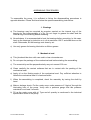
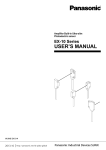
USER’S MANUAL
Heavy duty slurry pumps
TOYO PUMPS EUROPE
Edition 27.07.2007
SAFETY INSTRUCTIONS
TOYO PUMPS EUROPE
Edition 27.04.2007
User’s manual
for Toyo pumps
type «GR..-2 3~10HP»
This user’s manual will help you to
maintain your Toyo pump in optimum
working condition for a long time.
Please read carefully before using the
pump and keep for future reference.
Take note of the serial number which
you can find on the identification plate
of your pump.
The manufacturer reserves the right to
modify specifications and concept of these
products without previous notice.
Edition 27.04.2007
TOYO PUMPS EUROPE
Parc Industriel Sud – Zone II
Rue de l’Industrie, 41 – Belgium
Tel.: (32) 67.64.55.37
Fax. : (32) 67.64.55.31
E-mail: [email protected]
Web site: www.toyopumpseurope.com
TOYO PUMPS EUROPE
Edition 27.04.2007
CONTENTS
TOYO PUMPS EUROPE
Introduction
1
Precautions before operating
1
Notes on driving
2
Maintenance and troubleshooting
3
Points to be attentive
4
Troubleshooting list
5
Disassembling procedures
8
Assembling procedures
10
Technical specifications
12
Pump performance curve
13
Dimensions
14
Spare parts list
15
Exploded view drawings
18
Edition 27.04.2007
INTRODUCTION
A wrong utilisation and an inadequate manipulation of the pump will cause
unsatisfactory performances and early troubles. So, please read this instruction manual
carefully before operation.
PRECAUTIONS BEFORE OPERATING
1. Power supply
Check the power supply voltage and frequency by referring to the identification plate on
the pump.
Operation of the pump on a different power voltage from the specified voltage will cause
impossibility of pumping up and motor burning.
2. Grounding
Make sure to connect the pump correctly to the earth. The earth-cable is the green and
yellow coloured one.
3. Rotation direction
As to the rotating direction, counterclockwise rotation viewing from the suction intake
side (lower side of the pump) is the correct way of rotating. The rotation direction is
mentioned on the identification plate of the pump.
After connecting the pump, let it turn a short instant, out of the liquid to be pumped, in
order to check the motor direction by observing the agitator. Attention, the agitator can
detach itself when turning in opposite direction.
Should the electric motor turn in the wrong direction, you only need to invert two
alimentation wires.
Rotation in the air for a longer period of time causes damages to the seals.
The rotating direction of the agitator can be verified instantaneously.
Never drive the pump in opposite direction as it will cause early damages to the pump.
4. Protection of electric motor
It is, in any case, necessary to protect the pump with a correctly calibrated thermal
protection to avoid any overload and to install a start-stop switch. The supplier of the
pump can advise you the adequate material.
TOYO PUMPS EUROPE
-1-
Edition 27.04.2007
5. Cabtyre cable
a) The use of a cabtyre cable which has an inferior section or a superior length then
recommended can make the starting up of the pump impossible and provoke
damages to the motor.
Concerning the characteristics of the cable to use, please refer to the technical
characteristics of the pump.
b) Verify that the length of the alimentation cable corresponds to the depth at which the
pump has to work and this to avoid tearing out the cable.
c) In case of lengthening the cable fixed to the pump with a second cable, make sure
not to submerge the connection between the two cables.
6. Discharge hose
The diameter of the discharge hose fixed to the pump has to be adapted to the diameter
of the hose nipple of the pump. The discharge hose will at preference be fixed with halfcircular collars.
NOTES ON DRIVING
a) For your safety, never touch the agitator when the pump is connected, and never
pass underneath the pump while it is suspended.
b) If possible, avoid using the pump in conditions that provoke an overload.
See in particular to immerse the pump progressively until the material to pump is
reached.
c) Inspect the good working condition of the pump by verifying that the intensity of the
current does not pass the value indicated on the identification plate of the pump.
d) Avoid suspending the pump in such way that it gets buried at the bottom.
e) When the level of the pumped liquid is insufficient, it will cause noisy functioning and
generate an abnormal wear. In this case, add liquid or stop the pump and wait for
the liquid to rise.
f) Oversized materials, such as pieces of wood, etc. have, nevertheless the effect of
the agitator, propensity to present themselves at the entrance of the pump, which
has to be equipped with iron bars with holes of the same dimension as the holes of
the strainer. Consult your supplier.
g) The density of the pumped liquid can be verified by raising or descending the pump.
A to heavy density can provoke the blockage of the discharge hose and of the pump
and make pumping impossible. Heavy densities have to be avoided.
TOYO PUMPS EUROPE
-2-
Edition 27.04.2007
h) Use a sufficient resistant chain, which will be attached to the lifting handle provided
on the pump for transporting or handling the pump. The angle between the two parts
of the chain may not overshoot 60 degrees.
i) Never suspend the pump by its alimentation cable.
j) When the pump is in duty, it has to be immersed until the level indicated on the
schema representing the dimensions of the pump.
k) Rinse the pump and the discharge hose with clean water before turning it off.
MAINTENANCE AND TROUBLESHOOTING
a) Measure periodically the voltage of the alimentation current to verify that the pump
works at the correct voltage.
b) The electric resistance of the motor has to be verified at least once a month. If the
resistance of the motor is inferior to 100M Ohm, the winding of the electric motor has
to be dried and the tightness of the cables checked, etc.
c) The oil capacity in the under cover has to be verified every 500 hours. Therefore,
place the pump horizontally. If needed, add oil as specified in the table of technical
characteristics of the pump (normal or biodegrading) through the opening provided
to this end.
d) If the presence of water in the oil is established (whitish emulsion), or if the oil
contains solid particles (mud, etc.), it means that the seals are defective. Their
replacement is then required.
e) The quantity of oil in the under cover of the pump is specified in the technical
specifications of the pump.
f) If the flow of the pump is diminishing, the space between the impeller disc and the
impeller has to be checked. The recommended space is indicated in the technical
specifications of the pump.
TOYO PUMPS EUROPE
-3-
Edition 27.04.2007
POINTS TO BE ATTENTIVE
a) The maximum liquid temperature for the standard versions is 60°C.
b) Avoid that pumped materials (ex. mud,…) are sticked on the motor part of the pump.
This can provoke an abnormal heating of the motor. Clean the pump if this occurs.
c) If air occurs in the discharge hose, it happens that the liquid can not be pumped any
more. In that case, verify if the discharge hose is placed as horizontal as possible
(ex. avoid to large space between the floaters).
TOYO PUMPS EUROPE
-4-
Edition 27.04.2007
TROUBLESHOOTING LIST
The pump is in duty but doesn’t turn even as the switch is in “ON” position.
•
The pump emits no sound :
-
Electric alimentation problem:
à Verify if the network is under tension and/or the generator works properly.
-
Defective connection or breakdown of one of the alimentation wires:
à Verify all connections and check the state of the wires.
-
Alimentation throw one single phase :
à Verify the connections and fuses.
•
The pump emits a sound :
-
A foreign body blocs the agitator or is jammed between impeller and impeller disc :
à Remove the foreign body.
-
The impeller disc is blocked against the impeller :
à Adjust the space between the two parts as indicated in the technical
characteristics.
-
A bearing is broken :
à Replace the bearing.
-
Wire breakdown in one of the wires inside the winding of the stator :
à Consult your supplier.
-
The stator is burned :
à Consult your supplier.
TOYO PUMPS EUROPE
-5-
Edition 27.04.2007
The pump turns when the switch is in “ON” position but …
•
The pump emits an abnormal sound :
-
A foreign body blocs the agitator or is jammed between impeller and impeller disc :
à Remove the foreign body.
-
The impeller disc is in contact with the impeller :
à Adjust the space between the two parts as indicated in the technical
characteristics.
-
Defective bearing :
à Replace the bearing.
•
The flow of the pump is to weak :
-
The pump turns in the opposite direction :
à Inverse two of the three alimentation phases.
-
The level of the pumped liquid is insufficient :
à Add to the level.
-
Obstruction at the entrance of the pump or at the discharge hose :
à Verify and clean up.
-
Air in the discharge hose :
à Place the hose as horizontal as possible.
-
Wear of the impeller and the impeller disc :
à Adjust the space between the two parts as indicated in the technical
characteristics.
-
The pump provided to work in 60 Hz is furnished in 50 Hz :
à Consult your supplier.
-
Insufficient discharge pressure :
à Consult your supplier.
TOYO PUMPS EUROPE
-6-
Edition 27.04.2007
•
The thermal protection disconnects :
-
The density of the pumped liquid is to important :
à Lower the density by lifting the pump and/or by diluing the pumped
materials .
-
Important voltage drop :
à Replace the alimentation cable by a cable with correct section and length
as indicated in the technical specification of the pump..
-
The impeller disc is in contact with the impeller :
à Adjust the space between the two parts as indicated in the technical
characteristics.
-
One of the phases is missing :
à Complete inspection out of the liquid of the electric circuit going from the
source untill the electric motor.
-
The pump provided to work in 50 Hz is furnished in 60 Hz :
à Consult your supplier.
-
The electric motor is burned :
à Consult your supplier.
TOYO PUMPS EUROPE
-7-
Edition 27.04.2007
DISASSEMBLING PROCEDURES
Choose a dry and clean place to dismantle and reassemble your pump and install a
base on which you can put the pump. It is also wise to prepare a few small boxes in
which you can put the small parts dismantled from the pump. Prepare also some rags,
oil and tools.
The numbers mentioned between parenthesises in the description correspond to the
parts numbers in the spare parts list.
1. Disassembling of the electric cable
a) Unscrew the set bolts (34A) and remove the lead cover (7).
b) Dismantle the electric cable (1A) of the terminal board (52A). Remove the packing
(8).
c) In case you want to replace the electric cable, unscrew the set bolts (34A) and
remove the packing gland (3).Extract the cable from the lead cover (7) and detach
the cable protection tube A (2), the set ring (4) and the cable protection tube B (5).
2. Disassembling of the pump section
a) Place the pump horizontally and fix it in such way that it can not move during the
disassembling procedure.
b) Unscrew the cap nuts (47D) and remove the strainer (46).
c) The cutter fan (45) is screwed (normal right thread) on the shaft (17). To dismantle
the cutter fan, hit it with a mallet or hammer, by interposing a bronze or aluminium
jig, on one of the corners of the cutter fan. Unscrew it in counterclockwise direction,
the pump seen from beneath (aspiration side).
d) Unscrew the stay bolts (47A) and remove the suction cover (41). Remove the
packing(s) (42).
e) Unscrew the impeller nut (40) and the impeller collar (39). Remove the impeller (37),
the key (36).
f) Unscrew the set bolts (6A) and remove the vortex casing (38) with the collar (44).
g) Remove the distance collar (43).
TOYO PUMPS EUROPE
-8-
Edition 27.04.2007
3. Disassembling of the shaft sealed section
a) Unscrew one of the oil inlet bolts (48A) and its O-ring (48B) and collect the
lubrication oil in a recipient.
b) Unscrew the set bolt (34A) and remove the oil chamber cover (32). Remove the
packing (33).
c) Remove the shaft sleeve (30) from the shaft (17).
d) Extract the moving part of the mechanical seal (27A) from the shaft (17).
e) Unscrew the set bolts (26A) to extract the housing (28) and remove the packing (29).
f) Extract the fixed parts of the mechanical seal from the housing (28) and the oil
chamber cover (32).
g) Remove the oil seal (31) from the oil chamber cover (32).
h) Place the pump vertically upside down.
i) Unscrew the set bolts (34A) from the under cover (35) to extract the roller bearing
(23), shaft (17), rotor (15) and roller bearing (14) assembly.
j) Unscrew the set bolts (26A) from the bearing cover (25) to extract under cover (35).
Remove the packing (16).
k) If it is necessary, extract the roller bearings (14)(23).
4. Disassembling of the motor section
a) Return the pump and disconnect the six electric wires coming out of the motor from
the terminal board (52A) and from the thermal protection (13A).
b) Unscrew the set bolts (6A) and remove the upper cover (12) from the motor case
(20). Remove the packing (15).
c) Make sure not to hurt the electric wires coming out of the stator and the winding.
The disassembling of the pump is now finished. Take care to clean all parts before
reassembling them.
TOYO PUMPS EUROPE
-9-
Edition 27.04.2007
ASSEMBLING PROCEDURES
To reassemble the pump, it is sufficient to follow the disassembling procedures in
opposite direction. Please find here below the specific assembling instructions.
1. Bearings
a) The bearings may be mounted by pression exerted on the internal ring of the
bearing by the instrumentality of a jig. Do not forget to grease the shaft and the
internal ring of the bearing before mounting.
b) Nevertheless, it is recommended to heat the bearings before mounting. In this case,
heat up the bearings by induction or in oil at maximum 120°C and slide them on the
shaft. Afterwards, let the bearings cool down by air.
c) Use only grease for bearing lubrication or lithium grease.
2. Mechanical seal
a) This job should be done with care and in clean circumstances.
b) Do not open the package of the mechanical seal before starting the assembling.
c) The eccentricity and the perpendicularity may not exceed 0.03 mm.
d) Clean carefully the contact surfaces that are in contact with the packing of the
mechanical seal.
e) Apply oil on the floating seats of the mechanical seal. Pay sufficient attention to
handle the mechanical seal. It’s hard and brittle.
f) When the assembling is completed, check the assembly by turning the shaft by
hand.
g) Make a leakage check. Put the under cover under pressure of 3 kg/cm² through the
lubricating hole of the pump. Verify with a pressure gauge that this pressure
maintains for at least 3 minutes.
h) Fill up the under cover with oil. Type and oil quantity is mentioned in the technical
specification sheet of the pump.
TOYO PUMPS EUROPE
- 10 -
Edition 27.04.2007
3. Other seals
Renew all seals after disassembling.
4. Electric connection
Connect the pump as shown on the drawing here below.
Alimentation 3 x 400 V
R
S
T
Z
X
Thermal
protection
Terminal board
U
V
W
Y
Motor
Not forget to remake the full one with the oil bath by the opening envisaged for this
purpose. Type and quantity of oil are specified in the technical features of the pump.
TOYO PUMPS EUROPE
- 11 -
Edition 27.04.2007