1
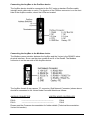
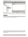
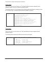
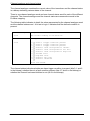
User Manual Profibus DP Master to Crowcon Vortex Gas Analyser Formac Electronics Ltd., 16-17 Brassmill Enterprise Centre, Brassmill Lane, Bath, BA1 3JN 1/16 Formac Electronics Ltd. T:+44 (0) 1225 338176 F:+44 (0) 1225 446094 e: [email protected] W:www.formac.net User Manual - ProfiBus to Vortex Interface 13/06/2006 Rev.1.1 Document Revison History Revision & date 1.0 (2006-06-12) 1.1 (2006-06-13) 1.2 (2008-07-10) Detail of changes Created. Errors and additions Refreshed external links 2/16 Formac Electronics Ltd. Author OG OG MW User Manual - ProfiBus to Vortex Interface 10/07/2008 Authorised JM JM Rev.1.2 Overview............................................................................................................................. 4 Requirements..................................................................................................................... 5 HMS equipment: .............................................................................................................. 5 Crowcon equipment: ........................................................................................................ 5 Configuration Layout ........................................................................................................ 6 AnyBus Layout ................................................................................................................. 6 Hardware Settings ............................................................................................................. 7 AnyBus Module ................................................................................................................ 7 Profibus address ........................................................................................................................................7 Modbus address ........................................................................................................................................7 Connecting the AnyBus to the Profibus device ................................................................ 8 Connecting the AnyBus to the Modbus device ................................................................. 8 Hardware Configuration .................................................................................................... 9 Profibus Configuration...................................................................................................... 9 Profibus AnyBus Configuration ..................................................................................................................9 Modbus Configuration ...................................................................................................... 9 Software Configuration ................................................................................................... 10 AnyBus Software Configuration ..................................................................................... 10 Overview ..................................................................................................................................................10 ABC Config Tool ......................................................................................................................................10 Profibus Configuration .............................................................................................................................10 Modbus Configuration ..............................................................................................................................10 AnyBus Mapping ......................................................................................................................................11 System Status ..........................................................................................................................................14 Power Status............................................................................................................................................14 Channel analogue and channel status ....................................................................................................15 Technical documentation ............................................................................................... 16 Crowcon Vortex Unit ...................................................................................................... 16 Vortex Configuration ................................................................................................................................16 HMS AnyBus Profibus-DP Serial Gateway .................................................................... 16 GSD-File ..................................................................................................................................................16 Installation Leaflet ....................................................................................................................................16 3/16 Formac Electronics Ltd. User Manual - ProfiBus to Vortex Interface 10/07/2008 Rev.1.2 Overview This document defines an interface between a Profibus master (PLC) and a Crowcon Vortex gas analyser. The Profibus master communicates with the Vortex (Modbus slave) using the HMS AnyBus Profibus-DP Serial Gateway device. The Anybus module acts as a protocol bridge between the Profibus master and the Vortex Modbus slave. 4/16 Formac Electronics Ltd. User Manual - ProfiBus to Vortex Interface 10/07/2008 Rev.1.2 Requirements HMS equipment: 1 x Profibus slave module (AnyBus Profibus-DP Serial Gateway) 1 x GSD file for the AnyBus module (HMS_1803.GSD). This file can be downloaded from the following web page: http://www.anybus.com/support/support.asp?PID=104&ProductType=Anybus%20Communicator Crowcon equipment: 1 x Vortex Manual 1 x Crowcon Resource CD – Vortex PC 1 Vortex gas analyser with the following hardware configuration: 1x 3x 12 x 4x 1x 1x Node Control Module Quad Channel Module Ammonia sensor 0 – 1000 p.p.m. Relay Module Power Monitoring Module 220 VOLTS AC converter 5/16 Formac Electronics Ltd. User Manual - ProfiBus to Vortex Interface 10/07/2008 Rev.1.2 Configuration Layout The following picture shows how to attach the different components of the system. AnyBus Layout The HMS AnyBus device is connected to the Vortex Node Control Module using the AnyBus RS485 connector (located at the bottom of the unit). The next section explains exactly which PINs should be connected from the HMS AnyBus device to the Crowcon Vortex unit. 6/16 Formac Electronics Ltd. User Manual - ProfiBus to Vortex Interface 10/07/2008 Rev.1.2 Hardware Settings AnyBus Module The AnyBus module acts as a protocol converter Profibus/Modbus and vice-versa. This device has been configured as a Profibus slave and as a Modbus Master. Profibus address In order to change the Profibus slave address open the AnyBus front case (Profibus side) and set the address using the two rotary switches accordingly. For example, to set the AnyBus device as a Profibus slave address number 3, the x 10 rotary switch must be set to zero and the x 1 rotary switch must be set to 3. Please consult the HMS documentation for further details (Technical documentation: HMS AnyBus-DP Serial Profibus Gateway section). Please note the initial Profibus address has been set to 77 Modbus address The Modbus address that the AnyBus queries is Modbus address 1, so the Vortex unit has to be configured as slave address number 1. 7/16 Formac Electronics Ltd. User Manual - ProfiBus to Vortex Interface 10/07/2008 Rev.1.2 Connecting the AnyBus to the Profibus device The AnyBus device should be connected to the PLC using a standard Profibus cable (straight serial cable male to male). The location of the Profibus connector is on the front side of the AnyBus module, where the LEDs are located: Connecting the AnyBus to the Modbus device The Modbus communication between the AnyBus and the Vortex is the RS485 2-wires physical interface. So we use the pins number 8 and 9 of the Dsub9. The Modbus connector is on the rear side of the AnyBus device. The AnyBus female 9 way cannon “D” connector (Sub Network Connector) shown above should be connected to the Vortex Node Controller Module as follows: ANYBUS CONNECTOR PIN 8 PIN 9 VORTEX NODE CONTROLLER --------------------------------------------------------------------------------------------------------- PIN 4 PIN 5 Please read the Crowcon documentation for further details (Technical documentation: Vortex Unit section). 8/16 Formac Electronics Ltd. User Manual - ProfiBus to Vortex Interface 10/07/2008 Rev.1.2 Hardware Configuration Profibus Configuration In order to configure the AnyBus Profibus protocol, the PLC must be configured to use the ProfiBus communication (the AnyBus device as a Profibus slave). Please refer to the PLC documentation in order to install and configure this device (Technical Documentation). Profibus AnyBus Configuration Importing the GSD file Import the file HMS_1803.GSD to the PLC software (PLC configurator tool) in order to include the AnyBus as a Profibus slave in the Profibus network. Configuring the network The AnyBus module can be found in the hardware PLC catalogue. Please consult the HMS documentation for further details in order to connect the AnyBus device to a PLC Profibus bus (Technical documentation: AnyBus installation for PLC). Modbus Configuration The Modbus units have to be configured as a slave address number 1 in order to be accessed properly by the AnyBus communicator. Please consult the Crowcon documentation (Technical documentation: Vortex Unit section). 9/16 Formac Electronics Ltd. User Manual - ProfiBus to Vortex Interface 10/07/2008 Rev.1.2 Software Configuration AnyBus Software Configuration Overview Basically, the AnyBus device is a bridge between the Profibus protocol and the Modbus protocol. The AnyBus has got three memory buffers: Input data: data that should be sent to the Profibus device (i.e. PLC). Output data: data received from the Profibus device. General data: data to perform internal calculations. In this particular project, just only the first buffer is interesting. The PLC will read data from the Vortex unit but it not necessary to send anything from the PLC to the Vortex. ABC Config Tool The ABC Config tool is the HMS software that allows sending Modbus commands and mapping the response in the input data buffer. This software can be downloaded from the following location: http://www.anybus.com/upload/AnyBus%20Communicator-8255-ABC_Setup_2_10.exe Once the software has been installed, it is possible to communicate to the AnyBus device using the programming cable. Two things have to be configured: the Profibus protocol and the Modbus Protocol. Profibus Configuration The AnyBus device will be automatically detected once the PLC software has imported the GSD file. Obviously, the AnyBus configuration switches for setting the Profibus address have to be set previously (see the Hardware Configuration section in this document). Modbus Configuration Using the ABC Config Tool it is possible to send standard Modbus commands or to specify new ones. For clarity, this document describes only the Read Holding Registers. To send a Modbus command is as easy as create new Read Holding Register object, which consist of a fully configurable Modbus query and a response. The following picture shows a Read Holding Register object into the ABC Config Tool. The picture highlights the starting address of the Modbus packet, which is 0x0BB7. 10/16 Formac Electronics Ltd. User Manual - ProfiBus to Vortex Interface 10/07/2008 Rev.1.2 To change any other value, select the appropriate field and change the value accordingly. AnyBus Mapping The last thing to do is to map the Modbus data into the AnyBus input buffer in order to be consumed by the Profibus device. The Response Data property allows indicating where to map the value/values read from the Modbus response. The following picture shows the values associated with the Data property. In this example, the Modbus payload has 0x0068 bytes and will be mapped in the input buffer starting at 0x007C address. So 0x0068 bytes will be available to be consumed by the PLC via the Profibus interface. 11/16 Formac Electronics Ltd. User Manual - ProfiBus to Vortex Interface 10/07/2008 Rev.1.2 The application downloaded into the AnyBus can be modified importing the source code called „Vortex_Final.cfg‟ via the File Open menu. PLC Configuration The AnyBus device sends 228 bytes from the Modbus device (Vortex) to the Profibus bus. Only a subset of this data is interesting for the project. The following table shows the starting address and description of the Profibus set of data that the PLC must read: 12/16 Formac Electronics Ltd. User Manual - ProfiBus to Vortex Interface 10/07/2008 Rev.1.2 PROFIBUS MAPPING WORD BYTE 0 1 2 3 4 5 6 7 8 9 10 11 12 13 14 15 16 17 18 19 20 21 22 23 ... ... 32 33 ... ... 42 43 ... ... 52 53 ... ... 62 63 ... ... 72 73 ... ... 82 83 ... ... 92 93 ... ... 102 103 ... ... 112 113 INFORMATION 0 SYSTEM STATUS 2 POWER STATUS 4 CHANNEL 1 ANALOGUE 6 CHANNEL 1 STATUS 8 XXX 10 XXX 12 XXX 14 XXX 16 XXX 18 XXX 20 XXX 22 XXX 24 CHANNEL 2 ANALOGUE 26 CHANNEL 2 STATUS 28 XXX 30 XXX 32 XXX 34 XXX 36 XXX 38 XXX 40 XXX 42 XXX 44 CHANNEL 3 ANALOGUE 46 CHANNEL 3 STATUS ... 64 CHANNEL 4 ANALOGUE 66 CHANNEL 4 STATUS ... 84 CHANNEL 5 ANALOGUE 86 CHANNEL 5 STATUS ... 104 CHANNEL 6 ANALOGUE 106 CHANNEL 6 STATUS ... 124 CHANNEL 7 ANALOGUE 126 CHANNEL 7 STATUS ... 144 CHANNEL 8 ANALOGUE 146 CHANNEL 8 STATUS ... 164 CHANNEL 9 ANALOGUE 166 CHANNEL 9 STATUS ... 184 CHANNEL 10 ANALOGUE 186 CHANNEL 10 STATUS ... 204 CHANNEL 11 ANALOGUE 206 CHANNEL 11 STATUS ... 224 CHANNEL 12 ANALOGUE 226 CHANNEL 12 STATUS 13/16 Formac Electronics Ltd. User Manual - ProfiBus to Vortex Interface 10/07/2008 Rev.1.2 The structure of each of the words is as follows: System Status This occurs once for each Vortex unit. The System Status has been mapped at word address number 0 as you can see in the previous table. The system status is a 16-bit bitmap and the following table identifies the meaning of each bit. A bit set to logic 1 indicates that the defined condition is present. System status 1 word Bitmap, where the bits are defined as follows: 0 1 2 3 4 5 6 7 8 9 Channel Test Mode active Jump/Hold Mode active System fault System fault is Battery fault System fault is FRAM Data Integrity fault System fault is Internal I2C Bus fault System fault is Display Access fault System fault is Power Monitor Access fault System fault is External I2C Bus fault System fault is Relay Board fault 10-15 are unused. Power Status This occurs once for each Vortex Unit. The Power Status has been mapped at word address number 1. The following table explains the different values that can be read: Power status 1 word 14/16 Formac Electronics Ltd. Integer, where the values are defined as follows: 0 1 2 3 4 5 OK Mains OK Battery LOW Mains FAIL Battery GOOD Mains OK Battery DISCONNECTED Mains FAIL Battery LOW No communications to Power Card User Manual - ProfiBus to Vortex Interface 10/07/2008 Rev.1.2 Channel analogue and channel status The channel analogue contains the current value of the transducer and the channel status is a bitmap indicating various states of the channel. There is one channel analogue word and one channel status word for each of the different channels. The channel analogue and the channel status are consecutive words in the Profibus mapping. The following table indicates in detail the value represented by the channel analogue word and the channel status word. A bit set to logic 1 indicates that the defined condition is present. Channel analogue Integer between 0 and 1000. 1 word The current reading on the detector. Channel status Bitmap, where the bits are defined as follows: 1 word 0 1 2 3 4 5 6 7 8 9 Alarm 1 trigger condition present Alarm 2 trigger condition present Alarm 3 trigger condition present Detector level interpreted as inhibit Detector level interpreted as Low Info Detector level interpreted as High Info Low End fault High End fault Detector I2C fault Detector inhibited 10-15 are unused. The channel status indicates whether an alarm trigger condition is present (bits 0, 1 and 2 in the bitmap), whether there is a fault condition present (bits 6,7 and 8 in the bitmap) or whether the channel has been inhibited or not (bit 9 in the bitmap). 15/16 Formac Electronics Ltd. User Manual - ProfiBus to Vortex Interface 10/07/2008 Rev.1.2 Technical documentation In order to know in more detail how to configure the different modules of this project please refer to the following documentation: Crowcon Vortex Unit Vortex Configuration Vortex 12 Channel Gas and Fire Control Panel, Crowcon Detection instruments Ltd. This document is already included with the hardware. HMS AnyBus Profibus-DP Serial Gateway GSD-File GSD-File for AnyBus Profibus Serial Gateway, HMS Industrial networks This file can be downloaded from the following web page: http://www.anybus.com/support/support.asp?PID=104&ProductType=AnyBus%20Communicator Installation Leaflet Installation Guide, HMS Industrial Networks This leaflet can be downloaded from the following web page: http://www.anybus.com/support/support.asp?PID=104&ProductType=AnyBus%20Communicator 16/16 Formac Electronics Ltd. User Manual - ProfiBus to Vortex Interface 10/07/2008 Rev.1.2