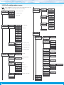
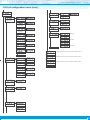
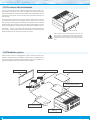
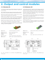
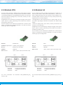
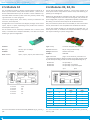
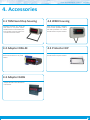
1
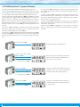
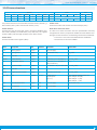
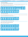
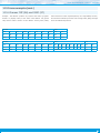
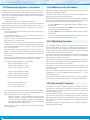
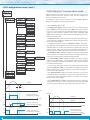
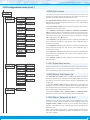
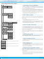
User’s Manual
ELECTRONICS
FOR
INDUSTRIAL
AUTOMATION
PANEL METERS . SIGNAL CONVERTERS . LARGE DISPLAYS
Series K . K40-485
Display for serial protocol RS-485 ASCII
PANEL meters
Display for ASCII protocol with RS-485 communications bus, with 4 digits and 20 mm digit height,
in red color. Reading range from 9999 to -1999 with decimal point. Local or remote alarm control.
‘Watchdog’ function and ‘bus activity’ function. Standard 96 x 48 mm size (1/8 DIN). Fast access to
‘bus ativity’, alarm setpoints and memory of max and min. ‘On power up’ function, configurable reading brightness, password. Universal AC and DC power. Up to 3 optional modules for output and control (relays, analog outputs, Modbus RTU communications, RS-485 ASCII, RS-232, ...)
www.fema.es
3802r01
Tel. (+34) 93.729.6004 [email protected]
FEMA ELECTRÓNICA . Series K . K40-485
1. Panel meter K40-485
Display for ASCII protocol with RS-485 bus, in 96 x 48 mm (1/8 DIN) format
Digital panel meter, with ASCII code repeater function, in 96 x 48 mm
size (1/8 DIN) and 4 digits with 20 mm digit height. Reading value,
together with decimal point, are controlled via the RS-485 bus, using the ASCII protocol described in this document (see section 1.13).
Reading up to 9999 and -1999.
Three working modes available allow to work with numbers or alphanumerical symbols. Alarms can be controlled directly from the
RS-485 bus or locally from the instrument.
• The ‘Process slave’ (see section 1.2) mode works with numerical
values, and alarms are controlled locally.
• The ‘Full slave’ (see section 1.3) mode works with numerical values, and alarms are controlled from the bus.
• The ‘Text’ (see section 1.4) mode works with alphanumerical values, and alarms are controlled from the bus.
Bus speed configurable up to 38.400 bps and address configurable
from 1 to 31. Accepts a ‘broadcast’ function at address 128. ‘Watchdog’ function detects if communication with the master is lost.
‘Watchdog’ function can display a message on display and control
the activation of selected alarms (see section 1.25).
Function ‘bus activity’ is a utility for troubleshooting communications (see section 1.26). Function ‘On power up’ defines the alarm
state at start-up (see section 1.28.8).
Front protection IP54 with optional IP65. Connections by plug-in
screw terminals. For industrial applications.
• ‘Fast access’ menu to selected functions, accessible with key UP (5)
(see section 1.28.6)
Memory for maximum and minimum reading, password protection,
5 brightness levels.
Index
1. Panel meter K40-485 . . . . . . . . . . . . . . . . . . . . . . 2
1.1 How to order . . . . . . . . . . . . . . . . . . . . . . . . . 3
1.2 ‘Process slave’ mode . . . . . . . . . . . . . . . . . . . . 3
1.3 ‘Full slave’ mode . . . . . . . . . . . . . . . . . . . . . . . 3
1.4 ‘Text’ mode . . . . . . . . . . . . . . . . . . . . . . . . . 3
1.5 Typical application . . . . . . . . . . . . . . . . . . . . . . 3
1.6 Front view . . . . . . . . . . . . . . . . . . . . . . . . . . 4
1.7 Power connections . . . . . . . . . . . . . . . . . . . . . 4
1.8 Start up sequence . . . . . . . . . . . . . . . . . . . . . . 4
1.9 Rear view . . . . . . . . . . . . . . . . . . . . . . . . . . . 4
1.10 Signal connections . . . . . . . . . . . . . . . . . . . . . 4
1.11 Technical specifications . . . . . . . . . . . . . . . . . . 5
1.12 Mechanical dimensions (mm) . . . . . . . . . . . . . . 5
1.13 ASCII protocol - Types of frames . . . . . . . . . . . . . 6
1.14 Frame structure . . . . . . . . . . . . . . . . . . . . . . 7
1.15 Frame examples . . . . . . . . . . . . . . . . . . . . . . 8
1.15.1 Frames ‘WRA’ (35) and ‘OK’ (39) . . . . . . . . . . . 8
1.15.2 Frame ‘ERR’ (38) . . . . . . . . . . . . . . . . . . . . 8
1.15.3 Frames ‘PING’ (32) and ‘PONG’ (33) . . . . . . . . . 8
1.15.4 Frames ‘RD’ (36) and ‘ANS’ (37) . . . . . . . . . . . . 9
1.16 Registers in ‘Process slave’ mode . . . . . . . . . . . . 10
1.17 Registers in ‘Full slave’ mode . . . . . . . . . . . . . . 10
1.18 Registers in ‘Text’ mode . . . . . . . . . . . . . . . . . 11
1.19 CRC calculation . . . . . . . . . . . . . . . . . . . . . . 11
1.20 The ‘Alarm status’ register . . . . . . . . . . . . . . . . 12
1.21 Representable characters . . . . . . . . . . . . . . . . 12
1.22 Messages and errors . . . . . . . . . . . . . . . . . . . 13
1.23 Numerical registers : restrictions . . . . . . . . . . . . 14
1.24 Addresses and ‘broadcast’ . . . . . . . . . . . . . . . 14
1.25 ‘Watchdog’ function . . . . . . . . . . . . . . . . . . . 14
1.26 ‘Bus activity’ function . . . . . . . . . . . . . . . . . . 14
1.27 How to operate the menus . . . . . . . . . . . . . . . 15
1.28 Configuration menu . . . . . . . . . . . . . . . . . . . 16
1.28.1 Initial set-up . . . . . . . . . . . . . . . . . . . . . 16
1.28.2 Bus configuration . . . . . . . . . . . . . . . . . . . 16
1.28.3 Configuration . . . . . . . . . . . . . . . . . . . . . 17
1.28.4 Alarms in ‘Full slave’ and ‘Text’ mode . . . . . . . 17
1.28.5 Alarms in ‘Process slave’ mode . . . . . . . . . . . 18
2
1.28.6 Fast access . . . . . . . . . . . . . . . . . . . . . . 19
1.28.7 Super fast access . . . . . . . . . . . . . . . . . . . 19
1.28.8 Menu ‘On Power Up’ . . . . . . . . . . . . . . . . . 19
1.28.9 Menu ‘Setpoint on bus’ . . . . . . . . . . . . . . . 19
1.28.10 Menu ‘Save to E2PROM’ . . . . . . . . . . . . . . 20
1.28.11 Menu ‘Key LE’ . . . . . . . . . . . . . . . . . . . . 20
1.28.12 Function ‘Password’ . . . . . . . . . . . . . . . . 20
1.28.13 Factory reset . . . . . . . . . . . . . . . . . . . . 20
1.28.14 Firmware version . . . . . . . . . . . . . . . . . . 20
1.28.15 Brightness . . . . . . . . . . . . . . . . . . . . . . 20
1.28.16 Access to optional modules . . . . . . . . . . . . 20
1.29 Factory configuration . . . . . . . . . . . . . . . . . . 21
1.30 Full configuration menu . . . . . . . . . . . . . . . . . 22
1.31 To access the instrument . . . . . . . . . . . . . . . . 24
1.32 Modular system . . . . . . . . . . . . . . . . . . . . . 24
1.33 Precautions on installation . . . . . . . . . . . . . . . 25
1.34 Warranty . . . . . . . . . . . . . . . . . . . . . . . . . 25
1.35 CE declaration of conformity . . . . . . . . . . . . . . 25
2. Output and control modules . . . . . . . . . . . . . . . . . 26
2.1 Module R1 . . . . . . . . . . . . . . . . . . . . . . . . . 26
2.2 Module AO . . . . . . . . . . . . . . . . . . . . . . . . . 26
2.3 Module RTU . . . . . . . . . . . . . . . . . . . . . . . . 27
2.4 Module S4 . . . . . . . . . . . . . . . . . . . . . . . . . 27
2.5 Module S2 . . . . . . . . . . . . . . . . . . . . . . . . . 28
2.6 Modules R2, R4, R6 . . . . . . . . . . . . . . . . . . . . 28
3. Other options . . . . . . . . . . . . . . . . . . . . . . . . . 30
3.1 Option NBT . . . . . . . . . . . . . . . . . . . . . . . . . 30
3.2 Option 65 . . . . . . . . . . . . . . . . . . . . . . . . . 30
4. Accessories . . . . . . . . . . . . . . . . . . . . . . . . . . 31
4.1 THM benchtop housing . . . . . . . . . . . . . . . . . . 31
4.2 Adapter DRA-M . . . . . . . . . . . . . . . . . . . . . . 31
4.3 Adapter KA96 . . . . . . . . . . . . . . . . . . . . . . . 31
4.4 WME housing . . . . . . . . . . . . . . . . . . . . . . . 31
4.5 Protector KIP . . . . . . . . . . . . . . . . . . . . . . . . 31
FEMA ELECTRÓNICA . Series K . K40-485
1.1 How to order
Model
K40
485
-
Power
-
H
-H
-L
Option 1
-
-
(85-265 Vac/dc)
(11/60 Vdc,
24 Vac, 48 Vac)
Option 2
-R1
-AO
-RTU
-S4
-S2
-
Option 3
-
Others
-NBT
-65
(1 relay)
(analog output)
(Modbus RTU)
(RS-485)
(RS-232)
(empty)
(no buttons)
(front IP65)
1.2 ‘Process slave’ mode
1.4 ‘Text’ mode
In ‘Process slave’ mode, the instrument receives a numerical value
though the RS-485 bus. Alarms and analog outputs are locally controlled by the instrument according to the alarm configuration and
display value.
• Alarms - alarm setpoint is manually configured through the
front keypad. Alarm activates or deactivates according to the
setpoint value configured and the display value. Relay outputs
are associated to alarms. To enable access to setpoint registers
through the communications bus, enable the ‘Setpoint on bus’
function (see section 1.28.9).
• Analog outputs - analog outputs are manually configured
through the front keypad. Analog output value is associated to
the display value.
In ‘Text’ mode the instrument receives a set of ASCII characters
through the RS-485 bus. Characters are not treated as a numerical
value, but as a set of individual ASCII characters. Available characters
are described in section 1.21. Alarm status are controlled through
the RS-485 bus
• Alarms - alarm status (‘on’ / ‘off’) is controlled by writing on the
alarm status register (see section 1.20).
• Analog outputs - analog output are not available in this mode.
RS-485 ASCII
Alarms
Reading
RS-485 ASCII
K40-485 display in ‘Text’ mode
Alarms
Display
Analog outputs
K40-485 display in ‘Process slave’ mode
1.3 ‘Full slave’ mode
In ‘Full slave’ mode, display value and alarm status are controlled
through the RS-485 bus.
• Alarms - alarm status (‘on’ / ‘off’) is controlled by writing on the
alarm status register (see section 1.20).
• Analog outputs - analog output are manually configured
through the front keypad. Analog output signal is associated to
the display value.
1.5 Typical application
Display of numerical values associated to the production or industrial
processes. Display value is controlled through the RS-485 bus using
ASCII protocol. Messages are sent by the bus master, usually a PLC
or a SCADA system. Relay status can be controlled directly from the
PLC or locally from the instrument, depending on the configuration
of the instrument.
RS-485 ASCII
RS-485 ASCII
Alarms
4/20mA
(isolated)
Relay 1
Analog outputs
Relay 2
Display
K40-485 display in ‘Full slave’ mode
3
FEMA ELECTRÓNICA . Series K . K40-485
1.6 Front view
1.9 Rear view
Option 3
Alarms
Logo
Button ‘LE’
Units
Units
Button ‘UP’
Button ‘SQ’
‘Fast access‘
‘Configuration menu’
Option 1
1 2 3
Option 2
8 9 0
Signal
(see section 1.10)
Power
(see section 1.7)
(see section 1.28.6) (see section 1.28)
Detail of the plug-in screw terminals provided with
the instrument. The instrument is provided with all
terminals needed, both male and female.
1.7 Power connections
Earth connection - Although a
terminal is provided for earth
connection, this connection is
optional. The instrument does
not need earth connection for
correct operation nor for compliance with the security regulations.
8 9 0
1.10 Signal connections
~
+
~
-
Fuse - To comply with security regulation 61010-1, add to the power
line a protection fuse acting as disconnection element, easily accessible to the operator and identified as a protection device.
Power ‘H’ fuse 250 mA time lag
Power ‘L’
fuse 400 mA time lag
1 2 3
B
A
GND
1.8 Start up sequence
The instrument follows the sequence indicated below at start-up after a power loss :
1. alarm status according to configuration (see section 1.28.8)
2. start up delay according to configuration (see section 1.28.8)
3. all registers initialized to value ‘0’
3.1 display set to ‘0’
4. detection of the active working mode ‘Full slave’ or ‘Process
slave’ or ‘Text’
4.1 in ‘Full slave’ mode (see section 1.3) and ‘Text’ mode (see
section 1.4) the alarm state is set as explained in ‘1.’ and alarm
registers are set to ‘0’
4.2 in ‘Process slave’ mode (see section 1.2) alarm configuration (setpoint, etc) is compared with display value (‘0’) and
each alarm activates or deactivates according to the result of
the comparison
5. waits for data reception through the communications bus
4
FEMA ELECTRÓNICA . Series K . K40-485
1.11 Technical specifications
ProtocolASCII
BusRS-485
Speed
from 38.400 bps to 600 bps
(19.200 bps by default)
Data format
8n1, 8e1, 8o1, 8n2
Address
1 to 31
Bus terminators
not included
Digits
number of digits
4
led 7 segments led
colorred
digit height
20 mm
Reading
maximum reading
minimum reading
decimal point
Watchdog
Errors
9999
-1999
X.X.X.X
Section
Fast access
yes, configurable
1.28.6
Watchdog
yes, configurable
1.25
Scroll
in ‘Text’ mode
Remote or local alarms
configurable
1.28.4 y
1.28.5
‘watchdog’ alarms
configurable
1.25
‘On Power Up’
yes
1.28.8
Function ‘Bus activity’
yes
1.26
Function ‘Setpoint on bus’
yes, in ‘Process slave’
mode
1.28.9
Memory
maximum, minimum
1.28.6
Password
configuration block
1.28.12
Alarms in local mode
setpoint
double setpoint
activation delay
deactivation delay
hysteresis
inverted relay
deactivation lock
1.28.5
Display brightness
5 levels
1.28.15
configurable from 1 to 120 seconds
if communication with the ‘master’ is
lost
Power
power ‘H’
power ‘L’
isolation*
consumption
85 to 265 Vac/dc
11 to 60 Vdc and 24/48 Vac
2500 Veff with power ‘H’
1500 Veff with power ‘L’
*tested for 60 sec.
<1.5 W only meter
<4.0 W meter with options
Configuration
3 buttons front keypad
Front protection
IP54 standard
IP65 optional (see section 3.2)
Output and control options relays, analog outputs, serial communications (see section 2)
Mechanical
mounting panel
connections
plug-in screw terminal
housing material ABS, polycarbonate (V0)
weight <150 grams
front size
96 x 48 mm (1/8 DIN)
panel cut-out
92 x 44 mm
depth from panel 91 mm (including terminals)
Temperature
operation storage warm-up time
Functions included
from 0 to +50 ºC
from -20 to +70 ºC
15 minutes
1.28.3
Table 1 - Functions included
1.12 Mechanical dimensions (mm)
48
96
16
44
75
8
Panel
cut-out
92
5
FEMA ELECTRÓNICA . Series K . K40-485
1.13 ASCII protocol - Types of frames
The ASCII protocol used defines the following types of frames :
• Frame ‘write’ (‘WR’). Identifier 34. Frame to write data into a register. The register number is indicated in the ‘REG’ byte (section ‘Header’). Bytes ‘D0’ to ‘Dn’ (section ‘Data’) contain the data to write.
• Frame ‘write with acknowledgment’ (‘WRA’). Identifier 35. Frame
to write data into a register, with acknowledgment of success. The
register number is indicated in the ‘REG’ byte (section ‘Header’).
Bytes ‘D0’ to ‘Dn’ (section ‘Data’) contain the data to write. The instrument will reply with a ‘ok’ frame (‘OK’) if the writing action succeeded, or with a ‘error’ frame (‘ERR’) if the writing action did not
succeed.
• Frame ‘ok’ (‘OK’). Identifier 39. Informs that the action of writing
data into a register, was successful. This is a response frame to a
‘write with acknowledgment’ frame (‘WRA’).
• Frame ‘error’ (‘ERR’). Identifier 38. Informs that the data read (‘RD’)
or data write (‘WRA’) did not succeed. The error code is codified into
the ‘REG’ byte (section ‘Header’). For a list of error codes see section
1.22.
• Frame ‘read’ (‘RD’). Identifier 36. Frame to request the data value
of a register. The register number is indicated in the ‘REG’ byte (section ‘Header’).
• Frame ‘answer’ (‘ANS’). Identifier 37. Response frame containing
the requested data of a ‘read’ frame. The register number is indicated inthe ‘REG’ byte (section ‘Header’). Bytes ‘D0’ to ‘Dn’ (section
‘Data’) contain the requested data.
• Frame ‘ping’ (‘PING’). Identifier 32. Frame ‘ping’ is a request of
existence to the remote instrument. The remote instrument will answer with a ‘pong’ frame.
• Frame ‘pong’ (‘PONG’). Identifier 33. Frame ‘pong’ is a response
frame to a ‘ping’ frame. It confirms the existence of the remote instrument.
• Frame ‘write’ (‘WR’)
Example, write of the display value.
Units
• Frame ‘write with acknowledgment’ (‘WRA’)
• Frame ‘ok’ (‘OK’) ...
• ... or frame ‘error’ (‘ERR’)
Example, write of the display value with
request of confirmation. Confirmation is a
‘ok’ frame or a ‘error’ frame.
Units
• Frame ‘read’ (‘RD’)
• Frame ‘answer’ (‘ANS’) ...
• ... or frame ‘error’ (‘ERR’)
Example, reading of the display value and
response from the remote instrument
with the value of the display register.
Units
• Frame ‘ping’ (‘PING’)
Example, confirmation that the remote instrument exists and is operative. Answer is
a ‘pong’ frame.
• Frame ‘pong’ (‘PONG’)
Units
6
FEMA ELECTRÓNICA . Series K . K40-485
1.14 Frame structure
Header
Data
STX
ID
RSV
FROM
TO
REG
RSV
LONG
2
x
32
x
x
x
32
n+1
0
1
2
3
4
5
6
7
D0
D1
8
9
Trail
...
Dn
CRC
x
3
...
n+7
n+8
n+9
[data]
ETX
The protocol frames are structure with a header section (‘Header’), a
data section (‘Data’) and a end of frame section (‘Trail’).
Section ‘Trail’
Contains the ‘CRC’ code and the end of frame byte (‘ETX’).
Section ‘Header’
Contains the start of frame byte (‘STX’), the frame identifier (‘ID’),
the sender (‘FROM’) and destination (‘TO’) addresses, the register
number (‘REG’) and the length (‘LONG’) of the ‘Data’ section.
‘Real value’ and ‘Frame value’
In order to use frame characters that are representable and easily
recognizable on screen, the protocol codifies the values before introducing them into the frame. The following nomenclature is defined :
• ‘real value’ is the value of the field without codification
• ‘frame value’ is the value codified
Section ‘Data’
Contains the data of the register (‘REG’).
Field
Description
Size
Position
Real value
Frame value
STX
Start of frame
1 byte
0
does not apply
2
ID
Type of frame
1 byte
1
(see section 1.13)
real_value
RSV
Reserved
1 byte
2
0
32
FROM
Sender address
1 byte
3
0 (‘Master’) / 1 a 31 (‘Slave’)
32 + real_value
TO
Destination address
1 byte
4
0 (‘Master’) / 1 a 31 (‘Slave’)
128 (‘broadcast’)
32 + v
REG
Register number
1 byte
5
see sections 1.16, 1.17 and 1.18 32 + real_value
RSV
Reserved
1 byte
6
0
32
LONG
Length of ‘Data’ section
1 byte
7
n (between 0 and 32)
32 + real_value
D0 … Dn
Data
n bytes
8 a n+7
number 0 to 9
decimal point
sign (+/-)
ASCII code for number (48 to 57)
ASCII code for dot (46)
ASCII code for ‘+’ (43)
ASCII code for ‘-’ (45)
CRC
CRC calculated value
1 byte
n+8
does not apply
(see section 1.19)
ETX
End of frame
1 byte
n+9
does not apply
3
Table 2 - Description of the ASCII frame bytes
7
FEMA ELECTRÓNICA . Series K . K40-485
1.15 Frame examples
1.15.1 Frames ‘WRA’ (35) and ‘OK’ (39)
Example - The ‘Master’ (address ‘0’) sends a write frame, with request of acknowledgment, (frame ‘WRA’) with value ‘65.43’ to register number ‘0’ (display value) to the ‘Slave’ with address ‘28’. The
‘Slave’ answers to the ‘Master’ with a ‘ok’ frame (‘OK’). In case of
error, it will answer with a ‘error’ frame (‘ERR’).
Header
Data
Trail
STX
ID
RSV
FROM
TO
REG
RSV
LONG
D0
D1
D2
D3
D4
D5
CRC
ETX
2
35
32
32
60
32
32
38
43
54
53
46
52
51
58
3
Start
WRA
---
0
28
0
---
6
+65.43
CRC
Stop
Header
Trail
STX
ID
RSV
FROM
TO
REG
RSV
LONG
CRC
ETX
2
39
32
60
32
32
32
32
57
3
Start
OK
---
28
0
0
---
0
CRC
Stop
1.15.2 Frame ‘ERR’ (38)
Example - The ‘Slave’ with address ‘28’ answers to the ‘Master’ (address ‘0’) with an error frame (frame ‘ERR’) indicating that the register is unknown (‘UNKNOWN_REGISTER’, error code ‘1’). The error
code is indicated in the ‘REG’ byte. For a list of error codes see section
1.22.
Header
Trail
STX
ID
RSV
FROM
TO
REG
RSV
LONG
CRC
ETX
2
38
32
60
32
33
32
32
57
3
Start
ERR
---
28
0
1
---
0
CRC
Stop
1.15.3 Frames ‘PING’ (32) and ‘PONG’ (33)
Example - The ‘Master’ (address ‘0’) requests confirmation of existence to the ‘Slave’ at address ‘22’ (frame ‘PING’) and the ‘Slave’
answers to the ‘Master’ with a ‘PONG’ frame.
Header
Trail
STX
ID
RSV
FROM
TO
REG
RSV
LONG
CRC
ETX
2
32
32
32
54
32
32
32
52
3
Start
Ping
---
0
22
0
---
0
CRC
Stop
Header
8
Trail
STX
ID
RSV
FROM
TO
REG
RSV
LONG
CRC
ETX
2
33
32
54
32
32
32
32
53
3
Start
Pong
---
22
0
0
---
0
CRC
Stop
FEMA ELECTRÓNICA . Series K . K40-485
1.15 Frame examples (cont.)
1.15.4 Frames ‘RD’ (36) and ‘ANS’ (37)
Example - The ‘Master’ (address ‘0’) requests the value of register
number ‘0’ (display value) to the ‘Slave’ with address ‘28’ (frame
‘RD’) and the ‘Slave’ answers to the ‘Master’ with a frame (‘ANS’)
that contains the value requested (65.43). For compatibility reasons,
de instrument will always answer with a 6 digit value, filling with left
zeros the additional positions.
Header
Trail
STX
ID
RSV
FROM
TO
REG
RSV
LONG
CRC
ETX
2
36
32
32
60
32
32
32
58
3
Start
RD
---
0
28
0
---
0
CRC
Stop
STX
ID
RSV
FROM
TO
REG
RSV
LONG
D0
D1
D2
D3
D4
D5
D6
D7
CRC
ETX
2
37
32
60
32
32
32
40
43
48
48
54
53
46
52
51
50
3
Start
ANS
---
28
0
0
---
8
+0065.43
CRC
Stop
Header
Data
Trail
9
FEMA ELECTRÓNICA . Series K . K40-485
1.16 Registers in ‘Process slave’ mode
List of registers accessible (see Table 3) for an instrument configured
in ‘Process slave’ mode.
and write access to these registers through the bus, see section
1.28.9.
• register 0 contains the value to show on display. It is a numerical
value, with or without polarity at the first character (‘+’ or ‘-’) and
with a single decimal point, or without decimal point.
• write frames to the setpoint registers when they are disabled will return error 8 ‘Read only register’.
Example 1 : send characters ‘+’ ‘7’ ‘4’ ‘.’ ‘6’ ‘1’ to read on display ‘74.61’
• to save into the E2PROM the values written through the bus
into these registers, (values will be maintained incase of power loss) enable parameter ‘E2Pr’ (see section 1.28.10).
Example 2 : send characters ‘-’ ‘0’ ‘4’ ‘6’ to read on display
‘-46’
• after power loss, the instrument will start-up with all registers
initialized to a value of ‘0’ (see section 1.8).
• registers 3, 4 and 5 contain the setpoint values for alarms 1, 2
and 3. By default, write access to these registers is disabled (setpoint value is modified through the front keypad). To enable read
• the alarm status is accessible at register 6. The format of this
register is explained at section 1.20.
Register
number
Name
Type
Description
0
Display
1
Reserved
---
---
2
Reserved
---
---
3
Setpoint 1
R / W*
4
Setpoint 2
R / W*
5
Setpoint 3
R / W*
6
Alarm status
(R=Read, W=Write)
R / W
R
Register with the display value, including the decimal point and polarity.
Value of the alarm setpoint. *Write to these registers is disabled by default
(see section 1.20).
Status of alarms 1, 2 and 3 (see section 1.20).
Table 3 - Registers in ‘Process slave’ mode
1.17 Registers in ‘Full slave’ mode
List of registers accessible (see Table 4) for an instrument configured
in ‘Full slave’ mode.
• the alarm status is accessible at register 6. The format of this
register is explained at section 1.20.
• register 0 contains the value to show on display. It is a numerical
value, with or without polarity at the first character (‘+’ or ‘-’) and
with a single decimal point, or without decimal point.
• after power loss, the instrument will start-up with all registers
initialized to a value of ‘0’ (see section 1.8).
Example 1 : send characters ‘+’ ‘7’ ‘4’ ‘.’ ‘6’ ‘1’ to read on display ‘74.61’
Example 2 : send characters ‘-’ ‘0’ ‘4’ ‘6’ to read on display
‘-46’
Register
number
Name
0
Display
1
Reserved
---
---
2
Reserved
---
---
3
Reserved
---
---
4
Reserved
---
5
Reserved
---
6
Alarm status
Table 4 - Registers in ‘Full slave’ mode
10
Type
Description
(R=Read, W=Write)
R / W
R / W
Register with the display value, including the decimal point and polarity.
Status of alarms 1, 2 and 3 (see section 1.20).
FEMA ELECTRÓNICA . Series K . K40-485
1.18 Registers in ‘Text’ mode
List of registers accessible (see Table 5) for an instrument configured
in ‘Text’ mode.
• if the register contains more than 6 characters, the ‘scroll’
mode is activated (see section 1.28.3).
• register 0 contains the value to show on display. It is an alphanumerical value. The register can contain up to 71 characters.
• the alarm status is accessible at register 6. The format of this
register is explained at section 1.20.
• acceptable characters are indicated at Table 7.
• after power loss, the instrument will start-up with all registers
initialized to a value of ‘0’ (see section 1.8).
• character ‘+’ is represented as an empty space.
• characters received not included in this table, are shown as
3 horizontal stripes on display ( ).
Register
number
Name
Type
Description
0
Display
1
Reserved
---
---
2
Reserved
---
---
3
Reserved
---
---
4
Reserved
---
5
Reserved
---
6
Alarm status
(R=Read, W=Write)
R / W
R / W
Register with the alphanumerical characters to represent on display. See
section 1.21 for a list of representable characters.
Status of alarms 1, 2 and 3 (see section 1.20).
Table 5 - Registers in ‘Text’ mode
1.19 CRC calculation
The frame_value for the CRC byte is calculated based on the frame_
values (see section 1.14) of the bytes from the ‘Header’ and ‘Data’
sections. Calculation consists on a ‘XOR’ function from byte ‘0’ (‘STX’)
to the last data byte (byte Dn).
• If the CRC calculated value is lower than ‘32’, it is normalized with
the function ‘complement to 1’.
CRC0=STX ^ ID ^ RSV ^ FROM ^ TO ^ REG ^ RSV ^ LONG ^ D0 ^...^ Dn
• Si (CRC0<32) -> CRC=!CRC0 (complement_to_1 function)
• Si (CRC0>31) -> CRC=CRC0
//example of CRC calculation in C language
int8 Calculate_CRC(int8 CRC_Position)
{
int8 i,CRC=0;
for(i=0;c<CRC_Position;c++)
{
crc=crc ^ frame[i];
}
if(crc<32) CRC=~CRC;
return(CRC);
}
11
FEMA ELECTRÓNICA . Series K . K40-485
1.20 The ‘Alarm status’ register
The ‘Alarm Status’ register (register 6) is available as a read_only register for the ‘Process slave’ mode and as a read/write register for
the ‘Full slave’ and ‘Text’ modes. This register contains the status of
alarms 1, 2 and 3. Status is active or inactive.
The ‘Alarm Status’ register is 1 character (1 byte) register, with possible values from ‘0’ to ‘7’. The alarm status for each value are indicated at Table 6.
Note that the ‘Alarm Status’ register contains a value that is the ASCII
code of a number from ‘0’ to ‘7’. The reason is to maintain the protocol structure of transmitting ASCII protocols. Note that the value
represented by this character is the binary code representing the status of the alarms. for example, ASCII code 53 represents number ‘5’,
which in binary is ‘0101’, and corresponds with alarm status 3, 2 and
1 in ‘on’, ‘off’ and ‘on’.
Register
value
ASCII
character
Alarm 3
status
Alarm 2
status
Alarm 1
status
‘0’
48
off
off
off
‘1’
49
off
off
on
‘2’
50
off
on
off
‘3’
51
off
on
on
‘4’
52
on
off
off
‘5’
53
on
off
on
‘6’
54
on
on
off
‘7’
55
on
on
on
Table 6 - Register ‘Alarm Status’.
1.21 Representable characters
Representable characters are indicated in the following table.
• In numerical modes (‘Full slave’ and ‘Process slave’ modes) only
numbers from ‘0’ to ‘9’, decimal point (‘.’ or ‘,’) and polarity (‘+’ or
‘-’) are representable. Missing polarity is assimilated to positive
polarity. Character ‘+’ is not represented on display.
• In ‘Text’ mode all characters in the table are representable.
Character ‘+’ is represented as a blank space. Characters not included in this table are represented with 3 horizontal stripes( ).
• Character ‘.’ and character ‘,’ represent both the decimal point.
Representable characters
Character
Display
Cod. ASCII
Character
0
48
1
Display
Cod. ASCII
Character
Aa
65 / 97
49
Bb
2
50
3
Display
Cod. ASCII
Character
Kk
75 / 107
Tt
84 / 116
66 / 98
Ll
76 / 108
Uu
85 / 117
Cc
67 / 99
Mm
77 / 109
Vv
86 / 118
51
Dd
68 / 100
Nn
78 / 110
Ww
87 / 119
4
52
Ee
69 / 101
Ññ
165 / 164
Xx
88 / 120
5
53
Ff
70 / 102
Oo
79 / 111
Yy
89 / 121
6
54
Gg
71 / 103
Pp
80 / 112
Zz
90 / 122
7
55
Hh
72 / 104
Qq
81 / 113
‘.’ ‘,’
44 / 46
8
56
Ii
73 / 105
Rr
82 / 114
-
45
9
57
Jj
74 / 106
Ss
83 / 115
+
Table 7 - Representable characters. *Character ‘+’ is accepted as polarity but has no representation on display..
12
Display
*(not representable)
Cod. ASCII
43
FEMA ELECTRÓNICA . Series K . K40-485
1.22 Messages and errors
Error messages are grouped into those related to the instrument,
and those related to the frames
• errors related to the instrument are shown on display (see Table
8).
• error messages related to the communications protocol are
informed into the response frame (see Table 9). Error messages
are generated only as answers to frames ‘WRA’ or ‘RD’. No anser
frames with error informations will be generated for ‘WR’ frames.
Messages and errors shown on display
‘Err.1’
incorrect password.
‘Err.2’
at ‘oPt.X’ menu entry. Installed module is not recognized.
‘Err.W’
‘Watchdog’ error
‘9999’
+ flashing mode. Reading is in overrange.
‘-1999’
+ flashing mode. Reading is in underrange.
Table 8 - Messages and error codes related to the instrument
Messages and errors related to the ASCII protocol frames
1
‘Unknown register’
The requested register does not exist.
4
‘CRC error’
The received frame has a CRC error.
6
‘Empty Data’
A ‘WRA’ frame has been received without ‘DATA’ section. Error is not sent in case of frames ‘WR’
7
‘Reserved register’
Requested action is directed to a reserved register. Action is ignored.
8
‘Read only register’
A write action is directed to a read-only register.
9
‘Frame error’
The frame ID is not known.
10
‘First char error’
When writing on numerical registers, first character must be a number or polarity (‘+’ or ‘-‘). In case
of other characters, this error is generated.
11
‘Format error’
When writing on numerical registers, the value contains characters not representable, which prevents conversion to a number. Representable characters are numbers from 0 to 9, polarity (‘+’ and
‘-’) at the beginning of the register, and one decimal point.
12
‘Out of range’
When writing on numerical registers, the number is out of the representable range of numbers accepted by the instrument. For example, 6 digits are being received and ths instrument allows for a
maximum of 4.
13
‘String error’
When writing on text registers, the ‘DATA’ field is too long (75 bytes, 75 bytes characters)
Table 9 - Messages and error codes related to the ASCII protocol frames
13
FEMA ELECTRÓNICA . Series K . K40-485
1.23 Numerical registers : restrictions
Registers which must contain a numerical value, are controlled to assure that the value received from the frame is a true numerical value.
If controls are successful, the value is saved into the register. Otherwise, an error is generated. Registers which must contain numerical
values are the following :
• ‘Display’ register
• ‘Setpoint 1’, ‘Setpoint 2’ and ‘Setpoint 3’ registers
When writing data into these registers, the instrument converts the
ASCII characters received on the ‘DATA’ section of the frame, to a
numerical value. The following controls are applied, in the order indicated below :
• Section ‘DATA’ can not be empty of characters. It generates an
error 6 ‘Empty Data’.
• First character must be ‘+’, ‘-’, ‘.’, ‘,’ or a number from ‘0’ to ‘9’. It
generates error 10 ‘First char error’.
• Section ‘DATA’ must contain maximum one decimal point. It
generates error 11 ‘Format error’.
• Section ‘DATA’ can contain only characters from ‘0’ to ‘9’ or decimal point (‘,’ o ‘.’). First character has already been controled and
is not controlled again. If other character is found, it generates
error 11 ‘Format error’.
• If section ‘DATA’ does not contain decimal point, its maximum
length is 7 characters. If section ‘DATA’ contains decimal point, its
maximum length is 8 characters. Larger data generates error 12
‘Out of range’.
• Conversion from ASCII characters to a number. Decimal point is
separated from the number, which is treated as an integer.
Examples : possible conversions are as follows:
‘1234’ is read on display as 1234
‘-1234’ is read on display as -1234
‘-12.34’ is read on display as -12.34
‘+.995’ is read on display as 0.995
‘+0.995’ is read on display as 0.995
‘0.995’ is read on display as 0.995
‘.995’ is read on display as 0.995
‘+0027’ is read on display as 27
‘+27’ is read on display as 27
‘27’ is read on display as 27
• The numerical integer is sent to display. If the number is higher
than the maximum number that can be represented by the display, it generates an error 12 ‘Out of range’.
Example : ‘-67.89’ is not representable on display, because
minimum display is -1999. Instrument will generate an
‘Out of range’ error. ‘Display’ register is not updated. It
generates an answer frame 12 ‘Out of range’ if the writing
was requested with a ‘WRA’ frame.
Note : character ‘.’ and ‘,’ are equivalent and both are associated
to the decimal point.
14
1.24 Addresses and ‘broadcast’
Addresses available to assign to the intruments are from 1 to 31. Address 128 is a ‘broadcast’ address.
Instruments will accept and process frames when destination address of the frame matches its own address.
All frames addressed to destination address 128 will be accepted by
all instruments, independent of its own address. Instruments will not
generate answer frames when destination address is 128.
• a ‘ping’ (‘PING’) frame to destination address 128 will not generate answer
• a ‘write with aknowldgement’ (‘WRA’) frame to destination address 128 will not generate answer
• a ‘read’ (‘READ’) frame to destination address 128 will not generate answer
• a frame to destination address 128 which contains an error (a
CRC error for example) will not generate answer
1.25 ‘Watchdog’ function
The ‘watchdog’ function activates an error state in case of loss of
communication with the ‘master’. To configure the ‘watchdog’ indicate the maximum time accepted to wait between two frames received. If this time exceeds, the ‘watchdog error’ activates. Receiving
a correct frame resets the ‘watchdog’ timer.
Frames that can reset the ‘watchdog’ timer are those addressed to
the ‘slave’ instrument. These frames must conform to the indicated
ASCII protocol and have a correct CRC.
If the function or register or coil indicated in the frame is not correct,
the ‘slave’ instrument will still reset the ‘watchdog’ timer. It will also
reply with the corresponding error message.
The internal alarms of the instrument can be associated to the
‘watchdog’. In case of ‘watchdog’ activation, the associated alarm
will also activate.
Display can also be configured to show an error message in case of
‘watchdog’ error. It can be configured for flashing, dash (‘------’) or to
show message ‘Err.W’.
See sections 1.28.4 and 1.28.5 for information on alarm configuration and section 1.28.3 for information on ‘watchdog’ configuration.
1.26 ‘Bus activity’ function
‘Bus activity’ function is a detector of electrical activity on the bus.
The function is to help when connecting the instrument to the bus
for the first time. It provides information on wether there is electrical
activity on the bus or not.
The ‘Bus activity’ function is visible in the form of a counter increasing its value on the display. It indicates that the UART is detecting
information bytes on the bus. This detection means that there are
data on the bus, and that it conforms to the configured speed and
data format.
‘Bus activity’ function is accessible at key UP (5), when enabled as
indicated in section 1.28.6.
FEMA ELECTRÓNICA . Series K . K40-485
1.27 How to operate the menus
Example of operation inside the
‘configuration menu’.
The instrument has two menus accessible to the user :
‘Configuration menu’ (key SQ) (<)
‘Fast access’ menu (key UP) (5)
(1)
(6)
(5)
Configuration menu
The ‘configuration menu’ modifies the configuration parameters to
adapt the instrument to the application needs. To access the ‘configuration menu’ press for 1 second the SQ (<) key. This access can
be blocked by activating the ‘Password’ (‘PASS’) function. While
operating the ‘configuration menu’, the alarm status is ‘hold’ to the
status they had before accessing the menu, and the output and control modules remain in ‘error’ state. When leaving the ‘configuration
menu’, the instrument applies a system reset, followed by a brief
disconnection of the alarms and the output and control modules.
Functionality is then recovered.
For a detailed explanation on the ‘configuration menu’ see section
1.28, and for a full view of the ‘configuration menu’ structure see
section 1.30.
1. The SQ (<) key enters into the
‘working mode’.
(2)
Working mode
(3)
(6)
(3)
(3)
2. The SQ (<) key enters into the
‘Proc’ option menu.
(3)
3. The UP (5) key moves through
the menu options.
(5)
4. The SQ (<) key selects the
desired range and returns to the
‘ModE’ menu.
5. The LE (3) key leaves the actual menu level and moves to the
previous menu level.
6. The LE (3) key leaves the ‘configuration menu’. Changes are applied and saved at this moment.
‘Fast access’ menu
The ‘fast access’ menu is an operator configurable menu, providing
fast and direct access to the most usual functions of the instrument
with a single key pad stroke. Press key UP (5) to access this menu.
See section 1.28.6 for a list of functions eligible for ‘fast access’ in
this instrument. The ‘Password’ (‘PASS’) function does not block access to this menu. Accessing and modifying parameters in the ‘fast
access’ menu does not interfere with the normal functionality of the
instrument, and it does not generate any system reset when validating the changes.
Front key pad description
Key SQ (<) - press the SQ (<) key for 1 second to access the ‘configuration menu’. Inside the menu, the SQ (<) key functions as a
‘ENTER’ key. It selects and accesses the menu option currently displayed. At menus with numerical value entries, it validates the number displayed.
Key UP (5) - the UP (5) key gives access to the ‘fast access’ menu.
Inside the menus, it moves vertically through the different menu options. At menus with numerical value entries, it modifies the digit
selected by increasing its value to 0, 1, 2, 3, 4, 5, 6, 7, 8, 9.
Key LE (3) - inside the menus, the LE (3) key functions as the ‘ESCAPE’ key. It leaves the selected menu, and eventually, will leave the
whole menu. When leaving the ‘configuration menu’ with the LE (3)
key, the changed parameters are activated. At menus with numerical value entries, the LE (3) key allows to select the active digit. To
modify the value of the selected digit use the UP (5) key.
Menu ‘rollback’
After 30 seconds without interaction from the operator, the instrument will rollback and leave the ‘configuration menu’ or the ‘fast access’ menu. All changes will be discarded.
15
FEMA ELECTRÓNICA . Series K . K40-485
1.28 Configuration menu
Press ‘SQ’ (<) for 1 second to access the ‘configuration menu’.
For a description on how to operate inside the menus see section
1.27. For a full vision of the ‘configuration menu’ structure see
section 1.30.
‘Process slave’ mode
Working mode
‘Full Slave’ mode
1.28.1 Initial set-up
The instrument can work in two different modes called ‘Process
Slave’, ‘Full slave’ and ‘Text’. In all three modes, information on display is received through the communications bus. The modes differ
in how information received is interpreted and how alarms are managed.
• ‘‘Process slave’ mode’ (‘Proc’) - instrument receives a numerical value through the communications bus, to represent on display.
Alarms, analog outputs and other control modules are controlled
based on local configuration and actual display value. Alarm activation or deactivation depends on the display value and the local
alarm configuration.
‘Text’ mode
• ‘‘Full slave’ mode’ (‘F.SLV’) - instrument receives a numerical
value through the communications bus, to represent on display.
Alarms are also controlled by activation and deactivation orders
received from the communications bus. Analog outputs and other
control modules are controlled based on local configuration and actual display value.
• ‘‘Text’ mode’ (‘tEXt’) - instrument receives ASCII characters
through the communications bus, to represent on display. Alarms
are also controlled by activation and deactivation orders received
from the communications bus. Analog outputs and other control
modules are controlled based on local configuration and actual display value.
Configuration menus for each modes are slightly different. Following
is a description of the full configuration menu, with a note when the
menu entry applies only to one of the modes.
Bus
configuration
Speed
(en kbps)
from 38.4 Kbps
...
...
to 600 bps
1.28.2 Bus configuration
Assigns bus speed and data format inside the ‘Bus configuration’
(‘buS’) menu.
• en ‘Speed’ (‘bAud’) select the bus speed (in Kbps).
• en ‘Format’ (‘bitS’) select the data format between ‘8n1’, ‘8e1’,
8o1’ and ‘8n2’.
8 bits, no parity, 1 stop
Format
8 bits, even parity, 1 stop
8 bits, odd parity, 1 stop
8 bits, no parity, 2 stop
16
FEMA ELECTRÓNICA . Series K . K40-485
1.28 Configuration menu (cont.)
1 to 31
Configuration
1.28.3 Configuration
In configuration menu assign the instrument address, the ‘watchdog’
time, define the behavior in case of error, and configure the scroll
function for ‘Text’ mode.
Local address
• at ‘Local address’ (‘Addr’) assign the address of the instrument in
the bus. Values from 1 to 31.
Watchdog waiting
time
Watchdog
Flash
On error
Dashes (----)
• at ‘Watchdog’ (‘W.doG’) define the maximum waiting time between frames, in seconds. If time between received frames exceeds
the defined value, an error state will be generated and the function
‘watchdog’ will activate (see section 1.25). Select ‘0’ to disable the
‘watchdog’. Maximum value 120 seconds.
• at ‘On error’ (‘on.Er’) configure the action in case of watchdog error.
- select ‘Flash’ (‘FLSh’) to activate the display flash.
- select ‘Dashes’ (‘dASh’) to activate dashes (‘----’) on display.
Watchdog error
do nothing
- select ‘Watchdog error’ (‘Err.W’) to activate message ‘Err.W’ on
display.
- select ‘do nothing’ (‘nonE’) to perform no action.
• the ‘Scroll’ (‘ScrL’) entry applies only to ‘Text’ mode, select ‘on’ to
activate the scroll to represent messages with a number of characters higher than the number of display digits. For example, a message with characters ‘Abcd1234’ will be represented as :
Scroll function in
‘Text’ mode
Text scroll
1.28.4 Alarms in ‘Full slave’ and ‘Text’ mode
Alarms in
‘full slave’ mode
Alarm 1
Remote
Watchdog
Alarm 2
Remote
Menu available only in ‘Full slave’ and ‘Text’ modes. Alarms are remotely controlled from the communications bus. Each alarm can be
also configured to activate when ‘watchdog’ error activates (see section 1.25). This alarm can then control a signal showing that communication is lost to the operator.
For alarm configuration in ‘Process slave’ mode see section (see section 1.28.5).
Watchdog
Alarm 3
Remote
Watchdog
17
FEMA ELECTRÓNICA . Series K . K40-485
1.28 Configuration menu (cont.)
1.28.5 Alarms in ‘Process slave’ mode
Alarms in ‘process slave’ mode
Alarm 1
Menu available only in ‘Process slave’ mode. Alarms are locally controlled from the instrument. Operator must manually configure the
alarm parameters for each alarm.
To configure an alarm, enter into the alarm menu (‘ALr1’, ‘ALr2’ or
‘ALr3’) and configure the following parameters :
Active
• select ‘Active’ (‘Act’) to ‘on’
• at ‘Alarm type’ (‘TypE’) select the alarm to act as a maximum type
alarm (‘MAX’) or a minimum type alarm (‘MIn’). The maximum type
alarm (or minimum type alarm) activates when the display value is
higher (or lower) than the setpoint value. Select ‘watchdog’ (‘W.
doG’) alarm to activate the alarm when the ‘watchdog’ error activates (see section 1.25).
• at ‘Setpoint’ (‘SEt’) enter the value for the alarm activation point.
This parameter is eligible for configuration through the ‘Fast access’
menu (see section 1.28.6).
• configure the hysteresis value at ‘Hysteresis’ (‘hySt’). The hysteresis applies to the deactivation process of the alarm. The alarm deactivates when the reading has passed the setpoint value plus the
hysteresis value. Hysteresis helps to avoid repetitive switching of the
alarm relays, due to fluctuating input signals around the setpoint.
• at ‘Activation delay’ (‘dEL.0’) configure the delay to apply before
alarm activation. The activation delay starts counting when the setpoint value is passed. Value from 0.0 to 99.9 seconds.
• at ‘Deactivation delay’ (‘dEL.1’) configure the delay to apply
before alarm deactivation. The deactivation delay starts counting
when the setpoint value plus the hysteresis value, is passed. Value
from 0.0 to 99.9 seconds.
• to work with ‘windowed alarms’ (see graphical example below)
activate ‘Setpoint 2’ (‘SEt2’) to ‘on’ and then configure the desired
second setpoint value. Second setpoint must always be higher in
value than the first setpoint.
• the ‘Relay inverted’ (‘r.Inv’) parameter inverts the normal relay
connections. When set to ‘on’ the relay will be active when alarm is
inactive. For security applications where an inactive relay controls
the shutdown of the system.
• the ‘Locked alarm’ (‘A.Lck’) parameter disables the automatic
deactivation of the alarm. Alarm deactivation must be performed
manually, by pressing the ‘LE’ front button (see section 1.28.11)
Alarm type
Setpoint
Hysteresis
Activation delay
Dectivation delay
Setpoint 2
Inverted relay
Locked alarm
Reading
setpoint
hysteresis
Time
Alarm as maximum,
no hysteresis, no delays
on
off
Reading
Setpoint 2
Time
Setpoint 1
on
off
activation
delay
on
off
18
Alarm as maximum,
with hysteresis and delays
Time
deactivation
Time
delay
Alarm as minimum,
no hysteresis, no delays
Time
on
off
Alarm as minimum,
with double setpoint,
no hysteresis, no delays
Time
FEMA ELECTRÓNICA . Series K . K40-485
1.28 Configuration menu (cont.)
1.28.6 Fast access
The ‘UP’ (5) key at the front of the instrument gives access to a list
of functions configurable by the operator. See section 1.27 for an explanation on how to operate the ‘fast access’ menu.
Tools
Key UP
(‘fast access’)
Bus activity
The ‘Key UP (Fast access)’ (‘K.uP’) menu allows to select which functions will be accessible through the ‘fast access’ menu. Select ‘on’ to
activate each function.
Memory of
maximum
• the ‘Bus activity’ (‘buS.A’) helps to visualize activity in the communications bus (see section 1.26).
• the ‘Memory of maximum’ (‘MAX’) or ‘Memory of minimum’
(‘MIn’) functions allow to visualize the maximum or minimum reading value stored in memory. To reset this value, visualize the memory
value at the ‘fast access’ menu with key UP (5) and when message
‘rSt’ is displayed, press (<) to reset.
Memory of
minimum
Setpoint 1
Setpoint 2
• the ‘Setpoint 1’ (‘ALr1’) function allows to visualize and modify the
alarm 1 setpoint through the ‘fast access’ menu. Available only in
‘Process slave’ mode.
Setpoint 3
• the ‘Setpoint 2’ (‘ALr2’) function allows to visualize and modify the
alarm 2 setpoint through the ‘fast access’ menu. Available only in
‘Process slave’ mode.
• the ‘Setpoint 3’ (‘ALr3’) function allows to visualize and modify the
alarm 3 setpoint through the ‘fast access’ menu. Available only in
‘Process slave’ mode.
Address
• the ‘Address’ (‘Addr’) function allows to visualize the address of
the instrument.
1.28.7 Super fast access
On power-up
Delay
Alarm 1
Seconds
If only a single function is selected for the ‘fast access’ menu, pressing the the ‘UP’ (5) key will shortly display the function name and
then automatically jump to the function value.
1.28.8 Menu ‘On Power Up’
Alarm 2
Alarm 3
Setpoint on bus
The ‘On Power Up’ (‘on.Pu’) menu configures functions to apply at
start-up. It applies only to instrument restart after power loss. It does
not apply to instrument restart due to change in configuration (see
section 1.8).
• parameter ‘Delay’ (‘dLAy’) assigns a waiting time in seconds to be
applied at start-up. During this waiting time, the display shows all
decimal points flashing (see section 1.8) and no action is performed.
Delay value between 0 and 200 seconds.
• parameters ‘Alarm 1’ (‘ALr1’), ‘Alarm 2’ (‘ALr2’) and ‘Alarm 3’ (‘ALr3’)
define the alarm status at instrument start-up (see section 1.8).
1.28.9 Menu ‘Setpoint on bus’
Available only in ‘Process slave’ mode. Alarm configuration in ‘Process slave’ mode is done through the front keypad. Enable the
‘Setpoint on bus’ (‘StP.b’) function to ‘on’ to enable alarm setpoint
registers accessible from the communications bus. By default this
function is ‘oFF’.
Nota : value written in the ‘alarm’ register updates the alarm setpoint. But manual modification of alarm setpoint does not update
the ‘alarm’ register.
19
FEMA ELECTRÓNICA . Series K . K40-485
1.28 Configuration menu (cont.)
1.28.10 Menu ‘Save to E2PROM’
SAve to E2PROM
By default, saving values to the E2PROM from the communciations
bus, is disabled. Select ‘on’ to save updates on the setpoint values
also to the E2PROM (see section 1.28.9).
This parameter is set to ‘oFF’ by default because E2PROM memories have a typical live of 100.000 saving cycles. This value is clearly
enough for manual changes on the setpoint, but from a communications bus, this value can be achieved very fast if the sender is not
accurate enough in controlling the send frames.
Remote
no function
Key ‘LE’
1.28.11 Menu ‘Key LE’
The ‘LE’ (3) key at the front of the instrument can be configured to
activate several functions. Only one function can be assigned to the
‘LE’ (3) key
Alarm unlock
• the ‘No function’ (‘nonE’) value assigns no function.
• the ‘Alarm unlock’ (‘A.Lck’) value assigns the manual unlock of the
alarms function, for instruments with the ‘Locked alarms’ (‘A.Lck’)
function activated (see section 1.28.5)
Password
1.28.12 Function ‘Password’
At the ‘Password’ (‘PASS’) menu select a 6 digit code to block access
to the ‘configuration menu’. Instrument configuration will not be accessible to non authorized personnel. To activate the ‘Password’ select ‘on’ and introduce the code.
Factory reset
Version
Minimum
Brightness
1.28.13 Factory reset
Standard
Maximum
Configuration menu for the module installed at Opt.1
Option 1
Configuration menu for the module installed at Opt.2
Option 2
Configuration menu for the module installed at Opt.3
Option 3
The code will be requested when trying to access the ‘configuration
menu’ (key ‘SQ’ (<)). The ‘fast access’ menu is not password protected.
At the ‘Factory reset’ (‘FAct’) menu, select ‘yes’ to load the default
factory configuration for the instrument (see section 1.29).
1.28.14 Firmware version
The ‘Version’ (‘VEr’) menu informs of the current firmware version
installed in the module.
1.28.15 Brightness
At the ‘Brightness’ (‘LIGh’) menu select the light intensity for the
front leds. With this function it is possible to adapt the instrument to
the environment light intensity.
1.28.16 Access to optional modules
Menus ‘OPt.1’, ‘OPt.2’ and ‘OPt.3’ give access to the ‘configuration
menus’ of the output and control modules installed at slots Opt.1,
Opt.2 and Opt.3.
See section 2 for a list of output and control modules available for
each slot. The ‘configuration menu’ of each module is described at
the User’s Manual of each module.
20
FEMA ELECTRÓNICA . Series K . K40-485
1.29 Factory configuration
Working mode
‘Process slave’ (‘Proc’)
Bus
Speed
19200 bps
Format
8n1
Configuration
Local address
1
‘Watchdog’
10 seconds
‘On error’
flash (‘FLSh’)
Scroll
off
Alarms in ‘Full slave’ and ‘Text’ modes
Alarm 1
remote (‘rMtE’)
Alarm 2
remote (‘rMtE’)
Alarm 3
remote (‘rMtE’)
Alarms in ‘Process slave’ mode (default configuration)
Alarms 1,2 and 3
Active
disabled (‘oFF’)
Type
maximum
Setpoint
1000
Hysteresis
0 counts
Activation delay
0.0 seconds
Deactivation delay
0.0 seconds
Setpoint 2 off
Inverted relay
off
Locked alarms
off
Tools
Fast access (Key UP)
off
Bus activity
off
Memory of maximum off
Memory of minimum off
Alarm 1
off
Alarm 2
off
Alarm 3
off
Address
off
‘On Power Up’
Delay
0 seconds
Alarm 1
off
Alarm 2
off
Alarm 3
off
Setpoint on bus
off
Save to E2PROM
off
Key ‘LE’
no function (‘none’)
Password
off
Brightness
3
21
FEMA ELECTRÓNICA . Series K . K40-485
1.30 Full configuration menu
Press ‘SQ’ (<) for 1 second to access the ‘configuration menu’. See
section 1.28. for a description of each menu entry.
‘Process slave’ mode
Working mode
Alarms in
‘full slave’ mode
Alarm 1
‘Full Slave’ mode
Remote
Watchdog
‘Text’ mode
Alarm 2
Remote
Watchdog
Bus
configuration
Speed
(en kbps)
Alarm 3
from 38.4 Kbps
...
...
to 600 bps
Watchdog
Alarms in ‘process slave’ mode
Alarm 1
8 bits, no parity, 1 stop
Format
Active
Alarm type
8 bits, even parity, 1 stop
8 bits, odd parity, 1 stop
8 bits, no parity, 2 stop
1 to 247
Configuration
Setpoint
Hysteresis
Local address
Watchdog waiting
time
Activation delay
Watchdog
Flash
On error
Dashes (----)
Deactivation
delay
Setpoint 2
Watchdog error
do nothing
Scroll for ‘Text’ mode
Text scroll
22
Remote
Inverted relay
Locked alarm
FEMA ELECTRÓNICA . Series K . K40-485
1.30 Full configuration menu (cont.)
Tools
Password
Key UP
(‘fast access’)
Bus activity
Factory reset
Memory of
maximum
Version
Memory of
minimum
Minimum
Brightness
Setpoint 1
Standard
Setpoint 2
Maximum
Setpoint 3
Configuration menu for the module installed at Opt.1
Address
Option 1
Configuration menu for the module installed at Opt.2
Option 2
On power-up
Delay
Seconds
Configuration menu for the module installed at Opt.3
Option 3
Alarm 1
Alarm 2
Alarm 3
Setpoint on bus
Save to E2PROM
Key ‘LE’
No function
Alarm unlock
23
FEMA ELECTRÓNICA . Series K . K40-485
1.31 To access the instrument
You may need to access the inside of the instrument to add or replace internal modules. Use a flat screwdriver to unlock the upper
clips marked with ‘A’. Then unlock the lower clips marked with ‘B’ and
remove the front cover. Let the inside of the instrument slide out of
the housing.
To reinsert the instrument make sure that all modules are correctly
connected to the pins on the display module. Place all the set into
the housing, assuring that the modules correctly fit into the internal
guiding slides of the housing. Once introduced, place again the front
cover by clipping first the upper clips ‘A’ and then the lower clips ‘B’.
Important - If your instrument was delivered with the IP65 front
seal option, accessing the inside of the instrument will permanently
break the IP65 seal on the areas of clips ‘A’ and ‘B’.
A
B
Risk of electric shock. Removing the front cover will
grant access to the internal circuits. Disconnect the
input signal to prevent electric shock to the operator.
Operation must be performed by qualified personnel
only.
1.32 Modular system
K Series panel meters are designed to create a modular system. This
modular system allows for addition, replacement or substitution of
any of the internal modules conforming the instrument. Below is a
graphic explanation for the position of each module.
Front Filter
Display Module
Optional Control Modules
Opt.2
Opt.1
Power Supply Module
Opt.3
Input Signal Module
Housing
24
FEMA ELECTRÓNICA . Series K . K40-485
1.33 Precautions on installation
Risk of electrical shock. Instrument terminals can be connected
to dangerous voltage.
Instrument protected with double isolation. No earth connection
required.
Instrument conforms to CE rules and regulations.
1.35 CE declaration of conformity
Manufacturer
FEMA ELECTRÓNICA, S.A.
Altimira 14 - Pol. Ind. Santiga
E08210 - Barberà del Vallès
BARCELONA - SPAIN
www.fema.es - [email protected]
Products K40-485
The manufacturer declares that the instruments indicated comply with the
directives and rules indicated below.
This instrument has been designed and verified conforming to the 61010-1
CE Security Regulation, for industrial applications.
Electromagnetic compatibility directive 2004/108/CE
Low voltage directive 2006/95/CE
Installation of this instrument must be performed by qualified personnel
only. This manual contains the appropriate information for the installation.
Using the instrument in ways not specified by the manufacturer may lead to
a reduction of the specified protection level. Disconnect the instrument from
power before starting any maintenance and / or installation action.
Security rules EN-61010-1
The instrument does not have a general switch and will start operation as
soon as power is connected. The instrument does not have protection fuse,
the fuse must be added during installation.
Electromagnetic compatibility rules EN-61326-1
The instrument is designed to be panel mounted. An appropriate ventilation
of the instrument must be assured. Do not expose the instrument to excess
of humidity. Maintain clean by using a humid rag and do NOT use abrasive
products such as alcohols, solvents, etc.
General recommendations for electrical installations apply, and for proper
functionality we recommend : if possible, install the instrument far from
electrical noise or magnetic field generators such as power relays, electrical
motors, speed variators, ... If possible, do not install along the same conduits
power cables (power, motor controllers, electrovalves, ...) together with signal and/or control cables.
Before proceeding to the power connection, verify that the voltage level
available matches the power levels indicated in the label on the instrument.
In case of fire, disconnect the instrument from the power line, fire alarm
according to local rules, disconnect the air conditioning, attack fire with carbonic snow, never with water.
1.34 Warranty
This instrument is warranted against all manufacturing defects for a
period of 24 MONTHS from the shipment date. This warranty does
not apply in case of misuse, accident or manipulation by non-authorized personnel. In case of malfunction get in contact with your local
provider to arrange for repair. Within the warranty period and after
examination by the manufacturer, the unit will be repaired or substituted when found to be defective. The scope of this warranty is limited to the repair cost of the instrument, not being the manufacturer
eligible for responsibility on additional damages or costs.
Instrument Fixed
Permanently connected
Pollution degree 1 and 2 (without condensation)
Isolation Double
EM environmentIndustrial
Immunity levels
EN-61000-4-2
By contact ±4 KV
By air ±8 KV
Criteria B
Criteria B
EN-61000-4-3 Criteria A
EN-61000-4-4 On AC power lines : ±2 KV
On DC power lines : ±2 KV
On signal lines : ±1 KV
Criteria B
Criteria B
Criteria B
EN-61000-4-5
Criteria B
Criteria B
Criteria B
Criteria B
Criteria B
Between AC power lines ±1 KV
Between AC power lines and earth ±2 KV
Between DC power lines ±1 KV
Between DC power lines and earth ±2 KV
Between signal lines and earth ±1 KV
EN-61000-4-6
Criteria A
EN-61000-4-8
30 A/m at 50/60 Hz
Criteria A
EN-61000-4-11
0 % 1 cycle
40 % 10 cycles
70 % 25 cycles
0 % 250 cycles
Criteria A
Criteria A
Criteria B
Criteria B
Instrument Class A, Group 1 Criteria A
Emission levels
CISPR 11 Barberà del Vallès March 2015
Daniel Juncà - Quality Manager
According to directive 2012/19/EU, electronic equipment must be recicled in a selective and controlled way
at the end of its useful life.
25
FEMA ELECTRÓNICA . Series K . K40-485
2. Output and control modules
2.1 Module R1
2.2 Module AO
The R1 module provides 1 relay output to K Series panel meters. Up
to a maximum of 3 R1 modules can be installed in a single instrument (3 relays).
The AO module provides 1 analog output with 4/20 mA or 0/10 Vdc
configurable output range. Output current loop configurable as active (the instrument provides the excitation for the loop) or passive
(the loop is externally powered). Signal output proportional to the
instruments reading. Fully configurable scaling, in direct (positive
slope) or inverse (negative slope) scaling.
Note : for more than three relays per instrument or larger relay density per module, see special modules R2, R4 and R6 at section 2.6.
Relays with 3 contacts each (common, normally closed, normally
open), with switching capability up to 250V @ 8A.
Modules R1 are configured from the ‘ALr1’, ‘ALr2’ and ‘ALr3’ alarm
menus of the panel meter. The ‘ALrX’ menus provide configuration
for main setpoint, hysteresis, independent activation and deactivation delays, and a second setpoint to create windowed alarms.
Modules R1 are installed on slot ‘Opt.1’, ‘Opt.2’ or ‘Opt.3’ (see section 1.32) and are configured from instruments front keypad.
The R1 module can be ordered pre-installed into a K Series panel
meter, or standalone for delayed installation, as they do not require
soldering or special configuration.
Up to a maximum of 3 analog output modules can be installed in a
single instrument, all outputs isolated between them and isolated
from the power and input signal circuits.
Configuration from instrument front keypad, through menu entries
‘Opt.1’, ‘Opt.2’ or ‘Opt.3’, depending on the position the module is
installed (see section 1.32).
The AO module can be ordered pre-installed into a K Series panel
meter, or standalone for delayed installation, as it does not require
soldering or special configuration.
3 contact relay (NC, NO, common)
Output ranges
4/20 mA active, 4/20 mA passive 0/10 Vdc
Current maximum
8A per relay (resistive load)
Accuracy (at 25 ºC)
<0.1% FS
Voltage maximum*
250 Vac continuous
Isolation
1000 Vdc
Isolation
3500 Veff
Slots allowed
‘Opt.1’, ‘Opt.2’, ‘Opt.3’ (see section 1.32)
Type of terminal
plug-in screw terminal, pitch 5.08 mm
Slots allowed
‘Opt.1’, ‘Opt.2’, ‘Opt.3’ (see section 1.32)
Opt.1
Opt.2
A B C
A B C
MV A B C
MV A B C
Signal
Terminal A
Terminal B
Terminal C
Power
Common
NO - Normally Open
NC - Normally Closed
For more information see document 3543_MODULE-K_R1_
manual_i.pdf
26
MV A B C
Opt.2
Opt.3
Opt.1
A B C
Opt.3
Type of relay
Signal
Terminal A
Terminal B
Terminal C
Jumper M
Jumper V
Power
Vexc
Signal in mA or Vdc
GND
closed for mA
closed for Vdc
For more information see document 3541_MODULE-K_AO_
manual_i.pdf
FEMA ELECTRÓNICA . Series K . K40-485
2.3 Module RTU
2.4 Module S4
The RTU module provides a Modbus RTU communications module
for K Series of panel meters. The RTU module implements function
‘4’ (‘Read Input Registers’) of the Modbus RTU protocol, to access the
instrument registers (reading value, alarm status, memory of maximum and minimum, ...)
The S4 module provides a RS-485 communications module for K
Series of panel meters. ASCII protocol with ‘Master’ / ‘Slave’ architecture. Addressable with up to 31 modules. Frames codified in representable ASCII characters (codes 32 to 255), directly visible using
‘hyperterminal’ or similar programs.
Configuration from instrument front keypad, through menu entries
‘Opt.1’, ‘Opt.2’ or ‘Opt.3’, depending on the position the module is
installed (see section 1.32).
• Configurable for direct retransmission to remote meter of K Series (20 mm digit height) and BDF Series (60 mm and 100 mm digit
height).
The RTU module can be ordered pre-installed into a K Series panel
meter, or standalone for delayed installation, as it does not require
soldering or special configuration.
• Access to display values, alarm status, memory of maximum and
minimum, alarm setpoints, ...
Configuration from instrument front keypad, through menu entries
‘Opt.1’, ‘Opt.2’ or ‘Opt.3’, depending on the position the module is
installed (see section 1.32).
The S4 module can be ordered pre-installed into a K Series panel
meter, or standalone for delayed installation, as it does not require
soldering or special configuration.
Protocol
Modbus RTU
ProtocolASCII
Functions implemented 4 (Read_Input_Registers)
Bus type
RS-485, up to 57.6 Kbps
Bus type
RS-485, up to 57.6 Kbps
Isolation
1000 Vdc
Isolation
1000 Vdc
Slots allowed
‘Opt.1’, ‘Opt.2’, ‘Opt.3’ (see section 1.32)
Slots allowed
‘Opt.1’, ‘Opt.2’, ‘Opt.3’ (see section 1.32)
Opt.1
B A G
B A G
Opt.3
B A G
Opt.3
B A G
Opt.2
Signal
Terminal B
Terminal A
Terminal G
Power
B signal from RS-485 bus
A signal from RS-485 bus
GND
For more information see document 3545_MODULE-K_RTU_
manual_i.pdf
Opt.2
B A G
B A G
Opt.1
Signal
Terminal B
Terminal A
Terminal G
Power
B signal from RS-485 bus
A signal from RS-485 bus
GND
For more information see document 3547_MODULE-K_S4_manual_i.
pdf
27
FEMA ELECTRÓNICA . Series K . K40-485
2.5 Module S2
2.6 Modules R2, R4, R6
The S2 module provides a RS-232 communications module for K
Series of panel meters. ASCII protocol with ‘Master’ / ‘Slave’ architecture. Addressable with up to 31 modules. Frames codified in representable ASCII characters (codes 32 to 255), directly visible using
‘hyperterminal’ or similar programs.
The R2, R4 and R6 modules provide 2, 4 and 6 relay outputs for K
Series panel meters. Relays with 3 contacts each, with switching capability up to 250 V @ 6 A.
• Access to display values, alarm status, memory of maximum and
minimum, alarm setpoints, ...
Configuration from instrument front keypad, through menu entries
‘Opt.1’, ‘Opt.2’ or ‘Opt.3’, depending on the position the module is
installed (see section 1.32).
The S2 module can be ordered pre-installed into a K Series panel
meter, or standalone for delayed installation, as it does not require
soldering or special configuration.
Modules R2, R4 and R6 are installed on slot ‘Opt.1’ (see section 1.32)
and are configured from instruments front keypad, and provide setpoint configuration, hysteresis, independent activation and deactivation delays, and second alarm setpoint for windowed alarms.
Only one module R2, R4 or R6 can be installed per instrument. Modules R2, R4 and R6 are not compatible with standard R1 modules.
The R2, R4 and R6 modules can be ordered pre-installed into a K
Series panel meter, or standalone for delayed installation, as they do
not require soldering or special configuration.
ProtocolASCII
Type of relay
3 contact relay (NC, NO, common)
Bus type
RS-232, up to 57.6 Kbps
Current maximum
6 A per relay (resistive load)
Isolation
1000 Vdc
Voltage maximum*
250 Vac continuous
Slots allowed
‘Opt.1’, ‘Opt.2’, ‘Opt.3’ (see section 1.32)
Isolation
2500 Veff
Type of terminal
plug-in screw terminal, pitch 3.81 mm
* terminals approved for 300 V (according to UL1059, groups B and
D) and 160 V (according to VDE on CAT-III and pollution degree 3).
occupies Opt.1
occupies Opt.1 and Opt.2
occupies Opt.1, Opt.2 and Opt.3
Opt.1
Opt.2
Opt.1
A B C D E
A B C D E
ABCDEF
Signal
Opt.2
GHIJKL
MNOPQR
Opt.3
A B C D E
Opt.3
Module R2
Module R4
Module R6
Power
Signal
Terminal A
Terminal B
Terminal C
GND
Rx1
Tx1
Relay
Common
Terminal D
Terminal E
Rx2
Tx2
relay 1
Power
A
Normally Open
(NO)
B
Normally Closed
(NC)
C
relay 2
D
E
F
relay 3
G
H
I
relay 4
J
K
L
relay 5
M
N
O
relay 6
P
Q
R
Table 10 - Connections for modules R2, R4 and R6
For more information see document 3549_MODULE-K_S2_manual_i.
pdf
28
For more information see document 3551_MODULES-K_R2-R4-R6_
manual_i.pdf
Th
is
p
ag
e
b
la
n
k
FEMA ELECTRÓNICA . Series K . K40-485
29
FEMA ELECTRÓNICA . Series K . K40-485
3. Other options
3.1 Option NBT
Instruments without front keypad. To configure the instrument,
remove the meter from the panel
and remove the front filter. Internal press buttons for configuration
are accessible. Optionally, request
the instrument preconfigured
from factory.
3.2 Option 65
Front IP65 protection, with sealing
of front filter clips.
* opening the front filter removes
the IP65 sealing permanently.
30
Without front keypad
FEMA ELECTRÓNICA . Series K . K40-485
4. Accessories
4.1 THM benchtop housing
Benchtop housing for Series M
and Series K of panel meters.
Handle with three selectable positions. Power connector with manual switch and fuse holder.
4.4 WME housing
Wall mount housing. Together
with the KIP protector, offer a
full IP65 protection. For Series
M and Series K of panel meters.
4.2 Adapter DRA-M
4.5 Protector KIP
Adapter for DIN rail mount, for
Series M and Series K of panel
meters.
Front IP65 protector for Series
M and Series K of panel meters.
4.3 Adapter KA96
Adapter 96 x 96 mm for 96 x 48 mm
instruments.
31
Panel meters
Standard 96 x 48 mm
Panel meters
Miniature 48 x 24 mm
Signal converters
Panel meters
Compact 72 x 36 mm
Large format meters
Bar meters
Isolators
Low cost
‘Customized’
instruments
mA
Vac
TrueRMS
FEMA ELECTRÓNICA, S.A.
Altimira 14 - Pol. Ind. Santiga
E08210 Barberà del Vallès
BARCELONA - SPAIN
Vdc
Pt100
Tel. +34 93.729.6004
Fax +34 93.729.6003
[email protected]
www.fema.es
TC
Aac
Hz
TrueRMS
Vac
Aac
X/5
Vdc
Adc
X/1
Pt100
Pot
Shunts
MODBUS
Load
RS-485
RS-232
BCD
Custom
?