1
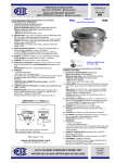
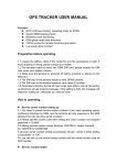
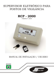
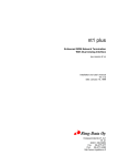
1234567890123456789012345678901212345678901234567890123456789012123456789012345678901234567890121
1234567890123456789012345678901212345678901234567890123456789012123456789012345678901234567890121
1234567890123456789012345678901212345678901234567890123456789012123456789012345678901234567890121
1234567890123456789012345678901212345678901234567890123456789012123456789012345678901234567890121
1234567890123456789012345678901212345678901234567890123456789012123456789012345678901234567890121
1234567890123456789012345678901212345678901234567890123456789012123456789012345678901234567890121
1234567890123456789012345678901212345678901234567890123456789012123456789012345678901234567890121
1234567890123456789012345678901212345678901234567890123456789012123456789012345678901234567890121
1234567890123456789012345678901212345678901234567890123456789012123456789012345678901234567890121
1234567890123456789012345678901212345678901234567890123456789012123456789012345678901234567890121
1234567890123456789012345678901212345678901234567890123456789012123456789012345678901234567890121
1234567890123456789012345678901212345678901234567890123456789012123456789012345678901234567890121
1234567890123456789012345678901212345678901234567890123456789012123456789012345678901234567890121
1234567890123456789012345678901212345678901234567890123456789012123456789012345678901234567890121
1234567890123456789012345678901212345678901234567890123456789012123456789012345678901234567890121
1234567890123456789012345678901212345678901234567890123456789012123456789012345678901234567890121
1234567890123456789012345678901212345678901234567890123456789012123456789012345678901234567890121
1234567890123456789012345678901212345678901234567890123456789012123456789012345678901234567890121
1234567890123456789012345678901212345678901234567890123456789012123456789012345678901234567890121
1234567890123456789012345678901212345678901234567890123456789012123456789012345678901234567890121
1234567890123456789012345678901212345678901234567890123456789012123456789012345678901234567890121
1234567890123456789012345678901212345678901234567890123456789012123456789012345678901234567890121
TomcoTechtips
ISSUE 2
TM
How to get the car to tell you what's wrong.
FIGURE A
Changing technology doesn't
always mean that your job will be
more difficult-it does mean it will be
different. For instance, if the car's
performance is poor, it may not be due
to plugs or points . It could be one of
the new performance controls such as
EGR valves, O2 Sensors, coolant
temperature sensors or ported vacuum
switches.
Actually, today's newer cars
with their on-board computers or
electronic control modules (ECMs)
make it easier to diagnose performance problems than ever before.
And believe it or not, one of the most
important tools you need is a paper
clip. If you know where to put the
paper clip, you can literally get new
GM cars to tell you what's wrong with
them.
What we will do here is give
you a brief "by the numbers" way to
read the on-board computers's self
diagnostic system for Chrysler and
GM. Each is a little different. We will
also give you a listing of the service
codes for these car makers. This
listing will give you a leg up on solving
performance problems on today's
newer cars.
GENERAL MOTORS
1. Locate the Assembly Line
Connecting Link (ALCL). You will
probably find it under the dash. This
is where the computer at the assembly plant hooks up to the car to
check out the systems.
2. Turn the ignition key to the "ON"
position, but do not start the engine.
3. Place the ends of a paper clip in
the A and B terminals of the
vehicle's ALCL (Fig A). This will
GM DIAGNOSTIC TERMINIAL/ALCL
CONNECTOR
1981
1980 1/2 4.3L
By simply inserting the two open ends of a paperclip in the proper teminal of the ALCL on GM
cars, the mechanic can start the trouble code
sequence. (The ECM may be damaged if the
wrong terminals are used. When in doubt, consult
the proper service manual.)
GROUND
DIAGNOSTIC TERMINIAL
GROUND
activate the system and the "Check
Engine" light will begin to flash.
Each flash is a digit in a code
number. it will flash once, pause,
then flash twice. This code is 12,
and it will flash the code three times.
4. Read the flashing codes. After
the three code 12's, the light will
begin to flash service codes for
components or systems which have
malfunctioned in the last 50 starts.
These codes will be repeated three
times each. If no malfunction exits,
the code 12 will flash until you
remove the paper clip.
CHRYSLER
You don't even need a paper clip to
get service codes from Chrysler
cars.
1. Turn the ignition key ON-OFF,
ON-OFF, on within 5 seconds. This
activates the system and the
POWER LOSS lamp will light up for
two seconds, immediately after
this, it will begin flashing the
service codes always starting with
code 88.
2. Count the flashes made by the
POWER LOSS light. Each one is
two digits (like GM). There is a
short pause between digits and a 4second pause between codes. The
light will continue to flash until all
codes in memory have been
displayed.
ECM TROUBLE CODE CHART
CHRYSLER
SERVICE
CODE
FORD
Since mid year 1978
models, Ford has used
several different versions of
two basic engine control
computer system; the
electronic Engine Control
(EEC) series and the Microprocessor Control Unit
(MCU) system. Some early
versions did not have self
diagnosis capabilities. The
Latter systems can be
checked using an analog
(pointer) type voltmeter or
scan tool. These systems
will be covered in a future
issue of TOMCO TECH TIPS.
The following chart
lists the service codes
and the components
or circuits they
indicate for Chrysler,
and GM. We have
condensed many
pages of information
in order to give you
this basic troubleshooting tool. Specific
service codes may be
found in service
manuals for each model
and year. This
chart is valuable to
get you headed the
right direction and it
is much handier than
searching through
large service
manuals.
GM
0
Oxygen Feedback Sys. Lean
---
1
Oxygen Feedback Sys. Rich
---
8
Knock Circuit
---
11
Distributor Signal
---
12
Battery Feed to Logic Module
Disconnected Recently
No Distributor Ref. Pulse or
Engine Speed Active
13
MAP Sensor (vacuum)
O2 Sensor Circuit
14
MAP Sensor (electrical)
Coolant Sensor High
15
Vehicle Speed Sensor
Coolant Sensor Low
16
Battery Voltage Sensing
---
17
Detonation Sensor, Engine Cooling Sys.
---
19
---
---
21
O2 Sensor
TPS, Idle & WOT Switch Error
22
ECT Sensor
TPS, Fuel cut-off Solenoid
23
Charge Temp Sensor,Throttle Body
Temp Sensor
M/C Circuit Solenoid, MAT
Sensor, Air Fuel Solenoid
24
TPS
Vehicle Speed Sensor
25
Auto. Idle Speed Control
MAT Sensor, Air Switch Solenoid
26
Injector 1 & 2 Fuel Injector Driver
---
27
Injector 3 & 4 Fuel Control
---
28
---
---
31
Canister Purge Solenoid Circuit
Wastegate Elec. Sig-Open,Wastegate Hi MAP Overboost, MAP Low
32
Power Loss Lamp, Power Limit Lamp
EGR, Baro Sensor, EVRV/EGR
33
A/C Wide Open Throttle Cut Relay Circuit Mass AIr Flow Sensor, MAP Sensor
34
EGR Solenoid , Speed Contol Solnoid
Speed Control Servo
Mass Air Flow Sensor, MAP Sensor,
Differential Pres. Vacuum
35
Radiator Fan Relay Circuit
ISC, Idle Air Control
36
Wastegate Conrol Solenoid
Burnoff Diagnostics
37
Trans. Lockup Solenoid, Baro Read
Solenoid, Shift Indicator Lamp
41
Battery Charging Sys. Altemator Field
Control
No Distrib Ref Signal, Cam Sensor
Failed, Cylinder Selsect Error
42
Auto Shut Down Relay
EST Monitor Error, By Pass Line Error,
Electronic Spark Control, Dist or C-3
Sys. Error, Fuel Cutoff Solenoid
43
Ignition & Fuel Control Interface Spark
Control
Electronic Spark Control
44
Logic Module Battery Temp.
Lean Exhaust (44 & 45 = O2 Sensor
45
Overboost
Rich Exhaust (44 & 45 = O2 Sensor
46
Battery Voltage Sensing
---
47
Battery Voltage Sensing
---
---
New EVP Sensor helps eliminate
sudden acceleration problems.
Some 1983 through 1986,
fuel injected Ford cars with 3.8 or
5.0 liter engines and automatic
transmission are experiencing
sudden acceleration.
The problem is believed to
be caused by the failure of the
EGR valve position. The sensor in
question is an early design for
which Ford now has a new specification.
Tomco, Inc. now offers an
EGR valve position sensor with an
improved design which conforms to
Ford's latest specifcations. Our
design has greater durability and a
longer service life. If you find one
of the old models on a car you are
servicing, it should be replaced with
the new design.
A note of caution. There
are replacement EGR valve
position sensors in the aftermarket
which are the very same units in
question. That is, they have the
old design which is no longer
specified by Ford. You will know
when you come across one of of
these, because the serial number
has been ground off the top of the
housing.
New Tomco, Inc. EVP Sensor, on left is white and has a rounded
housing. Old model on right has square housing. Also notice that the old
model on the right has had the serial number machined off. Do not install
an EVP Sensor that looks like this!
How to service the GM TBI pressure regulator.
There is no need to replace
the pressure regulator on GM TBI
units. Tomco, Inc. offers a kit that
allows you to safely service this
component. The kit also reduces
your parts cost while allowing you
to bill more labor.
Kit 3-272 contains two long
screws. When dismantling a
pressure regulator, first remove
only two short screws. Now
remove the long screws which
contol the extension of the regulator spring. This allows the housing
to be opened safely. These
screws also position the stamped
housing as the heavy regulator
spring is compressed and the short
screws are installed during reassembly. Also included are instructions and a special thread compound to prevent the screws from
loosening.
This kit complements our
TBI repair kit 5525 which contains
gaskets, seals, pressure regulator
diaphragm and filter. Complete
instructions are included.
8
6
3
11
7
1
4
12
5
9
10
2
1. THROTTLE POSITION SENSOR.
Outside of most carburetors and TBI
units (inside some GM carbs). Signals
computer how much air is being consumed. Check operation, adjust voltage
and inspect for corrision on connectors
every 25,000-30,000 miles. Failure
symptoms: Hesitations, tip in surge,
engine pinging, no torque converter
lock-up, "Check Engine" light is on.
4. OXYGEN SENSOR. Located on
exhaust manifold. Measures amount
of oxygen in exaust. Signals on-board
computer to adjust fuel mixture.
Check and replace according to
manufacturer's spectations. Bad
oxygen sensor may cause "Check
Engine" light to light up, poor
performance, reduced fuel economy,
and will damage catalytic converter.
8 IDLE SPEED CONTROL. Attached to
carburetor or TBI unit. Adjusts throttle
opening to maintain proper idle speed.
Inspect and adjust during tune-up
25,000-30,000 miles. Check for corrosion
on terminals. Failure symptoms: Engine
stalling and/or dieseling.
11. COOLANT TEMPERATURE SENSOR.
Located in vehicle coolant system. Major
component of computer-controlled
engines. Measures engine temperature.
Signals computer to adjust fuel mixture.
Inspect every 12,000 to 15,000 miles.
Bad sensors may cause poor performance, reduced fuel economy and hard
starting.
2. SEND FOR NEW ENGINE
PERFORMANCE CONTOL TAPE.
Get an overview of engine performance
controls in this 40 minute tape. Use it
as an update for yourself or your
mechanics. The tape covers location,
function and troubleshooting tips for
the 10 engine performance controls
pictured on this page. It also demonstrates the new EGR valve tester.
5. FUEL INJECTOR. Located in the TBI
assembly. Meters and atomizes fuel
delivered to engine. Inspect every
25,000-30,000 miles for proper
spray pattern and leakage. Failure
symptoms: No start, flooding,
hesitations, exhaust odor
9 EGR VALVES. Located on exhaust
manifold. EGR valves recirculate
exhaust gas to intake manifold to cool
peak combustion temperature. Reduce
NOX emissions. Inspect ever 12,000
to 15,000 miles. Bad EGR valve may
cause rough idle, overheating, loss of
power and poor fuel economy.
12. NEW EGR VALVE TESTER
AVAILABLE FROM TOMCO. This
hand-held tester allows positive
testing of all types of EGR valves. It
is easy to use, inexpensive and
operates on shop air. It comes with
complete instructions and storage
case.
3. AIR CHARGE & MANIFOLD AIR
TEMPERATURE SENSOR. Located in
the intake manifold or air filter housing.
Measures air/fuel mixture temperature.
Signals computer to adjust injector
for damage and corrosion when trouble
codes indicate problem in this circuit.
Failure symptoms: "Check Engine" light
is on continuously, hesitation, poor
mileage or strong exhaust odor.
6. IDLE AIR CONTROL. Located on TBI
unit or throttle body (PFI engines).
Minimizes the variation in engine speed
under various idle load conditions.
Check for proper idle control, free
pintle movement and corrosion on connectors every 25,000-30,000 miles.
Failure systems: Stalling, high
idle speeds. "Check Engine" light on
continuously.
7. EGR VALVE POSITION SENSOR.
Located on back of EGR valve. Signals
computer to adjust EGR valve opening.
Inspect when driveabilty problems
occur. Check for corrosion on terminals
every 25,000-30,000 miles. Failure
symptoms: Poor fuel economy, sudden
acceleration, hesitation.
10 PORTED VACUUM SWITCH. Located
in vehicle cooling system. Controls
various vacuum-actuated components,
including EGR valve. Inspect for
damage every 6,000 to 8,000 miles.
Test if engine overheats. Damaged or
broken swtches cause poor perform
ance, reduced fuel economy, surging,
and engine knock.