1
PSImulator2 User Manual
Table of Contents
1 System Requirements........................................................................................................................2
2 Launching Simulator GUI.................................................................................................................2
3 Frontend GUI.....................................................................................................................................2
3.1 Editor.........................................................................................................................................3
3.2 Simulator....................................................................................................................................4
4 Backend Shell....................................................................................................................................5
4.1 Filesystem..................................................................................................................................5
4.2 Interface Configuration..............................................................................................................6
4.3 DHCP Configuration.................................................................................................................6
4.3.1 Server.................................................................................................................................6
4.3.2 Client..................................................................................................................................7
4.4 DNS Server Configuration.........................................................................................................7
5 Connecting to a real network.............................................................................................................8
5.1 Requirements.............................................................................................................................8
5.2 Usage.........................................................................................................................................8
1 System Requirements
•
Java Runtime Environment version 7+
http://www.oracle.com/technetwork/java/javase/downloads/
•
Telnet client
Simulator GUI contains an in-built telnet client. You are however free to use telnet client of
your liking e.g. Putty (http://www.putty.org/) or the system command telnet.
2 Launching Simulator GUI
To start the Simulator GUI, double-click on the psimulator2_frontend.jar icon or use command:
java -jar psimulator2_frontend.jar
Warning:
Any change to the project structure (e.g. moving or renaming files) may cause undefined behavior.
3 Frontend GUI
The simulator graphical user interface consists of two modes. First of them is editor, which is used
to create and edit computer network models. The other is simulation mode which enables starting
simulation of a created virtual network. It is possible to control virtual device using a telnet client.
Simulation mode also enables capturing and reading network communication.
The simulator graphical interface has its own Help pages. To access them use the menu Help →
Help or simply press the F1 key.
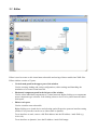
3.1 Editor
Editor is used to create or edit virtual network models and saving of those models into XML files.
Editor window consists of 3 parts:
•
Vertical main panel in the upper part of the window
Used to creating, loading and saving configurations, editor settings and launching the
simulation of a created virtual network
•
Horizontal component panel in the left part of the window
Used to select individual components of a virtual network. Right-clicking on a components
opens component type selection. Left-clicking selects a device to be placed onto the editor
work space.
•
Editor work space
Used to visualize network models.
Right-clicking on a virtual device and selecting option Properties opens an interface setting
window. Every interface can be set as either static or dynamic.
To set interface as static, enter a valid IPv4 address into the IP Address / mask field (e.g.
10.0.0.1/8).
To set interface as dynamic, leave the IP Address / mask field empty.
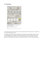
3.2 Simulator
After starting simulation from editor mode the frontend turns into simulation mode. Virtual device
are turned on during this process.
A simulation panel (shown above) will appear in the right side of the frontend window. You can
start capturing network communication by clicking the Capture button. Packets flowing in the
network will then appear in Event list part of the simulation panel. After clicking on a specific
packet record, details about this packet will be shown in the Selected packet details panel below.
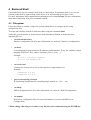
4 Backend Shell
Linux and CISCO devices contain a shell used to control them. If simulation mode is on, you can
connect to this shell by right-clicking on the device icon and selecting option Open telnet.
For more information about implemented commands use the command help. For more information
about linux commands, start given command with -h.
4.1 Filesystem
Linux-based devices contain a simple file system which allows to configure device using
configuration files.
To create and edit files, start the in-built text editor using the command editor.
Virtual file system structure is inspired by the linux distribution Debian. Amongst the most
important files are:
•
/etc/network/interfaces
Interface configuration file (For more information see section 4.2 Interface Configuration).
•
/etc/hosts
Local mapping between numerical IP addresses and hostnames. Every line contains a single
mapping in the form: IPv4_address hostname [alias1, alias2, …].
Example:
127.0.0.1 localhost loopback
10.0.0.1 www.example.com
•
/etc/resolv.conf
Contains list of nameservers. Every line specifies a single nameserver
Example:
nameserver 8.8.8.8
nameserver 8.8.4.4
•
/proc/sys/net/ipv4/ip_forward
IP forwarding confguration file containing single number (0 – off, 1 – on)
•
/etc/dhcp/
DHCP configuration files (For more information see section 4.3 DHCP Confguration)
•
/etc/named/
DNS server configuration files (For more information see section 4.4 DNS Server
Configuration)
! While editing a file using a text editor, every line has to be terminated using the ENTER key.
4.2 Interface Configuration
To change interface settings temporarily, use the ifconfig command.
The /etc/network/interfaces file is used for a permanent change.
•
Static interface configuration
Line: “iface interface_name inet static” followed by lines containing directives:
•
address – mandatory, specifes the IPv4 address on the interface
•
netmask – mandatory, specifies netmask
•
broadcast – optional, specifies broadcast address
•
gateway - optional, specifies default gateway
Example of a static interface configuration:
iface eth0 inet static
address 192.168.1.5
netmask 255.255.255.0
gateway 192.168.1.254
•
Dynamic interface configuration
A single line: “iface interface_name inet dhcp”
To confirm the changes, use the service networking restart command
4.3 DHCP Configuration
4.3.1 Server
The /etc/dhcp/dhcpd.conf file is used for DHCP server configuration. If this file does not exist, it is
possible to create it manually using a text editor, or entering the service dhcp-server start command,
which creates an empty dhcpd.conf file.
Structure of the dhcpd.conf file:
global parameters ...
subnet 10.0.0.0 netmask 255.0.0.0 {
subnet specific parameters ...
range 10.0.0.1 10.0.0.100;
range 10.0.0.150 10.0.0.200;
}
subnet 192.168.56.0 netmask 255.255.255.0 {
subnet specific parameters ...
range 192.168.56.10 192.168.56.50;
}
Implemented parameters include:
•
default-lease-time – default validity time of lease in seconds, 7200 is used if unspecified
•
max-lease-time – maximum validity time of lease in seconds
•
option lease-time – validity time of lease in seconds, default-lease-time value is used if
unspecifed
•
option domain-name-servers – a space-delimited list of nameservers IP addresses
•
option routers – a space-delimited list of routers
4.3.2 Client
If a connection between client and DHCP server exists, it is possible to lease an address in two
ways:
•
The dhclient command (e.g. dhclient eth0)
•
Changing the file /etc/network/interfaces (e.g. Adding the line: iface eth0 inet dhcp) and
restarting the networking service using service networking restart.
4.4 DNS Server Configuration
The main configuration file of a DNS server is located in /etc/named/named.conf. If case this file
does not exist, it is possible to create it manually using a text editor, or entering the command
service dns-server start, which will create an empty named file. This file specifies for which zones
does the server hold information.
Example of a zone definition in the named.conf file:
zone “example.com” {
type master;
file “/etc/named/zones/db.example.com”;
}
The zone parameter says that the following block will define the example.com domain. Inside this
block it is specified that this nameserver is a master server for given domain. The file parameter
specifies the full path to the zone file.
Example of a zone file:
; comment line
@
IN
SOA
$ORIGIN example.com.
www
IN
A
www.example.com. IN
test
IN
NS
ns
IN
A
@
admin 2002022401
10.0.0.1
A
10.0.0.10
ns.example.com
10.0.0.101
Lines are not terminated by semi-colon.
Every line except the SOA record is defined on a single line in the form:
label
IN
type
data
Label is a domain name terminated by a dot. If the last label character is not a dot, the domain name
is created by concatenating the label and domain specified in the ORIGIN directive. In case this
directive is not present earlier in the file, domain name is obtained from the value of the zone name
in the named.conf file.
It is also possible to specify the @ character as label. This characted will then be replaced by the
contents of the ORIGIN directive during parsing.
In this version of the simulator, there are two implemented record types: A, NS.
•
The A record maps a domain name given in the label section to a numerical IP address
specified in the data section.
•
The NS record specifies the name of an authoritative nameserver in the data section for
domain given in the label section.
5 Connecting to a real network
5.1 Requirements
•
Libpcap library (winpcap on OS Windows) – included in the project archive
•
jnetpcap library – can be downloaded at http://jnetpcap.com/download. After downloading,
extract the contents into Psimulator2 application directory. After that:
•
•
On OS Windows place jnetpcap.dll into C:\windows\system\
•
On linux-based system place jnetpcap.so into system shared libraries folder (typically
/usr/lib).
On linux-based system launch simulator frontend with root privileges
5.2 Usage
Place a real PC component into the network model. In its properties, select an output interface
which will be available on the host computer.
After starting the simulation, use command rnetconn to bind switchport of corresponding virtual
device to a real interface on the host computer. For more information about this command use
rnetconn help.
In order to successfully connect to a real network, the user is required to prevent limitations defined
on the real network. This means setting the same address of the second and third layers on the
interface connected to the real network. User is also needed to set routing on a simulated device
accordingly. In the case that user would want to communicate to the real network from multiple
different addresses or networks, it is needed to modify the system routing table accordingly.