1
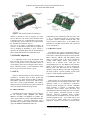
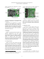
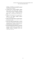
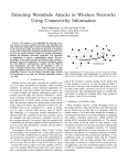
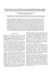
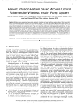
International Journal of Digital Content Technology and its Applications
Volume 3, Number 3, September 2009
A Wireless Sensor Networks Test-bed for the Wormhole Attack
Hani Alzaid1,2 and Suhail Abanmi3
1
Information Security Institute, Queensland University of Technology
Brisbane QLD 4000, Australia
2
Computer Research Institute, King Abdulaziz City for Science and Technology
Riyadh, Saudi Arabia
[email protected]
3
Computer Science College, University of New South Wales
Sydney NSW 2052, Australia
doi: 10.4156/jdcta.vol3.issue3.2
Abstract
program space, 1024 KB external flash, and is powered
by two AA batteries [3]. Also, the processing
capabilities in sensor nodes are generally not as
powerful as those in the nodes of wired networks.
Complex cryptographic algorithms consequently are
impractical for WSNs.
Not only resource limitations affect the WSN’s
performance but also the nature of deployment affects
this performance [1]. Most WSNs are deployed in
remote or hostile environments where nodes are
exposed to physical attacks. This is because anyone
can access the deployment area and these sensors lack
tamper-resistance property.
WSNs are vulnerable to several attacks. One major
attack is known as a wormhole attack where an
attacker records a packet at one location in the
network, tunnels the packet to another location, and
then replays it at another part of the network. The
wormhole attack places the attacker in a very powerful
position, allowing him to gain unauthorized access,
disrupt routing, or perform a Denial-of-Service (DoS)
attack [6,7].
Current solutions for wormhole attacks, such as
[10, 15, 16], are evaluated by running the proposed
techniques in different simulations. There is no real
deployment for any of these solutions. In this article, a
common ground or real deployment is built in order to
compare different solutions designed for protecting the
network against wormhole attacks. To the best of our
knowledge, the crisp implementation of the wormhole
attack in WSNs has not appeared in print before.
BANAID consists of a few
In some applications, wireless sensor devices must
be secured, especially when the captured information
is valuable and sensitive. The wormhole attack is a
significant type of security attack that can damage
wireless sensor networks if they go undetected. It
occurs when the attacker records packets at one point
of the network, and then passes them into a different
node. This node then injects the packets into the
network again. In this tutorial article, an actual test
bed called BANAID. It describes a simulated wormhole
attack against wireless sensor networks. In addition, a
recently developed solution against this attack is
implemented.
Keywords
Wireless Sensor Networks, Wormhole Attacks, and
Test-beds.
1. Introduction
Wireless Sensor Networks (WSNs) are highly
distributed networks of small, lightweight wireless
nodes. They are deployed in large numbers to monitor
the environment or other systems through the
measurement of physical parameters such as
temperature, pressure, or relative humidity [13, p 647].
Recently, WSNs have been used in many promising
applications including habitat monitoring [11], military
target tracking [8], natural disaster relief [2], and health
monitoring [12]. However, WSNs are resource
constrained with a limited energy lifetime, slow
computation,
small
memory,
and
limited
communication capabilities [17].
The current version of sensor nodes such as mica2
uses a 16 bit, 8MHz Texas Instruments MSP430
micro-controller with only 10 KB RAM, 48KB
19
A Wireless Sensor Networks Test-bed for the Wormhole Attack
Hani Alzaid and Suhail Abanmi
Figure 1. MICA2 mote without an antenna [4].
Figure 2. MIB510 Serial Interface Board [4].
numbers of Mica2 [4] and two Stargate [5] sensor
devices. Moreover, one of the current solutions, which
is Packet Leashes [9], is implemented in this article.
The preliminary version of this article was presented at
the AusCERT’08 conference [18,19].
The rest of the article is organized as follows. In
Section 2, an introduction about different components
used in building up BANAID is given. Section 3
describes the designing phase and the implementation
phase of BANAID. Section 4 concludes the article.
compatible and can communicate with each other. (The
x = 0, 1, or 2 depending on the type / frequency band)
[4]. Figure 1 shows a sample of MICA2 mote. The
current version of Mica2 uses a 16 bit, 8MHz Texas
Instruments, 1024 KB external flash, and is powered
by two AA batteries.
2.1.2 Hardware Layout
The MICA2 mote can be reprogrammed using an
external board called MIB510 Serial Interface Board.
This board is a multi-purpose interface board used with
MICA, MICA2, MICAz, and MICA2DOT motes
family. It supplies power to the devices through an
external power adapter option, and provides an
interface for a RS-232 mote serial port and
reprogramming port [4]. The MIB510 serial interface
board, as shown in Figure 2, is used to program the
MICA2 mote. This board has the PC connection
capability using the RS-232 serial port. Programming
the motes requires a special operating system called
TinyOS 1, which should be installed in the PC.
2. BANAID Components
It is important to have some background about
these wireless sensor devices that are used in this
article to build up the test bed. BANAID consists of
several Mica2 motes and two Stargate sensor devices.
In the following sections, a brief information about
these two types of wireless devices is given.
2.1 MICA2
There are different models of motes that have been
produced by Crossbow. Each of these models has
different features. These models are MICAz, MICA2,
MICA2DOT, and MICA. In this article, MICA2 is the
focus and is used to build BANAID. The features,
hardware layouts, and software environment of MICA2
motes are described in the following sections.
2.1.3 Software Environment
MICA2 motes use a special operating system called
TinyOS, which is used for wireless sensor nodes. This
operating system is an open-source event-driven
operating system designed for wireless embedded
sensor networks. It features a component based
architecture which enables rapid innovation and
implementation while minimizing code size as required
by severe memory constraints inherent in sensor
networks. TinyOS’s component library includes
network protocols, distributed services, sensor drivers,
and data acquisition tools – all of which can be used
as-is or can be further refined for a customized
application. TinyOS’s event-driven execution model
2.1.1 MICA2 Features
The MICA2 motes come in three types according to
the RF frequency bands: MPR400 (915 MHz),
MPR410 (433 MHz), and MPR420 (315 MHz). The
motes use the Chipcon CC1000, FSK modulated radio.
All types utilize a powerful Atmega128L microcontroller and a frequency tunable radio with extended
range. The MPR4x0 and MPR5x0 radios are
1
20
TinyOS website http://www.tinyos.net/
International Journal of Digital Content Technology and its Applications
Volume 3, Number 3, September 2009
enables fine-grained power management, yet allows
the scheduling
a WiFi Compact Flash card. Another expansion in
Stargate is MICA2 mote connector. It allows the
Figure 4. Processor Board (Bottom View) [5].
Figure 3. Processor Board (Top View) [5].
Stargate to communicate wirelessly with other
MICA2 motes. Stargate consists of two hardware
pieces: the processor board and the daughter card.
These pieces are explained in details in the following
subsection.
flexibility made necessary by the unpredictable nature
of wireless communication and physical world
interfaces [4].
TinyOS have been implemented in a language
called nesC 2 . This language is an extension to C
language which has been designed to embody the
structuring concepts and execution model of TinyOS.
Programs written in nesC language are built out of
components, which are wired to form entire programs.
Each component has interfaces which can provide its
functionality to other users.
2.2.2 Hardware Layout
As mentioned previously, Stargate consists of two
hardware pieces: a processor board and a daughter
board. Each of these pieces is described in this
subsection. Figure 3 shows the top view of the
processing board. It is clear from this view that
Stargate has two slots. These slots can be used to
communicate with other devices. The first slot is used
to allow Stargate to communicate with another MICA2
mote. The second slot is used to connect WiFi
Compact Flash card to the Stargate, which allows it to
communicate through the standard 802.11a or 802.11b
wireless protocols. The processor board gets its power
from the daughter card. The daughter card has a power
supply jack as it appears in Figure 5 and Figure 6.
Also, the daughter card allows the user to communicate
with Stargate using different types of interfaces. There
are three different ways to communicate with Stargate:
Serial RS232 Connector, RJ-45 Ethernet Port, and
USB Port. All these interfaces give the ability to
control or upload programs to the Stargate. All switch
buttons in the Stargate processor board and daughter
card have to be switched on before using Stargate.
There are two switch buttons (S1 and S2) in the
processor board and the third switch button S3 is
located in the daughter card.
2.2 Stargate
Stargate is a powerful single board computer with
enhanced communications and sensor signal
processing capabilities. This product was designed
within Intel’s Ubiquitous Computing Research
Program, and licensed to Crossbow for production. In
addition to traditional single board computer
applications, the Stargate directly supports applications
around Intel’s Open-Source Robotics initiative as well
as TinyOS based Wireless Sensor Networks.
2.2.1 Stargate Features
Stargate uses Intel’s latest generation 400 MHz
XScale processor (PXA255) and SA1111 StrongARM
companion chip for I/O access. It has a reset button,
real time clock, lithium ion battery option and 51-pin
daughter card interface [5]. The Stargate sensor device,
which is used in this test bed, has various features and
can be used in different applications. The main feature
that has been used extensively in the test bed is the
Compact Flash slot. Stargate has the capability to have
2.2.3 Software Environment
As mentioned before, the Stargate uses an
embedded Linux operating system kernel. It is installed
2
nesC: A Programming Language for Deeply
Networked Systems http://nescc.sourceforge.net/
21
A Wireless Sensor Networks Test-bed for the Wormhole Attack
Hani Alzaid and Suhail Abanmi
Each mote only forwards, without changing, any
received message from radio connection to WiFi
Figure 5. Daughter Card (Top View) [5].
Figure 7. The proposed designed of BANAID.
connection and vice versa. The routing algorithm that
has been used in BANAID is the Ad hoc On Demand
Distance Vector (AODV). This routing algorithm is
explained in the next subsection.
The wormhole attack happens during the phase of
building routes between nodes in AODV. The attack
will affect the routing table entries in the original
source and destination motes. Hence, the actual path
that a message should pass from, the original source to
the original destination, will be imprecise. The impact
of the wormhole attack on the network will appear
clearly in both the original source and the original
destination motes. The original source mote will deal
with the original destination mote as its direct
neighbor, which is incorrect because they are separated
by two intermediate motes.
Figure 6. Daughter Card (bottom View) [5].
on the processing board of the Stargate. There is also
additional software shipped with the Stargate
development platform, which could be used to enable
program development. The Stargate’s platform
provides the capability of installing programs written
in C language. The developer can control various
functions in Stargate by using C language programs
after compiling and installing them.
3. Building BANAID
3.2 The AODV Algorithm
The design, implementation, explanation of the
wormhole attack, and the implementation of its
solution are described in this section.
The Ad hoc On Demand Distance Vector (AODV)
routing algorithm is a routing protocol designed for ad
hoc mobile networks. It is an on demand algorithm,
meaning that it builds routes between nodes only as
required by source nodes. It maintains these routes as
long as they are needed by the sources.
AODV builds routes using route request and reply
query messages. When a source node desires a route to
a destination for which it does not already have a route,
it broadcasts a route request (RREQ) packet across the
network. Nodes receiving this packet update their
information for the source node and set up backwards
pointers to the source node in the route tables. A node
receiving the RREQ may send a route reply (RREP)
either if it is the destination or if it has a route to the
destination and the sequence number in RREQ packet
is fresh number (not seen before by the node). If this is
the case, it sends a RREP back to the source.
Otherwise, it forwards the RREQ. Nodes keep track of
3.1 Design of BANAID
The proposed test bed is developed with the
following underlying assumptions:
• The chosen network’s topology is fixed.
• Each node knows its neighbors.
Figure 7 shows that BANAID is composed of seven
Mica2 sensor nodes and two Stargate devices. In this
network design, the original source is mote 1 and the
original destination is mote 4. The global clock is a
normal sensor node that keeps sending a clock packet
to synchronize all other motes.
22
International Journal of Digital Content Technology and its Applications
Volume 3, Number 3, September 2009
the RREQ’s packets by storing their sequence
numbers. If they receive a RREQ which they have
already processed, they discard the RREQ and they do
not forward it.
As the RREP is propagated back to the source
node, these nodes set up forward pointers to the
destination. Once the source node receives the RREP,
it may begin to forward data packets to the destination.
The routing table for each node is updated according to
the hop count field in RREQ or RREP packets. The
received packet with the smallest hop count will be
chosen as the best route path.
However, in this article, not all of AODV routing
algorithm features have been implemented. Features
that meet the scope of this article are just implemented
for the sake of simplicity. For example, features like
sending and receiving RREQ/RREP packets, and
building the routing tables for each node have been
implemented whereas features like maintaining the
route paths and sending ‘hello’ messages have not been
implemented.
OS
Table 1. Packet Format.
C N HC MID MT
S/T
TS
Table 2. Routing Table Format.
Destination
Address
Node A
…
Next Hop
Hop Count
Node F
…
3
…
3.3.1 The AODV Program
Before describing the capabilities of this program, a
brief explanation about the important variables is
given. The packet format used in building the
wormhole attack test bed is composed of the following
fields (see Table 1):
• OS represents the address of the original sender.
• OD represents the address of the original
destination.
• C represents the address of the intermediate
sensor node or current node that handles the
current packet.
• N represents the address of the next-hop sensor
node.
• HC represents the hop counter.
• MID represents the messages ID.
• MT represents the message type.
• S/M explains whether the message comes from
a Stargate or a Mica2 sensor.
• TS represents time stamp.
3.3 Implementation of BANAID
According to the proposed design of BANAID,
there are seven MICA2 motes and two Stargate sensor
devices. Two motes have been combined with two
Stargate sensor devices which are mote 5 and mote 6.
Details on the implementation settings can be found in
[18].
To implement BANAID, three programs 3 have
been written and installed in the motes and the Stargate
sensor devices. The first program has been installed in
motes 1, 2, 3, and 4, which is a simple customized
AODV algorithm. The second program has been
installed in motes 5 and 6, which forwards any
received packet from the radio antenna to the serial
port that connects the mote with the Stargate, without
changing the received packet. The third program has
been installed in both Stargate 1 and 2. When a packet
is received by the Stargate from its serial port, which is
connected to the corresponding mote, the program
forwards it to the other Stargate through its WiFi
connection. The other Stargate will receive this packet
from its WiFi connection and forward it to its serial
port, which is also connected to the corresponding
mote. This packet then will be broadcasted via the
radio antenna of the attached mote.
3
OD
Next, Table 2 describes the routing table format. It
is a k * 3 array where k is a predefined value that
represents the maximum number of entries that the
routing table can hold. The table consists of three
fields: the destination address field which stores the
final destination for the current received packet, the
next hop field which holds the address for next hop,
and the hop count field which represents the number of
hops left before reaching the final destination.
Algorithm 1 illustrates the pseudo code that is used
in this article to implement AODV. It describes the
AODV’s functionalities that have been implemented in
order to build this test bed. It is the most important part
of the test bed since it implements the AODV routing
algorithm, synchronizes with the global clock, and
implements the solution for the wormhole attack. This
program has been written in combination of nesC and
C languages and is upload into mote 1,2,3, and 4.
These programs can be downloaded from
http://www.wsn-security.info/BANAID.rar
23
A Wireless Sensor Networks Test-bed for the Wormhole Attack
Hani Alzaid and Suhail Abanmi
Algorithm 1: Simplified version of the AODV
Program.
/* Initialization phase
*/
1: Synchronize internal clock with the global
clock;
2: Send PKT;
/* just for the source to start sending the packet*/
3: if ( PKT_MSG_Type = 0 ) then /* RREQ Mode
*/
4: { if ( PKT_MSG_ID is not in RREQ List )
then
5:
{ Add entry into Routing Table;
6:
Add PKT_MSG_ID into RREQ List;
7:
if
(
PKT_Orig_Destin=
Current_Mote_Address
) then
8:
preparing RREP PKT and send it;
9:
else forward PKT;
10:
}
11:
else { Check RT for PKT_Orig_Source and
get the Hop_Count;
12: if ( Hop_Count > PKT_Hop_Count ) then
13: {
update the entry in Routing Table;
14:
Send PKT;
15:
}}}
16: else if ( PKT_MSG_Type = 1 ) then
/* RREP Packet */
17: {
18: if ( PKT_MSG_ID is not in RREP List ) then
19: {
Add an entry into my RT (Routing
Table);
20:
Add PKT_MSG_ID into RREP List;
21:
if ( PKT_Orig_Destin=
Current_Mote_Address ) then
22:
{ RREP PKT reach it’s destination;
23:
send routing information for this
mote;
24:
}
25:
else forward PKT;
26:
}
27:
else
28:
{ Check RT for PKT_Orig_Source and get
the Hop_Count;
29:
if ( Hop_Count > PKT_Hop_Count )
then
30:
{ update the entry in Routing Table;
31:
Send PKT;
32:
}
33:
}
34: }
35: else if ( PKT_MSG_Type =2 ) then
36: {
37:
if
(
PKT_Orig_Destin
=Current_Mote_Address ) then
38:
packet reach its destination;
39: else
40:
{
41:
Check RT for PKT_Orig_Destin and get
Next_Hop ;
42:
Send PKT for the next hop;
43: }
44: } End;
3.3.2 TOSBase Program
This program is delivered with the TinyOS tool kit
as one of the many readymade applications. The name
of this application is TOSBase, which can be found
under the application directory in TinyOS file. It
simply forwards any received packet from the radio
antenna of the Mica2 sensor to the serial port (51-pin
Hirose Connector), which is shown in Figure 1,
without changing the content of the packet. The Mica2
sensor is connected to the Stargate through this serial
port. This program is written in nesC language and is
uploaded into mote 5, and 6 (see Figure 7).
3.3.3 Stargate Program
The program consists of two threads or processes.
The first process is the main program, which keeps
listening to the serial port and sends any received
packet to the client socket. The client socket will
initiate a WiFi connection with the server socket in the
other Stargate. The second thread or process runs as a
server that keeps listening to any client connection via
WiFi. It receives the packet and forwards it to the serial
port connected to the mote, which will broadcast the
packet via its radio antenna. As explained in Figure 9,
the program in Stargate 1 only forwards messages
received from the radio and comes from the original
source which is mote 1. The other Stargate only
forwards messages received from the radio that comes
from mote 4 which is the original destination. The two
versions of these programs are the same except in
checking the message type before forwarding it.
Algorithm 2: Stargate’s Program.
/* Initialization phase
*/
/*
*/
1: Open Serial port;
/*
The server runs forever to receive any MSG from
Stargate 2 with IP: 10.1.1.3, and then forwards it to
the serial port to be sent by a sensor node attached to
it via radio
*/
2: Run server thread with IP: 10.1.1.2;
3: While (1) do {
24
International Journal of Digital Content Technology and its Applications
Volume 3, Number 3, September 2009
the request packet comes before the reply. However, if
the yellow light has been seen before the green light, it
means a wormhole attack has been detected. The
reason for this is the replay comes before or faster than
the request packet. By using these lights, it is easier
now to understand what is happening during the
demonstration.
4: If (Stargate receive a MSG from the serial) then
/* the MSG comes from radio via mote 5 */
5: {
6: If (the MSG comes from mote 1) then
/* It is RREQ
*/
7: {
8:
Call client to forward MSG through WiFi to
Stargate 2;
9:
}
10: }
11: }
12: End.
Algorithm 3: TOBase’s Program.
/* Initialization phase
/*
1: Event#1: if (Radio receive MSG) then
2: {
3:
Call UARTSendTask to send MSG;
/* It will send MSG to the serial port
4:
}
5:
Event#2: if (UART receive MSG) then
6: {
7:
Call RadioSendTask to send MSG;
/* It will send MSG to the radio
8:
}
9:
End.
/*
The second Stargate
*/
/* Initialization phase
*/
/*
*/
1: Open Serial port;
2: Run server thread with IP: 10.1.1.3;
/* The server runs forever to receive any MSG from
Stargate 1 with IP: 10.1.1.2, and then forward it to
the serial port to be sent by a sensor node attached to
it via radio*/
3: While (1) do {
4: If (Stargate receive a MSG from the serial) then
/* the MSG comes from radio via mote 6 */
5: {
6: If (the MSG comes from mote 4) then
/* It is RREP
*/
7: {
8:
Call client to forward MSG through WiFi to
Stargate 1;
9:
}
10: }
11: }
12: End.
*/
*/
*/
*/
3.5 Visibility of BANAID
There are two scenarios for the running of
BANAID. The first scenario is demonstrating the
customized AODV routing algorithm without
implementing the wormhole attacks. In other words,
this scenario demonstrates the customized AODV
without the Stargate sensor devices. The second
scenario demonstrates the wormhole attack within the
customized AODV environments. To run the first
scenario, it is important to turn the Stargate sensor
devices off. The wormhole attack will not occur in this
scenario. To start this demonstration, firstly turn on
mote 2, 3, 4, and 7. Then, turn on mote 1 which acts as
the original source. Mote 1 will start sending RREQ
packet by blinking its green light. This sending will
occur after global clock synchronization is
accomplished. Mote 2 will receive the RREQ packet,
turn on its red light, and forward this packet by
blinking its green light. Mote 3 will do the same thing
that mote 2 has done. Finally, mote 4 will receive the
RREQ packet, turn on its red light and yellow light
indicating that the RREQ has reached its destination,
and prepare the RREP packet. The same process will
happen for RREP packet, but the difference is that each
mote will turn on its yellow light on receiving the
RREP packet. Finally, Mote 1 will turn on its red and
yellow lights on receiving the RREP packet indicating
that the RREP has reached its destination.
The other scenario is demonstrating the wormhole
attack by adding the two Stargate devices with their
3.4 Demonstration of BANAID
This section illustrates the usability of this test bed.
The Mica2 motes have some indicators which have
been used to simulate this type of attack. Each mote
has three lights: red, green, and yellow. These lights
have been used in this article to simplify the
demonstration of BANAID by showing how packets
are traveling from one mote to another and when the
wormhole attack happens. For example, when the
green light blinks, it means that the mote is sending a
packet. The red light indicates that the mote has
received a RREQ packet from the other motes. The
yellow light turns on when the mote has received a
RREP packet from the other motes. The green and
yellow lights together indicate that a RREQ or RREP
has been received at the destination. It is obvious that
the red light will be seen before the yellow light since
25
A Wireless Sensor Networks Test-bed for the Wormhole Attack
Hani Alzaid and Suhail Abanmi
motes. Firstly, turn on all motes and Stargates except
mote 1 which is the original source. Then, turn on mote
1 to start sending the RREQ packet. In this situation,
mote 4 which is the original destination will receive the
RREQ from mote 1 directly through the Stargate path
since the WiFi path is faster than the radio path. This
happens when Mote 5 receives the RREQ packet from
mote 1 and sends it directly through the WiFi
connection to the other Stargate. Mote 6 in the other
Stargate will send this packet to mote 4 via its radio
antenna. The RREQ packet will travel through the
WiFi connection faster than the normal path which
travels through motes 2 and 3. In this situation, mote 4
will think that mote 1 is its direct neighbor and it will
turn on its red light and yellow light preparing for the
RREP packet. Mote 4 will send the RREP packet and
then the packet will be delivered through the WiFi
connection between the two Stargates. Mote 1 will turn
on its red and yellow lights when it receives the RREP
packet. Also, mote 1 will think that mote 4 is its direct
neighbor and this is how the wormhole attack happens.
It is possible to display the information of the packets
and the final routing table in mote 1 by using a PC.
There are a number of techniques to solve the
wormhole attack in wireless sensor networks. In the
next section, some of these techniques are briefly
described. The implementation of one of them is
explained in section 3.7.
value in the packet. Therefore, the receiver will be able
to detect if the packet traveled so fast according to a
specified transmission time. In BANAID, the temporal
leash solution has been used and implemented to detect
and prevent the wormhole attack in the wireless sensor
network. The geographic leash solution has not been
considered in this article because it needs a special
hardware that can specify the locations of all nodes
such as GPS, which is expensive.
3.7 Implementation of the Packet Leashes
Solution
As it has been discussed earlier, timing mechanism
is required to distinguish if the packet received from
the fake path or the real path to avoid the wormhole
attack. A packet received from the Stargate is going to
be faster than the packet received from the mote since
the WiFi transmission is faster than the radio
transmission. Therefore, applying this timing
mechanism allows the destination to recognize the real
packet by comparing it’s time stamp with the time
stamp of the received packet. If the difference between
these two time stamps is less than or equal to a
predefined value (threshold), it means that it is a fake
packet. To compute the value of this threshold
according to BANAID design, we performed the
following:
3.6 Wormhole Attack Solution
• There is a transmission delay in each mote. The
average transmission delay is around 45 msec (
Tr = 45 msec ) [14].
• The real path consists of four sensor nodes
(N = 4), which are mote 1, 2, 3, and 4. On
the other hand, the fake path consists of four
sensor nodes, which are motes 1, 5, 6, and 4,
but only two sensor nodes will participate in
the transmission activities (N = 2). These two
nodes are mote 1, and mote 6.
• Processing time at each mote is neglected since
both paths have the same number of motes.
Therefore, the total processing time for motes
in each path is almost same.
• The WiFi transmission delay is neglected since
the data rate is high.
To detect and deter the Wormhole attack, some
solutions have been proposed in different papers such
as [9, 10, 15, 16]. Hu et al. proposed a defense against
the Wormhole attacks in WSN called packet leashes
[9]. It is the most commonly cited solution and
therefore it is the only solution that is implemented in
this article. A leash is a portion of information that is
added to the packet to restrict its traveling distance or
time. This solution consists of two types of leashes:
geographic leashes and temporal leashes. Each of these
types is described briefly in this section and more
details are available in Hu et al.’s paper [9].
A geographic leash detects and prevents the
wormhole attack by ensuring that the sender and the
receiver are within a specified distance. To do that,
each node must know its location and be timely
synchronized with other nodes. The other type of
solution is a temporal leash. It detects and prevents the
wormhole attack by ensuring that the packet’s traveling
time is within a specified period of time. To do that, all
nodes must be timely synchronized in terms of their
clocks. When the sender starts sending the packets, it
stores its sending time stamp in the packet. Then, the
receiver can compare its receiving time stamp with the
Thus, delay on the real path can be estimated as
follows:
Delay = N * Tr
= 3 * 45 = 145 msec (1)
On the other hand, delay on the fake path can be
estimated as follows:
Delay = N * Tr
= 2 * 45 = 90 msec (2)
26
International Journal of Digital Content Technology and its Applications
Volume 3, Number 3, September 2009
Therefore, the destination node is able to
distinguish between the real and the fake packet by
subtracting the time stamp at destination by the time
stamp at the source. If the result <= 90 msec (or <=
2Tr) then the packet is fake. Otherwise, it is real.
[2] Erdal Cayirci and Tolga Coplu. Sendrom: Sensor
networks for disaster relief operations management.
Wireless Networks, 13(3):409–423, 2007.
[3] Crossbow Technology, Inc. Mica2 datasheet, 2006. The
datasheet of Mica2 mote platform is retrieved 10th of
May
2009,
from
http://www.xbow.com/Products/Product_pdf_files/
Wireless_pdf
4. Conclusion and Future Work
[4] Crossbow Technology, Inc. MPR/MIB Mote Hardware
Users Manual. San Jose, CA, USA, May 30-31, 2005.
This user manual is retrieved 10th of May 2009, from
http://www.xbow.com/Support/Support_pdf_files/MPRMIB_Series_Users_Manual.pdf
[5] Crossbow Technology, Inc. Stargate Developer Manual.
San Jose, CA, USA, May 30-31, 2005. This Stargate
Developer Manual is retrieved 10th of May 2009, from
http://www.xbow.com/Support/Support_pdf_files/Stargat
e_Manual.pdf.
[6] Xiaojiang Du, Mohsen Guizani, Yang Xiao, and HsiaoHwa Chen. Defending dos attacks on broadcast
authentication in wireless sensor networks. In
Proceedings of IEEE International Conference on
Communications, ICC’08, Beijing, China, pages 1653–
1657, May 19-23, 2008.
[7] Saurabh Ganeriwal, Christina Pöpper, Srdjan Capkun,
and Mani B. Srivastava. Secure time synchronization in
sensor networks. ACM Transaction on Information and
System Security, 11(4), July, 2008.
[8] Tian He, Pascal Vicaire, Ting Yan, Liqian Luo, Lin Gu,
Gang Zhou, Radu Stoleru, Qing Cao, John A. Stankovic,
and Tarek F. Abdelzaher. Achieving real-time target
tracking using wireless sensor networks. In IEEE Real
Time Technology and Applications Symposium, pages
37_48. IEEE Computer Society, 2006.
[9] Yih-Chun Hu, Adrian Perrig, and David B. Johnson.
Packet leashes: A defense against wormhole attacks in
wireless networks. In INFOCOM: The 22nd Annual Joint
Conference of the IEEE Computer and Communications
Societies, Sun Francisco, USA, March 30 - April 3, 2003.
[10] Issa Khalil, Saurabh Bagchi, and Ness B. Shro_.
Liteworp: Detection and isolation of the wormhole attack
in static multihop wireless networks. Computer
Networks, 51(13):3750_3772, September, 2007.
[11] Alan M. Mainwaring, David E. Culler, Joseph Polastre,
Robert Szewczyk, and John Anderson. Wireless sensor
networks for habitat monitoring. In Proceedings of the 1st
ACM International Workshop on Wireless Sensor
Networks and Applications, WSNA'02, Atlanta, Georgia,
USA, pages 88_97, September 28, 2002.
[12] Aleksandar Milenkovic, Chris Otto, and Emil Jovanov.
Wireless sensor networks for personal health monitoring:
Issues
and
an
implementation.
Computer
Communications, 29(13-14):2521_2533, 2006.
[13] C. Siva Ram Murthy and B.S. Manoj. Ad Hoc Wireless
Sensor Networks Architectures and Protocols. Prentice
Hall PTR, Upper Saddle River, NJ, USA, 2004.
[14] Jeongyeup Paek, Krishna Chintalapudi, and Ramesh
Govindan. A wireless sensor network for structural health
The rapid development in the wireless sensor
networks field has allowed this technology to be used
in many applications. Some of these applications are
critical and require a secure and trusted environment.
Therefore, different research studies have been
conducted to analyze the wireless sensor networks and
discover their threats. One of the attacks which may
damage wireless sensor networks is the wormhole
attack. This article built a test bed of a group of sensor
devices to simulate the wormhole attack and
implement one of the solutions to detect and prevent
this attack. In this article, a brief background about the
types of wireless devices associated with BANAID is
introduced. Then, the design and the implementation of
BANAID are illustrated by describing the proposed
network topology, the algorithms, and the chosen
solution. Finally, detailed steps of setting up BANAID
are given. In future, the timing mechanism that has
been used might be improved especially with the new
version of TinyOS that gives the opportunity to
implement an internal clock in the mote. Also,
BANAID could be enhanced by some additional
improvements such as implementing and evaluating
different solutions for the wormhole attack, and
extending the size of the network implemented in
BANAID.
5. Acknowledgement
The authors would like to acknowledge Salil
Kanhere, Chun Tung Chou, and Wen Hu at CSE,
University of New South Wales for valuable comments
and for their support with setting environments for
TinyOS, Mica2, and Stargate. The authors also would
like to acknowledge Manal Alfaraj, Griffith University
and Teresa Desmarchelier, University of Queensland
for the valuable feedback on the article.
6. References
[1] Ian
F.
Akyildiz,Weilian
Su,
Yogesh
Sankarasubramaniam, and Erdal Cayirci. Wireless sensor
networks: a survey. Computer Networks, 38(4):393–422,
2002.
27
A Wireless Sensor Networks Test-bed for the Wormhole Attack
Hani Alzaid and Suhail Abanmi
monitoring: Performance and experience. In in
Proceedings of the 2nd IEEE Workshop on Embedded
Networked Sensors (EmNetS-II).
[15] Jeongyeup Paek, Krishna Chintalapudi, Ramesh
Govindan, John Ca_rey, and Sami Masri. A wireless
sensor network for structural health monitoring:
performance and experience. In EmNets'05: Proceedings
of the 2nd IEEE workshop on Embedded Networked
Sensors, pages 1_9, Sydney, NSW, Australia, May 30-31,
2005.
[16] Radha Poovendran and Loukas Lazos. A graph theoretic
framework for preventing the wormhole attack in
wireless ad hoc networks. Wireless Networks,
13(1):27_59, Feburary, 2007.
[17] Jennifer Yick, Biswanath Mukherjee, and Dipak Ghosal.
Wireless sensor network survey. Computer Networks,
52(12):2292_2330, 2008.
[18] Hani Alzaid, Suhail Abanmi, Salil Kanhere, and Chun
Tung Chou. Detecting wormhole attacks in wireless
sensor networks. Technical report, Computer Science and
Engineering School - University of New South Wales,
The Network Research Laboratory, July 2006.
[19] Hani Alzaid, Suhail Abanmi, Salil Kanhere, Chun Tung
Chou, and Faisal Alshuwair. BANAID: A sensor network
test-bed for wormhole attacks. In Proceedings of the
SETMAPE research and development stream of the
AusCERT conference, AusCERT'08, Gold Coast,
Australia, May 18-23, 2008.
28