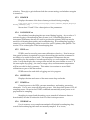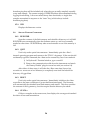
1
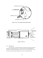
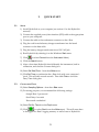
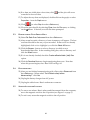
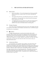
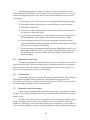
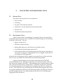
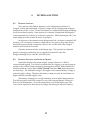
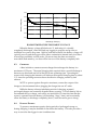
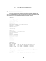
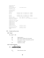
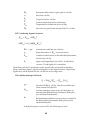
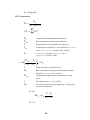
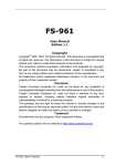
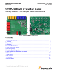
c- eta
Optical Attenuation and
Backscattering Instrument
User’s Manual
Revision J, Sept 17, 2004
Hydro-Optics, Biology, and Instrumentation Laboratories, Inc.
www.hobilabs.com
888-414-HOBI
888-414-4624
Current Firmware Version: 1.42
Other firmware versions may differ in some respects. Contact HOBI Labs for information
about firmware upgrades.
REVISIONS
Revision J, Sept 17, 2004: Correct formula for temperature correction of transmission
(12.2.5); other minor corrections and clarifications in section 12.
Revision I, May 20, 2004: Updated section 12 to reflect refinements in calibration
processing and HydroSoft, and improve equation formatting. Added section 5.3.
August 1, 2001: Updated Addresses, added alternative reset procedure to section 10.
February 23, 2001: Fixed dangling cross-references
February 21, 2001: Formatting, update section 13
February 6, 2001: Cosmetic changes.
January 20, 2001: Clarifications and corrections to formulas in sections, 12.2.3
December 12,2000: Corrected several typos.
December 1, 2000: First version separated from a-Beta.
ii
1.
INTRODUCTION................................................................................................................ 1
1.1.
1.2.
1.3.
1.4.
2.
Overview............................................................................................................................. 1
Backscattering (beta) Optics............................................................................................ 1
Attenuation Optics............................................................................................................ 1
Electronics........................................................................................................................... 2
QUICK START..................................................................................................................... 5
2.1.
2.2.
2.3.
2.4.
2.5.
3.
Setup.................................................................................................................................... 5
Collecting Data .................................................................................................................. 5
Downloading Data From c-Beta ..................................................................................... 6
Disconnecting .................................................................................................................... 6
Switch-Activated Logging ............................................................................................... 6
PRECAUTIONS AND MAINTENANCE........................................................................ 7
3.1.
3.2.
3.3.
3.4.
3.5.
3.6.
3.7.
4.
Precautions ......................................................................................................................... 7
General Cleaning .............................................................................................................. 7
eta Optics.......................................................................................................................... 7
Attenuation Optics............................................................................................................ 7
Pressure Transducer ......................................................................................................... 8
Connectors .......................................................................................................................... 8
Mounting and Deployment............................................................................................. 8
HYDROSOFT SOFTWARE ............................................................................................. 11
4.1.
4.2.
5.
Installing HydroSoft....................................................................................................... 11
Removing HydroSoft ..................................................................................................... 11
COLLECTING AND HANDLING DATA.................................................................... 13
5.1.
5.2.
5.3.
5.4.
5.4.1.
5.4.2.
5.4.3.
5.4.4.
5.5.
5.6.
5.7.
5.8.
Primary Data .................................................................................................................... 13
Housekeeping Data ........................................................................................................ 13
Calibration and Processing Setup................................................................................ 14
Connecting c-Beta ........................................................................................................... 14
Connection Dialog Box................................................................................................. 14
Manual Connection....................................................................................................... 15
Search Connection......................................................................................................... 15
Load Calibration From Instrument Option ............................................................... 15
Logging Setup.................................................................................................................. 15
Setting c-Beta’s Real-Time Clock................................................................................. 17
Logging Versus Real-Time Data .................................................................................. 17
Log Memory Capacity .................................................................................................... 17
iii
5.9. Using The External Switch ............................................................................................ 17
5.10. Downloading Logged Data ......................................................................................... 18
5.10.1. Basic Procedure ........................................................................................................... 18
5.10.2. Details ........................................................................................................................... 19
5.11. Processing Downloaded Data..................................................................................... 19
5.11.1. Making Calibrated Data Files.................................................................................... 20
5.11.2. Making Raw Decimal Files ........................................................................................ 21
5.12. Raw Data File Format ................................................................................................... 21
5.13. Calibrated Data File Format ........................................................................................ 21
6.
6.1.
6.2.
6.3.
6.4.
CALIBRATION DATA ..................................................................................................... 23
Loading Calibrations...................................................................................................... 23
Viewing And Editing Calibration Data...................................................................... 23
Sigma Correction............................................................................................................. 24
Converting B to bb ........................................................................................................... 24
7.
POWER AND DATA CONNECTIONS ........................................................................ 25
8.
INTERNAL BATTERY...................................................................................................... 27
8.1.
8.2.
8.3.
8.4.
9.
Battery Capacity............................................................................................................... 27
Battery Voltage and State of Charge............................................................................ 27
Charging............................................................................................................................ 28
Battery Disable ................................................................................................................ 28
DIRECT COMMUNICATION AND COMMANDS.................................................. 31
9.1. Communication Protocol ............................................................................................... 31
9.2. Command Syntax ............................................................................................................ 31
9.3. Command Replies........................................................................................................... 31
9.4. Routine Commands ........................................................................................................ 32
9.4.1. <ENTER> ....................................................................................................................... 32
9.4.2. BURST on........................................................................................................................ 32
9.4.3. BURSTLENGTH length................................................................................................. 32
9.4.4. BURSTCYCLE period..................................................................................................... 32
9.4.5. CLEARLOG.................................................................................................................... 32
9.4.6. DATAFORMAT,format ................................................................................................. 32
9.4.7. DIR................................................................................................................................... 32
9.4.8. DOWNLOAD cast ......................................................................................................... 33
9.4.9. ID ..................................................................................................................................... 33
9.4.10. PERIOD period.............................................................................................................. 33
9.4.11. RATE rate...................................................................................................................... 33
9.4.12. SLEEP duration............................................................................................................. 33
iv
9.4.13. START startDelay......................................................................................................... 33
9.4.14. STARTDELAY startDelay ........................................................................................... 34
9.4.15. STARTNOLOG............................................................................................................ 34
9.4.16. STOP.............................................................................................................................. 34
9.4.17. STOREFORMAT.......................................................................................................... 34
9.4.18. TIME mm/dd/yyyy hh:mm:ss ................................................................................. 34
9.4.19. XMODEM cast ............................................................................................................. 34
9.5. Additional Commands................................................................................................... 34
9.5.1. BAUD rate....................................................................................................................... 34
9.5.2. GAIN gain....................................................................................................................... 34
9.5.3. HEADER......................................................................................................................... 35
9.5.4. LOGHOUSE on.............................................................................................................. 35
9.5.5. PURE secs........................................................................................................................ 35
9.5.6. SLEEPINFO.................................................................................................................... 35
9.5.7. POWER on ...................................................................................................................... 35
9.5.8. VERBOSE on................................................................................................................... 35
9.5.9. VER.................................................................................................................................. 36
9.6. Special-Purpose Commands ......................................................................................... 36
9.6.1. BUILDDIR ...................................................................................................................... 36
9.6.2. QUIT................................................................................................................................ 36
9.6.3. RESET.............................................................................................................................. 36
9.6.4. STATS n .......................................................................................................................... 36
10.
TROUBLESHOOTING................................................................................................... 37
11.
RAW DATA FORMATS................................................................................................. 39
11.1. Decimal ........................................................................................................................... 39
11.2. Hexadecimal................................................................................................................... 39
11.2.1. Primary Data Packet ................................................................................................... 39
11.2.2. Housekeeping Data Packet ........................................................................................ 40
12.
CALIBRATION REFERENCE ....................................................................................... 43
12.1. Calibration data file format......................................................................................... 43
12.2. Calibration Equations .................................................................................................. 44
12.2.1. Depth............................................................................................................................. 44
12.2.2. Volume Scattering....................................................................................................... 44
12.2.3. Scattering Sigma Correction ...................................................................................... 45
12.2.4. Backscattering Coefficient.......................................................................................... 45
12.2.5. Attenuation .................................................................................................................. 46
13.
CUSTOMER SERVICE ................................................................................................... 49
v
vi
1.
1.1.
INTRODUCTION
OVERVIEW
c- eta is a self-contained instrument for measuring optical backscattering (bb)
and beam attenuation (c) in natural waters. In addition to the optics and electronics
to support the primary optical measurements, each c-Beta includes a depth
transducer, rechargeable batteries, a data logger with real-time clock, and an
external switch for controlling logging. The data logger supports a wide range of
sampling rates, as well as burst-mode sampling for collection over extended periods.
1.2.
BACKSCATTERING (BETA) OPTICS
The source beam originates from a light-emitting diode (LED) selected to
match the desired measurement wavelength. The beam from the LED goes through
a prism that bends the beam before it enters the water. The receiver consists of an
identical prism that bends the field of view toward the source beam, a bandpass
interference filter that determines the exact wavelength range of the measurement,
and a lens that focuses the received light onto a silicon detector.
The divergences of the source beam and receiver field of view, the angles of
the prisms, and the distance between the source and receiver windows, determine
the range of scattering angles over which the measurement is made. The c- eta
geometry results in a measurement centered on a scattering angle of 140°.
The fraction of the transmitted light scattered in the desired range of angles is
extremely small, and one of the prime considerations in the optical design is
maximizing this inherently low throughput. Thus we maintain a 2 cm open
aperture throughout the optical path.
1.3.
ATTENUATION OPTICS
The “c” side LED of c- eta is a folded-path beam transmissometer. A wellcollimated, 5 mm-diameter beam of light travels through the water to a solid glass
retro-reflector mounted on a rigid standoff. The retroreflector displaces the beam
and reflects it back to the instrument’s main housing. The round-trip distance
between the sensor face and the retro-reflector is the path length of the measurement
(nominally 30 cm, other path lengths optional). Any light scattered out of the beam
over that path length contributes to the measured attenuation.
1
Backscattering source LED
ON
Magnetic Switch
(shown in ON position)
MCBH8M Connector
Backscattering receiver
Figure 1 Front View of Backscattering (Beta) Endcap
16.02" [407mm]
AVOID OBJECTS
WITHIN 30° CONE
4.60" [117mm]
LIGHT BEAM
VOLUME OF
MAXIMUM SENSITIVITY
Attenuation Measurement Volume
Figure 2 Side View
1.4.
ELECTRONICS
The inherently low optical throughput of the backscattering measurement
demands very sensitive electronics. In clear water the backscattering signals
arriving on the backscattering detector may be as low as a few picoWatts. At the
same time, natural background light may be orders of magnitude larger.
2
To separate backscattering signals from background light, the LEDs are
modulated at audio frequencies, and synchronous receiver electronics used to
discriminate against interfering signals. To allow measurement in a wide range of
waters, and to accommodate the requirements of our calibration procedure, the
backscattering receiver gain can be set to one of 5 settings spaced a decade apart. ceta normally selects the appropriate gain automatically, based on the amount of
backscattering detected as well as the amount of background light.
3
2.
2.1.
QUICK START
SETUP
1) Install HydroSoft on your computer (see section 4.1 or the HydroSoft
manual).
2) Connect the supplied power/data interface (PDI) cable to the appropriate
port on your computer.
3) Connect the cable to the underwater connector on the c-Beta.
4) Plug the cord from the battery charger transformer into the barrel
connector on the data cable.
5) Plug the battery charger transformer into a 120 VAC jack.
6) Run HydroSoft by selecting it on the Windows Start menu.
7) Click
(or select Connect from the Instrument Menu).
8) Click the Search button.
9) After a short time HydroSoft should identify the instrument, load its
calibration, and close the Connect dialog box.
10) Select Set Date/Time… from the c-Beta menu.
11) Click Set Time to synchronize the c-Beta clock with your computer’s
clock. This will take several seconds. Then click Close to close the
Date/Time dialog box.
2.2.
COLLECTING DATA
12) Select Sampling Options… from the c-Beta menu.
13) For testing purposes, we recommend the following settings:
Sample Rate: 2 per second
Start Delay: 0 seconds
Burst mode: unchecked
14) Select Plot Vs. Time from the Graph menu.
(or select Start from the c-Beta menu). This will cause data
15) Click
to be logged in c-Beta’s logging memory as well as sent to HydroSoft.
5
16) If no data are visible after a short time, click
as needed to show all data.
, and the plot will zoom
17) To adjust the way data are displayed, double-click on the graph, or select
Properties… from the Graph menu.
18) Click
(or select Stop from the c-Beta menu).
19) Close the open data file by selecting Close from the File menu, or clicking
on the button. If desired, save the file when prompted.
2.3.
DOWNLOADING DATA FROM C-BETA
20) Select Get Data From Instrument from the c-Beta menu.
21) After several seconds a directory of casts in memory will appear. The last
cast listed should be the one you just recorded. If that cast is not already
highlighted, click on it to highlight it, or click the Select All button.
22) Click the Browse… button to select a directory in which to save
downloaded data files. In the resulting dialog box, select a directory and
click the Select button.
23) If it is not already checked, check the Create calibrated data (.dat) files
option.
24) Click the Download button to begin transferring data casts. Note that
when this process begins, the c-Beta’s LEDs will go off.
2.4.
DISCONNECTING
25) After you are finished communicating with c-Beta, select Disconnect from
the c-Beta menu. When asked “Put c-Beta to sleep before
disconnecting?” click Yes.
26) Unplug the battery charger from AC power.
27) Unplug the cable from c-Beta’s underwater connector.
2.5.
SWITCH-ACTIVATED LOGGING
28) To start a cast when c-Beta is asleep and disconnected from the computer,
move the magnetic switch to the on position (see Figure 1 on page 2).
29) To end a cast, return the magnetic switch to the off position.
6
3.
3.1.
3.2.
PRECAUTIONS AND MAINTENANCE
PRECAUTIONS
•
Protect the windows. Cover the instrument face whenever possible.
Do not use acetone to clean any part of the sensor, especially the
windows.
•
Thoroughly clean the sensor, especially the pressure port, with fresh
water after use. Be especially sure to clean and dry the instrument
before long periods of storage.
•
Avoid letting the sensor sit in direct sun. If the water temperature is
very different from the temperature on deck, let the instrument
stabilize in the water for 10 minutes before collecting data.
GENERAL CLEANING
Upon removing the instrument from salt water, rinse it thoroughly with fresh
water, and rinse the windows with distilled or deionized water. Periodically inspect
the windows for contamination.
3.3.
ETA OPTICS
The eta measurement uses an acrylic prism/window that is easily
scratched. Minor scratches will not seriously compromise the measurements, but
the windows must be treated carefully to avoid abrasion. Do not use acetone or
abrasive cleaners. Do not over-clean the windows. Unless the windows become
visibly dirty during use, it is usually sufficient to clean them once daily with soap or
alcohol and a soft cloth, then rinse them with clean water whenever they are
removed from the water.
3.4.
ATTENUATION OPTICS
The transmission optics include a large window on the main body of the
instrument, and the glass retroreflector separated from the sensor by an open
standoff. The attenuation optics require special care in cleaning, because attenuation
measurements are inherently sensitive to small changes in transmission through the
windows. When the c-Beta is deployed for intermittent profiling, it should be
thoroughly cleaned at least once per deployment day. Cleaning may be necessary
more often, depending on the turbidity of the water, and how frequently and
carefully the sensor is handled on deck. Be especially wary of deposits that may be
left by sea water or tap water.
7
All cleaning steps require clean, non-abrasive paper towels with low lint.
Some towel lint is tolerable if it can be blown away with pressurized air. Use a new
towel at the beginning of each step, and do not touch the windows directly with
your fingers.
1) Wash the windows with water and a mild liquid dishwashing detergent.
2) Thoroughly rinse all the soap away with distilled or deionized water.
3) Wipe the windows dry.
4) If any dirt or other contamination (other than loose lint) is still visible on
the windows, repeat the wash.
5) Apply ethanol or methanol to a towel. Wipe the window with the towel,
then immediately wipe away the alcohol with a second, dry towel.
6) Before putting the sensor in the water, thoroughly rinse the windows
again with distilled or deionized water, but do not wipe them (unless they
may have been dirtied in the interim).
7) Upon removing the instrument from the water, immediately rinse it very
thoroughly with fresh water. Avoid letting unpurified rinse water dry on
the windows. As soon as possible, rinse the windows with distilled or
deionized water.
3.5.
PRESSURE TRANSDUCER
The pressure transducer is underneath an array of four small holes in the face
plate on the Beta side. Before storing the sensor, flush the transducer with a gentle
stream of fresh water into the holes. A squeeze-bottle is ideal for the purpose. A
low-velocity stream from a hose is also acceptable.
3.6.
CONNECTORS
Occasionally spray the connector pins with silicone lubricant. The connectors
should mate smoothly without great force. Well-lubricated connectors also
disconnect fairly easily, so always use the locking sleeves. NOTE: use care to avoid
contaminating the optical windows with lubricant.
3.7.
MOUNTING AND DEPLOYMENT
c- eta can be suspended vertically from its metal eye, or strapped to another
support. If mounting to another structure, protect the finish on the case from direct
metal contact.
The eta side of the sensor is very sensitive to scattering from nearby objects.
Keep a 30-degree cone in front of the windows clear of any objects to avoid any
extraneous scattering. Even objects that appear very non-reflective, or are well out
of the nominal sampling volume, can create substantial offsets in the backscattering
8
measurement. However the degree of sensitivity depends on the object and its exact
position within the sensitive area. You may be able to determine non-interfering
locations by experiment.
It is usually preferable for the Beta side of the sensor to face directly down in
the water, to minimize the effect of background illumination. However in shallow
water over a reflective bottom, under bright solar illumination, light reflected into
the windows may cause high noise levels or, in extreme cases, saturation. In such
situations it may be advantageous to mount the sensor horizontally so that the
backscattering receivers do not face the bottom. Some experimentation may be
required in such cases.
9
4.
HYDROSOFT SOFTWARE
HydroSoft is HOBI Labs’ Windows-based software for communicating with
c-Beta as well as other instruments. Instructions in this manual assume you are
using HydroSoft to communicate with your c-Beta, and cover its primary functions.
You may wish to consult the separate HydroSoft manual for a more complete
description and details.
4.1.
INSTALLING HYDROSOFT
HydroSoft is supplied on a CD-ROM with new c-Betas, and can be supplied
on floppy disks by request. We also recommend you visit our web site
(www.hobilabs.com) to check for downloadable updates to HydroSoft. It is installed
using a procedure that is familiar to most Windows users.
1. Run “InstallHydroSoft.exe” from CD-ROM, or from your computer if you
have received it through the internet.
2. Click the “Next” button in the installer’s “Welcome” dialog box.
3. Decide whether you would like the HydroSoft application stored in the
default directory shown (normally c:\program files\HOBI Labs). If not,
click the “Browse” button to select a different directory, or type the name
of a new directory you would like to create.
4. Click “Next” to start the installation.
5. When the installation is complete, click “Finish” to exit.
It is not normally necessary to reboot your computer unless the installer
program explicitly instructs you to.
4.2.
REMOVING HYDROSOFT
1. From the Start menu, select “Settings”, then “Control Panel”.
2. Double-click on the “Add/Remove Programs” icon.
3. Select HydroSoft from the list of programs.
4. Click the “Add/remove” button.
OR
1. Open the directory into which you installed HydroSoft.
2. Double-click on the “unwise.exe” icon, which runs the un-installer.
11
5.
5.1.
COLLECTING AND HANDLING DATA
PRIMARY DATA
The primary data reported in every sample are
5.2.
•
date and time,
•
scattering,
•
the gain of the scattering channel,
•
transmission via the attenuation measurement path,
•
pressure, and
•
internal instrument temperature.
HOUSEKEEPING DATA
c- eta records certain “housekeeping” parameters that are not required for
normal data processing, but can be valuable for troubleshooting and for evaluating
the health of the sensor. They are
•
battery voltage (in V),
•
LED drive current (in mA),
•
background radiance on the detectors (in arbitrary units),
•
two additional internal temperatures (in C).
•
In live decimal data only, the charging current flowing into the battery is
also shown, in amperes. Charging current is not logged, and therefore is
not displayed with logged data.
Normally the housekeeping data are logged at one-tenth the rate of the main data.
That is, every ten samples are followed by one housekeeping sample.
Logging of housekeeping can be turned off through the LOGHOUSE
command (section 9.5.4). Although not advised for most circumstances, there are
two reasons this might be desirable. 1) Housekeeping data consume memory (about
10% of the memory devoted to primary data). 2) The time required to collect and
store housekeeping data can be significant at sampling rates above 5 samples per
second. Above that rate, the processing time for the housekeeping data may cause
the sample immediately following a housekeeping sample to be skipped, leading to
unstable sample intervals. For stable timing at rates above 5 Hz, housekeeping
logging should be turned off.
13
5.3.
CALIBRATION AND PROCESSING SETUP
Several settings within HydroSoft affect how the raw data from the
instrument are calibrated. We will list them here; for more details, see the
HydroSoft manual, as well as sections 6 and 12 of this manual.
Each instrument is supplied with a calibration file that quantifies its unique
characteristics. All the calibration information is also stored in the instrument’s nonvolatile memory, and by default HydroSoft loads it each time you connect (see
section 5.4.4). However you can manually select a different calibration file and even
edit the calibration for special purposes.
HydroSoft also gives you control over two aspects of the backscattering
calibration: sigma correction and conversion from volume scattering (N) to the
backscattering coefficient (bb), controlled by the Sigma Correction Parameters and
Backscattering Parameters dialog boxes, respectively. All these parameters are set to
sensible values by default, but sophisticated users may wish to adjust them for
certain applications.
5.4.
CONNECTING C-BETA
To communicate with a c-Beta, HydroSoft must open the appropriate
computer port at the correct baud rate. The following dialog box allows you to
control this process.
5.4.1. Connection Dialog Box
This dialog box appears each time you
•
select Connect from the Instrument menu,
•
click on the Connect button in a data window,
•
attempt an operation that requires a connection, if a connection has
not yet been established.
14
5.4.2. Manual Connection
If you click the Connect button, HydroSoft will open the currently selected
port at the selected baud rate. Normally you need not select an instrument type,
because HydroSoft will always request identification information from the
instrument. If it receives a reply sufficient to identify the instrument, it will proceed
with the connection and close the dialog box. If not, it will notify you and ask
whether to open the connection anyway. In you instruct it to, it will proceed on the
assumption that an instrument of the type you designate is connected.
5.4.3. Search Connection
If you click Search, HydroSoft will ignore the selected port and baud rate,
and attempt a connection to each port, at each baud rate (from 4800 to 57600), until it
receives valid identifying information from an instrument. Note that c-Beta’s
maximum baud rate is 38400, but HydroSoft searches at 57600 to accommodate other
possible instruments. The dialog box will automatically close if a valid connection is
found.
5.4.4. Load Calibration From Instrument Option
If Load Calibration From Instrument is checked at the time an instrument is
connected, HydroSoft will prompt the instrument to transmit the calibration
information stored in the instrument’s memory. This will override the currently
selected calibration file, if any. See section 6 for more information about calibration
files.
5.5.
LOGGING SETUP
c-Beta can be programmed to collect data continuously at rates from 0.1 Hz to
10 Hz, or intermittently to allow autonomous logging for long periods. In
HydroSoft, you can set these parameters in the following dialog box, which appears
when you select Sampling Options… from the c-Beta menu.
15
When the Sampling Options dialog is first open, it may take several seconds
for the current settings to be retrieved from the c-Beta. Similarly, when you click the
Apply button there will be a noticeable delay while HydroSoft transmits, then
confirms, the new settings. This confirmation is important because it allows you to
check that the settings were entered as you intended. The c-Beta may reject settings
it cannot support—for example, burst lengths that are longer than the burst interval.
Sample Rate and Sample Period, by definition, have an inverse relationship.
Changes you make to one will automatically affect the other. Note however that the
period, which has a resolution of 0.01 second, is the controlling parameter.
Therefore some exact sample rates are not available. For example, if you enter a rate
of 3 per second, the calculated period will be rounded to 0.33 s, and the rate will be
set to 3.03 per second.
When logging is started, either by software command or by turning on the
external switch, the c-Beta will wait for the number of seconds specified by Start
Delay, then data will be logged according to the given Sample Period. If burst mode
is on, the sampling continues until the Burst Length has elapsed, at which time the
sensor goes into its low-power sleep state. The bursts repeat according to the period
set by Burst Interval. Whether or not burst mode is on, sampling stops upon receipt
of a software stop command, when the external switch is turned off, or when the
battery becomes exhausted.
In the example above, the burst-mode parameters are inactive because burst
mode is not on. To edit the burst-mode parameters you must first check the Burst
Mode On option.
Before logging you may wish to download and clear data from c-Beta’s
memory (see section 5.10).
16
5.6.
SETTING C-BETA’S REAL-TIME CLOCK
Although it is not necessary for the sensor’s operation, you may wish to set
the real time clock before logging. Select Set Date/Time… from the c-Beta menu.
Click Set Time to synchronize the c-Beta clock with your computer’s clock. If you
wish to set the clock to a different time reference, select the Set Manually option and
enter the correct date and time before clicking Set Time. It takes several seconds for
HydroSoft to set the clock and reconfirm the setting. When it is finished, click the
Close button to close the dialog box.
5.7.
LOGGING VERSUS REAL-TIME DATA
Whenever collecting data in response to a Start command from HydroSoft, or from
its magnetic switch, c-Beta simultaneously transmits them from its serial port.
The STARTNOLOG command (section 9.4.15) can be used to start real-time
collection without internal logging. In HydroSoft, this command must be typed into
the terminal window.
Data can also be collected on demand, without internal logging, by sending a
carriage return or linefeed character each time a sample is required. See also section
9.4.1.
5.8.
LOG MEMORY CAPACITY
c- eta data are logged in a nonvolatile flash memory with a capacity of about
475,000 bytes (the exact memory size may vary from sensor to sensor). This
corresponds to 47,500 samples including housekeeping data, and about 52,000
samples without housekeeping data (see 5.2).
5.9.
USING THE EXTERNAL SWITCH
The external switch signals the sensor when to start and stop data logging.
When switched on, the c- eta will begin collecting data as if the START command
were sent to it. When switched off, it will stop sampling and go to sleep, as if the
STOP and SLEEP commands were sent.
RECEIVER
LIGHT SOURCE
SWITCH (SHOWN "ON")
17
By using the magnetic switch, one can collect an extended series of casts
without connecting to a computer. The starting and ending times of each cast are
recorded in the log memory so casts can be later downloaded individually or as a
group.
The sensor may be wakened from sleep by the serial port regardless of
whether the switch is “on” or “off”.
5.10.
DOWNLOADING LOGGED DATA
HydroSoft’s Get Data From Instrument command enables you to view a list
of casts stored in an instrument’s memory, transfer casts from the instrument to files
on your computer, and erase the instrument’s memory. Casts you transfer are
stored in individual files whose location and base name you specify. The cast
number is appended to the name of each file.
5.10.1. Basic Procedure
•
Connect the c-Beta to your computer’s com port using the supplied
data download cable, start HydroSoft, and use HydroSoft’s Connect
command to establish communication.
•
Select Get Data From Instrument on the c-Beta menu.
•
A dialog box like the following will appear.
•
After the directory is loaded, select the cast or casts you wish to
retrieve.
18
•
Enter a base file name for the downloaded files. The cast number will
be appended to this base name to create a unique name for each cast
you download.
•
If necessary, click Browse and select a destination directory for the
downloaded files.
•
Click Download. Depending on the quantity of data and baud rate,
downloading may take some time. Status messages and a graphical
indicator will show the download progress.
•
To clear the instrument’s memory after verifying the desired casts
were downloaded, click Delete All.
•
Click Close to dismiss the dialog box.
5.10.2. Details
Depending on the number of casts stored, loading the directory may take a
number of seconds. The status message in the upper left corner indicates if the
directory is loaded, as above, or if it is in the process of loading.
The memory status line indicates how much of the instrument’s memory is
presently used.
You can select arbitrary groups of casts for downloading. To select a
contiguous group of casts, click on the first item in the group, then shift-click on the
last item; or hold down the shift key while using the arrow keys. To select or
unselect non-contiguous casts, control-click on them; or hold down the control key
while using the arrow keys to move through the directory, and press the space bar to
select or unselect casts.
Data are always collected in raw form. If the Create calibrated data (.dat)
files option is checked, a calibrated file will also be created for each downloaded cast.
The calibration currently in effect for the main data window will be applied to these
data (see section 6 for more information about calibrations).
Because of the way c-Beta’s memory is configured, it is not possible to delete
individual casts—you can only erase the instrument’s entire memory.
5.11.
PROCESSING DOWNLOADED DATA
While HydroSoft allows you to save calibrated data automatically at the time
you collect or download data from a c-Beta, you can also process raw data files using
HydroSoft’s Process Raw Files command. This command also allows you to convert
raw hexadecimal data from a c-Beta to decimal form (see section 11.1) without
calibrating them.
When you select Process Raw Files, the following dialog box appears:
19
5.11.1. Making Calibrated Data Files
When Make Calibrated Files is selected, you need to specify a calibration file
to be used. You can type the path and name of the file directly, or use the Browse…
button to open an Open File dialog box. You must also select the file or files you
wish to process, using the familiar drive and directory list controls. The list in the
center right of the dialog box shows those files that are contained in the drive and
directory you specify, and whose names match the File name filter you specify. If
Show only files matching calibration file is checked, as it is by default, HydroSoft will
check the contents of the files and list only those that contain data from the
instrument type and serial number specified by the selected calibration file.
You can select a single file or an arbitrary group of files from the list. Select a
contiguous group of files by shift-clicking, and select or deselect individual files by
Ctrl-clicking. Once you start processing, all the selected files will be processed.
The processed files will use the same base names as the source files, with
their extensions set to “.dat”. They will be saved in the directory you specify. If you
wish to save them in the same directory as the raw files from which they are
generated, you can avoid having to select that directory manually by checking the
Same location as raw files option.
20
5.11.2. Making Raw Decimal Files
The process for making raw decimal files is identical to that described above,
except that there is no need for a calibration file. Controls relating to the calibration
file will thus be disabled.
When you select the Make Raw Decimal Files option, an additional Include
Housekeeping checkbox will appear, allowing you to control whether housekeeping
data will be included in the file in addition to the primary optical data.
5.12.
RAW DATA FILE FORMAT
HydroSoft names raw data files with the extension “.RAW”. Raw files start
with a header like the following:
[Header]
HydroSoftVersion=2.00
CreationDate=06/17/00 15:03:56
FileType=raw
DeviceType=c-Beta
DataSource=c-Beta
CalSource=d:\hsoft\test files\cb990907.cal
Serial=CB990907
Config=200
[EndHeader]
Future versions of HydroSoft may include additional information between
the [Header] and [EndHeader] markers. In any case, everything following the end
marker is included in the exact form in which it was received from the c-Beta. For
information on the raw data formats, see section 11.
5.13.
CALIBRATED DATA FILE FORMAT
HydroSoft normally names calibrated data files with the extension “.DAT”.
Calibrated data files start with a header like the following:
[Header]
HydroSoftVersion=2.00
CreationDate=06/17/00 15:11:41
FileType=dat
DeviceType=c-Beta
DataSource=c-Beta
CalSource=d:\hsoft\test files\cb990512.cal
Serial=CB990508
Config=200
[SigmaParams]
21
p=.6
[Channels]
"bb(532 nm)"
"c(532 nm)"
[ColumnHeadings]
Time,Depth,bb(532 nm),bb(532 nm)u,c(532 nm)
[Data]
36629.5892075231,-10.703,1.6972E-05,1.7092E-05,1.0358E-02
Future versions of HydroSoft may include additional information between
the [Header] and [Data] markers.
The line following [ColumnHeadings] names the parameters included in the
calibrated data lines. Future HydroSoft files may include additional column
headings and data parameters, but if so the parameters shown here will remain in
the same order.
Times are stored as double-precision real numbers corresponding to the
number of days since midnight, January 1, 1900. This is the native format of dates
and times in Microsoft Excel.
Depth is in meters, bb is in inverse meters, and is shown first in its “sigmacorrected” form, then in uncorrected form. c is also in inverse meters.
22
6.
CALIBRATION DATA
In general, data are received from c-Beta in raw form, and must be converted
to calibrated units. The coefficients required for this conversion are unique to each
instrument, and may be revised from time to time when the instrument is
recalibrated. HydroSoft requires an appropriate calibration to be loaded before it
can plot or store calibrated data from an instrument or raw data file.
6.1.
LOADING CALIBRATIONS
Calibrations can be loaded either directly from a connected c-Beta, or from a
file on the host computer. To load an instrument’s calibration, check the Load
Calibration From Instrument option while connecting to the instrument (see section
5.3). To load a calibration from a file, choose Select Calibration File from the File
menu.
If you select a new calibration file while an instrument is connected, or while
a raw data file is open, HydroSoft will only load it if it is of a matching type.
HydroSoft will inform you if the type does not match. It will also warn you if the
serial number of the instrument does not match that contained in the calibration file,
but it will offer you the option of loading it even if the serial numbers do not match.
Once a calibration file is loaded, it remains in effect until a different one is
loaded. When you exit HydroSoft, it stores the name of the current calibration file.
If the Automatically recall last selected calibration file option is selected in the
Preferences dialog box, the file will be reloaded the next time HydroSoft starts up. If
you have more than one data window open in HydroSoft, you can select a different
calibration file for each one. The most recently selected file in any window will be
saved as the default.
6.2.
VIEWING AND EDITING CALIBRATION DATA
You can see the details of the current calibration by selecting View Calibration
from the File Menu. Normally you should not need to modify calibration data for an
instrument, and the fields in the Calibration dialog box are locked to discourage
casual changes. However you can unlock most fields by clicking on the lock icon in
the dialog box. Because correct calibration files are critical to the accuracy of your
data, use care when modifying them. To reduce confusion we encourage you to
enter a description, in the comment field provided, of any changes you make.
To save a copy of the currently loaded calibration, select Save Calibration
from the File menu.
23
6.3.
SIGMA CORRECTION
Sigma correction is an adjustment to improve the accuracy of backscattering
measurements in highly-attenuating water. Some light that would otherwise be
detected as backscattering is lost to attenuation in the water between the instrument
and the detection volume, causing backscattering to be underestimated. We
compensate for this applying a correction function, P (Kbb), using equations shown in
section 12.2.3.
K bb is the coefficient of attenuation of the water within the sensor’s
measurement volume. For the c-Beta, HydroSoft estimates K bb by assuming that
K bb = p * c,
where the default value for p is 0.6, though HydroSoft allows you to enter different
values of p, or to specify another method of estimation.
6.4.
CONVERTING B TO bb
Single-angle backscattering instruments like c-Beta measure the volume
scattering function, N, at a particular angle, but the backscattering coefficient, bb is
often of most direct interest. Therefore HydroSoft’s default backscattering output is
an estimate of bb. HydroSoft gives you control over the parameters used to make
this estimate. See the HydroSoft User’s Manual for more details.
24
7.
POWER AND DATA CONNECTIONS
c- eta can be powered from three sources:
1) external 7V to 15V supply,
2) internal battery,
3) battery charger.
Any combination of these source may be safely connected simultaneously.
Power will be drawn from the source with the highest voltage. Nominal power
draw is 60 to 70 mA during sampling, and 1 mA during low-power sleep.
c- eta communicates via RS-232 through a standard computer serial port.
Power and data lines are brought out on a SubConn MCBH8M connector
(mate: MCIL8F), with pins assigned as shown below.
Face View of
Male Pins
MCBH8M
8
1
2
3
7
6
5
4
PIN
c- eta FUNCTION
1
Supply voltage (7 to 15 V)
2
Common
3
RS232 Instrument Receive
4
RS232 Instrument Transmit
5
Battery charging input (12 to 24 V)
6
Reserved
7
Reserved
8
Battery Disable (see 8.4)
The supplied cable splits into a DB9 for communication, a “barrel” connector
for the battery charger, and a pigtail for an external DC supply.
25
8.
8.1.
INTERNAL BATTERY
BATTERY CAPACITY
The capacity of the battery depends on the temperature at which it is
charged, stored, and discharged. Capacity is improved by charging and storage at
temperatures of 20 C or less. On the other hand, low temperatures during discharge
lower the realized capacity. Peak capacity for a battery charged and discharged at
room temperature is 36 hours of continuous operation. When discharged at 0 C, the
same charge provides at least 24 hours of operation.
In response to the external switch being turned off, a software command, full
memory, or a low battery condition, c- eta enters a low-power sleep state during
which their current drain is reduced to about 1 mA. In this state fully-charged
batteries will last about 2 months.
Capacity decreases slowly as the battery ages. The capacity loss depends
greatly on charging conditions, but is typically less than 10% after 200
charge/discharge cycles, and 20% after 500 cycles.
8.2.
BATTERY VOLTAGE AND STATE OF CHARGE
HydroSoft displays the current supply voltage whenever a c-Beta is
connected and logging. If a c-Beta is connected but not logging, you can prompt an
update of the current voltage reading by pressing the enter key while HydroSoft’s
terminal window is active (select Show Terminal from the c-Beta menu, then press
the enter key). The indicated voltage is the higher of the internal battery voltage or
external supply voltage. Therefore the battery voltage can only be read when it is
higher than the external supply, if any.
The battery voltage gives a rough indication of how much charge remains.
The following plot shows the voltage of a new, fully-charged battery, driving a cBeta at room temperature. At lower temperatures, and as the battery ages, this
curve can be expected to shift down in voltage, decreasing the effective capacity.
27
9.0
Battery voltage (V)
8.5
8.0
7.5
7.0
6.5
6.0
0
10
20
30
40
Discharge Time (hr)
ROOM-TEMPERATURE DISCHARGE VOLTAGE
When the battery voltage falls below 6.6 V, indicating it is virtually
completely discharged, c-Beta will halt any logging in progress and go into an
indefinite low-power sleep state. With its load thus reduced, the battery voltage will
typically recover and the logger will be able to maintain its internal state for at least
several days and likely several weeks. However since the data are stored in
nonvolatile flash memory, no data will be lost even if the battery completely fails.
8.3.
CHARGING
c- eta includes a constant-current charger that recharges the battery in a
maximum of 15 hours. The actual charging time required after a partial discharge is
between one third and one half of the full-power operating time. Operating the
sensor while charging the batteries will increase the required charging time by about
1/3, since the operating current reduces the effective charging current by that
amount.
NOTE: to protect against disruptive transients, connect the output of the
charger to the instrument before plugging the charger into an AC outlet.
While the battery tolerates indefinite periods of charging, repeated,
prolonged charges can eventually degrade battery capacity. For best battery life we
recommend that you charge, on average, not more than 1.5 times the time that the
sensor is operated from the battery (not including “sleep” time), and occasionally
allow the battery to discharge completely (that is, until the sensor goes to sleep).
8.4.
BATTERY DISABLE
To preserve maximum capacity during periods of prolonged storage or
during shipping, it may be desirable to disconnect the battery. This also provides a
way to reset the data logger in case it malfunctions.
28
The battery can be disconnected by shorting pins 2 and 8 of the underwater
connector, using the special dummy plug supplied. This special plug, distinguished
by a red band, must be removed and replaced with the black generic dummy plug to
permit battery-powered operation.
29
9.
DIRECT COMMUNICATION AND COMMANDS
c- eta is configured and controlled with commands sent via its serial
communication ports. When you use HydroSoft, the commands needed for routine
operation are generated automatically and you do not need to know the details.
However you can type commands manually, and view the c-Beta’s replies directly,
via HydroSoft’s terminal window or a generic terminal program. Some lesscommon commands are accessible only through this method.
9.1.
COMMUNICATION PROTOCOL
c- eta communicates through a standard RS-232 serial connection, with 8
data bits, no parity, one stop bit, and no handshaking.
The sensors default to 19200 baud, but can be set to other standard rates up to
38400 (see section 9.5.1).
9.2.
COMMAND SYNTAX
Each command takes a maximum of one numeric argument. Commands
always reply with the current value of any parameters, whether or not the parameter
value was supplied with the command. A comma or space may be included as a
separator before the argument, but is not required. For example, “POWER1”,
“POWER 1” and “POWER,1” are equivalent. Commands must end with a carriage
return and/or line feed. Commands are not case-sensitive, but are converted to
upper case as they are entered. Characters are also echoed as they are received.
NOTE: whenever the analog power is on (see section 9.5.7), it is advisable to
provide a delay of 1 ms or more between successive characters sent to the
instrument. HydroSoft introduces this automatically, and if you are typing
commands through a terminal there will be ample delay. If using custom software
to communicate you may need to introduce delays in the program.
9.3.
COMMAND REPLIES
Every command produces a reply, some consisting of more than one line. If
the command sets operational parameters, the reply will include the current settings
of those parameters.
Most lines sent by the sensor (decimal data lines being an important
exception) begin with a character that indicates the nature of the message:
•
Apostrophe (‘) indicates a routine parameter or other informational message.
•
Exclamation point (!) indicates an error or urgent message.
•
Asterisk (*) indicates a hexadecimal data packet.
31
If the sensor receives a command it does not understand, it will reply by
echoing the command, preceded by an exclamation point and followed by a
question mark. For example, sending
DESTRUCT<enter>
Prompts the reply
!DESTRUCT?
9.4.
ROUTINE COMMANDS
9.4.1. <ENTER>
Sending the <enter> character alone causes the sensor to immediately send a
line of data in the currently set data format. See also sections 9.4.6 and 011.
9.4.2. BURST on
Controls burst-mode logging. If on is nonzero burst mode is active. BURST
also displays the values of burstlength and burstcycle, which are set with their own
commands. Also see section 5.3.
9.4.3. BURSTLENGTH length
Length is the duration of each sampling burst, in seconds. Also see section
5.3.
9.4.4. BURSTCYCLE period
Period is the number of minutes from the start of one sampling burst to the
start of the next. Also see section 5.3.
9.4.5. CLEARLOG
Erases the entire contents of log memory. Before proceeding, requires the
user to confirm by typing “YES” (all upper case).
9.4.6. DATAFORMAT,format
Sets numeric format of data packets to either decimal or hexadecimal. The
argument format may be a letter H or numeral 1 for hexadecimal, D or zero for
decimal. If a letter argument is used, it must be separated from the command by a
comma. To set the default data format used when the sensor is reset, use
STOREFORMAT (section 9.4.17).
9.4.7. DIR
Displays a directory of casts in log memory, in the following format:
Cast
Start time
Duration
Samples
1
03/31/1999 18:39:48
6 secs
5
2
03/31/1999 18:43:48
25 mins
4305
32
3
03/31/1999 19:30:48
5 secs
5
9.4.8. DOWNLOAD cast
Starts download of the data in cast. If no cast is specified, downloads all casts
in sequence. At the beginning of each cast, also sends the starting time of the cast
and a header (see the HEADER command) containing column names for the data.
Note that the analog power of the sensor turns off during download to
conserve power and prevent the background sampling process from slowing the
download. The power automatically turns back on if a cast is started with the switch
or START command. It can also be restored with the POWER command.
9.4.9. ID
Displays the serial number used to uniquely identify each sensor.
9.4.10. PERIOD period
Sets the sampling period in seconds. The period may range from 0.1 to 10
seconds, with 0.01 s resolution. This may also be set in terms of a frequency, with
the RATE command. Also see section 5.3 for more information about logging
parameters. If you intend to sample with periods of 0.2 or less, see section 5.2,
Housekeeping Data.
9.4.11. RATE rate
Sets the sampling rate in Hz. The rate may range from 0.1 to 10 Hz. This
may also be set in terms of time rather than frequency, with the PERIOD command.
If you intend to sample at rates of 5 or higher, see section 5.2, Housekeeping Data.
9.4.12. SLEEP duration
Puts the sensor into low-power sleep mode. If no duration is specified, the
sensor will sleep until wakened by either serial communication or the magnetic
switch. Switching off the magnetic switch automatically executes the SLEEP
command.
9.4.13. START startDelay
Starts a cast, with the first sample being logged after startDelay seconds. If no
delay is specified, the last entered delay is used. This parameter can also be set with
the STARTDELAY command. After the delay, sampling proceeds in accordance
with the RATE/PERIOD and BURST parameters.
If analog power is off (see section 9.5.7), it will turn on immediately upon
receipt of START.
Waking the sensor with the external switch automatically executes the
START command.
33
9.4.14. STARTDELAY startDelay
Sets and displays the default delay used by the START command, or when
logging is initiated by the external switch. This setting is overridden if a delay is
later specified with the START command.
9.4.15. STARTNOLOG
Starts sampling in accordance with the PERIOD and BURST settings, but
without logging the results to memory.
9.4.16. STOP
Ends a cast and stops sampling. STOP does not automatically turn off analog
power. Turning off the external switch automatically executes STOP, followed by
SLEEP.
9.4.17. STOREFORMAT
Makes the current data format the default setting so it will remain in effect
even if the sensor is reset. See section 9.4.6.
9.4.18. TIME mm/dd/yyyy hh:mm:ss
Sets the c- eta real-time clock. TIME accepts partial dates and/or times as
arguments. For example, TIME 3:45 will set the time to 3:45 without affecting the
date; TIME 10/23 will set the date to October 23 without affecting the time or year.
9.4.19. XMODEM cast
Prepares c- eta to start an Xmodem transfer. If a cast is specified, that cast
will be transferred. If no cast is specified, the entire contents of the log memory will
be transferred.
To complete the transfer, the terminal program used to communicate with ceta must support Xmodem transfers. After sending the XMODEM command to ceta, you must initiate the transfer with an appropriate command to the terminal
program.
9.5.
ADDITIONAL COMMANDS
9.5.1. BAUD rate
Changes the baud rate to the given rate. Valid rates are 300, 600, 1200, 2400,
4800, 9600, 19200 and 38400, but note that HydroSoft does not support rates below
4800. The default rate is 19200.
9.5.2. GAIN gain
Sets the gain of the backscattering channel. A gain value of 1 through 5 fixes
the gain at that level. Setting gain to zero (the default), turns on automatic gain
34
selection. The reply to gain indicates both the current setting, and whether autogain
is turned on.
9.5.3. HEADER
Displays the names of the data columns produced during sampling:
time,beta,gain,trans,press,temp1,battV,LEDdrv,Bbgnd,Tbgnd,M
BTemp,LEDTemp,chg
See sections 5.1 and 5.2 for a description of the parameters.
9.5.4. LOGHOUSE on
Sets whether housekeeping data are stored during logging. An on value of 1
activates logging of housekeeping data; 0 turns it off. Housekeeping data are
instrument parameters that are not used to produce the primary data, but may be
useful for evaluating data quality and troubleshooting. If housekeeping logging is
turned on, one housekeeping packet is saved for each 10 primary data packets. See
section 5.2 for a description of the housekeeping data.
9.5.5. PURE secs
PURE is used to record a pure-water calibration value for c. Note however
that special software is required to process the resulting data and the command is
not likely to be useful for most users. The instrument will measure the raw
transmission for the number of seconds specified by secs and compute the average
value. It will then display the average value and ask the user whether to save it. If
the user replies by typing Y, the time, average value, and instrument temperature
will be recorded in the log memory. This makes it convenient to record field
calibrations as part of the data stream.
PURE can not be used while a logging cast is in progress.
9.5.6. SLEEPINFO
Displays the time and cause of the most recent sleep and wake.
9.5.7. POWER on
Controls power to the LEDs, pressure transducer, and analog processing
electronics. If on is zero, turns off the analog power. Note that when power is off, all
sampling ceases. However the START command automatically turns power on in
preparation for sampling.
Sampling is stopped and the analog power turned off whenever data are
downloaded, in order to reduce the load on c-Beta’s microprocessor.
9.5.8. VERBOSE on
If on is nonzero, every sample transmitted will include housekeeping data,
even if the housekeeping data were not actually sampled. If on is zero,
35
housekeeping data will be included only when they are actually sampled, normally
every tenth sample. The current setting of VERBOSE affects data transmitted during
logging downloading. It does not affect binary data downloads, or single data
samples transmitted in response to the “enter” key (which always include
housekeeping data).
9.5.9. VER
Displays the firmware version.
9.6.
SPECIAL-PURPOSE COMMANDS
9.6.1. BUILDDIR
Scans the contents of the flash memory and rebuilds a directory to it in RAM.
BUILDDIR runs automatically when the firmware starts up, and is not normally
needed at other times. BUILDDIR may take several minutes to run if the memory is
full.
9.6.2. QUIT
Used only under special circumstances. Immediately quits the c-Beta’s
internal operating program and returns to the TFX-11’s # prompt. If the user should
accidentally type this command, the c- eta can be restarted by one of two methods.
1) In Hydrosoft’s Terminal window, type control-R
2) Remove the communication cable from the instrument and attach
the ‘Battery Disable’ plug for several seconds (see section 8.4).
After either of these steps, it will take the c-Beta some time (from a few
seconds to a worst case of two minutes) to completely reset itself and rebuild its
directory of logged data.
9.6.3. RESET
Used only under special circumstances. Immediately initializes the c- eta
controller to the same condition as if power had been interrupted. The firmware
will automatically be reloaded from flash memory and started. This does not affect
the contents of the log memory, but does require that the directory be rebuilt.
9.6.4. STATS n
Collects n samples at the current rate, then displays the average and standard
deviation of beta and transmission.
36
10.
TROUBLESHOOTING
If your c-Beta does not respond to its external switch and HydroSoft is unable
to wake and detect it, you may need to reset its microprocessor. In most cases this
will not affect the data stored in its memory.
1) Connect the battery charger or another external power source.
2) Check that the c-Beta is properly connected to the computer.
3) Select the Reset command from HydroSoft’s Instrument or (c-Beta) menu,
making sure that it is addressing the port to which c-Beta is connected.
4) Wait for 2 minutes after the reset completes before attempting to
reconnect.
The serial ports on some computers, especially laptops, do not produce
enough voltage to guarantee this procedure will work. An alternative is to directly
apply a voltage of approximately 9V to the DB9 serial connector on the data interface
cable while it is connected to the c-Beta. Apply the positive side of the voltage
source to pin 3 of the DB9 connector, and the negative side to pin 5. You may have
received a device for this purpose, with a 9V battery attached to a DB9 male
connector, with your c-Beta. If so, simply plug this device into the interface cable for
about 30 seconds, then wait for 2 minutes before attempting to reconnect with the
computer.
If you cannot perform the above procedures, use this alternative:
1) If it is possible the battery is discharged, connect the charger for at least 30
to 60 minutes.
2) Disconnect the charger from AC power.
3) Disconnect the data cable from c-Beta’s underwater connector.
4) Plug the special dummy plug (designated by a red or yellow handle) into
the underwater connector for 10 seconds. If the special plug is not
available, directly short pins 2 and 8 together (see section 8.4).
5) Remove the dummy plug and reconnect the data cable to the computer.
37
11.
RAW DATA FORMATS
Raw data can be sent in either hexadecimal or decimal format. HydroSoft
sets the sensors to hexadecimal format by default. The format is set by the
DATAFORMAT command (section 9.4.6).
11.1.
DECIMAL
Decimal data, whether downloaded from memory or produced in real time,
arrive in the following format. See section 5, and the following sections, for
descriptions of these parameters.
time, raw scattering, gain, raw transmission, raw pressure, temperature1, battery
voltage, LED drive current, scattering receiver background, transmission receiver
background, temperature2, temperature3, [charging current]
11.2.
HEXADECIMAL
Two types of hexadecimal data packets are defined; one for primary data and
one for housekeeping.
11.2.1. Primary Data Packet
Example: *C251A748C29FFFB1FFFA24001015D7C<CR><LF>
Parameter
Type
Packet Flag
Packet ID
Time (secs)
Time (0.01
secs)
Beta
Beta gain
Transmission
Pressure
TempRaw
Checksum
Terminator
*
char
C
signed
HHHHHHHH
unsigned HH
signed
unsigned
signed
signed
unsigned
ASCII
HHHH
H
HHHHHH
HHHH
HHH
HH
<CR><LF>
TOTAL:
ASCII
Bytes
1
1
8
2
4
1
6
4
3
2
2
34
Example
*
C
251A748C
29
FFFB
1
FFFA24
0010
15D
94
Each data packet begins with an asterisk character. Other transmissions, for
example replies to commands, may begin with other characters. The packet type is
identified by a ‘C’ in the next position.
39
The time value is in seconds since Midnight, January 1, 1980, assuming the cBeta’s real-time clock has been set correctly. When c-Beta is reset (for example, by
having its battery disabled), the time value will be reset to zero and advance from
there. The first 8 hexadecimal digits show the whole number of seconds, while the
last 2 show the fractional part of the time in hundredths. The fractional time never
exceeds 99 (63 hex).
The next value, Beta, is the raw backscattering signal, presented as a 16-bit
signed integer. This is followed by a value between 1 and 5 that indicates the gain
setting that applies to the beta value. c-Beta adjusts the gain automatically according
to the scattering values measured and ambient light conditions.
Transmission is a 24-bit signed integer indicating the raw transmission of the
a optical path. Calibrated values are calculated as documented elsewhere.
Pressure is a signed 16-bit integer. The depth in meters is calculated by
depth (m) = (Pressure – depthOffset) * depthCoefficient
The values of depthCoefficient and depthOffset are specified in the
calibration file provided with each instrument.
TempRaw indicates the c-Beta’s internal temperature. The actual temperature
is calculated by
Temp (C) = TempRaw / 10 – 10
TempRaw is an unsigned 9-bit number with a range of 0 to 511, giving the
calibrated temperature a range of –10 to 41.1 C.
Checksum is the least significant byte of the sum of all the ASCII bytes
preceding the checksum in the packet, not including the packet flag (*).
This packet and all other transmissions are terminated with a carriage return
and line feed.
11.2.2. Housekeeping Data Packet
Example: *I60209327194B801EE1B8<CR><LF>
Param
Type
ASCII
Packet Flag
Packet ID
RawV
RawDrive
Bbgnd
Tbgnd
char
unsigned
signed
unsigned
unsigned
*
I
HH
HHHH
HH
HH
ASCII
Bytes
1
1
2
4
2
2
40
Example
*
I
60
2093
27
19
MBTempRa unsigned HHHH
w
LEDTempRa signed
HHHH
w
Checksum
HH
Terminator
<CR><LF>
TOTAL
4
4B80
4
1EE1
2
2
24
20
Like the primary data packet, the housekeeping packet begins with an
asterisk. It is distinguished from other packets by the character “I” in the second
position.
RawV is an unsigned 1-byte integer that indicates the supply voltage of the cBeta. To convert it to volts, divide by 10. The calibrated value has a range of 0 to
25.5V.
RawDrive indicates the current flowing through the LEDs. It is a 16-bit
signed integer (although in practice it is never negative). To convert to actual
current in mA, multiply this number by 0.00382.
Bbgnd and Tbgnd indicate the output voltage from the front end of the beta
and transmission receivers, respectively, presumably due to background radiance.
They are unsigned bytes with arbitrary units.
MBTempRaw and LEDTempRaw are unsigned 16-bit integers indicating the
readings from two additional temperature sensors, on the motherboard and LED
driver board. To convert to actual temperature in C, multiply by 0.00382 and
subtract 50.
Checksum and Terminator are the same as in the “C” packet.
41
12.
12.1.
CALIBRATION REFERENCE
CALIBRATION DATA FILE FORMAT
HydroSoft normally loads calibration data directly from the a-Beta, but can
also store and read them in text files with the following format. The parameters and
their sequence may vary somewhat depending on software versions.
[General]
DeviceType=c-Beta
Serial=CB991113
Label=Sample File
Config=200
MaxDepth=320
CalTime=627124816 (11/15/99 09:20:16)
DepthCal=5.27564E-03
DepthOff=2311.19
[Scattering]
Lambda=532
DeltaLambda=10 <Informational>
Gain1=0.103098301
Gain2=1
Gain3=10.85966445
Gain4=100.0800938
Gain5=948.7336892
Offset1=-3
Offset2=-3
Offset3=2
Offset4=2
Offset5=30
Mu=0.00125904
Sigma1=0.993
<may not be used in HydroSoft 2.7+>
Sigma2=0.131
<not used if SigmaExp is present>
Sigma3=0.0138
<not used if SigmaExp is present>
SigmaExp=0.150 <not present in some earlier files>
ChiBb=1.0807
<user can override this within HydroSoft>
TempCoeff=0
<often zero>
CalTemp=22.7
MuRho=1.1
<not present in some earlier files>
43
[Attenuation]
Lambda=532
DeltaLambda=10
<Informational>
TrNought=-98
TrPure=224876
CalTemp=22.3
Path=0.3
Chi0=0
<always zero or absent for c-Beta>
Chi1=0
<always zero or absent for c-Beta>
Chi2=0
<always zero or absent for c-Beta>
Chi3=0
<always zero or absent for c-Beta>
aPure=0.0447
<not used for c-Beta>
BetaPure=0.0001735
<not used in later HydroSoft versions>
TempCoeff0=99678
TempCoeff1=58.63664
TempCoeff2=3.1768
TempCoeff3=0
TempCoeff4=0
TempCoeff5=0
KDepthCoeff0=0
<usually zero>
KDepthThreshold=0
<usually zero>
KDepthCoeff1=0
<usually zero>
[End]
12.2.
CALIBRATION EQUATIONS
12.2.1. Depth
D = k D (P P0 )
D
P
P0
Depth (meters)
Raw pressure reading from instrument
Raw pressure offset at atmospheric pressure
(DepthOff in .cal file)
kD
DepthCal in .cal file
12.2.2. Volume Scattering
140
=
µ (S raw S 0 g )
(1 + kT (T
S raw
Tcal ))Gg
Raw backscatter value
44
S0 g
Backscatter dark offset for gain g (from .cal file)
µ
Mu (from .cal file)
kT
T
Tcal
Gg
TempCoeff (from .cal file)
Current temperature (from instrument)
Temperature at calibration (from .cal file)
Gain ratio for gain (Gain1 through Gain5 in .cal file)
12.2.3. Scattering Sigma Correction
140
=
140u
(K bb )
(K bb ) = k1 exp(kexp K bb )
K bb = pc
p
kexp
Attenuation coefficient (see c below)
Beam attenuation to
K bb conversion factor
Coefficient characteristic of the individual instrument,
stored in the .cal file
k1
Sigma1 and SigmaExp from .cal file. In HydroSoft
versions 2.7 and higher, k1 is calculated
HydroSoft versions 2.5 and earlier used a second-order polynomial formulation,
using coefficients Sigma1, Sigma2 and Sigma3, for the sigma function. Sigma2 and
Sigma3 may still be included in the .cal file but are no longer used
12.2.4. Backscattering Coefficient
bb = 2
bb
(
140
140 w
) + bbw
bb
Stored as ChiBb in .cal file. May be overridden by a
value entered in HydroSoft.
140w
Volume scattering of pure water at 140 degrees, as
entered in the Backscattering Parameters dialog box
(see the HydroSoft Manual).
bbw
Backscattering coefficient of pure water, as entered in
the Backscattering Parameters dialog box (see the
HydroSoft Manual).
In HydroSoft prior to version 2.53, the following was used
45
bb = 2
bb
140
12.2.5. Attenuation
Trraw
(T ) (Tcal )
TrT =
5
(T ) =
ktnT n
n =0
TrT
Trraw
T
Tcal
Temperature-compensated transmission
Raw transmission value from instrument
Temperature from instrument (in degrees C)
Temperature at which Trraw was measured (CalTemp
from [Attenuation] section of the .cal file)
ktn
TempCoeff1 through TempCoeff6 (kt0 =
TempCoeff1) (from .cal file)
c = ln
Tr pure
TrT
c
Tr0
Tr0 1
Tr0 l
cP
Beam attenuation coefficient (m-1)
Raw transmission reading with transmission path
blocked (TrNought from .cal file)
Trpure
Temperature-compensated transmission in pure
water
l
Path length (m) (Path in .cal file)
cP
Pressure-induced change in apparent c, (not present
on most instruments).
if P V PK:
K P = k p0
P P0
PK P0
if P > PK:
46
K P = k p0 +
k p0
(k
p1
K p 0 )(P
PFS
P0 )
PK
Initial slope of apparent K versus raw pressure
change (KDepthCoeff0 in .cal file)
P
P0
PK
k p1
Raw pressure reading from instrument
Raw pressure offset at atmospheric pressure
(DepthOff in .cal file)
Raw pressure reading above which the slope
changes from kp0 to kp1. (DepthThreshold in .cal
file)
Slope of apparent K versus raw pressure, when
pressure exceeds PK. (KDepthCoeff1 in .cal file)
47
13.
CUSTOMER SERVICE
If your c-Beta needs to be returned to HOBI Labs for repair, maintenance or
calibration, contact HOBI Labs customer service ([email protected] or call the
main office) with the following information at hand:
•
Instrument Serial Number
•
Reason for return
•
Method of return (Federal Express, United Parcel Service, etc.)
•
Point of contact
•
Date needed (standard turnaround is three to four weeks)
•
Delivery address
HOBI Labs will notify you of estimated cost and turnaround time as soon as possible
after receiving the instrument. Repairs will not be started until you approve the cost
estimate and turnaround time.
For technical support or questions about your instrument, contact our
technical support department at [email protected] or call our main office.
49