1
S I T E
M O N I T O R I N G
Alert EL
for SiteScan® SS2000W
Alarm
Management
System
USER’S MANUAL
Contents
Introduction to Alert EL
1-1
How To Use This Manual . . . . . . . . . . . . . . . . . . . . . . . . . . . . . . . . . . . . . . . . . . . . . . . . . . . . . . . . . . . . . . . . . . 1-1
What Is Alert EL? . . . . . . . . . . . . . . . . . . . . . . . . . . . . . . . . . . . . . . . . . . . . . . . . . . . . . . . . . . . . . . . . . . . . . . . . 1-2
Multiple Views . . . . . . . . . . . . . . . . . . . . . . . . . . . . . . . . . . . . . . . . . . . . . . . . . . . . . . . . . . . . . . . . . . . 1-2
Unlimited Alarms . . . . . . . . . . . . . . . . . . . . . . . . . . . . . . . . . . . . . . . . . . . . . . . . . . . . . . . . . . . . . . . . . 1-2
Multi-User Capability . . . . . . . . . . . . . . . . . . . . . . . . . . . . . . . . . . . . . . . . . . . . . . . . . . . . . . . . . . . . . 1-2
Minimum Requirements . . . . . . . . . . . . . . . . . . . . . . . . . . . . . . . . . . . . . . . . . . . . . . . . . . . . . . . . . . . . . . . . . . . 1-3
Minimum Software Requirements . . . . . . . . . . . . . . . . . . . . . . . . . . . . . . . . . . . . . . . . . . . . . . . . . . . . 1-3
Minimum Hardware Requirements . . . . . . . . . . . . . . . . . . . . . . . . . . . . . . . . . . . . . . . . . . . . . . . . . . . 1-4
Windows Considerations . . . . . . . . . . . . . . . . . . . . . . . . . . . . . . . . . . . . . . . . . . . . . . . . . . . . . . . . . . . 1-4
Installing Alert EL . . . . . . . . . . . . . . . . . . . . . . . . . . . . . . . . . . . . . . . . . . . . . . . . . . . . . . . . . . . . . . . . . . . . . . . 1-5
The Alarm Process . . . . . . . . . . . . . . . . . . . . . . . . . . . . . . . . . . . . . . . . . . . . . . . . . . . . . . . . . . . . . . . . . . . . . . . 1-8
The FB Generates An Alarm . . . . . . . . . . . . . . . . . . . . . . . . . . . . . . . . . . . . . . . . . . . . . . . . . . . . . . . . 1-8
The FB Transmits the Alarm to the Gateway Module . . . . . . . . . . . . . . . . . . . . . . . . . . . . . . . . . . . . . 1-8
The Gateway Module Delivers the Alarm to the Alert Server on the Alert Receiving Station . . . . . 1-10
Alert Server Delivers the Alarm to Alert EL . . . . . . . . . . . . . . . . . . . . . . . . . . . . . . . . . . . . . . . . . . . 1-11
Alert EL Stores the Alarm Information in the Alert Database . . . . . . . . . . . . . . . . . . . . . . . . . . . . . . 1-11
Alert EL displays the alarm according to the current view . . . . . . . . . . . . . . . . . . . . . . . . . . . . . . . . 1-12
The alarm may go through various states before being closed in Alert EL . . . . . . . . . . . . . . . . . . . . 1-12
The alarm is "closed" by Alert EL after all requirements are fulfilled . . . . . . . . . . . . . . . . . . . . . . . 1-13
Preparing to Receive Alarms . . . . . . . . . . . . . . . . . . . . . . . . . . . . . . . . . . . . . . . . . . . . . . . . . . . . . . . . . . . . . . 1-13
SiteScan 2000 for Windows and Alert EL . . . . . . . . . . . . . . . . . . . . . . . . . . . . . . . . . . . . . . . . . . . . . 1-13
SiteScan 2000 for Windows alc.ini Settings . . . . . . . . . . . . . . . . . . . . . . . . . . . . . . . . . . . . . . . . . . . 1-13
Connection Configuration . . . . . . . . . . . . . . . . . . . . . . . . . . . . . . . . . . . . . . . . . . . . . . . . . . . . . . . . . 1-14
Configuring the Database . . . . . . . . . . . . . . . . . . . . . . . . . . . . . . . . . . . . . . . . . . . . . . . . . . . . . . . . . . 1-15
Configuring the Station . . . . . . . . . . . . . . . . . . . . . . . . . . . . . . . . . . . . . . . . . . . . . . . . . . . . . . . . . . . 1-16
Configuring GFBs With Alert Microblocks . . . . . . . . . . . . . . . . . . . . . . . . . . . . . . . . . . . . . . . . . . . . 1-17
Running Alert EL . . . . . . . . . . . . . . . . . . . . . . . . . . . . . . . . . . . . . . . . . . . . . . . . . . . . . . . . . . . . . . . . . . . . . . . 1-18
Launching Alert EL for the First Time . . . . . . . . . . . . . . . . . . . . . . . . . . . . . . . . . . . . . . . . . . . . . . . 1-19
Logging In . . . . . . . . . . . . . . . . . . . . . . . . . . . . . . . . . . . . . . . . . . . . . . . . . . . . . . . . . . . . . . . . . . . . . . . . . . . . 1-22
The Main View . . . . . . . . . . . . . . . . . . . . . . . . . . . . . . . . . . . . . . . . . . . . . . . . . . . . . . . . . . . . . . . . . . . . . . . . . 1-25
Title Bar . . . . . . . . . . . . . . . . . . . . . . . . . . . . . . . . . . . . . . . . . . . . . . . . . . . . . . . . . . . . . . . . . . . . . . . 1-25
Menu Bar . . . . . . . . . . . . . . . . . . . . . . . . . . . . . . . . . . . . . . . . . . . . . . . . . . . . . . . . . . . . . . . . . . . . . . 1-25
Alarm Display . . . . . . . . . . . . . . . . . . . . . . . . . . . . . . . . . . . . . . . . . . . . . . . . . . . . . . . . . . . . . . . . . . 1-26
Alert EL User’s Guide
Contents • 1
Configuring the Database
2-1
Introduction . . . . . . . . . . . . . . . . . . . . . . . . . . . . . . . . . . . . . . . . . . . . . . . . . . . . . . . . . . . . . . . . . . . . . . . . . . . . . 2-1
Configuration Pop-Up . . . . . . . . . . . . . . . . . . . . . . . . . . . . . . . . . . . . . . . . . . . . . . . . . . . . . . . . . . . . 2-2
Configuration Commands . . . . . . . . . . . . . . . . . . . . . . . . . . . . . . . . . . . . . . . . . . . . . . . . . . . . . . . . . . . . . . . . . . 2-3
Add . . . . . . . . . . . . . . . . . . . . . . . . . . . . . . . . . . . . . . . . . . . . . . . . . . . . . . . . . . . . . . . . . . . . . . . . . . . . 2-3
Change . . . . . . . . . . . . . . . . . . . . . . . . . . . . . . . . . . . . . . . . . . . . . . . . . . . . . . . . . . . . . . . . . . . . . . . . . 2-4
Delete . . . . . . . . . . . . . . . . . . . . . . . . . . . . . . . . . . . . . . . . . . . . . . . . . . . . . . . . . . . . . . . . . . . . . . . . . . 2-6
Copy . . . . . . . . . . . . . . . . . . . . . . . . . . . . . . . . . . . . . . . . . . . . . . . . . . . . . . . . . . . . . . . . . . . . . . . . . . . 2-7
Close . . . . . . . . . . . . . . . . . . . . . . . . . . . . . . . . . . . . . . . . . . . . . . . . . . . . . . . . . . . . . . . . . . . . . . . . . . . 2-8
Operators . . . . . . . . . . . . . . . . . . . . . . . . . . . . . . . . . . . . . . . . . . . . . . . . . . . . . . . . . . . . . . . . . . . . . . . . . . . . . . . 2-9
Configuring the Operator Table . . . . . . . . . . . . . . . . . . . . . . . . . . . . . . . . . . . . . . . . . . . . . . . . . . . . . . 2-9
Sort List By - For Operator Records . . . . . . . . . . . . . . . . . . . . . . . . . . . . . . . . . . . . . . . . . . . . . . . . . 2-14
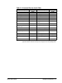
Systems . . . . . . . . . . . . . . . . . . . . . . . . . . . . . . . . . . . . . . . . . . . . . . . . . . . . . . . . . . . . . . . . . . . . . . . . . . . . . . . 2-15
Configuring the System Table . . . . . . . . . . . . . . . . . . . . . . . . . . . . . . . . . . . . . . . . . . . . . . . . . . . . . . 2-15
Sort List By - For System Records . . . . . . . . . . . . . . . . . . . . . . . . . . . . . . . . . . . . . . . . . . . . . . . . . . . 2-17
Sites . . . . . . . . . . . . . . . . . . . . . . . . . . . . . . . . . . . . . . . . . . . . . . . . . . . . . . . . . . . . . . . . . . . . . . . . . . . . . . . . . 2-19
Configuring the Site Table . . . . . . . . . . . . . . . . . . . . . . . . . . . . . . . . . . . . . . . . . . . . . . . . . . . . . . . . . 2-19
Sort List By - For Site Records . . . . . . . . . . . . . . . . . . . . . . . . . . . . . . . . . . . . . . . . . . . . . . . . . . . . . 2-22
Actions . . . . . . . . . . . . . . . . . . . . . . . . . . . . . . . . . . . . . . . . . . . . . . . . . . . . . . . . . . . . . . . . . . . . . . . . . . . . . . . 2-23
Overview . . . . . . . . . . . . . . . . . . . . . . . . . . . . . . . . . . . . . . . . . . . . . . . . . . . . . . . . . . . . . . . . . . . . . . 2-23
When A Reporting Action Is Changed . . . . . . . . . . . . . . . . . . . . . . . . . . . . . . . . . . . . . . . . . . . . . . . 2-24
Sort List By - For Reporting Actions . . . . . . . . . . . . . . . . . . . . . . . . . . . . . . . . . . . . . . . . . . . . . . . . . 2-27
Groups . . . . . . . . . . . . . . . . . . . . . . . . . . . . . . . . . . . . . . . . . . . . . . . . . . . . . . . . . . . . . . . . . . . . . . . . . . . . . . . . 2-28
Configuring the Group Table . . . . . . . . . . . . . . . . . . . . . . . . . . . . . . . . . . . . . . . . . . . . . . . . . . . . . . . 2-28
Sort List By - For Groups . . . . . . . . . . . . . . . . . . . . . . . . . . . . . . . . . . . . . . . . . . . . . . . . . . . . . . . . . . 2-30
Alarms . . . . . . . . . . . . . . . . . . . . . . . . . . . . . . . . . . . . . . . . . . . . . . . . . . . . . . . . . . . . . . . . . . . . . . . . . . . . . . . . 2-31
Alarm Record vs. Instance Record . . . . . . . . . . . . . . . . . . . . . . . . . . . . . . . . . . . . . . . . . . . . . . . . . . . 2-31
Configuring the Alarm Table . . . . . . . . . . . . . . . . . . . . . . . . . . . . . . . . . . . . . . . . . . . . . . . . . . . . . . . 2-32
System Alarm Text Import . . . . . . . . . . . . . . . . . . . . . . . . . . . . . . . . . . . . . . . . . . . . . . . . . . . . . . . . . 2-35
Sort List By - For Alarms . . . . . . . . . . . . . . . . . . . . . . . . . . . . . . . . . . . . . . . . . . . . . . . . . . . . . . . . . . 2-40
Configuring Reporting Actions
3-1
Introduction . . . . . . . . . . . . . . . . . . . . . . . . . . . . . . . . . . . . . . . . . . . . . . . . . . . . . . . . . . . . . . . . . . . . . . . . . . . . . 3-1
ASCII File Write . . . . . . . . . . . . . . . . . . . . . . . . . . . . . . . . . . . . . . . . . . . . . . . . . . . . . . . . . . . . . . . . . . . . . . . . . 3-2
Numeric Pager . . . . . . . . . . . . . . . . . . . . . . . . . . . . . . . . . . . . . . . . . . . . . . . . . . . . . . . . . . . . . . . . . . . . . . . . . . 3-3
Parallel Printer . . . . . . . . . . . . . . . . . . . . . . . . . . . . . . . . . . . . . . . . . . . . . . . . . . . . . . . . . . . . . . . . . . . . . . . . . . 3-8
Serial Output . . . . . . . . . . . . . . . . . . . . . . . . . . . . . . . . . . . . . . . . . . . . . . . . . . . . . . . . . . . . . . . . . . . . . . . . . . . 3-11
Serial Output Pop-up . . . . . . . . . . . . . . . . . . . . . . . . . . . . . . . . . . . . . . . . . . . . . . . . . . . . . . . . . . . . . 3-13
Alphanumeric Pager . . . . . . . . . . . . . . . . . . . . . . . . . . . . . . . . . . . . . . . . . . . . . . . . . . . . . . . . . . . . . . . . . . . . . 3-18
Configuring the Station
4-1
Introduction . . . . . . . . . . . . . . . . . . . . . . . . . . . . . . . . . . . . . . . . . . . . . . . . . . . . . . . . . . . . . . . . . . . . . . . . . . . . . 4-1
Connections . . . . . . . . . . . . . . . . . . . . . . . . . . . . . . . . . . . . . . . . . . . . . . . . . . . . . . . . . . . . . . . . . . . . . . . . . . . . 4-2
Introduction . . . . . . . . . . . . . . . . . . . . . . . . . . . . . . . . . . . . . . . . . . . . . . . . . . . . . . . . . . . . . . . . . . . . . 4-2
Configuring Connections . . . . . . . . . . . . . . . . . . . . . . . . . . . . . . . . . . . . . . . . . . . . . . . . . . . . . . . . . . . 4-2
Receive Station Setting . . . . . . . . . . . . . . . . . . . . . . . . . . . . . . . . . . . . . . . . . . . . . . . . . . . . . . . . . . . . 4-7
Notification . . . . . . . . . . . . . . . . . . . . . . . . . . . . . . . . . . . . . . . . . . . . . . . . . . . . . . . . . . . . . . . . . . . . . . . . . . . . . 4-8
Time Zone . . . . . . . . . . . . . . . . . . . . . . . . . . . . . . . . . . . . . . . . . . . . . . . . . . . . . . . . . . . . . . . . . . . . . . . . . . . . . . 4-9
2 • Contents
Alert EL User’s Guide
Formatting With Field Codes
5-1
How Alert EL Uses Field Codes . . . . . . . . . . . . . . . . . . . . . . . . . . . . . . . . . . . . . . . . . . . . . . . . . . . . . . . . . . . . 5-1
What is a Field Code? . . . . . . . . . . . . . . . . . . . . . . . . . . . . . . . . . . . . . . . . . . . . . . . . . . . . . . . . . . . . . 5-1
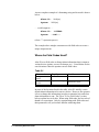
Where Are Field Codes Used? . . . . . . . . . . . . . . . . . . . . . . . . . . . . . . . . . . . . . . . . . . . . . . . . . . . . . . . 5-2
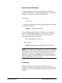
How To Use Field Codes . . . . . . . . . . . . . . . . . . . . . . . . . . . . . . . . . . . . . . . . . . . . . . . . . . . . . . . . . . . 5-3
Handling Alarms
6-1
Viewing Alarms . . . . . . . . . . . . . . . . . . . . . . . . . . . . . . . . . . . . . . . . . . . . . . . . . . . . . . . . . . . . . . . . . . . . . . . . . 6-1
Views . . . . . . . . . . . . . . . . . . . . . . . . . . . . . . . . . . . . . . . . . . . . . . . . . . . . . . . . . . . . . . . . . . . . . . . . . . 6-1
Unconfigured Alarms . . . . . . . . . . . . . . . . . . . . . . . . . . . . . . . . . . . . . . . . . . . . . . . . . . . . . . . . . . . . . . 6-3
Bad Alarms . . . . . . . . . . . . . . . . . . . . . . . . . . . . . . . . . . . . . . . . . . . . . . . . . . . . . . . . . . . . . . . . . . . . . . 6-4
Printing Alarms . . . . . . . . . . . . . . . . . . . . . . . . . . . . . . . . . . . . . . . . . . . . . . . . . . . . . . . . . . . . . . . . . . 6-5
Viewing Alarm States . . . . . . . . . . . . . . . . . . . . . . . . . . . . . . . . . . . . . . . . . . . . . . . . . . . . . . . . . . . . . . . . . . . . . 6-7
Introduction . . . . . . . . . . . . . . . . . . . . . . . . . . . . . . . . . . . . . . . . . . . . . . . . . . . . . . . . . . . . . . . . . . . . . 6-7
Status Colors . . . . . . . . . . . . . . . . . . . . . . . . . . . . . . . . . . . . . . . . . . . . . . . . . . . . . . . . . . . . . . . . . . . . 6-8
Alarm Information Pop-Up . . . . . . . . . . . . . . . . . . . . . . . . . . . . . . . . . . . . . . . . . . . . . . . . . . . . . . . . . 6-8
Actions Menu Commands . . . . . . . . . . . . . . . . . . . . . . . . . . . . . . . . . . . . . . . . . . . . . . . . . . . . . . . . . . . . . . . . . 6-9
Introduction . . . . . . . . . . . . . . . . . . . . . . . . . . . . . . . . . . . . . . . . . . . . . . . . . . . . . . . . . . . . . . . . . . . . . 6-9
Alarms and Alert EL Multi-User . . . . . . . . . . . . . . . . . . . . . . . . . . . . . . . . . . . . . . . . . . . . . . . . . . . . 6-10
Log In . . . . . . . . . . . . . . . . . . . . . . . . . . . . . . . . . . . . . . . . . . . . . . . . . . . . . . . . . . . . . . . . . . . . . . . . . 6-10
Log Out . . . . . . . . . . . . . . . . . . . . . . . . . . . . . . . . . . . . . . . . . . . . . . . . . . . . . . . . . . . . . . . . . . . . . . . 6-11
Silence . . . . . . . . . . . . . . . . . . . . . . . . . . . . . . . . . . . . . . . . . . . . . . . . . . . . . . . . . . . . . . . . . . . . . . . 6-11
Acknowledge . . . . . . . . . . . . . . . . . . . . . . . . . . . . . . . . . . . . . . . . . . . . . . . . . . . . . . . . . . . . . . . . . . . 6-12
Delete . . . . . . . . . . . . . . . . . . . . . . . . . . . . . . . . . . . . . . . . . . . . . . . . . . . . . . . . . . . . . . . . . . . . . . . . . 6-13
View Reporting Status . . . . . . . . . . . . . . . . . . . . . . . . . . . . . . . . . . . . . . . . . . . . . . . . . . . . . . . . . . . . 6-14
SiteScan 2000 . . . . . . . . . . . . . . . . . . . . . . . . . . . . . . . . . . . . . . . . . . . . . . . . . . . . . . . . . . . . . . . . . . . 6-16
Force RTN . . . . . . . . . . . . . . . . . . . . . . . . . . . . . . . . . . . . . . . . . . . . . . . . . . . . . . . . . . . . . . . . . . . . . 6-17
Acknowledge All in View . . . . . . . . . . . . . . . . . . . . . . . . . . . . . . . . . . . . . . . . . . . . . . . . . . . . . . . . . 6-18
Delete All in View . . . . . . . . . . . . . . . . . . . . . . . . . . . . . . . . . . . . . . . . . . . . . . . . . . . . . . . . . . . . . . . 6-18
Alert EL Menu Commands
7-1
How To Use This Chapter . . . . . . . . . . . . . . . . . . . . . . . . . . . . . . . . . . . . . . . . . . . . . . . . . . . . . . . . . . . . . . . . . 7-1
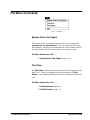
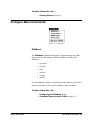
File Menu Commands . . . . . . . . . . . . . . . . . . . . . . . . . . . . . . . . . . . . . . . . . . . . . . . . . . . . . . . . . . . . . . . . . . . . 7-2
System Alarm Text Import . . . . . . . . . . . . . . . . . . . . . . . . . . . . . . . . . . . . . . . . . . . . . . . . . . . . . . . . . . 7-2
Print View . . . . . . . . . . . . . . . . . . . . . . . . . . . . . . . . . . . . . . . . . . . . . . . . . . . . . . . . . . . . . . . . . . . . . . 7-2
Print Setup . . . . . . . . . . . . . . . . . . . . . . . . . . . . . . . . . . . . . . . . . . . . . . . . . . . . . . . . . . . . . . . . . . . . . . 7-3
Exit . . . . . . . . . . . . . . . . . . . . . . . . . . . . . . . . . . . . . . . . . . . . . . . . . . . . . . . . . . . . . . . . . . . . . . . . . . . . 7-3
View Menu Commands . . . . . . . . . . . . . . . . . . . . . . . . . . . . . . . . . . . . . . . . . . . . . . . . . . . . . . . . . . . . . . . . . . . 7-4
Configure Menu Commands . . . . . . . . . . . . . . . . . . . . . . . . . . . . . . . . . . . . . . . . . . . . . . . . . . . . . . . . . . . . . . . . 7-5
Database . . . . . . . . . . . . . . . . . . . . . . . . . . . . . . . . . . . . . . . . . . . . . . . . . . . . . . . . . . . . . . . . . . . . . . . . 7-5
Connections . . . . . . . . . . . . . . . . . . . . . . . . . . . . . . . . . . . . . . . . . . . . . . . . . . . . . . . . . . . . . . . . . . . . . 7-6
Notification . . . . . . . . . . . . . . . . . . . . . . . . . . . . . . . . . . . . . . . . . . . . . . . . . . . . . . . . . . . . . . . . . . . . . . 7-6
Time Zone . . . . . . . . . . . . . . . . . . . . . . . . . . . . . . . . . . . . . . . . . . . . . . . . . . . . . . . . . . . . . . . . . . . . . . 7-6
Receive Station . . . . . . . . . . . . . . . . . . . . . . . . . . . . . . . . . . . . . . . . . . . . . . . . . . . . . . . . . . . . . . . . . . . 7-7
Actions Menu Commands
. . . . . . . . . . . . . . . . . . . . . . . . . . . . . . . . . . . . . . . . . . . . . . . . . . . . . . . . . . . . . . 7-8
Log In . . . . . . . . . . . . . . . . . . . . . . . . . . . . . . . . . . . . . . . . . . . . . . . . . . . . . . . . . . . . . . . . . . . . . . . . . . 7-8
Log Out . . . . . . . . . . . . . . . . . . . . . . . . . . . . . . . . . . . . . . . . . . . . . . . . . . . . . . . . . . . . . . . . . . . . . . . . 7-9
Silence . . . . . . . . . . . . . . . . . . . . . . . . . . . . . . . . . . . . . . . . . . . . . . . . . . . . . . . . . . . . . . . . . . . . . . . . . 7-9
Acknowledge . . . . . . . . . . . . . . . . . . . . . . . . . . . . . . . . . . . . . . . . . . . . . . . . . . . . . . . . . . . . . . . . . . . . 7-9
Delete . . . . . . . . . . . . . . . . . . . . . . . . . . . . . . . . . . . . . . . . . . . . . . . . . . . . . . . . . . . . . . . . . . . . . . . . . 7-10
View Reporting Status . . . . . . . . . . . . . . . . . . . . . . . . . . . . . . . . . . . . . . . . . . . . . . . . . . . . . . . . . . . . 7-10
Alert EL User’s Guide
Contents • 3
SiteScan 2000 . . . . . . . . . . . . . . . . . . . . . . . . . . . . . . . . . . . . . . . . . . . . . . . . . . . . . . . . . . . . . . . . . . . 7-10
Force RTN . . . . . . . . . . . . . . . . . . . . . . . . . . . . . . . . . . . . . . . . . . . . . . . . . . . . . . . . . . . . . . . . . . . . . 7-11
Acknowledge All in View . . . . . . . . . . . . . . . . . . . . . . . . . . . . . . . . . . . . . . . . . . . . . . . . . . . . . . . . . 7-11
Delete All in View . . . . . . . . . . . . . . . . . . . . . . . . . . . . . . . . . . . . . . . . . . . . . . . . . . . . . . . . . . . . . . . 7-11
Help Menu Commands . . . . . . . . . . . . . . . . . . . . . . . . . . . . . . . . . . . . . . . . . . . . . . . . . . . . . . . . . . . . . . . . . . . 7-12
Overview . . . . . . . . . . . . . . . . . . . . . . . . . . . . . . . . . . . . . . . . . . . . . . . . . . . . . . . . . . . . . . . . . . . . . . 7-12
Index . . . . . . . . . . . . . . . . . . . . . . . . . . . . . . . . . . . . . . . . . . . . . . . . . . . . . . . . . . . . . . . . . . . . . . . . . . 7-13
Using Help . . . . . . . . . . . . . . . . . . . . . . . . . . . . . . . . . . . . . . . . . . . . . . . . . . . . . . . . . . . . . . . . . . . . . 7-14
Upgrading to Alert . . . . . . . . . . . . . . . . . . . . . . . . . . . . . . . . . . . . . . . . . . . . . . . . . . . . . . . . . . . . . . . 7-14
About Alert EL . . . . . . . . . . . . . . . . . . . . . . . . . . . . . . . . . . . . . . . . . . . . . . . . . . . . . . . . . . . . . . . . . . 7-15
Maintenance Issues
8-1
Alert EL Multi-User . . . . . . . . . . . . . . . . . . . . . . . . . . . . . . . . . . . . . . . . . . . . . . . . . . . . . . . . . . . . . . . . . . . . . . 8-1
Receiving Stations . . . . . . . . . . . . . . . . . . . . . . . . . . . . . . . . . . . . . . . . . . . . . . . . . . . . . . . . . . . . . . . . 8-3
Connection Configuration . . . . . . . . . . . . . . . . . . . . . . . . . . . . . . . . . . . . . . . . . . . . . . . . . . . . . . . . . . 8-6
Network Router Configuration . . . . . . . . . . . . . . . . . . . . . . . . . . . . . . . . . . . . . . . . . . . . . . . . . . . . . . . 8-8
Ramifications of Using Alert EL Multi-User . . . . . . . . . . . . . . . . . . . . . . . . . . . . . . . . . . . . . . . . . . . . 8-8
Commands That Affect Other Stations . . . . . . . . . . . . . . . . . . . . . . . . . . . . . . . . . . . . . . . . . . . . . . . . 8-9
Database Concerns . . . . . . . . . . . . . . . . . . . . . . . . . . . . . . . . . . . . . . . . . . . . . . . . . . . . . . . . . . . . . . . . . . . . . . 8-10
Introduction . . . . . . . . . . . . . . . . . . . . . . . . . . . . . . . . . . . . . . . . . . . . . . . . . . . . . . . . . . . . . . . . . . . . 8-10
Multiple Databases . . . . . . . . . . . . . . . . . . . . . . . . . . . . . . . . . . . . . . . . . . . . . . . . . . . . . . . . . . . . . . . 8-10
Database Location . . . . . . . . . . . . . . . . . . . . . . . . . . . . . . . . . . . . . . . . . . . . . . . . . . . . . . . . . . . . . . . 8-11
Backing Up the Database . . . . . . . . . . . . . . . . . . . . . . . . . . . . . . . . . . . . . . . . . . . . . . . . . . . . . . . . . . 8-11
Restoring the Database . . . . . . . . . . . . . . . . . . . . . . . . . . . . . . . . . . . . . . . . . . . . . . . . . . . . . . . . . . . . 8-12
Alert Database Utility . . . . . . . . . . . . . . . . . . . . . . . . . . . . . . . . . . . . . . . . . . . . . . . . . . . . . . . . . . . . . 8-12
The alc.ini File . . . . . . . . . . . . . . . . . . . . . . . . . . . . . . . . . . . . . . . . . . . . . . . . . . . . . . . . . . . . . . . . . . . . . . . . 8-16
Introduction . . . . . . . . . . . . . . . . . . . . . . . . . . . . . . . . . . . . . . . . . . . . . . . . . . . . . . . . . . . . . . . . . . . . 8-16
[Alert] Section . . . . . . . . . . . . . . . . . . . . . . . . . . . . . . . . . . . . . . . . . . . . . . . . . . . . . . . . . . . . . . . . . . 8-16
[Logger] Section . . . . . . . . . . . . . . . . . . . . . . . . . . . . . . . . . . . . . . . . . . . . . . . . . . . . . . . . . . . . . . . . . 8-18
Appendix A
9-1
Old-Style Alarms . . . . . . . . . . . . . . . . . . . . . . . . . . . . . . . . . . . . . . . . . . . . . . . . . . . . . . . . . . . . . . . . . . . . . . . . 9-1
Templates . . . . . . . . . . . . . . . . . . . . . . . . . . . . . . . . . . . . . . . . . . . . . . . . . . . . . . . . . . . . . . . . . . . . . . . 9-2
Preconfiguring Old-Style Alarms . . . . . . . . . . . . . . . . . . . . . . . . . . . . . . . . . . . . . . . . . . . . . . . . . . . . . 9-6
Appendix B
10-1
Alert EL Error Messages . . . . . . . . . . . . . . . . . . . . . . . . . . . . . . . . . . . . . . . . . . . . . . . . . . . . . . . . . . . . . . . . . 10-1
Reporting Action Error Messages . . . . . . . . . . . . . . . . . . . . . . . . . . . . . . . . . . . . . . . . . . . . . . . . . . . . . . . . . 10-14
Alphanumeric Pager Error Messages . . . . . . . . . . . . . . . . . . . . . . . . . . . . . . . . . . . . . . . . . . . . . . . . 10-15
ASCII File Write Error Messages . . . . . . . . . . . . . . . . . . . . . . . . . . . . . . . . . . . . . . . . . . . . . . . . . . 10-21
Numeric Pager Error Messages . . . . . . . . . . . . . . . . . . . . . . . . . . . . . . . . . . . . . . . . . . . . . . . . . . . . 10-22
Parallel Printer Error Messages . . . . . . . . . . . . . . . . . . . . . . . . . . . . . . . . . . . . . . . . . . . . . . . . . . . . 10-27
Serial Output Error Messages . . . . . . . . . . . . . . . . . . . . . . . . . . . . . . . . . . . . . . . . . . . . . . . . . . . . . 10-30
Glossary of Terms
11-1
Index
12-1
4 • Contents
Alert EL User’s Guide
1
Introduction to Alert EL
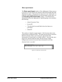
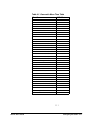
How To Use This Manual
This manual consists of four major sections, organized in the order in
which they should be addressed:
Table 1-1. Alert EL User’s Guide
Section
Part I. Introduction
Part II. Configuration
Part III. Operation
Part IV. Reference
Chapter
Introduction to Alert EL
Configuring the Database
Configuring Reporting Actions
Configuring the Station
Formatting with Field Codes
Handling Alarms
Alert EL Menu Commands
Maintenance Issues
Appendix A - Old-Style Alarms
Appendix B - Error Messages
Glossary
Index
For first time users, it is strongly suggested that you read the
Introduction first. This section provides a general overview of Alert
EL. Next, read the Configuration section, which details how to
configure the database, station, and reporting actions in preparation for
operation. When the station is ready to begin receiving alarms, the
Operation section discusses all of the commands necessary to handle
incoming alarms.
Alert EL User’s Guide
Introduction to Alert EL • 1-1
The Reference section can be used for consultation at any time. It
briefly describes all of the Alert EL menu commands and various
maintenance issues.
This manual assumes that you are familiar with all of Liebert
Corporation software products (such as SiteScan 2000 for Windows and
Eikon) and the Liebert Corporation network topology. It also assumes
that you are familiar with working in the Windows environment.
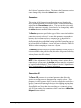
What Is Alert EL?
Alert EL is a comprehensive alarm management software package
which runs in the Windows environment. It is designed to provide
maximum alarm handling flexibility. For instance, alarms can be
assigned "security levels" and can be categorized into Groups. Alert EL
can also perform automated Reporting Actions when an alarm is
received, such as calling a pager or printing alarm information.
Multiple Views
Alert EL can display alarms in one of seven different "views", each
showing a different type of alarm or message. Another Alert EL feature
allows the Main Operator to customize operator access to the system by
assigning individual operators passwords and numeric "security levels"
which are required to use certain commands and to act on alarms.
Unlimited Alarms
When an FB uses the Alert microblock to generate alarms and messages,
the number of alarms that may exist per FB is virtually unlimited.
Multi-User Capability
Alert EL has multi-user capability, where multiple stations may exist on
a Local or Wide Area Network and share a single database. A highperformance database engine allows greater speed, multi-user access
control, and future extendibility during record access. Because the
database is shared, each alarm can have actions performed on it from
1-2 • Introduction to Alert EL
Alert EL User’s Guide
any station. For example, when an alarm is "acknowledged" from one
station, the alarm's change of state is displayed on every multi-user
station. Refer to the "Alert EL Multi-User" section on page 8-1 for more
information about Alert EL’s Multi-User capability.
Minimum Requirements
Minimum Software Requirements
Alert EL Single-User
•
MS-DOS 5.0 or later.
•
Microsoft Windows 3.1 or higher.
•
SiteScan 2000 for Windows V2.6 or later.
•
DCLAN 2.5 or later.
•
GC2 V4.0 module driver or later (if using SiteGate-232
modules).
•
Module driver V4.0 or later (if downloading GFBs
containing Alert microblocks to modules).
Alert EL Multi-User
•
MS-DOS 5.0 or later.
•
Microsoft Windows 3.1 or higher.
•
SiteScan 2000 for Windows V2.6 or later.
•
DCLAN 2.5 or later.
•
GC2 V4.0 module driver or later (if using SiteGate-232
modules).
•
Module driver V4.0 or later (if downloading GFBs
containing Alert microblocks to modules).
•
Network Interface card (see NOTE below).
•
TCP/IP or NET BIOS protocol stack (see NOTE below).
NOTE Contact Liebert Site Applications for configuring Alert EL
Multi-User on a network.
Alert EL User’s Guide
Introduction to Alert EL • 1-3
Minimum Hardware Requirements
•
80486 IBM PC-AT compatible. (Pentium PCI, 75 MHz
recommended)
•
8 megabytes RAM. (16 mb recommended)
•
540 Mb hard drive.
•
Microsoft mouse.
•
101-key keyboard.
•
VGA card with resolution of 640x480 pixels with 256
simultaneous colors under Windows 3.1. Must also have a
Windows 3.1 driver. (VESA local bus recommended)
•
VGA monitor capable of displaying a resolution of 640x480
pixels with 256 simultaneous colors (0.28 maximum dot
pitch).
•
One parallel port, one serial port.
NOTE Non-receiving stations on Alert EL Multi-User do not require a
serial port.
Windows Considerations
In order to install Alert EL, you must have previously installed
Windows 3.1, Windows 95, or Windows 98. If Windows 3.1 is being
used on a 386 computer, Windows must be running in enhanced mode.
Alert EL will run most efficiently with a screen resolution of at least 640
x 480. Higher screen resolutions are also supported.
Due to restrictions placed on memory access by Windows, an excessive
number of alarms in the Main View (greater than 6000) may cause other
Windows applications that are running to fail, and may lead to
corruptions in the Alert database. The exact number of alarms that can
cause this situation varies depending on other applications that may be
running in addition to Alert EL. This problem is a result of memory
access restrictions, and may occur regardless of the amount of memory
added to the workstation. Note that these restrictions apply only to the
number of alarms in the Main View, not the number of alarms in the
Alert database. To avoid this possibility, be sure to regularly backup
and delete closed alarms.
1-4 • Introduction to Alert EL
Alert EL User’s Guide
Installing Alert EL
Install Alert EL on the station(s) by following the instructions below. If
you want to abort the installation process before it is complete, you can
pick the Exit icon on the lower right of the install screen. However, you
must complete the installation process before you can run Alert EL.
Unless otherwise specified, Liebert Corporation software should always
be installed in chronological order. For example, if Alert EL has a date
of 12/15/96 and SiteScan 2000 for Windows has a date of 12/01/96,
SiteScan 2000 for Windows should be installed before Alert EL.
Liebert Corporation software that has the same dates can be installed in
any order. If you are installing Alert EL Multi-User on a network, you
should first install Alert EL on the network server, then perform the
necessary client installations.
To Install Alert EL
1. Ensure that the computer displays the correct time and date.
Insert the Alert EL Install Disk 1 into a floppy drive of your
computer.
2. Make a backup copy of each installation disk.
3. Run Windows.
4. Pick Run from the Program Manager's File menu. If you are
running Windows 95, pick the Start button and then pick
Run. A pop-up dialog box will appear.
5. At the Command Line, enter a:\setup.exe (or whichever
drive the disk is in). Select OK, or press Enter.
6. At this point, the installation program begins. At the
Welcome pop-up, select one of the following:
•
Install to install the Alert EL program files.
•
Quit to exit the installation.
7. If this is a multi-user installation, the Client Install pop-up
appears.
Select No to perform a complete Alert EL installation on this
computer. Select Yes to perform a Client installation on this
computer. If a Client installation is chosen, Alert EL will be
set up to run on this computer from a network drive.
Alert EL User’s Guide
Introduction to Alert EL • 1-5
NOTE A full Alert EL installation must be performed on the network
server before any Client installations can be successfully completed.
8. At the Specify Location for Alert pop-up, enter the directory
to install Alert EL in and pick OK (or, if this is a Client
installation only, entert the complete path for the network
drive and directory where Alert is already installed). To
install Alert EL in the default directory (c:\ss2000), select
OK.
NOTE In order to use Alert EL's SiteScan 2000 commands to display
a SiteScan 2000 for Windows graphic, you must install Alert EL in the
same directory as the SiteScan 2000 for Windows program files. For
more information about Alert EL's SiteScan 2000 command, see the
"SiteScan 2000" section on page 6-16.
9. At this point, the installation program will begin to copy the
program files. When you are directed to do so, remove and
insert the appropriate diskettes and select OK.
10. After the files have been copied, the Which Program Group?
pop-up appears asking you to specify the Windows Program
Group in which the Alert EL programs will appear.
Enter the name of the Program Group you would like Alert
EL to appear in. If this Program Group already contains a
Logger icon, the Logger icon will be deleted. Press Enter or
pick OK to accept the default.
If a previous version of Alert EL already exists on the
computer, the name of the Program Group containing that
version is listed in the Old Program Group Name box.
To delete the old program group, click on the Delete Old
Program Group Name checkbox.
CAUTION The new program group will contain only programs
installed with Alert EL. Any other program items or icons that are
currently in the old program group will not appear in any group if the
old program group is deleted.
11. When the Program Group has been selected, a pop-up
appears indicating the system files that may need to be
updated. To have the setup program make these changes for
1-6 • Introduction to Alert EL
Alert EL User’s Guide
you, select Update. If you don't want any changes to be
made to the files listed, choose Skip.
12. If a previous version of Alert EL is detected on the computer,
the Specify the Database Path for Alert dialog box appears.
Use this dialog box to identify the drive and directory in
which you want to store Alert EL's database.
The path for the existing database appears in the DBPath
box by default. Press Enter or click OK to accept the default
directory, or enter a different drive and directory that the
Alert database will be stored in. When determining your
database path, please consider the following items:
•
It is strongly recommended that you store the database
information in a subdirectory of the main Alert EL
directory (for example, c:\ss2000\alrtdata). If the
database files are stored in the main Alert EL directory,
database archiving and restoration is extremely difficult
because all of the database files are intermingled with the
Alert EL program files.
•
Furthermore, it is strongly recommended that the
database directory only stores Alert database files (i.e.,
two programs should not share the Alert database
directory). If the Alert database files become mixed with
another program's files (for example, Trend Historian's
database files), it's possible that files could be
overwritten or deleted during backups or restorations.
13. When the installation is complete, the Installation Complete
pop-up will be displayed. Click on the Installation
Complete button to exit the installation program.
14. Insert the disk labeled Alert 1.3a Y2K Upgrade in your
computer’s floppy drive.
15. In Windows Explorer or File Manager, double-click the file
ssael13a.exe on the floppy disk. Install this upgrade to the
same directory you chose in step 9.
16. Quit and restart Windows before using Alert EL.
Alert EL User’s Guide
Introduction to Alert EL • 1-7
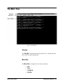
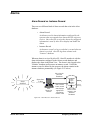
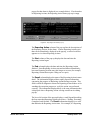
The Alarm Process
The alarm process explained in this section is a general process. It
assumes that all the information necessary to receive an alarm has been
configured.
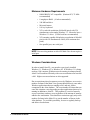
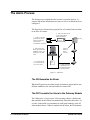
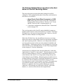
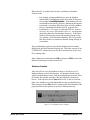
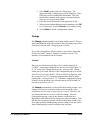
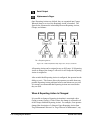
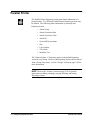
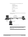
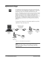
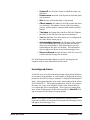
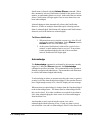
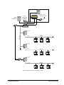
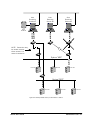
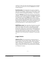
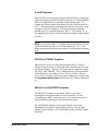
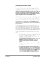
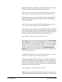
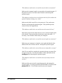
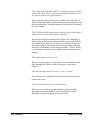
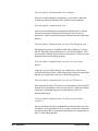
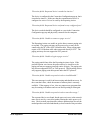
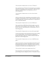
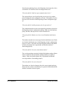
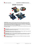
The figure below illustrates the general flow of an alarm from a module
to an Alert EL station.
2. Alert microblock in FB
turns ON and sends
alarm information.
1. An FB in a module
generates an alarm
based on hardware
inputs and/or
user-defined conditions.
Optional
EIA-232
Direct
Connect
5. Alert locates the
alarm type in the Alert
database, logs it, and
displays it in its Main
View.
4. The Alert Server
turns alarm information over to Alert.
DCLAN
ALARM_ID
ACTIVATE
Alert
Server
3. Alarm information
is transmitted from
the gateway module
to the Alert Server.
Figure 1-1: Alarm Flow
The FB Generates An Alarm
When an FB generates an alarm (based on hardware inputs and/or userdefined conditions), the Alert microblock is turned ON.
The FB Transmits the Alarm to the Gateway Module
The CMnet uses a "peer-to-peer" token passing scheme, which means
that a module on the CMnet can transmit only when it has the token. As
a result, each module can communicate with equal authority while all
other modules listen. When its module has the token, the FB transmits
1-8 • Introduction to Alert EL
Alert EL User’s Guide
the alarm to the gateway module through the module driver and it sends
the following alarm information:
•
Time/Date
This is the time and date the FB generated the alarm. This
information can be overwritten with latched data by the Alert
microblock.
•
System ID
This is the three-character name that is assigned in SiteScan
2000 for Windows and Alert EL to an entire local area
network of control modules.
•
Four Digit Address
This is the address of the FB containing the alarm point.
Addresses consist of four numbers: the line number,
gateway module number, module number, and function
block number. An example of a four digit address is
3,5,10,6.
•
Alarm ID
This is a unique code assigned to the alarm. The Alarm ID
is defined in the Alert microblock and in the Alert database.
Alarm ID is discussed further in the "Alarms" section on
page 2-31.
•
Return To Normal
The Return To Normal (RTN) information that is sent to
Alert EL from the module conveys two pieces of
information:
1. Whether the alarm being sent requires an RTN before it
can be closed in Alert EL. This is defined in the Alert
microblock by Liebert Site Applications.
2. Whether an RTN has occurred for the alarm.
When the Alert microblock is configured in Eikon by Liebert
Site Applications, it can be configured to require a Return To
Normal message in order to change from the Active state to
the Inactive state in Alert EL. When an alarm condition no
longer exists, the Alert microblock turns OFF and passes the
RTN message to Alert EL.
•
Five Latched Values
The Alert microblock allows up to five analog or digital
latched values. Latched values are generic data values that
may be sent when the Alert microblock is enabled.
Alert EL User’s Guide
Introduction to Alert EL • 1-9
The Gateway Module Delivers the Alarm to the Alert
Server on the Alert Receiving Station
This step of the process requires that many settings be carefully
configured. These settings and the places where they are discussed in
more detail, are as follows:
•
Alarm Check, Check When Connected, and GCM
Poll settings (discussed in the section INI Configuration
Manager in the SiteScan 2000 for Windows User’s Guide
and the "The alc.ini File" section on page 8-16).
•
Connections configuration (discussed in the "Connections"
section on page 4-2).
The receiving station is the Alert EL station identified in a gateway
module as the location to contact for the delivery of alarms. With Alert
EL Single-User, only one receiving station exists. However, Alert EL
Multi-User allows multiple receiving stations.
With Alert EL Multi-User, the only difference between a receiving
station and a non-receiving station is that receiving stations can launch
and control reporting actions. Otherwise, receiving stations and nonreceiving stations operate in the exact same manner for database and
alarm handling. A station does not have to be designated as a receiving
station in order to view and handle alarms. See the "Receiving Stations"
section on page 8-3 for more information.
An alarm may be configured in the Alert microblock by Liebert Site
Applications as "critical" or "non-critical". When the gateway module
receives an alarm defined as "critical", it immediately delivers any
critical alarms to the Alert EL receiving station, along with any noncritical alarms it may be holding. When the gateway module receives
an alarm defined as "non-critical," it holds the alarm until it is contacted
by a SiteScan 2000 for Windows Workstation acting as an Alert
receiving station or until a critical alarm is received. This contact may
occur when an operator contacts the site using SiteScan 2000 for
Windows or when the Alert Server polls for alarms on a network
connection. RTN messages are delivered to Alert EL in the same
manner (i.e., critical or non-critical) as the original alarm.
1-10 • Introduction to Alert EL
Alert EL User’s Guide
Alert Server Delivers the Alarm to Alert EL
Alert Server is Alert EL's alarm receipt program which resides on a
receiving station. When it is running, Alert Server is visible as a
minimized and unpickable icon on the Windows desktop. When Alert
Server receives an alarm, it determines if the alarm belongs to a System
which Alert Server is configured to monitor. If the alarm belongs to a
System being monitored by Alert Server, Alert Server turns the alarm
over to Alert EL. Once Alert EL receives the alarm, it begins to notify
the operator that an alarm has been received by beeping the PC’s
speaker. If the alarm does not belong to a System being monitored by
Alert Server, the alarm is not retrieved and it is left in the gateway
module.
Alert EL Stores the Alarm Information in the Alert
Database
When Alert EL receives the alarm information from Alert Server, it
checks the Alert database for the alarm type, based on the Alarm ID.
Once Alert EL locates the appropriate alarm type in the database, further
alarm information (previously configured by an operator) will be
extracted.
There are two parts to the Alert database: the instance database and the
records database. The instance database logs all alarms it has ever
received (except for deleted alarms). The records database stores all of
the information necessary to handle alarms.
If Alert EL can locate the Alarm ID in its database, it displays the
information configured for that alarm in the Main View (see Figure 1-7)
and begins to execute any Reporting Actions configured for that alarm.
The alarm is also logged in Alert EL's instance database as an instance
record.
If Alert EL cannot locate the alarm in its records database, it still
displays the alarm in the Main View using the default configuration and
logs the alarm in Alert EL's instance database as an instance record. See
the "Unconfigured Alarms" section on page 6-3 for more information on
how Alert EL handles unconfigured alarms.
Alert EL User’s Guide
Introduction to Alert EL • 1-11
When an Alert microblock generates an RTN message, the same alarm
process is followed as discussed in the steps above. The same
information (System name, address, Alarm ID, etc.) is sent to Alert EL
with an additional field specifying the RTN condition. RTN messages
are delivered to Alert EL in the same manner as the original alarm (i.e.
critical or non-critical). For the purposes of discussion, all future
references to "alarms" also apply to Return To Normal messages.
Alert EL displays the alarm according to the current
view
Because an operator can display different "views" that list different
types of alarms, alarms may be logged by Alert EL but not displayed in
the Main View.
The alarm may go through various states before
being closed in Alert EL
Depending on the requirements configured in the Alert microblock, an
alarm may go through various states before being closed by Alert EL:
•
Active-Unacknowledged
An alarm that has not received a Return To Normal message
(whether it is required or not) and has not been
acknowledged.
•
Active-Acknowledged
An alarm that has not received a Return To Normal message
(whether it is required or not) but has been acknowledged.
•
Inactive-Unacknowledged
An alarm that has received a Return To Normal message but
has not been acknowledged.
•
Inactive-Acknowledged
An alarm that has received a Return To Normal message and
has been acknowledged.
•
Closed
An alarm that has all its requirements fulfilled. These
requirements depend on how the alarm was originally
configured.
1-12 • Introduction to Alert EL
Alert EL User’s Guide
The alarm is "closed" by Alert EL after all
requirements are fulfilled
All alarms must be acknowledged before they can be closed. In
addition, if the alarm was configured in the Alert microblock by Liebert
Site Applications to require an RTN, the alarm will not close until it
receives the RTN.
Closed alarms can be displayed in a view, but as the list of alarms in the
Main View grows, the database also grows and Alert EL's performance
can be slowed. Closed alarms can be deleted from the database, but it is
important to back up the database before doing this. See the "Delete"
section on page 6-13 for information on deleting alarms and the
"Database Concerns" section on page 8-10 for information on backing
up the database.
Preparing to Receive Alarms
This section provides a general overview of how to prepare Alert EL to
receive alarms for a new installation. For complete information about
specific topics, consult the referenced sections.
SiteScan 2000 for Windows and Alert EL
Alert EL can only run when SiteScan 2000 for Windows is installed on
the same station. Alert EL requires that the necessary System files for
the Systems to be monitored by Alert EL be installed on the receiving
station.
SiteScan 2000 for Windows alc.ini Settings
There are several alc.ini settings that must be adjusted in the [Logger]
section and [SVW] section in order for Alert EL to receive alarms
properly. Most of these settings can be changed using the INI
Configuration Manager utility. See the section INI Configuration
Manager in the SiteScan 2000 for Windows User’s Guide and the "The
alc.ini File" section on page 8-16 for complete information on these
settings.
Alert EL User’s Guide
Introduction to Alert EL • 1-13
•
Alarm Check
•
GCM Poll Start
•
GCM Poll End
•
GCMPOLLRTC
•
List
•
File
•
Check When Connected
•
Interval
Make sure that all the Systems that will be monitored by Alert Server are
listed in the [Logger] section of the alc.ini file (List and File settings
in the INI Configuration Manager). This step is extremely important
because if Alert Server receives an alarm that does not belong to a
System being monitored by Alert Server, the alarm is not retrieved and
it is left in the gateway module.
Connection Configuration
In order for Alert EL to receive alarms, gateway modules must be
configured with connection information so that they are able to contact
receiving station(s) with alarms. If the necessary gateway module
configuration has not already been performed, consult the following
Liebert Corporation literature for instructions:
•
DCLAN User Manual
•
SiteGate-ETH User Manual
•
SiteGate-232 User Manual
•
SiteScan 2000 for Windows User's Guide
Make certain that the correct hardware and software requirements are
met (see the "Minimum Requirements" section on page 1-3).
With Alert EL Multi-User, multiple gateway modules do not have to
report alarms to one receiving station. Since the Alert database is
shared, one gateway module can call one receiving station with alarms,
while another gateway module can call a different receiving station with
alarms. The delivered alarm information is made available to all of the
other Alert EL stations. However, one gateway module should not be
set up to call two different receiving stations. If this occurs, the alarm
1-14 • Introduction to Alert EL
Alert EL User’s Guide
information is duplicated in the Alert database (see Figure 8-4 in the
Maintenance Issues chapter).
In addition to configuring the gateway modules, Alert EL must be
configured to monitor the ports that will be receiving alarms and the
receiving station(s) must have the Receive Station setting enabled
(see the "Receive Station Setting" section on page 4-7). If the port
information has not already been configured in SiteScan 2000 for
Windows on the Connection Configuration pop-up, see the
"Connections" section on page 4-2 for information about configuring
connections.
Alert EL uses the same Connection Configuration software provided
with SiteScan 2000 for Windows to store hardware port access
information. This means that you should be careful about making
changes to the Connection Configuration pop-up in Alert EL. After the
ports are configured, connections should not be added or deleted unless
a hardware device is removed or installed on that station. Changing
certain parameters on this screen could prevent SiteScan 2000 for
Windows from finding a device, causing SiteScan 2000 for Windows to
display an error when attempting to connect to an installation.
Configuring the Database
Configuring the Alert database is the most important part of preparing
Alert EL to receive alarms. It is recommended that the database is
configured from a receiving station. See the Configuring the
Database chapter for more information on database configuration.
The information configured in the database is stored in the "records"
portion of the Alert database (see the "Alert EL Stores the Alarm
Information in the Alert Database" section on page 1-11). Configuring
the database involves configuring six different "tables" of information:
•
Operators
The Operator table must be configured with the names,
passwords, and security levels of the people who will be
using Alert EL. The security levels configured in the
Operator table determine the alarms and the commands that
the operator may affect or use. Alert EL's Operator table is
initially created with one operator name, the Main Operator,
with a password of "Alert".
Alert EL User’s Guide
Introduction to Alert EL • 1-15
•
Systems
A System is an entire grouping of control modules that are
identified by a three-character ID. These Systems are the
same Systems in use by SiteScan 2000 for Windows. In
order to receive alarms from Alert Server, the Systems must
be configured in the Alert database because Alert EL's
database is completely isolated from SiteScan 2000 for
Windows’ database for performance reasons.
•
Sites
Sites are single points of contact gateway modules have to
the Workstation. Sites exist within Systems and are
identified by different line numbers in the SiteScan 2000 for
Windows configuration text.
•
Reporting Actions
Reporting Actions perform certain reporting procedures in
Alert EL. Reporting Actions can be configured at any
station, but they can only be executed at a receiving station.
It is not necessary to configure Reporting Actions for alarms,
but using Reporting Actions can cut down on the amount of
manual work an operator must do when handling alarms
(paging personnel, printing alarm information, etc.).
Reporting Actions are discussed in the Configuring
Reporting Actions chapter.
•
Groups
Groups are logical collections of Reporting Actions. An
Alert Reporting Action Group should not be confused with a
SiteScan 2000 for Windows Scheduling Group.
•
Alarms
The Alarms table is a collection of Alarm records that are
stored in the records database. The Alarms table should not
be confused with Alert EL's instance database, where
incoming alarms are logged. When Alert EL receives an
alarm, it uses the Alarms table to "look up" additional alarm
information by the Alarm ID. Alert EL is capable of
receiving alarms that are not configured in the database, but
it is recommended that as many alarms as possible be
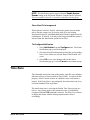
configured in order to best utilize Alert EL's special features.
Configuring the Station
Three special features should be configured which are specific to each
Alert EL station. A brief description of each feature is provided below.
1-16 • Introduction to Alert EL
Alert EL User’s Guide
A more complete discussion is available in the Configuring the
Station chapter.
•
Notification
When Alert EL receives an alarm, it notifies operators in
close proximity to the station by beeping the PC speaker
and/or forcing the Alert EL window to the desktop
foreground. This feature can be enabled or disabled for each
Alert EL station by the operator.
•
Time Zone
Configuring the time zone informs an Alert EL station where
it physically resides in the world. Alert EL stores all dates
and times relative to Greenwich Mean Time (GMT). In
order to do this properly, Alert EL needs to know in which
time zone each station is located.
•
Receive Station
Enabling the Receive Station setting launches Alert
Server, which appears minimized in the Windows work area.
When it is enabled, a check mark appears to the left of
Receive Station and the information is saved in the
alc.ini file. Enable this option if the station is a receiving
station. After Alert Server is launched, Alert EL begins to
receive alarms, so do not enable Receive Station unless
the database, station, and connections have been configured
and Alert EL is ready to receive alarms.
Configuring GFBs With Alert Microblocks
In order to take advantage of Alert EL's alarm handling features, GFBs
should be created by Liebert Site Applications that use the Alert
microblocks, instead of the old Alarm and Message microblocks. GFBs
containing Alert microblocks cannot be downloaded into a module
unless the module driver being used is Version 4.0 (or later).
NOTE Consult Liebert Site Applications for more information
concerning GFB issues.
Alert EL User’s Guide
Introduction to Alert EL • 1-17
Running Alert EL
In order to run properly, Alert Server requires that the DOS program
share.exe be loaded in memory during execution of the
autoexec.bat file. If share.exe is not detected during installation, it
is added to the autoexec.bat file.
NOTE Alert Server must be running in order to receive alarms. If you
want Alert Server to load automatically when Windows is started, copy
Alert EL into the Windows Startup Group as described below. Be sure
that the Receive Station setting in Alert EL is enabled; otherwise,
Alert EL will not be able to receive alarms. Refer to the "Receive
Station Setting" section on page 4-7 for more information.
•
For Windows 3.1, hold down the Ctrl key and drag the Alert
EL icon into the Startup Group with the mouse. The Startup
Group is created when Windows 3.1 is installed. Be sure to
enable Save Settings on Exit from the Windows Program
Manager Options menu before exiting Windows.
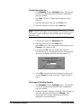
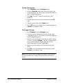
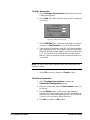
•
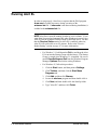
For Windows 95, follow this procedure:
1. Click the Start button, and then point to Settings.
2. Click Taskbar, and then click the Start Menu
Programs tab.
3. Click Add, and then click Browse.
4. Locate the alert.exe program and then double-click it.
5. Click Next, and then double-click the StartUp folder.
6. Type "Alert EL" and then click Finish.
1-18 • Introduction to Alert EL
Alert EL User’s Guide
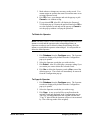
To Start Alert EL From Within Windows
1. Run the Program Manager (it is normally active when
Windows is started.)
2. If the program group is minimized, activate it by doubleclicking on the group icon.
3. Double-click on the Alert EL icon to launch Alert EL. Alert
EL's Main View appears (see the "The Main View" section
on page 1-25).
To Start Alert EL From DOS
CAUTION: Do not use this method from a Windows DOS window,
because Windows is already running. Doing so may lock up your
computer.
1. From the c:\ prompt, type:
win \pathname\alert.exe (where pathname is the entire
pathname where the Alert EL program files are stored)
then press Enter.
OR
From the directory where the Alert EL program files are
stored, type:
win alert.exe
then press Enter.
Alert EL's Main View appears (see the "The Main View"
section on page 1-25).
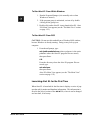
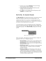
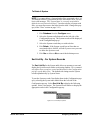
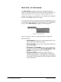
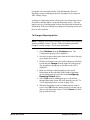
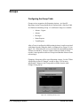
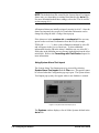
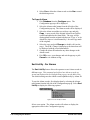
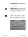
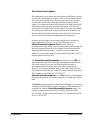
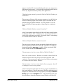
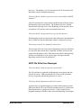
Launching Alert EL for the First Time
When Alert EL is launched for the first time it displays a series of popups that ask for station and database information. This information is
saved in the [Alert] section of the alc.ini file, where it can be changed
at a later date, if necessary.
Alert EL User’s Guide
Introduction to Alert EL • 1-19
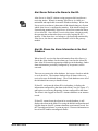
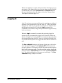
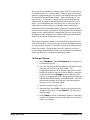
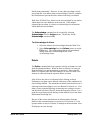
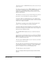
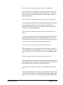
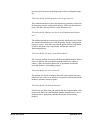
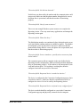
Station Name
Alert EL first displays a pop-up that prompts for a Station Name.
Figure 1-2: Alert EL Station Name pop-up
The Station Name is always displayed in the Title Bar of the Main View.
Enter a Station Name and select OK to continue or Exit to cancel the
station naming process and exit Alert EL. Station Names are used by
Alert EL Multi-User to help track operator log status and Reporting
Actions. They must be unique to each station on the Alert EL MultiUser network.
In addition to storing the Station Name information in the alc.ini file, it
is also stored in the shared database. When Alert EL Multi-User is
launched, Alert EL tries to determine if another station using the same
database has already been registered with the same name. If a duplicate
name is currently in use, Alert EL notifies the operator and asks for a
different name. This process continues until a unique name is found (or
until the operator aborts the process).
If Alert EL Single-User is being used, the Station Name is still required,
but it is less significant.
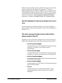
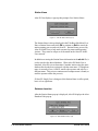
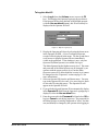
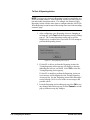
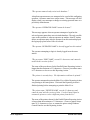
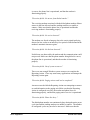
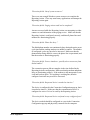
Database Location
After the Station Name pop-up is displayed, Alert EL displays the Alert
Database Path pop-up.
Figure 1-3: Alert Database Path pop-up
1-20 • Introduction to Alert EL
Alert EL User’s Guide
When Alert EL is used for the first time, no database or database
location exists.
•
It is strongly recommended that you store the database
information in a subdirectory of the main Alert EL directory
(for example, c:\ss2000\alrtdata). If the database files are
stored in the main Alert EL directory, database archiving and
restoration is extremely difficult because all of the database
files are intermingled with the Alert EL program files.
•
Furthermore, it is strongly recommended that the database
directory only stores Alert database files (i.e., two programs
should not share the Alert database directory). If the Alert
database files become mixed with another program's files
(for example, Trend Historian's database files), it's possible
that files could be overwritten or deleted during backups or
restorations.
If no prior database path existed, a default database path is initially
displayed in the Alert Database Path pop-up. This name consists of an
"ALRTDATA" subdirectory from the drive and directory where Alert
EL is running from.
Enter a database location and select OK to continue or Exit to cancel the
database location process and exit Alert EL.
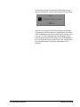
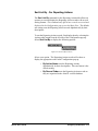
Database Creation
After Alert EL receives the database location, it checks to see if a
database already exists in that location. If a database already exists,
Alert EL loads it and proceeds. If the specified path does not exist, Alert
EL notifies the operator and asks if the path should be created (see
below). If the operator selects Yes and Alert EL is able to create the
path, a new database is created and installed on the specified directory.
If the operator selected No, Alert EL returns to the Alert Database Path
pop-up and allows the operator to specify a different directory.
Figure 1-4: Create Database Path confirmation
Alert EL User’s Guide
Introduction to Alert EL • 1-21
When a new database is created, the System Alarm Text Import pop-up
may appear. This feature allows you to create alarm records for alarm
text that already exists in the sysalarm.txt and xxxalarm.txt files.
For more information about this feature, refer to the "System Alarm
Text Import" section on page 2-35.
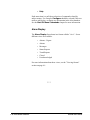
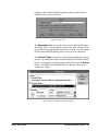
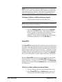
Logging In
Alert EL restricts access to several features by requiring preconfigured
operators to use Operator IDs to log into Alert EL. Unless an operator
is logged into Alert EL, the majority of commands are disabled. Once
the operator logs into Alert EL using the Log In command, the
commands are accessible (as long as the operator has the proper security
level to use them).
When the Log In command is executed, the previously logged in
operator (if any) is automatically logged out of Alert EL and the new
operator is logged in. It is not possible for one station to have more than
one operator logged into Alert EL. However, with Alert EL Multi-User,
it is possible for an operator to be logged into more than one station at a
time.
The Use as default setting on the Operator Login pop-up allows the
same Operator ID to appear in the Operator ID field every time the
pop-up is displayed. This feature is useful if the same operator logs into
the Alert EL station repeatedly. To define a default operator, display the
Operator ID in the Operator ID field and enable the Use as default
box. The default setting takes effect upon successful login. The Use
as default setting is unique to a station.
1-22 • Introduction to Alert EL
Alert EL User’s Guide
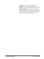
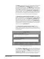
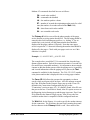
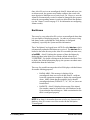
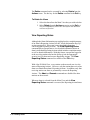
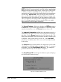
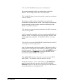
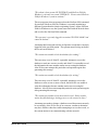
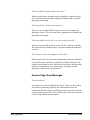
To Log Into Alert EL
1. Select Log In from the Actions menu (or press the F2
key). This displays the Operator Login pop-up (see below).
If an Operator ID has been defined as the default operator
(with the Use as default button), this ID will already be
displayed in the Operator ID field.
Figure 1-5: Operator Login pop-up
2. Display the Operator pull-down by selecting the down arrow
in the Operator ID field. A list of configured Operator
records will be displayed in the menu. Use the up and down
scroll arrows to display Operator IDs not immediately
visible in the pull down. If the database is new, only one
Operator ID (Main Operator) is available for log in.
The Main Operator has the highest security level. The name
and password of the Main Operator can be changed by an
operator with the proper security level, but the Main
Operator can never be deleted and the security level cannot
be changed (see the "Operators" section on page 2-9 for
more information).
3. Select an Operator ID from the pull down menu. You may
type in the Operator ID (last name, first name) but it is faster
to select the ID using the mouse. The Operator ID will
appear in the Operator ID field.
4. If you wish the selected Operator ID to automatically display
in the Operator ID field when the Operator Login pop-up is
displayed, select the Use as default box.
5. Enter the password in the Password field and select OK to
log in or Cancel to exit the log in process. The password for
the Main Operator is initially designated as "Alert", but this
can (and should) be changed by the operator after logging in.
Alert EL User’s Guide
Introduction to Alert EL • 1-23
If an invalid password is entered, the following message
appears and Alert EL returns to the Operator Login pop-up.
Figure 1-6: Incorrect password message
After the correct password has been entered, the Operator
Login pop-up will close and more commands are accessible.
Some commands may be inaccessible if your security level
is too low or if the commands are not appropriate for the
alarm currently selected in the Main View. If the database is
new, no alarms will appear in the Main View, and therefore
the commands that are associated with alarms will be
disabled.
1-24 • Introduction to Alert EL
Alert EL User’s Guide
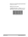
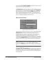
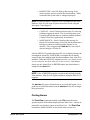
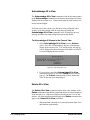
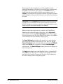
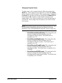
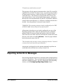
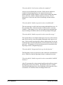
The Main View
Figure 1-7: The Main View
Title Bar
The Title Bar, located at the top of the Main View, contains the name
of the Alert EL station being used.
Menu Bar
The Menu Bar is comprised of five menu selections:
Alert EL User’s Guide
•
File
•
View
•
Configure
•
Actions
Introduction to Alert EL • 1-25
•
Help
Each menu item is a pull-down selection of commands related by
subject matter. For example, Configure should be selected if the user
needs to add, delete, or change any information in the Alert database.
See the Alert EL Menu Commands chapter for more information.
Alarm Display
The Alarm Display lists alarms in a format called a "view". Seven
different views are available:
•
Alarms - Urgent
•
Alarms
•
Messages
•
Status Reports
•
Trend Reports
•
Closed
•
Unacknowledged
For more information about these views, see the "Viewing Alarms"
section on page 6-1.
***
1-26 • Introduction to Alert EL
Alert EL User’s Guide
2
Configuring the Database
Introduction
Configuring the Alert EL records database is probably the most
important part of preparing Alert EL to receive alarms. All the
information necessary to receive and handle alarms is created when the
Alert database is configured.
Throughout this manual, references are made to "instance records" and
"Alarm records". There is a difference between the two. This manual
defines an "instance record" as an actual alarm occurrence which is
logged in the instance database, while an "Alarm record" is alarm
information that the operator configures in Alert EL. When an actual
alarm occurs, Alert EL uses the Alarm record to provide further
information about the alarm. Each Alarm record may be configured
individually, or Alert EL can automatically create Alarm records from
existing sysalarm.txt and xxxalarm.txt files.
This entire chapter is devoted to an explanation of the various database
"tables" that must be configured (Operators, Systems, etc.) and how to
configure them. Because the information for configuring and testing
Reporting Actions is extensive, it is documented separately in the
Configuring Reporting Actions chapter.
If Alert EL Multi-User is being used, keep in mind that any additions,
changes, or deletions to the database records affect other stations.
Alert EL User’s Guide
Configuring the Database • 2-1
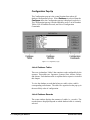
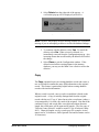
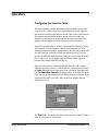
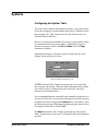
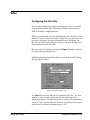
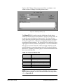
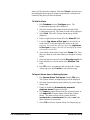
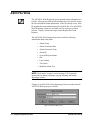
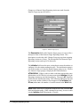
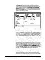
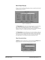
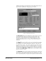
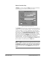
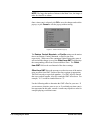
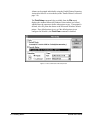
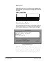
Configuration Pop-Up
The Configuration pop-up is the central location from where all
database configuration occurs. When Database is selected from the
Configure menu, the Configuration pop-up is displayed (see below).
The Configuration pop-up is divided into three areas: List of Database
Tables, List of Database Records, and List of Configuration
Commands.
Figure 2-1: Configuration pop-up
List of Database Tables
There are six database "tables" that contain records configurable by the
operator. These tables are: Operators, Systems, Sites, Actions, Groups,
and Alarms. Each database table is explained in its respective section in
this chapter.
To view the database records that belong to a table, select a table's
corresponding radio button. The tables are organized on the pop-up in
the most likely order of configuration.
List of Database Records
The center window displays the contents of a table (i.e., records). The
records that are displayed depend on which database table is currently
selected.
2-2 • Configuring the Database
Alert EL User’s Guide
These records are accessible by double-clicking on a record or selecting
the record and the Change command. The Add / Change pop-up for
that record will be displayed with the appropriate record information,
and any changes to the record can be made from this pop-up. Records
not immediately visible in the Configuration pop-up can be viewed by
using the right vertical scroll bar.
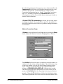
The Sort List By command on the Configuration pop-up displays a
pull-down list with various sort options that the operator may select to
sort and display the database records in the Configuration pop-up. This
only affects the records displayed in the Configuration pop-up, not the
Main View. The available sort options vary depending on what database
table is currently displayed (Operators, Alarms, etc.) and are explained
in their related sections.
List of Configuration Commands
The right side of the pop-up contains all of the commands that act on the
database records. See the following Configuration Commands
section for a description of each of the configuration commands.
Configuration Commands
Add
The Add command allows you to create a new database record (for a
new operator, a new alarm, etc.).
To Add a New Record
1. Select Database from the Configure menu to display the
Configuration pop-up.
2. Display the database table you wish to create a new record
for by selecting the corresponding radio button from the left
side of the pop-up. This will display the table's records in the
center of the Configuration pop-up.
Alert EL User’s Guide
Configuring the Database • 2-3
3. Select Add from the right side of the pop-up. The
appropriate Add / Change pop-up will be displayed. Some
fields may be filled with default information. The field
information contained in the pop-up varies depending on
what type of record is being added.
4. Enter the record information in the appropriate fields.
5. When you are finished adding record information, select OK
to save the record, or select Cancel to exit without saving.
6. Select Close to exit the Configuration window.
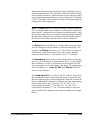
Change
The Change command modifies an existing database record. This is a
feature that should be used with caution because any changes take effect
immediately after the Add / Change pop-up is closed.
If a record is changed that affects an alarm, it also affects alarms that
already exist in the "instance" database as instance records. This
situation is best explained with an example:
Example:
There are several alarms in the Main View with the Alarm ID of
"ALM34". An operator changes the security level of ALM34 from "75"
to "50" in the Add / Change Alarm pop-up. After the Add / Change
Alarm pop-up is closed, but before the Configuration pop-up is closed,
Alert EL receives a new ALM34. The new ALM34 is displayed with
the security level of "50", but at this point the other ALM34 alarms
remain with a security level of "75". When the Configuration pop-up
is finally closed, the Main View refreshes and the ALM34 alarms all
have the security level of "50".
The Change command has a serious effect on Reporting Actions. Any
changes to a Group record or Reporting Action record take effect
immediately after the Add / Change pop-up is closed. Therefore, any
new alarms that Alert EL receives reflect the change. After the
Configuration pop-up is closed, any instance records that have
Reporting Actions affected by the change also reflect the change. Note
that this does not apply to alarms with closed Reporting Actions, but it
does apply to alarms with Reporting Actions waiting to execute, and to
alarms with Reporting Actions currently being executed.
2-4 • Configuring the Database
Alert EL User’s Guide
The reason for having database changes affect Alert EL's operation at
two different times (i.e., when the Add / Change pop-up is closed and
when the Configuration pop-up is closed), is to minimize the steps Alert
EL must perform to handle the changes. Some changes may be very
large in scope. For instance, a change could cause many Reporting
Actions could be added to and deleted from Groups that have active
alarms. It is undesirable to have the Main View re-sort every time a
single Alarm record's security level changed, and it would also be
undesirable to have outstanding alarms regenerate Reporting Actions
before all of the changes were entered. Restricting the effect of database
changes to new alarms until the Configuration pop-up is closed allows
the changes to take immediate effect while delaying the global impact
until all of the desired changes have been made.
This method of database changes is also beneficial to the operation of
Alert EL Multi-User. Once the operator closes the Configuration popup, other Alert EL stations are internally notified of the change(s) and
redraw accordingly. Notifying other Alert EL stations every time a
record changed in the database would cause each station to continually
redraw the Main View or regenerate Reporting Actions.
To Change A Record
1. Select Database from the Configure menu to display the
Configuration pop-up.
2. Select the radio button that corresponds to the database table
containing the record you wish to change. The
Configuration pop-up will display the appropriate records.
3. Double-click on the record you wish to change (or select the
record and then select Change from the right side of the
pop-up). The appropriate Add / Change pop-up is displayed
with the fields filled with the record information. The field
information contained in the pop-up varies depending on
what type of record is being edited.
4. Make any changes to the record.
5. When finished, select OK to close the pop-up and save the
changes to the record, or select Cancel to exit the pop-up
without saving.
6. Select Close to exit the Configuration window. Depending
on what was changed, you may see the Main View refresh to
reflect your changes.
Alert EL User’s Guide
Configuring the Database • 2-5
Delete
The Delete command deletes an existing database record. The Delete
command is similar to the Change command in that it will immediately
affect a record. This could impact instance records. Therefore, this
command should also be used with caution.
When Alert EL receives alarms, it creates links between instance
records and database records. Additionally, when the database is
configured by the operator, links are created between database records.
Because of these links, records cannot be deleted without first removing
the links:
•
Operator record - linked to an instance record when the
operator acknowledges the alarm.
•
System record - linked to a Site record when the Site record
is configured.
•
Site record - linked to an instance record when Alert EL
receives the alarm.
•
Reporting Action record - linked to a Group record when the
Reporting Action is configured.
•
Group record - linked to an Alarm record when the Alarm
record is configured.
•
Alarm record - linked to an instance record when Alert EL
receives the alarm.
To remove a link to an instance record, the associated instance record
must first be deleted from the instance database. Links between
database records can be removed from within Alert EL from the
appropriate Add / Change pop-up. See the applicable sections for more
information.
To Delete a Record
1. Select Database from the Configure menu to display the
Configuration pop-up.
2. Select the radio button that corresponds to the database table
containing the record you wish to delete. The contents of the
Configuration pop-up will change to display the appropriate
records.
3. Select the record you wish to delete from the Configuration
pop-up.
2-6 • Configuring the Database
Alert EL User’s Guide
4. Select Delete from the right side of the pop-up. A
verification pop-up will be displayed (see below).
Figure 2-2: Delete confirmation pop-up
NOTE Alert EL may display an error message instead of a verification
message if you are attempting to delete a record with database linkages.
5. To continue with the deletion, select Yes. To cancel the
deletion, select No. When a record is deleted, it is
immediately removed from the Configuration pop-up. Any
incoming alarms that are affected by the deletion will reflect
the change.
6. Select Close to exit the Configuration window. If the
deleted record affects existing alarms in the instance
database, you may see the Main View refresh to reflect the
deletion.
Copy
The Copy command copies an existing database record and creates a
new record which contains the same field information as the original
record. This feature is particularly helpful when creating database
records with similar information.
When a record is copied, a new record is created that is based on the
original record. A copy is initially distinguished from the original
record with the text "Copy:n" placed next to the record name (where n
is incremented by 1 for each copy made of the original). Note that if the
combined Copy:n and record name exceed the maximum character
length, the record name will be truncated (Example: The first copy of
"Jackson County Schools" would be named "Copy:0 Jackson County
Sch"). Character lengths vary by record types (for example, Action
names can be 30 characters, while Operator first and last names can be
45 characters).
Alert EL User’s Guide
Configuring the Database • 2-7
NOTE When an Alarm record is copied, the new record that is created
is assigned the Alarm ID of "Copy:n" (where n is incremented by 1 for
each copy made of the original) instead of "Copy:n" being appended to
the Alarm ID text.
To Copy a Record
1. Select Database from the Configure menu to display the
Configuration pop-up.
2. Select the radio button that corresponds to the database table
containing the record you wish to copy. The contents of the
Configuration pop-up will change to display the appropriate
records. System or Site records cannot be copied.
3. Select the record you wish to copy from the Configuration
pop-up.
4. Select Copy. Immediately, a copy of the record will be
added to the Configuration pop-up in the "Copy:n" format
described above.
5. At this point, you may use the Change command to make
any changes to the copied record.
6. When finished copying records, select Close to exit the
Configuration pop-up.
Close
The Close command closes the Configuration pop-up. This command
impacts the Main View display if any changes or deletions have been
made to records that affect existing instance records. See the
explanations of the Change and Delete commands for more
information.
The Close command in the Configuration pop-up is not the same as a
Cancel command (found in other pop-ups throughout Alert EL). A
Cancel command will "undo" any changes made in a pop-up. Since
any changes made to database records take effect immediately after the
Add / Change pop-up is closed, the Configuration Close command
cannot "undo" those changes.
2-8 • Configuring the Database
Alert EL User’s Guide
Operators
Configuring the Operator Table
The Operator table contains information about operators who will be
using Alert EL. When an operator acknowledges an alarm, Operator
information is linked to that instance record. This creates a link between
the Operator record and the instance record. Because of this, an
Operator record cannot be deleted until the instance records that the
operator acknowledged are deleted from the instance database.
Alert EL's Operator table is initially created with one Operator record.
This operator is "Main Operator" and the initial password is "Alert".
Although an operator with the appropriate security level may change the
first and last name of the Main Operator and the password, it is not
possible to delete the Main Operator record, nor is it possible to change
the security level. It is strongly suggested that the Main Operator
password be changed after the first log in.
Operator information is added and changed from the Add / Change
Operators pop-up (see below). When Alert EL is used for the first time,
the Add command will be used most often to build the Operator table
(see To Add A New Operator for instructions). With Alert EL MultiUser, any operator information that is added, changed, or deleted in the
Operator table can be viewed by other multi-user stations after the
changes are saved.
Figure 2-3: Add/Change Operator pop-up
The First field contains the first name of the operator. Alert EL allows
up to 20 characters for a first name.
Alert EL User’s Guide
Configuring the Database • 2-9
The Last field contains the last name of the operator. Alert EL allows
up to 25 characters for a last name.
The Password field is used to enter the password of the operator. This
password is used to log into Alert EL. Alert EL allows up to 8 characters
for a password. Passwords are not case sensitive. An operator may
change his/her own password. However, only an operator with a
security level of 100 can view and change passwords. If an operator is
not authorized to view passwords, they are displayed with asterisk
symbols (*).
When a password is added or changed in the Add / Change Operators
pop-up, it must be entered twice − once in the Add / Change Operators
pop-up and once in a Verification pop-up.
The Level field refers to the "security level" of the operator. A security
level is a number that defines a level of access in Alert EL. Security
levels are assigned to operators, commands, and alarms. An operator
must have a security level equal to or greater than a command's security
level in order to perform that command. Additionally, an operator must
have a security level equal to or greater than an alarm's security level in
order to acknowledge that alarm or change the status of that alarm’s
Reporting Actions. If an operator attempts to use a command or
acknowledge an alarm that is above his/her security level, Alert EL
displays an error message.
The highest security level is 100 and the lowest is 1. The Main Operator
ID has a security level of 100, which cannot be changed. Table 4-1 on
the following page lists the security levels for commands. Security
levels for alarms are operator-definable (see the "Alarms" section on
page 2-31 for more information).
2-10 • Configuring the Database
Alert EL User’s Guide
Table 2-1. Command Security Levels Table
Activity
Security
Level
Add Operator
Change Operator
Delete Operator
Copy Operator
Change Passwords
View Passwords
Change Security Level
100
100
100
100
100
100
100
Delete Instance Record
Delete All Instance Records
in Main View
Force RTN
Change Actions
Change Group
95
95
Add Alarm
Change Alarm
Delete Alarm
75
75
75
Copy Alarm
75
95
75
75
Activity
Security
Level
Add System
Change System
Delete System
Add Site
Change Site
Delete Site
Configure as Receive
Station
Configure Connections
Configure Time Zone
75
75
75
75
75
75
75
Configuration Pop-up
Silence
View Reporting Action
Status
Acknowledge Alarm
Acknowledge All
Change Reporting Action
Status
1
1
1
50
25
‡
‡
‡
‡ Operator must have the same security level (or higher) as the corresponding alarm.
Alert EL User’s Guide
Configuring the Database • 2-11
To Add A New Operator
1. Pick Database from the Configure menu. The Operator
records are displayed by default when the Configuration
pop-up is opened.
2. Pick Add. The Add / Change Operator pop-up will be
displayed.
3. Enter the first name of the user in the First field.
4. Enter the last name of the user in the Last field.
NOTE Alert EL will display an error message if you attempt to create
an Operator record with the same first and last name as an existing
Operator record.
5. Enter the password in the Password field.
6. Enter the security level in the Level field.
7. Select OK to save your changes and exit the pop-up or pick
Cancel to exit without saving.
8. If you selected OK, Alert EL displays the Password
Verification pop-up. Reenter the password. The password
characters are displayed with the asterisk symbol ("*").
Figure 2-4: Password Verification pop-up
9. Select OK to save the Operator record and exit the pop-up,
or select Cancel to return to the Add / Change Operator
pop-up.
To Change An Existing Operator
1. Pick Database from the Configure menu. The Operator
records are displayed by default when the Configuration
pop-up is opened.
2. Double-click on the Operator record you wish to change (or
select the Operator record and select Change). This
displays the Add / Change Operator pop-up with the
appropriate record information.
2-12 • Configuring the Database
Alert EL User’s Guide
3. Make whatever changes are necessary to the record. You
cannot assign an operator the same first and last name as an
existing Operator record.
4. Pick OK to save your changes and exit the pop-up or pick
Cancel to exit without saving.
5. If you selected OK, Alert EL will display the Password
Verification pop-up. Reenter the password and select OK to
save the Operator record and exit the pop-up or Cancel to
exit the pop-up without verifying the password.
To Delete An Operator
NOTE Because Alert EL creates a link in the instance database between
instance records and the operators who acknowledged them, an
Operator record may not be deleted without first deleting all of the
instance records that the operator acknowledged. It is not possible to
delete the Main Operator.
1. Pick Database from the Configure menu. The Operator
records are displayed by default when the Configuration
pop-up is opened.
2. Select the Operator record that you wish to delete.
3. Pick Delete. Alert EL will display a message asking if you
are certain you want to delete the selected record.
4. Pick Yes to delete the Operator record or No to cancel the
deletion process. The record will immediately be removed
from the Configuration pop-up.
To Copy An Operator
1. Pick Database from the Configure menu. The Operator
records are displayed by default when the Configuration
pop-up is opened.
2. Select the Operator record that you wish to copy.
3. Pick Copy. A new record will be created based on the
original record and displayed in the Configuration pop-up.
The copy is distinguished from the original with the text
"Copy: n" placed after the last name (where n is incremented
by 1 for each copy made of the original).
Alert EL User’s Guide
Configuring the Database • 2-13
4. Select the copy and pick Change. The Add / Change
Operator pop-up will be displayed.
5. Change the name of the operator and make any other
changes to the record at this time.
6. Pick OK to save the changes and exit the pop-up or pick
Cancel to exit without saving.
Sort List By - For Operator Records
The Sort List By for the Operator table allows an operator to sort and
display the Operator records with several sorting formats. This
command only affects how records are sorted and displayed in the
Configuration pop-up, not the Main View. The default sort setting sorts
the Operator records alphabetically by last name.
To sort the Operator records, first display them in the Configuration
pop-up by selecting the Operators radio button from the left side of the
Configuration pop-up. Select Sort List By to display the following
options.
Figure 2-5: Sort List By for Operators
Select a sort option. The Operator records will redraw to display the
appropriate order in the Configuration pop-up.
2-14 • Configuring the Database
•
By Last Name sorts the Operator records alphabetically by
the operator's last name. This is the default sort setting.
•
By First Name sorts the Operator records alphabetically by
the operator's first name.
•
By Security Level sorts the Operator records numerically
by the security level. Operator records are secondarily
sorted by last name.
•
By Record Order sorts the Operator records as they are
organized in the Alert EL records database. For the most
part, this means that Operator records appear in the order that
they were created. This order may vary if Operator records
are deleted from the Operator table.
Alert EL User’s Guide
Systems
Configuring the System Table
The System table contains information on Systems. A System consists
of an entire grouping of control modules that Alert EL identifies with a
three-character ID. These Systems are the same Systems in use by
SiteScan 2000 for Windows.
Because every Site must be linked to a System, it is not possible to delete
a System that has Sites associated with it. Additionally, because a
System record only consists of the ID and Name field, the Copy
command is disabled.
Additions and changes to System records are made from the Add /
Change System pop-up (see below).
Figure 2-6: Add/Change System pop-up
The ID field in the Add / Change System pop-up is reserved for the
three-character System ID. When an alarm is generated in the module,
one of the key pieces of information sent to Alert EL is the threecharacter System identification.
It is recommended that the System ID not be changed or deleted once it
is created. If Alert EL receives an alarm having a System ID it does not
recognize, the alarm is logged in the alert.err file as a bad alarm. Alert
EL informs the operator of bad alarms by displaying the alarm in Alert
EL using the Alarm ID of "ALERTERR".
The Name field in the Add / Change System pop-up is the System
Name. System Names can be up to 30 characters and can be changed at
any time.
Alert EL User’s Guide
Configuring the Database • 2-15
To Add A New System
1. Select Database from the Configure menu.
2. Select the Systems radio button from the left side of the
Configuration pop-up. The System records will be displayed
in the Configuration pop-up.
3. Pick Add. The Add / Change System pop-up will be
displayed.
4. Enter the three-character System identification in the ID
field.
5. Enter the System Name in the Name field.
6. Select OK to save your changes and exit the pop-up or pick
Cancel to exit without saving.
To Change A System
1. Pick Database from the Configure menu.
2. Select the Systems radio button from the left side of the
Configuration pop-up. The System records will be displayed
in the Configuration pop-up.
3. Double-click on the System record that you wish to change
(or select it and pick Change). The Add / Change System
pop-up will be displayed with the appropriate record
information and the System ID highlighted.
4. Make any desired changes to the System ID or System
Name.
5. Pick OK to save the changes and exit the pop-up or pick
Cancel to exit without saving.
NOTE If the System Name is changed, the change is reflected in the
System field of the Add / Change Site pop-up for the affected Site
records.
2-16 • Configuring the Database
Alert EL User’s Guide
To Delete A System
NOTE You cannot delete a System that has Sites associated with it. If
you attempt to delete a system that has sites associated with it, you will
receive the message, "The 'System Name' is currently associated to
defined sites and cannot be deleted." In order to delete a System with
Sites, you must first remove the links from the Add / Change Site popup (see the "Sites" section on page 2-19).
1. Pick Database from the Configure menu.
2. Select the Systems radio button from the left side of the
Configuration pop-up. The System records will be displayed
in the Configuration pop-up.
3. Select the System record that you wish to delete.
4. Pick Delete. If the System record has no Sites that are
associated with it, Alert EL will ask if you are sure you want
to delete the System record.
5. Pick Yes to delete or No to cancel the deletion process.
Sort List By - For System Records
The Sort List By for the System table allows an operator to sort and
display the System records with several sorting formats. This command
only affects how records are sorted and displayed in the Configuration
pop-up, not the Main View. The default sort setting sorts the system
records alphabetically by System Name.
To sort the System records, first display them in the Configuration popup by selecting the System radio button from the left side of the
Configuration pop-up. Select Sort List By to display the following
options. Select a sort option. The System list will redraw to display the
appropriate order in the Configuration pop-up.
Figure 2-7: Sort List By for Systems
Alert EL User’s Guide
Configuring the Database • 2-17
2-18 • Configuring the Database
•
By Name sorts the System records alphabetically by
System Name. This is the default sort setting.
•
By ID sorts the System records alphabetically by System ID.
•
By Record Order sorts the System records as they are
organized in the Alert EL records database. For the most
part, this means that System records will appear in the order
that they were created. This order may vary if System
records are deleted from the System table.
Alert EL User’s Guide
Sites
Configuring the Site Table
The Site table contains information regarding Sites. Sites exist within
Systems and are identified by different line numbers in the SiteScan
2000 for Windows configuration text.
When the operator adds Site record information to the Alert EL records
database, a link is created (in the Add / Change Site pop-up) between a
previously configured System record and the newly configured Site.
Because every Site must be linked to a System, you must configure your
System table before the Site table.
Because each Site is linked to a System, the Copy command is disabled
to avoid creating accidental links.
Additions and changes to the Site table are made from the Add / Change
Site pop-up (see below).
Figure 2-8: Add/Change Site pop-up
The Line field is used to enter the Line Number of the Site. The Line
Number is used by SiteScan 2000 for Windows and Alert EL for
addressing purposes. Each Site must have its own Line Number within
a System. Since SiteScan 2000 for Windows is limited to 150 Sites per
System, the Line Number should not be over 150.
Alert EL User’s Guide
Configuring the Database • 2-19
The Name field is reserved for the Site Name. When SiteScan 2000 for
Windows was configured with Sites, this information was also created.
Site names may be up to 25 characters. The same Site Name can be
assigned to multiple sites, as long as the Line Numbers are different.
The System field is where a link to a System is made. Each Site must
be linked to the System it is associated with, or Alert EL will not allow
the Site record to be saved. A System can be selected from the pull
down menu.
NOTE A System may also be selected by tabbing down to the System
field (or selecting the pull down arrow) and typing the first letter of the
System. Each time the first letter is typed, Alert EL displays the next
System in the list that begins with that letter.
The Time Zone section of the Add / Change Site pop-up is used to
define the time zone where the site is located. This information is
important because Alert EL needs to know what time an alarm occurred
in relation to the receiving station time. For the continental United
States, the four standard time zones are provided: Eastern, Central,
Mountain, and Pacific.
For other locations, enter the offset from Greenwich Mean Time
(GMT). The Offset from GMT field can only accept whole numbers.
If a GMT offset is entered that is not a whole number, Alert EL rounds
the GMT offset down. For example, "4.9" would be rounded down to
"4". See Table 4-1 on page 4-11 for GMT information.
To Add A New Site
1. Pick Database from the Configure menu.
2. Pick the Sites radio button from the Configuration pop-up.
The Site records will be displayed in the Configuration popup.
3. Pick Add. The Add / Change Site pop-up will be displayed.
4. Enter a line number in the Line field. Line numbers must be
unique within a System.
5. Enter a site name in the Name field.
6. From the System field, select the System that the Site is
associated with.
2-20 • Configuring the Database
Alert EL User’s Guide
7. Select a time zone in the Time Zone field.
8. Select OK to save your changes and exit the pop-up or pick
Cancel to exit without saving.
To Change A Site
NOTE You cannot change the Line Number or associated System of a
Site record if instance records exist that are linked to the Site record.
This applies even if the instance record is in the Closed state.
1. Pick Database from the Configure menu.
2. Pick the Sites radio button from the Configuration pop-up.
The Site records will be displayed.
3. Double-click on the Site record that you wish to change (or
select it and pick Change). The Add / Change Site pop-up
will be displayed with the appropriate record information.
4. Make any desired changes to the record.
5. Pick OK to save your changes and exit the pop-up or pick
Cancel to exit without saving.
To Delete A Site
NOTE You cannot delete a Site record if instance records exist that use
that Site record. To delete a Site record, you must first delete all of the
associated instance records. This applies even if the instance record is
in the Closed state.
1. Pick Database from the Configure menu.
2. Pick the Sites radio button from the Configuration pop-up.
The Site records will be displayed in the Configuration popup.
3. Select the Site record that you wish to delete.
4. Pick Delete. Alert EL will ask if you are sure you want to
delete the Site record.
5. Pick Yes to delete or No to cancel the deletion process.
Alert EL User’s Guide
Configuring the Database • 2-21
Sort List By - For Site Records
The Sort List By command located on the Configuration pop-up
allows an operator to sort Site records using various sort formats. This
command only affects how records are sorted and displayed in the
Configuration pop-up, not the Main View. The default sort setting sorts
the Site records alphabetically by Site Name.
To sort the Site records, first display them in the Configuration pop-up
by selecting the Sites radio button from the left side of the Configuration
pop-up. Select Sort List By to display the following options.
Figure 2-9: Sort List By for Sites
Select a sort option. The Site records will redraw to display the
appropriate order.
2-22 • Configuring the Database
•
By Site Name sorts the Site records alphabetically by Site
Name. This is the default sort setting.
•
By Line Number sorts the Site records numerically by the
Site's Line Number.
•
By System / Line Number sorts the Sites alphabetically
by the associated System ID. Sort List By System / Line
Number also displays the Sites' Line Numbers.
•
By Record Order sorts the Site records as they are
organized in the Alert EL records database. For the most
part, this means that Site records appear in the order that they
were created. This order may vary if Site records are deleted
from the Site table.
Alert EL User’s Guide
Actions
Overview
This section explains Reporting Actions and how to change and test
them in a general manner. For information concerning specific
Reporting Actions, see the following chapter, Configuring
Reporting Actions.
A Reporting Action is an automatic procedure that is launched after an
alarm is received by an Alert EL station. This feature is extremely
useful in reducing manual procedures that are performed when an alarm
is received (for example, paging personnel, sending alarm information
to a printer, etc.).
Only the station which receives an alarm (designated as a "receiving
station" on Alert EL Multi-User) can launch Reporting Actions. See the
"Alert EL Multi-User" section on page 8-1 for more information on
receiving stations.
Reporting Actions are associated with alarms through Groups (see
Figure 2-10 on page 2-24). If Alert EL receives an alarm that has
Reporting Actions, operators have the capability to view the Reporting
Actions' status as they are launched and executed. The operator logged
in at the receiving station that received the alarm has the ability to Abort
or Execute the Reporting Action if he/she has the proper security level.
See the "View Reporting Status" section on page 6-14 for more
information on viewing Reporting Action status.
The following types of Reporting Actions are available:
ASCII File Write
Numeric Pager
Parallel Printer
Alert EL User’s Guide
Configuring the Database • 2-23
Serial Output
Alphanumeric Pager
Once Reporting Actions are defined, they are organized into Groups.
When an alarm is received, the Reporting Action is launched. The
figure below illustrates the relationship between Reporting Actions,
Groups, and Alarms:
Alarm
Record
#2
Alarm
Record
#3
Group A
Group B
Group C
RA
#6
RA
#3
Alarm
Record
#1
RA
#1
RA
#4
Alarm
Record
#4
RA
#7
RA
#4
RA
#6
RA
#1
RA
#3
RA
#7
RA = Reporting Action
Figure 2-10: Relationship Between Reporting Actions, Groups, and Alarms
A Reporting Action can be assigned to any or all Groups. If a Reporting
Action is changed, the change is effective for all Groups the Reporting
Action is assigned to.
After an individual Reporting Action is configured, the operator has the
ability to test it. This feature allows the operator to trouble-shoot any
possible Reporting Action problems before actual alarms are received.
It is strongly recommended that Reporting Actions are tested before
they are used.
When A Reporting Action Is Changed
It is possible to change a Reporting Action that is associated with a
Group (or many Groups). If this is done, the change is reflected in all
of the Groups with that Reporting Action. For example, if an operator
changed the description of a Numeric Pager Reporting Action from
"Page Maintenance Director" to "Page Director of Maintenance", any
2-24 • Configuring the Database
Alert EL User’s Guide
Group that was associated with the "Page Maintenance Director"
Reporting Action would display the new description in its respective
Add / Change Group.
A change to a Reporting Action will also affect any alarms that exist in
the instance database that are using that Reporting Action. This only
applies, however, if the Reporting Actions associated with the alarm are
not finished. If they are finished, any changes to a Reporting Action will
have no effect on them.
To Change A Reporting Action
NOTE Changing a Reporting Action may affect alarms with Reporting
Actions waiting to execute. See the "When A Reporting Action Is
Changed" section on page 2-24 for more information.
1. Select Database from the Configure menu. The
Configuration pop-up will be displayed.
2. Select the Actions radio button from the left side of the popup to display the records.
3. Double-click on the record you wish to change (or select the
record and pick Change from the right side of the pop-up).
The appropriate editing pop-up for that record will be
displayed.
4. Make any changes to the Reporting Action record.
Information on the individual fields within a Reporting
Action editing pop-up is provided in the Configuring
Reporting Actions chapter.
5. Select Test from the editing pop-up to verify that the
changed Reporting Action will work properly (see the "To
Test A Reporting Action" section on page 2-26).
6. When the Reporting Action is working properly with no
errors, select OK from the editing pop-up to exit the pop-up
and save the Reporting Action, or select Cancel to exit the
pop-up without saving.
Alert EL User’s Guide
Configuring the Database • 2-25
To Test A Reporting Action
NOTE It is imperative that each Reporting Action be tested before it is
used in an alarm situation. Some Reporting Actions may take longer to
test and trouble-shoot than others. For example, the Numeric Pager
Reporting Action will take more time to configure than the ASCII File
Write Reporting Action because of the timing issues involved in sending
a numeric page.
1. After configuring a new Reporting Action or changing an
existing one, select Test from the Reporting Action's editing
pop-up. The Testing Reporting Action pop-up will be
displayed (see example below) and Alert EL will attempt to
perform the Reporting Action.
Figure 2-11: Testing Reporting Action pop-up
2. If Alert EL is able to perform the Reporting Action, the
Testing Reporting Action pop-up will display a message
indicating the test was successful. Select OK to close the
Testing Reporting Action pop-up.
If Alert EL is unable to perform the Reporting Action, an
error message will be displayed in the Testing Reporting
Action pop-up. See the "Reporting Action Error Messages"
section on page 10-14 for a list of the error messages and
possible causes.
3. From the Reporting Action editing pop-up, select OK to save
any changes and exit the pop-up, or select Cancel to exit the
pop-up without saving any changes.
2-26 • Configuring the Database
Alert EL User’s Guide
Sort List By - For Reporting Actions
The Sort List By command for the Reporting Action table allows an
operator to sort and display the Reporting Action records with several
sorting formats. This command only affects how records are sorted and
displayed in the Configuration pop-up, not the Main View. The default
sort setting sorts the Reporting Action records alphabetically by their
descriptions.
To sort the Reporting Action records, first display them by selecting the
Actions radio button from the left side of the Configuration pop-up.
Select Sort List By to display the following options.
Figure 2-12: Sort List By for Actions
Select a sort option. The Reporting Action records will redraw to
display the appropriate order in the Configuration pop-up.
Alert EL User’s Guide
•
By Action Name sorts the Reporting Actions
alphabetically by their descriptions. This sort format is the
default setting.
•
By Record Order sorts the Reporting Action records as
they are organized in the Alert EL records database.
Configuring the Database • 2-27
Groups
Configuring the Group Table
Groups exist as organizers for Reporting Actions. An Alert EL
Reporting Action Group should not be confused with a SiteScan 2000
for Windows Scheduling Group. Five different Groups are available:
•
Alarms - Urgent
•
Alarms
•
Messages
•
Status Reports
•
Trend Reports
After a Group is configured with Reporting Actions, it can be associated
with Alarm record(s) when the alarm is configured (see Figure 2-10 on
page 2-24). When Alert EL receives an alarm, the associated Reporting
Actions are launched. Because Alarm records are linked to Group
records, it is not possible to delete a Group record that has Alarm records
referencing it.
Changing a Group may affect active Reporting Actions. See the "When
A Reporting Action Is Changed" section on page 2-24 for more
information. Changes to the Group table are made from the Add /
Change Group pop-up
Figure 2-13: Add/Change Group pop-up
2-28 • Configuring the Database
Alert EL User’s Guide
The Group Name field displays the name of the group. This name
cannot be changed.
The Scheduled Actions section of the Add / Change Group pop-up
is used to display the individual Reporting Actions that are associated
with that Group. Reporting Actions can be added to a Group with the
Add command and can be removed from a Group with the Delete
command (see the "To Assign a Reporting Action to a Group" section
on page 2-29 and the "To Delete a Reporting Action from a Group"
section on page 2-29).
To Change A Group
1. Pick Database from the Configure menu.
2. Pick the Groups radio button from the Configuration pop-up.
The Group records will be displayed in the Configuration
pop-up.
3. Double-click on the Group record to be changed (or select it
and pick Change). The Add / Change Group pop-up will
be displayed with the record information.
4. Make any changes to the record.
5. Select OK to save your changes and exit the Add/Change
Group pop-up, or select Cancel to exit without saving.
To Assign a Reporting Action to a Group
1. From the Add / Change Group pop-up, select Add. This will
display the Add Action pop-up.
2. Double-click on the Reporting Action that you wish to
assign to the Group (or select the Reporting Action and OK).
3. The Reporting Action will now be visible in the Scheduled
Actions section of the Add / Change Group pop-up.
To Delete a Reporting Action from a Group
1. From the Scheduled Actions section of the Add / Change
Group pop-up, select the Reporting Action you want to
delete.
2. Select Delete. Alert EL will immediately delete the
Reporting Action from the Scheduled Actions section
without prompting for verification.
3. Select OK to save the deletion and close the Add / Change
Group pop-up.
Alert EL User’s Guide
Configuring the Database • 2-29
4. If you change your mind about deleting the Reporting
Action, select Cancel to exit the Add / Change Group popup without deleting. The Reporting Action will be restored
to the Scheduled Actions section for that Group.
Sort List By - For Groups
The Sort List By command for the Group table allows an operator to
sort and display the Group records with several sorting formats. This
command only affects how records are sorted and displayed in the
Configuration pop-up, not the Main View. The default sort setting sorts
the Group records alphabetically by Group Name.
To sort the Group records, first display the Group records by selecting
the Groups radio button from the left side of the Configuration pop-up.
Select Sort List By to display the following options.
Figure 2-14: Sort List By for Groups
Select a sort option. The Group records will redraw to display the
appropriate order in the Configuration pop-up.
2-30 • Configuring the Database
•
By Name sorts the Group records alphabetically by Group
Name.
•
By Record Order sorts the Group records as they are
organized in the Alert EL records database.
Alert EL User’s Guide
Alarms
Alarm Record vs. Instance Record
There are two different kinds of alarm records that exist in the Alert
database:
•
Alarm Record
An Alarm record is alarm information configured by the
operator that corresponds to an alarm Alert EL expects to
receive. Once Alert EL receives the alarm, the configured
information is used by Alert EL to display and handle the
alarm.
•
Instance Record
An Instance record is a log record that is created when an
alarm is received. Alert EL logs these alarms in the
"instance" database.
When an alarm is received by Alert EL, Alert EL matches it with the
alarm information configured in the Alarm records database and
displays the alarm in the Main View. The alarm is also logged to the
"instance" database and becomes an instance record. Unless the
instance record is deleted by the operator, the alarm remains in the
instance database permanently (see Figure 2-15 below).
Alert checks
Records
Database
Alarm
ALMID45
ALMID1
ALMID2
ALMID3
Alarm Sent
To Alert
..
.
Records
Database
ALMID45
Alert
Receiving
Station
Alert locates
Alarm record
and displays
appropriate
information
in Main View
Instance
Database
ALMID45
Alarm is also
logged in the
Instance
Database
Figure 2-15: Alarm Record vs. Instance Record
Alert EL User’s Guide
Configuring the Database • 2-31
The Alarm records database is initially created with several alarm
templates. If Alert EL receives an alarm that is not configured in the
records database, it displays the alarm using the format of one of these
templates. See the "Unconfigured Alarms" section on page 6-3 for
more information.
Configuring the Alarm Table
Alarms can be configured individually in the Alarm table, or they can be
imported from an existing sysalarm.txt or xxxalarm.txt file using
the System Alarm Text Import feature (see the "System Alarm Text
Import" section on page 2-35). In either case, when an alarm is
configured it is associated with a Group. A Group is a collection of
Reporting Actions. When a Group is assigned to an alarm and that
alarm is received by Alert EL, the Reporting Actions associated with
that Group are performed (see the "Groups" section on page 2-28 for
more information).
An Alarm record cannot be saved to the database unless it is associated
with a Group. If it is necessary to configure an alarm with no Reporting
Actions, link the alarm to a Group that has no Reporting Actions
associated with it.
2-32 • Configuring the Database
Alert EL User’s Guide
Use the Add / Change Alarm pop-up (see below) to configure a new
Alarm record or to change an existing Alarm record.
Figure 2-16: Add/Change Alarm pop-up
The Alarm ID field is used to enter the global name for the alarm.
Alarm IDs must be unique to the database. Alert EL uses the Alarm ID
to match a received alarm to its Alarm record. The Alarm ID must
exactly match the Alarm ID entered on the Alert microblock in Eikon by
Liebert Site Applications. Otherwise, it is displayed using one of the
unconfigured alarm templates. The Alarm ID can be composed of up to
eight uppercase letters, numbers, and symbols. It is not recommended
that spaces be used in Alarm IDs. When choosing Alarm IDs, avoid
using IDs that have a special meaning in Alert EL (see the table below).
Refer to the "Templates" section on page 9-6 for more information about
these reserved Alarm IDs.
Table 2-2. Reserved Alarm IDs
Alarm ID
A
A1
ALERTERR
DEFAULT
M
STATUS
TREND
Used for
Unconfigured old-style alarm template
Lock alarm
Bad alarm template
Unconfigured Alert alarm template
Unconfigured old-style message template
Status report template
Trend report template
NOTE Alarms with an ID of STATUS or TREND will be treated by
Alert as old-style alarms. For more information about old-style alarms,
refer to Appendix A.
Alert EL User’s Guide
Configuring the Database • 2-33
If the Log alarms of this type box is checked, Alert EL handles
alarms as it normally does (i.e., alarms are displayed in Main View and
logged in the instance database). By default, the Log alarms of this
type box is checked. However, if the Log alarms of this type box
is not checked, Alert EL does not display the alarm or log it to the
instance database. This feature should be used with extreme caution. If
the Log alarms of this type box is not checked, there will be no
record that the alarm was ever received. In addition, if an RTN is
received that is related to the alarm not being logged, the RTN will also
not be logged.
The Log alarms of this type feature may be disabled in situations
where the station is receiving Daily Status Reports or Trends that do not
need to be viewed or logged by Alert EL. If you do not want to log or
display certain DSRs or Trends, it is not a good idea to leave them
unconfigured because Alert EL will log and display them as
unconfigured alarms. Instead, configuring DSRs and Trends and then
disabling the Log alarms of this type box will cause Alert EL to
ignore the DSR or Trend.
The Group field is used to associate an Alarm record with a Group.
The Group may be selected from the pull-down menu with the mouse.
Once an alarm is associated with a Group, any Reporting Actions that
belong to that Group are launched after Alert EL receives the alarm.
NOTE A Group may also be selected by tabbing down to the Group
field (or selecting the pull down arrow) and typing the first letter of the
Group. Each time the first letter is typed, Alert EL displays the next
Group in the list that begins with that letter.
If the alarm being configured does not require any Reporting Actions,
associate the alarm with any Group that has no associated Reporting
Actions. An Alarm record cannot be saved unless it is associated with
a Group.
NOTE Alarms are sorted into different views depending on the group
the alarm is associated with. For example, alarms associated with the
Alarms group appear in the Alarms view; alarms associated with the
Messages group appear in the Messages view, etc.
2-34 • Configuring the Database
Alert EL User’s Guide
The Security Level field assigns a numeric level of access to the
alarm. An operator must have the same security level as an alarm or
higher in order to acknowledge it and to change the status of any of the
alarm's Reporting Actions. If an operator attempts either of these
actions without the proper security level, Alert EL will display an error
message. Security levels can range from 1-100, with "1" being the
lowest and "100" being the highest.
NOTE Security levels are also assigned to operators to control access
to commands. See the "Operators" section on page 2-9 for more
information.
The Multiline Text field is reserved for additional alarm information.
Multiline text is displayed with an alarm in the Main View (and/or sent
as a serial output to a device such as a printer or terminal using
Reporting Actions). This field allows the operator to enter text that can
exceed one line or the operator can use "field codes", which are numeric
representations of referenceable fields (see the Formatting With
Field Codes chapter for information on field codes).
System Alarm Text Import
The System Alarm Text Import option allows you to automatically
create Alarm records based on alarm text located in the sysalarm.txt
and xxxalarm.txt files (where xxx is the three-character System
name). The sysalarm.txt file contains default alarm text and is
installed with SiteScan 2000 for Windows. The xxxalarm.txt file
contains alarm text that has been customized for a particular System.
The sysalarm.txt file is usually located in the
c:\ss2000\emsys\xxx\m68 directory, while the xxxalarm.txt file is
usually located in the c:\ss2000\emsys\xxx directory. Refer to the
SiteScan 2000 for Windows User’s Guide for more information about
directory structure.
Alarm IDs are created in Alert EL by combining a default ID ("A" for
alarms and "M" for messages) with the alarm text numbers in the
sysalarm.txt and xxxalarm.txt files. The alarm text from these files
is used in the Multiline text field in the Alert EL Alarm record. The
alarms are assigned to Groups according to the alarm IDs. Alarm IDs
beginning with A are assigned to the Alarms Group, and alarm IDs
beginning with M are assigned to the Messages Group.
Alert EL User’s Guide
Configuring the Database • 2-35
NOTE The default alarm IDs created by the System Alarm Text Import
feature may vary depending on settings determined in the alc.ini file.
For more information about these settings, refer to the "The alc.ini File"
section on page 8-16.
All imported alarms are initially assigned a security level of 1. Once the
alarms are imported, the security level and other information can be
changed by using the Add / Change Alarm pop-up.
If the alarm text in the sysalarm.txt or xxxalarm.txt files uses any
special codes to reference information from the FB (for example,
"$P$OAW ~~~~~~~"), these codes will not be translated by Alert EL
and will appear in the view as literal text. To show additional
information from the FB in the alarm’s Multiline text, use Alert EL’s
field codes in the Multiline text to reference latched data from the Alert
microblock. Refer to the Formatting with Field Codes chapter for
more information.
Using System Alarm Text Import
The System Alarm Text Import pop-up is accessed by selecting
System Alarm Text Import from the File menu. This option cannot
be selected when the Configuration pop-up is open. The System Alarm
Text Import pop-up may also appear when a new database is created.
Figure 2-17: System Alarm Text Import pop-up
The Systems window displays a list of all the Systems defined in the
alc.ini file.
2-36 • Configuring the Database
Alert EL User’s Guide
The Import button begins the process of creating alarm records for each
entry in the sysalarm.txt and xxxalarm.txt files for the system
selected in the Systems window. The Import All button imports alarms
from all the Systems appearing in the Systems window. Alert EL first
loads the .txt files into memory, then creates the new Alarm records. A
message may appear if either the sysalarm.txt or xxxalarm.txt files
could not be found. If the System(s) selected in the Systems window
have not already been configured in the Alert database, Alert EL will
also create System records with the description "Unconfigured."
The Automatically overwrite duplicate alarms? option, when
enabled, will automatically overwrite the text of an existing configured
alarm with the alarm text from the sysalarm.txt or xxxalarm.txt files
if the alarm IDs are the same. For example, if the alarm ID M15 has
already been configured in the Alert database and the sysalarm.txt file
for the System being imported contains an entry for M15, then Alert EL
will automatically overwrite the existing Multiline text for alarm M15
with the text from the sysalarm.txt file.
If the Automatically overwrite duplicate alarms? option is
disabled, Alert EL will pause when an alarm text number matches an
existing alarm ID and allow the operator to determine whether or not to
overwrite the text.
Figure 2-18: Duplicate Alarm ID Found pop-up
Choose Replace or Replace All to replace the existing Multiline text
with the imported text, Skip or Skip All to keep the existing Multiline
text and ignore the imported text, or Abort to cancel the import process.
If Replace All or Skip All is chosen, this dialog box will not reappear
if additional duplicate alarms are found, and subsequent duplicate
Alert EL User’s Guide
Configuring the Database • 2-37
alarms will be replaced or skipped. Note that if Abort is chosen at any
time during the import process, alarm records that have already been
created by this process will not be deleted.
To Add An Alarm
1. Pick Database from the Configure menu. The
Configuration pop-up will be displayed.
2. Select the Alarms radio button from the left side of the
Configuration pop-up. The Alarm records will be displayed.
3. Select Add. The Add / Change Alarm pop-up will be
displayed.
4. Enter an eight-character Alarm ID in the Alarm ID field.
5. Leave the Log alarms of this type box checked if you
wish Alert EL to log and display the alarms as they are
received. Be aware that when you leave the Log alarms
of this type box empty, Alert EL will not display the alarm
or keep any record of it!
6. Associate the alarm with a Group in the Group field. Note
that you cannot save the alarm unless you designate a Group
Name.
7. Select the alarm's security level in the Security Level field.
8. Enter Multiline text for the alarm in the Multiline Text
field.
9. Pick OK to save your changes and exit the Add / Change
Alarm pop-up or pick Cancel to exit without saving.
To Import Alarms from an Existing System
1. Pick System Alarm Text Import from the File menu.
The System Alarm Text Import pop-up will be displayed.
2. Select the System in the Systems window you want to import
alarms from.
3. Enable or disable the Automatically overwrite
duplicate alarms? option as desired.
4. Pick Import to import alarms from the selected System, or
pick Import All to import alarms from all the Systems
shown. The alarm records will be created from the
sysalarm.txt and xxxalarm.txt files (where xxx is the
three-character System name).
5. Select OK to close the System Alarm Text Import pop-up.
2-38 • Configuring the Database
Alert EL User’s Guide
6. Follow the steps in the "To Change An Alarm" section below
to change security levels or other information for the new
alarm records as necessary.
To Change An Alarm
NOTE You cannot change the Alarm ID of an Alarm record with
existing instance records without first deleting all of the instance records
that use that Alarm ID. This applies even if the instance record is in the
Closed state.
1. Pick Database from the Configure menu. The
Configuration pop-up will be displayed.
2. Select the Alarms radio button from the left side of the
Configuration pop-up. The Alarm records will be displayed.
3. Select the Alarm record to change and pick Change or
double-click on the Alarm record. The Add/Change Alarm
pop-up will appear with the appropriate record information.
4. Make any desired changes to the fields.
5. Pick OK to save your changes and exit the pop-up or pick
Cancel to exit without saving.
To Delete An Alarm
NOTE You cannot delete an Alarm record with existing instance
records without first deleting all of the associated instance records. This
applies even if the instance record is in the Closed state.
1. Pick Database from the Configure menu. The
Configuration pop-up will be displayed.
2. Select the Alarms radio button from the left side of the
Configuration pop-up. The Alarm records will be displayed.
3. Select the Alarm record that you wish to delete and pick
Delete. If the Alarm record has no associated instance
records, Alert EL will display a message asking you if you
are sure you wish to delete the alarm.
If the Alarm record does have associated instance records,
Alert EL will display an error message.
Alert EL User’s Guide
Configuring the Database • 2-39
4. Select Yes to delete the Alarm record or select No to cancel
the deletion process.
To Copy An Alarm
1. Pick Database from the Configure menu. The
Configuration pop-up will be displayed.
2. Select the Alarms radio button from the left side of the
Configuration pop-up. The Alarm records will be displayed.
3. Select the Alarm record that you wish to copy and pick
Copy. A new record of the original Alarm record will be
created and added to the Alarm table. The copy will be
distinguished from the original with the text "Copy: n" as its
Alarm ID (where n is incremented by 1 for each copy made
of the original).
4. Select the copy and pick Change (or double-click on the
copy). The Add / Change Alarm pop-up for that alarm will
be displayed with the record information.
5. Change the Alarm ID and make any other changes to the
Alarm record.
6. Pick OK to save your changes and exit the pop-up or pick
Cancel to exit without saving.
Sort List By - For Alarms
The Sort List By feature allows the operator to sort Alarm records in
different ways. This command only affects how Alarm records are
sorted and displayed in the Configuration pop-up, not the Main View.
The default setting sorts the Alarm records alphabetically by Alarm ID.
To sort the Alarm records, first display them by selecting the Alarms
radio button from the left side of the Configuration pop-up. Select Sort
List By to display the following options:
Figure 2-19: Sort List By for Alarms
Select a sort option. The Alarm records will redraw to display the
appropriate order in the Configuration pop-up.
2-40 • Configuring the Database
Alert EL User’s Guide
•
Sort List By ID sorts the Alarm records alphabetically by
Alarm ID. This is the default sort setting.
•
Sort List By Text sorts the Alarm records alphabetically
by the Multiline Text.
•
Sort List By Security Level sorts the Alarm records
numerically by the assigned security levels.
•
Sort List By Group Order sorts the Alarm records
alphabetically by their associated Groups.
•
Sort List By Record Order sorts the Alarm records as
they are organized in the Alert EL records database. For the
most part, this means that Alarm records appear in the order
that they were created. This order may vary if Alarm records
are deleted from the Alarm table.
***
Alert EL User’s Guide
Configuring the Database • 2-41
2-42 • Configuring the Database
Alert EL User’s Guide
3
Configuring Reporting
Actions
Introduction
This chapter explains each Reporting Action in the order that they are
listed in the Add Action pop-up (see below). For information on adding,
changing, deleting, copying, and testing Reporting Actions, see the
"Actions" section on page 2-23.
ASCII File Write
Numeric Pager
Parallel Printer
Serial Output
Alphanumeric Pager
Alert EL User’s Guide
Configuring Reporting Actions • 3-1
ASCII File Write
The ASCII File Write Reporting Action appends alarm information to a
text file. If the operator defines a file that does not exist, Alert EL creates
the file and adds the alarm information. If the file already exists, Alert
EL appends the alarm information to the end of the file. Five ASCII File
Write Reporting Actions are available, one for each type of alarm
(Alarms - Urgent, Alarms, Messages, Status Reports and Trend
Reports).
The ASCII File Write Reporting Action records the following
information about each alarm:
•
Alarm Group
•
Alarm Generation Date
•
Alarm Generation Time
•
Alarm ID
•
System ID/System name
•
Site
•
Line Address
•
Tab Labels
•
Multiline Alarm Text
NOTE Refer to the "Actions" section on page 2-23 for general
instructions on adding, changing, copying, deleting, and testing
Reporting Actions.
Changes to an ASCII File Write Reporting Action are made from the
ASCII File Write pop-up (see below).
Figure 3-1: ASCII File Write pop-up
3-2 • Configuring Reporting Actions
Alert EL User’s Guide
The Description field on the ASCII File Write pop-up is reserved for
a description of the ASCII File Write Reporting Action. This
description is displayed in the Add / Change Group pop-up when
assigning configured Reporting Actions to a Group. The description can
be up to 30 characters.
The File name field is used to enter the entire path and file name (for
example, c:\alarms\heatalms.txt). A default file name is
automatically entered for each ASCII File Write Reporting Action. This
file is written to the directory in which the Alert EL programs are stored.
If the operator defines a file that does not exist, Alert EL creates the file
and adds the alarm information. If the file already exists, Alert EL
appends the alarm information to the end of the file. Up to 80 characters
can be entered for a path name. Use the Browse button to select a file
from the disk.
Numeric Pager
The Numeric Pager Reporting Action pages personnel by sending
numeric messages to personal pagers through the use of a third-party
service (definable and subscribed to by the operator). Communication
with the third party pager service is through the use of Hayes compatible
modems. This Reporting Action only supports Hayes compatible
modems. The numeric message may consist of numeric text entered by
the operator and/or the Alarm ID. Two different Numeric Pager
Reporting Actions may be defined.
From the Numeric Pager pop-up, the operator can define how many
times to attempt to connect to the pager service. The operator can also
define a secondary number to call in case the connection to the first
number is unsuccessful. The entire cycle of calling can be repeated for
as many times as the operator defines, or until a successful page is
completed.
NOTE Refer to the "Actions" section on page 2-23 for general
instructions on adding, changing, copying, deleting, and testing
Reporting Actions.
Alert EL User’s Guide
Configuring Reporting Actions • 3-3
Changes to a Numeric Pager Reporting Action are made from the
Numeric Pager pop-up (see below).
Figure 3-2: Numeric Pager pop-up
The Description field on the Numeric Pager pop-up is reserved for a
descriptive name of the Numeric Pager Reporting Action. This
description is used in the Add / Change Group pop-up when assigning
Reporting Actions to a Group. The description of the Numeric Pager
Reporting Action can be up to 30 characters.
The Initialize field is used to enter a string that is sent to the modem to
configure it for the station sending the page. The initialization string is
sent to the modem each time the numeric pager action occurs. When a
new Numeric Pager pop-up is displayed, this field defaults to
ATQ0V0E0L0. If these codes (or other codes that represent the same
information; see NOTE below) are not present in the Initialize field, the
Reporting Action may not function properly. The prefix AT should be
used before the initialization string. The following additional code will
be sent to the modem whether or not it appears in the Initialize field:
S7=xx (where xx = the number of seconds entered in the Wait field).
NOTE Some older Hayes-compatible modems need the command X4
in the initialization string. If this command is necessary, be sure to enter
it in the Initialize field following the AT prefix.
3-4 • Configuring Reporting Actions
Alert EL User’s Guide
Modem AT commands described here are as follows:
Q0 = result codes enabled
E0 = command echo disabled
L0 = low modem speaker volume
S7 = number of seconds the originating modem waits for a dial
tone (the number of seconds entered in the Wait field)
V0 = short form result codes enabled
X4 = use extended result codes
The Primary # field is reserved for the phone number of the pager
service that the receiving station should call. The full string should be
entered in this field, including any prefixes (i.e., dialing "9" for an
outside line), wait periods, and the phone number that should be
displayed in the pager window (if desired). Note that some pager
services require the "#" character following the number that should be
displayed by the pager. Check with your pager service to see if this
character is required.
Example: 9, 1-614-555-3423,,,,,614-555-1212
The example above would dial "9" for an outside line, then the longdistance phone number. Each of the commas represents a 2-second wait
(for most Hayes compatible modems). It is important to insert enough
commas so that the modem pauses while the paging service is speaking
and it sends information when the paging service pauses (the Test
command is available for this function). The "614-555-1212" number
is the phone number that is displayed in the receiving pager window.
The Conn. ID field allows the operator the opportunity to choose
exactly which serial port to dial out from. Alert EL attempts to match
the Conn. ID defined in the Numeric Pager pop-up with a Conn. ID
defined in the Connections Configuration pop-up (see the
"Connections" section on page 4-2). If a match is found, Alert EL uses
that port to dial out. If no match is found, Alert EL reports an error on
the Reporting Action Status pop-up and the page is not sent. If no Conn.
ID is defined in the Numeric Pager pop-up, Alert EL uses the first
available modem that is compatible with the configured baud rate.
The Wait field for the Primary # is used to specify the modem timeout
for the connection. The Wait time does not begin counting down until
the last character in the Primary # field is sent. Since much of the
Alert EL User’s Guide
Configuring Reporting Actions • 3-5
information communicated by the Numeric Pager Reporting Action is
included in the Primary # field, a Wait time of between 5 and 10 seconds
may be all that is necessary. Additional time may be required if a thirdparty communications port redirection utility is being used. The default
is "0:05" (5 seconds). The Wait time may need to be adjusted during the
testing phase of the configuration.
NOTE The Wait field uses a "number scrolling" method to define the
time. To change a time, select a number by clicking on it with the left
mouse button. A horizontal bar will appear beneath the number. Hold
the left mouse button down to scroll forward through numbers and hold
the right mouse button down to scroll backwards through the numbers.
Release the mouse button when the desired number is displayed.
The Retries field for the Primary # is used to define how many times
Alert EL attempts to retry the Primary # if the first attempt fails. For
example, if the Retries field is set to "2", Alert EL tries to connect to
the Primary # a total of three times before it proceeds to attempt to
connect to the Secondary #. This number is set to "2" by default.
The Secondary # field is used to enter the phone number of the pager
service to call if the Primary # connection has failed. It is not required
that a Secondary # is used. If a Secondary # is not defined, Alert EL
does not attempt to use it if the Primary # has failed. The configuration
for the Secondary # (i.e., Conn. ID, Wait field, Retries field) is the
same as for the Primary #.
If the Send alarm ID box is checked, Alert EL sends the Alarm ID of
the alarm that the Numeric Pager Reporting Action is associated with.
Because a numeric pager is used to transmit the Alarm ID, an Alarm ID
that uses alphanumeric characters is displayed using the corresponding
numbers from a phone pad: The letters "A", "B", and "C" are
represented by the number "2"; the letters "D", "E", and "F" are
represented by the number "3", etc. If a phone number is sent to the
pager, the Alarm ID is displayed after the phone number (see example
below).
3-6 • Configuring Reporting Actions
Alert EL User’s Guide
Example:
"614-555-1212326633"
("326633" represents the Alarm ID "FANOFF")
The Discontinue after _____ failed cycles field is used to define
how many times Alert EL should try the entire calling cycle (i.e.
beginning with the Primary # and ending with the Secondary #).
Example:
If the Numeric Pager Reporting Action is configured to . . .
•
Retry the Primary # twice.
•
Retry the Secondary # four times.
•
Try the entire cycle three times.
. . . the end result would be that Alert EL would attempt to . . .
•
Call the Primary # a total of three times.
•
Call the Secondary # a total of five times.
•
Try the entire cycle three times.
If after all cycles were executed and no connection was made, Alert EL
would display an error message in the Reporting Action Status pop-up
and the Reporting Action would fail.
Alert EL User’s Guide
Configuring Reporting Actions • 3-7
Parallel Printer
The Parallel Printer Reporting Action prints alarm information to a
parallel printer. Two different Parallel Printer Reporting Actions may
be defined. The following alarm information is printed by this
Reporting Action:
•
Alarm Group
•
Alarm Generation Date
•
Alarm Generation Time
•
Alarm ID
•
System ID/System name
•
Site
•
Line Address
•
Tab Labels
•
Multiline Text
The "Send to Printer -1" Reporting Action is the default Reporting
Action in every Group. However, this Reporting Action can be removed
from a Group if necessary. See the "Groups" section on page 2-28 for
more information.
NOTE Refer to the "Actions" section on page 2-23 for general
instructions on adding, changing, copying, deleting, and testing
Reporting Actions.
3-8 • Configuring Reporting Actions
Alert EL User’s Guide
Changes to the Parallel Printer Reporting Action are made from the
Parallel Printer pop-up (see below).
Figure 3-3: Printer pop-up
The Description field is reserved for the name of the Parallel Printer
Reporting Action. This description is used in the Add / Change Group
pop-up when assigning Reporting Actions to a Group. The description
of the Parallel Printer Reporting Action can be up to 30 characters.
The Current Printer field indicates what printer the Reporting Action
prints to. By default, this field contains the Microsoft Windows default
printer. To change the designated printer in this field, select the Printer
button. This displays the standard Microsoft Windows Print Setup
window (see below).
Figure 3-4: Microsoft Windows 3.x Print Setup window
Alert EL User’s Guide
Configuring Reporting Actions • 3-9
The Current font field on the Parallel Printer pop-up allows the
operator to select the font to use when printing the alarm information.
The font can only be changed if the Automatic form feed after
printing option is selected. To change the font from the default font
setting, select the Font button. This displays the standard Microsoft
Windows Font window (see below).
Figure 3-5: Microsoft Windows 3.x Font window
If the Automatic form feed after printing box is selected, Alert EL
formats the text using the font selected and sends the alarm information
to the printer. After all of the information is sent, the Reporting Action
sends a form feed command to the printer, and the last page printed is
ejected. The next alarm information (or user file) starts on a new page.
If the Automatic form feed after printing box is disabled, Alert EL
sends the alarm information to the printer, but does not issue a form feed
command after all the information has been sent. The next alarm
information (or user file) is printed immediately after the previous one
on the same page. If the alarm information is being sent to a Laserjet
printer, this setting would require the operator to physically press the
"Form Feed" button on the printer in order to eject the last page from the
printer. Deselecting the Automatic form feed after printing box
also disables the Font command, which causes this Reporting Action to
print alarm information in the designated printer's default font.
If Automatic form feed after printing is disabled, information is
sent directly from the receiving station to the printer, bypassing the
Windows print spooler. Therefore, some less advanced dot matrix
printers (such as the Okidata Microline 182) may not be able to handle
3-10 • Configuring Reporting Actions
Alert EL User’s Guide
the volume of printing output sent by Alert. When this occurs, the
results of the Reporting Actions may be unpredictable. To avoid this
problem, use a more advanced printer (such as the Okdiata Microline
321).
NOTE If Windows 95 or Windows NT is being used and the Parallel
Printer Reporting Action is configured to print to a shared network
printer with Automatic form feed after printing disabled, the
printer must be captured to a port before printing. To do this under
Windows 95, edit the Properties of the desired printer and pick the
Capture Printer Port option to select a port. To do this under
Windows NT, type the following command at a DOS prompt: net use
port printername /P:Y (where port is the name of the desired port
and printername is the name of the desired network printer). Then,
edit the Properties of the printer in Windows NT and assign it to the
corresponding port. To release the captured port in Windows NT, enter
the following command at a DOS prompt: net use port /D (where
port is the name of the desired port).
Serial Output
The Serial Output Reporting Action sends alarm information to a Video
Display Terminal (VDT). The terminal can be directly connected to the
receiving station, or it can be accessed by a modem-to-modem
connection. The alarm information is sent to the VDT and displayed on
the screen. If previous alarm information has been sent, the new
information is displayed starting at the next available line on the screen.
The alarm information can also be sent by a modem-to-modem
connection to a remote serial printer. This Reporting Action only
supports Hayes compatible modems.
Three Serial Output Reporting Actions are available:
Alert EL User’s Guide
•
Send to Serial Output
•
Relay Port On - This Reporting Action is assigned by default
to the Alarms and Alarms - Urgent Groups, and is executed
when an alarm is received.
•
Relay Port Off - This Reporting Action is assigned by default
to the Alarms and Alarms - Urgent Groups, and is executed
when an alarm is acknowledged.
Configuring Reporting Actions • 3-11
The following information is sent by this Reporting Action:
•
Alarm Group
•
Alarm Generation Date
•
Alarm Generation Time
•
Alarm ID
•
System ID/System name
•
Site
•
Line Address
•
Tab Labels
•
Multiline Text
See Figure 3-6 below for an illustration of how a serial output Reporting
Action might be set up.
Serial Output
sent via modems
to Laptop VDT window
Alert
Receiving
Station
Direct Connect
to a VDT
Figure 3-6: Possible Serial Output Configuration
NOTE Refer to the "Actions" section on page 2-23 for general
instructions on adding, changing, copying, deleting, and testing
Reporting Actions.
3-12 • Configuring Reporting Actions
Alert EL User’s Guide
Serial Output Pop-up
Changes to the Serial Output Reporting Action are made from the Serial
Output pop-up (see below).
Figure 3-7: Serial Output pop-up
The Description field of the Serial Output pop-up is reserved for the
name of the Serial Output Reporting Action. This description is
displayed in the Add / Change Group pop-up when assigning Reporting
Actions to a Group. This field can be up to 30 characters.
The Connections section of the pop-up is used to configure what type
of connection the receiving station uses to send the alarm information.
The operator needs to indicate if the VDT is directly connected to the
receiving station or if a modem-to-modem connection is used.
Direct Connection Setup
If Direct (for direct connection) is selected, picking the Setup button
displays the Direct Connection Setup pop-up (see below).
Figure 3-8: Direct Connection Setup pop-up
Alert EL User’s Guide
Configuring Reporting Actions • 3-13
From the Direct Connection Setup pop-up, enter a Connection ID in the
Connection ID field if the receiving station should search for a port
with that Connection ID. (Connection IDs are configured in the
Connection Configuration pop-up. See the "Connections" section on
page 4-2.) If nothing is entered in the Connection ID field, the
receiving station uses the first available direct connect port in order to
send the alarm information.
If Enable RTS/CTS handshaking is selected, the receiving station
uses Request to Send / Clear to Send flow control for data transfer. It
may help to enable this option if there are problems sending information
to the terminal.
Modem Connection Setup
If Modem is selected from the Serial Output pop-up, picking the Setup
button displays the Modem Connection Setup pop-up (see below).
Figure 3-9: Modem Connection Setup
The Initialize field is used to enter a string that is sent to the modem to
configure it for the station sending the output. The initialization string
is sent to the modem each time the Serial Output Reporting Action
occurs. When a new Serial Output pop-up is displayed, this field
defaults to ATQ0V0E0L0S2=43S12=50. If these codes (or other
codes that represent the same information; see NOTE below) are not
present in the Initialize field, the Reporting Action may not function
properly. The prefix AT should be used before the initialization string.
The following additional code will be sent to the modem whether or not
3-14 • Configuring Reporting Actions
Alert EL User’s Guide
it appears in the Initialize field: S7=xx (where xx = the number of
seconds entered in the Wait field).
NOTE Some older Hayes-compatible modems need the command X4
in the initialization string. If this command is necessary, be sure to enter
it in the Initialize field following the AT prefix.
Modem AT commands described here are as follows:
Q0 = result codes enabled
E0 = command echo disabled
L0 = low modem speaker volume
S2 = escape code character (43 is the "+" character − modem
default)
S7 = number of seconds the originating modem waits for a dial
tone (the number of seconds entered in the Wait field)
S12 = escape code guard time (50 x 20 milliseconds = 1 second
−modem default)
V0 = short form result codes enabled
X4 = use extended result codes
The Primary # field is used to enter the complete dial string that is
necessary to connect to the modem (see the example in Modem
Connection pop-up above).
The Conn. ID field allows the operator to choose exactly which port to
dial out from. Alert EL attempts to match the Conn. ID defined in the
Modem Connection Setup pop-up with a Conn. ID defined in the
Connections Configuration pop-up. If a match is found, Alert EL uses
that port to dial out. If no match is found, Alert EL reports an error on
the Reporting Action Status pop-up and the information is not sent. If
no Conn. ID is defined in the Serial Output pop-up, Alert EL uses the
first available modem that is compatible with the configured baud rate.
The Wait field for the Primary # is used to specify the modem timeout
for the connection. The Wait time does not begin counting down until
the last character in the Primary # field is sent. A Wait time of between
30 and 60 seconds may be necessary to connect to the remote system.
Additional time may be required if a third-party communications port
Alert EL User’s Guide
Configuring Reporting Actions • 3-15
redirection utility is being used. The Wait time defaults to "0:30" (30
seconds), but can be adjusted by the operator.
NOTE The Wait field uses a "number scrolling" method to define the
time. To change a time, select a number by clicking on it with the left
mouse button. A horizontal bar will appear beneath the number. Hold
the left mouse button down to scroll forward through numbers and hold
the right mouse button down to scroll backwards through the numbers.
Release the mouse button when the number you wish to use is displayed.
The Retries field for the Primary # is used to define how many times
Alert EL attempts to retry the Primary # if the first attempt fails. For
example, if the Retries field is set to "2", Alert EL tries to connect to
the Primary # a total of three times before it attempts to connect to the
Secondary #. This number is set to "2" by default.
The Secondary # field is used to enter the phone number Alert EL
should dial if the Primary # connection has failed. It is not required to
enter a Secondary #. If no Secondary # is entered, Alert EL does not
attempt to call it if the Primary # has failed. The configuration for the
Secondary # (i.e., Conn. ID, Wait field, Retries field) is the same
as for the Primary #.
The Discontinue after _____ failed cycles field is used to define
how many times Alert EL should try the entire calling cycle (i.e.
beginning with the Primary # and ending with the Secondary #).
Example:
If the Serial Output Reporting Action is configured to . . .
•
Retry the Primary # twice.
•
Retry the Secondary # four times.
•
Try the entire cycle three times.
. . . the end result would be that Alert EL would attempt to . . .
3-16 • Configuring Reporting Actions
•
Call the Primary # a total of three times.
•
Call the Secondary # a total of five times.
•
Try the entire cycle three times.
Alert EL User’s Guide
If after all cycles were executed and no connection was made, then Alert
EL displays an error message in the Reporting Action Status pop-up and
the Reporting Action would fail.
Baud Rate, Parity, Data, and Stop
The Baud Rate, Parity, Data (bits), and Stop (bits) sections of the
Serial Output pop-up (see below) are used to define the data transfer,
whether using direct connection or a modem-to-modem connection.
Figure 3-10: Baud Rate, Parity, Data and Stop section
Alert EL User’s Guide
Configuring Reporting Actions • 3-17
Alphanumeric Pager
The Alphanumeric Pager Reporting Action pages personnel from the
receiving station using an alphanumeric paging system or a third party
alphanumeric pager service (definable and subscribed to by the
operator). The paging system can be directly connected to the receiving
station, or it can be accessed by a modem-to-modem connection. The
alphanumeric page that is sent is completely configurable by the
operator. Up to 30 pagers can be contacted with a single connection to
the paging unit. The Alphanumeric Pager Reporting Action only
supports paging systems that use the PET protocol (also called TAP
protocol).
The figure below illustrates how the hardware might be set up for the
Alphanumeric Pager Reporting Action.
Alphanumeric Page
sent via modems
to Paging Unit
Paging Unit sends
message to
Alphanumeric
Pager
Alert
Receiving
Station
Direct Connect
to a
Paging Unit
Alphanumeric
Pager
Alphanumeric
Pager
Figure 3-11: Possible Alphanumeric Page Configuration
NOTE Refer to the "Actions" section on page 2-23 for general
instructions on adding, changing, copying, deleting, and testing
Reporting Actions.
3-18 • Configuring Reporting Actions
Alert EL User’s Guide
Additions and changes to the Alphanumeric Pager Reporting Action are
made from the Alphanumeric Pager pop-up (see below).
Figure 3-12: Alphanumeric Pager pop-up
The Description field of the Alphanumeric Pager pop-up is reserved
for the name of the Alphanumeric Pager Reporting Action. This
description is displayed in the Add / Change Group pop-up when
assigning Reporting Actions to a Group. This field can be up to 30
characters.
The Pager ID section should be used to enter the identification number
of each pager to be contacted during this connection. Enter up to 30
pager IDs in this window. The order in which the pager IDs are listed
in this box corresponds to the order in which the pagers are contacted.
This Reporting Action does not function unless at least one pager ID is
defined. Use the Add, Chng, and Del buttons, to add, change or delete
pager IDs from this window.
The Password field is used for paging systems that require a password
to be entered. Some paging systems refer to the Password as a "Caller
ID" or "System Entry Key". If a password is required, it must be entered
Alert EL User’s Guide
Configuring Reporting Actions • 3-19
in this field and the Enable Password box selected. If this box is not
selected, Alert EL ignores the password.
The Connections section of the pop-up is used to indicate what type
of connection the receiving station uses to send the page. If Direct (for
direct connection) is selected, picking the Setup button displays the
Direct Connection Setup pop-up (see below). The operator needs to
indicate whether the paging unit is directly connected to the receiving
station or a modem-to-modem connection is used.
Direct Connection Setup
Figure 3-13: Direct Connection Setup pop-up
From the Direct Connection Setup pop-up, enter a Connection ID in the
Connection ID field if the receiving station should search for a
"People Finder" port with that Connection ID (Connection IDs are
configured in the Connection Configuration pop-up. See the
"Connections" section on page 4-2 for more information.). If nothing is
entered in the Connection ID field, the receiving station uses the first
available "People Finder" port in order to send the alarm information.
NOTE As indicated on the Direct Connection Setup pop-up, a paging
unit must be designated as a "People Finder" instead of "Direct
Connect" in the Device parameter of the Configure Connections popup.
If Enable RTS/CTS handshaking is selected, the receiving station
uses Request to Send / Clear to Send flow control for data transfer. It
may help to enable this option if there are problems sending information
to the paging unit.
3-20 • Configuring Reporting Actions
Alert EL User’s Guide
Modem Connection Setup
If Modem is selected, picking the Setup button displays the Modem
Connection pop-up for a modem connection (see below).
Figure 3-14: Modem Connection Setup pop-up
The Initialize field is used to enter a string that is sent to the modem to
configure it for the station sending the output. The initialization string
is sent to the modem each time the Alphanumeric Pager Reporting
Action occurs. When a new Alphanumeric Pager pop-up is displayed,
this field defaults to AT&Q0L0E0Q0V0S2=43S12=50. If these
codes (or other codes that represent the same information; see NOTE
below) are not present in the Initialize field, the Reporting Action may
not function properly. The prefix AT should be used before the
initialization string. The following additional code will be sent to the
modem whether or not it appears in the Initialize field: S7=xx (where
xx = the number of seconds entered in the Wait field).
NOTE The &Q0 command turns data compression off and is required
for some systems. It will not be sent to the modem unless it appears in
the Initialize field. In addition, some older Hayes-compatible modems
need the command X4 in the initialization string. If this command is
necessary, be sure to enter it in the Initialize field following the AT
prefix.
Alert EL User’s Guide
Configuring Reporting Actions • 3-21
Modem AT commands described here are as follows:
&Q0 = data compression off (many paging units require no data
compression)
Q0 = result codes enabled
E0 = command echo disabled
L0 = low modem speaker volume
S2 = escape code character (43 is the "+" character − modem
default)
S7 = number of seconds the originating modem waits for a dial
tone (the number of seconds entered in the Wait field)
S12 = escape code guard time (50 x 20 milliseconds = 1 second
−modem default)
V0 = short form result codes enabled
X4 = use extended result codes
The Primary # field is used to enter the complete dial string that is
necessary to connect to the modem (see the example in Modem
Connection pop-up above).
The Conn. ID field allows the operator the opportunity to choose
exactly which modem port to dial out from. Alert EL attempts to match
the Conn. ID defined in the Alphanumeric Pager pop-up with a Conn.
ID defined in the Connections Configuration pop-up (see the
"Connections" section on page 4-2). If a match is found, Alert EL uses
that port to dial out. If no match is found, Alert EL reports an error on
the Reporting Action Status pop-up and the page is not sent. If no Conn.
ID is defined in the Alphanumeric Pager pop-up, Alert EL uses the first
available modem that is compatible with the configured baud rate.
The Wait field for the Primary # is used to specify the modem timeout
for the connection. The Wait time does not begin counting down until
the last character in the Primary # field is sent. A Wait time of between
30 and 60 seconds may be necessary to connect to the remote system.
Additional time may be required if a third-party communications port
redirection utility is being used. The Wait time defaults to "0:30" (30
seconds), but can be adjusted by the operator.
3-22 • Configuring Reporting Actions
Alert EL User’s Guide
NOTE The Wait field uses a "number scrolling" method to define the
time. To change a time, select a number by clicking on it with the left
mouse button. A horizontal bar will appear beneath the number. Hold
the left mouse button down to scroll forward through numbers and hold
the right mouse button down to scroll backwards through the numbers.
Release the mouse button when the desired number is displayed.
The Retries field for the Primary # is used to define how many times
Alert EL attempts to retry the Primary # if the first attempt fails. For
example, if the Retries field is set to "2", Alert EL tries to connect to
the Primary # a total of three times before it attempts to connect to the
Secondary # (if any). This number is set to "2" by default.
The Secondary # field is used to enter the phone number Alert EL
should dial if the Primary # connection has failed. It is not required to
enter a Secondary #. If no Secondary # is entered, Alert EL does not
attempt to dial one after the Primary # has failed. The configuration for
the Secondary # (Conn. ID, Wait field, Retries field) is the same as
for the Primary #.
The Discontinue after _____ failed cycles field is used to define
how many times Alert EL should try the entire calling cycle (i.e.
beginning with the Primary # and ending with the Secondary #).
Example:
If the Alphanumeric Pager Reporting Action is configured to . . .
•
Retry the Primary # twice.
•
Retry the Secondary # four times.
•
Try the entire cycle three times.
. . . the end result would be that Alert EL would attempt to . . .
Alert EL User’s Guide
•
Call the Primary # a total of three times.
•
Call the Secondary # a total of five times.
•
Try the entire cycle three times.
Configuring Reporting Actions • 3-23
If after all cycles were executed and no connection was made, then Alert
EL displays an error message in the Reporting Action Status pop-up and
the Reporting Action would fail.
The Baud Rate, Parity, Data (bits), and Stop (bits) sections of the
Alphanumeric Pager pop-up (see below) are used to define the data
transfer, whether using direct connection or a modem-to-modem
connection.
Figure 3-15: Baud Rate, Parity, Data and Stop section
Many paging systems have internal modems that operate at 300 bps.
Therefore, if connecting by modem to the internal paging system, a 300
baud rate configuration may be needed.
The Message Length section of the Alphanumeric Pager pop-up (see
below) allows the operator to specify whether the data transmission to
the paging system contains a single packet with a fixed number of
characters or multiple packets with no character limit. Many paging
systems only allow a single packet per pager message and take either
120 or 240 characters per message. The single packet option defaults to
120 characters and truncates all remaining characters in the formatted
pager message. The operator may change this number to correspond
with the paging system being used. The maximum number of characters
a single packet can take is 245, which may be invalid for many paging
systems. The multiple packet option continues to send packets until all
of the message has been sent.
Figure 3-16: Message Length section
3-24 • Configuring Reporting Actions
Alert EL User’s Guide
Enter report format
The Enter report format window of the Alphanumeric Pager pop-up
(see below) is used to define the content of alarm information sent to the
alphanumeric pager. The operator can enter text or use "field codes" to
represent referenceable fields (for more information on field codes, see
the Formatting With Field Codes chapter). The default alarm
information sent by the Alphanumeric Pager Reporting Action includes
the following:
•
Alarm Generation Time
•
System ID
•
Tab label (the lowest tab label where the alarm was
generated)
•
Alarm ID
This window is limited to approximately 1100 characters that can be
typed in at the configuration time. The actual message that is sent (after
the field codes have been converted to the appropriate alarm
information) is limited only by available memory. Be aware that some
pagers have internal character limits and the message length
configuration truncates the actual alarm information sent if that
character limit is exceeded.
Figure 3-17: Enter report format section
***
Alert EL User’s Guide
Configuring Reporting Actions • 3-25
3-26 • Configuring Reporting Actions
Alert EL User’s Guide
4
Configuring the Station
Introduction
Each Alert EL station can be configured differently. Configuring the
station allows you to configure ports so that receiving stations can
receive alarms, to enable or disable station notification, and to set the
station’s time zone.
For stations using Alert EL Multi-User, customization of the station
does not affect other Alert EL stations.
Alert EL User’s Guide
Configuring the Station • 4-1
Connections
Introduction
Configuring connections allows the operator to set up port information
for stations that will be receiving alarms (see the "Receiving Stations"
section on page 8-3 for more information on receiving stations).
In order for Alert EL to receive alarms, gateway modules must be
configured with connection information so that they are able to contact
the receiving station. If the necessary gateway module configuration
has not already been performed, see the following literature for
information on configuring DCLANs, SiteGate-ETHs, SiteGate-232s,
and SiteScan 2000 for Windows to receive alarms:
•
DCLAN User Manual
•
SiteGate-ETH User Manual
•
SiteGate-232 User Manual
•
SiteScan 2000 for Windows User's Guide
With Alert EL Multi-User, multiple gateway modules do not have to
report alarms to the same receiving station (i.e., Workstation). Since the
database is shared, one gateway module may call one receiving station
with alarms, while another gateway module may call a different
receiving station. However, one gateway module should not be set up to
call two different receiving stations. If this occurs, the alarm
information will be duplicated in the Alert database.
Configuring Connections
Alert EL must be configured to monitor the ports that will be receiving
alarms. If Logger was previously used to handle alarms, the port
information is most likely already configured in SiteScan 2000 for
Windows on the Connections Configuration pop-up. After a port
is configured to receive alarms (using the information below), the
Receive Station setting must be enabled in order to launch Alert
Server. See the "Receive Station Setting" section on page 4-7 for more
information.
4-2 • Configuring the Station
Alert EL User’s Guide
Any changes that are saved on the Connections Configuration popup (see below) affects all Liebert Corporation Windows products
because it stores hardware port access information. Once configured, it
controls access to the limited number of serial port or network
connections. It also provides for device independence by allowing a
program to select the next available matching connection when sending
outgoing data. Because access to the port is coordinated, serial port
efficiency is increased and Reporting Action configuration is simplified.
In addition, if the Connections Configuration pop-up is displayed and a
port is being used by another application, this information is displayed
on the Connections Configuration pop-up until the port is no longer
being used.
Figure 4-1: Connection Configuration pop-up
Connections
This portion of the Connection Configuration pop-up identifies which
port connections exist on the computer. Because these connections
usually correspond to hardware devices on the computer, connections
should not be added or deleted unless a hardware device is removed or
installed.
NOTE If you are using the Facsimile Reporting Action, the fax modem
used by this Reporting Action must be dedicated and must not be
configured in the Connection Configuration pop-up.
The Active button can be enabled or disabled for each connection. It
specifies whether the connection is available for Liebert Corporation
software. This feature is useful when other Windows applications may
need to use a particular connection temporarily without interference
Alert EL User’s Guide
Configuring the Station • 4-3
from Liebert Corporation software. The items in the Parameters section
can be changed only when the Active button is enabled.
Parameters
This section of the Connection Configuration pop-up identifies the
device parameters which are associated with the connection currently
selected in the Connections window. The items in this section only
affect the connection currently selected and can be changed only when
the Active button is enabled for that connection.
The Device parameter specifies the type of device associated with the
connection currently selected. Because this parameter corresponds to
hardware devices connected to the computer port, it should not be
changed unless a wire is physically moved. If the Device parameter
does not match the corresponding setting in the Edit Connection pop-up
in SiteScan 2000 for Windows, an error will occur in SiteScan 2000 for
Windows when attempting to connect to a System.
The Device parameter allows the operator the ability to add a device if
it is not available on the pull down list (this allows for greater flexibility
with any future Alert EL releases).
NOTE If the Alphanumeric Pager Reporting Action is using a direct
connection to a paging unit, the Device parameter must be designated
as "People Finder" instead of "Direct Connect". See the "Alphanumeric
Pager" section on page 3-18 for more information.
Connection ID
The Conn. ID parameter is an optional parameter that allows the
operator to assign a name to the connection currently selected. This
parameter is useful because Alert EL can be configured to search for a
specific Connection ID among like devices when sending outgoing data.
If multiple connections have the same Connection ID, Alert EL uses the
first available one. Note that when searching for a connection to use,
Alert EL first searches for connections which do not have the Monitor
this port button enabled.
4-4 • Configuring the Station
Alert EL User’s Guide
Monitor this port
The Monitor this port parameter specifies that the connection
currently selected will be monitored by Alert Server for incoming
communications. This parameter works in conjunction with the
Receive Station setting (in the Configure menu), which launches
Alert Server. If this setting is enabled, then the Receive Station
setting must also be enabled (see the "Receive Station Setting" section
on page 4-7).
If a connection has the Monitor this port parameter disabled, then
Alert Server ignores it. When this parameter is enabled for a serial port
connection, several buttons appear for various baud rates. Alert Server
monitors a connection only at the selected baud rate.
The Monitor this port button is disabled for Direct Network
connections because they cannot be used to receive alarms.
When searching for a connection to use for outgoing data, Alert EL first
searches for connections which do not have the Monitor this port
button enabled.
To Configure Connections
1. Select Configure-Connections. The Connection
Configuration pop-up is displayed.
2. From the Connection Configuration pop-up, make the
desired changes for Connections, Device, and
Connection ID.
3. Select the OK button or move to a different connection to
save the changes for that connection.
Alert EL User’s Guide
Configuring the Station • 4-5
To Add a Connection
1. Select Configure-Connections to display the Connection
Configuration pop-up.
2. Select Add. The Add Connection pop-up will be displayed
(see below).
Figure 4-2: Add Connection pop-up
3. Select COM Port if the connection is through a computer's
serial port, or Net Console if it is a network connection.
4. Type the Serial Port number or the DCLAN Console number
in the appropriate field. Port numbers and console numbers
default to the next available number. Numbers are limited to
1-16. For Serial Ports it is unlikely that a number greater
than 4 is valid except where special serial hardware drivers
are installed.
NOTE DCLANs store alarms generated from Alert microblocks on
consoles 1-4 only.
5. Select OK to save the changes or Cancel to abort.
To Delete a Connection
1. Select Configure-Connections to display the
Connection Configuration pop-up.
2. Select the connection (from the Connections window) to
be deleted.
3. Pick the Delete button. If the device being deleted is
currently in use by an application, Alert EL will display an
error message. If the port is not being used, Alert EL will ask
if you are sure you want to delete the device.
4. Pick Yes to continue or No to abort.
4-6 • Configuring the Station
Alert EL User’s Guide
Receive Station Setting
Figure 4-3: Configure Menu
If a station has been configured in the Connection Configuration pop-up
to monitor a port for alarms, then the Receive Station setting in the
Configure menu must be enabled so that Alert Server is launched when
Alert EL is launched. When Alert EL is launched after it has been
installed, the Receive Station setting is disabled.
The Receive Station setting is enabled when a check mark is placed
next to Receive Station in the Configure menu. To disable the
setting, select Receive Station again to remove the check mark. If
Alert EL cannot launch Alert Server for some reason, an error message
is displayed and the Receive Station setting in the Configure menu
is not checked.
Because of the serious effect this setting has on a station, only operators
with security levels of 75 or higher may enable and disable the Receive
Station setting.
Alert EL User’s Guide
Configuring the Station • 4-7
Notification
Configuring Notification allows the operator to enable or disable the
audible Notification for the station. When an alarm is received, Alert
EL notifies operators in close proximity to the station by beeping the PC
speaker. If Notification is disabled, no sound will occur to inform the
operator when an alarm is received.
Notification is silenced with the Actions-Silence command. The
Actions-Silence command has a different effect from disabling
Notification. The Actions-Silence command silences the
Notification for a period of two minutes, or until another alarm is
received, at which time Notification begins again. If Notification has
been disabled, the Actions-Silence command is disabled, and the
operator is not notified when alarms are received.
Acknowledging an alarm automatically silences the Notification.
However, if there are multiple alarms that require silencing and one
alarm is acknowledged, Notification still continues until Notification is
silenced (or all of the alarms are acknowledged).
Notification can be enabled or disabled using the Alarm Notification
pop-up (see below). Select Notification from the Configure menu to
display the pop-up.
Figure 4-4: Alarm Notification pop-up
Beep PC speaker
If Beep PC speaker is selected, Alert EL plays the familiar Microsoft
Windows warning beep (ding.wav) when an alarm is received. This
beep is repeated approximately every two seconds.
4-8 • Configuring the Station
Alert EL User’s Guide
NOTE This Notification option requires that the Enable System
Sounds setting in the Microsoft Windows Control Panel be selected.
If it is not enabled, Alert EL is not able to sound the warning beep!
Force Alert EL to foreground
If this option is selected, Alert EL notifies the station when an alarm
arrives into the current view by forcing Alert EL to the desktop
foreground if Alert EL is hidden behind other Windows applications OR
is minimized. If Alert EL is already in the foreground and this option is
selected, then this Notification option has no effect.
To Configure Notification
1. Select Notification from the Configure menu. The Alarm
Notification pop-up will be displayed.
2. Select the desired Notification by picking the corresponding
boxes. If no actions are selected, then no Notification will
occur.
3. Select OK to save your changes and exit the Alarm
Notification pop-up, or select Cancel to exit without saving.
Time Zone
This command sets the time zone of the station. Alert EL stores all dates
and times relative to Greenwich Mean Time (GMT). In order to do this
properly, Alert EL needs to know in which time zone each station is
located. If the Time Zone is not configured, the station time zone is set
to Eastern Standard Time by default.
The station time zone is set using the Station Time Zone pop-up (see
below). Any change made to the station time zone is immediately
recognized when the OK command is selected. The Main View redraws
to display the alarms with the alarm generation times altered
accordingly.
Alert EL User’s Guide
Configuring the Station • 4-9
NOTE The larger the number of alarms in the Main View, the longer it
takes for Alert EL to redraw.
Once a time zone is selected, pick OK to save the changes and exit the
pop-up, or pick Cancel to exit the pop-up without saving.
Figure 4-5: Station Time Zone pop-up
The Eastern, Central, Mountain, and Pacific settings set the station
time to an Eastern, Central, Mountain, or Pacific time zone,
respectively. When one of the continental United States time zones is
selected and the change is saved, the Offset from GMT field displays
the corresponding offset from Greenwich Mean Time. The Offset
from GMT field can be used instead of the above settings.
Offset from GMT allows the operator to set the time zone of the station
using an offset from GMT if none of the above options is appropriate.
This field can only accept whole numbers. If a GMT offset is entered
that is not a whole number, Alert EL rounds the GMT offset down. For
example, "4.9" would be rounded down to "4".
Use the following table to determine the GMT offset for your area. If
you are unsure what time zone to use, or if you think your time zone is
not represented in this table, consult a current encyclopedia or atlas for
a map displaying world time zones.
4-10 • Configuring the Station
Alert EL User’s Guide
Table 4-1. Greenwich Mean Time Table
Time Zone
GMT Offset
ZE12C (12 3/4 hours east of GMT)
ZE12 (12 hours east of GMT)
ZE11B (11 1/2 hours east of GMT)
ZE11 (11 hours east of GMT)
ZE10B (10 1/2 hours east of GMT)
ZE10 (10 hours east of GMT)
ZE9B (9 1/2 hours east of GMT)
ZE8 (8 hours east of GMT)
ZE7 (7 hours east of GMT)
ZE6B (6 1/2 hours east of GMT)
ZE6 (6 hours east of GMT)
ZE5C (5 3/4 hours east of GMT)
ZE5B (5 1/2 hours east of GMT)
ZE5 (5 hours east of GMT)
ZE4B (4 1/2 hours east of GMT)
ZE4 (4 hours east of GMT)
ZE3B (3 1/2 hours east of GMT)
ZE3 (3 hours east of GMT)
ZE2 (2 hours east of GMT)
CET (Central European Time)
GMT (Greenwich Mean Time)
ZW1 (One hour west of GMT)
ZW2 (Two hours west of GMT)
ZW3 (Three hours west of GMT)
NST (Newfoundland)
AST (Atlantic Standard Time)
EST (Eastern Standard Time)
CST (Central Standard Time)
MST (Mountain Standard Time)
PST (Pacific Standard Time)
YST (Yukon Standard Time)
ZW9B (9 1/2 hours west of GMT)
HST (Alaska-Hawaii Standard Time)
BST (Bering Standard Time)
ZW12 (12 hours west of GMT)
+12.75
+12
+11.5
+11
+10.5
+10
+9.5
+8
+7
+6.5
+6
+5.75
+5.5
+5
+4.5
+4
+3.5
+3
+2
+1
0
-1
-2
-3
-3.5
-4
-5
-6
-7
-8
-9
-9.5
-10
-11
-12
***
Alert EL User’s Guide
Configuring the Station • 4-11
4-12 • Configuring the Station
Alert EL User’s Guide
5
Formatting With Field Codes
How Alert EL Uses Field Codes
What is a Field Code?
Alert EL uses field codes to represent a referenceable piece of alarm
information (Alarm ID, Generation Time, etc.) An example of a field
code is:
%10
The "%" character tells Alert EL that a field number will immediately
follow. The field number "10" represents the Alarm ID (see Table 5-2
on page 5-10 for field numbers).
Field codes can be used with "justifiers" and other parameters to create
a formatting string. Justifiers and parameters specify how a field code
is to be formatted within an output stream. An example of a formatting
string is:
%10(l)
The "(l)" is a justifier that tells Alert EL to left justify the Alarm ID
(%10) within its default field width. A left parentheses "(" immediately
following the field code indicates to Alert EL that field specific
formatting parameters are to follow. The left parentheses must be typed
immediately after the field code with no space or Alert EL will interpret
everything after the space literally.
Alert EL User’s Guide
Formatting With Field Codes • 5-1
A more complete example of a formatting string and its result is shown
below:
Alarm ID:
System:
%10(c)
%13(c)
. . . would output as . . .
Alarm ID:
System:
-HITEMP--ABC---
(where "-" represents spaces)
The example above mingles constant text with field codes to create a
unique output stream.
Where Are Field Codes Used?
Alert EL uses field codes to format alarm information that is output to
various devices (printer, screen, file dumps, etc.). Listed below are the
exact locations where the operator can use field codes:
Table 5-1.
Command
Pop-Up
Configure-DatabaseAlarms
Configure-DatabaseActions
Used for . . .
Multiline text
Alphanumeric Pager
Report Format sent to an
alphanumeric pager.
In some of the locations listed in the table, Alert EL initially creates
default alarm information to be sent to a device. However, the operator
is free to change this information in order to customize how and what
alarm information is sent. The "How To Use Field Codes" section
below explains how to do this. When using field codes, the best rule of
thumb is to experiment. Only by experimenting with field codes and
their parameters will you become familiar with using them.
5-2 • Formatting With Field Codes
Alert EL User’s Guide
How To Use Field Codes
A "formatting string" is made up of a combination of field codes,
parameters, and literal text. This formatting string is used by Alert EL
to produce text input that contains alarm information.
A field code of:
%10 %1 %2
. . . is merged with alarm information during the formulation or output
to produce the following . . .
HITEMP 11/01/96 12:15:45
The % symbol must appear before a field number, with no space in
between. Field numbers range from 1 to 30 (see Table 5-2 on page
5-10). Text can be mingled with field codes to make the alarm
information easier to read. For example:
%10 occurred on %1 at %2.
. . . would output as . . .
HITEMP occurred on 11/04/96 at 10:01:16.
NOTE If the "%" character is immediately preceded by a "/" character,
both characters will be treated as a literal expression by Alert EL, and
the field code will not be translated. For example, the expression
%10/%12 would output as HITEMP/%12. If you want to separate
field codes with the "/" character, be sure to use a space between the "/"
character and the following "%" character.
Justification
Alarm information can be formatted in a limited way by using
"justifiers." Justifiers are codes placed in parenthesis after a field code
to tell it how to position itself. Justifiers are not available for multiline
text fields.
Alert EL User’s Guide
Formatting With Field Codes • 5-3
Justifiers can be placed in any order, but must appear within parentheses
immediately following the field code (i.e., no spaces). If the "("
character does not immediately follow the field code, Alert EL will
interpret the "(" character and all the text following literally. For
example:
Alarm ID %10
(c) has occurred!
. . . would display as . . .
Alarm ID HITEMP
(c) has occurred!
Field codes use justifiers as follows:
%n(j)
The character "n" represents the field code number and "j" represents the
type of justification desired. Justification can be left ("l" or "L"), center
("c" or "C"), or right ("r" or "R").
When Alert EL justifies alarm information, it justifies within a default
field width unless the operator specifies a different field width. Each
field code has a default field width and a maximum field width (see
Table 5-2 on page 5-10 for default and maximum field width
information). This means that if alarm information doesn't fill the
default field width, Alert EL "pads" the remaining field width with
spaces. For example:
%13(c)
. . . would output as . . .
--ABC--(where "-" represents spaces and the default width is 8)
If a field code is used with a specified field width, the format would be
as follows:
%n(jw)
5-4 • Formatting With Field Codes
Alert EL User’s Guide
The character "n" represents the field code number, "j" represents the
type of justification, and "w" represents the field width amount. For
example:
%10(c15)
. . . would output as . . .
-----HITEMP---(where "-" represents spaces)
The role justifiers play in formatting output can be further explained by
the following examples:
[%13]
[%13(l)]
[%13(l12)]
[%13(c)]
[%13(r12)]
[%13(l2)]
. . . would output with a System ID of "ABC" as follows . . .
[ABC]
[ABC-----]
[ABC---------]
[--ABC---]
[---------ABC]
[AB]
If no justifiers are used (for example, just "%10"), the field width is only
as wide as the output.
NOTE If the alarm information exceeds the maximum field width,
Alert EL truncates the alarm information.
Alert EL User’s Guide
Formatting With Field Codes • 5-5
Field Specific Parameters
There are some fields that use other parameters in addition to the
justifiers. These fields are:
•
Latched Data Values
•
Tab Labels
•
Time
•
Date
Parameters can be placed in any order, but must appear within
parentheses immediately following the field code (i.e., no spaces). If the
"(" character does not immediately follow the field code, Alert EL will
interpret the "(" character and all the text following literally. For
example:
%10 occurred on %1 (d)!
. . . would display as . . .
HITEMP occurred on 11/17/96 (d)!
The Latched Data Values field can use two parameters, "pi" and
"az":
%18(piaz)
The "pi" parameter is the position index for any Latched Data Value
(originally defined in the Alert microblock by Liebert Site
Applications). The "p" parameter is a literal character and tells Alert EL
to look for a numeric entry immediately following. The character "i"
represents which latched value should be displayed from the Alert
microblock. Valid values for "i" are 0-4 (zero based). For example, for
Latched Data Value #3, the "pi" parameter could be expressed as:
Fan On/Off Status:
%18(p2)
. . . and would output as . . .
Fan On/Off Status:
On
If the "pi" parameter is not used, Alert EL displays whatever is in the
first position ("0") by default.
5-6 • Formatting With Field Codes
Alert EL User’s Guide
If the "a" parameter is specified following the "pi" parameter, the data is
interpreted as analog and the data value prints as a floating point value
instead of "On" or "Off". If the "a" parameter is not used, Alert EL
assumes that the data values are digital, in which case they will print out
as "On" (for non-zero values) or "Off" (for zero values). An example
of the "pia" parameter is:
Equipment Temperature:
%18(p3a)°F
. . . would output as . . .
Equipment Temperature:
75°F
The "z" parameter is optional following the "a" parameter, and allows
the operator to specify a number of characters within the field that will
be filled. If the output has fewer characters than the specified fill
amount, the remaining character spaces are filled with zeros. For
example:
Equipment Temperature:
%18(p3a4)°F
. . . would output as . . .
Equipment Temperature:
0075°F
This parameter may used in combination with justification parameters;
however, note that if a field width is specified that is shorter than the "z"
parameter, the output value may be truncated. If the "z" parameter is
specified as 0, the output will be zero-filled to the field width.
The "pi" parameter can also be used to indicate the tab label in SiteScan
2000 for Windows where the alarm is generated from. The Tab Labels
field number (%30) will display the bottom four tab labels. The "pi"
parameter for the Tab Labels field works in the same manner as the "pi"
parameter for Latched Data Values, except the valid values for "i" are 03 (zero based). The values 0-3 correspond to the bottom four SiteScan
2000 for Windowstab labels. The "0" position is the bottom label, the
"1" position is the second tab from the bottom, etc.
Alert EL User’s Guide
Formatting With Field Codes • 5-7
For example:
%10 occurred on %1 at %2 from the %30(p0)
in the %30(p1) in the %30(p2) of %30(p3),
System %13.
. . . would output as . . .
HITEMP occurred on 11/17/96 at 12:01:05
from the Chiller Plant Mgr. in the
Mechanical Room in the Basement of Mercy
Hospital, System ABC.
The Date fields (which include Generation Date, RTN Date,
Acknowledge Date and Receive Date) can use the "d" parameter. This
parameter tells Alert EL to use the Windows long date format instead of
the Windows short date format specified in the International application
in the Windows Control Panel when outputting data:
%1(d)
. . . would output as . . .
Thursday, November 17, 1996
(instead of the short date format of 11/17/96)
The Time and Date fields can also use the "fi" parameter. If the "d"
parameter (Windows long date) is used with the "fi" parameter, Alert EL
will ignore the "fi" parameters and display the long date format. The "fi"
parameter specifies the output format of the time/date. The "f" is literal
character and tells Alert EL to look for a number immediately following.
The character "i" is zero based and represents the following time and
date formats:
Time
5-8 • Formatting With Field Codes
0
Use Windows time formatting. This is the default and does
not require the specification of "f0".
1
HH:MM:SS in military time.
Alert EL User’s Guide
Date
Alert EL User’s Guide
0
Uses Windows date formatting. This is the default and does
not require the specification of "f0".
1
MM/DD/YY
2
MM/DD/YYYY
3
DD/MM/YY
4
DD/MM/YYYY
5
YY/MM/DD
6
YYYY/MM/DD
Formatting With Field Codes • 5-9
Table 5-2. Field Codes
Field Description
Code
Type
Default Width/
Max. Width
Parameters†
Alarm Generation Date
1
Date
8/30
jw, d, fi
Alarm Generation Time
2
Time
8/30
jw, fi
RTN Generation Date
3
Date
8/30
jw, d, fi
RTN Generation Time
4
Time
8/30
jw, fi
Acknowledge Date
5
Date
8/30
jw, d, fi
Acknowledge Time
6
Time
8/30
jw, fi
Receive Date
7
Date
8/30
jw, d, fi
Receive Time
8
Time
8/30
jw, fi
Alarm Status
9
Text (act. stat.-act. stat.)
50/50
jw
Alarm ID
10
Text
8/20
jw
Multiline Alarm Text ‡
12
Text with CR/LFs
NA/NA
NA
System ID
13
Text
8/20
jw
System Name
14
Text
30/50
jw
Site Number
15
Integer
4/6
jw
Site Name
16
Text
25/50
jw
CMnet Address *
17
N,N,N,N
10/20
jw
Latched Data Values
18
"On", "Off", or float
5/13
jw, pi, az
Acknowledging Operator - First
Name
19
Text
20/70
jw
Acknowledging Operator - Last
Name
20
Text
25/70
jw
Group Name
23
Text
25/50
jw
Station Name Receiving Alarm
24
Text
25/50
jw
Originating Site Time Zone
25
Text
4/20
jw
Acknowledging Operator - Full
Name
27
Text
45/70
jw
Trend/Status Report Data **
28
Text with CR/LFs
NA/NA
NA
Trend/Status Report Data - First Line 29
Text
80/120
jw
Tab Labels
Text
20/40
jw, pi
5-10 • Formatting With Field Codes
30
Alert EL User’s Guide
†
Parameters are abbreviated as follows:
j= justification (justification can be left (l), right (r), or center
(c))
w= field width
d= long date format
fi= date/time format
pi= latched data or tab label position (positions can be 0-4 for
Latched Data Values or 0-3 for Tab Labels)
a= when used with "pi" for Latched Data Values indicates
analog data
z= when used with "pia" for Latched Data Values indicates the
number of characters the output is zero-filled to.
Refer to the "How To Use Field Codes" section on page 5-3 for
examples of these parameters.
‡
The Multiline Alarm Text does not have a default and maximum
size, nor is it justifiable. It is a variable length text field which may
or may not have embedded CR/LF pairs (carriage return / line feed).
*
The CMnet address is the Line #, DCLAN #, Module #, and FB #.
Commas separate each value (no spaces).
** The Trend/Status Report Data field is a variable length field that
represents the trend or status data that is collected by the alarm. This
field is handled exactly like Field # 12, Multiline alarm text.
***
Alert EL User’s Guide
Formatting With Field Codes • 5-11
5-12 • Formatting With Field Codes
Alert EL User’s Guide
6
Handling Alarms
Viewing Alarms
Views
Alert EL provides seven different "views" in which the different types
of alarms are displayed. These views, listed on the View menu, are as
follows:
•
Alarms - Urgent
•
Alarms
•
Messages
•
Status Reports
•
Trend Reports
•
Closed
•
Unacknowledged
Alarms are sorted into the Alarms - Urgent, Alarms, Messages, Status
Reports and Trend Reports views depending on their associated Group.
Alarms associated with the Alarms Group appear in the Alarms view;
alarms associated with the Messages Group appear in the Messages
view, etc.
Alert EL User’s Guide
Handling Alarms • 6-1
NOTE Alarms with an ID of M#### (where # represents a number)
appear in the Messages view. Alarms with an ID of STATUS or
TREND appear in the Status Reports or Trend Reports view,
respectively. See the "Alarms" section on page 2-31 for more
information about configuring alarm IDs.
The Closed view displays all alarms that are in the closed state,
regardless of the alarm’s ID. Once an alarm is moved to the Closed
view, the alarm will remain in this view until the alarm is deleted. The
Unacknowledged view displays all alarms that have not yet been
acknowledged. Unacknowledged alarms will also appear in their
respective view according to their Group. Once an alarm is
acknowledged, the alarm will be removed from theUnacknowledged
view, but will not be removed from its Group's view until it is closed.
Refer to the "Viewing Alarm States" section on page 6-7 for more
information about the closed state. Note that the larger the number of
alarms in the Main View, the longer it takes for Alert EL to redraw.
NOTE Due to restrictions placed on memory access by Windows, an
excessive number of alarms in the Main View (greater than 6000) may
cause other Windows applications that are running to fail, and may lead
to corruptions in the Alert database. The exact number of alarms that
could cause this situation varies depending on other applications that are
running in addition to Alert EL. This problem is a result of memory
access restrictions, and may occur regardless of the amount of memory
added to the workstation. Note that these restrictions apply only to the
number of alarms in the Main View, not the number of alarms in the
Alert database. To avoid this possibility, be sure to regularly back up
the Alert database and delete closed alarms.
The following information is displayed for each alarm:
6-2 • Handling Alarms
•
Alarm status: the alarm’s status (active-unacknowledged,
active-acknowledged, inactive-unacknowledged, inactiveacknowledged, or closed)
•
Alarm type: the alarm’s type (alarm - urgent, alarm,
message, status report or trend report) according to the
alarm’s associated Group.
•
Date: the date the alarm was generated by the FB.
•
Time: the time the alarm was generated by the FB.
•
Alarm ID: the alarm’s ID.
Alert EL User’s Guide
•
System ID: the ID of the System in which the alarm was
generated.
•
System name: the name of the Sysetm in which the alarm
was generated.
•
Site: the Site in which the alarm was generated.
•
CMnet address: the address of the FB in which the alarm
was generated. The address consists of the line number,
gateway module number, control module number, and FB
number.
•
Tab labels: the bottom three SiteScan 2000 for Windows
tab labels for the FB where the alarm was generated.
•
Text: the Multiline Text of the alarm as it is configured on
the Add/Change Alarm pop-up.
•
Acknowledging Operator: the full name of the operator
who acknowledged the alarm, plus the date and time the
alarm was acknowledged. If the alarm has not yet been
acknowledged, this space is left blank. This information
does not appear for alarms in the Unacknowledged view.
•
Return-to-Normal: the date and time Alert EL received a
return to normal message for the alarm.
For Trend Reports and Status Reports, Alert EL also displays the
complete trend or status information for the alarm.
Unconfigured Alarms
If Alert EL receives an Alert microblock alarm with an Alarm ID it does
not recognize in the database, it is still capable of displaying the alarm
properly in Alert EL by using a "template" to display the unconfigured
alarm. The original template exists in the Alarms table with the Alarm
ID of "DEFAULT". The original template that Alert EL uses remains
the same, but a copy of the template is made in the Alarms table for
every alarm that arrives unconfigured. These copies are assigned the
same Alarm ID that appears in the Alert microblock's Alarm ID field,
and are assigned to the Alarms Group by default.
NOTE Unconfigured alarms with an alarm ID of M#### (where #
represents a number) are automatically assigned to the Messages Group
and appear in the Messages view.
Alert EL User’s Guide
Handling Alarms • 6-3
Once Alert EL receives an unconfigured Alert EL alarm and saves it as
an Alarm record, the operator may further configure the record with
more descriptive Multiline text, security levels, etc. However, once the
Alarm ID is automatically created, it cannot be changed by the operator
unless the corresponding instance records are deleted from the database
(see the "Alarms" section on page 2-31 for information on configuring
Alarm records).
Bad Alarms
There may be cases when Alert EL receives an unconfigured alarm that
it is not capable of displaying properly. In order to prevent receiving
bad alarms, make certain that the Alert database is configured
completely, especially the System and Site information.
These "bad alarms" are logged in an ASCII file called alert.err, which
is dynamically updated as bad alarms are received. The alert.err file is
located in the same directory as the Alert EL executable (in most cases,
c:\ss2000). Alert EL informs the operator of these bad alarms by
displaying them in the Main View with the default Alarm ID of
"ALERTERR". By double-clicking on the bad alarm in the Main View
to display the Alarm Information pop-up, the operator can obtain more
information about the bad alarm.
There are five possible messages that Alert EL displays with bad alarms
for trouble-shooting purposes:
•
BADALARM - This message is displayed if an
unconfigured alarm was received and Alert EL could not
locate the appropriate template to display the unconfigured
alarm. Make certain that the templates used to handle
unconfigured alarms ("DEFAULT", "A", "M", etc.) have not
been deleted.
•
BADSITE - Alert EL displays this message if the alarm's
Site number cannot be located in the Alert database for the
System that the alarm belongs to. Make certain that the Site
table is configured properly.
NOTE If an alarm’s site number does not exist for any System in the
database, Alert EL creates a new Site record with the description
"Unconfigured."
6-4 • Handling Alarms
Alert EL User’s Guide
•
BADSYSTEM - Alert EL displays this message if the
alarm's System does not exist in the Alert database. Make
certain that the System table is configured properly.
NOTE If neither an alarm’s System or Site is configured in the Alert
database, Alert EL will create a System and a Site record, using the
description "Unconfigured."
•
CANTLOG - Alert EL displays this message if it is having
problems logging the alarm. This is not an operator error −
it usually indicates that there is a problem with the database.
Contact Liebert Site Applications for assistance.
•
NORTNMATCH - Alert EL displays this message if a
Return-To-Normal message is received, but the alarm that it
belongs to cannot be located (possibly because it was
deleted). This is logged in the alert.err file, but Alert EL
does not display it in Alert EL.
Like the DEFAULT template that Alert EL uses to display alarms with
unconfigured Alarm IDs, ALERTERR is a template that is initially
created in the Alert database with the other templates when Alert EL is
installed. Unlike the DEFAULT template, however, new alarm records
are not created in the Alarm table for each occurrence. Bad alarms
always use the Alarm ID of ALERTERR unless the default name is
changed in the alc.ini file.
NOTE If the ALERTERR template is inadvertently deleted from the
Alert database, Alert EL will log the bad alarms using the DEFAULT
template.
The alert.err file grows as bad alarms are received and logged. It's a
good idea to delete bad alarms from the alert.err if they are no longer
being referenced.
Printing Alarms
The Print View command available in the File menu allows the
operator to print all the alarms displayed in the Main View. Alarms are
printed the way that they appear in the Main View. The Print View
command is disabled if there are no alarms in the current view.
Alert EL User’s Guide
Handling Alarms • 6-5
Alarms can be printed individually using the Parallel Printer Reporting
Action after Alert EL receives them (see the "Parallel Printer" section on
page 3-8).
The Print Setup command (also available from the File menu)
displays the standard Microsoft Windows Print window (see below),
which allows the operator to define what printer to use. If no printer is
defined, Alert EL prints the alarms to the Microsoft Windows default
printer. If no default printer is set, or if the default printer is not
configured in Windows, the Print View command is disabled.
Figure 6-1: Microsoft Windows Print Setup window
6-6 • Handling Alarms
Alert EL User’s Guide
Viewing Alarm States
Introduction
Depending on the requirements configured in the Alert microblock (by
Liebert Site Applications), an alarm may go through various states
before being closed by Alert EL:
•
Active-Unacknowledged
An alarm that has not received a Return To Normal message
(whether it is required or not) and has not been
acknowledged.
•
Active-Acknowledged
An alarm that has not received a Return To Normal message
(whether it is required or not) but has been acknowledged.
•
Inactive-Unacknowledged
An alarm that has received a Return To Normal message but
has not been acknowledged.
•
Inactive-Acknowledged
An alarm that has received a Return To Normal message and
has been acknowledged.
•
Closed
An alarm that has all its requirements fulfilled. These
requirements depend on how the alarm was originally
configured.
An alarm can be configured with multiple conditions that must be
fulfilled before it can reach the Closed state:
Alert EL User’s Guide
•
An alarm can be configured in the Alert microblock to
require a Return To Normal message before it can be closed.
•
All alarms must be acknowledged before they can be closed.
•
An alarm is associated with a Group, which can be
configured to launch Reporting Actions. Reporting Actions
must be completed before an alarm can be closed.
Handling Alarms • 6-7
Status Colors
Alarms appear in the Main View in different colors, depending on the
status of the alarm. The following colors correspond to the five different
alarm states:
Table 6-1. Status Colors
Alarm State
Active, Unacknowledged
Active, Acknowledged
Inactive, Unacknowledged
Inactive, Acknowledged
Closed
Initial Color
Red
Dark Yellow
Dark Green
Dark Cyan
Gray
Alarm Information Pop-Up
Specific information for an alarm can be viewed by double-clicking on
the alarm from the Main View. This displays the Alarm Information
pop-up (see below) for that alarm. To close the pop-up, select OK.
Figure 6-2: Alarm Information pop-up
The Multiline alarm text window displays the multiple line alarm
information that was configured for the alarm. The text in this window
cannot be cut or altered in any way, although it may be copied to the
clipboard. Any alarm information not immediately visible in the
window can be viewed with the vertical and horizontal scroll bars.
6-8 • Handling Alarms
Alert EL User’s Guide
The Alarm Status section of the pop-up displays the conditions
required for the alarm and what conditions still must be fulfilled before
the alarm can close.
Actions Menu Commands
Introduction
There are several commands available for the operator to use to perform
some kind of action. Most of these commands are used to act on alarms
in some fashion. These commands are accessible from the Actions
menu in Alert EL. All of these commands except for Acknowledge
All in View and Delete All in View are available as hot keys (see
below).
Figure 6-3: Actions Menu
To perform an action on an alarm, select the alarm from the Main View,
then select the command from the Actions menu (or use the hot key).
The exceptions to this procedure are Log In, Log Out, Acknowledge
All in View, and Delete All In View. Since these four commands
indirectly act on alarms, it is not necessary to select an alarm before
using one of these commands.
Commands are displayed as gray and are disabled if they are not
appropriate for the alarm currently selected in the Main View. For
example, if an alarm has already been acknowledged, the
Acknowledge command is disabled when that alarm is selected.
Alert EL User’s Guide
Handling Alarms • 6-9
Alarms and Alert EL Multi-User
With Alert EL Single-User, one station has complete control of the
database and the alarms. Every action performed by the operator creates
a tangible reaction in the databases or the Main View. However, with
Alert EL Multi-User, the operator must adjust to seeing reactions when
there was no visible action performed on his station.
Because all Alert EL Multi-User stations share the same database and
have the same capability to act on alarms (except for Reporting Actions,
which can only be acted on by the station that received the
corresponding alarm), operators may see alarms appear and disappear
from the current view without any action performed on their part. This
is not a flaw or bug in the Alert EL software. Any alarm that changes
because of a command executed from the Actions menu will show a
change on every station which shares that database.
For more information on Alert EL Multi-User and a list of the
commands that are affected by Alert EL Multi-User, see the "Alert EL
Multi-User" section on page 8-1.
Log In
Unless an operator is logged into Alert EL, the majority of commands
are disabled and an operator is unable to handle alarms, though they are
able to view them in the Main View. Once the operator logs into Alert
EL using the Log In command, the commands are accessible (as long
as the operator has the proper security level to use them).
The Log In command can be executed by selecting Log In from the
Actions menu. The hot key for the Log In command is F2. For more
information about the Log In command, refer to the "Logging In"
section on page 1-22.
6-10 • Handling Alarms
Alert EL User’s Guide
Log Out
The Log Out command logs the current operator out of Alert EL.
When no one is logged into Alert EL, a majority of the commands are
disabled, although the Alert EL station continues to receive alarms.
This command is inaccessible if there is no operator currently logged
into Alert EL.
An operator is also automatically logged out if:
•
Another operator logs in without the first operator logging
out.
•
He/she exits Alert EL (with the Exit command).
•
He/she closes the Alert EL window.
To Log Out of Alert EL
1. Select Log Out from the Actions menu (or use the F3 hot
key).
2. Alert EL will immediately log you out of Alert EL without
asking for verification.
Silence
When an alarm is received, Alert EL notifies the operator of the new
alarm by causing the computer’s speaker to beep. Notification will
occur whether or not the newly-arrived alarm appears in the current
view. The operator can halt Notification with the Silence command.
There are several important things to note concerning Notification:
Alert EL User’s Guide
•
With Alert EL Multi-User, each multi-user station must halt
their station's Notification individually. If Notification is
halted at one station, it still must be halted at all of the other
multi-user stations.
•
An alarm does not have an individual Notification. Once
Notification is silenced, it is silenced for all newly received
alarms. For example, if several alarms are received in
succession by Alert EL and Notification is silenced, it is
silenced for all of the newly received alarms.
Handling Alarms • 6-11
Notification is silenced with the Actions-Silence command. When
this command is selected, Notification is halted for the station for two
minutes, or until another alarm is received. At the end of the two-minute
silence, Notification will begin again if one or more alarms have not
been acknowledged.
Acknowledging an alarm automatically silences the Notification.
However, if there are multiple alarms that require silencing and one
alarm is acknowledged, Notification still continues until Notification is
silenced (or all of the alarms are acknowledged).
To Silence Notification
1. When an alarm arrives into the current view, Alert EL will
perform the station's Notification. Select Silence from the
Actions menu (or use the F5 hot key).
2. At this point, Notification is silenced for a period of two
minutes, or until another alarm is received. If any alarms
remain unacknowledged at the end of the two-minute
interval, Notification will begin again.
Acknowledge
The Acknowledge command is performed by the operator currently
logged in. Unlike the Silence command, the Acknowledge
command is specific to an alarm. This command allows the operator to
formally recognize individual alarms. This means that each alarm must
be selected and acknowledged individually.
To acknowledge an alarm, an operator must have the same (or greater)
security level of the alarm being acknowledged. If the operator does not
have a high enough security level, Alert EL displays an error message.
When an alarm is acknowledged, it changes from the Unacknowledged
to the Acknowledged state. All alarms must be acknowledged before
they can be closed. If no other conditions are required for an alarm to
close, then acknowledging the alarm causes it to close and disappear
from the Main View.
An alarm that is newly arrived into the current view can be
acknowledged without silencing it first. If only one alarm is newly
arrived into the view and it is acknowledged, Alert EL also silences the
6-12 • Handling Alarms
Alert EL User’s Guide
Notification permanently. However, if more than one alarm is newly
arrived into the view and an alarm is acknowledged, Alert EL continues
the Notification to prevent the other alarms from being overlooked.
With Alert EL Multi-User, alarms can be acknowledged by any station
which shares the same database on the network. If one station
acknowledges an alarm, it is shown as acknowledged on all stations
which share the same database.
The Acknowledge command can be executed by selecting
Acknowledge from the Actions menu. The hot key for the
Acknowledge command is F6.
To Acknowledge An Alarm
1. Select the alarm to be acknowledged from the Main View.
2. Select Acknowledge from the Actions menu (or use the
F6 hot key). The acknowledged alarm will immediately
change from the Unacknowledged state to the
Acknowledged state.
Delete
The Delete command allows an operator to delete an instance record
from the instance database. When an alarm is deleted, it is removed
from the Main View and the database permanently. Since Alert EL
Multi-User stations share the same database, all Alert EL Multi-User
stations are affected when the operator deletes an alarm.
Alert EL does not ask for verification before deleting an alarm.
Furthermore, an alarm can be deleted without any of the conditions for
closure being fulfilled. This means that an alarm can be deleted even if
it has not been acknowledged, received a Return To Normal, etc. If an
alarm's Group contains Reporting Actions that are waiting to execute
and the alarm is deleted, Alert EL aborts the Reporting Actions. It is a
good idea to perform periodic backups of the database to prevent alarm
information from being lost.
Because of the serious ramifications of deleting alarms from the
database, this command requires a security level of at least 95. If an
operator with a security level below 95 attempts to delete an alarm, Alert
EL displays an error message.
Alert EL User’s Guide
Handling Alarms • 6-13
The Delete command can be executed by selecting Delete from the
Actions menu. The hot key for the Delete command is the Del key.
To Delete An Alarm
1. Select the alarm from the Main View that you wish to delete.
2. Select Delete from the Actions menu (or use the Del key).
This will immediately delete the alarm from the database
with no verification.
View Reporting Status
Although the Alarm Information pop-up displays the completion status
of an alarm's Reporting Actions (see the "Alarm Information Pop-Up"
section on page 6-8), it does not convey detailed information
concerning the Reporting Actions. The View Reporting Status
command allows an operator to view detailed information about an
alarm's individual Reporting Actions which includes completion status
as well as launch information. With this feature, an operator logged in
at the receiving station also has the ability (given the appropriate
security level) to abort and execute Reporting Actions. The View
Reporting Status command is available as the F9 hot key.
With Alert EL Multi-User, every station on the network can view the
status of Reporting Actions. However, only the station that received an
alarm can launch that alarm's Reporting Actions. In addition, only that
receiving station can abort or prematurely execute the Reporting
Actions. The Abort and Execute commands are disabled for other
stations on the network.
When an alarm is selected from the Main View and the View
Reporting Status command is executed, the Reporting Action Status
6-14 • Handling Alarms
Alert EL User’s Guide
pop-up for that alarm is displayed (see example below). If an alarm has
no Reporting Actions, the Reporting Action Status pop-up is empty.
Figure 6-4: Reporting Action Status pop-up
The Reporting Action column of the pop-up lists the descriptions of
the Reporting Actions for the alarm. If more Reporting Actions exist
than can be immediately displayed in the pop-up, a vertical scroll bar
appears to view those Reporting Actions.
The Start column of the pop-up displays the date and time the
Reporting Action began.
The End column displays the date and time the Reporting Action
finished. Some Reporting Actions start and end almost immediately,
but some Reporting Actions may take longer to execute (for example,
Reporting Actions that require calling out on a port).
The Result column displays the status of the Reporting Action in more
detail. The information displayed here rapidly reports information
concerning the progress of Reporting Actions during execution. This
field is useful for diagnostic reasons for Reporting Action failures or for
watching the execution progress to verify the action was performed
correctly. The information displayed here is the same information that
is displayed when a Reporting Action is being tested from its editing
pop-up.
The lower left section of the pop-up displays a small legend describing
the four states that Reporting Actions can achieve: Waiting, Executing,
Completed, and Aborted. The Result information displays in a color
that indicates the Reporting Action state. For example, if a Reporting
Alert EL User’s Guide
Handling Alarms • 6-15
Action has been aborted, its corresponding Result information is
displayed in the Abort color.
The Abort command allows the operator to permanently halt the
selected Reporting Action in the pop-up. When a Reporting Action is
selected from the pop-up and this command is used, Alert EL displays
the date and time the Reporting Action was aborted and the Result
information, "Execution prevented: Aborted by user." Once aborted,
the Reporting Action is considered complete and does not attempt to
reexecute at a later time. An operator must have the same security level
(or higher) of the alarm that the Reporting Action is associated with in
order to perform the Abort command.
The Execute command allows the operator to prematurely execute a
Reporting Action. When the Reporting Action is selected and this
command is used, Alert EL attempts to perform the Reporting Action
and displays the results in the Result column. An operator must have
the same security level (or higher) of the alarm that the Reporting Action
is associated with in order to perform the Execute command.
To View An Alarm's Reporting Action Status
1. Select an alarm from the Main View.
2. Select View Reporting Status from the Actions menu
(or use the F9 hot key). The Reporting Action Status pop-up
for that alarm will be displayed. If no Reporting Actions
exist for the alarm, the pop-up will be blank.
3. Select OK to exit the Reporting Action Status pop-up.
SiteScan 2000
The SiteScan 2000 command displays the SiteScan 2000 for Windows
graphic that was responsible for generating a particular alarm. When
this option is selected, SiteScan 2000 for Windows jumps to the
desktop foreground and attempts to display the graphic. If no graphic
is available, the Status Page for the alarm's generating FB is displayed.
SiteScan 2000 for Windows must be connected to the same System that
the alarm originated from. Otherwise, SiteScan 2000 for Windows
displays an error message. This command is disabled when SiteScan
2000 for Windows is not running.
The SiteScan 2000 command can be executed by selecting SiteScan
2000 from the Actions menu. The hot key for the SiteScan 2000
command is F11.
6-16 • Handling Alarms
Alert EL User’s Guide
NOTE In order for SiteScan 2000 for Windows to be accessible from
Alert EL, the Alert EL and SiteScan 2000 for Windows program files
must reside in the same directory. If the Alert EL program files are
stored in a different directory, this command will not be effective.
To Display A SiteScan 2000 for Windows Graphic
1. Select the alarm from the Alert EL Main View.
NOTE Make certain that SiteScan 2000 for Windows is connected to
the same System as the selected alarm.
2. Select the SiteScan 2000 command from the Actions
menu (or use the F11 hot key). The SiteScan 2000 for
Windows graphic for that alarm will be displayed. If there
is no graphic for the alarm, the Status Page will be
displayed. To move back and forth between SiteScan 2000
for Windows and Alert EL, use the Alt-Tab keys.
Force RTN
The Force RTN command allows the operator to have an alarm return
to normal even though the alarm has not received an RTN message from
the module. This command does not affect the status of the alarm in the
module, only the status of the alarm in Alert EL. If a Return to Normal
message is later received by Alert Server from the module, the message
is unable to find the alarm and the message is logged in the alert.err
file. See the "Bad Alarms" section on page 6-4 for more information.
When the Force RTN command is executed, the alarm immediately
becomes inactive. In order to use the Force RTN command, an
operator must have a security level of 95 or greater. The Force RTN
command can be executed from the Actions menu, or by pressing the
F12 function key.
To Force an Alarm to Return to Normal Status
1. Select the alarm to return to normal from the Main View.
2. Select Force RTN from the Actions menu or press F12.
The alarm will immediately change to the Inactive state.
Alert EL User’s Guide
Handling Alarms • 6-17
Acknowledge All in View
The Acknowledge All in View command works in the same manner
as the Acknowledge command except that it acknowledges all alarms
displayed in the current view. Alarms not displayed in the current view
are not acknowledged.
If alarms exist in the current view that have been configured with a
security level that is higher than the operator performing the
Acknowledge All in View command, Alert EL displays an error
message and does not acknowledge those particular alarms.
To Acknowledge All Alarms In the Current View
1. Select Acknowledge All in VIew from the Actions
menu. Alert EL will immediately begin to acknowledge
alarms in the current view. The Acknowledge All pop-up
will be displayed to show the status of the alarms as Alert EL
is acknowledging them(see below).
Figure 6-5: Acknowledge All pop-up
2. If you wish to cancel the Acknowledge All in View
command in progress, select the Cancel button from the
pop-up. The Cancel command only affects alarms that
Alert EL has not yet acknowledged.
Delete All in View
The Delete All in View command works in the same manner as the
Delete command except that this command deletes all alarms displayed
in the current view. Alarms not displayed in the current view are not
deleted. All of the ramifications that apply to the Delete command also
apply to the Delete All in View command:
•
6-18 • Handling Alarms
When an alarm is deleted, it is removed from the Main View
and database permanently.
Alert EL User’s Guide
•
An alarm can be deleted without any of the conditions for the
alarm being fulfilled (Return To Normal,
Acknowledgement, etc.).
•
With Alert EL Multi-User, all of the stations see an alarm
deleted.
However, unlike the Delete command, Alert EL asks for verification
before beginning the deletion process.
The Delete All in View command is disabled if the operator has a
security level below 95.
To Delete All the Alarms in the Current View
1. Select Delete All in View from the Actions menu. A
verification pop-up will appear.
2. Pick Yes to begin deleting all alarms in the current view.
Alert EL will immediately begin to delete alarms. The
Delete All pop-up will be displayed to show the status of the
deletion process (see below).
Figure 6-6: Delete All pop-up
3. If you wish to cancel the Delete All in View command
while it is in progress, select the Cancel button from the
Delete All pop-up. The Cancel command will only affect
alarms that Alert EL has not yet deleted.
If alarms have been deleted that contained Reporting Actions
waiting to execute, Alert EL displays a message to inform
you that the Reporting Actions have been aborted.
***
Alert EL User’s Guide
Handling Alarms • 6-19
6-20 • Handling Alarms
Alert EL User’s Guide
7
Alert EL Menu Commands
How To Use This Chapter
This chapter is intended to be used as a general reference guide for the
Alert EL menu commands. Each menu command is explained briefly in
the order that they appear in their menus. For more in-depth
information, consult the referenced sections and chapters.
Alert EL User’s Guide
Alert EL Menu Commands • 7-1
File Menu Commands
Figure 7-1: File Menu
System Alarm Text Import
The System Alarm Text Import command allows you to import the
sysalarm.txt and xxxalarm.txt file from an existing System to the
Alert database. This process will automatically create Alarm records in
the Alert database for each existing alarm or message text entry.
For More Information, See . . .
•
System Alarm Text Import on page 2-35
Print View
The Print View command prints the alarms as they are displayed in the
Main View. Alarms are printed to the selected printer (see Print
Setup). This command is disabled if there are no alarms in the current
view.
For More Information, See . . .
7-2 • Alert EL Menu Commands
•
Printing Alarms on page 6-5
•
Parallel Printer on page 3-8
Alert EL User’s Guide
Print Setup
The Print Setup command displays the standard Microsoft Windows
Print window, which allows the operator to define which printer to use.
If no printer is specified, Alert EL prints the alarms to the Microsoft
Windows default printer. If no default printer is set, or if the default
printer is not configured in Windows, the Print View command is
disabled.
For More Information, See . . .
•
Printing Alarms on page 6-5
Exit
The Exit command closes Alert EL. This command is not the same as
the Log Out command. It is important to note that receiving stations
that have been exited do not continue to receive alarms. The alarms are
not lost, but are stored in the gateway module until Alert EL is again
able to retrieve them.
In addition to the Exit command, Alert EL may be closed by doubleclicking the Microsoft Windows File Drawer (in the upper left corner of
the Alert EL window). If the station is a receiving station, a pop-up will
appear requiring a password to be entered before Alert can be exited.
You must enter the password of any operator whose security level is 75
or higher. If the station is not a receive station, or Alert Server is not
running, a verification pop-up is displayed and no password is required
to exit.
Alert EL cannot be exited with Reporting Actions currently executing.
If an operator attempts to exit Alert EL with Reporting Actions
executing, Alert EL displays an error message that gives the operator the
opportunity to either cancel the exiting process or to abort the Reporting
Actions that are executing (see below). If this pop-up remains open,
Alert EL User’s Guide
Alert EL Menu Commands • 7-3
Alert EL counts down the number of Reporting Actions still executing
until they are finished, and then exits Alert EL.
Figure 7-2: Database Close pop-up
View Menu Commands
Figure 7-3: View Menu
The View menu lists the seven different views that can be displayed in
Alert EL. Each view displays a different type of alarm, depending on
the Group the alarm is associated with. Alarms associated with the
Alarms Group appear in the Alarms view, alarm associated with the
Messages Group appear in the Messages view, etc. The Closed view
displays alarms of any type that are in the closed state.
7-4 • Alert EL Menu Commands
•
Unacknowledged
•
Alarms
•
Alarms - Urgent
•
Closed
•
Messages
•
Status Reports
•
Trend Reports
Alert EL User’s Guide
For More Information, See . . .
•
Viewing Alarms on page 6-1
Configure Menu Commands
Figure 7-4: Configure Menu
Database
The Database command displays the Configuration pop-up, where
the operator can add, change, and delete database records for the
following :
•
Operators
•
Systems
•
Sites
•
Actions
•
Groups
•
Alarms
To make additions, changes, and deletions to the database, an operator
must have the same security level (or higher) as the command.
For More Information, See . . .
Alert EL User’s Guide
•
Configuring the Database chapter
•
Command Security Levels Table on page 2-11
Alert EL Menu Commands • 7-5
Connections
The Connections command displays the Connection Configuration
pop-up. This pop-up allows the operator to set up port information used
in receiving alarms and executing various Reporting Actions. An
operator must have a security level of 50 (or higher) in order to use this
command. Any changes to this pop-up affect all Liebert Corporation
Windows products.
For More Information, See . . .
•
Connections on page 4-2
•
Receiving Stations on page 8-3
•
The alc.ini File on page 8-16
Notification
The Notification option allows you to enable or disable the station's
Notification. When Alert EL receives an alarm, it notifies operators in
close proximity to the station by beeping the PC speaker and/or forcing
the Alert EL window to the desktop foreground.
For More Information, See . . .
•
Notification on page 4-8
•
Silence on page 6-11
Time Zone
This command displays the Station Time Zone pop-up, where the
operator can set the time zone of the station. In order for Alert EL to
normalize the times properly, it must know where each station is
located. An operator must have a security level of 25 (or higher) to use
this command.
7-6 • Alert EL Menu Commands
Alert EL User’s Guide
For More Information, See . . .
•
Time Zone on page 4-9
Receive Station
This command launches the Alert Server. Once this setting is enabled,
the Alert Server launches when Alert EL is launched. To enable
Receive Station, select it from the Configure menu. If Alert Server
is launched, a check will appear to the left of Receive Station and
Alert Server will be visible as a minimized icon in the Windows work
area. If Alert EL cannot launch Alert Server for some reason, an error
message is displayed and the Receive Station setting in the
Configure menu is not checked.
This setting is specific to a station. An operator must have a security
level of 75 (or higher) to use this command.
For More Information, See . . .
•
Alert EL User’s Guide
Connections on page 4-2
Alert EL Menu Commands • 7-7
Actions Menu Commands
Figure 7-5: Actions Menu
The Actions menu contains commands that act on alarms, (except for
the Log In and Log Out commands). All of the Actions menu
commands, with the exception of Force RTN, Acknowledge All in
View and Delete All in View, have hot keys.
Log In
The Log In command allows the operator to log into an Alert EL
station. An operator must be logged into Alert EL in order to perform
most commands. The hot key is F2.
For More Information, See . . .
•
7-8 • Alert EL Menu Commands
Logging In on page 1-22
Alert EL User’s Guide
Log Out
The Log Out command allows the operator to log out of the Alert EL
station. The hot key is F3.
For More Information, See . . .
•
Log Out on page 6-11
Silence
The Silence command allows the operator to silence the Notification
process. If the Notification process is not active, the Silence
command is disabled. The hot key is F5.
For More Information, See . . .
•
Silence on page 6-11
Acknowledge
The Acknowledge command is performed by the operator currently
logged in. This command allows the operator to formally recognize
individual alarms. Each alarm must be selected and Acknowledged
individually. An operator can only acknowledge an alarm if he/she has
the same security level of an alarm or higher. Once an alarm is
acknowledged, it changes state from Unacknowledged to
Acknowledged. The hot key is F6.
For More Information, See . . .
Alert EL User’s Guide
•
Acknowledge on page 6-12
•
Acknowledge All in View on page 6-18
Alert EL Menu Commands • 7-9
Delete
The Delete command allows an operator to delete instance alarms
from the instance database one alarm at a time. When an alarm is
deleted, it is removed from the Main View and the database
permanently. Once an alarm is deleted, it cannot be retrieved or
restored. An operator must have a security level of 95 or higher in order
to use this command. The hot key is the Del key.
For More Information, See . . .
•
Delete on page 6-13
•
Delete All in View on page 6-18
View Reporting Status
The View Reporting Status command displays the Reporting
Action Status pop-up, which allows an operator to view the status of an
alarm's Reporting Actions. The station that received the alarm can
abort or prematurely execute the alarm's Reporting Actions from the
pop-up if the logged-in operator has the same security level (or higher)
as the corresponding alarm. The hot key is F9.
For More Information, See . . .
•
View Reporting Status on page 6-14
SiteScan 2000
The SiteScan 2000 command allows an operator to go directly to the
SiteScan 2000 for Windows graphic that was responsible for generating
a particular alarm. When this option is selected, SiteScan 2000 for
Windows jumps to the desktop foreground and attempts to display the
graphic. If no graphic is available, the Status Page for the alarm's
generating FB is displayed. SiteScan 2000 for Windows must be
connected to the same System that the alarm originated from.
Otherwise, SiteScan 2000 for Windows displays an error message.
This command is disabled when SiteScan 2000 for Windows is not
running. The hot key is F11.
7-10 • Alert EL Menu Commands
Alert EL User’s Guide
For More Information, See . . .
•
SuperVision on page 6-16
Force RTN
The Force RTN command allows the operator to assign an inactive
status to an alarm even though the alarm has not received an RTN
message from the module. This command does not affect the status of
the alarm in the module, only the status of the alarm in Alert EL. In
order to use the Force RTN command, an operator must have a security
level of 95 or greater. The hot key is F12.
For More Information, See . . .
•
Force RTN on page 6-17
Acknowledge All in View
The Acknowledge All in View command works in the same manner
as the Acknowledge command except that it acknowledges all alarms
displayed in the current view. An operator can only acknowledge an
alarm if he/she has the same security level of an alarm or higher. Alarms
not displayed in the current view are not acknowledged.
For More Information, See . . .
•
Acknowledge on page 6-12
•
Acknowledge All in View on page 6-18
Delete All in View
The Delete All in View command works in the same manner as the
Delete command except that this command deletes all alarms displayed
in the current view. Alarms not displayed in the current view are not
deleted. An operator must have a security level of 95 (or higher) in
order to use this command.
Alert EL User’s Guide
Alert EL Menu Commands • 7-11
For More Information, See . . .
•
Delete on page 6-13
•
Delete All in View on page 6-18
Help Menu Commands
Overview
The Help menu contains the commands for accessing Alert EL's OnLine Help facility and for displaying the About Alert EL pop-up.
Figure 7-6: Help Menu
On-Line Help is a feature provided by Windows which allows the
operator to view a comprehensive hypertext file. The On-Line Help is
a Windows Application, so all the standard Windows techniques for
moving, resizing, and closing the Help window apply. For a complete
description of all the features included in the On-Line Help, press F1
twice. To return to the On-Line Help after reading the Windows Help
instructions, pick the Index button in the Help Window.
Alert EL's Help is a comprehensive hypertext file which is available
within Alert EL. It describes the various functions and features of Alert
EL and how to use them. If the screen is large enough, the operator can
refer to Help and use Alert EL at the same time by resizing both
windows so that they don't overlap. To work with overlapping
windows, press Alt + Tab to switch back and forth between the
windows.
7-12 • Alert EL Menu Commands
Alert EL User’s Guide
Index
The Index command launches Alert EL's On-Line Help facility. When
Alert EL's Help is launched, the Table of Contents is displayed. You
may locate the subject matter that interests you from the Table of
Contents, or you may use the Search command to locate a subject.
The hot key for this command is F1.
Words with a solid underline are "jumps" that display the Help topic
they name. To jump to another topic, do one of the following:
•
Pick the underlined topic, OR
•
Press the Tab key until the underlined topic is highlighted
and then press Enter.
Using the Help Commands and Buttons
At the top of the Help window are menus of commands and buttons.
Below is a summary of the commands and buttons used most often:
Table 7-1. Help Commands
Help Command or Button
What it does
Open command (File menu)
Lets you open any Windows Help file
in the Help window.
Prints the displayed Help topic for easy
reference.
Copies the displayed Help topic to the
Clipboard (so you can paste it into
another Windows application).
Lets you add your own notes to the
displayed Help topic.
Adds the title of the topic (or a name
you type) to the Bookmark menu so you
can display that topic by choosing its
name from the menu.
Displays the Help Index.
Displays the previous topic you looked
at so you can backtrack through the
Help screens.
Displays a dialog box where you can
type keywords or select keywords to
search for related Help topics. If you
type a keyword and Help finds no
match, the program displays the topics
that are closest in alphabetical order.
Print Topic command (File menu)
Copy command (Edit menu)
Annotate command (Edit menu)
Define command (Bookmark menu)
Index button
Back button
Search button
Alert EL User’s Guide
Alert EL Menu Commands • 7-13
Using Help
The Using Help command provides information about using On-Line
Help (see below).
Figure 7-7: On-Line Help window
Upgrading to Alert
Liebert Corporation can offer expanded alarming and reporting
capabilities by upgrading your Alert EL software to Alert. Additional
or expanded features include:
•
7-14 • Alert EL Menu Commands
Views - can be customized to meet individual operator
needs. Sort alarms by System, Group, acknowledging
operator, date and time and alarm status.
Alert EL User’s Guide
•
Priority levels - can be assigned to individual alarms.
View alarms by priority level in the Main View.
•
Reporting Actions - are schedulable and unlimited.
Additional Reporting Actions include Alarm Escalation,
Microsoft Windows Command, Fax and Sound Play.
•
Groups - are unlimited and customizable. Schedule each
Group's Reporting Actions to meet your needs.
•
Notification Options - are customizable by the operator.
Notification methods include pulsating alarms, forcing Alert
to the Windows foreground, flashing the Alert icon, playing
a custom sound file, and activating an external siren.
Customize the Silence duration as well.
•
Auto-Delete - simplifies alarm database maintenance.
Automatically delete alarms from the database that have
been closed for a specified number of days.
•
Alarm Filtering - eliminates "resultant" alarms allowing
operators to focus on "causal" alarms. Configure a filtering
structure that automatically acknowledges certain alarms
when other alarms are active.
•
Facility Condition Notification - constantly notifies staff
of critical facility conditions. Use an external light panel or
Alert's built-in graphic panel to show at a glance the state of
your facility.
The upgrade process is smooth and trouble-free, making use of your
existing Alert EL database. For more information about upgrading your
Alert EL software, contact your local Liebert Corporation Dealer.
About Alert EL
The About Alert EL command displays the Alert EL logo pop-up,
which shows the software version, copyright information, and serial
number. Select OK to close the pop-up.
If Alert EL Multi-User has been installed, a Copy # appears next to the
serial number indicating which copy is installed on the computer. The
Copy # does not appear on the first copy installed. For example, on a
five-user system, the first copy installed would display only the serial
number, and the remaining copies installed would display the serial
number and Copy # 2, 3, 4, or 5.
***
Alert EL User’s Guide
Alert EL Menu Commands • 7-15
7-16 • Alert EL Menu Commands
Alert EL User’s Guide
8
Maintenance Issues
Alert EL Multi-User
Alert EL Multi-User differs from Alert EL Single-User in that the multiuser version allows multiple stations to share a database across a
network. Multiple Alert EL stations may coexist on the same network.
The Alert EL stations may exist on the same physical cable as an LGnet,
or it may communicate to it via modem (see Figure 8-1 on the following
page). Alert EL stations may not reside on an EIA-485 LGnet.
Alert EL User’s Guide
Maintenance Issues • 8-1
DCLAN
DCLAN
DCLAN
DCLAN
LGnet
Al ar m
Database
Alert
Non-Receiving
Station
Alert
Non-Receiving
Station
Alert
Receiving
Station
Ethernet, Token Ring, or Arcnet
Alert stations isolated from LGnet
Alert
Non-Receiving
Station
Alert
Non-Receiving
Station
Al ar m
Database
LGnet
DCLAN #1
DCLAN #2
LGnet
Alert Receiving
Station (monitoring
DCLANs #1 and #2).
DCLAN #4
DCLAN #3
Alert Receiving
Station (monitoring
DCLANs #3 and #4).
Alert stations on same cable as LGnet
Figure 8-1: Alert EL Station Configurations
8-2 • Maintenance Issues
Alert EL User’s Guide
Receiving Stations
A receiving station is an Alert EL station that has been set up to monitor
ports for alarms. The difference between a receiving station and a nonreceiving station is that only a receiving station can "own" and launch
Reporting Actions. This means that a non-receiving station cannot
execute or abort Reporting Actions. All Reporting Actions tied to a
particular alarm will be the sole responsibility of the station that
received the alarm. An operator can view the status of the Reporting
Actions from another station, but cannot alter (abort or prematurely
execute) them. Receiving and non-receiving stations do not differ in the
capability to handle alarms (i.e., acknowledge, delete, etc.)
Because Alert EL Single-User has only one station, there is only one
receiving station.
The figures on the following two pages illustrate how an Alert EL
Single-User station and Alert EL Multi-User stations might be
configured.
Alert EL User’s Guide
Maintenance Issues • 8-3
FILE
Alert
Single-User
Receiving
Station
Alarm
Database
Pager, VDT,
Remote Printer
Reporting Actions
LGnet
DCLAN
1,1,x,x
CMnet
DCLAN
1,2,x,x
CMnet
DCLAN
2,1,x,x
CMnet
Figure 8-2: Alert EL Single-User with Multiple DCLANs
8-4 • Maintenance Issues
Alert EL User’s Guide
Pager, VDT,
Remote Printer
FILE
Alarm
Database
Reporting Actions
Alert Multi-User
Receiving Station
(monitoring DCLAN
#1).
Alert Multi-User
Receiving Station
(monitoring DCLANs
#2 and #3).
Alert Multi-User
Non-Receiving
Station
Ethernet, Token Ring, or Arcnet
LGnet
DCLAN #1
1,1,x,x
CMnet
DCLAN #2
1,2,x,x
CMnet
DCLAN #3
2,1,x,x
CMnet
Figure 8-3: Alert EL Multi-User Configuration
Alert EL User’s Guide
Maintenance Issues • 8-5
It is also possible to use Alert EL Single-User and Alert EL Multi-User
on the same network. See figure 8-5 on page 8-10 for an example of this
type of configuration. Note that if stations monitor the same console,
they must share the same database. Otherwise, one station could
receive an alarm and the other would have no record of it ever occurring.
In the example shown in figure 8-5, the databases and connection
configurations could be set up to monitor different Systems. However,
they could also be set up to monitor the same Systems.
Connection Configuration
With Alert EL Multi-User, multiple gateway modules do not have to
report alarms to the same receiving station (i.e., Workstation). Since the
database is shared, one gateway module can call one receiving station
with alarms, while another gateway module can call a different
receiving station with alarms. However, one gateway module should not
be set up to call two different receiving stations. If this occurs, the alarm
information will be duplicated in the Alert database. See Figure 8-4.
8-6 • Maintenance Issues
Alert EL User’s Guide
Alert
Receiving
Station #2
Alert
Receiving
Station #1
Alert
Receiving
Station #3
ALM33
ALM33
ALM12
ALM99
Alarm
Database
NOTE: Connection may
be modem connect,
direct connect, or a
network connection.
ALM12
ALM33
System "ABC"
DCLAN
DCLAN
DCLAN
ALM99
System "DEF"
DCLAN
DCLAN
DCLAN
Figure 8-4: Gateway Modules Set Up to Send Alarms to Stations
Alert EL User’s Guide
Maintenance Issues • 8-7
Network Router Configuration
When Alert EL Multi-User stations communicate through a network
router, a unique NetBIOS name must be given to each station. This
name is used by the network router’s host file, which matches the
station’s name to its IP address. The Alert EL station’s NetBIOS name
must be entered in the alc.ini file as the NetBIOSName setting, and in
the router’s host file across from the station’s IP address. Refer to "The
alc.ini File" section on page 8-16 for more information.
NOTE If Scope is being used, then the three-character Scope ID should
be appended to the station’s NetBIOS name in the router’s host file. The
Scope ID should not be added to the name entered in the
NetBIOSName setting in the alc.ini file.
Ramifications of Using Alert EL Multi-User
Because multiple stations can coexist on a network and share a single
database, any changes to the state of an alarm or changes to the database
immediately affect all other Alert EL stations on the network.
A shared database has several advantages:
•
Operators can immediately view up-to-date information
regarding database changes and alarms' change of state.
•
Gateway modules do not have to report alarms to the same
receiving station (i.e., Workstation), which means that
Reporting Actions can be distributed between receiving
stations to reduce serial usage and network slow-down.
•
Multiple stations that have access to the database mean that
multiple operators can handle alarms simultaneously.
Because multiple users may be accessing the database and handling
alarms at the same time, there are some issues that operators should be
aware of:
•
8-8 • Maintenance Issues
Alert EL Multi-User restricts record access to one operator
at a time. If an operator attempts to open the editing pop-up
for a record while another operator already has it open, Alert
EL will display an error message. Only when an operator
has closed the editing pop-up for the record can others access
Alert EL User’s Guide
that record. This does not mean that operators cannot
perform edits to other records in the database − only records
that are currently being edited by other operators.
•
Any action performed on an alarm from a multi-user station
will impact the other multi-user stations. This means that an
operator could see alarms acknowledged, deleted, or closed
without any action on their part. This also impacts alarms
that require an action to change to the closed state. When
one operator performs the required action, the alarm will be
shown as closed across the network.
•
Because the database may be located on a separate machine
from the stations and is accessed across a network, database
access is slower than Alert EL Single-User.
Commands That Affect Other Stations
Below is a list of commands that have an impact on other stations when
using Alert EL Multi-User. Some commands will affect other stations
in less obvious ways than other commands.
Alert EL User’s Guide
•
Configure-Database
•
Actions-Acknowledge
•
Actions-Delete
•
Actions-View Reporting Status
•
Actions-Acknowledge All in View
•
Actions-Delete All in View
Maintenance Issues • 8-9
Database Concerns
Introduction
Alert EL does not remove Closed alarms from the database until they are
deleted (Actions-Delete command). Over time, the database may
become quite large if alarms are not manually deleted. It is
recommended that a backup copy of the database be made periodically,
especially before deleting alarms.
Multiple Databases
Multiple stations can exist on a network that use different databases as
long as the stations that are monitoring the same console are sharing the
same database. Otherwise, one station could receive an alarm and the
other would have no record of it ever occurring.
Data Transfer
Data Transfer
Network
Multi-User
Station
Single-User
Station
Multi-User
Station
Alarm
Database
Alarm
Database
Receive
Station = NO
Monitor This Port
Enabled On = NA
Single-User
Station
Multi-User
Station
Alarm
Database
= YES
= YES
= YES
= CON1
= CON3
= CON2
= NO
NA
Figure 8-5: Alert EL Single-User and Alert EL Multi-User On Same Network
The figure above shows multiple stations on the same physical cable
with two of the stations using Alert EL Multi-User and the other two
using Alert EL Single-User. The two Alert EL Multi-User stations are
reading and writing data to the database files, which are located on a
third multi-user station. The two Alert EL Single-User stations each
have their own database.
8-10 • Maintenance Issues
Alert EL User’s Guide
In the example above, the databases and connection configurations
could be set up to monitor different Systems. However, they could also
be set up to monitor the same Systems.
Database Location
When Alert EL was launched after the initial installation, it prompted
for a database directory name.
•
It is strongly recommended that you store the database
information in a subdirectory off the directory that Alert EL
is installed to (for example, c:\ss2000\alrtdata). If the
database files are stored in the main Alert EL directory,
database archiving and restoration is extremely difficult
because all of the database files will be intermingled with the
Alert EL program files.
•
Furthermore, it is strongly recommended that the database
directory only stores Alert database files (i.e., two programs
should not share the Alert database directory). If the Alert
database files become mixed with another program's files
(for example, Trend Historian's database files), it's possible
that files could be overwritten or deleted during backups or
restorations.
The database path name and directory information is saved in the [Alert]
section of the alc.ini file (DBPath setting), where it can be changed at
a later date, if necessary.
Backing Up the Database
The Backup & Restore Utility program backs up the Alert database
files (using the industry standard PKZIP software). It also backs up the
Trend Historian database files and the SiteScan 2000 for Windows
System files for the current System.
The Backup & Restore Utility program is fully automatic and will span
multiple floppy disks for large databases. Use this utility also to restore
back-up files.
After the database is copied to the floppy drive, you may delete database
information within Alert EL that is no longer needed. Any deletions
must be performed from Alert EL, not the database directory. Never
Alert EL User’s Guide
Maintenance Issues • 8-11
delete an amsdbd.xxx file from DOS or File Manager. For more
information about the Backup & Restore Utility, refer to the SiteScan
2000 for Windows User’s Guide.
Restoring the Database
The Backup & Restore Utility program can be used to restore Alert
database files that were backed up using this utility. It also restores
Trend Historian database files and SiteScan 2000 for Windows System
files. For more information abou the Backup & Restore Utility, refer to
the SiteScan 2000 for Windows User’s Guide.
Alert Database Utility
The Alert Database Utility checks for and corrects most problems that
may exist in the Alert database. This utility may also compress the
database, reducing its size so that it will run more efficiently. Use this
utility if you suspect your database may be corrupt, or could run more
efficiently. This program is installed when Alert EL is installed on the
computer. Double-click the Alert Database Utility icon to display the
pop-up.
Figure 8-6: Alert Database Utility pop-up
8-12 • Maintenance Issues
Alert EL User’s Guide
NOTE All Alert EL stations using the specified database must be shut
down prior to any database utility actions. Failure to do so may result
in database corruptions. In addition, if any sparse files exist on the
computer please contact Liebert Site Applications before attempting to
use this utility. Sparse files, which will only be found on network
drives, are file chains that contain unallocated blocks of memory. An
indication that sparse files might exist on your computer would be a file
whose size appears to take up most of the available space on the network
drive. For example, a sparse file that is actually 20kb in size might
appear to take up to 2GB of space on the disk.
The Current Database field always defaults to the DBPath setting in
the alc.ini file. If you wish to repair a database in a different location,
enter the location here, or use the Browse button to select a file.
The Log result information to field allows the operator to specify a
filename that will contain a list of any errors reported and corrected by
this utility. Use the Browse button to select a file from the disk. The
utility writes information in ASCII text format, and any text editor (such
as Windows Write) can be used to view the file. If the Log result
checkbox is not enabled, there will be no record of activity performed
by this utility.
The Compress option, when enabled, will condense the records in the
Alert database to make the database run more efficiently. To compress
the database, select the Check/Repair DB button. The compress is
performed automatically after the repair is completed.
The Check/Repair DB button begins the database repair and displays
the Check/Repair Database pop-up.
Figure 8-7: Check/Repair Database pop-up.
Alert EL User’s Guide
Maintenance Issues • 8-13
This pop-up provides an updated view of the program's activity,
displaying the number of records that were found to be corrupted, and
the number of records that were repaired. The Cancel button is
available on this pop-up while the utility is processing records. If
Cancel is selected before the program is finished, the program will halt
and the database will be restored to the state it was in prior to performing
the repair.
CAUTION Once the Cancel button is pressed, it may take from a few
seconds up to several minutes for the cancel request to be processed.
DO NOT attempt to re-boot the computer at any point during the repair.
Doing so could cause further damage to the database.
When the repair and compression are complete, the Check/Repair
Database pop-up shows the status of the repair. If the Log result
option has been enabled, the View Log Report button becomes active.
Select this button to view the errors logged by the utility. Select OK to
exit and return to the Alert Database Utility pop-up.
The Save Settings button allows the operator to save any changes
made to the Alert Database Utility pop-up. Note, however, that the
Current Database field will always show the location in the DBPath
setting in the alc.ini file, regardless of whether Save Settings is
selected or not. The Save Settings button is only active if changes are
made to the pop-up.
The Help button displays the Alert Database Utility's on-line help file.
Select Exit to close the pop-up. If changes to the settings have been
made but not saved prior to exiting, the operator will be prompted to
save those changes before exiting the program.
8-14 • Maintenance Issues
Alert EL User’s Guide
To Repair or Compress the Alert Database
1. Ensure that all stations using the database are not running
Alert EL and do not have sparse files. Failure to do so could
cause database corruptions.
2. Launch the Alert Database Utility.
3. Select the desired settings on the Alert Database Utility popup.
4. Select Check/Repair DB to begin the repair and/or
compression process.
5. When the repair is complete, select OK to return to the Alert
Database Utility pop-up or View Log Reports to view the
error log. If for any reason the utility could not repair the
database, contact Liebert Site Applications.
6. Select Exit to close the Alert Database Utility. At this point,
normal operation of Alert EL may be resumed.
Alert EL User’s Guide
Maintenance Issues • 8-15
The alc.ini File
Introduction
The alc.ini file consists of different sections used by Liebert
Corporation Windows applications. Only those alc.ini settings which
are associated with running Alert EL, which do not appear in the INI
Configuration Manager and which cannot be changed from within Alert
EL are included in this section. For information about settings in the INI
Configuration Manager, refer to the SiteScan 2000 for Windows User’s
Guide.
NOTE The contents of the alc.ini file are not case sensitive.
[Alert] Section
Station=name This setting assigns a name to the station being used.
With Alert EL Multi-User, this setting is particularly important because
no two stations on a network can have the same station name. When
Alert EL is launched for the first time after installation, it prompts the
operator for the station name. After Alert EL is run for the first time, the
station name can only be changed from the alc.ini when Alert EL is not
running.
DBPath=path This setting locates the database directory, where all
the database files are stored. When Alert EL is launched for the first
time, it prompts the operator for the database location path name. After
Alert EL is run for the first time, the database path name can only be
changed from the alc.ini when Alert EL is not running. This setting
should be the same for all stations on an Alert EL Multi-User network
which share the same database.
DefaultStandardAlarmID=name This setting allows the operator to
change the default template name for unconfigured old-style alarms.
This setting is not required to be set from the alc.ini unless a default
override is required. The default name is originally set to "A". If this
setting is changed, this name must also be changed in the Alarm ID field
of the default template OR, if instance records already exist that use the
8-16 • Maintenance Issues
Alert EL User’s Guide
default template name, a new Alarm record must be created with this
name as an Alarm ID. The default template name should be no more
than four characters, or Alert EL will truncate it when the old-style
alarm text number and System name are appended.
DefaultStandardMsgID=name This setting allows the operator to
change the default template name for unconfigured old-style messages.
This setting is not required to be set from the alc.ini unless a default
override is required. The default name is originally set to "M". If this
setting is changed, this name must also be changed in the Alarm ID field
of the default template OR, if instance records already exist that use the
default template name, a new Alarm record must be created with this
name as an Alarm ID. The default template name should be no more
than four characters, or Alert EL will truncate it when the old-style
message text number and System name are appended.
DefaultStandardTrendID=name This setting allows the operator to
change the default template name for unconfigured trends. This setting
is not required to be set from the alc.ini unless a default override is
required. The default name is originally set to "TREND". If this setting
is changed, this name must also be changed in the Alarm ID field of the
default template OR, if instance records already exist that use the default
template name, a new Alarm record must be created with this name as
an Alarm ID. If the default template name is more than four characters,
Alert EL will truncate it with the System ID if the System ID is being
appended (see DefaultStandardSysAppend below).
DefaultStandardDSRID=name This setting allows the operator to
change the default template name for unconfigured daily status reports
(DSRs). This setting is not required to be set from the alc.ini unless a
default override is required. The default name is originally set to
"STATUS". If this setting is changed, this name must also be changed
in the Alarm ID field of the default template OR, if instance records
already exist that use the default template name, a new Alarm record
must be created with this name as an Alarm ID. If the default template
name is more than four characters, Alert EL will truncate it with the
System ID if the System ID is being appended (see DefaultStandardSysAppend below). This setting affects all stations on an Alert EL
Multi-User network.
DefaultStandardSysAppend=Y or N This setting appends the
three-character System ID to default template names for old-style
alarms, messages, trends, and DSRs. The System ID truncates the
default template name when it is appended. For example, "A" will be
Alert EL User’s Guide
Maintenance Issues • 8-17
"ASSS####" (where SSS is the System ID and #### is the text number).
This setting is not required to be set from the alc.ini unless a default
override is required.
ErrorAlarm=name This setting allows the operator to change the
default name for bad alarms. Bad alarms occur when Alert EL receives
alarms that it cannot handle or display properly. This could be caused
by Systems or Sites not configured in the database. These alarms are
logged in an alert.err file (located in the same directory as the Alert EL
executable). Alert EL informs the operator of bad alarms by displaying
the alarm in Alert EL with an Alarm ID of "ALERTERR". This setting
is not required to be set from the alc.ini unless a default override is
required. If this setting is changed, this name must also be changed in
the Alarm ID field of the template OR, if instance records already exist
that use the default template name, a new Alarm record must be created
with this name as an Alarm ID. If the default name identified here is
more than eight characters, it will be truncated in Alert EL.
NetBIOSName=name This setting allows the operator to specify the
NetBIOS name of the Alert EL station. This setting is not required
unless Alert EL Multi-User stations are communicating through a
network router. In these cases, a specific name is required in order for
the station to be identified in the router’s host file. The NetBIOS name
can be up to thirteen characters in length. If a name is entered that is
longer than thirteen characters, the name will be truncated. For more
information, see the "Network Router Configuration" section on page
8-8.
[Logger] Section
GCMPOLLRTC=# This setting defines the maximum number of
DCLANs which Alert Server polls for alarms. When this setting is set
to greater than one, Alert Server polls each DCLAN in round-robin
fashion. The default is 1 and the maximum is 15. This setting is used
only for systems with multiple DCLANs. If none of the GCM POLL
settings are defined, the Alert Server only checks the DCLAN defined
as "GCMmaster" for alarms.
***
8-18 • Maintenance Issues
Alert EL User’s Guide
9
Appendix A
Old-Style Alarms
Alert EL can receive and display alarms generated from old-style Alarm
and Message microblocks, in addition to alarms generated by Alert
microblocks. The following restrictions apply to using old-style Alarm
and Message microblocks:
•
Alarm and message microblocks are limited to less than
eight different alarms and less than eight different messages
per FB.
•
Old-style alarms and messages are time-stamped with the
time that the alarm is received by Alert EL, not the time the
alarm was generated.
•
Old-style alarms and messages cannot return to normal.
Therefore, an old-style alarm will remain in the Active state
in Alert EL until all its requirements are fulfilled and it is
closed.
•
Old-style alarms and messages cannot transmit latched data
or time input overrides from the FB.
•
Old-style alarms and messages cannot be designated as
"non-critical" and are treated as "critical" by default.
•
Alarm and Message microblocks are not supported by
modules containing Exec 5.x or later firmware.
Old-style alarms can be preconfigured in Alert EL's database with
special Alarm IDs (see the "Preconfiguring Old-Style Alarms" section
on page 9-6). These IDs reflect whether the alarm is an Alarm or
Message as well as the corresponding text number.
Alert EL User’s Guide
Appendix A • 9-1
If old-style alarms are not preconfigured in the Alert database, Alert EL
still logs them as instance records. In order to do this, Alert EL must
associate each incoming alarm with an Alarm ID. Since the four oldstyle alarms (Alarms, Messages, Trends, and Daily Status Reports) only
have a System and a text number associated with them, Alert EL creates
a unique Alarm ID to successfully log the alarm. This ID is created from
a combination of the associated old-style alarm/message text number,
the System ID (if desired), and an existing Alarm ID "template". Note
that if Alert EL receives an unconfigured alarm and does not have a
corresponding template, the unconfigured alarm is logged in the
alert.err ASCII file as a bad alarm. Alert EL informs the operator of
bad alarms by displaying them with the Alarm ID of "ALERTERR".
Templates
When the Alert database is initially created, several template alarm
records are added to the Alarms table. These alarm records are
identified as templates by their Alarm ID. Each template serves a
specific purpose.
Table 9-1. Template Names for Unconfigured Alarms
Type of Alarm
Template ID
Old-Style Alarm
Old-Style Message
Daily Status Report
Trend Report
Unconfigured Alert Alarm
Bad Alarm
A
M
STATUS
TREND
DEFAULT
ALERTERR
When an unconfigured alarm is received, Alert EL creates a unique ID
for the alarm using the appropriate template. The new Alarm record that
is created is used to log the alarm and all future alarms of this ID. The
operator may further configure the Alarm record with more descriptive
Multiline text, Security levels, etc. (see the "Alarms" section on page
2-31 for information on configuring Alarm records). However, once the
Alarm ID is automatically created, it cannot be changed by the operator
unless the corresponding instance records are deleted from the database.
These templates are all initially assigned to their corresponding Group.
Be aware that these templates can be deleted.
9-2 • Appendix A
Alert EL User’s Guide
A and M Templates
When Alert EL receives an unconfigured old-style alarm it attempts to
log the alarm under an Alarm ID made up from the "A" template and the
alarm text number that was originally assigned to the alarm. For
example, an old-style alarm using alarm text #65 would be logged as
"A65". This works in the same manner for old-style messages, except
messages use the "M" template. An old-style message using the
message text #133 would be logged as "M133". The original "A" or
"M" template that Alert EL used to create the new alarm records remains
the same.
NOTE Lock reports use the "A" template and the first bit position in the
Alarm microblock on order to create the Alarm ID of "A1". Lock
reports are generated whenever a parameter is locked on the Parameter
Page.
STATUS and TREND Templates
When Alert EL receives a Daily Status Report (DSR) or Trend, it
attempts to log the Status or Trend under the Alarm ID made from the
associated templates. Therefore, the alarms that are logged are simply
"STATUS" and "TREND". New Trend Reports are also forwarded to
Trend Historian if it is enabled (see the SiteScan 2000 for Windows
User's Guide). Alert EL can be set to ignore certain types of reports with
the Log alarms of this type button on the Add / Change Alarm popup.
DEFAULT and ALERTERR Templates
The DEFAULT template is used when Alert EL receives an
unconfigured alarm generated by an Alert microblock. See the
"Unconfigured Alarms" section on page 6-3 for information on how
Alert EL handles unconfigured Alert microblock alarms.
The ALERTERR template is used when Alert EL receives an
unconfigured alarm that it cannot display properly. See the "Bad
Alarms" section on page 6-4 for information on how Alert EL handles
bad alarms.
Alert EL User’s Guide
Appendix A • 9-3
DefaultStandardSysAppend
The situation may occur where old-style alarms from different Systems
are using the same alarm text number. If the A#### method described
above was used to handle these situations, only one Alarm record is
created in the Alarms table, although two instance records are still
logged. For example, if an alarm used alarm text #88 from System ABC
and another alarm used alarm text #88 from System XYZ, Alert EL
creates only one Alarm record with the Alarm ID of A88, even though
the two alarms would both be displayed separately in the Main View.
Because only one Alarm record was created, Alert EL would use the
same security levels and other configurations for both alarms.
In some cases, the single Alarm record configuration is adequate to
handle both alarms. However, to avoid this situation, use the
DefaultStandardSysAppend alc.ini setting. When an
unconfigured old-style alarm is received, this causes Alert EL to append
the three-character System ID to the Alarm ID A#### format before
appending the alarm text number. Alert EL creates an Alarm and
instance record using the Alarm ID format ASSS#### (where "SSS" is
the three-character System ID).
The DefaultStandardSysAppend setting must be set to YES in
order for the three-character System ID to be appended to the Alarm ID.
This allows Alert EL to create two different Alarm records for
unconfigured alarms using the same text number from different
Systems. For example, the alarm from System ABC using alarm text
#88 would have the Alarm ID "AABC88", and the alarm from System
XYZ would have the Alarm ID "AXYZ88". If
DefaultStandardSysAppend is set to NO, Alert EL will not append
the System ID and only one Alarm record will be created in the Alarm
table.
This alc.ini setting also applies to Status and Trend Reports. Status and
Trend Reports from different Systems can only be differentiated from
each other by using the DefaultStandardSysAppend setting. For
example, a Status from System ABC would have the Alarm ID of
"STATUABC" and the Status from System XYZ would have the Alarm
ID of "STATUXYZ".
9-4 • Appendix A
Alert EL User’s Guide
Changing Template Names
Template names can be changed using the following settings in the
alc.ini file. These settings are not required to be set from the alc.ini
unless a default override is required. If the template name is changed in
the alc.ini file, this name must also be changed in the Alarm ID field
of the template OR, if instance records already exist that use the
template name, a new Alarm record must be created with this name as
an Alarm ID. These settings affect all stations on an Alert EL MultiUser network.
NOTE If the default template name is more than four characters, Alert
EL will truncate it with the System ID if the System ID is being
appended (see the "DefaultStandardSysAppend" section on page 9-4).
Alert EL User’s Guide
•
DefaultStandardAlarmID=name This setting allows the
operator to change the default template name for
unconfigured old-style alarms. The default name is
originally set to "A".
•
DefaultStandardMsgID=name This setting allows the
operator to change the default template name for
unconfigured old-style messages. The default name is
originally set to "M".
•
DefaultStandardTrendID=name This setting allows the
operator to change the default template name for
unconfigured trends. The default name is originally set to
"TREND".
•
DefaultStandardDSRID=name This setting allows the
operator to change the default template name for
unconfigured daily status reports (DSRs). The default name
is originally set to "STATUS".
Appendix A • 9-5
Preconfiguring Old-Style Alarms
Because Alert EL uses a standard method of assigning Alarm IDs to
unconfigured old-style alarms (as discussed in the "Templates" section
on page 9-2), it is possible to preconfigure old-style alarms in the
Alarms table so that when the alarms are received by Alert EL, they are
not treated as unconfigured. Preconfiguring these alarms allows the
operator to take full advantage of Alert EL's alarm handling features (for
example, assigning Reporting Actions, Multiline text, etc.).
Old-style alarms and messages may be easily preconfigured by using the
System Alarm Text Import feature. This feature automatically creates
alarm records from existing sysalarm.txt and xxxalarm.txt files. For
information about this feature, refer to the "System Alarm Text Import"
section on page 2-35. Note that if the DefaultStandardSysAppend
setting is set to Yes, the imported alarms will have the System name as
part of the alarm ID.
To individually preconfigure old-style alarms (message, trends, etc.),
first use the Copy command to copy the appropriate template for the
alarm you are preconfiguring (for example, if preconfiguring an oldstyle message, copy the "M" template once). After copying the template
to create a new alarm record, use the same method as described in the
"Alarms" section on page 2-31 in order to configure the new alarm
record.
•
For old-style alarms and messages, assign Alarm IDs using
the "A" (or "M") template and the text number.
Example: An old-style alarm that used text number "12"
would have an Alarm ID of "A12".
If DefaultStandardSysAppend has been set to "YES" in the
alc.ini, then assign Alarm IDs using the "A" (or "M")
template, the three-character System ID, and the text
number.
Example: An old-style message that used text number "64"
and was from System ABC would have an Alarm ID of
"AABC12".
•
9-6 • Appendix A
For Trend reports and Status reports, it is not necessary to
preconfigure them unless you wish to differentiate between
reports from different Systems. If you want to differentiate,
set DefaultStandardSysAppend setting in the alc.ini file to
"YES". Then assign Alarm IDs using the "TREND" or
"STATUS" template and the three-character System ID.
Alert EL User’s Guide
Example: A Trend report from System ABC would have an
Alarm ID of "TRENDABC". A Trend report from System
XYZ would have an Alarm ID of "TRENDXYZ".
NOTE When preconfiguring old-style alarms, keep in mind that Trend
and Status Reports should have the field code of %28 in the Multiline
text field. This is because %28 represents the trend or status
information for the Trend or Status Report. If it is not included, Alert
EL will not be able to display the trend or status information. The
operator may add to the Multiline text field and perform any other
configuration of the alarm in order to utilize Alert EL's features. For
more information about field codes, refer to the Formatting with
Field Codes chapter.
***
Alert EL User’s Guide
Appendix A • 9-7
9-8 • Appendix A
Alert EL User’s Guide
10 Appendix B
Alert EL Error Messages
Error messages that the operator might encounter while working with
Alert EL are listed below in alphabetical order. For error messages that
the operator might encounter while testing Reporting Actions, see the
"Reporting Action Error Messages" section on page 10-14.
"A copy of this record cannot be made."
This message appears in the Configuration pop-up when Alert EL is
unable to make a copy of the selected record type. Possible causes are
duplicate records given by names or IDs with "Copy:n" in them or the
number of copied records exceeds 100.
"A database file could not be accessed. The file size may exceed the
Windows buffer size for 32-bit file access. You may need to disable the
32-bit file access in Windows. See the Alert EL User’s Guide for more
information."
This message occurs when an alarm is received if a database file has
grown too large for the 32-bit file access buffer or cannot be found.
After the operator acknowledges this message, it may re-appear several
times in rapid succession. Continue to acknowledge the message by
picking OK until the message does not reappear. Then, exit Alert EL
immediately and disable Windows 32-bit file access to try to correct the
problem. To do this, select the 386 Enhanced icon in the Windows
Control Panel. Select the Virtual Memory button, then select
Change. Make sure that the Use 32-Bit File Access option is not
selected. Select OK, then exit the Control Panel and restart Windows.
Alert EL User’s Guide
Appendix B • 10-1
"A local AMSDB.DBD schema file was found in the database directory.
Do you want to use it instead?"
This message may occur when working with the Alert Database Utility.
Normally, the user should always answer No. This message occurs
when the directory indicated in the utility’s Current database field
contains the amsdb.dbd schema file. This file is used in conjunction
with the database. The main schema file will always be found in the
Alert EL program directory, not the database directory. When
executing, Alert EL will always use the main schema file in the Alert EL
program directory. Likewise, the Alert Database Utility should also use
the main schema file to repair the database. To use the file in the
database directory, pick Yes. To use the schema file in the Alert EL
program directory, pick No. Pick Cancel to cancel the repair process
on this database.
"A record in the database could not be initialized. Database access not
allowed."
When a database is created or opened, certain records require write
access. If Alert EL was unable to gain write access to these records the
above error message will default. For Alert EL Multi-User situations,
make sure that the 'Alert_User' user name has complete read/write
capabilities in the installed AMSDB database through the admin.exe
utility.
"An unexpected database error (####) occurred."
Alert EL encountered database access problems it was not expecting.
Note the error number given by "####" and attempt the operation again.
If the problem persists the database may be corrupt and a previously
backed up copy of the database may need to be restored.
"An unexpected error occurred during a record write operation."
This is a generic error that notifies the operator of an unanticipated error
while performing a database write operation during record
configuration. Attempt the operation again. If a second attempt does
not clear the problem, close and restart Alert EL. If the problem still
exists after restarting Alert EL, the database may be corrupt. Contact
Liebert Site Applications for assistance.
10-2 • Appendix B
Alert EL User’s Guide
"Database access is currently restricted due to other stations attempting
to open the database. Please try again."
This message may occur if several multi-user stations are attempting to
access the database at the same time. The Alert Database Path pop-up
will appear when this message is acknowledged. Select another
database to access, or select OK to attempt to access the same database.
Try the operation again.
"Database Open Failed. The database cannot be created or opened."
Alert EL's database was unable to open successfully. The database may
be corrupted or the disk may be full. Attempt to relocate the database
by moving the files and altering the "DBPath" alc.ini setting. Restart
Alert EL. If the problem has not cleared, the database may have to be
returned to Liebert Corporation for attempted restoration.
"Low memory. The database cannot be opened."
This error is displayed while attempting to create a different Alert
database. A large amount of memory is required to perform the create
operation and Alert EL was unable to obtain the necessary resources to
do so. Stop Alert EL and quit any unnecessary Windows applications
before proceeding.
"NetBIOS Error! Alert EL network communications will be unavailable
until this computer is rebooted."
This message will appear in Alert EL Multi-User environments when
Alert EL has previously crashed on the station in error. If Alert EL
Multi-User is unable to perform a controlled shutdown, the Alert EL-toAlert EL communications on an Alert EL Multi-User network will not
be activated. To correct the problem, exit Alert EL and exit Windows.
Reboot the computer and attempt a reload of Windows and Alert EL.
"No default printer was found. Use the Control Panel to install and
select a default printer."
This error occurred because the operator tried to select a printer using
the File-Print Setup command, or tried to configure a new Parallel
Printer Reporting Action, and no default printer was configured in
Alert EL User’s Guide
Appendix B • 10-3
Microsoft Windows Control Panel. Configure a default printer using
Windows Control Panel and attempt the operation again.
"One or more alarm records with outstanding reporting actions have
been deleted. The associated reporting actions have been aborted."
This message occurs as a result of a Delete All operation that deleted
alarms still having uncompleted Reporting Actions. The Reporting
Actions were aborted.
"One or more alarms could not be acknowledged because of security
reasons. Please acknowledge these alarms individually."
This message occurs as a result of an Acknowledge All operation when
one or more of the alarms that was examined had a security level higher
than that of the acknowledging operator. This message informs the user
that those alarms have not been automatically acknowledged.
"Only 'XXXX' records can be processed at one time."
This message occurs when the operator has selected the Acknowledge
All or Delete All command from the Actions menu, and the number
of alarms that are to be acknowledged or deleted is at or near the number
indicated. This is an informational message only. After selecting OK,
Alert EL will continue processing the maximum amount of records
possible. It may be necessary to perform the Acknowledge All or
Delete All action again to acknowledge or delete any records that were
not processed the first time.
"OPERATOR NAME' is the owner of one or more log entries. Please
archive the commented log entry before proceeding."
An operator attempted to delete an Operator record that was currently
attached to alarm instance records. Operator records are attached to
instance records when they acknowledge alarms. To delete the operator
record, all of the instance records that have been acknowledged by that
operator must be located and deleted.
"Out of heap space! Shut system down.. NOW!"
This message may appear if Alert EL runs extremely low on memory
while handling alarms and launching reporting actions. If this message
10-4 • Appendix B
Alert EL User’s Guide
appears, shut Alert EL down immediately and remove any unnecessary
applications from memory. It is a good idea to quit and restart Windows
to free any fragmented memory left by other applications.
"Simulated alarms cannot be passed to SiteScan 2000 for Windows for
examination."
This message will appear if the operator attempts to view the SiteScan
2000 for Windows graphic and/or Status Page for an alarm that was
simulated using the Eikon Simulator. It is not possible to view the
SiteScan 2000 for Windows graphic or Status Page for a simulated
alarm.
"SiteScan 2000 for Windows cannot be launched."
Alert EL attempted to launch SiteScan 2000 for Windows and failed due
to unknown reasons. If the condition occurs, stop and restart Windows
with as little applications as possible. Re-launch Alert EL and attempt
to re-launch SiteScan 2000 for Windows.
"SiteScan 2000 for Windows cannot be located."
This error occurs when an operator attempted to launch and switch to
SiteScan 2000 for Windows from Alert EL. Windows was unable to
locate and launch the ems.exe executable. Make sure that the DOS
PATH variable includes the ems.exe directory.
"System memory is too low to start SiteScan 2000 for Windows."
Due to low system resources, Windows was unable to launch SiteScan
2000 for Windows when the operator selected the SiteScan 2000
command. Close unnecessary applications from Windows and attempt
to re-launch SiteScan 2000 for Windows.
"System memory is too low to start the Alert Server program. Alert EL
is running as a non-receiving station."
Alert EL attempted to launch the Alert Server program and failed due to
low system memory. Close all unnecessary Windows applications and
attempt to re-launch the Alert Server program by selecting the Receive
Station option in the Configure menu. If the problem persists, shut
down Windows, reboot the computer, restart Windows and Alert EL.
Alert EL User’s Guide
Appendix B • 10-5
"The alarm ID 'ALARMID' already exists in the database."
The operator attempted to add a non-unique alarm record to the
database. Select a unique alarm ID to solve the problem.
"The 'ALARM ID' alarm is being referenced by existing log records and
cannot be deleted."
The operator is unable to delete alarms that are currently being
referenced by log alarm instance records. This message results when an
operator attempts to delete an alarm without first deleting all of the
instance records that reference it.
"The Alert Server program cannot be launched. Alert EL is running as
a non-receiving station."
Alert EL attempted to launch the Alert Server program and failed due to
unknown reasons. If condition occurs, stop and restart Windows with
as little applications as possible. Re-launch Alert EL as a receiving
station.
"The Alert Server program 'LOGGER.EXE' cannot be located. Alert EL
is running as a non-receiving station."
Alert EL cannot start the Alert Server program. The directory where it
resides must be in the DOS PATH variable for Windows to locate and
launch the program. If this is not the case, add the c:\ss2000 directory
(or the directory where logger.exe is located) to the DOS PATH
environment variable and restart the computer.
"The AMSDB.DBD database schema file cannot be found in 'PROG
DIRECTORY'. The database cannot be created or opened."
In order for Alert EL to create a valid database, the amsdb.dbd file
must be located in the same directory as the Alert EL executable
(alert.exe). Make sure that the file is in its proper place and attempt to
recreate the database by restarting Alert EL.
10-6 • Appendix B
Alert EL User’s Guide
"The 'C:\DIRECTORY' database path does not exist. Do you wish to
create it?"
Alert EL Single-User attempts to open a valid database when it starts up.
It searches for the database via the "DBPath" alc.ini setting. If this
setting points to a path that does not exists, Alert EL will ask the
operator if it should create the directory. If yes, is chosen, Alert EL will
attempt to create the directory and create the corresponding database.
"The database could not be accessed because of a write protect error."
Make sure the disk is not full or write-protected. Close and restart
Windows and attempt the operation again.
"The database could not be accessed because of an adapter hardware
error."
This error may indicate a hardware problem with your computer. Close
Windows, reboot the computer and attempt the operation again.
"The database could not be accessed because of not enough memory."
There was not enough memory available for Alert EL to complete the
operation. Close any unnecessary Windows applications and attempt
the operation again, or increase the computer's memory and try the
operation again.
"The database could not be accessed because of the disk is not ready."
This message may occur if Alert EL is unable to read the disk. Attempt
the operation again. If necessary, close Windows and restart the
computer.
"The database could not be accessed because the drive is invalid."
Check the DBPath setting in the alc.ini file and make sure Alert EL is
attempting to access the correct drive.
Alert EL User’s Guide
Appendix B • 10-7
"The database could not be accessed because the file was not found."
Make sure the computer's path is correct and try the operation again. If
the path is incorrect, close and restart Windows, then attempt the
operation again.
"The database could not be accessed because the lock files could not be
opened. Database locking error: ####"
Make sure the disk is not full or write-protected. Close and restart
Windows and attempt the operation again. If the problem persists,
contact Liebert Site Applications.
"The database could not be accessed because the network is busy."
Ensure that your network connections are correct. Network traffic needs
to be reduced. Down-sizing the network may reduce the traffic. If
necessary, close Windows and restart your computer.
"The database could not be accessed because the path was not found."
Make sure your computer is using the correct path and that the Alert
database files have not been moved. Attempt the operation again.
"The database could not be accessed because too many files are open."
Alert EL was unable to complete the operation because too many files
are open at one time. Increase the number of files and buffers in the
config.sys file and attempt the operation again.
"The database could not be accessed because of too many network
sessions."
Make sure that your network is operating properly and attempt the
operation again. You may need to increase the number of sessions in the
protocol.ini file. Close Windows and restart your computer.
10-8 • Appendix B
Alert EL User’s Guide
"The database in the 'C:\DIRECTORY' directory does not exist. Do you
wish to create it?"
The database path pointed to by the "DBPath" alc.ini setting exists but
does not have a valid database installed. Alert EL will detect this
condition on startup and ask the operator if he/she wishes to create a
database in that directory.
"The database is currently in use by an Alert EL Single-User station on
the network. Access by this Multi-User station is prohibited."
An Alert EL Multi-User station attempted to access a database that is
currently in use by an Alert EL Single-User station. A multi-user station
cannot access a single-user database.
"The database is currently in use by another Alert EL station on the
network. Access by this Single-User station is prohibited."
An Alert EL Single-User station attempted to access a database on the
network that is currently in use by another station. Only one single-user
station can access a database at a time.
"The 'DB DIRECTORY' database directory is invalid and cannot be
created."
Alert EL cannot create the database directory specified in the "DBPath"
alc.ini setting. Make sure that this setting is correct and that the path
name is a valid DOS directory name.
"The driver name ’DRIVER NAME’ exceeds 31 characters and cannot
be used with this version of Alert."
The name of the driver chosen for the Parallel Printer Reporting Action
is longer than the maximum of 31 characters. Choose a driver whose
name is 31 characters or less to use this Reporting Action.
"The Main Operator cannot be deleted."
This error is displayed when an operator attempts to delete the Main
Operator.
Alert EL User’s Guide
Appendix B • 10-9
"The operator name already exists in the database."
A duplicate operator name was attempted to be saved while configuring
operators. Operators must have unique names. This message will also
display when a user attempts to change an existing operators name to a
previously defined name.
"The operator 'OPERATOR NAME' cannot be located."
This message appears when an operator attempts to login but the
selected operator name does not exist in the database. The only possible
cause to this problem is when an operator on another Alert EL station
deletes an operator name after the operator from this station displayed
the login pop-up but before OK was selected.
"The operator 'OPERATOR NAME' is already logged in at this station."
The operator attempting to login is already logged in on the same
station.
"The port name ’PORT NAME’ exceeds 31 characters and cannot be
used with this version of Alert."
The name of the port chosen for the Parallel Printer Reporting Action is
longer than the maximum of 31 characters. Choose a port whose name
is 31 characters or less to use this Reporting Action.
"The printer is currently busy. The information could not be printed."
The operator attempted to print the Main View while a Reporting Action
was printing to the same printer. Wait until the Reporting Action is
finished printing before attempting to print the Main View.
"The printer name ’PRINTER NAME’ exceeds 31 characters and
cannot be used with this version of Alert. Use the Control Panel to
rename the printer or select a different printer from the list."
The name of the printer chosen for the Parallel Printer Reporting Action
is longer than the maximum of 31 characters. Choose a printer whose
name is 31 characters or less, or rename the printer using Windows’
Control Panel to use this Reporting Action.
10-10 • Appendix B
Alert EL User’s Guide
"The record is currently locked by the station 'STATION NAME'."
The requested record could not be accessed during database
configuration because it is currently in use at the specified station. A
configuration record cannot be changed while it is in use at another
station. Attempt the operation after the other operator has finished
working with the record.
"The security level must be between 1 and 100."
This error occurs when an operator attempts to add or change an alarm
configuration record that has an invalid security setting. Adjust the
security setting to fit within the acceptable range and re-save the record.
"The selected printer was not found. Choose another printer from the
Print Setup configuration box or use the Control Panel to reinstall the
selected printer."
This error occurs when an operator attempts to print the Main View or
use a Parallel Printer Reporting Action on a printer that is not configured
in Windows. Reinstall the printer using Windows Control Panel, or
select another printer.
"The selected printer was not found and no default printer has been
setup. Use the Control Panel to reinstall the selected printer or to
install and select a default printer."
This error occurs when an operator attempts to print the Main View or
use a Parallel Printer Reporting Action on a printer that is no longer
configured in Windows, and no default printer has been configured.
Install and configure the selected printer and/or a default printer using
Windows Control Panel and attempt the operation again.
"The selected reporting action requires reconfiguration."
The configuration data for a reporting action has been corrupted. Edit
the reporting action that caused the error and select OK.
Alert EL User’s Guide
Appendix B • 10-11
"The station name ’STATION NAME’ is currently being used by another
station on this netowrk or was left connected following a reboot. Do you
still want to connect to the same database?"
This message may appear when Alert EL Multi-User is launched. It
indicates either that another station on the network has been started with
the same station name, or that this station did not exit Alert EL properly
prior to re-starting.
"The 'STATION NAME' station name is currently being used by another
station on this network with the specified database."
This message may appear when Alert EL Multi-User is launched. It
indicates that another station on the network has been started with the
same station name. Since no two stations on a network can have the
same name, Alert EL will ask the operator to enter a different station
name prior to continuing with the startup procedure. Alert EL makes
every attempt to determine if the secondary station is actually up and
running.
"The supplied password is incorrect."
This error message appears if an operator enters an invalid password
while attempting to login or when a password re-verification is
required.
"The time zone offset must be between -12 and +12 hours."
An invalid time zone offset has been entered in one of the areas that
require a time zone.
"This action name already exists in the database."
This error occurs when an operator attempts to add a non-unique
Reporting Action to the database. Select a unique name for the
Reporting Action and attempt to re-save the record.
10-12 • Appendix B
Alert EL User’s Guide
"This alarm is from system ID 'SYSTEM ID' and SiteScan 2000 for
Windows is currently on system 'SYSTEM ID'. Please switch SiteScan
2000 for Windows’ system to continue."
This error appears when an operator selects the SiteScan 2000 command
for an alarm. SiteScan 2000 for Windows is currently monitoring a
different System than the alarm's originating System. Adjust SiteScan
2000 for Windows to use the System associated with the desired alarm
and re-select the SiteScan 2000 command.
"This operator is currently logged in at station 'STATION NAME' and
cannot be deleted."
An attempt has been made to delete an Operator record that is currently
logged in at the specified station. The operator must first log out before
the record can be deleted.
"This station was unable to lock the database for reading."
This error may occur if Alert EL repeatedly attempts to access the
database to read one or more records, and Alert EL was unable to read
the information because another station was accessing the database.
Alert EL does not attempt this particular read operation again after
generating this message.
"This station was unable to lock the database for writing."
This error may occur if Alert EL repeatedly attempts to access the
database to write to one or more records, and Alert EL was unable to
write the information because another station was accessing the
database. Alert EL does not attempt this particular write operation again
after generating this message.
"This station was unable to lock the needed record. Either another
station has failed during a locking process or the network is down."
An attempt was made to change a database record that cannot currently
be accessed by Alert EL for one of two reasons: another workstation
may have failed or shut down while attempting to access the record, or
the current station is not communicating with the network.
Alert EL User’s Guide
Appendix B • 10-13
"Virtual array could not be accessed."
This message will only appear in situations where Alert EL's virtual file
capabilities are activated. For this to occur, an extremely large number
of alarms must be present (> 8000) and Alert EL is unable to create a
virtual disk array. The situation is critical in that Alert EL may lose
some alarms from its view and not handle them properly. Attempt to
shut Alert EL down and determine why the file 'ALVM.$$$' cannot be
created in the current directory (i.e. disk space, bad disk, network drive
invalid). Once the problem is corrected, restart Alert EL.
"WARNING: The reporting action previously configured for the 'REP
ACTION NAME' action cannot be currently located."
A Reporting Action that was previously configured to use one of the
Reporting Action modules cannot be edited because the configured
module (.DRA file) was not found and loaded on Alert EL startup.
These files have the .DRA extension and should be located in the same
directory as the alert executable (alert.exe). Once the proper module
has been restored, restart Alert EL.
"You do not have the necessary security clearance to do this. You need
a security level of at least ## to proceed further."
An operator is not logged in or the operator attempted to perform an
action that he/she does not have security clearance for.
Reporting Action Error Messages
Error messages that the operator may encounter while testing Reporting
Actions are listed below. They are organized by Reporting Action type,
and then in alphabetical order. For more information about Reporting
Actions, see the Configuring Reporting Actions chapter.
10-14 • Appendix B
Alert EL User’s Guide
Alphanumeric Pager Error Messages
"Completed successfully but at least one paging action failed."
This message occurs if the Reporting Action is configured to send a
message to more than one pager ID, but is unable to contact one or more
of the pagers listed.
"Execution failed."
A general error occurred during the execution. Make sure the modem
or terminal is functioning properly, the connections between the
modem/terminal, the computer and the phone line are not loose, and the
computer memory is not low. Device interference or line noise may also
be interfering with the modem signals.
"Execution failed: Bad data packet - message length may be invalid."
After repeated attempts, the paging unit was unable to accept the last
data packet sent. The message length may have been invalid for the
paging unit. Check the message length in the Reporting Action's
configuration pop-up. Many paging units only accept 120 or 240
character message lengths. The data packet length will be several
characters greater than the message length. Check the paging unit's
reference manuals for correct data packet lengths.
"Execution failed: Cannot open device or device does not exist."
The device is configured in the Connection Configuration pop-up, but it
is not physically connected to the computer. Make sure that the
communication device is connected securely to the PC.
"Execution failed: Communication device not responsive."
The modem did not respond after a data stream was sent to it by the
Reporting Action. Make sure that the modem is functioning properly.
The modem may need to be turned off and back on again and then reset.
Alert EL User’s Guide
Appendix B • 10-15
"Execution failed: Communication device unknown."
The device needed should be configured to a port in the Connection
Configuration pop-up and physically connected to the computer.
"Execution failed: Communication error."
An error occurred during the communication that may have resulted
from an incorrect data transmission checksum from line noise or
interference. Make sure that the modem and phone lines are functioning
properly.
"Execution failed: Communication error due to bad datagram send."
The datagram message was garbled while either sending or receiving
and the Reporting Action could not recover from this problem. This
error may have resulted from line noise or interference. Make sure that
the phone lines are functioning properly.
"Execution failed: Communication error due to Carrier Detect
timeout."
A timeout occurred while Alert EL was waiting for a carrier detect
notification from the modem. Make sure that the connection is good and
that the receiving modem or device is functioning properly.
"Execution failed: Communication error due to CTS timeout."
Time expired before the CTS (Clear-To-Send) signal was received back
from the receiving modem or direct-connect device. Make sure that the
connection is good and that the receiving modem or device is
functioning properly.
"Execution failed: Communication error due to detected break
condition."
A break was detected in the communication connection between Alert
EL and the receiving modem or device. Make sure that the connection
is good, the phone line is operational, and that the receiving modem or
device is functioning properly.
10-16 • Appendix B
Alert EL User’s Guide
"Execution failed: Communication error due to DSR timeout."
Time expired before the DSR (Data-Set-Ready) signal was received
back from the receiving modem or direct-connect device. Make sure
that the connection is good and that the receiving modem or device is
functioning properly.
"Execution failed: Communication error due to full transmit buffer."
The data transmit buffer became full and the Reporting Action could not
recover from this problem. This error may have resulted from a
disconnected modem or phone line. Make sure that the modem and
phone lines are functioning properly.
"Execution failed: Communication error due to NetBIOS hardware
failure."
Alert EL encountered a serious network problem and could not execute
the Reporting Action successfully. The problem may have resulted
from the network being down, or the Reporting Action may have been
executed on a PC that has a bad or missing network card.
"Execution failed: Could not open communication device."
The requested device was found, but the port was in use by another
process during the entire configured cycle time. The number of cycles
may need to be increased in the Reporting Action's configuration popup.
"Execution failed: Invalid parameters for the given device."
The communication device does not support the parameters selected in
the Reporting Action's configuration pop-up. Make sure the baud rate,
parity, data bits, and stop bits are correct for that device.
"Execution failed: Modem error due to invalid modem initialization
text."
The modem returned an error message from the initialization text. Make
sure that the initialization text in this Reporting Action's configuration
pop-up is correct. Also make sure that the phone number being dialed
Alert EL User’s Guide
Appendix B • 10-17
is correct, the phone line is operational, and that the modem is
functioning properly.
"Execution failed: No answer from dialed number."
The receiving modem associated with the dialed phone number did not
answer in the time allowed and the sending modem was unable to
connect. Make sure that the phone line is operational and that the
receiving modem is functioning properly.
"Execution failed: No carrier detected."
The modem was forced to hang up due to the carrier signal not being
detected or lost, or due to an inactivity for a period of time defined in the
modem's automatic timeout register.
"Execution failed: No dial tone detected."
No dial tone was detected by the modem and the communication could
not proceed. Make sure that the phone number being dialed is correct,
the phone line is operational, and that the modem is functioning
properly.
"Execution failed: Out of system resources."
There were not enough Windows system resources to complete the
Reporting Action. Close any unnecessary applications and attempt the
Reporting Action again.
"Execution failed: Paging action could not be completed."
An error occurred while the Reporting Action was attempting to connect
or send information to the paging unit. Make sure that the Reporting
Action is configured correctly, the modem and phone lines are
functioning properly, and that the paging unit or service is operational.
"Execution failed: Phone line busy."
The dialed phone number was continuously busy during the entire preset
cycle time and the sending modem was unable to connect. The number
of configured cycles may need to be increased. Make sure that the
10-18 • Appendix B
Alert EL User’s Guide
phone number being dialed is correct, the phone line is operational, and
that the modem is functioning properly.
"Execution failed: Process timed out - possible failed connect."
Time expired before the paging unit responded to the Reporting Action's
attempted connection. Make sure that the paging unit is powered up and
also supports the PET protocol. Also make sure that the modem is still
functioning properly and all connections are secure.
"Execution failed: Process timed out - possible failed login."
Time expired before the paging unit responded to the Reporting Action's
attempted login. Make sure that the modem and paging unit are still
operational. If the password option was chosen, the password may be
incorrect or the paging unit may not support password entries on login.
Also, make sure that the paging unit supports the PET protocol.
"Execution failed: Process timed out - possible failed packet send."
Time expired before the paging unit responded to the Reporting Action's
last data packet sent. Make sure that the modem and paging unit are still
operational. The message length may also have been invalid for the
paging unit. Check the message length in the Reporting Action's
configuration pop-up. Many paging units only accept 120 or 240
character message lengths. The data packet length will be several
characters greater than the message length. Check the paging unit's
reference manuals for correct data packet lengths.
"Execution failed: Process timed out - possibly due to no answer from
dialed number."
The connection process did not complete in the time defined in the
Reporting Action's configuration. Make sure that the modem and phone
lines are functioning properly. If the modem is still unresponsive, turn
it off and back on again. If everything is working fine, then the
configured wait time may need to be increased.
Alert EL User’s Guide
Appendix B • 10-19
"Execution failed: Requested device is marked as inactive."
The device is configured in the Connection Configuration pop-up, but it
is marked as inactive. Make sure that the communication device is
configured as active if it is to be used by the Reporting Action.
"Execution failed: Requested device not found on any configured port."
The device needed should be configured to a port in the Connection
Configuration pop-up and physically connected to the computer.
"Execution failed: Unable to connect to pager service."
The Reporting Action was unable to get the direct-connect paging unit
to respond. The paging unit may not be powered up or may not be
connected to the PC with a NULL-Modem cable. Many paging units
require a NULL-Modem cable when connected directly to a PC. The
paging unit may also not support the PET protocol.
"Execution failed: Unable to login to pager service."
The paging unit did not allow the Reporting Action to login. If the
password option was chosen, the password may be incorrect or the
paging unit may not support password entries on login. The paging unit
may also not support the PET (or TAP) protocol. This Reporting Action
only supports paging units that operate under the PET protocol.
"Execution failed: Unable to open device due to invalid handle."
This error message is used for in-house testing and should not occur. In
the event that it does, check the amount of memory that is currently
available. If the memory is low, close any unnecessary programs that
may be running in Windows and execute the Reporting Action again.
"Execution failed: Unable to open device due to non-Alert usage."
The requested device was found, but the port was in use (or the network
name was in use) by a non-Alert product during the entire preset cycle
time. Check to make sure that other software products that also use the
needed port have not failed and that they release control of the port when
10-20 • Appendix B
Alert EL User’s Guide
not in use. The number of cycles may also need to be increased in the
Reporting Action's configuration pop-up.
"Execution failed: Unable to open device due to unavailable NetBIOS
hardware."
Alert EL encountered a serious network problem and could not execute
the Reporting Action successfully. The problem may have resulted
from the network being down, or the Reporting Action may have been
executed on a PC that has a bad or missing network card.
"Execution failed: Unsupported device type for this function."
This Reporting Action was incorrectly used with a non-communication
device. Make sure that the Reporting Action is configured correctly.
"Execution prevented: Pre-empted by alarm close."
This message will occur if one or more Reporting Actions are scheduled
to occur after other actions have completed, and these actions are not
required for the alarm to close If the alarm closes before the Reporting
Actions are scheduled to occur, this message will appear and the
Reporting Actions will not be performed.
ASCII File Write Error Messages
"Execution failed: Could not open the requested file."
The file could not be opened by the Reporting Action during the time
allowed for retries. Make sure that the file is not locked by another
process or operator and that the path name is correct.
"Execution failed: Information could not be written."
A general error occurred during the execution of the Reporting Action.
Make sure that the file is not locked by another process or operator and
that the path name is configured correctly. Close all unnecessary
programs running in Windows and execute the Reporting Action again.
Alert EL User’s Guide
Appendix B • 10-21
"Execution failed: Invalid memory allocation."
Windows did not have enough memory available to complete the task.
Close all unnecessary programs running in Windows and execute the
Reporting Action again.
"Execution failed: Out of system resources."
There were not enough Windows system resources to complete the
Reporting Action. Close any unnecessary applications and attempt the
Reporting Action again.
"Execution failed: Serious I/O error while writing to the file."
An error occurred while trying to write to the file. Make sure that the
file is not locked by another process or operator and that the path name
is correct.
"Execution prevented: Pre-empted by alarm close."
This message will occur if one or more Reporting Actions are scheduled
to occur after other actions have completed, and these actions are not
required for the alarm to close If the alarm closes before the Reporting
Actions are scheduled to occur, this message will appear and the
Reporting Actions will not be performed.
Numeric Pager Error Messages
"Execution failed."
A general error occurred during the execution. Make sure the modem
or terminal is functioning properly, the connections between the
modem/terminal, the computer, and the phone line are not loose, and the
computer memory is not low. Device interference or line noise may also
be interfering with the modem signals.
10-22 • Appendix B
Alert EL User’s Guide
"Execution failed: Cannot open device or device does not exist."
The device is configured in the Connection Configuration pop-up, but it
is not physically connected to the computer. Make sure that the
communication device is connected securely to the PC.
"Execution failed: Communication device not responsive."
The modem did not respond after a data stream was sent to it by the
Reporting Action. Make sure that the modem is functioning properly.
The modem may need to be turned off and back on again and then reset.
"Execution failed: Communication device unknown."
The device needed should be configured to a port in the Connection
Configuration pop-up and physically connected to the computer.
"Execution failed: Communication error."
An error occurred during the communication that may have resulted
from an incorrect data transmission checksum from line noise or
interference. Make sure that the modem and phone lines are functioning
properly.
"Execution failed: Communication error due to bad datagram send."
The datagram message was garbled while either sending or receiving
and the Reporting Action could not recover from this problem. This
error may have resulted from line noise or interference. Make sure that
the phone lines are functioning properly.
"Execution failed: Communication error due to Carrier Detect
timeout."
A timeout occurred while Alert EL was waiting for a carrier detect
notification from the modem. Make sure that the connection is good and
that the receiving modem or device is functioning properly.
Alert EL User’s Guide
Appendix B • 10-23
"Execution failed: Communication error due to CTS timeout."
Time expired before the CTS (Clear-To-Send) signal was received back
from the receiving modem or direct-connect device. Make sure that the
connection is good and that the receiving modem or device is
functioning properly.
"Execution failed: Communication error due to detected break
condition."
A break was detected in the communication connection between Alert
EL and the receiving modem or device. Make sure that the connection
is good, the phone line is operational, and that the receiving modem or
device is functioning properly.
"Execution failed: Communication error due to DSR timeout."
Time expired before the DSR (Data-Set-Ready) signal was received
back from the receiving modem or direct-connect device. Make sure
that the connection is good and that the receiving modem or device is
functioning properly.
"Execution failed: Communication error due to full transmit buffer."
The data transmit buffer became full and the Reporting Action could not
recover from this problem. This error may have resulted from a
disconnected modem or phone line. Make sure that the modem and
phone lines are functioning properly.
"Execution failed: Communication error due to NetBIOS hardware
failure."
Alert EL encountered a serious network problem and could not execute
the Reporting Action successfully. The problem may have resulted
from the network being down, or the Reporting Action may have been
executed on a PC that has a bad or missing network card.
"Execution failed: Could not open communication device."
The requested device was found, but the port was in use by another
process during the entire configured cycle time. The number of cycles
10-24 • Appendix B
Alert EL User’s Guide
may need to be increased in the Reporting Action's configuration popup.
"Execution failed: Invalid parameters for the given device."
The communication device does not support the parameters selected in
the Reporting Action's configuration pop-up. Make sure the baud rate,
parity, data bits, and stop bits are correct for that device.
"Execution failed: Modem error due to invalid modem initialization
text."
The modem returned an error message from the initialization text. Make
sure that the initialization text in this Reporting Action's configuration
pop-up is correct. Also make sure that the phone number being dialed
is correct, the phone line is operational, and that the modem is
functioning properly.
"Execution failed: No answer from dialed number."
The receiving modem associated with the dialed phone number did not
answer in the time allowed and the sending modem was unable to
connect. Make sure that the phone line is operational and that the
receiving modem is functioning properly.
"Execution failed: No carrier detected."
The modem was forced to hang up due to the carrier signal not being
detected or lost, or due to an inactivity for a period of time defined in the
modem's automatic timeout register.
"Execution failed: No dial tone detected."
No dial tone was detected by the modem and the communication could
not proceed. Make sure that the phone number being dialed is correct,
the phone line is operational, and that the modem is functioning
properly.
Alert EL User’s Guide
Appendix B • 10-25
"Execution failed: Out of system resources."
There were not enough Windows system resources to complete the
Reporting Action. Close any unnecessary applications and attempt the
Reporting Action again.
"Execution failed: Paging action could not be completed."
An error occurred while the Reporting Action was attempting to either
connect or send information to the paging service. Make sure that the
Reporting Action is configured correctly, and that all phone lines and
modems are functioning properly.
"Execution failed: Phone line busy."
The dialed phone number was continuously busy during the entire preset
cycle time and the sending modem was unable to connect. The number
of configured cycles may need to be increased. Make sure that the
phone number being dialed is correct, the phone line is operational, and
that the modem is functioning properly.
"Execution failed: Process timed out - possibly due to no answer from
dialed number."
The connection process did not complete in the time defined in the
Reporting Action's configuration. Make sure that the modem and phone
lines are functioning properly. If the modem is still unresponsive, turn
it off and back on again. If everything is working fine, then the
configured wait time may need to be increased.
"Execution failed: Requested device is marked as inactive."
The device is configured in the Connection Configuration pop-up, but it
is marked as inactive. Make sure that the communication device is
configured as active if it is to be used by the Reporting Action.
"Execution failed: Requested device not found on any configured port."
The device needed should be configured to a port in the Connection
Configuration pop-up and physically connected to the computer.
10-26 • Appendix B
Alert EL User’s Guide
"Execution failed: Unable to open device due to invalid handle."
This error message is used for in-house testing and should not occur. In
the event that it does, check the amount of memory that is currently
available. If the memory is low, close any unnecessary programs that
may be running in Windows and execute the Reporting Action again.
"Execution failed: Unable to open device due to non-Alert usage."
The requested device was found, but the port was in use (or the network
name was in use) by a non-Alert product during the entire preset cycle
time. Check to make sure that other software products that also use the
needed port have not failed and that they release control of the port when
not in use. The number of cycles may also need to be increased in the
Reporting Action's configuration pop-up.
"Execution failed: Unsupported device type for this function."
This Reporting Action was incorrectly used with a non-communication
device. Make sure that the Reporting Action is configured correctly.
"Execution prevented: Pre-empted by alarm close."
This message will occur if one or more Reporting Actions are scheduled
to occur after other actions have completed, and these actions are not
required for the alarm to close If the alarm closes before the Reporting
Actions are scheduled to occur, this message will appear and the
Reporting Actions will not be performed.
Parallel Printer Error Messages
"Execution halted: Aborted by user through the Print Manager
window."
The print file generated by the Reporting Action was removed from the
print queue and deleted by the operator and the information was not
printed.
Alert EL User’s Guide
Appendix B • 10-27
"Execution failed: Could not access requested printer."
The Reporting Action was attempting to access a printer that was
currently unavailable at execution time, or is no longer configured in
Windows Control Panel. Check the Windows Print Manager and make
sure that the designated printer is still connected and on-line. Make sure
that the printer is properly configured in Control Panel.
"Execution failed: Information could not be printed."
An error occurred during the execution of the Reporting Action and the
information could not be printed. Make sure that the printer is
functioning properly and that all connections are secure. Check the
Windows Print Manager and make sure that the designated printer is still
connected and on-line, and that no files waiting in the print queue show
error messages. Correct any problems that may be found, close any
unnecessary programs that may be running in Windows, and execute the
Reporting Action again.
"Execution failed: Out of system resources."
There were not enough Windows system resources to complete the
Reporting Action. Close any unnecessary applications and attempt the
Reporting Action again.
"Execution failed: Print spooler error."
An error occurred with the Print Spooler while the Reporting Action was
attempting to send information to the printer. Check the Windows Print
Manager and make sure no files have error conditions and that the
designated printer is still connected and on-line.
"Execution failed: Print spooler ran out of disk space."
An insufficient amount of disk space on the PC's hard drive was
available for use during the execution of the Reporting Action. Free
some additional disk space on the hard drive and execute the Reporting
Action again.
10-28 • Appendix B
Alert EL User’s Guide
"Execution failed: Print spooler ran out of memory."
An insufficient amount of memory was available for use during the
execution of the Reporting Action. Close any unnecessary programs
running in Windows and execute the Reporting Action again.
"Execution failed: Printer is not captured to a port."
This message will occur in Windows 95 or Windows NT if the
Automatic form feed after printing option is disabled and the
shared network printer is not captured to a port. To capture the printer
to a port in Windows 95, edit the Properties of the desired printer and
pick the Capture Printer Port option to select a port. Under Windows
NT, type the following command at a DOS prompt: net use port
printername /P:Y (where port is the name of the desired port and
printername is the name of the desired network printer). Then, edit
the Properties of the printer in Windows NT and assign it to the
corresponding port. To release the captured port in Windows NT, enter
the following command at a DOS prompt: net use port /D (where
port is the name of the desired port).
"Execution failed: Serious I/O error while printing to the device."
A data transfer error occurred while the Reporting Action was trying to
send information to the designated printer. Make sure that the
connection between the printer and the PC is secure and that no device
interference is creating line noise.
"Execution prevented: Pre-empted by alarm close."
This message will occur if one or more Reporting Actions are scheduled
to occur after other actions have completed, and these actions are not
required for the alarm to close If the alarm closes before the Reporting
Actions are scheduled to occur, this message will appear and the
Reporting Actions will not be performed.
Alert EL User’s Guide
Appendix B • 10-29
Serial Output Error Messages
"Execution failed."
A general error occurred during the execution. Make sure the modem
or terminal is functioning properly, the connections between the
modem/terminal and the computer or between the modem and phone
line are not loose, and the computer memory is not low. Device
interference or line noise may also be interfering with the modem
signals.
"Execution failed: Cannot open device or device does not exist."
The device is configured in the Connection Configuration pop-up, but it
is not physically connected to the computer. Make sure that the
communication device is connected securely to the PC.
"Execution failed: Communication device not responsive."
The modem did not respond after a data stream was sent to it by the
Reporting Action. Make sure that the modem is functioning properly.
The modem may need to be turned off and back on again and then reset.
"Execution failed: Communication device unknown."
The device needed should be configured to a port in the Connection
Configuration pop-up and physically connected to the computer.
"Execution failed: Communication error."
An error occurred during the communication that may have resulted
from an incorrect data transmission checksum from line noise or
interference. Make sure that the modem and phone lines are functioning
properly.
"Execution failed: Communication error due to bad datagram send."
The datagram message was garbled while either sending or receiving
and the Reporting Action could not recover from this problem. This
error may have resulted from line noise or interference. Make sure that
the phone lines are functioning properly.
10-30 • Appendix B
Alert EL User’s Guide
"Execution failed: Communication error due to Carrier Detect
timeout."
A timeout occurred while Alert EL was waiting for a carrier detect
notification from the modem. Make sure that the connection is good and
that the receiving modem or device is functioning properly.
"Execution failed: Communication error due to CTS timeout."
Time expired before the CTS (Clear-To-Send) signal was received back
from the receiving modem or direct-connect device. Make sure that the
connection is good and that the receiving modem or device is
functioning properly.
"Execution failed: Communication error due to detected break
condition."
A break was detected in the communication connection between Alert
EL and the receiving modem or device. Make sure that the connection
is good, the phone line is operational, and that the receiving modem or
device is functioning properly.
"Execution failed: Communication error due to DSR timeout."
Time expired before the DSR (Data-Set-Ready) signal was received
back from the receiving modem or direct-connect device. Make sure
that the connection is good and that the receiving modem or device is
functioning properly.
"Execution failed: Communication error due to full transmit buffer."
The data transmit buffer became full and the Reporting Action could not
recover from this problem. This error may have resulted from a
disconnected modem or phone line. Make sure that the modem and
phone lines are functioning properly.
"Execution failed: Communication error due to NetBIOS hardware
failure."
Alert EL encountered a serious network problem and could not execute
the Reporting Action successfully. The problem may have resulted
Alert EL User’s Guide
Appendix B • 10-31
from the network being down, or the Reporting Action may have been
executed on a PC that has a bad or missing network card.
"Execution failed: Could not open communication device."
The requested device was found, but the port was in use by another
process during the entire configured cycle time. The number of cycles
may need to be increased in the Reporting Action's configuration popup.
"Execution failed: Invalid parameters for the given device."
The communication device does not support the parameters selected in
the Reporting Action's configuration pop-up. Make sure the baud rate,
parity, data bits, and stop bits are correct for that device.
"Execution failed: Modem error due to invalid modem initialization
text."
The modem returned an error message from the initialization text. Make
sure that the initialization text in this Reporting Action's configuration
pop-up is correct. Also make sure that the phone number being dialed
is correct, the phone line is operational, and that the modem is
functioning properly.
"Execution failed: No answer from dialed number."
The receiving modem associated with the dialed phone number did not
answer in the time allowed and the sending modem was unable to
connect. Make sure that the phone line is operational and that the
receiving modem is functioning properly.
"Execution failed: No carrier detected."
The modem was forced to hang up due to the carrier signal not being
detected or lost, or due to an inactivity for a period of time defined in the
modem's automatic timeout register.
10-32 • Appendix B
Alert EL User’s Guide
"Execution failed: No dial tone detected."
No dial tone was detected by the modem and the communication could
not proceed. Make sure that the phone number being dialed is correct,
the phone line is operational, and that the modem is functioning
properly.
"Execution failed: Out of system resources."
There were not enough Windows system resources to complete the
Reporting Action. Close any unnecessary applications and attempt the
Reporting Action again.
"Execution failed: Phone line busy."
The dialed phone number was continuously busy during the entire preset
cycle time and the sending modem was unable to connect. The number
of configured cycles may need to be increased. Make sure that the
phone number being dialed is correct, the phone line is operational, and
that the modem is functioning properly.
"Execution failed: Process timed out - possibly due to no answer from
dialed number."
The connection process did not complete in the time defined in the
Reporting Action's configuration. Make sure that the modem and phone
lines are functioning properly. If the modem is still unresponsive, turn
it off and back on again. If everything is working fine, then the
configured wait time may need to be increased.
"Execution failed: Requested device is marked as inactive."
The device is configured in the Connection Configuration pop-up, but it
is marked as inactive. Make sure that the communication device is
configured as active if it is to be used by the Reporting Action.
"Execution failed: Requested device not found on any configured port."
The device needed should be configured to a port in the Connection
Configuration pop-up and physically connected to the computer.
Alert EL User’s Guide
Appendix B • 10-33
"Execution failed: Serial action could not be completed."
An error occurred during the execution. Make sure the modem or
terminal is functioning properly, the connection between the
modem/terminal and the computer (or between the modem and phone
line) is not loose, and the computer memory is not low. Device
interference or line noise may also be interfering with the modem
signals.
"Execution failed: Unable to open device due to invalid handle."
This error message is used for in-house testing and should not occur. In
the event that it does, check the amount of memory that is currently
available. If the memory is low, close any unnecessary programs that
may be running in Windows and execute the Reporting Action again.
"Execution failed: Unable to open device due to non-Alert usage."
The requested device was found, but the port was in use (or the network
name was in use) by a non-Alert product during the entire preset cycle
time. Check to make sure that other software products that also use the
needed port have not failed and that they release control of the port when
not in use. The number of cycles may also need to be increased in the
Reporting Action's configuration pop-up.
"Execution failed: Unsupported device type for this function."
This Reporting Action was incorrectly used with a non-communication
device. Make sure that the Reporting Action is configured correctly.
"Execution failed: Unable to open device due to unavailable NetBIOS
hardware."
Alert EL encountered a serious network problem and could not execute
the Reporting Action successfully. The problem may have resulted
from the network being down, or the Reporting Action may have been
executed on a PC that has a bad or missing network card.
10-34 • Appendix B
Alert EL User’s Guide
"Execution prevented: Pre-empted by alarm close."
This message will occur if one or more Reporting Actions are scheduled
to occur after other actions have completed, and these actions are not
required for the alarm to close If the alarm closes before the Reporting
Actions are scheduled to occur, this message will appear and the
Reporting Actions will not be performed.
***
Alert EL User’s Guide
Appendix B • 10-35
10-36 • Appendix B
Alert EL User’s Guide
11 Glossary of Terms
Alarm Record
Alarm information configured in advance by the operator so that Alert EL knows how
to display and handle the corresponding alarms when they are received.
Alarm Status
One of five states that an alarm can be in after being received by Alert EL. Alarms can
be Active-Unacknowledged, Active-Acknowledged, Inactive-Unacknowledged,
Inactive-Acknowledged, or Closed.
Alert EL
A comprehensive alarm management software package available in single-user or
multi-user versions.
Alert Server
Alert EL's alarm receipt program which resides on a receiving station. Enabling the
Receive Station setting on the Configure menu launches Alert Server, which appears
as a minimized and unpickable icon in the Windows work area.
Database
The portion of Alert EL that stores all information concerning received alarms and
records created by the operator.
Eikon
A Windows-based application which provides the ability to graphically program,
display, and interact with any sequence of operation. Eikon is used by Liebert Site
Applications primarily to create Graphic Function Blocks (GFBs).
Field Codes
A referenceable field of alarm information that Alert EL uses in printing, displaying,
and sending alarms. When Alert EL sends field codes to the printer, screen, or serial
output, the field codes are replaced with the corresponding alarm information they
represent.
Alert EL User’s Guide
Glossary of Terms • 11-1
Gateway Module
A type of hardware control module whose primary purpose is to act as a
communications link between the local area network and the receiving station.
Examples are SiteGate-232, and DCLAN.
Group / Reporting Group
A collection of Reporting Actions to which alarms are assigned. Reporting Actions
are assigned to Groups in order to customize launching criteria. Alert EL Groups
should not be confused with Scheduling Groups in SiteScan 2000 for Windows.
Instance Record
A record of an alarm that Alert EL has received.
Main View
The Alert EL screen which consists of the Title Bar, Menu Bar, and Alarm Display.
Non-Receiving Station
An Alert EL Multi-User station on the network that does not physically monitor and
receive alarms, though it can view and handle alarms through a shared database.
Notification
Alert EL's method of informing operators in close proximity to the station when an
alarm arrives into a current view.
Receiving Station
An Alert EL station identified in a gateway module as the location to contact for the
delivery of alarms. With Alert EL Single-User, only one receiving station exists. Alert
EL Multi-User allows multiple receiving stations.
Reporting Action
An automatic procedure launched after an alarm is received by an Alert EL station.
The operator has the capability to define when these actions will be launched. This
feature is extremely useful in reducing manual procedures that are performed when an
alarm is received.
Return To Normal
A message sent from the Alert microblock indicating that the corresponding alarm is
no longer in the alarm state. A Return To Normal is also referred to as an "RTN".
RTNs are displayed in Alert EL as "Inactive" alarms.
Security Level
A number that defines a level of access in Alert EL. Security levels are assigned to
operators, commands, and alarms.
11-2 • Glossary of Terms
Alert EL User’s Guide
Site
A separate installation of control modules which usually has a single gateway module.
Sites exist within Systems and are identified by different line numbers in the SiteScan
2000 for Windows configuration text.
SiteScan 2000 for Windows
A full-featured software package designed as a graphical HVAC system interface that
runs on a Workstation. It features high resolution, dynamic color graphics with
pickable windows and pop-up menus.
System
An entire grouping of control modules that Alert EL identifies with a three-character
ID. Systems are divided into Sites and are the same Systems controlled by SiteScan
2000 for Windows.
View
A selective display of alarms in the Main View.
Workstation
A computer which acts as the main communication interface between operators and
the hardware field equipment, usually featuring SiteScan 2000 for Windows software.
A Workstation may or may not be an Alert EL Receiving Station.
Alert EL User’s Guide
Glossary of Terms • 11-3
11-4 • Glossary of Terms
Alert EL User’s Guide
12 Index
A
A1, 9-3
Acknowledge, 6-9, 6-18, 7-9, 7-11
Acknowledge All In View, 2-11, 7-11, 8-9, 10-4
Address, 1-12, 5-10:5-11, 6-3
Alarm ID, 1-9, 1-11, 2-8, 2-39:2-40, 3-6, 5-10, 6-2, 9-2
old-style alarm IDs, 8-16, 9-3, 9-6
Alarm Information, 1-11, 6-14
Alarm microblock, 9-3
Alarm Record, 2-35
alarm status, 5-10, 6-9
Alarms table, 6-3, 9-4, 9-6
Alarms View, 6-1
alc.ini file, 1-14, 1-17, 1-19:1-20, 8-11, 9-5
Alert Database Utility, 8-15
Alert microblock, 1-8:1-9, 1-12:1-13, 2-33, 5-6
Alert Multi-User, 1-3:1-5, 1-14, 1-20, 2-5, 4-1, 6-10,
6-13, 6-19, 8-10, 8-16, 9-5, 10-2:10-3, 10-12
Alert Server, 1-10, 1-16:1-18, 4-5, 4-7, 10-5:10-6, 11-1
Alert Single-User, 1-3, 1-20, 6-10, 8-3:8-4, 8-6, 8-9:8-10,
10-7
alert.err, 2-15, 6-17, 8-18, 9-2
ALERTERR, 9-2
B
D
Daily Status Report, 9-2
database location, 1-21, 8-11, 8-16
database repair, 8-13
date
alarm generation date, 5-6, 6-2
date formats, 5-8:5-9, 5-11
DBPath, 8-13:8-14
DC232, 1-3
DCLAN, 4-6, 5-11
DEFAULT, 9-2
default Operator ID, 1-23
DefaultStandardAlarmID, 8-16
DefaultStandardDSRID, 8-17
DefaultStandardMsgID, 8-17
DefaultStandardSysAppend, 8-17, 9-4
DefaultStandardTrendID, 8-17
DSR, 2-34, 10-24, 10-31
E
Eikon, 1-9, 2-33
error message, 3-17
F
FB, 5-11, 6-16
field code, 2-36, 9-7
formatting string, 5-1:5-2
G
gateway module, 1-8, 1-10:1-11, 1-14, 7-3
GMT, 1-17, 2-20
Greenwich Mean Time, 1-17, 2-20
Group, 1-16, 2-23, 2-32, 2-35, 2-38, 2-41, 5-10
backup, 8-10
C
Closed state, 2-21, 2-39, 6-7
Closed View, 6-1
CMnet, 5-10:5-11
compress, 8-13:8-15
Conn. ID, 3-5:3-6, 3-15:3-16, 3-22
Connection Configuration, 1-14:1-15
critical, 1-12
Alert EL User’s Guide
H
Hayes compatible modems, 3-5, 3-11
I
Inactive state, 6-17
Install, 1-15, 4-6:4-7, 10-3, 10-11
instance database, 2-1, 2-6:2-7, 2-25, 2-31, 2-34, 6-13
Instance Record, 2-11, 2-31
Index • 12-1
J
justifiers, 5-1, 5-4:5-5
L
latched data, 1-9, 5-6:5-7, 5-10:5-11
Line Number, 1-9, 2-20:2-21
link, 2-7, 2-9, 2-13, 2-15, 2-17, 2-19:2-21, 2-28, 2-32
Local Area Network, 1-9
Log alarms of this type, 2-38, 9-3
Log In, 6-9:6-10, 7-8
Log Out, 6-9, 7-3, 7-8:7-9
M
Main Operator, 1-2, 1-15, 2-10, 2-13, 10-9
Main View, 1-11:1-13, 1-24, 2-3, 2-5, 2-7:2-8, 2-31,
2-35, 6-2, 6-5, 6-8:6-9, 6-12:6-13, 7-2, 9-4, 10-11
messages, 6-1, 8-17, 9-3, 9-5
Multiline Text, 2-35, 2-38, 5-2, 6-3
N
non-critical, 1-12
non-receiving station, 8-3, 10-5:10-6
notification, 1-17, 6-11, 7-6, 7-9, 10-16, 10-23, 10-31
number scrolling, 3-6, 3-16, 3-23
O
Offset from GMT, 2-20, 4-10
old-style alarms, 8-16:8-17, 9-5:9-6
Operator ID, 1-22:1-23
P
parameters
Connection Configuration, 1-15
field code parameters, 5-2, 5-6, 5-8
password, 1-23, 2-9, 2-13, 3-19, 10-12, 10-19:10-20
People Finder, 4-4
PET, 10-19:10-20
print
print Main View, 7-2
print setup, 6-6, 10-3, 10-11
R
receiving station, 1-14:1-17, 2-20, 2-23, 3-13, 6-14,
12-2 • Index
10-5:10-6
Receive Station setting, 1-17, 2-11, 4-2, 4-5
records database, 2-1, 2-14, 2-18:2-19, 2-22, 2-27,
2-30:2-32, 2-41
Reporting Action, 1-11, 1-16, 1-20, 2-4, 2-6, 2-10,
2-28:2-29, 2-34:2-35, 6-7, 6-10, 6-13, 6-19, 7-3,
8-3, 8-8
Alphanumeric Pager, 4-4, 5-2, 10-15
ASCII File Write, 10-21
error messages, 10-3:10-4, 10-11:10-12
Numeric Pager, 10-22
Parallel Printer, 6-6, 10-3, 10-11, 10-27
Serial Output, 10-30
status, 2-11, 3-15, 3-24, 6-15:6-16, 7-10
RTN, 1-10, 1-12:1-13, 2-34, 5-10, 6-17
RTS/CTS, 3-20
S
security level, 1-23:1-24, 2-9, 2-11, 2-14, 2-35:2-36,
2-38, 6-10, 6-12:6-14, 6-16:6-19, 10-4, 10-11,
10-14
Silence, 4-8, 7-9
Site, 2-6, 2-11, 2-15:2-16, 5-10
SiteScan 2000 for Windows, 1-3, 1-13, 1-16, 4-2,
6-16:6-17
Sort List By, 2-14, 2-17, 2-22, 2-27, 2-30, 2-40
Station Name, 1-20, 5-10, 8-16, 10-12:10-13
station time zone, 7-6
STATUS, 9-2:9-3
System, 1-11, 1-13, 2-6, 2-11, 2-19, 2-36, 4-4, 4-9, 6-16,
8-6, 8-17, 9-2, 9-6, 10-13
system alarm text import, 1-22
System ID, 1-9, 2-16, 2-18, 2-22, 5-10, 8-17, 9-2, 9-4:9-6
T
TAP, 10-20
template, 2-32, 8-16:8-17, 9-2:9-3, 9-5
text number, 8-17:8-18, 9-3:9-4
time
alarm generation time, 6-2
field codes, 5-6, 5-8
reporting action schedule times, 6-15:6-16
Time Zone, 1-17, 2-11, 2-20:2-21, 5-10, 10-12
Title Bar, 1-20
TREND, 2-34, 8-17, 9-2:9-3, 9-5
Trend, 2-34, 8-11, 9-2, 9-4
Trend Historian, 8-12
Alert EL User’s Guide
Trend Reports, 6-1
U
unconfigured alarm, 2-33:2-34
V
View Reporting Status, 6-16, 7-10, 8-9
W
Workstation, 1-16
Alert EL User’s Guide
Index • 12-3
12-4 • Index
Alert EL User’s Guide
ALERT EL FOR SITESCAN® SS2000W – USER’S MANUAL
A World Leader in Computer Support Systems
Environmental Control • Power Protection • Site Monitoring/Control
Service • Parts • Training
Liebert Corporation designs, manufactures, and markets complete systems for improvement
of computer uptime and performance. The result is improved business operations,
increased productivity and higher return on the computer investment. Liebert Systems
provide dependable environmental control, electrical power protection, centralized
monitoring and control, and remote monitoring. Liebert supports its products with a
combination of preventive maintenance, emergency repairs, depot repairs, parts,
technical assistance, and training. This approach represents a single-source integrated
computer support network.
Based on over three decades of experience and more than 500,000 installations worldwide,
Liebert is committed to offering the highest quality products and services for applications
requiring computer support.
Keeping Business in Business
Liebert Corporation
Liebert Europe
1050 Dearborn Drive
P.O. Box 29186
Columbus OH 43229
Telephone: 614.888.0246
Facsimile: 614.841.6022
Elgin Drive
Swindon
Wiltshire SN2 6DX
United Kingdom
Telephone: 441.793.553.355
Facsimile: 441.793.553.400
While every precaution has been taken to ensure accuracy and completeness in this manual, Liebert Corporation assumes no responsibility,
and disclaims all liability for damages resulting from use of this information or for any errors or omissions.
©1998 Liebert Corporation All rights reserved throughout the world. Specifications subject to change without notice.
®Liebert and the Liebert logo are registered trademarks of Liebert Corporation.
Printed in U.S.A.
SL-27141 ( 11/98 ) ( 50/60 )