1
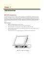
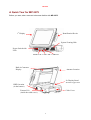
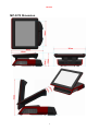
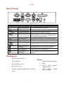
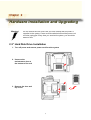
User's Manual
Mega POS MP-3000 Series
MP-3275
15” Dual-Core High-Performance
POS system
Copyright Notice
This document is copyrighted, © 2008. All rights are reserved. Firich Enterprise Co., Ltd reserves
the right to make improvements of the product described in this manual at any time without notice.
No part of this manual may be reproduced, copied, translated, or transmitted in any form or by
any means without the prior written permission from Firich Enterprise Co., Ltd. Information
provided in this manual is intended to be accurate and reliable. However, Firich Enterprise Co.,
Ltd assumes no responsibility for its use, nor for any infringements upon the rights of third parties,
which may result from its use.
The material in this document is for product information only and is subject to change without
notice. While reasonable efforts have been made in the preparation of this document to assure its
accuracy, Firich Enterprise Co., Ltd, assumes no liabilities resulting from errors or omissions in
this document, or from the use of the information contained herein.
Safety and Warranty
1. Read these safety instructions carefully.
2. Keep this user's manual for later reference.
3. Disconnect this equipment from any AC outlet before cleaning. Do not use liquid or spray
detergents for cleaning. Use a damp cloth.
4. For pluggable equipment, the power outlet must be installed near the equipment and must be
easily accessible.
5. Keep this equipment away from humidity.
6. Put this equipment on a reliable surface during installation. Dropping it or letting it fall could
cause damage.
7. The openings on the enclosure are for air convection. Protect the equipment from overheating.
DO NOT COVER THE OPENINGS.
8. Make sure the voltage of the power source is correct before connecting the equipment to the
power outlet.
9. Position the power cord so that people cannot step on it. Do not place anything over the power
cord.
10. All cautions and warnings on the equipment should be noted.
11. If the equipment is not used for a long time, disconnect it from the power source to avoid
damage by transient over-voltage.
12. Never pour any liquid into an opening. This could cause fire or electrical shock.
13. Never open the equipment. For safety reasons, only qualified service personnel should open
the equipment.
14. If any of the following situations arises, get the equipment checked by service personnel:
a. The power cord or plug is damaged.
b. Liquid has penetrated into the equipment.
c. The equipment has been exposed to moisture.
d. The equipment does not work well, or you cannot get it to work according to the user’s manual.
e. The equipment has been dropped and damaged.
f. The equipment has obvious signs of breakage.
15. DO NOT LEAVE THIS EQUIPMENT IN AN UNCONTROLLED ENVIRONMENT WHERE
THE STORAGE TEMPERATURE IS BELOW -20° C (-4°F) OR A BOVE 60° C (140° F). IT MAY
DAMAGE THE EQUIPMENT.
Table of Content
Chapter 1
Introduction
1
1
MP-3275 Introduction........................................................................................................... 1
A Quick Tour for MP-3275 ................................................................................................... 2
MP-3275 Dimension ..................................................................................................... 3
Rear I/O Panel..................................................................................................................... 4
Packing List ......................................................................................................................... 4
Chapter 2
Hardware Installation and Upgrading
5
5
2.5” Hard Disk Drive Installation.................................................................................... 5
Pole-Type VFD Installation ........................................................................................... 6
Memory (DDRII RAM) / CPU / DOM Installation ........................................................... 7
Compact Flash Card (CF) Installation ........................................................................... 7
MCR Parameter Modification ........................................................................................ 8
Cash Drawer Installation............................................................................................... 8
Chapter 3
Software Installation and Setup
9
9
Please follow this installation sequence. .............................................................................. 9
Intel Chipset Driver Installation for Windows XP & Vista ...................................................... 9
VGA Driver Installation....................................................................................................... 13
945GC Driver Installation for Windows XP & Vista...................................................... 13
LAN Driver Installation ....................................................................................................... 16
LAN Driver Installation for Windows XP & Vista. ......................................................... 16
Audio Driver Installation ..................................................................................................... 20
Audio Driver Installation for Windows XP & Vista........................................................ 20
ELO Touch Tools Installation ............................................................................................. 22
ELO Touch Tools Installation for Windows XP & Vista................................................ 22
ELO Control Panel...................................................................................................... 27
TouchKit Tools Installation................................................................................................. 30
Fuji TouchKit Installation for Windows XP & Vista....................................................... 30
TouchKit Control Panel ............................................................................................... 34
Chapter 4
Specifications
35
35
MP-3275 Specifications ..................................................................................................... 35
Chapter 5
Troubleshooting
37
37
Display Does Not Show Properly Under DOS Mode ................................................... 37
Touch Panel Does Not Work....................................................................................... 37
ELO Touch Panel Cannot Calibrate Correctly ............................................................. 37
LAN Is Not Functioning Properly ................................................................................. 38
COM1, COM2, COM5 Are Not Functioning Properly................................................... 38
Cash Drawer Port Is Not Functioning Properly............................................................ 38
USB Device Is Not Functioning Properly..................................................................... 38
MP-3275
Chapter 1
Introduction
MP-3275 Introduction
Combining high performance with cost-effective design concept, MP-3275 is a decent choice for
budget-concerning customers. The sturdy but shaped plastic mechanical design represents FEC’s
persistence in quality and taste. With abundant I/O access, MP-3275 provides great connectivity
and considerable integrated peripheral options. Equipped with 270W power supply, the terminal
is powerful enough to run Dual-Core CPU and to drive devices powered from the system COM
ports.
Main Features:
•
•
•
•
•
Built-in customer display for space saving
Front panel IP54 compliant for dust and water spill resistance
Easy maintenance for system parts, such as HDD, CF, RAM, and CPU
Strong system performance boost possibility with Dual-Core CPU support and 2 x
memory DIMM sockets
Integrated cable cover for supporting pole-type VFD and cable management
MP-3275 w/ cable cover & MCR
1
MP-3275
A Quick Tour for MP-3275
Before you start, take a moment to become familiar with MP-3275.
1st Display
Identification Device
System Venting Hole
Power Switch with
LED
HDD LED / LAN LED / USB Port
Built-in Customer
Display
Antenna Location
2nd Display Stand
for Pole-Type VFD
HDD Location
(in the bottom)
Cable Cover
External I/O
(inside the cable cover)
2
MP-3275
MP-3275 Dimension
3
MP-3275
Rear I/O Panel
I/O Port
Connector Type
Description
Earphone connector
Connect the speakers to this port
USB type A connector Standard USB connector for external device
DC Power connector
Connect the power supply to this port
VFD / RJ45 connector This RJ45 port can be used to attach a VFD
customer display or serve as an additional serial
port (switching cable provided).
RJ11 connector
Cash Drawer Connector, 12 V actuation support
PS2 connector
Connect the keyboard or mouse to this port
D-SUB 9 connector
The serial ports COM1/COM2 can be used to
connect devices such as a printer or a fax/modem.
Parallel 25-pin LPT
Connector
RJ45 connector
The standard LPT (D-SUB 25 pin) connector for
connecting POS printers or KeyPro solution
Connect MP-3275 to the Ethernet
D-Sub 15 Pin
Connector
The VGA port is used for connecting LCD or CRT
monitors
Packing List
•
MP-3275 Main System x 1
•
Power Supply x 1
•
Pole-type Customer Display
•
Driver & Manual CD x 1
•
MCR
•
AC Power Cord x 1
•
Built-in LCM
Display Module
•
COM port switching cable (RJ45 to D-SUB 9
•
WiFi / CDMA /
Wireless Module
Optional:
pin) x 1
4
Customer
GPRS
MP-3275
Chapter 2
Hardware Installation and Upgrading
Do not remove the rear cover until you have verified that no power is
supplied to the system. Power must be switched off and the power cord
must be unplugged. Every time you service the system, you should be
aware of this.
2.5” Hard Disk Drive Installation
1. Turn off power and remove power cord from the system
2. Unscrew the
maintenance door at
the bottom of the unit
3. Remove the door and
flip it over
5
MP-3275
4. Place HDD kit on the
door, fasten it with 4
screws and connect
with the SATA cable.
2.5”
HDD
SATA cable
5. Restore the maintenance door to the system.
6. Fix the door with the screw.
7. Connect the power cord to the system.
Pole-Type VFD Installation
1. Remove the plastic
cover on the cable
cover
2. Fix the pole stand with
screws and place the
pole-type customer
display to the stand
3. Connect the RJ45 or RS-232 (D-Sub 9) cable to the system.
6
MP-3275
Memory (DDRII RAM) / CPU / DOM Installation
1.
Unscrew and remove
the top cover
2.
Install the DDRII RAM or CPU you require
3.
Restore the top cover
Compact Flash Card (CF) Installation
4.
Unscrew and remove
the maintenance door
5.
Install the CF you require
6.
Restore the maintenance door
7
MP-3275
MCR Parameter Modification
This option is for users who need to customize the MCR parameters for a particular task.
Some of the useful parameters include:
The selection of country code, other than the default English.
The choice of track combinations.
The preamble/post amble codes.
The MCR parameters can be modified by using the supplied utility program.
The utility can be found on the CD that came with your system in the “Utilities” folder. The
program name is msr_v12_win.zip.
Cash Drawer Installation
Before connecting the cash drawer to the MP-3275, please make sure the drive voltage and cable
pin assignment of the cash drawer matches the definition of the cash drawer port of MP-3275.
Please refer to the mother board manual GPIO part for more information.
Plug cash drawer cable into the cash drawer port.
Note: If the cash drawer cannot be detected by the system, please refer to troubleshooting.
Up to two cash drawers may be driven from this port. Driving voltage of the solenoid is DC+12V.
I/O port 2F is used for drawer operation. A test program is supplied, for Linux and Windows,
source code of which is available on request by software developers.
To test for drawer open, read port 2F, if bit 0=1 then drawer is open, if bit 0=0 drawer is closed.
Before testing the cash drawer function, ensure to initiate the GPIO port first referring to the
command sets below:
initGPIO=2e,87,2e,87,2e,07,2f,07,2e,f1
( 2e stands for the address while ‘87’, ‘07’, ‘f1’ stands for the value to the address. All the values here are
hexadecimal.)
8
MP-3275
Chapter 3
Software Installation and Setup
MP-3275 comes with a variety of drivers for different operating systems.
You may find the system CD with all the necessary drivers and utilities.
Please follow this installation sequence.
Driver installation sequence:
Chipset Driver -> VGA Driver -> LAN Driver -> Audio Driver ->Touch Tools
The reason to follow our sequence is that IRQ settings will be changed by Windows XP and Vista
to non supported values, and you may encounter unnecessary problems later.
Intel Chipset Driver Installation for Windows XP & Vista
1. Insert the CD into your CD ROM Drive.
2. Locate the folder of D:\DRIVER\CHIPSET\
3. Open Setup.exe
4. Click Next.
9
MP-3275
5. Read the License Agreement and click Yes.
6. Click Next and the drivers for the Intel Chip set will install.
10
MP-3275
7. Please wait while the setup program processing.
(for Windows XP)
11
MP-3275
(for Windows Vista)
8. When the 'Setup COMPLETE' message appears click Finish to restart your computer.
12
MP-3275
VGA Driver Installation
945GC Driver Installation for Windows XP & Vista
1. Locate the folder of D:\Driver\Graphics\WinXP_2K\
2. Open win2k_xp14324.exe
3. Select Next to continue.
4. Select Next to continue.
13
MP-3275
5. Read the License Agreement and click Yes.
6. Click Next to see the setup progress.
14
MP-3275
7. Select Next to continue.
8. Click Finish to complete the installation procedure and restart the system.
15
MP-3275
LAN Driver Installation
LAN Driver Installation for Windows XP & Vista.
1. Locate D:\Driver\Ethernet\WinXP_2k\
2. Double click Setup.exe.
(for Windows XP)
(for Windows Vista)
3. Click Next to continue
16
MP-3275
(for Windows XP)
(for Windows Vista)
4. Click Next to continue
17
MP-3275
(for Windows XP)
(for Windows Vista)
5. Please wait while processing.
18
MP-3275
(for Windows XP)
(for Windows Vista)
6. Click Finish to complete the installation procedure.
19
MP-3275
Audio Driver Installation
Audio Driver Installation for Windows XP & Vista
1. Locate D:\Driver\Audio\WinXP_Vista_2k\
2. Double click Setup.exe.
3. Click Next to continue.
4. Click Next to continue.
20
MP-3275
5. Click Finish and restart the system.
21
MP-3275
ELO Touch Tools Installation
ELO Touch Tools Installation for Windows XP & Vista
1. Locate D:\Driver\TouchScreen\ELO Touch\XP_Vista\
2. Open SW600650.exe
3. Click OK to continue.
4. Click Unzip to continue the installation.
5. Click OK to continue.
22
MP-3275
6. Pick the default language for the Elo Touchscreen and click Next to continue.
7. Check “Install serial Touchscreen Drivers” And click Next.
8. Read the “License Agreement” and click Yes if you accept it.
23
MP-3275
9. Select “Auto-detect Elo touchscreens” and click Next.
10. Select the COM port for the touch monitor. It is recommended that you select COM3 for
the touch screen, as this port is internally configured for touch operation. And click Next to
continue.
11. Make sure the COM port listed is the one you chose for your touch monitor. Press Next to
continue.
24
MP-3275
12. Wait until the ELO Touch Tools installation finished.
13. Select “Calibrate ELO Touchscreen monitors” and click Finish.
14. Start calibrating the touchscreen by touch the targets showed on the screen.
25
MP-3275
15. If the cursor is working fine, click
screen again.
to finish the setting; if not, click
to calibrate the
IT MAY BE NECESSARY TO RESTART YOUR COMPUTER TO UTILIZE YOUR
TOUCHSCREEN FEATURES.
16. Click Restart to reboot your computer again.
26
MP-3275
ELO Control Panel
This section explains the different options in the ELO control Panel.
General tab
The general tab allows you to:
•
Change the COM port your touch screen is set to.
•
Calibrate the touch screen with the Align button.
Mode tab
The Buttons tab allows you to:
•
Adjust all mouse emulation controls.
•
Change cursor properties
•
Enable or disable right mouse button utility.
27
MP-3275
Sound tab
The Sound tab allows you to:
•
To change sound properties for ELO touch tools.
Properties tab
The Diagnostics tab allows you to:
•
View Controller Information.
28
MP-3275
About tab
The About tab displays Information about ELO Touch systems
29
MP-3275
TouchKit Tools Installation
Fuji TouchKit Installation for Windows XP & Vista
1. Locate D:\Utility\TouchScreen\TouchKit(Fujitsu)\Windows 2000 XP\
2. Select the relevant folder for the operating system that you are using.
3. Open Setup.exe
4. Click Next
5. Click Next
30
MP-3275
6. Click Next
7. Click OK to close the pop-up dialog.
8. Click “Support Multi-Monitor System” and then Next to continue.
31
MP-3275
9. Click Next
10. Click Next
32
MP-3275
11. Click Yes
(for Windows XP)
(for Windows Vista)
12. Click OK and turn off the computer to restart your system again.
After the system finish rebooting follow the directions to calibrate the Touch screen.
33
MP-3275
TouchKit Control Panel
This section explains the different options in the TouchKit control Panel.
General tab
The general tab allows you to:
•
Manage the touch screen controller you installed.
Tools tab
The tools tab allows you to:
•
Calibrate the touch screen with the 4 Points Calibration button.
34
MP-3275
Chapter 4
Specifications
MP-3275 Specifications
System Configuration
CPU (LGA775)
INTEL® Celeron 440 (2.0GHz) or Dual Core E2160 (1.8GHz)
Chipset
Intel® 82945GC GMCH
South Bridge
Intel® 82801GB ICH7
Memory
Support Two DDRII 400/533MHz SDRAM up to 2GB
VGA controller
Integrated in 945GC (Graphics Media Accelerator 950). Up to
224MB maximum video memory, allocating system memory
dynamically
Primary LCD Panel
15” TFT LCD Panel (1024x768).
Primary Touch
Panel
15” with Fuji 4-wire or ELO 5-wire resistive touch panel
Storage
Internal 2.5” Serial ATA 80GB hard disk drive as default
Support type II Compact Flash™ Disk. IDE interface
Support IDE-44 pin DOM
Speaker
Integrated 2W x 2 stereo system speakers
Power
270 watts external power supply
I/O Port
Serial Port
3 User available COM ports (COM1, COM2, COM5).
2 System assigned COM ports (COM3 & COM4).
COM3 for primary touch screen.
COM4 for built-in LCM customer display
1 Reserved (COM6).
Enhanced Parallel
Port
Support EPP/SPP/ECP
35
MP-3275
USB port
8 USB 2.0 ports (3*Internal, 5*External)
Cash drawer port
RJ11 Cash drawer port,12V actuation.
Keyboard Port
One PS/2 keyboard port.
LAN Port
10/100M Base-T Ethernet Controller, Realtek RTL8102E
VGA Port
Standard D-SUB 15 Pin VGA Port
Audio Port
Integrated Sound Blaster compatible, AC97 Audio Codec. (Realtek
ALC662)
Optional Features
Customer display
MSR
External Magnetic Stripe Card Reader track 1/2/3
Wireless
Built-in LCM module
Pole-type VFD customer display
Internal WiFi Module(USB)
Internal CDMA or GPRS Module (RS-232)
Power Consumption
Power
consumption
150W
(Standard system while running programs and accessing HDD).
Operating temperature
Operating
temperature
0 ℃ ~ 40 ℃
36
MP-3275
Chapter 5
Troubleshooting
Please note that the following troubleshooting guide is designed for people with strong computer
hardware knowledge such as System Administrators and Engineers.
Display Does Not Show Properly Under DOS Mode
A) Enter BIOS setup program and then get into the Boot Display option. Check if the default
setting is [ Auto ]; if not, change the setting to [ Auto ] and press F10 to save the settings.
B) Due to the chipset limitation, while two displays are connected to the system, both display
contents will shrink and cannot show properly in size under DOS mode. After the system
booting completed and running under the Windows OS, the display will show in normal
size. Such situation appears both in 945GC and 945G chipsets.
Touch Panel Does Not Work
A)
Check CMOS settings, COM3 needs to be “Enabled”. The correct settings are “4E0” and
“IRQ10”.
B)
Check if there are no conflicts between COM3 IRQ10 and any other devices.
C)
Check if the ELO driver or the TouchKit driver has been properly installed. Or try to reinstall again (Please refer to the ELO driver installation or the TouchKit driver).
D)
Check if the ELO controller or the TouchKit driver on COM3 has been detected during
the ELO driver or the TouchKit driver installation. If yes, then check if the flat cable from
the ELO touch screen or the TOUCHKIT touch screen has been properly connected to
the ELO controller or the TouchKit controller (Attention: Pin1 mark should be on the
same side as the ELO controller).
E)
Check if the ELO controller Green LED is blinking?
If no, there is no DC+5V support for the ELO controller from the motherboard.
F)
Touch screen controller could be defective or the touch panel could be defective.
ELO Touch Panel Cannot Calibrate Correctly
A)
Please replace the ELO controller, and re-calibrate. If this works, change back to the
original ELO controller, and re-calibrate.
B)
If the ELO touch panel still cannot calibrate correctly after changing to a new ELO
controller, the touch panel may be not installed properly or it could be defective.
37
MP-3275
LAN Is Not Functioning Properly
A)
Check if the LAN driver is installed properly. (Please refer to the LAN driver installation)
B)
Check if there are any IRQ conflicts.
C)
Check if the RJ45 cable is properly connected.
D)
The on board LAN chip could be defective.
COM1, COM2, COM5 Are Not Functioning Properly
A)
Check if the I/O ports are enabled in the CMOS setup.
B)
Check if there are any IRQ conflicts.
C)
The motherboard could be defective.
Cash Drawer Port Is Not Functioning Properly
A)
Make sure the pin assignment matches between the cash drawer and the RJ11 cash
drawer port.
B)
Verify the digit I/O port address is 2F
C)
The motherboard could be defective.
USB Device Is Not Functioning Properly
A)
Ensure that the USB controller is “enabled” in the CMOS setup.
B)
Ensure that the USB Legacy is “enabled” in the CMOS setup. (Windows 2000、Window
XP Professional)
C)
Ensure that the USB Legacy is “Disabled” in the CMOS setup. (Embedded OS:
Windows XP Embedded、Window CE. NET、Linux RedHat 9)
38