1
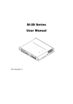
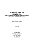
User's Manual
AL-9700 Series
AL-9705
15” Dual-Core Media-Enhanced
POS system
Copyright Notice
This document is copyrighted, © 2009. All rights are reserved. Firich Enterprise Co., Ltd reserves
the right to make improvements of the product described in this manual at any time without notice.
No part of this manual may be reproduced, copied, translated, or transmitted in any form or by
any means without the prior written permission from Firich Enterprise Co., Ltd. Information
provided in this manual is intended to be accurate and reliable. However, Firich Enterprise Co.,
Ltd assumes no responsibility for its use, nor for any infringements upon the rights of third parties,
which may result from its use.
The material in this document is for product information only and is subject to change without
notice. While reasonable efforts have been made in the preparation of this document to assure its
accuracy, Firich Enterprise Co., Ltd, assumes no liabilities resulting from errors or omissions in
this document, or from the use of the information contained herein.
Safety and Warranty
1. Read these safety instructions carefully.
2. Keep this user's manual for later reference.
3. Disconnect this equipment from any AC outlet before cleaning. Do not use liquid or spray
detergents for cleaning. Use a damp cloth.
4. For pluggable equipment, the power outlet must be installed near the equipment and must be
easily accessible.
5. Keep this equipment away from humidity.
6. Put this equipment on a reliable surface during installation. Dropping it or letting it fall could
cause damage.
7. The openings on the enclosure are for air convection. Protect the equipment from overheating.
DO NOT COVER THE OPENINGS.
8. Make sure the voltage of the power source is correct before connecting the equipment to the
power outlet.
9. Position the power cord so that people cannot step on it. Do not place anything over the power
cord.
10. All cautions and warnings on the equipment should be noted.
11. If the equipment is not used for a long time, disconnect it from the power source to avoid
damage by transient over-voltage.
12. Never pour any liquid into an opening. This could cause fire or electrical shock.
13. Never open the equipment. For safety reasons, only qualified service personnel should open
the equipment.
14. If any of the following situations arises, get the equipment checked by service personnel:
a. The power cord or plug is damaged.
b. Liquid has penetrated into the equipment.
c. The equipment has been exposed to moisture.
d. The equipment does not work well, or you cannot get it to work according to the user’s manual.
e. The equipment has been dropped and damaged.
f. The equipment has obvious signs of breakage.
15. DO NOT LEAVE THIS EQUIPMENT IN AN UNCONTROLLED ENVIRONMENT WHERE
THE STORAGE TEMPERATURE IS BELOW -20° C (-4°F) OR A BOVE 60° C (140° F). IT MAY
DAMAGE THE EQUIPMENT.
Table of Content
Chapter 1
Introduction
1
1
AL-9705 Introduction............................................................................................................ 1
A Quick Tour for AL-9705 .................................................................................................... 2
AL-9705 Dimension ...................................................................................................... 3
Rear I/O Panel..................................................................................................................... 4
Packing List ......................................................................................................................... 5
Chapter 2
Hardware Installation and Upgrading
6
6
2 x 2.5” Hard Disk Drive Installation .............................................................................. 6
Pole-Type VFD / 2nd LCD Display Installation ............................................................... 7
Memory (DDRII RAM) / CPU Installation....................................................................... 8
Jumper Setting Adjustment ........................................................................................... 8
MCR Parameter Modification ........................................................................................ 9
i-Button Installation ....................................................................................................... 9
Cash Drawer Installation............................................................................................. 10
Chapter 3
Software Installation and Setup
11
11
Please follow this installation sequence. ............................................................................ 11
AMD Chipset Driver Installation for Windows XP ............................................................... 11
NetFramework Installation .......................................................................................... 14
LAN Driver Installation ....................................................................................................... 16
LAN Driver Installation for Windows XP ...................................................................... 16
Audio Driver Installation ..................................................................................................... 18
Audio Driver Installation for Windows XP .................................................................... 18
ELO Touch Tools Installation ............................................................................................. 19
ELO Control Panel...................................................................................................... 24
TouchKit Tools Installation (Fujitsu) ................................................................................... 27
Fuji TouchKit Control Panel ........................................................................................ 32
Wireless LAN Driver Installation......................................................................................... 36
Utility Settings and Illustration ............................................................................................ 39
Dual Display Settings.................................................................................................. 39
RAID Function BIOS Settings ..................................................................................... 41
Realtek Audio Tool Settings for Dual Strings............................................................... 48
Chapter 4
Specifications
50
50
AL-9705 Specifications ...................................................................................................... 50
Chapter 5
Troubleshooting
52
52
ELO Touch Panel Cannot Calibrate Correctly ............................................................. 52
LAN Is Not Functioning Properly ................................................................................. 52
COM2 / 3 / 4 / 5 / 6 Are Not Functioning Properly ....................................................... 52
Cash Drawer Port Is Not Functioning Properly............................................................ 52
USB Device Is Not Functioning Properly..................................................................... 53
RAID Driver Installation Cannot Work via USB Floppy Disk in Windows XP ............... 53
AL-9705
Chapter 1
Introduction
AL-9705 Introduction
Combining POS application with HD level media performance, AL-9705 leads the POS terminal
development into a new era. With the ATI HD3200 graphic IC integrated and optional side-port
memory support, it becomes possible for a POS terminal to be more than a POS—it can also serve
as a digital signage player. Besides the excellent media enhanced features, AL-9705 is equally
strong in POS application features, such as dual-core CPU support, 2 x HDD with RAID function,
abundant I/O access, and easy-maintenance mechanical structure. Though as powerful as it is,
AL-9705 is supplied with a 150W power adaptor only, reducing the power consumption efficiently
as a little tribute to our planet.
Main Features:
•
•
•
•
•
•
Multiple display with independent audio stream support
Strong graphic performance, supporting mpeg2/4, H.264…etc
2 x HDD trays available with RAID function support
Integrated OSD and monitor power indicator for better display monitoring
Easy maintenance for HDD, RAM, and the M/B box
Easy access for jumper setting adjustment
AL-9705 (Black & Silver v.s. Silver & White)
1
AL-9705
A Quick Tour for AL-9705
Before you start, take a moment to become familiar with AL-9705.
Identification Device
(MSR/IC Card Reader/
RFID or Finger Print)
1st Display
System Venting Hole
Monitor Power LED
& System Power LED
i-Button (optional)
Monitor OSD
(On/OFF, Brightness
Up & Down
System Venting Hole
Side I/O with Lid
(USB x 2/Power Switch)
HDD Tray Cover
Antenna Location
2nd Display Stand
Location for Pole-Type
VFD / LCD Displays
Cable Cover
2
AL-9705
AL-9705 Dimension
3
AL-9705
Rear I/O Panel
I/O Port
Connector Type
Description
Earphone connector
Connect the speakers to this port
USB type A connector Standard USB connector for external device
DC Power connector
Connect the power supply to this port
VFD / RJ45 connector This RJ45 port can be used to attach a VFD
w/ LED Indicators
customer display or serve as an additional serial
(5V/12V)
port (switching cable provided). (Green LED for
5V/ Orange LED for 12V/ None for RI.)
RJ11 connector
PS2 connector
D-SUB 9 connector
10-pin RJ45 10P10C
Connector
RJ45 connector
D-Sub 15 Pin
Connector
20 Pin Display Port
Connector (Male)
12V DC-out
connector
Cash drawer connector, 12V / 24V selectable by
jumper (JP7)
Connect the keyboard or mouse to this port
The serial ports COM5/COM6 can be used to
connect devices such as a printer or a fax/modem.
The RJ45 connector is for connecting LPT-type
KeyPro solution
Connect AL-9705 to the Ethernet
The VGA port is used for connecting LCD or CRT
monitors or pole-type 2nd LCD customer displays.
The display port can be used to connect HD level
resolution displays (cable adaptors for DP to
VGA/DVI/HDMI are optionally provided.)
This DC-out port can sustain the power of the
monitor or any other devices which need 12V DC
power input.
4
AL-9705
Packing List
Optional:
•
AL-9705 Main System x 1
•
2nd 2.5” HDD Tray
•
150W Power Adaptor x 1
•
Pole-type 12” /15” LCD Customer
Display
•
Driver & Manual CD x 1
•
•
AC Power Cord x 1
MCR / IC Card Reader / Finger
Print or RFID Selectable 3-in-1
Module
•
2.5” HDD Tray x 1
•
I-Button (by factory order)
•
COM port switching cable (RJ45 to
•
WiFi Wireless Module
•
DP Cable Adaptors: DP to VGA /
DVI / HDMI Available
D-SUB 9 pin) x 3
5
AL-9705
Chapter 2
Hardware Installation and Upgrading
Do not remove the rear cover until you have verified that no power is
supplied to the system. Power must be switched off and the power cord
must be unplugged. Every time you service the system, you should be
aware of this.
2 x 2.5” Hard Disk Drive Installation
1. Turn off power and remove power cord from the system
2. Unlock the HDD tray
cover in front and
reveal the HDD trays
(One tray as default).
3. Push the tray button
and pull out the tray
module to replace the
HDD.
4. Restore the HDD tray to the system.
5. Lock the HDD tray cover.
6. Connect the power cord to the system.
6
AL-9705
Pole-Type VFD / 2nd LCD Display Installation
1. Remove the lid on the
cable cover
2. Fix the pole stand with
screws and place the
pole-type customer
display / 2nd LCD
display to the stand
3. Connect the RJ45 or
RS-232 (D-Sub 9) cable
to the system for VFD.
4. Connect VGA (D-Sub
15) and 12V DC power
cables to the system for
2nd LCD display
7
AL-9705
Memory (DDRII RAM) / CPU Installation
1.
Unscrew and remove
the top cover
2.
Install the DDRII RAM or CPU you require.
3.
Restore the top cover.
Jumper Setting Adjustment
1. Unscrew and remove
the maintenance door
JP1
JP2
2. Adjust the jumper
settings required.
(See the Note below for
setting details.)
3. Restore the maintenance door.
8
JP3
JP4
JP6
JP5
JP7
AL-9705
Note:
MCR Parameter Modification
This option is for users who need to customize the MCR parameters for a particular task.
The MCR parameters can be modified by using the supplied utility program.
The utility can be found on the CD that came with your system in the “\Utilities\USB
MSR\Software” folder. The program name is HID_MSR_PSW00003.exe.
And the utility user manual can be found in “\Utilities\USB MSR\Documents\
HidMsrUserManual_TM970001.pdf.”
i-Button Installation
The i-Button applied in AL-9700 is a COM-interfaced device which simulates K/B input as default
application. The testing program “iButtonTester” may be retrieved from our technical website.
The command set is shown as follows.
Command
ESC w
Interpret
Read iButton Key
Note:
1. Put the key to i-button reader to generate an interrupt and send the key data to the terminal.
2. Remove the key from i-button reader to generate an interrupt and send '0 0 0 0 0 0' to the
terminal.
9
AL-9705
Cash Drawer Installation
Before connecting the cash drawer to the AL-9705, please make sure the drive voltage and cable
pin assignment of the cash drawer matches the definition of the cash drawer port of AL-9705.
Please refer to the mother board manual GPIO part for more information.
Plug cash drawer cable into the cash drawer port.
Note: If the cash drawer cannot be detected by the system, please refer to troubleshooting.
Up to two cash drawers may be driven from this port. Driving voltage of the solenoid is DC+12V /
24V selectable (via JP7). I/O port 2F is used for drawer operation. A test program is supplied, for
Linux and Windows, source code of which is available on request by software developers. OPOS
driver, test software and sample dll files can be found under the Utility folder in the system driver
CD attached.
(DLL Library: Utilities\Cash Drawer\cashdrawerdll\
Test Program: \Utilities\Cash Drawer\cashdrawertest\)
To test for drawer open, read port 2F, if bit 0=1 then drawer is open, if bit 0=0 drawer is closed.
Before testing the cash drawer function, ensure to initiate the GPIO port first referring to the
command sets below:
initGPIO=2e,87,2e,87,2e,07,2f,07,2e,f1
( 2e stands for the address while ‘87’, ‘07’, ‘f1’ stands for the value to the address. All the values here are
hexadecimal.)
10
AL-9705
Chapter 3
Software Installation and Setup
AL-9705 comes with a variety of drivers for different operating systems.
You may find the system CD with all the necessary drivers and utilities.
Please follow this installation sequence.
Driver installation sequence:
Chipset Driver NetFramework LAN Driver Audio Driver Touch Tools Utilities
The reason to follow our sequence is that IRQ settings will be changed by Windows XP to non
supported values, and you may encounter unnecessary problems later.
AMD Chipset Driver Installation for Windows XP
The AMD 780E driver installation will include not only the chipset drivers, but also the built-in ATI
utilities for graphics (Catalyst Control Center), audio and RAID function. During the installation,
the system will show the message requesting the installation of NetFramework. Please direct
manually to the folder to complete the process.
1. Insert the CD into your CD ROM Drive.
2. Locate the folder of D:\Driver\CHIPSET\WinXP\
3. Open Setup.exe
4. Click Next.
11
AL-9705
5. Read the License Agreement and click Yes.
6. Click Express: Recommended to start the installation.
12
AL-9705
7. Please wait while the setup program processing.
8. Click OK to continue.
9. Please wait for the configuration process.
13
AL-9705
10. When the 'Setup Complete' message appears, click Finish to restart your computer.
NetFramework Installation
1. Locate D:\ Driver \CHIPSET\Win XP\Net Framework 2.0\
2. Open dotnetfx.exe
3. Click Next to continue.
14
AL-9705
4. Tick I accept the terms of the License Agreement and click Install to continue.
5. Click Finish to complete the installation.
15
AL-9705
LAN Driver Installation
LAN Driver Installation for Windows XP
1. Locate D:\Driver\GIGA LAN\WinXP\
2. Double click Setup.exe.
3. Click Next to continue
4. Click Next to continue
16
AL-9705
5. Click Continue Anyway to continue the installation.
6. Click Finish to complete the installation procedure.
17
AL-9705
Audio Driver Installation
Audio Driver Installation for Windows XP
1. Locate D:\Driver\AUDIO\WinXP\
2. Double click Setup.exe.
3. Click Next to continue.
4. Click Finish to restart the system.
18
AL-9705
ELO Touch Tools Installation
1.
Locate D:\Utilities\TOUCHSCREEN\ELO Touch\WinXP\
2.
Select the relevant ELO folder for the operating system that you are using. For example. If
you are installing for a Windows XP then select WinXP folder.
3.
Open EloSetup.exe
4.
Click OK to extract the necessary files
5.
Click OK to install Elo Touch drivers and utilities.
19
AL-9705
6.
Select Default and click Next to continue.
7.
Tick the Install USB Touchscreen Drivers and click Next to continue.
20
AL-9705
8.
Read the “License Agreement” and click Yes if you accept it.
9.
Please wait for the installation to be completed.
21
AL-9705
10. Select Calibrate Elo Touchscreen monitors and click Finish to start the calibration.
11. Please use a soft-tip object such as finger to calibrate the touch screen (Red bull’s eye
will pop up three times in different positions)
22
AL-9705
12. Click "
” to finish the installation
23
AL-9705
ELO Control Panel
This section explains the different options in the ELO control Panel.
General tab
The General tab allows you to calibrate the touch screen with the Align button.
24
AL-9705
Mode tab
The Mode tab allows you to:
•
Adjust all mouse emulation controls.
•
Change cursor properties
•
Enable or disable right mouse button utility.
Sound tab
The Sound tab allows you to:
•
To change sound properties for ELO touch tools.
25
AL-9705
Properties tab
The Properties tab allows you to:
•
View Controller Information.
About tab
The About tab displays Information about ELO Touch systems
26
AL-9705
TouchKit Tools Installation (Fujitsu)
1. Locate D:\Utilities\TOUCHSCREEN\TouchKit(Fujitsu)\WinXP
2. Select the relevant folder for the operating system that you are using. For example. If you
are installing for a Windows XP then select WinXP folder.
3. Click Setup.exe
4. Click Next
5. Click Next (ignore optional item)
27
AL-9705
6. Click Next (set optional item as None)
7. Click OK
28
AL-9705
8. Click Next (Support Multi-Monitor System)
9. Click Next to start install
29
AL-9705
10. Click Next to continue.
11. System will automatically detect the interface that touch sensor is connected (Factory
setting is USB port).
12. Click Yes to continue the calibration procedures
30
AL-9705
13. Please use a soft-tip object such as finger to calibrate the touch screen (Red bull’s eye will
pop up four times in different positions)
14. Click OK to finish the calibration.
31
AL-9705
Fuji TouchKit Control Panel
This section explains the different options in the TouchKit control Panel.
General tab
The general tab allows you to:
•
View the interface your touch screen is set to.
Setting tab
The Setting tab allows you to:
•
Set Beeper, Double Click and Linearization Style.
32
AL-9705
Tool tab
The Tool tab allows you to:
•
Calibrate the touch screen with the 4 pts Cal button.
Display tab
The Display tab allows you to:
•
Set Display mode
33
AL-9705
Edge Compensation Tab
The Edge Compensation tab allows you to set edge compensation to improve touch accuracy
Hardware tab
The Hardware tab shows the Touch screen hardware version information
34
AL-9705
About tab
The About tab show the Utility version information
35
AL-9705
Wireless LAN Driver Installation
1.
Locate D:\Utilities\Wireless LAN\Ralink
2.
Open Setup.exe
3. Click “Next” and start the installation
4. Select “Ralink Configuration Tool” and click Next to continue.
36
AL-9705
5. Select “Optimize for WiFi mode” and click Next to continue.
6. Click Install to continue.
37
AL-9705
7. Wait while the installation is processing.
8. Click “Finish” to complete the installation.
38
AL-9705
Utility Settings and Illustration
Dual Display Settings
The ATI Catalyst Control Center is the utility that allows the user to adjust graphics-related
properties and features easily. Detailed settings guide can be found from the Help center
provided in the utility.
1. Locate Catalyst Control Center from the startup menu.
2. Select Advanced mode to continue the settings.
3. Click Yes to continue.
39
AL-9705
4. Select the options required to be adjusted from the left-side pull-down list.
5. Select Display Properties from the menu to set the dual display options. Click OK to
save the adjusted settings.
40
AL-9705
RAID Function BIOS Settings
To enable the RAID function in the system, please complete the following steps illustrated basing
on Windows XP.
1. During system booting, press <DEL> key to enter the BIOS setup menu.
2. Enter OnChip SATA Device and select OnChip SATA Type to [ RAID ]. Press <F10> to
save the setting and wait for the computer to reboot.
3. Press <Ctrl-F> to enter the RAID Option ROM Utility.
41
AL-9705
4. Press <2> to enter the RAID settings.
5. Set the RAID Mode (RAID0/1/10/JBOD/RAID Ready) to the one desired. Set to RAID 0
for mirror function and set Assignment to Y for both drives. Press <Ctrl-Y> to continue.
42
AL-9705
6. Press <Ctrl-Y> to continue the setting.
7. Press <Enter> to continue.
43
AL-9705
8. Press <Y> to reboot the system.
9. Press <F6> to install the RAID driver via a floppy disk. The Win XP drivers required may
be found in the driver CD “\ Driver\RAID -OS install\Floppy_AA780W \”. As for Win7, the
drivers were built in already in the OS. There would be no need to install extra drivers for
RAID function.
(Note: If the RAID driver installation cannot succeed in the Windows XP OS, please refer to
the Troubleshooting.)
44
AL-9705
10. Press <S> to specify additional device.
11. Insert the driver disk to the assigned location and press <Enter> to continue.
12. Select AMD AHCI Compatible RAID Controller-x86 platform to continue.
45
AL-9705
13. Press <F3> to finish.
Note:
A remote RAID control utility (RAIDXpert) is provided by AMD. If the user requires such
application, please search the startup menu for RAIDXpert as below.
46
AL-9705
Log in the website with “admin” for both Login ID and Password to initial the service.
Enter User management Create tag to register the desired user login info.
47
AL-9705
Realtek Audio Tool Settings for Dual Strings
To enable the independent dual string function, please complete the following steps illustrated
basing on Windows XP.
1. Double click on the Realtek utility icon on the Windows toolbar.
2. Click the icon to enter the Mixer ToolBox.
3. Select Enable playback multi-streaming so that the front audio output (system built-in
speakers) can be different from the rear audio output (line-out port). Click OK.
48
AL-9705
4. Select Realtek HD Audio output and click OK to save the setting. Then initiate the 1st
media player which should be assigned as the 1st output.
5. Select Realtek HD Audio 2nd output and click OK to save the setting. Then initiate the
2nd media player which should be assigned as the 2nd output.
49
AL-9705
Chapter 4
Specifications
AL-9705 Specifications
System Configuration
CPU (AM2)
AMD Athlon 3100+ (2.0GHz) / Dual Core 3600+ (1.9GHz)
Chipset
AMD RS780E
South Bridge
AMD SB710
Memory
Support Two DDRII 400/533/667/800MHz SDRAM up to 4GB
VGA controller
ATI Radeon HD3200 GPU Integrated in RS780E. Up to 256MB
maximum shared memory, allocating system memory dynamically
Primary LCD Panel
15” TFT LCD Panel (1024x768).
Primary Touch
Panel
15” with Fuji 4-wire or ELO 5-wire resistive touch panel via USB
Storage
- Internal 2.5” Serial ATA hard disk drive x 1 as default
- 2nd 2.5” Serial ATA hard disk drive as optional
(RAID function supported)
Speaker
Integrated 2W x 2 stereo system speakers
Power
150 watts external power supply
I/O Port
Serial Port
- 5 User available COM ports (COM2 / 3 / 4 / 5 / 6).
- 1 Reserved (COM1) for i-Button connection.
Data Port
RJ45 connector type for Key Pro application
USB port
10 USB 2.0 ports (2*Internal, 8*External)
50
AL-9705
Cash drawer port
RJ11 Cash drawer port,12V / 24V selectable by jumper (JP7).
Keyboard Port
One PS/2 keyboard port.
LAN Port
10/100/1000M Base-T Ethernet Controller, Realtek RTL8111C
VGA Port
Standard D-SUB 15 Pin VGA Port
Display Port
Standard 20 Pin Display Port
DC Out
DC 12V Out
Audio Port
Integrated Sound Blaster compatible. (Realtek ALC268 HD Codec,
Dual-String Output Support)
Expansion Slot
PCI-E x 16
PCI express x 16 Connector (optional)
Mini PCI-E
Mini PCI-E socket (optional)
Optional Features
Customer display
3-in-1 ID Module
I-Button
Wireless
Pole-type VFD / 12” / 15” LCD customer display
MSR
IC Card Reader
Finger Print or RFID
COM port interface, located on the base (available ONLY by factory
order)
Internal WiFi Module(USB)
Power Consumption
Power
consumption
70W
(Standard system while running programs and accessing HDD).
Operating temperature
Operating
temperature
0 ℃ ~ 40 ℃
51
AL-9705
Chapter 5
Troubleshooting
Please note that the following troubleshooting guide is designed for people with strong computer
hardware knowledge such as System Administrators and Engineers.
ELO Touch Panel Cannot Calibrate Correctly
A)
Please replace the ELO controller, and re-calibrate. If this works, change back to the
original ELO controller, and re-calibrate.
B)
If the ELO touch panel still cannot calibrate correctly after changing to a new ELO
controller, the touch panel may be not installed properly or it could be defective.
LAN Is Not Functioning Properly
A)
Check if the LAN driver is installed properly. (Please refer to the LAN driver installation)
B)
Check if there are any IRQ conflicts.
C)
Check if the RJ45 cable is properly connected.
D)
The on board LAN chip could be defective.
COM2 / 3 / 4 / 5 / 6 Are Not Functioning Properly
A)
Check if the I/O ports are enabled in the CMOS setup.
B)
Check if there are any IRQ conflicts.
C)
The motherboard could be defective.
Cash Drawer Port Is Not Functioning Properly
A)
Make sure the pin assignment matches between the cash drawer and the RJ11 cash
drawer port.
B)
Check if JP7 is set to the corresponding voltage (12V or 24V) as the applied cash drawer
requests.
C)
Verify the digit I/O port address is 2F
D)
The motherboard could be defective.
52
AL-9705
USB Device Is Not Functioning Properly
A)
Ensure that the USB controller is “enabled” in the CMOS setup.
B)
Ensure that the USB Legacy is “enabled” in the CMOS setup. (Windows 2000、Window
XP Professional)
C)
Ensure that the USB Legacy is “Disabled” in the CMOS setup. (Embedded OS:
Windows XP Embedded、Window CE. NET、Linux RedHat 9)
RAID Driver Installation Cannot Work via USB Floppy Disk in
Windows XP
A)
Check if the USB floppy disk drive is properly connected to the terminal.
B)
There may be a compatibility issue. Please check the following technical support
website from Microsoft to see if the USB floppy disk drive you use has compatibility issue
with Windows XP OS. http://support.microsoft.com/kb/916196/en-us/
53