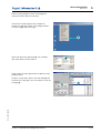
1
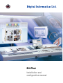
DI-Plot
Installation and
configuration manual
Digital Information Ltd.
Technoparkstrasse 1
CH-8005 Zürich
© Copyright by Digital Information Ltd. 2006
The copyright for this technical documentation remains with Digital Information Ltd.
All rights, including reproduction and distribution rights as well as translation rights, are reserved. No part of the documentation may be
reproduced in any form (printing, photocopying, microfilm or other process) without written per mission, nor may it be stored, processed,
reproduced or distributed using electronic systems.
Every misuse is punishable and requires restitution of damages.
Identifier
Installation and configuration manual - EN
Target group
Administrator
Product
DI-Plot
Version
V5.10
Article code
DI-Plot HB01-009 EN
Table of contents
Table of contents
1
Product Overview ........................................................................................................ 1-1
1.1
What it does..................................................................................................................................... 1-1
1.2
Workflow sample.............................................................................................................................. 1-1
DI-Plot HB01-009 EN
1.3
1.2.1
Input CIP3 – Output JDF with ink coverage ...................................................................... 1-1
1.2.2
Input 1 Bit TIFF – Output on Inkjet LFP Printers ................................................................ 1-2
1.2.3
Input 1 Bit TIFF – Output PDF or TIFF ............................................................................... 1-2
1.2.4
Input 1 Bit TIFF – mixed output as imposition proof, CIP4/JDF, and composite PDF......... 1-3
Using the software ........................................................................................................................... 1-3
1.3.1
Fully automatic mode........................................................................................................ 1-3
1.3.2
Semi-automatic mode ...................................................................................................... 1-4
2
Installation ................................................................................................................ 2-1
2.1
CD content....................................................................................................................................... 2-1
2.2
Software installation ......................................................................................................................... 2-1
2.3
Installing the Dongle Driver ............................................................................................................... 2-4
2.4
Program icons.................................................................................................................................. 2-6
2.5
Default installation path using the Complete setup mode ................................................................. 2-7
2.5.1
Default program directory ................................................................................................. 2-7
2.5.2
Default input path for CIP3 files......................................................................................... 2-7
2.5.3
Default input path for 1 Bit TIFF files.................................................................................. 2-8
2.5.4
Default output path for CIP4/JDF files............................................................................... 2-8
2.6
Multiple Installation ........................................................................................................................... 2-8
3
User Interface............................................................................................................. 3-1
3.1
Short overview ................................................................................................................................. 3-1
3.2
Menu structure................................................................................................................................. 3-1
3.2.1
Semi-automatic or fully automatic mode........................................................................... 3-1
3.2.2
Input and output formats .................................................................................................. 3-2
3.2.3
Timing in Hotfolder mode.................................................................................................. 3-2
3.2.4
Management settings ....................................................................................................... 3-2
3.2.5
Deimposition feature – cut a job into pieces...................................................................... 3-3
3.2.6
Printing feature – defining the printer setup ....................................................................... 3-3
3.2.7
Software information menu ............................................................................................... 3-3
4
Basic Configuration ...................................................................................................... 4-1
4.1
Semi-automatic mode...................................................................................................................... 4-1
4.1.1
Input format settings ......................................................................................................... 4-1
4.1.2
Output format settings ...................................................................................................... 4-3
4.1.3
Size Class concept for Press Templates ........................................................................... 4-4
DI-Plot – Installation and configuration manual
I
Table of contents
4.1.4
Fully automatic Hotfolder mode........................................................................................................ 4-9
4.2.1
Input format settings ......................................................................................................... 4-9
4.2.2
Output format settings ...................................................................................................... 4-9
4.2.3
Timing values in Hotfolder mode..................................................................................... 4-10
5
Advanced Configurations................................................................................................ 5-1
5.1
More input formats........................................................................................................................... 5-1
5.2
Descreening option of the1 Bit TIFF format ...................................................................................... 5-1
5.3
Clipping / Tilling / Deimposing .......................................................................................................... 5-2
5.4
5.5
5.6
II
5.3.1
Box clipping...................................................................................................................... 5-2
5.3.2
Tile clipping....................................................................................................................... 5-3
5.3.3
Deimposing ...................................................................................................................... 5-3
5.3.4
Multi Deimposing .............................................................................................................. 5-5
More output formats ........................................................................................................................ 5-5
5.4.1
CIP3 ................................................................................................................................. 5-5
5.4.2
Creo Virtual Proofing System (VPS)................................................................................... 5-6
5.4.3
DI Printer........................................................................................................................... 5-6
5.4.4
EFI-Fiery ........................................................................................................................... 5-6
5.4.5
EPS .................................................................................................................................. 5-7
5.4.6
Harlequin .......................................................................................................................... 5-7
Impoproof ........................................................................................................................................ 5-7
5.5.1
Inkzones ........................................................................................................................... 5-8
5.5.2
PDF as compressed, uncompressed or greyscale files ..................................................... 5-8
5.5.3
PostScript......................................................................................................................... 5-9
5.5.4
Preproofer 130.................................................................................................................. 5-9
5.5.5
Preproofer Epson............................................................................................................ 5-10
5.5.6
Windows printer driver .................................................................................................... 5-10
5.5.7
RTL Generic.................................................................................................................... 5-11
5.5.8
TIFF as RGB, grayscale and LZW data ........................................................................... 5-11
Management.................................................................................................................................. 5-11
5.6.1
Program name................................................................................................................ 5-12
5.6.2
Program image ............................................................................................................... 5-12
5.6.3
Save and restore the configuration.................................................................................. 5-13
5.6.4
Set the software’s internal directories.............................................................................. 5-14
5.6.5
Color Management settings............................................................................................ 5-14
5.6.6
Select and edit the Spot Color Table............................................................................... 5-14
5.6.7
Select the measuring unit for length ................................................................................ 5-16
5.6.8
Page setups for printer output ........................................................................................ 5-17
DI-Plot – Installation and configuration manual
DI-Plot HB01-009 EN
4.2
Press Template settings .................................................................................................... 4-6
Product Overview
What it does
1
Product Overview
1.1
What it does
1
The software gives productivity a boost in the printing
and prepress trade. A unique set of conversion and
proofing tools can read any file written in 1 Bit TIFF, 8
Bit TIFF, or CIP3/4 format and convert it to the
required output format such as CIP4/JDF, PDF, TIFF
etc.
Next to creating output files in different formats, the
software can also drive most brands of inkjet printers.
These printouts can be used as imposition proofs
with 100% content reliability.
The software can either run in fully automatic
hotfolder mode or in semi-automatic mode.
1.2
Workflow sample
1.2.1
Input CIP3 – Output JDF with ink coverage
When installing the software in the standard setup
routine, the CIP3 to CIP4/JDF workflow is selected by
default:
1
The input format is CIP3, the processed files are
output in CIP4/JDF.
Change the following settings manually:
1) Input folder for CIP3 files
2) Printing press templates
3) Output folder for CIP4/JDF files
1
1
(1) The prepress workflow server creates CIP3 data
(2) Reads CIP3 and calculates the JDF data for the
press
DI-Plot HB01-009 EN
(3) The JDF data is used to ink preset the press
DI-Plot – Installation and configuration manual
1-1
1
1.2.2
Product Overview
Workflow sample
Input 1 Bit TIFF – Output on Inkjet LFP Printers
The workflow server delivers 1 Bit TIFF files for a CTP
or CTF device. The software reads these high
resolution TIFFs and outputs them directly as
imposition proofs on a standard inkjet printer.
1
Change the following settings manually:
1) Input folder for 1 Bit TIFF files
2) 1 Bit TIFF format
3) Windows printer spooler as an output path to the
connected LFP inkjet printer
1
1
4) ICC profiles for Color Management
(1) The prepress workflow server creates 1 Bit TIFF
files for CTP/CTF
(2) Software reads 1 Bit TIFF files and prints
imposition proofs on an inkjet LFP printer
(3) Imposition proof
1.2.3
Input 1 Bit TIFF – Output PDF or TIFF
The software can also create composite PDF/TIFF
files from 1 Bit TIFF data.
1
Change the following settings manually:
1) Input folder for 1 Bit TIFF files
2) 1 Bit TIFF format
3) Output format and output folder
4) ICC profile for Color Management
1
(1) The prepress workflow server creates 1 Bit TIFF
files for CTP/CTF
1
(2) Software reads 1 Bit TIFF files and creates a
composite PDF / TIFF
DI-Plot HB01-009 EN
(3) Composite PDF / TIFF
1-2
DI-Plot – Installation and configuration manual
Product Overview
Using the software
1.2.4
1
Input 1 Bit TIFF – mixed output as imposition proof, CIP4/JDF, and composite PDF
The software translates 1 Bit TIFF files into CIP4/JDF
files. The CIP4/JDF data is used for ink presetting an
offset printing press. Additionally, an imposition proof
on an inkjet LFP printer is produced. For quick
examination, the low resolution PDF can be displayed
on a computer monitor.
1
1
(1) The prepress workflow server creates 1 Bit TIFF
files for CTP/CTF
(2) Software reads 1 Bit TIFF files and creates an
imposition proof, a CIP4/JDF and a composite
PDF
1
1
(3) CIP4/JDF for ink preset the press
(4) PDF
(5) Imposition proof on a LFP printer
1
1.3
Using the software
1.3.1
Fully automatic mode
The software can be configured to run in an
unattended Hotfolder mode. The CIP3 or 1 Bit TIFF
files coming from the prepress workflow server are
dropped into the Hotfolder , from where they get
further processed.
Depending on the configuration, the software will
output in different formats, e.g. CIP4/JDF, TIFF, PDF,
or make a printout on an inkjet LFP printer.
1
DI-Plot HB01-009 EN
The blue bar constantly moving back and forth (1)
indicates that the fully automatic Hotfolder mode is
active.
DI-Plot – Installation and configuration manual
1-3
1
1.3.2
Product Overview
Using the software
Semi-automatic mode
When the software runs in semi-automatic mode,
each job has to be selected manually for conversion
(1). The output format can be CIP4/JDF, TIFF, PDF, or
an imposition proof on an Inkjet Printer.
1
DI-Plot HB01-009 EN
The semi-automatic mode should be chosen for
configuring the software or when running any
functionality tests.
1-4
DI-Plot – Installation and configuration manual
Installation
CD content
2
Installation
2.1
CD content
2
The CD supplied contains the program installer and
several PDF manuals that will assist the user in setting
up and running the software.
2.2
Software installation
Insert the program CD. The AutoStart function
launches the installer. Choose the product to be
installed (1).
1
DI-Plot HB01-009 EN
Choose the language preferred and press [ Next ].
DI-Plot – Installation and configuration manual
2-1
2
Installation
Software installation
Choose [ Next ].
Read the license agreement carefully. To continue
press [ Next ].
DI-Plot HB01-009 EN
Enter the user name and company name and
continue with [ Next ].
2-2
DI-Plot – Installation and configuration manual
Installation
Software installation
2
As setup type choose Complete (1) and continue with
[ Next ].
We recommend running the installer in the
“Complete” mode (1).
Advanced users may prefer the Custom (2) mode for
setup where the available options can be configured
in detail. For instance, the directory for installation can
be selected.
1
1
Choose the appropriate printing press templates for
your installation (1). A template contains the printing
machine’s parameters such as the number of ink
slides per unit, the print size etc.
Press [ Next ] to continue.
1
If you cannot find the template for your press,
continue the setup and select the generic press
template (1) instead.
Note
A generic printing press template can easily be
modified to suit the press’ parameters such as the
number of ink slides, print size etc.
1
DI-Plot HB01-009 EN
Press [ Next ] to continue.
DI-Plot – Installation and configuration manual
2-3
2
Installation
Installing the Dongle Driver
Press [ Next ] to start the installation process.
The software is installed! Click the checkbox (1) if the
driver for the hardware protection dongle should be
installed. This is mandatory if the software is installed
for the first time. Continue with [ Finish ].
1
2.3
Installing the Dongle Driver
If at the end of the installation routine the option
“Install Sentinel dongle driver” is selected, the dongle
driver installer is started.
DI-Plot HB01-009 EN
Continue with [ Next ].
2-4
DI-Plot – Installation and configuration manual
Installation
Installing the Dongle Driver
2
Read the license agreement carefully. To continue
press [ Next ].
As setup type select “Complete” (1) and continue
with [ Next ].
1
DI-Plot HB01-009 EN
Click [ Install ] to begin the installation of the dongle
driver files.
DI-Plot – Installation and configuration manual
2-5
2
Installation
Program icons
The installer will ask if the dongle driver should be
installed in server mode.
Click [ No ] to disable this feature.
1
The dongle driver is installed!
2.4
Program icons
A program shortcut is placed on the desktop and in
the “Start Program” menu (1).
DI-Plot HB01-009 EN
1
2-6
DI-Plot – Installation and configuration manual
Installation
Default installation path using the Complete setup mode
2.5
2
Default installation path using the Complete setup mode
When installing the software in the “Complete” setup
mode (1), the installer creates several directories:
a) a Hotfolder directory for incoming CIP3 or 1 Bit
TIFF files from the prepress server
1
b) an output directory for the converted files
c) a program specific folder containing the
configuration files, temp files etc.
2.5.1
Default program directory
The path to the directory where the program is
installed is shown here (1).
2.5.2
1
Default input path for CIP3 files
1
DI-Plot HB01-009 EN
The default Hotfolder for the CIP3 files coming in from
the prepress workflow system is located here (1).
DI-Plot – Installation and configuration manual
2-7
2
2.5.3
Installation
Multiple Installation
Default input path for 1 Bit TIFF files
The default Hotfolder for the 1 Bit TIFF files coming
from the prepress workflow system is located here
(1).
2.5.4
1
Default output path for CIP4/JDF files
The software outputs the calculated CIP4/JDF files to
a printing press directory (1).
1
As shown in the example on the right, the data
created for a MAN Roland 700 press will be dropped
into its own folder, hence called R700.
During installation, an output folder is created by
default, according to the press machine selected.
This output folder is always installed in the \data
folder.
To change the CIP4/JDF output directory, use the
Inkzone Press Template editor.
2.6
Multiple Installation
DI-Plot HB01-009 EN
The software’s architecture makes it possible to install
the program several times in different directories.
Each of these instances can be configured individually
and run in parallel at the same time.
2-8
DI-Plot – Installation and configuration manual
Installation
Multiple Installation
2
To install an additional instance, run the installer again
and choose the first option (1).
Press [ Next ] to continue.
1
In this window, select the second option (1)
“Costum”.
1
Now you can choose an individual installation
directory (1).
DI-Plot HB01-009 EN
1
DI-Plot – Installation and configuration manual
2-9
User Interface
Short overview
3
User Interface
3.1
Short overview
(1) Title bar of the main window
3
1
(2) Program information image
1
3.2
Menu structure
3.2.1
Semi-automatic or fully automatic mode
Choose from this menu (1) one of these entries (2) to
run the program either in Hotfolder mode or semiautomatic mode.
1
1
To exit the software, choose the last entry (3)
DI-Plot HB01-009 EN
1
DI-Plot – Installation and configuration manual
3-1
3
3.2.2
User Interface
Menu structure
Input and output formats
Open this menu (1) to configure the input and output
formats for manual conversion mode (2) or for
Hotfolder conversion mode (3).
1
1
1
3.2.3
Timing in Hotfolder mode
Timing in Hotfolder mode is set by selecting this entry
(2) from this menu (1).
1
1
3.2.4
Management settings
Open this menu (1) for configuring the directories for
temp files, log files etc. (2).
Select the other entries when some of the additional
configurations should be adjusted, such as changing
the program name, editing the spot color table, or
setting the unit of length.
1
1
DI-Plot HB01-009 EN
Save the current configuration to the archive for later
restoration (3).
1
3-2
DI-Plot – Installation and configuration manual
User Interface
3
Menu structure
3.2.5
Deimposition feature – cut a job into pieces
Through this menu (1) the deimposition templates can
be defined.
1
The deimposing feature splits a large size job into
multiple smaller pages, which can be output on a
smaller printer.
3.2.6
Printing feature – defining the printer setup
Through this menu (1) configurations for different
inkjet printers can be defined. Use this feature for
proofing 1 Bit or 8 Bit TIFF files on an Inkjet printer.
3.2.7
1
Software information menu
1
DI-Plot HB01-009 EN
This menu (1) informs which version of the software is
currently installed.
DI-Plot – Installation and configuration manual
3-3
Basic Configuration
Semi-automatic mode
4
Basic Configuration
4.1
Semi-automatic mode
For configuring the semi-automatic mode’s settings
open this menu (1) and select the first entry (2).
4
1
1
4.1.1
Input format settings
For processing CIP3 files coming in from the prepress
workflow system, set the input format to CIP3, which
is the standard setup after installation. To change the
input format open the list box here (1). All available
input formats will show up.
1
1
Select the input folder by clicking on the directory
path (2).
A new dialog window will pop up (3). Select the input
path here (4).
1
DI-Plot HB01-009 EN
1
DI-Plot – Installation and configuration manual
4-1
4
Basic Configuration
Semi-automatic mode
CIP3 files which were mirrored or were created as
negatives can be processed by selecting these check
boxes (1) (2).
1
In some rare cases, a CIP3 needs to be scaled up or
down to increase or decrease the output format.
Enter a value above 100% for increasing, or a value
below 100% for decreasing.
1
1
1
The percentage set in the X field scales the horizontal
dimension (3), the percentage set in the Y field the
vertical dimension (4).
Clicking on this button (1) will open a new dialog
window (2).
1
These buttons determine the way in which the files
are treated after processing:
1
• No action (3) will be taken.
1
• Input jobs will be deleted after conversion (4).
1
• Converted jobs will be moved to the “Completed”
folder (5)
The left panel of the dialog box refers to successful
conversions; the right panel to conversions where an
error has occurred.
1
Note
The ”Completed” folder can be selected from the
“Management” menu.
1
4-2
DI-Plot – Installation and configuration manual
DI-Plot HB01-009 EN
This field (1) sets the interval, in seconds, in which the
input folder is refreshed. A valid setting is between 1
to 999 seconds.
Basic Configuration
Semi-automatic mode
4
In some rare cases, a CIP3 file will not comply by
100% with the specifications set by the CIP3/4
organization. The software cannot process such files.
There is a possible workaround: change the setting in
this list box (1) and try processing the file again.
1
4.1.2
Output format settings
CIP4/JDF is the software’s standard output format. It
is used for ink presettings on an offset printing press.
1
Open this list box to select another output format by
clicking on the arrow facing down (1).
1
An HTML path can be chosen here (2). It is used for
preview images in a client server environment.
Note
The standard URL is valid in most cases.
This value (1) sets the output file’s resolution. The
standard setting of 50 will fit most cases.
These three check boxes (2) activate following
functions (from top to bottom):
1) Creates a JDF file containing ink key coverage
data. The ink key coverage is calculated from a
specific set of press machine parameters.
2) Creates a preview PNG file.
1
1
DI-Plot HB01-009 EN
3) Adds the input job’s RGB color plane values to the
JDF file.
DI-Plot – Installation and configuration manual
4-3
4
Basic Configuration
Semi-automatic mode
Activate this checkbox (1) to create JDF files
containing a front and back side.
Spot colors are emulated by CMYK values listed in
the Spot Color Table. This list box (2) selects the
software’s reaction when spot colors required by a job
are missing. Choose between two settings:
(1) The first setting (2) stops the conversion and alerts
the user to the spot colors missing.
1
(2) The second setting continues the conversion and
replaces the missing spot colors by the Default Color
defined in the Spot Color Table.
1
Details on using the spot color table see Chapter 3 of
the User Manual.
Press this button (1) to select a Press Template.
1
4.1.3
Size Class concept for Press Templates
The Size Class concept helps processing CIP3 files
differing in dimension.
An individual Press Template can be chosen for each
Size Class (1).
CIP3 files being sent to the input folder, for example,
could be scaled to 1040 x 790 mm for a large format
press, to 740 x 605 mm for a medium format press,
and to 520 x 400 mm for a small format press.
1
1
1
Depending on the Press Template, the software will
calculate the job’s dimension either from its height or
from its width.
DI-Plot HB01-009 EN
With the list box (2) the size trigger can be set on job
height or width.
The settings for the example mentioned above would
look like this for the large format press (3), like this for
4-4
DI-Plot – Installation and configuration manual
Basic Configuration
Semi-automatic mode
4
the medium format press (4), and like this for the
small format press (5).
This template (3) will convert any CIP3 files wider than
1039 mm.
1
1040 x 790
This template (4) will convert any CIP3 files between
739 mm and 1039 mm in width.
1
740 x 605
This template (5) will convert any CIP3 files between 0
mm and 739 mm in width.
1
520 x 400
DI-Plot HB01-009 EN
Note
If the software needs to support only one press
format, select the correct Press Template and set this
parameter (6) to 200. The result will be that any CIP3
files wider than 200 mm will be converted according
to the Inkzone Press Template selected.
DI-Plot – Installation and configuration manual
4-5
4
4.1.4
Basic Configuration
Semi-automatic mode
Press Template settings
Open the press template editor with these button (1).
1
Select the appropriate Press Template settings here:
1
(1) Name of the Inkzone Press Template
1
1
(2) Output path for the calculated ink coverage data,
as JDF or *.ink files, and the preview images
generated from them
1
1
(3) Size class indicator
(4) Opens an existing Inkzone Press Template
(5) Stores the current Inkzone Press Template
An Inkzone Press Template defines all the parameters
necessary for calculating a job’s ink coverage and
sets the ink keys on the offset press accordingly.
Specify a template by the settings in this window:
(1) Number of ink zones
(2) Zone width
(3) Zone width of the first and last key. In some rare
cases their values may differ from those entered here
(2)
1
1
1
1
(4) This value is calculated automatically by
multiplying the number of ink zones by their width:
DI-Plot HB01-009 EN
(1) x (2) = (4)
4-6
DI-Plot – Installation and configuration manual
Basic Configuration
4
Semi-automatic mode
Example 1
1
(1) = 24
(2) = 30 mm
1
1
1
24 x 30 = 720 mm
If the first and last key differ, the formula looks like
this:
((1) -2) x (2) + (3) + (3) = (4)
Example 2
(1) = 34
(2) = 30 mm
(3) = 25 mm
(34-2) x 30 + 25 + 25 = 1010 mm
(3) Maximum sheet length plus a value for a bitmap
shift on the Y axis
(2) Bitmap shift on the Y axis (defines where printing
starts)
1
(4) Output job orientation. Click once on this icon to
rotate it by 90 degrees and to mirror it. The selected
orientation and mirroring are applied before
calculation starts.
1
1
(5) Position of the calculated bitmap in relation to the
inkzone area. In some rare cases the position may
differ from the example shown in the screenshot
underneath.
1
1
DI-Plot HB01-009 EN
1
1
DI-Plot – Installation and configuration manual
4-7
4
Basic Configuration
Semi-automatic mode
(1) Bitmap shift in on horizontal x axis . In some rare
cases this value could deviate from 0, e.g. if the
plates are not center mounted in relation to the ink
keys on the press.
(2) Ink coverage is calculated according to the zone
width selected here. Differing values for the first and
last key are taken into account. In some rare cases
the second entry has to be selected.
1
(3) Measuring unit for the preview image’s resolution,
either pixels or dpi can be selected.
1
1
1
(4) Size of the preview image according to the
measuring unit selected (3)
(1) Ink coverage is calculated according the setting
selected here. Either the inkzone area’s length or the
job’s bitmap length is taken into account. In some
rare cases the second entry has to be selected.
(2) In standard mode, the calculated preview image
and the calculated ink coverage file are oriented in the
same dimension.
1
If necessary, the preview image can be orientated in a
different dimension than the calculated ink coverage
data. Click on this button (2) to change it.
1
1
For creating a preview image with another orientation
than the calculated ink coverage file, press this button
(3).
If the Bitmap Area is selected by this button (3), the
orientation of the preview image (5) and the
calculated inkzone file (4) can be selected individually.
1
1
DI-Plot HB01-009 EN
1
4-8
DI-Plot – Installation and configuration manual
Basic Configuration
Fully automatic Hotfolder mode
4.2
Fully automatic Hotfolder mode
The automatic Hotfolder settings can be accessed by
opening this menu (1) and selecting the second entry
(2).
4.2.1
4
1
1
Input format settings
All input format settings in automatic Hotfolder mode
are identical to those in semi-automatic mode. An
exception is this check box (1). If activated, the subdirectories on the input path (2) are scanned
automatically.
1
1
4.2.2
Output format settings
All output format settings in automatic Hotfolder
mode are identical to those in semi-automatic mode.
An exception is this setting (1). It causes that
unknown spot colors will be replaced by the Default
Color. Its values are defined in the Spot Color Table.
For further information see chapter 3 of the User
Manual.
DI-Plot HB01-009 EN
1
DI-Plot – Installation and configuration manual
4-9
4
4.2.3
Basic Configuration
Fully automatic Hotfolder mode
Timing values in Hotfolder mode
For configuring the automatic Hotfolder settings open
the third entry (1) from this menu (2).
1
1
Time management in Hotfolder mode ensures a
stable file conversion. Its setup depends on the
prepress workflow server’s speed and throughput.
All files loaded into the Hotfolder will be checked on
their creation time and date.
The following configurations can be accessed:
(1) System time provided by the PC workstation.
1
(2) Interval start time for the Hotfolder files. All
incoming files younger than the time and date set in
these fields will be processed. Change date and time
manually by clicking on the up or down buttons.
1
1
1
1
1
(3) This button sets the interval’s start time and date
to the current system time
(4) Resets the interval start date to 1.1.1998
(5) Resets the interval start time to 0:00
(6) Select either button for storing or rejecting the
current settings.
(1) Stabilizing time: waiting period before the software
starts processing a job.
1
1
Aspect of CIP3 Input
CIP3 input: after the prepress workflow server has
created a CIP3 file and has transferred it completely
to the Hotfolder directory, the software waits for an
additional period of time entered here (1) until it starts
the conversion.
DI-Plot HB01-009 EN
Aspects of 1 Bit TIFF Input
When a job is written to the Hotfolder directory and
one of its color separations has just arrived, the
software waits for a period of time which is selected
4-10
DI-Plot – Installation and configuration manual
Basic Configuration
Fully automatic Hotfolder mode
4
here (1). If no further separation comes in during that
time (1), the job is stable. The software treats it as
being complete and begins the conversion.
DI-Plot HB01-009 EN
With this check box enabled (2), the software regards
the current job file as being complete when an entirely
new job is available in the Hotfolder directory.
DI-Plot – Installation and configuration manual
4-11
Advanced Configurations
More input formats
5
Advanced Configurations
5.1
More input formats
The software can process all common input formats
(1). Next to CIP3, the software accepts 1 Bit or 8 Bit
TIFF files in all their variations. Additionally, the
software can be fed with HP-RTL and Epson ESC/2
printer code.
5
1
Detailed specifications on all the compatible formats
can be found in “Supported Input Formats.pdf”, a
manual included with this software.
5.2
Descreening option of the1 Bit TIFF format
When high resolution 1 Bit TIFF files are processed,
the source data is descreened for output.
Depending on speed and quality demands, the
output quality can be set accordingly. Click the button
here (1) to open the window for setting the quality.
1
1
For speed select the standard setting here (2).
DI-Plot HB01-009 EN
1
For high quality requirements select this screen here
(3) and choose a setting between 1 and 6.
1
Degree 1: sharp dots giving the highest definition
Degree 6: maximum softening applied
DI-Plot – Installation and configuration manual
5-1
5
5.3
Advanced Configurations
Clipping / Tilling / Deimposing
Clipping / Tilling / Deimposing
Crop a job with this function, or split it into multiple
tiles. The deimposition function cuts a large job into
smaller pages which can then be output on a smaller
printer. Select the required function here (1).
1
5.3.1
Box clipping
Select and activate the function here (1).
Set the X/Y starting point on axes X and Y here (2)
and enter the clip box’ size by length (3) and width
(4).
1
1
1
1
1
1
5-2
DI-Plot – Installation and configuration manual
DI-Plot HB01-009 EN
1
Advanced Configurations
5
Clipping / Tilling / Deimposing
5.3.2
Tile clipping
(1) Select and activate the function here.
Set the tiles’ length and width (2) and their overlap
(3).
1
1
1
1
1
1
1
1
5.3.3
1
1
1
Deimposing
(1) Select and activate the function here.
Choose the required scheme here (2).
DI-Plot HB01-009 EN
1
1
DI-Plot – Installation and configuration manual
5-3
5
Advanced Configurations
Clipping / Tilling / Deimposing
A deimposing scheme can be modified by selecting
this menu (3).
1
A control panel will open.
Choose a name for the scheme and type it in here (1).
1
1
1
Enter the parameters of the clip boxes here (2):
the starting point on axes X and Y here (3), the length
and width of the boxes here (4).
1
DI-Plot HB01-009 EN
To deimpose an 8 up job, set up eight clip boxes as
shown in the example on the right. These boxes are
marked by cyan lines.
5-4
DI-Plot – Installation and configuration manual
Advanced Configurations
5
More output formats
5.3.4
Multi Deimposing
Select and activate the function here (1).
Select a size class here (2), small, medium, or large.
The concept of page size classes (3) is identical to
the chapter “Size Class concept for Press Templates”.
1
1
1
5.4
More output formats
The software can output in many differing data
formats which can be selected here (1).
1
5.4.1
CIP3
CIP3 output of 1 Bit TIFF files:
The resolution is selected here (1).
When this check box (2) is activated, the CIP3 files
contain both a front and back side.
The file’s orientation can be changed by clicking on
this button (3).
1
1
DI-Plot HB01-009 EN
1
DI-Plot – Installation and configuration manual
5-5
5
5.4.2
Advanced Configurations
More output formats
Creo Virtual Proofing System (VPS)
Output as Creo VPS files that can be viewed by
Creo’s VPS client software. The VPS system’s task is
to proof files on a monitor that have already been
ripped.
1
Select the resolution here (1).
1
1
Click this check box (2) to use the input file’s
resolution for output. No down-sampling is applied,
the resolution setting (1) is overridden.
1
Click this check box (3) to output the data separated.
Select from this list box (4) an additional output
format. This file is produced during conversion.
5.4.3
DI Printer
Output to a fast black and white A3+ printer.
Select the resolution here (1).
1
Click this check box (2) to use the input file’s
resolution for output. No down-sampling is applied,
the resolution setting (1) is overridden.
1
1
Click this check box (3) to output the data separated.
1
Select from this list box (4) an additional output
format. This file is produced during conversion.
5.4.4
EFI-Fiery
Output to EFI Fiery RIP which is usually connected to
a Laser Copier system.
1
Select the resolution here (1).
Click this check box (2) to use the input file’s
resolution for output. No down-sampling is applied,
the resolution setting (1) is overridden.
Click this check box (3) to output the data separated.
Select from this list box (4) an additional output
format. This file is produced during conversion.
1
1
1
1
1
1
1
Select the Windows printer queue (5) to which the
Fiery RIP is connected through TCP/IP.
DI-Plot HB01-009 EN
Select from three paper sizes (6) that can be used in
the Copier system.
Rotate the input job by 90 degrees clockwise (7).
Click this check box (8) to add a header to the print
job, containing its name, time and date, its size, and a
5-6
DI-Plot – Installation and configuration manual
Advanced Configurations
Impoproof
5
freely selectable user identification code. Activate the
check box (9) to draw a frame line around the job.
5.4.5
EPS
Output as an EPS file. The bitmapped job is
converted and integrated into an EPS header.
Select the resolution here (1).
1
Click this check box (2) to use the input file’s
resolution for output. No down-sampling is applied,
the resolution setting (1) is overridden.
1
1
1
Click this check box (3) to output the data separated.
1
Select from this list box (4) an additional output
format. This file is produced during conversion.
Switch encoding to ASCII (5) instead of Binary.
5.4.6
Harlequin
Output to a Harlequin RIP.
Select the resolution here (1).
Click this check box (2) to use the input file’s
resolution for output. No down-sampling is applied,
the resolution setting (1) is overridden.
1
1
1
Click this check box (3) to output the data separated.
Select from this list box (4) an additional output
format. This file is produced during conversion.
1
1
Select one or all colors for processing (5).
5.5
Impoproof
Output to an Impoproof system, a double sided
imposition proof system.
Select the resolution here (1).
1
1
(2) Create output job for front and back
DI-Plot HB01-009 EN
When this check box (2) is activated, the files contain
both a front and back side.
Activate this check box (3) to draw a frame line
around the job.
1
1
1
Select from this list box (4) an additional output
format. This file is produced during conversion.
Select one or all colors for processing (5).
DI-Plot – Installation and configuration manual
5-7
5
5.5.1
Advanced Configurations
Impoproof
Inkzones
Output in *.ink format including the corresponding
preview file in bmp format. The settings are identical
to those described for CIP4/JDF output (see section
4.1.2).
Additional settings:
(1) Used to connect a MS-DOS based system. The
files are named according to the 8.3 name
convention, e.g. abcdefgh.ink
1
1
1
1
(2) Abbreviates long spot color names, e.g. to S1, S2,
etc.
(3) Creates an inkzone data file.
(4) Creates a bmp file for preview.
5.5.2
PDF as compressed, uncompressed or greyscale files
Output as a PDF. The PDF data can either be created
with or without compression or in grayscale mode.
The bitmapped job is converted and integrated into a
PDF header.
Select the resolution (1).
The file’s input resolution is used for output (2). No
down-sampling is applied, the resolution setting (1) is
overridden.
1
1
1
1
1
1
1
1
Click this check box (3) to output the data separated.
Select from this list box (4) an additional output
format. This file is produced during conversion.
Rotate the input job by 90 degrees clock wise (5).
Click this check box (6) to add a header to the print
job, containing its name, time and date, its size, and a
freely selectable user identification code. Activate the
check box (8) to draw a frame line around the job.
DI-Plot HB01-009 EN
Select one or all colors (7) for processing.
5-8
DI-Plot – Installation and configuration manual
Advanced Configurations
Impoproof
5.5.3
5
PostScript
Output as a PostScript file. The bitmap job is
transferred to an image and wrapped into a PS
header.
1
Select the resolution here (1).
Click this check box (2) to use the input file’s
resolution for output. No down-sampling is applied,
the resolution setting (1) is overridden.
1
1
1
Click this check box (3) to add a header to the print
job, containing its name, time and date, its size, and a
freely selectable user identification code. Activate the
check box in the lower section to draw a frame line
around the job.
Select from this list box (4) an additional output
format. This file is produced during conversion.
5.5.4
Preproofer 130
Output to Preproofer130, a double-sided imposition
proof system.
Select the resolution here (1).
Select the Windows printer queues (2) for the front
and back side printers.
Activate this check box (3) to draw a frame line
around the job
1
1
1
1
1
1
Select from this list box (4) an additional output
format. This file is produced during conversion.
Select one or all colors for processing (5).
DI-Plot HB01-009 EN
Click this check box (6) for producing files containing
both a front and back side.
DI-Plot – Installation and configuration manual
5-9
5
5.5.5
Advanced Configurations
Impoproof
Preproofer Epson
Output for the Preproofers based on Epson printers
for double-sided imposition proof printing.
Select the resolution (1).
1
Select the conversion mod (2). Supported is standard
mode or master/slave mode. In master/slave mode, a
second instance of the program is used to convert
the back side, triggered by the Master instance. This
allows to convert the front and back sides in parallel.
1
1
1
1
1
Click this check box (3) to draw a frame line around
the job.
Select from this list box (4) an additional output
format. This file is produced during conversion.
Select one or all colors for processing (5).
Click this check box (6) for producing files containing
both a front and back side.
5.5.6
Windows printer driver
Output on printers, using a Windows printer driver.
Install the printer driver first, and then select the
Windows queue for output.
1
Select the resolution (1).
1
Activate the check box to add a header on the print
job, containing job name, time and date, job size and
a free definable user identification. Activate the check
box in the lower section to add a border line around
the job dimension
1
1
Click this check box (2) to add a header to the print
job, containing its name, time and date, its size, and a
freely selectable user identification code. Click this
check box (3) to draw a frame line around the job.
Select from this list box (4) an additional output
format. This file is produced during conversion.
Select one or all colors for processing (5).
Click this check box (6) to select the printer
automatically, depending on the job name marker.
1
1
1
1
1
Set an offset on axes X and Y (7) to move the bitmap.
Click this check box (8) to output the data separated.
5-10
DI-Plot HB01-009 EN
Switch encoding to ASCII (9) instead of Binary when
using a PostScript printer.
DI-Plot – Installation and configuration manual
Advanced Configurations
5
Management
5.5.7
RTL Generic
Output for printers accepting HP-RTL code.
Select the resolution (1).
(2) Select the job alignment, left, middle or right.
1
1
(3) Enable for double sided imposition system driven
by HP-RTL code.
1
1
(4) Additionally to the output format, a second output
format can be produced at the same time of
converting the data.
1
1
(5) Select one or all colors to process.
(6) Add a border line around the job dimension.
5.5.8
TIFF as RGB, grayscale and LZW data
Output to TIFF files. They can be created with or
without LZW compression and either in RGB or
grayscale mode.
1
Select the resolution (1)
1
The file’s input resolution is used for output (2). No
down-sampling is applied, the resolution setting (1) is
overridden.
1
1
1
1
Activate this check box (3) to draw a frame line
around the job.
Select from this list box (4) an additional output
format. This file is produced during conversion.
Select one or all colors for processing (5).
Click this check box (6) to output the data separated.
5.6
Management
Some of the program’s internal settings can be
selected in this menu (1).
1
DI-Plot HB01-009 EN
Configure parameters such as Program Name, Edit
Spot Color Table, or the measuring unit of length. The
current configuration can be saved in the archive for
restoration.
DI-Plot – Installation and configuration manual
5-11
5
5.6.1
Advanced Configurations
Management
Program name
Select this item (1).
1
When setting up multiple installations of the program,
it’s useful to give each instance a distinctive name.
Enter a name here, it will appear in the program’s title
bar.
5.6.2
Program image
1
DI-Plot HB01-009 EN
Turn on/off the program’s start-up screen which is
displayed during its launch (1).
5-12
DI-Plot – Installation and configuration manual
Advanced Configurations
Management
5.6.3
5
Save and restore the configuration
The current configuration can be saved to the archive
here (1), or a previous configuration can be restored
from it.
1
Select (1) and choose a destination file and folder (2)
for the archive.
1
Select the Restore item from the menu to load a
backup file (3) for restoring a saved configuration.
DI-Plot HB01-009 EN
1
DI-Plot – Installation and configuration manual
5-13
5
5.6.4
Advanced Configurations
Management
Set the software’s internal directories
Temporary files: they are created when an input file is
processed.
Completed files: this is the directory where input files
are moved to after processing. How the files are
treated afer processing can be selected in the setup
window (see chapter 4.1.1).
1
Error files: the directory where error files are moved to
after a conversion has failed. This option can be
selected in the setup window (see chapter 4.1.1).
Log files: they are stored here. The log level is
selected by entering a number in the first line of the
file called VrbLevel.txt. Default value is 0, which
means no log file is created. The maximum log level
value is 100.
5.6.5
Color Management settings
Setup of Color Management (CMM) based on ICC
profiles (1). Color Management controls the output of
processed files and the data sent to printers.
1
Select a press reference profile (2) such as
isocoated.icm.
If the output is set to Printer, select the ICC profile (3)
for Windows printers. Activate Color Management by
clicking on its checkbox (4).
For all other output, choose an appropriate ICC profile
(5).
1
1
1
1
1
5.6.6
DI-Plot HB01-009 EN
Activate Color Management by clicking on its check
box (6).
Select and edit the Spot Color Table
In this table, the CMYK values for each spot color are
stored. There are over 8000 shades defined already.
5-14
DI-Plot – Installation and configuration manual
Advanced Configurations
Management
5
When running multiple instances of the program,
select one central table for all of them.
Chose from the menu (1) the item to open the
window for selecting a table. A new dialog windows
will come up (2). See next image.
1
Select the spot color table here (2). The standard
spot color table is called “color.txt”
1
Choose from the menu (1) the item to open the color
editing window.
1
To adjust a spot color, select it from the table (3) and
enter the new values (4). Press this button to save the
changes (5).
1
DI-Plot HB01-009 EN
1
DI-Plot – Installation and configuration manual
5-15
5
Advanced Configurations
Management
To add a new color, type its name here (7) and enter
the CMYK values. Press this button (6) to store them.
1
To delete a color entry, select it and press this button
(8).
5.6.7
1
1
Select the measuring unit for length
The measuring unit of length (1) can either be set to
metric or inches.
DI-Plot HB01-009 EN
1
5-16
DI-Plot – Installation and configuration manual
Advanced Configurations
Management
5.6.8
5
Page setups for printer output
1
DI-Plot HB01-009 EN
Choose from this menu (1) the page setups for the
printer systems supported by the program.
DI-Plot – Installation and configuration manual
5-17