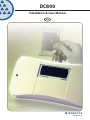
1
DC800 Installation & User Manual EN Copyright © 2006 Bewator AB, Solna. Material from this manual may only be copied with the consent in writing of Bewator. Bewator reserves the right to alter both the content of the manual and the design of the product. Document number: 81473-5 Bewator AB develops and markets a complete security product enter that includes access control and alarm. Sales, installation and servicing are handled by a national dealer network. Actions (such as unauthorised manipulation, copying etc.) must not be taken with the software contained in the products and systems. Such actions are regarded as copyright violation and may result in imprisonment or fines and may likewise lead to an obligation to pay damages and compensation for using the software. DC800 Installation & User Manual Content What is the DC800?......................................................................... 5 Features included in the DC800?.................................................................... 5 Documenting the programming...................................................................... 5 Using non Bewator cards for entrance............................................................6 How does the DC800 work?.............................................................. 7 Security levels................................................................................................ 7 Examples of timing security levels ................................................................. 7 Time zones and day types...............................................................................8 Time schedules..............................................................................................9 Anti-passback................................................................................................9 Installing the DC800...................................................................... 10 Installing the BC43/BC43Prox/BC43EM readers............................................ 10 Installing other type of readers..................................................................... 10 Dimensioning the cables...............................................................................11 Recommended cables...................................................................................11 Wiring.......................................................................................................... 12 Using cable glands...................................................................................... 14 Programming..................................................................................15 Buzzer and LEDs........................................................................................... 15 Set DC800 to programming mode................................................................ 15 Set time and date......................................................................................... 15 Changing the password............................................................................... 16 Program time zones..................................................................................... 16 Erase a time zone......................................................................................... 16 Program time schedules............................................................................... 17 Erase a time schedule.................................................................................. 17 Program holidays......................................................................................... 17 Delete individual holidays............................................................................ 17 Delete all holidays........................................................................................ 18 Programme/change/erase group code......................................................... 18 Set time schedule “Door unlocked”.............................................................. 19 Set time schedule “Group code”................................................................... 19 Set time schedule “Card Only”...................................................................... 19 Set time schedule “Card + PIN”.................................................................... 19 Set time schedule “Toggle”.......................................................................... 19 Log on a card (with a card)...........................................................................20 Log on a card (without the card)...................................................................20 Log on a series of cards................................................................................20 Cancel card (with card)................................................................................. 21 Cancel card (without card)............................................................................ 21 Bank Lobby Function.................................................................................... 21 DC800 Installation & User Manual Special settings............................................................................. 22 Card reading parameters..............................................................................22 Set door release time...................................................................................22 Set door held warning time..........................................................................22 Buzzer ON/OFF.............................................................................................23 Door monitor contacts ON/OFF.....................................................................23 Function for extra relay.................................................................................24 Anti-passback.............................................................................................. 25 Calculated PIN.............................................................................................. 25 Programming barring.................................................................................. 25 Erase the memory.......................................................................... 26 Factory settings............................................................................................26 Programming overview...................................................................27 Daily use........................................................................................31 Choose/change PIN code............................................................................. 31 Duress......................................................................................................... 31 Troubleshooting............................................................................. 32 Technical specification................................................................... 33 Charts............................................................................................ 34 DC800 Installation & User Manual What is the DC800? DC800 a reader controller designed for one door. It has a capacity of storing up to 1000 cards. Card readers for both entry and exit can be connected (BCLINK). The DC800 can also be included in a larger systems consisting of several card reader controllers. • Stand-Alone. Programming is done on the DC800’s or the card reader’s keypad. • As a component in a small system. Programming is done via a connected PC with the Entro Lite software installed and a USB‑RIF/2 interface. Up to eight DC800 can be con‑ nected. Information about the installation and how to use it is explained in the sepa‑ rate documentation supplied with the software. • As a component in a large system. Programming is done via a connected PC with the Bewator Entro software installed and a Segment Controller to control the DC800. Note! This handbook describes only how the DC800 is installed and programmed in a Stand-Alone mode. Features included in the DC800? • Different reader type. DC800 can be connected to BCLINK, CLOCK & DATA as well as Wiegan26-bit, Wiegand32-bit and Wiegand 8-bit PIN code readers. • Bank Lobby Function. It is possible to use one or several types of cards, e.g. American Express or Visa. This operates using prefixes (see section Bank Lobby Function). • Five different security levels. Various methods of opening the door, e.g. Card only, Card + PIN and Group code. • Built-in time clock. Enables time control of cards and security levels. Holidays, half‑days and holiday periods can be pre-programmed. • Door Monitoring. Enables activation of an alarm if the door is forced open or held open too long. A duress function is integrated (to protect an User from threats from an intruder). • Anti-passback. An entry access must be followed by an exit access with the same card. Requires two BCLINK readers. • Automatic adjustment of clock for daylight saving. According to European standard (last Sunday in March and October). Documenting the programming When the DC800 is used as a stand-alone unit is it very important that any changes of e.g. time schedules and a card parameters is continuously logged manually due to the fact that no printout can be done (no RS232 interface available). Note! If instead the Entro Lite software and a PC is used, the information and events can be printed on the PC’s normal printer. DC800 Installation & User Manual Using non Bewator cards for entrance In DC800 mag stripe cards of different types, e.g. credit cards or some organisation’s special card can be used for access. This is possible by programming the card’s prefix in the DC800. It is possible to combine the use of these cards with the “normal” cards pro‑ grammed via the standard procedures. Note! Because all positions have to be read (and then evaluated) the reader MUST be of type Clock & Data and reading mag stripe card. E g BC18 or BC16 (UK only). Example 1 - Cards with exact prefix: The card number is 5760 0096 0029 5679. The four first digits – the prefix – identifies the card as a certain bank’s card. Example 2 - Cards with some wild card digits When programming a prefix, a digit in the prefix can be substituted for a ”wild card”. Any digit may occur in the wild card’s place to make the card valid. If a prefix is programmed as 1257*0, cards using the prefixes 125700, 125710, 125720, 125730, 125740, 125750, 125760, 125770, 125780 and 125790 will be valid. In DC800, 15 prefixes can be programmed. Each prefix may consist of maximum 7 digits. The first digit in the prefix may begin at any position on the card. Information about pre‑ fixes on different cards can be obtained from the bank or company supplying the card. You may also contact Bewator for advice. For information on how to activate Bank Lobby Function, read the Bank Lobby Function chapter (see Table of contents). Note! If Bank Lobby Function is enabled, the security level always have to be Card only, otherwise the card will not work. DC800 Installation & User Manual How does the DC800 work? DC800 can easily be adapted to the security requirements in a particular building, a par‑ ticular day of the week or time of day. To make this possible you have to be familiar with the following concepts: • Security levels • Time zones • Day types • Time schedules • Anti-passback Security levels The security level determines what action is required to unlock the door. The following security levels exist: • Unlocked door. Neither cards nor codes are needed to unlock the door (free access) • Group code. A four-digit code (same code for all users) is required to unlock the door. • Card only. The user must use their card to open the door. • Card + PIN. The user must use their card and enter a personal code (PIN) to unlock the door. • Toggle function. Used together with current security level, i.e. Card only, Group code or Card + PIN. Every second time the card or code is used the door is opened. The door remains unlocked until the card/code is used the next time or until another security level starts by a time schedule. Examples of timing security levels During office hours, when there are people in the premises, the security level may not need to be high: Unlocked door or Group code may be suitable levels. During lunchtime, the level may be raised to Card only. The remaining time, i.e. eve‑ nings, nights and weekends Card + PIN is a suitable security level. The Toggle function can be used in premises where a person is responsible during cer‑ tain hours; e.g. a classroom or a loading bay door. In a classroom, the teacher can open the door, which remains open until he or she locks the door. The pupils may come in and out without having cards or group code. Note! DC800 has by default the security level Group code with time schedule 01 tied to time zone 01 (00:00 - 23:59, all days). This means that if a group code is pro‑ grammed (command A21), it will be valid 24 hours a day. A valid card can then also be used in parallel. Overlapping security levels Remember that if you unintentionally program overlapping time schedules (used for the security levels) the highest security level apply in the following order: Closed Door, Card+PIN, Card only, Group code and Unlocked. E g if Card only is using time schedule 08:00-16:59 but Card+PIN is using time schedule 12:00-12:59, Card+PIN will be overriding due to higher priority. DC800 Installation & User Manual Time zones and day types There are two purposes of creating time zones: • To be able to assign different security levels to different times of the day. • To be able to make certain cards valid at certain times. Example: The working hours in an office could be as follows: Monday to Friday: 08.30-11.59 and 13.00-17.59 Lunch: 12.00-12.59 Saturdays, Sundays and holidays: Closed Holidays, e.g. the day before Christmas: 08.30-11.59 and 13.00-14.59 To make the reader controller understand that holidays, e.g. Christmas Eve and holiday periods, should not be treated as ordinary working days, this information must be pro‑ grammed. Note! A time zone is valid from and including the first second in the first minute up to and including the last second in the last minute. So a 24 hour day is programmed as 00:00 – 23:59. The day type determines what day of the week the time zone applies. 1 = Monday, 2 = Tuesday etc. 8 is an extra day type that can be used for holidays, e.g. the day before Christmas. Each time zone may consist of two intervals. To be able to assign suitable security levels to the office example above, the following time zones are needed: Time zone no 01 Applies Applies 24 hours a day (all day types). Note: Default time zone that can be changed. See on next page. 02 08.30 – 11.59 and 13.00 – 17.59 Monday to Friday (day types 1, 2, 3, 4 and 5). See on next page. 03 During lunch 12.00 – 12.59 Monday to Friday and half-days (day types 1, 2, 3, 4, 5 and 8). See on next page. 04 In the evening & night-time 00.00 – 08.29 and 18.00 – 23.59 Monday to Friday (day types 1, 2, 3, 4 and 5). See on next page. 05 On Saturdays and Sundays 00.00 – 23.59 (day types 6 and 7). See on next page. 06 During working hours 08.30 – 11.59 and 13.00 – 14.59 on half-days (day type 8). See on next page. 07 In the night-time 00.00 – 08.29 and 15.00 – 23.59 on half-days (day type 8). See on next page. Up to 80 different time zones can be created. You may for example define a specific time zone for the cleaning staff: 08 Applies between 06.00 and 07.59 (day types 1 and 3). DC800 Installation & User Manual 00:00 06:00 12:00 Mon - Sun Sat- Sun Holidays 23:59 Mon - Fri 18:00 Time schedules There are two purposes for creating time schedules: • To be able to combine time zones, into the same time schedule, for an easier control of security levels. • To be able to combine time zones defined for the time control of specific cards. When the desired time schedules have been defined, it is an easy task to tie them either to a certain security level or to specific cards . Up to 10 different time schedules with each eight time zones can be created. This example shows how to include time zones into time schedules (the time zones defined in the previous example are used).. Time schedule no Includes time zone/s 01 01 (enabling assignment of time zone 01 to the cards). Note: Default time schedule that can be changed 02 02 and 06 (enabling the ”Group code” security level to be assigned to both time zones). 03 03 (enabling assignment of the ”Card only” security level to the lunch hour). 04 04, 05 and 07 (enabling assignment of the ”Card + PIN” security level to evenings, nights, weekends and holidays). 05 08 (enabling assignment of time zone 08 to the cleaning staff’s cards). Anti-passback Anti-pass-back is way to increase the security even further. Anti-passback simply means that a card holder may not enter through a door twice unless the card has been used for exiting in the same door. This is used to e.g. prevent users to borrow the card from some‑ one else. Anti-passback requires that both Entry and Exit readers are of type BCLINK. Also that the door environment is equipped with some kind of arrangement for allowing only one person at a time pass the door. The first time a card is used the DC800 assumes that the card holder wants to enter through the door (Entry). This means that it is not possible to do an Exit the first time. 10 DC800 Installation & User Manual Installing the DC800 Install the DC800 near to the card readers to be controlled by the unit. A suitable place might be at the ceiling just above the door. Note! If you are using the DC800 card reader product to control an electric lock strike plate – we recommend you to earth the lock. The wiring should be as near the lock as possible. Installing the BC43/BC43Prox/BC43EM readers Install the card reader at a height of 120–140 cm (from the floor to the bottom edge of the card reader). To cater for disabled persons, a suitable height is approximately 95 cm. 1. Open the card reader with the key supplied. The lock is located on the underside of the reader. 2. Fasten the back plate against the wall, using three screws , and according to the illustration below. Seal the screw and cable holes with sealant if the unit is exter‑ nally mounted. 3. Make sure the back plate is earthed. Use a separate cable to the earthing point. Make sure the front and back plates are connected with a cable. 4. Fit the front and check that the card reader is securely fastened. Installing other type of readers Instructions for other type of readers (like e.g. Proximity readers) are to be found in sepa‑ rate documentation supplied with these. Because the DC800 allows for several reader interfaces it is important that jumpers for voltage and interfaces are checked in the DC800. Note! If a 3rd party reader is connected, the behaviour of any particular LEDs and buzzer in that reader might not correspond to those referred to in this manual. DC800 Installation & User Manual 11 Dimensioning the cables It is important to use cables with the correct conductor gauge, to keep the voltage drop in the cables as low as possible. • 12 volt supplies. A 12 V electric locking device generally needs at least 11 V to work properly, so the voltage at the reader controller should never be less than 11 V. • 24 volt supplies. A 24 V electric locking device generally needs at least 21 V to work properly, so the voltage at the reader controller should never be less than 21 V. The recommended gauge (cross-sectional area) of the conductor depends on the distance between the power supply and the reader controller, the distance between the readers and the controller and on the load at the reader controller. This is particularly important when a reader with 5-Volt operation is being used, as virtu‑ ally no voltage drop can be allowed between the controller and the reader. The table below is for a DC800 with an electric release. The total load is 300 mA at 24 V or 600 mA at 12 V. 24V Supply 12V Supply Min conductor Min conductor area (mm2) diameter (mm) area (mm2) diameter (mm) 0-50 0,17 0,46 0,51 0,80 51-100 0,34 0,65 1,02 1,14 101-150 0,51 0,80 1,53 1,40 151-200 0,68 0,93 2,04 1,61 201-250 0,85 1,04 2,55 1,80 251-300 1,02 1,14 3,06 1,95 Cable length (metres) Recommended cables Cable between DC800 and reader The readers’ documentation states what type of cables to be used. Considerations concerning earthing & screening The cable screens must be connected to protective earth, but only in one place in the system. Also remember that metal parts in doors or vehicle barriers can be in contact with earth. For readers installed on these surfaces, the screen must not be connected to the metalwork. Avoid placing the cables close to heavy current installations, (e.g. lifts and power doors) since they may cause disturbance. 12 DC800 Installation & User Manual Wiring C C B2 81285 D A 1 2 3 4 5 6 7 8 9 A 0 B 81284 B1 E F P G M H R I J K L 1 2 3 4 5 6 7 8 9 A 0 B Q N O DC800 Installation & User Manual A Lock to be opened with supplied special key. B1 B2 The corner details can be lifted and are prepared with knockouts used for sealing or hiding cable entry. The position of them should however remain (due to mechanical differences). They are numbered like this: 81284 (B1) = Lower left corner. 81285 (B2) = Upper left corner. C The box is fastened on the wall with four screws. Brackets are supplied to allow for using glands M12x1.5 (these are not included). If glands shall be used the default washers have to be removed. See picture on next page. D The cables can either be safely mounted (cable goes over the edge) - or via knockouts in the same edge. Prepared with fixing details for securing the cables with cable ties. E Power in: Terminal block nos. 1 and 2. 10-40V DC or 8-28V AC F Opening relay. Voltage free contacts. Maximum load 2 A. G Relay for Warning, Monostable Alarm by-pass, Alert or Duress. Software controlled. When Alert is selected also the tamper switch will activate this relay. H RS485 connection for system communication Com A & Com B to USB-RIF/2 (Entro Lite), next DC800 or SR34i (Entro). I Input for door monitor contact. Indicates open or closed door. J Remote opening input. For connection of an exit request button (push to make). K Connection of card reader/keypad. Maximum load 300 mA. Maximum distance for BCLINK read‑ ers 100 m (dependant on cabling). Maximum distance for Clock & Data readers, e.g. proximity reader: 50 m L Jumper for output voltage selection to reader/keypad +5V or Vin= incoming supply. Warning! Make sure the setting is correct, otherwise readers may be damaged. Default: +5V. M Jumper for interface selection - CLOCK & DATA, BCLINK or Wiegand (26bit, 32bit or 8bit PIN code. Default: BCLINK. N Jumper for system configuration - Stand-Alone, Entro Lite or Entro. Default: Stand-Alone. O Jumper for address selection 1-8 for Entro Lite or Entro. Default: Address 1. P Tamper switch. Gives warning if the DC800 controller’s lid is opened. Note! Will also activate the relay in item G when this is setup as Alert. Q Keypad 0-9 plus A & B to program the DC800. R The LEDs red, yellow & green (together with the buzzer) indicates the different steps in the programming sequences. When the DC800 is in idle mode, the green LED will flash with approx. 5 seconds interval to verify that the DC800 is powered. 13 14 DC800 Installation & User Manual Using cable glands In some cases it is desired to secure the cables via glands. The housing allows for using glands of M12 dimension (12 mm). When the DC800 is shipped there are washers mounted at the screw holes to allow for different kind of screw types when fixing it to e g a wall (see item C in the picture). If glands instead shall be used, proceed like below: 1. Remove the default washer(s). 2. Place the gland bracket(s) (on the little location pin) to decide which knockout to cut out. There are two different positions of he bracket. 3. Cut out approx. 12-13 mm and mount the supplied gland bracket(s). 4. Place the gland in the big hole of the bracket and fix it with the nut. 5. The cable is then mounted through the outer sleeve and connected to the desired ter‑ minal blocks on the PCB. 6. Optionally fix the cable even further using cable ties and then fix the sleeve. In the picture below is shown how to mount the gland bracket. Note! The glands are not supplied with the housing (only the brackets). M12x1.5 C DC800 Installation & User Manual 15 Programming In the sections below are the instructions on how to program the DC800 controller. To be able to program DC800 you have to set the reader controller to programming mode. This is done by entering a six-digit code (password). Although the DC800 should be shipped with default settings, we recommended to read and proceed according to the chapter Erase the Memory to ensure that the unit is erased before any programming take place. The six-digit code (password) is initially 112233. Buzzer and LEDs During programming you will be guided by the buzzer and the LEDs. In this manual the LEDs are illustrated in the following way: m = OFF l = Lit = Flashes In programming mode before a function is chosen: All three LEDs are flashing. During programming: The LEDs are lit or OFF depending on the function being pro‑ grammed. Correct programming:Confirmed by a rising signal consisting of two quick beeps. Faulty programming:Confirmed by a falling signal consisting of one long and one short beep. See also troubleshooting at the end of this manual. Note! If, having entered programming mode, no key is pressed within 60 seconds; the unit will leave programming mode. Using the reader for programming If you have a BC43 (with keypad) you can optionally use this or the DC800 for program‑ ming. If only the DC800 shall be allowed for programming, it is possible to inhibit the alter‑ native with BC43. See chapter Programming barring. Set DC800 to programming mode To program a function, the controller has to be in the programming mode. All programming is done from the controller’s or the card reader’s keypad. 1. Press B. mm 2. Enter the 6-digit password. The reader controller is now in programming mode. Note! If the wrong password is entered twice in succession, the reader controller is blocked from further attempts for 40 seconds. Set time and date 1. Set DC800 to programming mode. 2. Press A23. 3. lll Enter the current year, month and date, e.g. 050921 for the 21st of September 2005. 4. Enter the current day of the week. Example: 1 = Monday, 2 = Tuesday etc. 5. Enter the current time, e.g. 1601 for one minute past 4 PM DC800 automatically goes back to programming mode. 16 DC800 Installation & User Manual Changing the password 1. Set DC800 to programming mode. 2. Press A27. 3. lll Enter the new password. A warning tone is heard. 4. Enter the new password again. The warning tone sounds until all six digits have been entered. Program time zones This function is used to program the time zones to be used in the installation. 1. Take out the completed Time zone chart/s. 2. Set DC800 to programming mode. 3. Press A31. mml 4. Enter the number of the time zone to be programmed. Use two digits, e.g. 01 for time zone 1. 5. Enter the starting time of the first time interval using four digits, e.g. 0800 for 8 AM. 6. Enter the finishing time of the first time interval using four digits, e.g. 1159 for 11.59 PM. If there is no need for a second time interval, press A to skip and go to step 9. 7. Enter the start time of the second time interval using four digits, e.g. 1300 for 1 PM. 8. Enter the stop time of the second time interval using four digits, e.g. 1659 for 4.59 PM. 9. Enter the desired day type/s for this time zone. 10. Press B and go to step 4 to program another time zone or press B twice to go back to programming mode. Erase a time zone 1. Set DC800 to programming mode. 2. Press A31. 3. mml Enter the number of the time zone to be erased. 4. Press A. DC800 Installation & User Manual 17 Program time schedules This function is used to program the time schedules to be used in the installation. 1. Take out the completed Time schedule chart/s. 2. Set DC800 to programming mode. 3. Press A32. mml 4. Enter the number of the time schedule to be programmed. Use two digits, e.g. 01 for time schedule 1. 5. Enter the time zones (maximum 8) to be included in the time schedule. Example: To include time zones 1, 2 and 4, enter 010204. 6. Press B and go to step 4 to program another time schedule or press B twice to go back to programming mode. NOTE! Remember that if you unintentionally program overlapping time schedules (used for the security levels) the highest security level apply in the following order: Closed Door, Card+PIN, Card, Group code and Unlocked. Erase a time schedule 1. Set DC800 to programming mode. 2. Press A32. 3. mlm Enter the number of the time schedule to be erased. 4. Press A. Program holidays This function is used to pre-program holidays that do not occur on Sundays and holiday periods. The total number of holidays and/or holiday periods are 15. 1. Set DC800 to programming mode. 2. Press A51. 3. llm Enter the number of the holiday using two digits (01-15). 4. Enter the date of the holiday, e.g. 1224 for the 24th of December. 5. If you program only one holiday, press 01. If a holiday period is being programmed, enter the duration in days of the period (with two digits), including the starting date. 6. Enter the day type to apply for this holiday/holiday period, e.g. 7 for Sunday. 7. Follow steps 3-6 to enter a new holiday/holiday period or press B to go back to pro‑ gramming mode. Delete individual holidays This function is used to delete individual holidays, as distinct to deleting all programmed holidays (see the next section). 1. Set DC800 to programming mode. 2. Press A52. 3. llm Enter the number of the holiday, e.g. 01. 4. Press B to go back to programming mode. 18 DC800 Installation & User Manual Delete all holidays This function is used to delete all programmed holidays. 1. Set DC800 to programming mode. 2. Press A55. llm 3. Press A55 one more time. DC800 automatically goes back to programming mode. Programme/change/erase group code This is how to program a group code. You can program a maximum of 10 group codes. Remember that the security level must be set (command A34) to work at the same time as the group codes. Otherwise the group codes will not work. In the opposite way different time schedules (for group codes) can be used to disable when group codes shall work. E g if the security level is Group code, one code can work daytime and another in the nigthtime. Note that the security level Group code also allow for users (by convenience) to use valid access cards to enter a door. That is both 4-digit codes and cards can be used in parallel. 1. Set DC800 to programming mode. 2. Press A21. 3. lml Enter to which time schedule the code should belong. Use 2 digits, e.g. 01 for time schedule 1. 4. Enter a four-digit group code. The existing code, if any, will be over-written. To erase the group code from a time schedule, enter 0000. 5. To programme, change or erase another group code, follow steps 3-4. 6. Press B to leave programming mode. DC800 Installation & User Manual 19 Set time schedule “Door unlocked” 1. Set DC800 to programming mode. 2. Press A33. 3. mlm Enter the number of the time schedule to control the “Door unlocked” security level. Use two digits, e.g. 01 for time schedule 1. To remove a time schedule from this secu‑ rity level, enter 00 in step 3 instead. 4. DC800 automatically go back to programming mode. Press B to leave the program‑ ming mode. Set time schedule “Group code” 1. Set DC800 to programming mode. 2. Press A34. 3. mlm Enter the number of the time schedule to control the “Group code” security level. Use two digits, e.g. 01 for time schedule 1. To remove a time schedule from this security level, enter 00 in step 3 instead. 4. DC800 automatically go back to programming mode. Press B to leave the program‑ ming mode. Set time schedule “Card Only” 1. Set DC800 to programming mode. 2. Press A35. 3. mlm Enter the number of the time schedule to control the “Card only” security level. Use two digits, e.g. 01 for time schedule 1. To remove a time schedule from this security level, enter 00 in step 3 instead. 4. DC800 automatically go back to programming mode. Press B to leave the program‑ ming mode. Set time schedule “Card + PIN” 1. Set DC800 to programming mode. 2. Press A36. 3. mlm Enter the number of the time schedule to control the “Card+PIN” security level. Use two digits, e.g. 01 for time schedule 1. To remove a time schedule from this security level, enter 00 in step 3 instead. 4. DC800 automatically go back to programming mode. Press B to leave the program‑ ming mode. Set time schedule “Toggle” 1. Set DC800 to programming mode. 2. Press A37. 3. mlm Enter the number of the time schedule to control the “Toggle” security level. Use two digits, e.g. 01 for time schedule 1. To remove a time schedule from this security level, enter 00 in step 3 instead. 4. DC800 automatically go back to programming mode. Press B to leave the program‑ ming mode. 20 DC800 Installation & User Manual Log on a card (with a card) Using this function, the cards to be used are programmed 1. Set DC800 to programming mode. 2. Press A01. 3. mll Enter the time schedule during which the card/s should be valid. Use 2 digits, e.g. 01 for time schedule 1. 4. Use the card at the reader. If several cards should be valid during the same time schedule, use these cards as well. 5. When finished, press B to go back to programming mode. 6. Press B one more time to leave programming mode. Log on a card (without the card) Using this function, cards can be programmed by keying in the card number. 1. Set DC800 to programming mode. 2. Press A03. 3. mll Enter the time schedule during which the card/s should be valid. Use 2 digits, e.g. 01 for time schedule 1. 4. Enter the card number on the keypad. 5. If several cards should be valid during the same time schedule, use these cards as well. 6. When finished, press B to go back to programming mode. 7. Press B one more time to leave programming mode. Log on a series of cards Using this function you can quickly log on a contiguous series of cards 1. Set DC800 to programming mode. 2. Press A04. 3. mll Enter the time schedule during which the cards should be valid. Use 2 digits, e.g. 01 for time schedule 1. 4. Enter the card number of the first card (8 digits) in the series. 5. Enter the card number of the last card (8 digits) in the series. • If the programming is done at the card reader (with keypad) the yellow LED lit all the time as the cards are logged on. • If the programming are made at the controller – the buzzer in the controller will sound instead. It takes approximately 30 seconds to log on 100 cards. 1000 cards takes approximately four and a half minutes. 6. Press B to leave programming mode. DC800 Installation & User Manual 21 Cancel card (with card) Using this function a card can be cancelled (with the card) so that it cannot be used in the card reader. 1. Set DC800 to programming mode. 2. Press A14. 3. lmm Use the card at the reader. If several cards should be valid during the same time schedule, use these cards as well. 4. When finished, press B to go back to programming mode. 5. Press B one more time to leave programming mode. Cancel card (without card) Using this function, cards can be cancelled using the card number. 1. Set DC800 to programming mode. 2. Press A16. 3. lmm Enter the card number. If the card is not logged on the ”faulty programming” signal is heard. 4. Cancel the next card, as required. 5. When finished, press B to go back to programming mode. 6. Press B one more time to leave programming mode. Bank Lobby Function Using this function, DC800 can be programmed so mag stripe cards of a certain type, e.g. credit cards, can be used for entrance. Up to 15 prefixes can be programmed. Note that simultaneously it is possible to use cards programmed with the commands A01, A03 or A04. Proceed like this: 1. Set DC800 to programming mode. 2. Press A98. 3. llm Enter the identity of the prefix (01-15). 4. Enter from which position in the card number (01-40) the digits should be read. To remove an existing prefix, enter 00. 5. Enter which digits (maximum 7) to be read. Press A in the desired place to enter a wild card digit. E g 12A0. 6. Press B to end the command and B to leave programming mode. Example: If you set start position to 5 and the prefix to 12A0, all cards with 1200, 1210, 1220, 1230, 1240, 1250, 1260, 1270, 1280 and 1290 from position 5, will work. Note1! The Bank Lobby Function will only work with Clock & Data mag stripe readers (which reads all characters on the card). E g BC18 and BC16 (UK only). Note2! If Bank Lobby Function is used, do not forget to set security level to Card only (command A35), with e.g. time schedule 01 (24 hours, all days). 22 DC800 Installation & User Manual Special settings Card reading parameters When DC800 is delivered, the card reader reads positions 9 to 16 on the card, or the last 8 positions if they are fewer than 16. If you want to use your own cards and they should be read differently, enter from which position on the reader should start reading and how many digits should be read (minimum 1, maximum 8). Note! Previously logged on cards will not work if you change the card parameters. 1. Set DC800 to programming mode. 2. Press A97. 3. llm Enter from which digit in the card number (01-40) the digits should be read. 4. To reset this function to the default setting, press A at this point. 5. Enter the number of digits to be read (1-8). 6. Press B to leave programming mode. Note! If less than 8 digits are used in the card number, add as many 0 digits as neces‑ sary to make up an eight-digit card number when using the A03, A04 and A16 commands. Example: If the card number is 5432, enter 00005432 when using the A03, A04 and A16 commands. Set door release time The door release time determines for how long the lock should remain released following a correct transaction. The default value is 7 seconds. This is how to change the opening time, if required: 1. Set DC800 to programming mode. 2. Press A28. 3. lll Enter the desired door release time (between 01 and 99 seconds). 4. DC800 automatically go back to programming mode. Press B to leave the program‑ ming mode. Set door held warning time If the door is still open when the door release time is over, a buzzer sounds at the door for the time set as door held warning time. The buzzer reminds the person entering to close the door immediately as an alarm is about to go OFF. This is how to change the door held warning time, if required: 1. Set DC800 to programming mode. 2. Press A29. 3. lll Enter the desired door held warninge (between 01 and 99 seconds). 4. DC800 automatically go back to programming mode. Press B to leave the program‑ ming mode. DC800 Installation & User Manual 23 Buzzer ON/OFF The default is that the buzzer is activated. If you do not want the buzzer to beep on key presses or door opening, it can be turned OFF. Note that even when the buzzer is OFF for normal operation, it will continue to sound during programming. 1. Set DC800 to programming mode. 2. Press A65. 3. lll Press 0. 4. Press B to leave programming mode. To reactivate the buzzer, press 1 in step 3 instead. Door monitor contacts ON/OFF If door monitor contacts are used and this function is activated, a warning signal sounds during the time set as door held warning time, i.e. when the opening time has expired and the door is still open. This is how to make the settings: 1. Set DC800 to programming mode. 2. Press A66. 3. lll Press any of the following: 0 = door contacts deactivated 1 = door contacts activated, normal 2 = door contacts activated, magnetic locks 4. Press B to leave programming mode. 24 DC800 Installation & User Manual Function for extra relay In the DC800 there exist an extra relay to be used for three different functions: Warning, Alert, Monostable Alarm by-pass or Duress. The diagram shows the function of the relay with different setup. Note that only one of the settings is possible. Opening time Door Held Warning Time Doorcontact return Warning (1) Alert (2) Monostable (3) Warning:Access is granted and the door is opened (monitor contact breaks). If door is still open after Opening Time, the relay changes over and remains until door is closed. Alert:Access is granted and the door is opened (monitor contact breaks). If door is still open after Door Held Warning Time, the relay changes over and remains until door is closed. Note that this selection will also allow the tamper switch to control the relay. If the lid is opened the (tamper switch breaks) - the relay changes over and remains until the lid is closed. Monostable:The relay changes over and remain during both the Opening Time and the Door Held Warning Time. Will return automatically if the door is closed during these periods. This can be used for by-passing an intruder alarm system (monostable mode). Duress:If the security level is Card+PIN, the user can (when threatened)) raise the last digit in the PIN-code (1 to 2, 0 to 9 etc.). A 5 second long pulse is gen‑ erated on the relay output (beside unlocking the door). The duress signal can be sent to an external alarm system for further action. Proceed like this to select the function: 1. Set DC800 to programming mode. 2. Press A68. 3. lll Press one of the following: 1 = Warning function (default) 2 = Alert + Tamper. 3 = Monostable. 4 = Duress. 4. Press B to leave programming mode. DC800 Installation & User Manual 25 Anti-passback Anti-passback only works with card readers of the BC-link type, where the reader can be set to be an Entry or Exit reader. This is how to activate anti-passback: 1. Set DC800 to programming mode. 2. Press A63. 3. lll Press 1. To deactivate anti-passback, press 0 4. Press B to leave programming mode. Calculated PIN If it is preferred not to have the users choose their own PIN codes, this function will enable automatic calculation of PIN codes, based on the card holder’s card number. Proceed as follows: 1. Set DC800 to programming mode. 2. Press A24. 3. lml Enter a 4-digit calculation factor. 4. Press B to leave programming mode. To disable the function, enter 0000 in step 3. The calculation factor is added to the last four digits in the card number. Example: If the card number is 15278014 and the calculation factor is 4567, the code will be 2571. 8014 + 4567 = 12571 All the extra result (1) is disregarded. Programming barring Another way to increase security is to enable programming barring, which means that pro‑ gramming can only be done in the controller – not on the card reader. Note! Remember that if the barring is enabled any card have to be logged on or can‑ celled using the digits of the cards. See commands A03, A04 or A14. This is how to enable programming barring: 1. Set DC800 to programming mode. 2. Press A25. 3. lll Press 1. 4. Press B to leave programming mode. To disable barring, press 0 in step 3. 26 DC800 Installation & User Manual Erase the memory When the reader controller’s memory is erased, the default settings are restored (see below). 1. Open the lid of the controller with the supplied keys. 2. Press B. 3. Press 112186. 4. Press 112186 once again. All previously entered data have now been erased. The reader controller reverts to the fol‑ lowing settings: Factory settings Password: 112233 Programming barring: OFF (0) Buzzer: ON (1) Door monitor contacts: OFF (0) Extra relay: Warning (1) Anti-passback: OFF (0) Group code: None Opening time: 7 seconds Door Held Warning Time: 10 seconds Card parameters: Position 9-16, the last 8 positions if fewer than 16 positions. Bank Lobby Function None Time zone 01: 00.00 – 23.59, day types 1-7 Time schedule 01: Time zone 01 Security level: Group code Press A23 Set time and date Press A31 Erase time zones Enter current day type (1-7) Step 2 Enter time sched‑ ule no (01-10) Enter time sched‑ ule no (01-10) Erase time schedules Press A32 Press A. Enter time zone no/s included Enter time zone no Press A. (01-80) Enter time zone no Enter start time (01-80) for 1st interval (HHMM) Enter current date (YYMMDD) Step 1 Press A32 Program time schedules Time schedules Press A31 Program time zones Time zones Command Start Returns to progr. mode Press B to con‑ firm input Returns to progr. mode Enter stop time for 1st interval (HHMM) Enter current time (HHMM) Step 3 Always start with “B” + password (the three LEDs are flashing). Exit with “B”. • To step 1 OR • B to progr. mode. Enter start time for 2nd interval (HHMM) OR press A to skip to step 6 Returns to progr. mode Step 4 Enter stop time for 2nd interval (HHMM) Step 5 Enter day type/s (1-8) Step 6 Press B to confirm input Step 7 • To step 1 OR • B to progr. mode. Step 8 DC800 Installation & User Manual 27 Programming overview Enter time schedule no (01-10) Enter time schedule no (01-10) Set time schedule using the ”Card+PIN” security Press A36 level Set time schedule using the ”Toggle” security level Press A21 Press A21 Programme/change group code Erase group code Group code Enter time schedule no (01-10) Set time schedule using the ”Card only” security Press A35 level Press A37 Enter time schedule no (01-10) Press A34 Set time schedule using the ”Group code” security level Enter time schedule no (01-10) Enter time schedule no (01-10) Enter time schedule no (01-10) Press A33 Set time schedule using the ”Open” security level Step 1 Command Security levels Always start with “B” + password (the three LEDs are flashing). Exit with “B”. Press 0000 Enter group code Returns to progr. mode Returns to progr. mode Returns to progr. mode Returns to progr. mode Returns to progr. mode Step 2 • To step 1 OR • B to progr. mode. • To step 1 OR • B to progr. mode. Step 3 Step 4 Step 5 28 DC800 Installation & User Manual Press A01 Press A03 Press A04 Press A14 Press A16 Press A98 Log on card with card Log on card without card Log on a series of cards Cancel card with card Cancel card without card Bank Lobby Function Press A51 Press A52 Press A55 Program holidays/holiday periods Delete individual holidays/holiday periods Delete all holidays/holiday periods Holidays/holiday periods Command Cards Enter start position (01-40) • To step 1 OR • B to progr. mode. • To step 1 OR • B to progr. mode. Enter first card number in the series (8 digits) Enter card number (8 digits) Use card Step2 Press A55 once again Returns to progr. mode Enter no for holi‑ • To step 1 days/holiday periods OR (01-15) • B to progr. mode. Enter no for holi‑ Enter date (MMDD) days/holiday periods (01-15) Enter prefix id (01-15) Enter card number (8 digits) Use card Enter time schedule no (01-10) Enter time schedule no (01-10) Enter time schedule no (01-10) Step 1 Always start with “B” + password (the three LEDs are flashing). Exit with “B”. Returns to progr. mode Step 4 Step 5 Enter no of days Enter day type • To step 1 including start date, (1-8) OR e.g. 01 • B to progr. mode. Enter digits (max 7). Returns to Enter A for wildcard progr. mode Enter last card number in the series (8 digits) • To step 1 OR • B to progr. mode. • To step 1 OR • B to progr. mode. Step 3 DC800 Installation & User Manual 29 Command Press A28 Press A29 Press A66 Press A68 Press A65 Press A24 Press A25 Press A97 Press A27 Press A63 Press 112186 Other functions Set door opening time Set door held warning time Door monitor contacts Warning/Alert/Monostable/ Duress Buzzer ON/OFF Calculated PIN Program Barring Card reading parameters Change password Anti-passback Erase memory Press 112186 once again 0 = OFF 1 = ON Enter new password (6 digits) Enter start position (01-40) 0 = OFF 1 = ON Enter a 4-digit calculation factor 1 = Buzzer ON 0 = Buzzer OFF 1 = Warning 2 = Alert 3 = Monostable 4 = Duress 0 = OFF 1 = ON, normal 2 = ON, magnetic lock Enter no of seconds (01-99) Enter no of seconds (01-99) Step 1 Always start with “B” + password (the three LEDs are flashing). Exit with “B”. Returns to progr. mode Returns to progr. mode Enter new password once again Enter no of positions to be read (1-8) Returns to progr. mode Returns to progr. mode Returns to progr. mode Returns to progr. mode Returns to progr. mode Returns to progr. mode Returns to progr. mode Step 2 Returns to progr. mode Returns to progr. mode Step 2 Step 4 30 DC800 Installation & User Manual DC800 Installation & User Manual31 Daily use To open the door the user should do either of the following: • Enter a four-digit group code (if Group code is the current security level). If the wrong group code is entered three times in succession, group code is blocked. To release the blockage, enter the correct group code twice in succession. • Use a card/tag (if Card only or Group code is the current security level). • Use a card and enter a personal code belonging to the card (if Card + PIN is the current security level). Should the wrong PIN-code be entered 3 times in succession the card is automatically cancelled and must be logged on once again. The toggle function If the toggle function is activated, the user can open the door in one of the above-men‑ tioned ways (depending on the current security level). The door remains open until a user (need not be the same one as opened the door) again completes a valid transaction or until another security level starts. Choose/change PIN code To choose/change your individual PIN. Note! If Calculated PIN is used, this function does not work. 1. Press A on the reader controller’s keypad. lmm 2. Use your card at the reader. llm If it is the first time you are setting a PIN code for this card, enter 0000. Otherwise enter the existing code. 3. Enter the new code using four digits. 4. Enter the new code again. 5. mmm The card is ready to use. Duress This is what the cardholder should do to activate a duress alarm if forced to open the door under threat: 1. Use the card (as usual). 2. Enter the usual PIN, only add 1 to the last digit in the PIN-code. Example 1: If the PIN is 1234, press 1235 instead. Example 2: If the PIN is 1239, press 1230 instead! When a duress code is entered, the door is unlocked at the same time as the extra relay is activated for 5 seconds. 32 DC800 Installation & User Manual Troubleshooting Problem Possible cause Action Cannot enter program‑ ming mode. Red LED is lit after two trials. Wrong password. Choose a new password. Green LED is lit on Lock error. accepted entrance but the door does not open Check cable between reader controller and lock. Change locks. A card is used at the card reader but nothing happens. No beep is heard. The magnetic reader head is loose. Tighten the reader head. The magnetic reader head is dirty. Clean the reader head using a special cleaning card. The reader head is not work‑ Check the cabling. Change card ing. reader or reader head. A card is used at the reader, a beep is heard, but nothing happens. The card is not logged on. Log on the card. Wrong time. Check time schedules and/or set calendar clock. The card do not work with PIN-code. Three wrong PIN in suc‑ cession and the card is blocked. Log on the card again and choose enter the correct PIN. No PIN-code have been chosen for the card. Program unique PIN-codes at reader - or use calculated PIN (A24). Card only works when Wrong time schedule and/ Card+PIN should apply. or security level. Check that the security level Card+PIN have been pro‑ grammed correctly. Group code do not work. Security level Group code not programmed. Both the code and the Security level must be programmed (A21 & A34). The Door monitor func‑ tion do work properly. The function wrongly pro‑ grammed. Program Door monitor function (A66) correct. The function chosen but incorrect cable connection. Check cables and program function correct. DC800 Installation & User Manual33 Technical specification Power supply: 10 - 40V DC, 8 - 28 V AC. Power consumption: Maximum 200 mA (24Vdc) excluding reader. Relay outputs: Opening relay: Maximum 2A, 30 V DC. Extra relay: Maximum 2A, 30 V DC. Inputs: Normally pulled high. Active when pulled low, i.e. 0 V. Interface: RS485 connection • To PC (via USB‑RIF/2) • To next DC800 • To Bewator Entro Segment controller. Temperature range: –35° C to+50° C, at 90 % air humidity. Dimensions (WxHxD) mm: 250 x 128 x 54. 34 DC800 Installation & User Manual Charts Time zones No (01-80) Name 1st interval From To 2nd interval From To Day type/s No (01-80) Name 1st interval From To 2nd interval From To Day type/s 01 Working hours 0830 1300 12345 Example: 1159 1759 DC800 Installation & User Manual35 Time schedules No Name Time zones included No Name Time zones included 01 Office staff 01020305 01 02 03 04 05 06 07 08 09 10 Example: The example above includes the time zones 1, 2, 3 and 5 in time schedule 1. Security levels Level Time schedules Door unlocked Group code Card only Card + PIN Toggle Group Codes Name Time Schedule Group Code 36 DC800 Installation & User Manual Special settings Function Setting Defaultinställning Password 112233 Opening time 7 sec Door Held Warning Time 10 sec Function extra relay 2 r Warning (1) r Alert (2) r Monostable (3) r Duress (4) Warning (1) Buzzer r OFF (0) ON Door monitor contact r OFF (0) r ON (1), normal r ON (2), magnetic lock OFF Anti-passback r OFF (0) OFF r ON (1) r ON (1) Prefix Bank Lobby Function Prefix ID Start position 01 - 40 Digits with/without joker ”A” (max 7) 01 02 03 04 05 06 07 08 09 10 11 12 13 14 15 Example 01 04 57A0 Means that all cards 5700, 5710, 5720, 5730, 5740, 5750, 5760, 5770, 5780, 5790 in posi‑ tion 04-07 will be accepted. DC800 Installation & User Manual37 Holidays/Holiday periods No Date (MMDD) Duration in days Day type 01 02 03 04 05 06 07 08 09 10 11 12 13 14 15 Example: No Date (MMDD) Duration in days Day type 01 1224 01 7 38 DC800 Installation & User Manual Persons Name Card number Time schedule Name Card number Time schedule Smith Willie 12345678 01 Example: