1
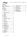
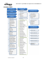
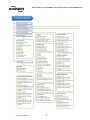
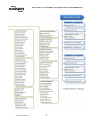
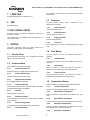
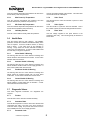
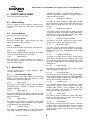
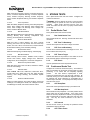
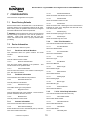
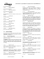
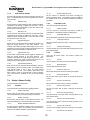
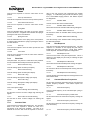
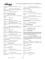
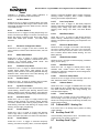
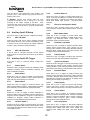
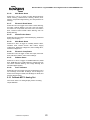
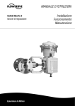
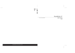
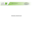
Device Description User Manual Logix® MD+ Positioners with HART® asdf DD User Manual - Logix® 520MD+ Series Digital Positioner FCD-LGENSF0013-01 CONTENTS DD MENU CHART .................................. 3 8 AUXILIARY CARDS ........................20 GENERAL INFORMATION ....................... 6 8.1 8.2 8.3 8.4 8.5 8.6 8.7 8.8 8.9 8.10 AUXILIARY CARD 1 ID ..................................................... 20 AUXILIARY CARD 1 TYPE.................................................. 20 AUXILIARY CARD 1 DI SETUP ........................................... 20 AUXILIARY CARD 1 DO TRIGGER....................................... 20 CALIBRATE MFC 1 ANALOG OUT ...................................... 21 AUXILIARY CARD 2 ID ..................................................... 21 AUXILIARY CARD 2 TYPE.................................................. 21 AUXILIARY CARD 2 DI SETUP ........................................... 22 AUXILIARY CARD 2 DO TRIGGER....................................... 22 CALIBRATE MFC 2 ANALOG OUT ...................................... 23 INTRODUCTION .......................................................................... 6 QUALIFIED PERSONNEL ................................................................ 6 USING THIS DOCUMENT .............................................................. 6 TERMS CONCERNING SAFETY ........................................................ 6 1 LONG TAG ..................................... 7 2 TAG ............................................... 7 3* FULL INITIAL SETUP ....................... 7 3 STATUS ......................................... 7 3.1 3.2 3.3 3.4 3.5 3.6 3.7 PRIORITY ALARM ............................................................. 7 COMMAND DATA ............................................................ 7 PRESSURES ..................................................................... 7 HOUR METERS ................................................................ 7 TEMPERATURE HISTORY .................................................... 7 HEALTH DATA ................................................................. 8 DIAGNOSTIC VALUES ........................................................ 8 4 ALERTS AND ALARMS .................... 9 4.1 4.2 4.3 EVENTS HISTORY.............................................................. 9 CURRENT ALARMS ........................................................... 9 STATUS BYTES ................................................................. 9 5 STROKE TESTS ............................ 11 5.1 5.2 PARTIAL STROKE TEST..................................................... 11 CONTINUOUS STROKE TEST ............................................. 11 6 CALIBRATION .............................. 12 6.1 6.2 6.3 6.4 6.5 6.6 CALIBRATE SENSORS ....................................................... 12 CALIBRATE COMMAND INPUT .......................................... 12 CALIBRATION DATES AND TIMES....................................... 12 CALIBRATE MFC ANALOG OUT 1 ..................................... 12 CALIBRATE MFC ANALOG OUT 2 ..................................... 12 CALIBRATION STATUS ..................................................... 12 7 CONFIGURATION ......................... 13 7.1 7.2 7.3 7.4 7.5 7.6 RESET FACTORY DEFAULTS .............................................. 13 DEVICE INFORMATION .................................................... 13 CONTROL CONFIG .......................................................... 14 ALERTS / ALARMS CONFIG .............................................. 16 USER PREFERENCES ........................................................ 19 BURST MODE ................................................................ 20 © Flowserve Corporation 2 DD User Manual - Logix® 520MD+ Series Digital Positioner FCD-LGENSF0013-01 DD MENU CHART © Flowserve Corporation 3 DD User Manual - Logix® 520MD+ Series Digital Positioner FCD-LGENSF0013-01 © Flowserve Corporation 4 DD User Manual - Logix® 520MD+ Series Digital Positioner FCD-LGENSF0013-01 © Flowserve Corporation 5 DD User Manual - Logix® 520MD+ Series Digital Positioner FCD-LGENSF0013-01 GENERAL INFORMATION Introduction This document provides detailed information about the function of the Logix 520MD+ Device Description (DD). The DD follows the protocol provided by the HART Communication Foundation. For more information about downloading, installing and using HART DDs, visit http://www.hartcomm.org/ Qualified Personnel Qualified personnel are people who, on account of their training, experience, instruction and their knowledge of relevant standards, specifications, accident prevention regulations and operating conditions, have been authorized by those responsible for the safety of the plant to perform the necessary work and who can recognize and avoid possible dangers. In using this software, the position and operation of the related valves can be affected. Product users and maintenance personnel should thoroughly review the effects of any functions before applying those functions. Using This Document Terms Concerning Safety The safety terms DANGER, CAUTION and NOTE are used in these instructions to highlight particular dangers and/or to provide additional information on aspects that may not be readily apparent. To avoid possible injury to personnel or damage to valve parts, DANGER and CAUTION notes must be strictly followed. Modifying this product, substituting non-factory parts or using maintenance procedures other than outlined could drastically affect performance and be hazardous to personnel and equipment, and may void existing warranties. NOTE: indicates and provides additional technical information, which may not be very obvious even to qualified personnel. CAUTION: Indicates that minor personal injury and/or property damage can occur if proper precautions are not taken. DANGER: Indicates that death, severe personal injury and/or substantial property damage can occur if proper precautions are not taken. The features listed below are numbered to correspond to their location in the DD menu tree. Some menu items may not be available depending on positioner upgrade status and the presence of auxiliary cards. © Flowserve Corporation 6 DD User Manual - Logix® 520MD+ Series Digital Positioner FCD-LGENSF0013-01 1 LONG TAG The humidity of the positioner’s main circuit board in relative percent (RH). Set the HART long tag. (For HART 6 only.) 3.3 2 TAG Set the HART tag. View the pressure sensor values. diagnostics are required. 3.3.1 3* FULL INITIAL SETUP Set basic values and perform calibrations required for positioner to control. *This menu item is only available when the positioner in in Factory Reset state. View basic information about the current status of the positioner including basic on-line diagnostics. 3.3.2 Priority Alarm View the highest priority alarm. For a complete list of current alarms, see Alarms and Alerts. 3.2 Command Data View command and position information. 3.2.1 Control Input Source Select either analog or digital command input source. 3.2.2 4-20 Command Input View the analog command input value. 3.2.3 Port A Pressure Port B Pressure View the pressure at port B. 3.3.3 Supply Pressure View the supply pressure. Pressures View a graph of Port A, Port B, and Supply pressures. (EDD only.) 3.4 3.1 Advanced or Pro View the pressure at port A. 3.3.4 3 STATUS Pressures Hour Meters View the number of hours the positioner has been in operation. 3.4.1 Lifetime Hours View the total number of hours the positioner has been in operation. 3.4.2 Reset Hours View the number of hours the positioner has been in operation since the last factory reset was performed. 3.4.3 Power up Hours View the number of hours the positioner has been in operation since the last time it was powered up. Digital Command Input Set the digital command input value. 3.5 3.2.4 View the positioner temperature and humidity information. Control Command View the final command after Characterization, Soft Limits, and Tight Shut-Off effects are applied. 3.2.5 Position View the position of the valve. 3.2.6 Position Deviation View the difference between the Control (Final) Command and the Position. 3.2.7 Current Temperature The temperature of the positioner’s main circuit board. 3.2.8 Current Humidity 3.5.1 Current Temperature View the current temperature inside the positioner. 3.5.2 Max Lifetime Temperature View the maximum temperature the positioner has ever seen. 3.5.3 Min Lifetime Temperature View the minimum temperature the positioner has ever seen. 3.5.4 Max Reset Temperature View the maximum temperature the positioner has seen since the last factory reset was performed. 3.5.5 © Flowserve Corporation Temperature History 7 Min Reset Temperature DD User Manual - Logix® 520MD+ Series Digital Positioner FCD-LGENSF0013-01 View the minimum temperature the positioner has seen since the last factory reset was performed. View the pneumatic leakage of the actuator. This value does not include normal air consumption. 3.5.6 3.7.4 Max Power Up Temperature Valve Travel View the maximum temperature the positioner has seen since the last time the positioner was powered up. View the amount the valve has traveled in percent of total stroke length. 3.5.7 3.7.5 Min Power Up Temperature Valve Cycles View the minimum temperature the positioner has seen since the last time the positioner was powered up. View the number of cycles the valve has travelled. This is the number of times the valve has changed directions twice. 3.5.8 3.7.6 Humidity Percent View the current relative humidity inside the positioner. 3.6 View the voltage supplied to the piezo element in the positioner's pilot relay. This should typically be between 0 and 24 VDC. Health Data View the warning level for each category. The 520MD+ positioner monitors the conditions that affect the ability of the valve to respond. As these conditions worsen, a warning level is shown. A low value such as 0% indicates no warning. A high value such as 90% indicates the ability to control may be impaired soon. A value of 100 indicates that the valve may no longer be responsive. 3.6.1 Valve Health % Warning The warning value from 0 to 100% based on warnings and alarms related to valve health such as friction. A lower value indicates less serious issues. 3.6.2 Actuator Health % Warning The warning value from 0 to 100% based on warnings and alarms related to actuator health such as supply pressure. A lower value indicates less serious issues. 3.6.3 Positioner Health % Warning The warning value from 0 to 100% based on warnings and alarms related to positioner health such as circuit board malfunction. A lower value indicates less serious issues. 3.6.4 Control Health % Warning The warning value from 0 to 100% based on warnings and alarms related to control health such as deviation. A lower value indicates less serious issues. 3.7 Diagnostic Values View basic diagnostic information. Pro diagnostics are required. 3.7.1 Friction View the friction of the valve and actuator assembly. 3.7.2 Actuation Ratio View the effort required to move the valve in the direction that compresses the spring. The ratio is the force required to overcome friction, spring, and process load forces over the force available from the current supply pressure. 3.7.3 Pneumatic Leak © Flowserve Corporation Piezo Volts 8 DD User Manual - Logix® 520MD+ Series Digital Positioner FCD-LGENSF0013-01 Calibration in Progress, Command Input Calibration in Progress, Analog Output Calibration In Progress, and Jog Calibration Set 100% Position. 4 ALERTS AND ALARMS View and manage alerts and alarms. 4.3.1.5 4.1 Events History View the complete list of events (alarms, calibrations etc.). The latest event is shown first. Select OK to view previous events. Calibration Error Status 1 View status of Position Range Too Small, Position Sensor Below ADC Range, Position Sensor Above ADC Range, No Motion Time Out, Settle Time Out, and Inner Loop Offset Time Out. 4.3.1.6 Calibration Error Status 2 View the current status of all alarms. View status of Analog Output Range Too Small, Command Input Range Too Small, Command Input Below ADC Range, Command Input Above ADC Range, Stroke Shift, Stroke Span Increase , and Stroke Span Decrease . 4.2.1 4.3.1.7 4.2 Current Alarms Priority Alarm Electronic Configuration Status View the top priority alarm. Other alarms may be active. This alarm may be the root of the issue. View status of Aux Card 1 Present, Aux Card 2 Present, Pressure Sensor Board Present, and LCD Present. 4.2.2 4.3.1.8 Modes View the modes or behavior configurations of the positioner. 4.2.2.1 Mode Status 1 View the status of Digital Command, Tight Shut Off, Pressure Control, Soft Stop, and Backup Control modes. 4.2.2.2 Mode Status 2 View the status of Continuous Stroke Test, Training In Progress, Training Complete, Event Capture, Local Interface Lock, and Squawk modes. View status of Factory Reset State, Calibration in Progress, Signature or Partial Stroke Test in Progress, Jog Command Mode, Partial Stroke Test Scheduled, and DI Command Override. 4.3.1.9 Status Bytes View a comprehensive list of status indicators. unwanted alerts and alarms. 4.3.1 Mask Unmasked Status Bytes Feedback Loop Status View status of Position Deviation Alarm, Position Sensor Failure Alarm, Valve Opened Too Far Warning, Valve Closed Too Far Warning, Backlash Warning, Backlash Alarm, Partial Stroke Test Failed Warning, and Continuous Stroke Test Failed Warning. 4.3.1.10 4.3 Mode States Status Position Status View status of Position High Limit Alert, Position Low Limit Alert and Feedback Linkage Alarm. 4.3.1.11 Cycles/Travel status View the condition of each status indicator before masking. Masking prevents specific alerts and alarms from being included in the command 48 feedback. View status of Valve Cycles Warning, Valve Travel Warning, Actuator Cycles Warning, Actuator Travel Warning, Bellows Cycles Warning, Bellows Travel Warning, Pilot Relay Cycles Warning, and Pilot Relay Travel Warning. 4.3.1.1 4.3.1.12 Startup Status View status of Power ON, Initializing, Stroke Calibration Required, Pressure Calibration Required, and Friction Calibration Required. 4.3.1.2 Mode Status 1 View status of Digital Command Mode, Tight Shut Off Mode, Pressure Control Locked, Soft Stop High Limit Alert, and Soft Stop Low Limit Alert. 4.3.1.3 Mode Status 2 View status of Continuous Stroke Test Mode, Training Mode In Progress, Training Mode Completed, Event Captured, Local Interface Off, and Squawk Mode. 4.3.1.4 Calibration Status View status of Stroke Calibration in Progress, Setting Inner Loop Offset, Pressure Calibration in Progress, Friction © Flowserve Corporation Actuation Status View status of Supply Pressure High Warning, Supply Pressure Low Warning, Supply Pressure Low Alarm, Actuation Ratio Warning, Spring Unable to Fail Safe Warning, Pneumatic Leak Warning, Air Supply Humid Warning, and Air Supply Icing Warning. 4.3.1.13 Friction Status View status of Friction High Warning, Friction High Alarm, Friction Low Warning, Friction Low Alarm, Valve Can't Open Alarm, and Valve Can't Shut Alarm. 4.3.1.14 Control Status View status of Command Frequency Warning, Command Frequency Alarm, Command Amplitude Warning, Command Amplitude Alarm, Position Frequency Warning, Position Frequency Alarm, Position Amplitude Warning, and Position Amplitude Alarm. 9 DD User Manual - Logix® 520MD+ Series Digital Positioner FCD-LGENSF0013-01 4.3.1.15 Inner Loop Status View status of Pilot Relay Response Warning, Pilot Relay Response Alarm, Piezo Voltage High Warning, Piezo Voltage High Alarm, Piezo Voltage Low Warning, Piezo Voltage Low Alarm, and Driver Module Alarm. 4.3.1.16 Main Board Status View status of Main Board Electronic Failure Warning, Software Error Warning, Memory Error Warning, Temperature High Warning, and Temperature Low Warning. 4.3.1.17 Electronic Board Status View status of Aux Card 1 Failure Warning, Aux Card 2 Failure Warning, Aux Card 1 No Loop Power, Aux Card 2 No Loop Power, Aux Card 1 Error, Aux Card 2 Error, Pressure Sensor Board Failure Warning, and Low Battery Warning. 4.3.1.18 Stroke/Friction status Mask Continuous Stroke Test Mode, Training Mode In Progress, Training Mode Completed, Event Captured, Local Interface Off, and Squawk Mode. 4.3.2.4 Calibration Status Mask Stroke Calibration in Progress, Setting Inner Loop Offset, Pressure Calibration in Progress, Friction Calibration in Progress, Command Input Calibration in Progress, Analog Output Calibration In Progress, and Jog Calibration Set 100% Position. 4.3.2.5 Calibration Error Status 1 Mask Position Range Too Small, Position Sensor Below ADC Range, Position Sensor Above ADC Range, No Motion Time Out, Settle Time Out, and Inner Loop Offset Time Out. 4.3.2.6 Calibration Error Status 2 View status of Reversed Spring, Insufficient Spring, and No Spring. Mask Analog Output Range Too Small, Command Input Range Too Small, Command Input Below ADC Range, Command Input Above ADC Range, Stroke Shift, Stroke Span Increase , and Stroke Span Decrease. 4.3.1.19 4.3.2.7 Main Board Status Electronic Configuration Status View status of Humidity Sensor Failure, Oscillator Fault, Position Sensor ADC Failure, Supply Voltage Error, Reference Voltage Error, Shunt Voltage Error, and Piezo Voltage Error. Mask Aux Card 1 Present, Aux Card 2 Present, Pressure Sensor Board Present, and LCD Present. 4.3.1.20 Mask Factory Reset State, Calibration in Progress, Signature or Partial Stroke Test in Progress, Jog Command Mode, Partial Stroke Test Scheduled, and DI Command Override. Electrical Components Status View status of Pilot Can't Open, Pilot Can't Shut, Hall Sensor Failure, and ILO Out Of Range. 4.3.1.21 Software Status 4.3.2.8 4.3.2.9 Mode States Status Feedback Loop Status View status of NVMEM CRC Error, RAM Error, RAM CRC Error, FLASH CRC Error, Watch Dog Time Out, Stack Overflow Warning, CPU Usage Warning, and Firmware Update Applied. Mask Position Deviation Alarm, Position Sensor Failure Alarm, Valve Opened Too Far Warning, Valve Closed Too Far Warning, Backlash Warning, Backlash Alarm, Partial Stroke Test Failed Warning, and Continuous Stroke Test Failed Warning. 4.3.1.22 4.3.2.10 Pressure Calibration Status Position Status View status of Port S Out Of Range, Port A Out Of Range, Port B Out Of Range, Port S Range too Small, Port A Range too Small, Port B Range too Small, and Pressure Sensor Failure. Mask Position High Limit Alert, Position Low Limit Alert and Feedback Linkage Alarm. 4.3.2 Mask Valve Cycles Warning, Valve Travel Warning, Actuator Cycles Warning, Actuator Travel Warning, Bellows Cycles Warning, Bellows Travel Warning, Pilot Relay Cycles Warning, and Pilot Relay Travel Warning. Status Byte Masks Mask status indicators from appearing in command 48. This applies only to warnings, alarms and alerts that affect the health of the system. 4.3.2.1 Startup Status Mask Power ON, Initializing, Stroke Calibration Required, Pressure Calibration Required, and Friction Calibration Required. 4.3.2.2 Mode Status 1 Mask Digital Command Mode, Tight Shut Off Mode, Pressure Control Locked, Soft Stop High Limit Alert, and Soft Stop Low Limit Alert. 4.3.2.3 Mode Status 2 4.3.2.11 4.3.2.12 Actuation Status Mask Supply Pressure High Warning, Supply Pressure Low Warning, Supply Pressure Low Alarm, Actuation Ratio Warning, Spring Unable to Fail Safe Warning, Pneumatic Leak Warning, Air Supply Humid Warning, and Air Supply Icing Warning. 4.3.2.13 Friction Status Mask Friction High Warning, Friction High Alarm, Friction Low Warning, Friction Low Alarm, Valve Can't Open Alarm, and Valve Can't Shut Alarm. 4.3.2.14 © Flowserve Corporation Cycles/Travel status 10 Control Status DD User Manual - Logix® 520MD+ Series Digital Positioner FCD-LGENSF0013-01 Mask Command Frequency Warning, Command Frequency Alarm, Command Amplitude Warning, Command Amplitude Alarm, Position Frequency Warning, Position Frequency Alarm, Position Amplitude Warning, and Position Amplitude Alarm. 5 STROKE TESTS 4.3.2.15 and the inability to operate the valve until the operation is complete. Notify proper personnel that the valve may stroke, and make sure the valve is properly isolated before proceeding. Inner Loop Status Mask Pilot Relay Response Warning, Pilot Relay Response Alarm, Piezo Voltage High Warning, Piezo Voltage High Alarm, Piezo Voltage Low Warning, Piezo Voltage Low Alarm, and Driver Module Alarm. 4.3.2.16 Main Board Status Mask Main Board Electronic Failure Warning, Software Error Warning, Memory Error Warning, Temperature High Warning, and Temperature Low Warning. 4.3.2.17 Electronic Board Status Run a partial stroke tests and view results. Configure the continuous stroke test. DANGER: Using this feature will result in valve movement 5.1 Partial Stroke Test Run a partial stroke tests and view results. 5.1.1 Run Partial Stroke Test Start a partial stroke test. Warning: The PST will cause valve movement. Mask Aux Card 1 Failure Warning, Aux Card 2 Failure Warning, Aux Card 1 No Loop Power, Aux Card 2 No Loop Power, Aux Card 1 Error, Aux Card 2 Error, Pressure Sensor Board Failure Warning, and Low Battery Warning. 5.1.2 4.3.2.18 Mask Reversed Spring, Insufficient Spring, and No Spring. View the force recorded when the valve began to move. This force is valid for slow ramps only. 4.3.2.19 5.1.4 Stroke/Friction status Main Board Status Mask Humidity Sensor Failure, Oscillator Fault, Position Sensor ADC Failure, Supply Voltage Error, Reference Voltage Error, Shunt Voltage Error, and Piezo Voltage Error. 4.3.2.20 Electrical Components Status Mask Pilot Can't Open, Pilot Can't Shut, Hall Sensor Failure, and ILO Out Of Range. 4.3.2.21 Software Status Mask NVMEM CRC Error, RAM Error, RAM CRC Error, FLASH CRC Error, Watch Dog Time Out, Stack Overflow Warning, CPU Usage Warning, and Firmware Update Applied. 4.3.2.22 Pressure Calibration Status Mask Port S Out Of Range, Port A Out Of Range, Port B Out Of Range, Port S Range too Small, Port A Range too Small, Port B Range too Small, and Pressure Sensor Failure. PST Time To Breakaway View the time required for the valve to begin movement. 5.1.3 PST Force at Breakaway PST Time to Target View the time taken for the position to come within 2% of the final command after the initial change in command. 5.1.5 PST Result View the pass/fail result of the last partial stroke test. 5.2 Continuous Stroke Test Configure the continuous stroke test (CST). This feature is NOT recommended for processes requiring highly accurate positioning, or for valves that are frequently adjusting position. The CST function superimposes a small, continuous bi-directional ramp over the input command. By constantly moving the valve, additional diagnostic data can be gathered that would otherwise be unavailable with a constant input command. The superimposed ramp reverses when the valve moves. 5.2.1 CST Ramp Rate Set the rate of the superimposed ramp in percent/second. 5.2.2 CST Max Amplitude Set the maximum ramp amplitude. The valve position will not always follow the full ramp amplitude. If the valve moves before the full ramp amplitude is reached, the superimposed ramp command will be reversed, edging the valve the other way. This way the actual movement of the valve is minimized. 5.2.3 CST Interval Set the amount of time (in seconds) the positioner should wait between ramping attempts. 5.2.4 © Flowserve Corporation 11 CST Failure Count DD User Manual - Logix® 520MD+ Series Digital Positioner FCD-LGENSF0013-01 View the number of times the valve failed to move at the end of a ramp. 6 CALIBRATION 5.2.5 Calibrate all aspects of the positioner. CST On/Off Turn CST on or off. Warning: The CST will cause small periodic valve movements. 6.1 Calibrate Sensors Calibrate the stroke, pressure sensors, friction feature, or all of them in one operation using the "Triple" calibration. 6.2 Calibrate Command Input Calibrate the analog command input. Typically this will be 4 to 20 mA. However, a split range can be set also. DANGER: Using this feature will result in valve movement and the inability to operate the valve until the operation is complete. Notify proper personnel that the valve may stroke, and make sure the valve is properly isolated before proceeding. 6.3 Calibration Dates and Times View a history of previous calibration dates and times. 6.4 Calibrate MFC Analog Out 1 Calibrate the analog output. A multi-function card (MFC) must be installed in slot 1 and configured for the AO function. 6.5 Calibrate MFC Analog Out 2 Calibrate the analog output. A multi-function card (MFC) must be installed in slot 2 and configured for the AO function. 6.6 Calibration Status View details about the calibration flags. 6.6.1 StartUp Status View the state of the positioner including Power ON, Initializing, Stroke Calibration Required, Pressure Calibration Required, and Friction Calibration Required. 6.6.2 Calibration Status View the state of the positioner including Stroke Calibration in Progress, Setting Inner Loop Offset, Pressure Calibration in Progress, Friction Calibration in Progress, Command Input Calibration in Progress, Analog Output Calibration In Progress, and Jog Calibration Set 100% Position. © Flowserve Corporation 12 DD User Manual - Logix® 520MD+ Series Digital Positioner FCD-LGENSF0013-01 7.2.3.2 7 CONFIGURATION Actuator Manufacturer Select the actuator manufacturer from a list. View and set the configuration of the system. 7.2.3.3 Actuator Model Select the actuator model from a list. 7.1 Reset Factory Defaults 7.2.3.4 Reset all values back to the default state. This will affect the positioner behavior and configuration settings will be reset. After a factory reset, the positioner will need to be configured and stroke calibration will need to be performed. DANGER: Using this feature will result in valve movement and the inability to operate the valve until the positioner is calibrated. Notify proper personnel that the valve may stroke, and make sure the valve is properly isolated before proceeding. Select the actuator size. Selecting the area of the actuator is important for some of the diagnostics that deal with force, such as the friction values. 7.2.3.5 7.2.3.6 Select the actuator style from a list. 7.2.4.1 Valve Trim Information Trim Number/Size Set the Trim Number/Size. Revisions and Serial Numbers View information about the system revisions and serial numbers. 7.2.1.1 Actuator Style View and set information about the valve trim. Device Information View the information about the system . 7.2.1 Actuator Spring Select the actuator spring type from a list. 7.2.4 7.2 Actuator Size 7.2.4.2 Set the Trim Characteristic. 7.2.4.3 Software Release Trim Characteristic Trim Type View the software version number. Set the Trim Type. 7.2.1.2 7.2.4.4 Electronic Serial Number View the serial number assigned to the positioner. number is listed on the positioner label. 7.2.1.3 This Valve Serial Number View the valve serial number. This number is entered by the user. See Valve Information. 7.2.2 Positioner Information View information about HART and the positioner. 7.2.2.1 HART Manufacturer ID View the positioner manufacturer. 7.2.2.2 HART Device Type View HART device type of the positioner. 7.2.2.3 Diagnostics Level View the diagnostic level of the positioner. Three levels are possible - Standard, Advanced, and Pro. 7.2.2.4 Model Number Trim Material Set the Trim Material. 7.2.4.5 Stroke Length Set the Stroke Length. 7.2.4.6 Stem Diameter Set the Stem Diameter. 7.2.4.7 Packing Style Set the Packing Style. 7.2.4.8 Bonnet Type Set the Bonnet Type. 7.2.4.9 Pressure Balance Set the Pressure Balance. 7.2.5 7.2.5.0 - Valve Body Information View and set information about the valve body. 7.2.5.1 Valve Serial Number View the positioner model number. Set the Valve Serial Number. 7.2.3 7.2.5.2 Actuator Information Valve Manufacturer View and set information about the actuators. Set the Valve Manufacturer. 7.2.3.1 7.2.5.3 Select Actuator Settings Select actuators from a list to automatically look up and store some of the actuator information. © Flowserve Corporation Valve Model Set the Valve Model. 7.2.5.4 13 Valve Body Size DD User Manual - Logix® 520MD+ Series Digital Positioner FCD-LGENSF0013-01 Set the Valve Body Size. 7.3.1.4 7.2.5.5 Override the DIP switch on the positioner to change the Characterization. Select Linear or Other. If Other is selected, choose a characterization curve using "Other Characterization" below. Valve Body Material Set the Valve Body Material. 7.2.5.6 Valve End Connections Dip Sw Characterization Set the Valve End Connections. 7.3.1.5 7.2.5.7 If the Characterization Dip Switch is set to "Other", select the desired characterization curve. The Custom curve has a default of equal percent for linear valves. Fail Direction Set the direction the valve is tubed to fail upon loss of pressure. 7.2.5.8 Flow Direction Set if flow direction. 7.2.5.9 Valve Type Set rotary or linear. 7.2.5.10 Valve Pressure Class Set the Valve Pressure Class. 7.2.5.11 Valve Leak Class Set the Valve Leak Class. 7.2.5.12 Valve Inlet Pressure 7.3.1.6 Other Characterization Dip Sw Auto Tune Override the DIP switch on the positioner to change the Auto Tune setting. Select On or Off. Selecting On enables an auto tune feature that will automatically determine the positioner gain settings during a Quick-Cal. Selecting Off tells the positioner to use the factory preset tuning levels determined by the gain selector switch. 7.3.1.7 Dip Sw Quick Cal Override the DIP switch on the positioner to change the Quick Cal mode. Select Auto or Jog. Select Auto under most circumstances. Select Jog if there is no hard stop on the valve at the 100% open position. When performing a Quick-Cal, the 100% position can be manually set. Set the Valve Inlet Pressure. 7.3.1.8 7.2.5.13 Override the DIP switch on the positioner to change the Valve Stability. Select Low Friction or High Friction. Placing the switch to Lo Friction optimizes the response for low friction, high performance control valves. Placing the switch to the right optimizes the response for valves and actuators with high friction levels. Valve Outlet Pressure Set the Valve Outlet Pressure. 7.3 Control Config Set parameters the affect the control of the valve. Warning: Adjusting the control configuration will affect the way the valve position is controlled. 7.3.1 Device Configuration Override DIP switch settings, reverse the LCD, set fail position, view relay type DANGER: Changing the DIP Switch settings can affect how the valve controls and may cause sudden valve movement. Notify proper personnel that the valve may stroke, and make sure the valve is properly isolated before proceeding. 7.3.1.9 Dip Sw Air Action Override the DIP switch on the positioner to change the Air Action. Select Air to Open or Air to Close. 7.3.1.2 Dip Sw Actuator Override the DIP switch on the positioner to change the Actuator action. Select Double or Single. This is only applicable for positioners with double acting relay modules. 7.3.1.3 Dip Sw Sig Closed Override the DIP switch on the positioner to change the Signal at Closed. Select 4 mA or 20 mA. © Flowserve Corporation Dip Sw Spare The Spare DIP typically has no function and is reserved for special features. 7.3.1.10 Fail Direction Record the fail direction. Select Closed or Open. This entry does not affect the function of the positioner or the fail position of the valve. It is only a label. 7.3.1.11 Flow Direction Record the flow direction. Select Over, Under or Other. This should represent the configuration of the valve. 7.3.1.12 7.3.1.1 Dip Sw Stability Valve Type Record the valve type. Select Linear or Rotary. This entry does not affect the function of the positioner. It is only a label. 7.3.1.13 LCD Orientation Select the LCD orientation. Select Normal or Reversed. Reversed will flip the LDC display upside down. 7.3.1.14 Pilot Relay Type View the pilot relay type. Spool relays have higher capacity. Poppet relays have lower air consumption. 7.3.1.15 14 Pressure Board Status DD User Manual - Logix® 520MD+ Series Digital Positioner FCD-LGENSF0013-01 View if the pressure sensor board is installed. 7.3.2.11 7.3.1.16 View if the LCD is installed. Adjust the integral gain in the close direction. Use caution when adjusting gain settings. Small changes can cause the valve position to go unstable. 7.3.2 7.3.2.12 LCD Avail Status Positioner Tuning View and adjust tuning parameters DANGER: Changing the tuning parameters can affect how the valve controls and may cause sudden valve movement. Notify proper personnel that the valve may stroke, and make sure the valve is properly isolated before proceeding. 7.3.2.1 Rotary Switch Settings View the rotary switch setting. This is a live manual tune selector. Use this as a first option when adjusting the tuning. 7.3.2.2 P-Gain Mult Open Adjust the proportional gain multiplier in the open direction. Use caution when adjusting gain settings. Small changes can cause the valve position to go unstable. 7.3.2.3 P-Gain Mult Close Adjust the proportional gain multiplier in the close direction. Use caution when adjusting gain settings. Small changes can cause the valve position to go unstable. 7.3.2.4 P-Gain Max Open Adjust the maximum proportional gain setting in the open direction. Use caution when adjusting gain settings. Small changes can cause the valve position to go unstable. 7.3.2.5 P-Gain Max Close Adjust the maximum proportional gain setting in the close direction. Use caution when adjusting gain settings. Small changes can cause the valve position to go unstable. 7.3.2.6 D-Term Depth Open Adjust the derivative gain depth in the open direction. Use caution when adjusting gain settings. Small changes can cause the valve position to go unstable. 7.3.2.7 D-Term Depth Close Adjust the derivative gain depth in the close direction. Use caution when adjusting gain settings. Small changes can cause the valve position to go unstable. 7.3.2.8 D-Gain Basic Open Adjust the basic derivative gain in the open direction. Use caution when adjusting gain settings. Small changes can cause the valve position to go unstable. 7.3.2.9 D-Gain Basic Close Adjust the basic derivative gain in the close direction. Use caution when adjusting gain settings. Small changes can cause the valve position to go unstable. 7.3.2.10 I-Gain Open Adjust the integral gain in the open direction. Use caution when adjusting gain settings. Small changes can cause the valve position to go unstable. © Flowserve Corporation I-Gain Close Stroke Time Open Adjust the stroke time in the open direction. This time is determined at calibration. A smaller stroke time will increase the responsiveness in the open direction. 7.3.2.13 Stroke Time Close Adjust the stroke time in the close direction. This time is determined at calibration. A smaller stroke time will increase the responsiveness in the close direction. 7.3.2.14 Min Open Time Set the minimum open time. This is a speed limit for any movement of the valve in the open direction. The maximum rate will be 100% / Min Open Time. 7.3.2.15 Min Close Time Set the minimum close time. This is a speed limit for any movement of the valve in the close direction. The maximum rate will be 100% / Min Close Time. 7.3.2.16 Inner Loop Offset Set the Inner Loop Offset. This is automatically determined at calibration. Do not adjust this unless the positioner is not responding and the current value is not between 30% and 70%. 7.3.3 Pressure Control View and set the pressure control lock parameters. When the Valve Stability DIP switch is set to High Friction and the deviation is less than the Window value, the position will be locked based on pressure control rather than position feedback. When the Valve Stability DIP switch is set to Low Friction, the pressure window is automatically optimized to be as small as possible. 7.3.3.1 Pressure Lock View the status of the pressure lock. 7.3.3.2 Window Multiplier Set the window multiplier value for automatic optimization of the pressure control window when the Valve Stability DIP switch is set to Low Friction. Typically this value does not need adjustment. 7.3.3.3 Window Gain Set the window gain value for automatic optimization of the pressure control window when the Valve Stability DIP switch is set to Low Friction. Typically this value does not need adjustment. 7.3.3.4 Window Set the size pressure control window when the Valve Stability DIP switch is set to Hi Friction. A larger window will stop valve oscillations caused by very high friction. A smaller window will allow more accurate valve positioning. 15 DD User Manual - Logix® 520MD+ Series Digital Positioner FCD-LGENSF0013-01 7.3.4 Soft Limits & Shutoff Set Soft Limits that stop the valve from traveling beyond a set point. Set Shutoff limits that cause full pressure to close or open the valve. 7.3.4.1 Soft Stop High Set the maximum valve position the final command will allow, regardless of the analog or digital input command. This is similar to placing a physical block on the valve stem to limit the amount the valve can open. 7.3.4.2 Soft Stop Low Set the minimum valve position the final command will allow, regardless of the analog or digital input command. This is similar to placing a physical block on the valve stem to limit the amount the valve can close. 7.3.4.3 Tight Shutoff Upper Set the upper command limit that will trigger the positioner to apply full supply pressure in the open direction. For example, after setting the Tight Shutoff Upper to 95%, if the positioner receives any input command greater than 95%, full supply pressure will be applied to open the valve. 7.3.4.4 Tight Shutoff Lower Set the lower command limit that will trigger the positioner to apply full supply pressure in the close direction. For example, after setting the Tight Shutoff Upper to 5%, if the positioner receives any input command less than 5%, full supply pressure will be applied to close the valve. 7.3.4.5 Tight Shutoff Hysteresis Enter the amount the command must backtrack in order for the positioner to return to regular control. For example, it the Tight Shutoff Upper is set to 90%, and Tight Shutoff Hysteresis is set at 2%. The command must return from 90% to 88% in order for the positioner to control normally. This is to prevent an oscillation in and out of Tight Shutoff mode. 7.4.1.4 Position Deviation Time Set the amount of allowable time before sounding the Position Deviation alarm. The deviation must be outside of the deviation limit set in the Position Deviation Dead Band parameter. 7.4.2 Pneumatic Leak View and set pneumatic leak limits. 7.4.2.1 Leak Pneumatic View the amount of pneumatic leak beyond normal air consumption. This feature requires Pro diagnostics. 7.4.2.2 Leak High Start Limit Set the pneumatic leak limit at which a warning will appear. 7.4.2.3 Leak High End Limit Set the pneumatic leak limit at which a warning will show full severity. 7.4.2.4 Leak Percent Warning View the severity of the pneumatic leak warning based on the Start and End limits. 7.4.3 Friction View and set friction limits. This feature requires Pro diagnostics. 7.4.3.1 Friction View the friction of the valve and actuator assembly. 7.4.3.2 Nominal Friction View the last saved friction value. 7.4.3.3 Friction Hi Start Limit Set the high friction limit at which a warning will appear. 7.4.3.4 Friction Hi End Limit Set the high friction limit at which a warning will show full severity. 7.4 Alerts / Alarms Config 7.4.3.5 Friction Low Start Limit View and set alarm and alert limits. Set the low friction limit at which a warning will appear. 7.4.1 7.4.3.6 Position View and set alarm and alert limits regarding position. 7.4.1.1 Position High Alert Set the upper limit at which an alert will be sounded. The valve will be allowed to continue travel beyond this point. 7.4.1.2 Position Low Alert Set the lower limit at which an alert will be sounded. The valve will be allowed to continue travel beyond this point. 7.4.1.3 Position Deviation Dead band Set the amount of allowable deviation before sounding the Position Deviation alarm. The deviation must remain for the time set in the Position Deviation Time parameter. © Flowserve Corporation Friction Low End Limit Set the low friction limit at which a warning will show full severity. 7.4.3.7 Friction Hi Percent Warning View the severity of the high friction warning based on the Start and End limits. 7.4.3.8 Friction Low Percent Warning View the severity of the low friction warning based on the Start and End limits. 7.4.3.9 Force Up at 15 Percent View the force required to move the valve up at 15% position. 7.4.3.10 16 Force Down at 15 Percent DD User Manual - Logix® 520MD+ Series Digital Positioner FCD-LGENSF0013-01 View the force required to move the valve down at 15% position. 7.4.3.11 Force Up at 85 Percent valve to the end of travel, fully compressing the actuator spring(s). It is affected by the process load, friction, spring force, and available supply pressure. This feature requires Pro diagnostics. View the force required to move the valve up at 85% position. 7.4.5.1 7.4.3.12 View the current value of the Actuation Ratio. Force Down at 85 Percent View the force required to move the valve down at 85% position. 7.4.3.13 Spring Rate View the calculated spring rate which is the force change over the full stroke. A negative value indicates the spring is pushing the valve in the close direction. 7.4.3.14 Spring Pre Load View the estimated force of the spring at the close position. A negative value indicates the spring is pushing the valve in the close direction. 7.4.3.15 Force Up View the force required to move the valve up under the most recent conditions. 7.4.3.16 Force Down View the force required to move the valve down under the most recent conditions. 7.4.4 Piezo Data View piezo data. The piezo is a small valve in the positioner that is controlled electronically and drives the pilot relay. 7.4.4.1 Piezo Command 1 Avg View the average piezo command (1st aspect). 7.4.4.2 Piezo Command 2 Avg 7.4.5.2 Actuation Ratio Actuation Ratio Hi Start Limit Set the limit at which an Actuation Ratio warning will appear. 7.4.5.3 Actuation Ratio Hi End Limit Set the limit at which an Actuation Ratio warning will show full severity. 7.4.5.4 Actuation Ration Percent Warning View the severity of the Actuation Ratio warning based on the Start and End limits. 7.4.6 Pilot Response View and set the Pilot Response warning limits. The pilot response is a measure of how rapidly the pilot relay is following the pilot relay command. Longer times indicate slower response. This feature requires Pro diagnostics. 7.4.6.1 Pilot Response Time View the current value of the pilot response time. This is a measure of how rapidly the pilot relay is following the pilot relay command. 7.4.6.2 Pilot Response Hi Start Limit Set the limit at which the Pilot Response warning will appear. 7.4.6.3 Pilot Response Hi End Limit Set the limit at which the Pilot Response warning will show full severity. View the average piezo command (2nd aspect). 7.4.6.4 7.4.4.3 View the average actual piezo voltage (1st aspect). View the severity of the Pilot Response warning based on the Start and End limits. 7.4.4.4 7.4.7 Piezo Volts 1 Avg Piezo Volts 2 Avg View the average actual piezo voltage (2nd aspect). 7.4.4.5 Piezo Volts Pilot Response Percent Warning Command/Position Frequencies Set and view parameters associated with the command and position frequency amplitude. This feature requires Pro diagnostics. View current piezo voltage. 7.4.7.1 7.4.4.6 View the typical frequency of the command input cycling In cycles/hour. Piezo Volts High Percent Warning Set the limit at which an Piezo Voltage High warning will appear. 7.4.4.7 Piezo Volts Low Percent Warning Set the limit at which a Piezo Voltage Low warning will appear. 7.4.5 Actuation Ratio View and set the Actuation Ratio alarm limits. The Actuation Ratio is the force required to actuate the valve as a percentage of the total force available. The value is an estimate of the force that would be required to move the © Flowserve Corporation 7.4.7.2 Command Frequency Command Frequency Hi Start Limit Set the limit at which the Command Frequency warning will appear. 7.4.7.3 Command Frequency Hi End Limit Set the limit at which the Command Frequency warning will show full severity. 7.4.7.4 17 Command Frequency Hi Percent Warning DD User Manual - Logix® 520MD+ Series Digital Positioner FCD-LGENSF0013-01 View the severity of the Command Frequency warning based on the Start and End limits. Set the limit at which the Valve Travel warning will show full severity. 7.4.7.5 7.4.8.4 Command Amplitude View the typical amplitude of the command input. 7.4.7.6 Command Amplitude Hi Start Limit Set the limit at which the Command Amplitude warning will appear. 7.4.7.7 Command Amplitude Hi End Limit Set the limit at which the Command Amplitude warning will show full severity. 7.4.7.8 Command Amplitude Hi Percent Warning View the severity of the Command Amplitude warning based on the Start and End limits. 7.4.7.9 Position Frequency View the typical frequency of the position cycling in cycles/hour. 7.4.7.10 Position Frequency Hi Start limit Set the limit at which the Position Frequency warning will appear. 7.4.7.11 Position Frequency Hi End Limit Set the limit at which the Position Frequency warning will show full severity. 7.4.7.12 Position Frequency Hi Percent Warning Valve Travel Hi Percent Warning View the severity of the Valve Travel warning based on the Start and End limits. 7.4.8.5 Valve Travel Dead Band Set the amount the valve must move in order to begin adding to the travel total. 7.4.8.6 Valve Cycles View the total valve cycles. 7.4.8.7 Valve Cycles Hi Start Limit Set the limit at which the Valve Cycles warning will appear. 7.4.8.8 Valve Cycles Hi End Limit Set the limit at which the Valve Cycles warning will show full severity. 7.4.8.9 Valve Cycles Hi Percent Warning View the severity of the Valve Cycles warning based on the Start and End limits. 7.4.8.10 Valve Cycle Dead Band Set the amount the valve must move in order to begin adding to the travel and cycle totals. 7.4.8.11 Stroke Length Enter the stroke length of the valve. View the severity of the Position Frequency warning based on the Start and End limits. 7.4.8.12 7.4.7.13 Reset the valve travel or cycle counter. Position Amplitude Valve Travel/Cycles Reset View the typical amplitude of the valve position. 7.4.9 7.4.7.14 View and adjust the limits for the actuator cycling and travel warnings. Position Amplitude Hi Start limit Actuator Travel/Cycles Set the limit at which the Position Amplitude warning will appear. 7.4.9.1 7.4.7.15 View the total actuator travel. Position Amplitude Hi End Limit Set the limit at which the Position Amplitude warning will show full severity. 7.4.9.2 7.4.7.16 7.4.9.3 Position Amplitude Hi Percent Warning Actuator Travel Actuator Travel Hi Start Limit Set the limit at which the Actuator Travel warning will appear. Actuator Travel Hi End Limit View the severity of the Position Amplitude warning based on the Start and End limits. Set the limit at which the Actuator Travel warning will show full severity. 7.4.8 7.4.9.4 Valve travel/Cycles Actuator Travel Hi Percent Warning View and adjust the limits for the valve cycling and travel warnings. View the severity of the Actuator Travel warning based on the Start and End limits. 7.4.8.1 7.4.9.5 Valve Travel Actuator Cycles View the total valve travel. View the total actuator cycles. 7.4.8.2 7.4.9.6 Valve Travel Hi Start Limit Set the limit at which the Valve Travel warning will appear. 7.4.8.3 Valve Travel Hi End Limit Set the limit at which the Actuator Cycles warning will appear. 7.4.9.7 © Flowserve Corporation Actuator Cycles Hi Start Limit 18 Actuator Cycles Hi End Limit DD User Manual - Logix® 520MD+ Series Digital Positioner FCD-LGENSF0013-01 Set the limit at which the Actuator Cycles warning will show full severity. 7.4.9.8 Actuator Cycles Hi Percent Warning View the severity of the Actuator Cycles warning based on the Start and End limits. 7.4.9.9 - Actuator Travel/Cycles Reset Reset the actuator travel or cycle counter. 7.4.10 Bellows Travel/Cycles View and adjust the limits for the bellows cycling and travel warnings. 7.4.10.1 Bellows Travel 7.4.11.4 Pilot Travel Hi Percent Warning View the severity of the Pilot Relay Travel warning based on the Start and End limits. 7.4.11.5 Pilot Cycles View the total pilot relay cycles. 7.4.11.6 Pilot Cycles Hi Start Limit Set the limit at which the Pilot Relay Cycles warning will appear. 7.4.11.7 Pilot Cycles Hi End Limit Set the limit at which the Pilot Relay Cycles warning will show full severity. View the total bellows travel. 7.4.11.8 7.4.10.2 View the severity of the Pilot Relay Cycles warning based on the Start and End limits. Bellows Travel Hi Start Limit Set the limit at which the Bellows Travel warning will appear. 7.4.10.3 Bellows Travel Hi End Limit Set the limit at which the Bellows Travel warning will show full severity. 7.4.10.4 Bellows Travel Hi Percent Warning View the severity of the Bellows Travel warning based on the Start and End limits. 7.4.10.5 Bellows Cycles View the total bellows cycles. 7.4.10.6 Bellows Cycles Hi Start Limit Set the limit at which the Bellows Cycles warning will appear. 7.4.10.7 Bellows Cycles Hi End Limit Set the limit at which the Bellows Cycles warning will show full severity. Pilot Cycles Hi Percent Warning 7.4.11.9 Pilot Travel/Cycles Reset Reset the pilot relay travel or cycle counter. 7.5 User Preferences View and set user preferences such as date, interface lock, and units. 7.5.1 View/Set Date and Time View and set the positioner date and time. 7.5.2 Local Interface Lock the local interface of the positioner and set a pin code. Locking the local interface prevents unauthorized changes from taking place at the positioner's button panel that affect the control or configuration of the positioner. 7.5.2.1 Local Interface Enable/Disable View the severity of the Bellows Cycles warning based on the Start and End limits. Lock the local interface so that no adjustments can be made to the control or configuration of the positioner using the buttons on the positioner without a pin code. The gain switch will still be responsive. 7.4.10.9 7.5.2.2 7.4.10.8 Bellows Cycles Hi Percent Warning Bellows Travel/Cycles Reset Reset the bellows travel or cycle counter. 7.4.11 Pilot travel/Cycles View and adjust the limits for the pilot relay cycling and travel warnings. 7.4.11.1 Pilot Travel View the total pilot relay travel. 7.4.11.2 Pilot Travel Hi Start Limit Pin Code Set a pin code to allow access to modify positioner control and configuration parameters at the positioner's local interface. 7.5.3 Select Units Set desired units. 7.5.3.1 Area Units Set area units (in2, cm2) 7.5.3.2 Travel Units Set the limit at which the Pilot Relay Travel warning will appear. Set travel units (%) 7.4.11.3 7.5.3.3 Pilot Travel Hi End Limit Set the limit at which the Pilot Relay Travel warning will show full severity. © Flowserve Corporation Pressure Units Set pressure units (psi, bar, kg/cm2, kPa) 7.5.3.4 19 Force Units DD User Manual - Logix® 520MD+ Series Digital Positioner FCD-LGENSF0013-01 Set force units (lbf, kg, N) 7.5.3.5 Temperature Units Set temperature units (degrees F, degrees C) 7.5.3.6 Air Flow Units 8 AUXILIARY CARDS Manage auxiliary card configuration and view status. These menus change based on the presence of and configuration of the auxiliary cards. Set the air flow units (scfm, slpm, slph, Nm3/hr) 8.1 7.6 View the auxiliary card present in slot 1. This feature is only present if an auxiliary card is in slot 1. Burst Mode Change burst mode settings and activate burst mode. 7.6.1 Burst Command Setup Set burst mode to use command 1, 2, 3, 9, 33, or 48. 7.6.2 Burst State Setup Select out of the following burst mode variables. 7.6.3 Command (mA) Command % (Analog) Command % (Digital) Command % Command % Target Position % Deviation % Pilot Command % Pilot Position % Temperature User Actuation Ratio Pilot Response Time (T86) Pneumatic Leak Pressure Supply Pressure Deviation Pressure Port A Pressure Port B Friction Burst Mode Configuration Turn Burst mode on or off. 8.2 Auxiliary Card 1 ID Auxiliary Card 1 Type View and set the type configuration of the auxiliary card present in slot 1. This feature is only present if an auxiliary card is in slot 1. DANGER: Discrete input settings affect the valve movement by initiating a PST or moving to a set point according to the voltage supplied to the MFC. Verify connections and notify proper personnel that the valve may stroke, and make sure the valve is properly isolated before proceeding. 8.3 Auxiliary Card 1 DI Setup If the card in slot 1 is a Discrete Input, configure the settings. 8.3.1 MFC 1 DI State Select the action when the DI state is triggered. Discrete input settings affect the valve movement by initiating a PST or moving to a set point according to the voltage supplied to the MFC. Verify connections before proceeding. 8.3.2 MFC 1 DI Command If the DI action is Command Override, set the desired position where the valve should move when the DI state is triggered. 8.4 Auxiliary Card 1 DO Trigger If the card in slot 1 is a Discrete Output, configure the settings. 8.4.1 Startup Status Select DO in slot 1 to trigger on Power ON, Initializing, Stroke Calibration Required, Pressure Calibration Required, and Friction Calibration Required. 8.4.2 Mode Status 1 Select DO in slot 1 to trigger on Digital Command Mode, Tight Shut Off Mode, Pressure Control Locked, Soft Stop High Limit Alert, and Soft Stop Low Limit Alert. 8.4.3 Mode Status 2 Select DO in slot 1 to trigger on Continuous Stroke Test Mode, Training Mode In Progress, Training Mode Completed, Event Captured, Local Interface Off, and Squawk Mode. 8.4.4 Cal Status Select DO in slot 1 to trigger on Stroke Calibration in Progress, Setting Inner Loop Offset, Pressure Calibration in Progress, Friction Calibration in Progress, Command Input © Flowserve Corporation 20 DD User Manual - Logix® 520MD+ Series Digital Positioner FCD-LGENSF0013-01 Calibration in Progress, Analog Output Calibration In Progress, and Jog Calibration Set 100% Position. 8.4.5 Cal Error Status 1 Select DO in slot 1 to trigger on Position Range Too Small, Position Sensor Below ADC Range, Position Sensor Above ADC Range, No Motion Time Out, Settle Time Out, and Inner Loop Offset Time Out. 8.4.6 Cal Error Status 2 Select DO in slot 1 to trigger on Analog Output Range Too Small, Command Input Range Too Small, Command Input Below ADC Range, Command Input Above ADC Range, Stroke Shift, Stroke Span Increase , and Stroke Span Decrease. 8.4.7 Electronic Configuration Status Select DO in slot 1 to trigger on Aux Card 1 Present, Aux Card 2 Present, Pressure Sensor Board Present, and LCD Present. 8.4.8 Mode States Status Select DO in slot 1 to trigger on Factory Reset State, Calibration in Progress, Signature or Partial Stroke Test in Progress, Jog Command Mode, Partial Stroke Test Scheduled, and DI Command Override. 8.4.9 Feedback Loop Status Select DO in slot 1 to trigger on Position Deviation Alarm, Position Sensor Failure Alarm, Valve Opened Too Far Warning, Valve Closed Too Far Warning, Backlash Warning, Backlash Alarm, Partial Stroke Test Failed Warning, and Continuous Stroke Test Failed Warning. 8.4.10 Position Status Select DO in slot 1 to trigger on Position High Limit Alert, Position Low Limit Alert and Feedback Linkage Alarm. 8.4.11 Cycles/Travel Status Select DO in slot 1 to trigger on Valve Cycles Warning, Valve Travel Warning, Actuator Cycles Warning, Actuator Travel Warning, Bellows Cycles Warning, Bellows Travel Warning, Pilot Relay Cycles Warning, and Pilot Relay Travel Warning. 8.4.12 Actuation Status Select DO in slot 1 to trigger on Supply Pressure High Warning, Supply Pressure Low Warning, Supply Pressure Low Alarm, Actuation Ratio Warning, Spring Unable to Fail Safe Warning, Pneumatic Leak Warning, Air Supply Humid Warning, and Air Supply Icing Warning. 8.4.13 Friction Status Select DO in slot 1 to trigger on Friction High Warning, Friction High Alarm, Friction Low Warning, Friction Low Alarm, Valve Can't Open Alarm, and Valve Can't Shut Alarm. 8.4.14 Control Status Select DO in slot 1 to trigger on Command Frequency Warning, Command Frequency Alarm, Command Amplitude © Flowserve Corporation Warning, Command Amplitude Alarm, Position Frequency Warning, Position Frequency Alarm, Position Amplitude Warning, and Position Amplitude Alarm. 8.4.15 Inner Loop Status Select DO in slot 1 to trigger on Pilot Relay Response Warning, Pilot Relay Response Alarm, Piezo Voltage High Warning, Piezo Voltage High Alarm, Piezo Voltage Low Warning, Piezo Voltage Low Alarm, and Driver Module Alarm. 8.4.16 Main Board Status Select DO in slot 1 to trigger on Main Board Electronic Failure Warning, Software Error Warning, Memory Error Warning, Temperature High Warning, and Temperature Low Warning. 8.4.17 Electronic Board Status Select DO in slot 1 to trigger on Aux Card 1 Failure Warning, Aux Card 2 Failure Warning, Aux Card 1 No Loop Power, Aux Card 2 No Loop Power, Aux Card 1 Error, Aux Card 2 Error, Pressure Sensor Board Failure Warning, and Low Battery Warning. 8.4.18 Stroke/Friction Status Select DO in slot 1 to trigger on Reversed Spring, Insufficient Spring, and No Spring. 8.4.19 Main Board Status Select DO in slot 1 to trigger on Humidity Sensor Failure, Oscillator Fault, Position Sensor ADC Failure, Supply Voltage Error, Reference Voltage Error, Shunt Voltage Error, and Piezo Voltage Error. 8.4.20 Electronic Comp Status Select DO in slot 1 to trigger on Pilot Can't Open, Pilot Can't Shut, Hall Sensor Failure, and ILO Out Of Range. 8.4.21 Software Status Select DO in slot 1 to trigger on NVMEM CRC Error, RAM Error, RAM CRC Error, FLASH CRC Error, Watch Dog Time Out, Stack Overflow Warning, CPU Usage Warning, and Firmware Update Applied. 8.4.22 Press Cal Status Select DO in slot 1 to trigger on Port S Out Of Range, Port A Out Of Range, Port B Out Of Range, Port S Range too Small, Port A Range too Small, Port B Range too Small, and Pressure Sensor Failure. 8.5 Calibrate MFC 1 Analog Out If the card in slot 1 is an Analog Output, perform an analog output calibration. 8.6 Auxiliary Card 2 ID View the auxiliary card present in slot 2. This feature is only present if there is an auxiliary card in slot 2. 8.7 21 Auxiliary Card 2 Type DD User Manual - Logix® 520MD+ Series Digital Positioner FCD-LGENSF0013-01 View and set the type configuration of the auxiliary card present in slot 2. This feature is only present if there is an auxiliary card in slot 2. DANGER: Discrete input settings affect the valve movement by initiating a PST or moving to a set point according to the voltage supplied to the MFC. Verify connections and notify proper personnel that the valve may stroke, and make sure the valve is properly isolated before proceeding. 8.8 Auxiliary Card 2 DI Setup If the card in slot 2 is a Discrete Input, configure the settings 8.8.1 MFC 2 DI State Select the action when the DI state is triggered. Discrete input settings affect the valve movement by initiating a PST or moving to a set point according to the voltage supplied to the MFC. Verify connections before proceeding. 8.8.2 MFC 2 DI Command If the DI action is Command Override, set the desired position where the valve should move when the DI state is triggered. 8.9 Auxiliary Card 2 DO Trigger If the card in slot 2 is a Discrete Output, configure the settings. 8.9.1 Startup Status Select DO in slot 2 to trigger on Power ON, Initializing, Stroke Calibration Required, Pressure Calibration Required, and Friction Calibration Required. 8.9.6 Cal Error Status 2 Select DO in slot 2 to trigger on Analog Output Range Too Small, Command Input Range Too Small, Command Input Below ADC Range, Command Input Above ADC Range, Stroke Shift, Stroke Span Increase , and Stroke Span Decrease. 8.9.7 Electronic Configuration Status Select DO in slot 2 to trigger o nAux Card 1 Present, Aux Card 2 Present, Pressure Sensor Board Present, and LCD Present. 8.9.8 Mode States Status Select DO in slot 2 to trigger on Factory Reset State, Calibration in Progress, Signature or Partial Stroke Test in Progress, Jog Command Mode, Partial Stroke Test Scheduled, and DI Command Override. 8.9.9 Feedback Loop Status Select DO in slot 2 to trigger on Position Deviation Alarm, Position Sensor Failure Alarm, Valve Opened Too Far Warning, Valve Closed Too Far Warning, Backlash Warning, Backlash Alarm, Partial Stroke Test Failed Warning, and Continuous Stroke Test Failed Warning. 8.9.10 Position Status Select DO in slot 2 to trigger on Position High Limit Alert, Position Low Limit Alert and Feedback Linkage Alarm. 8.9.11 Cycles/Travel Status Select DO in slot 2 to trigger on Valve Cycles Warning, Valve Travel Warning, Actuator Cycles Warning, Actuator Travel Warning, Bellows Cycles Warning, Bellows Travel Warning, Pilot Relay Cycles Warning, and Pilot Relay Travel Warning. 8.9.12 Actuation Status Select DO in slot 2 to trigger on Digital Command Mode, Tight Shut Off Mode, Pressure Control Locked, Soft Stop High Limit Alert, and Soft Stop Low Limit Alert. Select DO in slot 2 to trigger on Supply Pressure High Warning, Supply Pressure Low Warning, Supply Pressure Low Alarm, Actuation Ratio Warning, Spring Unable to Fail Safe Warning, Pneumatic Leak Warning, Air Supply Humid Warning, and Air Supply Icing Warning. 8.9.3 8.9.13 8.9.2 Mode Status 1 Mode Status 2 Friction Status Select DO in slot 2 to trigger on Continuous Stroke Test Mode, Training Mode In Progress, Training Mode Completed, Event Captured, Local Interface Off, and Squawk Mode. Select DO in slot 2 to trigger on Friction High Warning, Friction High Alarm, Friction Low Warning, Friction Low Alarm, Valve Can't Open Alarm, and Valve Can't Shut Alarm. 8.9.4 8.9.14 Cal Status Control Status Select DO in slot 2 to trigger on Stroke Calibration in Progress, Setting Inner Loop Offset, Pressure Calibration in Progress, Friction Calibration in Progress, Command Input Calibration in Progress, Analog Output Calibration In Progress, and Jog Calibration Set 100% Position. Select DO in slot 2 to trigger on Command Frequency Warning, Command Frequency Alarm, Command Amplitude Warning, Command Amplitude Alarm, Position Frequency Warning, Position Frequency Alarm, Position Amplitude Warning, and Position Amplitude Alarm. 8.9.5 8.9.15 Cal Error Status 1 Select DO in slot 2 to trigger on Position Range Too Small, Position Sensor Below ADC Range, Position Sensor Above ADC Range, No Motion Time Out, Settle Time Out, and Inner Loop Offset Time Out. © Flowserve Corporation Inner Loop Status Select DO in slot 2 to trigger on Pilot Relay Response Warning, Pilot Relay Response Alarm, Piezo Voltage High Warning, Piezo Voltage High Alarm, Piezo Voltage Low Warning, Piezo Voltage Low Alarm, and Driver Module Alarm. 22 DD User Manual - Logix® 520MD+ Series Digital Positioner FCD-LGENSF0013-01 8.9.16 Main Board Status Select DO in slot 2 to trigger on Main Board Electronic Failure Warning, Software Error Warning, Memory Error Warning, Temperature High Warning, and Temperature Low Warning. 8.9.17 Electronic Board Status Select DO in slot 2 to trigger on Aux Card 1 Failure Warning, Aux Card 2 Failure Warning, Aux Card 1 No Loop Power, Aux Card 2 No Loop Power, Aux Card 1 Error, Aux Card 2 Error, Pressure Sensor Board Failure Warning, and Low Battery Warning. 8.9.18 Stroke/Friction Status Select DO in slot 2 to trigger on Reversed Spring, Insufficient Spring, and No Spring. 8.9.19 Main Board Status Select DO in slot 2 to trigger on Humidity Sensor Failure, Oscillator Fault, Position Sensor ADC Failure, Supply Voltage Error, Reference Voltage Error, Shunt Voltage Error, and Piezo Voltage Error. 8.9.20 Electronic Comp Status Select DO in slot 2 to trigger on Pilot Can't Open, Pilot Can't Shut, Hall Sensor Failure, and ILO Out Of Range. 8.9.21 Software Status Select DO in slot 2 to trigger on NVMEM CRC Error, RAM Error, RAM CRC Error, FLASH CRC Error, Watch Dog Time Out, Stack Overflow Warning, CPU Usage Warning, and Firmware Update Applied. 8.9.22 Press Cal Status Select DO in slot 2 to trigger on Port S Out Of Range, Port A Out Of Range, Port B Out Of Range, Port S Range too Small, Port A Range too Small, Port B Range too Small, and Pressure Sensor Failure. 8.10 Calibrate MFC 2 Analog Out If the card in slot 2 is an Analog Output, perform an analog output calibration. © Flowserve Corporation 23 DD User Manual - Logix® 520MD+ Series Digital Positioner FCD-LGENSF0013-01 Flowserve Headquarters 5215 N. O'Connor Blvd. Suite 2300 Irving, Tx. 75039 Phone: +1 972 443 6500 Flowserve Corporation Flow Control 1350 N. Mt. Springs Parkway Springville, UT 84663 USA Phone: 801 489 8611 Fax: 801 489 3719 Flowserve S.A.S. 12, avenue du Quebec B.P. 645 91965 Courtaboeuf Cedex France Phone: 33 (0) 1 60 92 32 51 Fax: 33 (0) 1 60 92 32 99 Flowserve Pte Ltd. 12 Tuas Avenue 20 Singapore 638824 Singapore Phone: 65 6868 4600 Fax: 65 6862 4940 Flowserve Australia Pty Ltd. 14 Dalmore Drive Scoresby, Victoria 3179 Australia Phone: 61 7 32686866 Fax: 61 7 32685466 Flowserve Ltda . Rua Tocantins, 128 São Caetano do Sul, SP 09580-130 Brazil Phone: 55 11 2169 6300 Fax: 55 11 2169 6313 Bulletin FCD-LGENSF0013-01 Flowserve (Austria) gmbH Control Valves - Villach Operation Kasernengasse 6 9500 Villach Austria Phone: +43 (0)4242 41181 0 Fax: +43 (0)4242 41181 50 To find your local Flowserve representative please use the Sales Support Locator System found at www.flowserve.com Or call Europe +43 (0) 4242 41181 999 North America (801) 489-2300 Asia + (65) 6879 8900 Flowserve (China) 585, Hanwei Plaza 7 Guanghau Road Beijing, China 100004 Phone: +86 10 6561 1900 Flowserve Corporation has established industry leadership in the design and manufacture of its products. When properly selected, this Flowserve product is designed to perform its intended function safely during its useful life. However, the purchaser or user of Flowserve products should be aware that Flowserve products might be used in numerous applications under a wide variety of industrial service conditions. Although Flowserve can provide general guidelines, it cannot provide specific data and warnings for all possible applications. The purchaser/user must therefore assume the ultimate responsibility for the proper sizing and selection, installation, operation, and maintenance of Flowserve products. The purchaser/user should read and understand the (INSERT OFFICIAL USER INSTRUCTION TITLE) instructions included with the product, and train its employees and contractors in the safe use of Flowserve products in connection with the specific application. While the information and specifications contained in this literature are believed to be accurate, they are supplied for informative purposes only and should not be considered certified or as a guarantee of satisfactory results by reliance thereon. Nothing contained herein is to be construed as a warranty or guarantee, express or implied, regarding any matter with respect to this product. Because Flowserve is continually improving and upgrading its product design, the specifications, dimensions and information contained herein are subject to change without notice. Should any question arise concerning these provisions, the purchaser/user should contact Flowserve Corporation at any one of its worldwide operations or offices. For more information about Flowserve Corporation, contact www.flowserve.com or call USA 1-800-225-6989. Flowserve India Controls Pvt. Ltd Plot # 4, 1A, E.P.I.P, Whitefield Bangalore Kamataka India 560 066 Phone: +91 80 284 10 289 Fax: +91 80 284 10 286 Flowserve Essen gmbH Manderscheidtstr. 19 45141 Essen Germany Phone: +49 (0)201 8919 5 Fax: +49 (0)201 8919 662 Kämmer Valves inc. 1300 Parkway View Drive Pittsburgh, Pa 15205 USA Tel.: +1 412 787 8803 Fax: +1 412 787 1944 © 2010 Flowserve Corporation, Irving, Texas, USA. Flowserve is a registered trademark of Flowserve Corporation. NAF Ab Gelbgjutaregatan 2 SE-581 87 Linköping Sweden Phone: +46 (0)13 31 61 00 Fax: +46 (0)13 13 60 54 © Flowserve Corporation 24