1
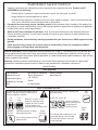
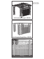
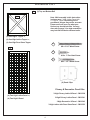
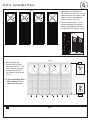
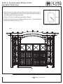
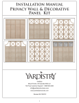
Installation Manual
Privacy Wall & Decorative
3 High Panel Kit
Yardistry
Mount Forest, ON Canada N0G 2L1
Toll Free Customer Support: 1.888.509.4382
[email protected]
www.yardistrystructures.com
Revised 04/19/2012
1
!Important Safety Notice!
•
Yardistry components are intended for privacy, decorative and ornamental use only. Product is NOT
INTENDED for the following:
- A safety barrier to prevent unsupervised access to pools, hot tubs, spas, or ponds.
- Safety railings for elevated platforms or decks.
- As load bearing support for a building, structure, heavy objects or swings. - Used in structures that trap
wind, rain or snow that would create extra load on the product.
•
Permanent structures may require a building permit. As the purchaser and or installer of this product you
are advised to consult local planning, zoning, and building inspection departments for guidance on applicable
building codes and or zoning requirements.
•
Wood is NOT flame retardant and will burn. Grills, fire pits and chimneys are a fire hazard if placed too
close to a Yardistry structure. Consult user’s manual of the grill, fire pit or chimney for safe distances from
combustible materials.
•
During installation, follow all safety warnings provided with your tools and use OHSA approved safety
glasses.
•
Some structures may require two or more people to install safely. Check for underground utilities
before digging or driving stakes into the ground!
General Information: Wood components are manufactured with Cedar (C. Lanceolata) which is protected with
factory applied water-based stain. Knots, small checks (cracks) and weathering are naturally occurring and do
not affect the strength of the product. Annual application of a water-based water repellent sealant or stain will help
reduce weathering and checks.
Keys to Assembly Success
Tools
Required
Warranty: Yardistry products are backed by a 5 year limited lifetime warranty from the date of original retail
purchase
for manufacturing defects
if installed as per •manufacturer’s
• Tape Measure
• #1, #2 and
& #3 Phillips
Open End Wrench installation instructions.
• 3/16” Hex Key
• Carpenters Level
• Carpenters Square
• Claw Hammer
• Standard or Cordless Drill
• Tape Measure
or Robertson Bits
(7/16”, 1/2” & 9/16”)
Patents Pending
or Screwdriver
• Adjustable Wrench
• Ratchet with extension Tools Required
• 1/8” & 3/16” Drill Bits
(1/2” & 9/16” sockets)
• Pencil
• #2 Phillips or Robertson
Bits or Screwdriver
Part
Identification
Key
• Carpenters
Level
On each page, you will find the parts
andDrill Bit
• 1/8”
• Carpenters
Square
quantities
required
to complete the assembly
Pencil
step illustrated on that page. Here• is
a sample.
• Standard or Cordless
Drill
Symbols
• 8’ Step Ladder
• Safety Glasses
• Adult Helpers
• Safety Glasses
• Adult Helpers
2X A1 Post 2 x 4 x83”
• 8’ Step Ladder
Quantity
Key Number
Part Description, Part Size
Throughout these instructions symbols are provided
as To
important
reminders
for proper and safe assembly.
Keys
Assemble
Success
This identifies information that requires special
attention. Improper assembly could lead to an
unsafe or dangerous condition.
Use
Help
Measure
Distance
Use
Help
Check that set or assembly is properly level
before proceeding.
Pre-drill 1/8” & 3/16” Bit
Where this is shown, 2 or 3
people are required to safely
complete the step. To avoid
injury or damage to the
assembly make sure to get help!
Check that assembly is square
before tightening bolts.
Pre-drill a pilot hole
before fastening screw
or lag to prevent
splitting of wood.
Square
Assembly
Tighten
Bolts
This indicates time to tighten bolts, but
not too tight! Do not crush the wood.
This may create splinters and cause
structural damage.
Use a measuring tape to assure
proper location.
No
CAUTION – Protrusion Hazard
Use
Level
2
Yes
If Bolt protrudes
beyond T-Nut
***Shown using 4
high privacy panel
12x12 Arched Roof Pergola - YM12505
12x12 Complete Pergola Room - YM11507
Fencing
3
Material List
R
(2) Top and Bottom Rail
P_1
Note: Wall assembly in this instruction
is shown as a 2 High Lattice Panel with
a 1 High X Topper. Depending on kit
purchased, images may not be accurate.
Please see front cover for what your
final set-up should look like. You may
also refer to page 3 for what assemblies
may look like inside the different units.
S4
(4) One High X Topper or,
(4) One High Lattice Topper or,
(4) One High Faux Glass Topper
S4
S4
S7
#8 x 2 1/4” Wood Screw
P_2
S5
S4
S7
S5
#10 x 1” Pan Head Screw
S7
S7
S6
S5
#8 x 1 1/2” Wood Screw
S6
S5
S6
(6) Panel Clips
Privacy & Decorative Panel Kits:
3 High Privacy Lattice/X Panel - YM11538
(4) Two High Lattice Panel or,
3 High Privacy Lattice Panel - YM11541
(4) Two High X Panel
3 High Decorative X Panel - YM11543
3 High Lattice with Faux Glass Panel - YM11553
4
Step 1- Assemble Panels
1. Remove the upper metal connectors on both sides of P_2 - Two High_Panel. Reattach the metal connectors
to P_2 by securing the bottom two holes of the metal connectors to the top two holes on P_2 so that the metal
connectors stick out from the top. Slide P_1 – One High_Topper between the two protruding metal connectors
on the top of P_2. Attach the metal connectors to P_1. (Fig. 1A)
*Ensure Panels are oriented correctly! (Fig. 1B)
2. Secure panels with a S4 - 2 1/4” Wood
Screw the location indicated by the large
arrow in the direction of the arrow.
Note P_1
orientation of keyhole.
3.Repeat until four panel assemblies are
created.
d reattach using
n panel.
Tenga en cuenta la orientación
del agujero de la cerradura.
y vuelva a
eros
Notez l'orientation de l'encoche
en trou deserrure.
accordement et
n des deux trous
été percés à
Pilot holes to the right
Fig. 1B - Filler Strips on Bottom
of Panel!
x4
Fig. 1A
Do not remove Small Connector
P_2
No retire los conectores
Ne retirez pas les petites pièces d
raccordement.
4x
P_1
One High _Topper
4x
P_2
Two High _ Panel
4x
5
S4
#8- 2 1/4” Wood Screws
Step 2- Assemble Wall
Fig. 1
1. Assemble panels together in
configuration shown. (Fig.1) Insert
male connector into female. Slide
down until flush with
adjacent
Pautas
básicas para
el ensamblado
de
Basic Guidelines
panel
as shown. (Fig.
1A)
1 Assemble Toppers to Panels.
Instale los topes en los paneles.
for Panel Assembly
Assemblez les pièces supérieures
et les panneaux.
Basic Guidelines
for Panel Assembly
+
los paneles
Instruc
pour l'
des pa
Les assem
3
Las ilustraciones muestran
here are configurations
2. SShown
ecure
Panelsusing
with
S4 -Cut
2con1/4”
pièces supé
configuraciones
topes.
También
Instructions
and
attach
T
a de
Topper. 2base
and 3 High Panels can
également
se pueden conectar 2 y 3 paneles
also be connected
together as
screws
provided
in
pre-drilled
à deux ou à
pour l'assemblage
altos
a
medida
que
se
adquieran.
purchased.
*Use
tornillos
de acero inoxidable
Corte
y fije(vendus
los sér
holes
as indicated
bylos arrows,
in
*Use 2 1/4" stainless
steel screws
des panneaux
de 2 1/4" que se incluyen en el juego *Utilisez les
included in the Panel Clip set to
2-1/4
po fou
sujetadores de (Fig.1)
paneles para
the
direction
of (Maximum
thede arrow.
secure
and
strengthen
theside.
assembly.
Panels
side by
3 wide x 3 high)
B. Assemble
fixations po
Les assemblages
illustrés
comportent
des
Pautas básicas para
el ensamblado de
los paneles
=
reforzar el ensamblado.
Taillez et fixez
de renforcel
Shown here are configurations using Las ilustraciones muestran
pièces
supérieures.
Il
est
Conecte
lospossible
paneles
lado a lado.
Instructions
de
base
Cut and attach
configuraciones
con
topes.
También
Pautas
básicas
para
a Topper. 2 and 3 High Panels can
Assemble
by side.
également
d'assembler
One
Wide
Anch
Assemblez
les panneaux
panneaux côte
à côte.Panels side
2des
pour l'assemblage
se
conectar 2 y 3 paneles
elpueden
ensamblado
de
Basic
Guidelines
also
be connected
together as
Conecte
los
paneles
lado
a lado.
Fig.
1A
Corte
y
fije
los
à
deux
ou
à
trois
carreaux
de
hauteur
20"
des
panneaux
altos
medida
que
Remove Large Connectors
andareattach
using top
two se adquieran.
los
paneles
for Panel Assembly
Assemblez les panneaux côte à côte.
purchased.
factory drilled holes on panel.
séparément).
*Use
los
tornillos
de acero inoxidable (vendus
Les assemblages
illustrés comportent des
*Use
2
1/4"
stainless
steel
screws
Taillez et fixez
Las
ilustraciones
Retire
los conectores grandes
y vuelva a instalarlos muestran
les vis en acier
inoxydable
Shown here are configurations
usando losusing
dos agujeros
pretaladrados
del panel.
de
2 1/4" que
se incluyen
enTambién
el juego *Utilisez
pièces supérieures.
Il est
possible de
included
in
the
Panel
Clip
set
to
configuraciones
con
topes.
2-1/4
po
fournies
dans
le
nécessaire
de
Two Wide
Anc
a Topper. 2 and 3 High Panels
Retirez lescan
grandes pièces
de raccordement et fixez-les
de
de paneles para
des panneaux
One Wide
Anc
Note
Tengaégalement
en cuenta Notezd'assembler
l'orientation
secure
strengthen
thedeassembly.
nouveau au moyen des
deux
trous conectar 2 y 3 paneles
sesujetadores
pueden
fixations
pour
panneaux
afin
de
fixer
et
l'encoche
en
orientation la orientación
del de
also beand
connected
together
as du panneaureforzar
3
supérieurs
qui ont été percés
el
ensamblado.
à
deux
ou
à
trois
carreaux
de
hauteur
trou de
serrure.
of keyhole. agujero
de
la
20"
altos a medida que se adquieran. cerradura.
à l'usine.
de
renforcer
l'assemblage.
purchased.
(vendus
séparément).
*Use los tornillos de acero inoxidable
*Use 2 1/4" stainless steel screws
de 2Panels
1/4" que se
incluyen
en el juego *Utilisez les vis en acier inoxydable de
Three Wide Anc
Assemble
side
by side.
included in the Panel Clip set to
2-1/4 po fournies dans le nécessaire de
Two Wide
Anc
secure and strengthen the assembly. de sujetadores de paneles para
Insert male into female. Slide down until flush with adjacent panel
3
Conectereforzar
los paneles
lado a lado. fixations pour panneaux afin de fixer et
el ensamblado.
Introduzca el extremo macho en el extremo hembra.
Deslícelo
ha
3. Connect
last asse
de renforcer l'assemblage.
3
2
2
Assemblez les panneaux côte à côte.
Assemble Panels side by side.
Conecte los paneles lado a lado.
abajo hasta que quede al ras del panel adyacente.
Insert male
into
Slide down
until
with
Insérez
les female.
pièces de raccordement
mâles
dansflush
les pièces
Four
Wide
Three
Wide
adjacent
depanel.
raccordement femelles. Faites glisser le panneau
vers le bas jusqu'à ce qu'il soit au même niveau que
Introduzca
el extremo
le panneau
adjacent. macho en el extremo hembra.
Anc
Anc
Deslícelo hacia abajo hasta que quede al ras del
panel adyacente.
Do not remove Small Connectors.
ez l'orientation
encoche en
3. Secure R-Top and
de serrure.
Assemblez les panneaux côte à côte.
No retire los conectores
Insérez les pièces de raccordement mâles dans les
pièces de raccordement femelles. Faites glisser le
panneau vers le bas jusqu'à ce qu'il soit au même
R Four
Ne retirez pas les petites pièces
niveau que le panneau adjacent.
de raccordement.
Fig.
2
pequeños.
Note wood piece at bottom prevents
collection of water.
Bottom Rails to Panel Note que la pieza de madera inferior
evita la acumulación de agua.
Assembly with S4 - 2 1/4”
Prenez note que la pièce en bois
au bas de chaque élément
ez l'orientation
Wood Screws locations située
de l'assemblage empêche
l'accumulation d'eau.
'encoche en
u de serrure. indicated by arrows in
Secure with Screws*. Use factory drilled holes.
the direction of the arrow.
Asegure el ensamblado usando tornillos*. Use los agujeros pretaladrados.
Insert
male
into
female.
Slide
down
until
flush
with adjacent panel.
(Fig. 2)
Fixez l'assemblage au moyen de vis.* Servez-vous des trous prépercés à l'usine.
Wide
Anc
Los torn
y se incluyen
*Les vis sont celles de 2-1/4 po en acier inoxydable qui sont fournies dans le
Introduzca el extremo macho en el extremo hembra.
Deslícelo
hacia
3. Connect
last assembled
panels to make a fence section.
abajo hasta que quede al ras del panel adyacente.
**R- Top and Bottom Rails
will overhang
1/4”
Insérez les pièces
de on
raccordement
dans lesSlide
pièces
Insert malemâles
into female.
down until flush with adjacent panel.
either
side of panel.
de raccordement
femelles. Faites glisser le panneau
panel_cap_labels_19x9.5.indd 7
all Connectors.
tores
petites pièces
mall Connectors.
ctores
petites pièces
2x
R
y drilled holes.
pretaladrados.
ercés à l'usine.
male
connector
the
connectors
from the outside of the
el extremo
macho en el extremo hembra.
Deslícelo
hacia
3. Connect
last assembled
panels
tomale
make
a fence section.
C. Remove
vers le bas jusqu'à ce qu'ilIntroduzca
soit au même
niveau que
conector
panel assembly.
Top and Bottom Railmasculino
will
abajo
hasta
que
quede
al
ras
del
panel
adyacente.
le panneau adjacent.
Quite los conectores masculinos deloverhang
exterior de1/4"on
la
either
side.
connecte
asamblea de panel.
mâle
Attach Top with Screws*
Insérez les pièces de raccordement mâles dans les pièces
Enlever les connecteurs mâles de l'extérieur
throughde
factory drilled holes.
de raccordement femelles. Faites glisser le panneau
l'assemblée de panneau.
short male
On Bottom, space Screws*
connector
vers le bas jusqu'à ce qu'il soit au même niveau que
4"Top
from
edges
of
panels.
and R
Bottom Rail will
le panneau adjacent.
conector
overhang 1/4"on either
side.
masculino
corto
Attach Top with Screws*
through factory drilled
holes.
le connect
mâle court
On Bottom, space Screws*
4" from edges of panels.
1/4"
Top & Bottom Rail - 78 1/2”
24x
S4
#8- 2 1/4” Wood Screws
Screws* are 2 1/4" stainless
steel included in Panel Clip set.
6
Los tornillos* son de acero inoxidable de 2 1/4"
y se incluyen en el juego de sujetadores de paneles.
1/4"
1/4"
1/4"
Step 3- Installing Panel Clips
1. Postition Panel Clips in locations indicated in Figures 1 and 1A. Orient Panel Clips according to whether
you want them to be visible or not. (i.e facing inside or facing the outside.)
2. Panel Clips should be placed in the centre of the post or the leading edge of the clip should be 1 3/8” or 3.5cm
ilC lepost
naP n
oitshown
isop dnain
edFig.
is sti 2.
no tsoP 4x4 -P ecalp 1.
ecOn
afruas flat
tafl surface
a nO .1 place P- 4x4 Post on its side and positio
away from the sidenniiofssppthe
as
ilC lenaP noitisop dna edis sti no tsoP 4x4 -P ecalp ecafrus tafl a nO .1
dnei tsnpeiliCroleenraaPsn
poiliC
rudsisnsEti.n
Ao1 tdsnoaP 14xs4er-uPgieFca
nlipde
e1.
cfOn
nfloaitindicated
ancOol.1 place
in Figures
and 1A.
Ensure
Panel
Cl
tisloepnadP
naee
ctaalocations
ridunsiatsaflat
surface
P- 4x41Post
on its
side and
positio
deplace,
tneiro era spilscrew
C lenaP erusnwith
E .A1 dna 1 seand
rugiFm
nirdgeatiaDas
cindholes
nn
i snoohiwith
tain
csoaDiagrams!
l
3. With Panel Clips din
bit.1(Not
provided)
etneiro ermark
a spilC lenaPholes
erusnE .A1adnpencil
a 1 serug!is
F pre-drill
na
i detacilocations
dnishown
i sw
noitasindicated
co
l a 1/8”
in drill
Figures
and 1A.
Ensure Panel C
!smargaiD ni nwohs sa
!smargaiD ni nwohs sa
hh
t tforoed
/3e1bedbludo2.
lh
uof
hsthe
spiplC
iclip
lcClips
o.2 bebe
1 3/8”
or 3.5cm
away from
thepost
sideoro
egdesa
gntsidoapee
le
tsisopehethm
t foorfeyrtanw
eca emhct5n.i3dreoc”a8lp
soPanel
leenhshould
at Pfshould
placed
in the centre
of the
Fig. 1A
sa tsop eht fo edis eht morf yawa mc5.3 ro ”8/3 1 eb d1..lu
o.h
siFapnflat
ilicin
ew
hot hfos2. place P- 4x4 Post on its side and positio
On
surface
2
g
n
shown
Fig.
sa tsop eht fo edis eht morf yawa mc5.3 ro ”8/3 1 eb dluoof
hsthe
pilcclip
ehtshould
fo
be 1 3/8” or 3.5cm away from the side o
.2 .giF ni nwindicated
ohs
in Figures 1 and 1A. Ensure Panel Cl
.s2plocations
gCiFlenn
ianP
wh
oFig.
s 2.
in
llird-erp dna licnep a htiw seloh wercs kram ,ecalp ni 3.
i.lshown
thClips
iW
.3 in place, mark screw holes with a pencil
With
Panel
as
shown
in
Diagrams!
llird-erp dna licnep a htiw selohdweedrivco
s kratomN,(e.ctia
lp ni s8p/holes
i1lCalehntwith
P htlioW
iaw
h.3.3 drill
1/8”
bit. (Not
provided)
llird-erp dna licnep a htiw seloh)w
ercs krp
ram ,ecablpllnirids”p
lenaPanel
P sheta
iW
3.ilC
With
Clips
in place,
mark
screw holes with a pencil
)dedivorp toN( .tib llird 2.
”8/Panel
1 a htiClips
w seloshould
h
bebit.
placed
in
the centre of the post or t
)
d
e
d
i
v
o
r
p
t
o
N
(
.
t
i
b
l
l
i
r
d
”
8
/
1
a
h
t
i
w
s
e
l
o
h
holes
with
a
1/8”
drill
(Not
provided)
1 x 8# -7S htiw A1 dna 1 erugfi ni detacidni snoitacol ni spi4.
lCSecure
lenaP ePanel
ruceSClips
.4 in locations indicated in figure 1 and 1
the
1 x 8# -7S htiw A1 dna 1 erugfi ni detacidni snoitacol ni spiw
lCeof
lrecn
adwood
Poclip
ew
rushould
eS .4 be 1 3/8” or 3.5cm away from the side o
”cscrews.
1/2”
1 x 8# -7S htiw A1 dna 1 erugfi ni detacidni snoitacol ni sp.islC
eSecure
nsaP
eoin
ru
cFig.
e2S/12.
.4
4.lshown
Panel
Clips in locations indicated in figure 1 and 1
.swercs doow ”2/1
1 3/8”
.swer1/2”
cs dowood
ow ”2screws.
/1
3. With Panel Clips in place, mark screw holes with a pencil
(3.5cm)
Top View
holes with a 1/8” drill bit. (Not provided) Top View
weiV poT
Pre-drill holes and secure withweS7iV p#8
oT x
4. Secure Panel Clips in locations indicatedTop
in figure
View 1 and 1
1 1/2” Wood ScrewsweiV poT
1/2” wood screws.
1. On a flat surface place P- 4x4 Post on its side and positio
locations indicated in Figures 1 and 1A. Ensure Panel Cl
Top View
as shown in Diagrams!
as
in
Diagrams!
egin
delocations
gnidael ehtindicated
ro tsop ehtinfofigure
ertnec 1ehand
t ni d1A
ecawith
lp eb S7dlu2.ohPanel
s sshown
lena
Pwood
.2 be
Clips
should
placed in the centre of the post or t
4. Secure Panel Clips
#8
xpil1C
1/2”
screws.
egde gnidael eht ro tsop eht fo ertnec eht ni decalp eb dluohs spilC lenaP .2
D
Fig. 1D
D
C
C
C
B
B
B
A
A
A
A
A
B
B
2. Panel Clips should be placed in the centre of the post or t
of the clip should be 1 3/8” or 3.5cm away from the side o
shown in Fig. 2.
3. With Panel Clips in place, mark screw holes with a pencil
holes with a 1/8” drill bit. (Not provided)
A
B
4. Secure Panel Clips in locations indicated in figure 1 and 1
1/2” wood screws.
weiV tnorF
weiV t57”
norF
weiV(145
tnorF
cm)
Front
57”
(145 cm)
Fron
Top View
Front
40”
)mc9.241( ”4/1 65
”4/1 65
)mc9.241( ”4/1 65
40”
(101.6 cm) )mc9.241(
A
)mc6.101( ”04
)mc6.101(
)mc6.101( ””0044
10”
(25.3 cm)
(101.6 cm)
)mc3.52(
)mc3.52(
)mc3.52(
B
10”
(25.3 cm)
Note: these clip heights are designed for a 4” ground
clearance. For ground clearance less than 4” subtract equal
number from clip heights for appropriate measurement.
12x
P
4x4 Post
6x - Panel Clips
12x S7 #8 x 1 1/2” Wood Screw
7
56 1/4” (142.9cm
56 1/4” (142.9cm
40” (101.6cm)
40” (101.6cm)
56 1/4” (142.9cm
40” (101.6cm)
(25.3cm)
(25.3cm)
Front
(25.3cm)
56 1/4”
40”
(142.9cm
(101.6cm)
Step 4- Installing Wall Into
Flat Roof Pergola
1. With the help of an adult, place the Wall on Panel Clips as shown (Fig.1)
allowing a 4” gap between the bottom of the post and the bottom edge of
the bottom rail on the panel assembly.
2. With a 1/8” drill bit, predrill holes as shown in figure 2.
INSTALLING WALL INTO FLAT ROOF PERGOLA
3. Fasten the Wall to the post and Panel Clips with a S5- 1” Pan Head Screw
provided in location of arrows. (Fig. 1)
Fig. 2. Predrill Holes and Fasten
with S5- 1” Pan Head Screw
Fig. 1
4” (10.2cm)
12x
P
4x4 Post
6x S5
8
#10 x 1” Pan Screws
Step 4- Installing Wall Into
Arched
pergolaWALL INTO ARCHED PERGOLA
INSTALLING
1. With the help of an adult, place the Wall on Panel Clips as shown (Fig.1)
allowing a 4” gap between the bottom of the post and the bottom edge of
the bottom rail on the panel assembly.
2. With a 1/8” drill bit, predrill holes as shown in figure 2.
3. Fasten the Wall to the post and Panel Clips with a S5- 1” Pan Head Screw
provided in location of arrows. (Fig. 1)
Fig. 2. Predrill Holes and Fasten
with S5- 1” Pan Head Screw
Fig. 1
4” (10.2cm)
12x
P
4x4 Post
6x S5
9
#10 x 1” Pan Screws
Step 4- Installing Wall Into Fence
1. With the help of an adult, place the Wall on Panel Clips as shown (Fig.1)
allowing a 4” gap between the bottom of the post and the bottom edge of
the bottom rail on the panel assembly.
2. With a 1/8” drill bit, predrill holes as shown in figure 2.
3. Fasten the Wall to the post and Panel Clips with a S5- 1” Pan Head Screw
provided in location of arrows. (Fig. 1)
INSTALLING WALL INTO FENCE
Fig. 2. Predrill Holes and Fasten
with S5- 1” Pan Head Screw
4.00
Fig. 1
12x
P
4” (10.2cm)
4x4 Post
6x S5
10
#10 x 1” Pan Screws