1
Abstract CPU Modeling and Refinement in Metropolis
Haibo Zeng, Qi Zhu
Department of Electrical Engineering and Computer Science
University of California, Berkeley, CA 94720
{zenghb, zhuqi}@eecs.berkeley.edu
1. ABSTRACT
We construct a parameterizable out-of-order execution and
superscalar CPU microarchitectural (timing) model based
on the Metropolis, which provides a design environment
with formal semantics. This model is strictly nonfunctional in that it only models instruction dependencies
and latencies, but doesn’t do the actual computation. This
model will be connected to a functional ISS (instruction set
simulator) that produces traces to drive it. We start with
designing an unconstrained model with a particular fetch
width, perfect speculation and no-resource constraints.
Then the model is further refined by adding in variable
latencies, realistic branch prediction, ordering constraints,
and resource constraints. This refinement will primarily
take place by adding constraints to the model, which can be
formally defined in Metropolis. The main value of this
project is to provide a proof of concept for a new
microarchitectural design space exploration methodology
based on Metropolis, which leverages: object oriented
design with formal semantics, models of computation, and
the concept of refinement in general. The abstract model
we constructed has good modularity and parameterizability.
Furthermore, it can be implemented easier than traditional
design scheme because it is based on a formal semantics.
We compare our model with SimpleScalar in the execution
cycle count. The results are close.
Keywords
CPU modeling, formal semantics, refinement, Metropolis,
instruction set simulator
2. Introduction
CPU design and modeling is a fairly tedious and errorprone process. The typical design flow is to write down a
high-level model in C or C++, then rewrite a detailed
implementation of this architecture. There is a quite large
gap between the functional description and the
implementation, since any change of the high-level model
might require the re-write of the low-level implementation.
And it is fairly difficult to do the design space exploration
in this design flow because there is no automatically
mapping between the high-level functionality description
and low-level architecture implementation.
We advocate a more formal design methodology for the
microarchitectural modeling and design space exploration.
Under the framework of Metropolis [1] which provides a
formal semantics. It also supports many kinds of model of
computations (MOC), we choose one appropriate MOC,
propose a perfectly speculative model, and then we do the
refinements to turn it into a realistic model.
The paper is organized as following: in the remainder of
this section we first provide some background information
about Metropolis, explain the single issue models that this
work is an extension of, and discuss some related work, to
show the novelty of our work. In section 3 we give an
overview of our modeling methodology. In section 4 we
first introduce our abstract two-process model and its
refinements, and then present its advantages and limitations.
In section 5 we show the comparison results with
Simplescalar on a superscalar architecture loosely based on
the Intel XScalar microarchitecture. This can prove the
correctness of our models. In the last section 6, conclusions
and future works are presented.
2.1 Metropolis
Modern-day system designs are becoming more and more
complicated, which make it harder to effectively design
them. Therefore, establishing formal design methodologies
is imperative to effectively manage complex design tasks.
This involves defining various levels of abstraction to
formally represent systems being designed, as well as
formulating problems to be addressed at and across the
abstraction levels. This calls for a design environment in
which systems can be unambiguously represented
throughout the abstraction levels, the design problems can
be mathematically formulated, and tools that can be
incorporated to solve some of the problems automatically.
Metropolis is such an environment, which provides
different kinds of model of computations (MOC) to define
the systems, and provides a formal semantics to formulate
the problems at different abstract levels.
Metropolis consists of an infrastructure, a tool set, and
design methodologies for various application domains.
In this framework, we construct a CPU model based on a
formal semantics. This can prove the feasibility of the new
methodology of CPU modeling provided by Metropolis.
The blocks of our model make up an architecture platform
for CPU modeling, which can be easily reused to help
designers to design new CPU model. This is different from
some traditional CPU model like SimpleScalar, which is
only used to simulate. Our model exploits the following
feature of Metropolis:
y
Formal Semantics
Metropolis provides a formal semantics to describe the
systems. For example, the definition of process, medium,
channel, port and so on. These semantics can greatly help
the design flow; make it more formal and less error-prone.
Also these semantics have explicit meaning in
implementation, which will make the implementation more
effectively.
y
Platform-Based Design
Metropolis is constructed based on the concept of platformbased design. A platform is an abstraction layer that covers
a number of possible refinements into a lower level. A
system can be represented at many different abstraction
levels in Metropolis. This feature can greatly help the
design re-use and regularity to the fullest extent.
y
Support many kinds of MOC’s
For different kinds of applications, it may be good to use
different kinds of MOC (model of computation), such as
FSM, data flow or Petri net. Metropolis can support many
kinds of MOC from the meta-model library. So the users
can have more choice to get faster and better design.
y
Uniform Framework
Today, the design chain lacks adequate support, with most
system-level designers using a collection of unlinked tools.
The implementation then proceeds with informal
techniques
involving
numerous
human-language
interactions that create unnecessary and unwanted
iterations among groups of designers in different
companies or different divisions. Metropolis seeks to
develop a unified framework that can cope with today's
design challenge.
2.2 Prior Work
Our models build upon ongoing work to model embedded
microarchitectures in Metropolis [11]. In this work the
XScale and Strongarm microarchitectures are modeled
using proecess networks using techniques similar to the
ones in this work. However, these models were single-issue
scalar models that can only have one pending instruction
waiting for operands (like in both the XScale and
Strongarm). This work significantly extends these models
by allowing superscalar execution with complicated
features such as reservation stations, and the notions of
refinement. The XScale and Strongarm models can be
viewed as a particular endpoint of the refinement presented
in this report.
2.3 Related Work
SimpleScalar [2] is considered to be the standard
microarchitectural simulator. It is a highly optimized Cmodel that supports the Alpha, and ARM ISA’s. Because
of the emphasis on optimization, SimpleScalar is highly
programmed at a very low level and can be difficult to
modify. Our models are at a much higher level of
abstraction, and are easier to modify and reuse. The more
important thing is that our model is not only a simulator;
the main value of it is to prove the feasibility of the new
design methodology, which can be used to guide the CPU
design more formally.
Architectural Description Languages (ADLs) such as LISA
[3] are specialized languages for describing instruction sets
and microarchitectures, but often cannot describe
microarchitectural features such as out of order execution.
The Liberty Simulation Environment LIBERTY [4]
provides a highly composable environment for constructing
cycle-accurate simulators, at a fine grain of detail. The
Operation State Machine [5] presents a model based statemachines, token managers, and four types of transactions
(allocate, inquire, release, and discard) that achieves high
performance simulations and simplifies complexity. We are
trying to make high-level abstract models that are accurate
highly reusable and simplifier to specify than the above
mentioned work. Our work is most similar to the OSM
work, and is complementary to ADL’s.
3. Our Modeling Methodology
One of the advantages from Metropolis is the clear
orthogonalization of functionality and architecture, or more
precisely, “functional specification” and “implementation
platform”, which are often defined and developed
separately, even by different groups. This separation results
in better reuse, because it decouples independent aspects,
which would otherwise be tied together, e.g. a given
functional specification to low-level implementation details,
or to a specific communication paradigm, or to a
scheduling algorithm. It is very important to define only as
many aspects as needed at every level of abstraction.
The Metropolis methodology for CPU design and modeling
can be done in the following flow, as shown in Figure 1.
platform, i.e., to select from these architecture blocks to
implementing an ISA.
Using the meta-model and formal semantics in Metropolis,
an architecture can be represented at different levels of
abstraction. For example, we may start from an abstract
speculative model which has perfect speculation for a given
fetch rate, then we assign latencies to the execution of each
instruction. After that, there are a variety of refinements
that can be done, e.g. adding non-perfect branch prediction,
limiting the number of execution blocks, and adding
memory and communication latencies. This is the synthesis
and refinement. Except this, we can do analysis and
verification, which is beyond this project.
In our synthesis and refinement, we simulate our model to
check the correctness. So far, we focus on the execution
cycle count. We will add other quantities to our simulation
in our future work.
Figure 1: CPU Modeling Methodology in Metropolis
The first step is to specify the abstract description of ISA
functionality, which is relatively independent from the
micro-architecture which will be used to implement this
functionality. This can be simply exemplified by the fact
that the same ISA can be implemented as single-issue, in-order execution microarchitecures; or multiple-issue, outof-order execution microarchitectures.
The next step consists of constructing and selecting
different architecture blocks. An architecture component in
Metropolis is defined as a set of services which specify
what it can do and how much it may cost (e.g, in time,
power, or other composite quantities). For example, we can
use a branch predictor block to model different branch
prediction schemes, and for each scheme, we can associate
it with the cost of different mis-prediction penalty. Then we
can map the functionality specification to implementation
Application
Code
Cross-GCC
ISS
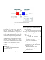
The simulation procedure we employ is pictured in Figure
2. The application code is compiled using a cross compiler.
The compiled code is then executed on a modified
instruction set simulator to generate an execution trace that
consists of an annotated trace of instructions in the order
that they were executed. The execution trace is then run on
a microarchitectural model which is specified in metropolis
using its YAPI library [6]. Modeling using YAPI library
will be explained in more detail in the next section.
The microarchitectural model executes an instruction trace,
and returns the number of cycles that it takes to execute. To
ensure accuracy the model must account for the delays of
individual instructions, the interaction between them, and
the impact of limited resources.
Exec. Trace
µArch
Model
Results
Figure 2. Simulation Procedure Overview
The execution trace is generated by the modified ISS.
When the ISS begins execution of an instruction (or
decides to not conditionally execute that instruction) it
outputs that instruction word to the generated trace file. In
addition to the instruction word, the instruction’s address
and whether or not executes is outputted the trace. Given
this trace a microarchitectural model can usually faithfully
reproduce the execution overheads without having to worry
about individual values or the locations, leading to a
greatly simplified microarchitectural model. All control
flow and conditional-execution information can easily be
obtained by examining the execution and address fields of
the trace entry. The one exception is when the time of the
execution depends on the value of the operands (e.g. taking
a short cut when multiplying by 0). The trace could be
extended to handle such value dependencies, but this would
lower simulator performance. Actually, the trace-drive
model can get the benefits from abstraction, while
sacrifices some simulation functions. We use it because the
inherent abstraction of it can meet the abstraction
requirement of our model. On the other hand, we can
modify our model to be execution-driven or other types, by
adding some blocks, such as data value resolution block.
4. Our Model
Our model utilizes meta-model and YAPI library in
Metropolis. In this section, we first introduce the semantics
of Process in Metropolis meta-model. Then we discuss our
use of YAPI channel, focusing on its extension from Kahn
Process Network MOC. After that, we will detail our
current microarchitectural models, and present the
advantages and limitations of the models.
4.1 Process
The function of a system is described as a set of objects
that concurrently take actions while communicating with
each other. We call such an object process in the metamodel, and associate a sequential program with it. A
process always defines at least one constructor and exactly
one function called thread, the top-level function to specify
the behavior of the process.
A process communicates through ports defined in the
process. A port is specified with an interface, declaring a
set of methods that can be used by the process through the
port. Different implementations of the methods provide
different ways of communication. In general, one may have
a set of implementations of the same interface, and we refer
to objects that implement port interfaces as media. YAPI
channel is one of the communication medium which we use
in our model. Any medium can be connected to a port if it
implements the interface of the port. This mechanism,
which is borrowed from object-oriented concepts, allows
the meta-model to separate computation carried out by
processes from communication among them. This
separation is essential to facilitate the description of the
objects to be reused for other designs.
4.2 YAPI
YAPI [6] is an extension of Kahn Process Networks [7]
that in addition to having processes communicating via
unbounded FIFO’s it allows for a non-deterministic select.
To synchronizing the execution of processes, the
communication channels are read-blocking, meaning a
process has to wait to read from the channel until there are
some tokens in it. Kahn Process Networks have the
property that their result is deterministic and independent
of their firing order. We use YAPI in a cyclical manner,
where each cycle every process reads one token from all of
its input channels and writes a token to each of its output
channels. In order to model a particular pipeline length,
channels are pre-filled with the number of tokens equal to
the pipeline length. As long as the cyclic assumption is
maintained the pipeline behavior is guaranteed.
Using YAPI simplifies the modeling because of the
abstraction, the synchronous assumptions, and the
guarantee of deadlock avoidance and determinism provided
by the combination of YAPI with the cyclic assumption.
4.3 Model Detail
We use a two processes model as shown in Figure 3. The
two processes include a fetch process that handles the fetch
and issue of instructions from execution trace, and an
execution process that handles the execution, operand
dependencies, and forwarding delays between instructions.
We use three kinds of YAPI channels: an issue channel
which passes the instructions from the fetch process to the
execution process, a RS_Info channel from the execution
process to the fetch process which passes information
about reservation stations, and several result channels that
model the execution process of instructions by connecting
the execution process to itself. Following we will explain
each process further.
Figure 3. Two Processes Our of Order Execution Model
4.3.1 Fetch Process
The fetch process gets the instructions from execution trace,
generated by the instruction set simulator, and then issues
the instructions to the execution process. We use a data
type called instruction group to represent a set of
instructions, which also can be just one instruction or even
none. Therefore, our model can deal with single-issue and
multiple-issue without any special change. We will first get
an instruction group which was called fetch_group from
the trace file. The number of instructions of fetch_group
usually equals to the maximum issue width except when a
branch instruction is presented in the group. In this case,
the instructions following the branch will not be included
in the group. After we get the fetch_group, we will do the
structural hazard check and choose an issue group from the
fetch group. We preserve the in-order issue, i.e., we will
not issue following instructions if one instruction is stalled
for the structural hazard. We will also consider the extra
issue cycles for some instructions. Whenever there is a stall,
we will issue an empty instruction group at that cycle.
The pseudo code of the main part of this process is shown
as follows:
while (simulation_not_end) {
Read_RS_Info();
//Read the reservation station information
if (extra_issue_stall > 0){
//extra issue stall come from some instructions
which need more than one cycles to be issued
Write_Issue_Channel(bubble_group);
//bubble group is an instruction group with no
instructions, which is written to channel when stall occurs
extra_issue_stall--;
}else{
if (inst_group_wait){
//this means there is one instruction group which
was waiting to be issued because of extra issue cycles and
now it can go, it is stored in the issue_group
Write_Issue_Channel(issue_group);
inst_group_wait = false;
}else{
if (! structure_stall){
//structure_stall means there is an
instruction group which had been fetched but has not been
issued completely because of the structural hazard from
RS, the left instructions will be stalled in the fetch_group
Get_InstGroup_from_trace();
//get the fetch_group from the trace
}
Detect_Structural_Hazard();
//detect the structural hazard in fetch_group and get
the issue_group which will be issued
extra_issue_stall = Get_Extra_Stall(issue_group);
if (extra_issue_stall == 0){
Write_Issue_Channel(issue_group);
}else{
Write_Issue_Channel(bubble_group);
extra_issue_stall--;
inst_group_wait = true;
}
}
}
cycle_count++;
y
Functional Unit
A branch predictor is integrated with the fetch process, and
the mode of this predictor can be configured. So far, a 2bits predictor or just a perfect branch mode can be chosen.
In the 2-bits predictor, we get the branch result from trace
file and update those 2-bits pattern. If a misprediction
occurs, we simply add the misprediction penalty, i.e., extra
execution cycles to the cycle count. Since we use a tracedriven model, in which the trace file has the information
that whether an instruction is really executed or not, we do
not need to simulate the flash in pipeline. More branch
predictor types can easily be added to the model because of
its modularity.
Generally, each reservation station is corresponding to a
functional unit. For the architecture which has several same
functional units, we can model it in two ways, depending
on the requirement. If there is a separate reservation station
for each functional unit, we can send the corresponding
instructions to one of them, depending on the availability
of each functional unit. In this case, one reservation station
is also mapped to one functional unit. If there is an
integrated reservation station for all these same functional
units, we can let one reservation station map to several
functional units, or we can let one functional unit map to
several same channels, which is more convenient based on
YAPI channel. If we use the latter scheme, we need to
allow multiple instructions to be dispatched to one
functional unit in the same cycle. So far in our model, only
one instruction can be dispatched to one function unit
within a cycle. We will extend it in our future work.
4.3.2 Execution Process
y
}
y
Branch Predictor
The execution process gets the instructions from the fetch
process through the channels between them. Since the fetch
process performs the structural hazard check, execution
process simply puts the instructions into corresponding
reservation stations. If the execution condition for an
instruction is satisfied, this instruction will be dispatched to
the execution pipeline, which is modeled by the Result
Channel. After the instruction goes through the Result
Channel, it will be written back if the CDB resource is
available. A CDB controller can be integrated to arbitrate
the write back. When an instruction is written back, the
information of corresponding instructions which are
waiting for the results will be updated. Also the register file
may be updated if it is waiting for the result, and the entry
for this instruction in reservation stations will be released.
This is a general flow of execution process. Following we
will describe the schemes further.
y
Reservation Station
The instructions in one instruction group will be added to
the reservation stations in program order to preserver the
data dependencies. When one instruction is added to a
reservation station entry, the fields in the entry should be
set to indicate the data dependencies for this instruction.
Also the register file needs to be updated if the instruction
writes the register file. Furthermore, we consider the
condition code, which is introduced in some instruction
sets, such as ARM. Since the condition code represents a
kind of dependency, we can deal with it in a similar way as
data dependency. For each instruction, we use a tag to
indicate which other instruction will give the condition
code to it. There is also a global register for the condition
code, which stores the tag of last instruction that will write
the condition code.
RS_Info
Every cycle, the availability information of reservation
stations is sent to the fetch process. The YAPI channel has
the blocking-reads characteristic, which can be used to
synchronize the linked processes. Therefore, the fetch
process will get the current information of reservation
stations, and use it to decide which instructions to issue. To
decide this, the fetch process needs to know the association
between instruction types and functional units, which is
sent to it from execution process at the start of the
simulation.
y
Result Channel
Result channels, which use the YAPI channel as in cyclic
way, are used to model the execution delay of functional
units. One functional unit can be mapped to several result
channels, the number of which can be configured by the
designer. Therefore, the various execution latencies for
instructions in the same functional unit can be modeled, by
setting different lengths of the result channels for this
functional unit. And as we mentioned above, several
channels mapping to one functional unit can be used to
model several same functional units.
We use the number of tokens in the channels to represent
the length of channels, which can be seen as the execution
latencies. At the start of the simulation, we will prefill the
channel with a certain number of tokens. And then at each
cycle, one token will be written to the channel while one
token will be read from the channel. Therefore, the length
of the channel will be kept during the simulation, which
will give fixed execution latency for this channel. . This
gives us much flexibility to model different ISAs: we use
an individual channel to represent each type of instructions
with different execution cycles.
y
CDB Controller
For multiple-issue architecture, more than one instruction
may complete the execution in the same cycle. If there is
no constraint on the common data bus (CDB) resource,
these instructions will all be written back in this cycle.
However, sometimes the CDB resource is limited, so we
model the constraint of write-back width, which is
proportional to the number of CDBs. We construct a CDB
controller model, which arbitrates the write-back of
instructions. When the execution of an instruction is
complete, this instruction will be read from the channel and
stored into a buffer corresponding to the channel. Then the
length of the channel can be kept and the complete
instruction will not be lost. At each cycle, the CDB
controller will choose the instructions to commit (write
back) from the buffers, which are corresponding to the
channels. The number of instructions that can be
committed, i.e., commit length, is configured by the
designer. CDB controller decides which channels should be
chosen by using an arbitration scheme. This scheme can
also be configured. So far we use a simple round-trip
scheme, in which we check the channel buffers one by one.
If a channel buffer has instructions waiting for commit and
there is still available CDB resource, the oldest instruction
will be committed, and then it turns to the next channel
buffer. When there is not any available CDB resource or all
the channels have been checked, the check will be stopped.
And next time, it will start from the stop place. Of course,
some more complicated schemes can be used to arbitrate.
For example, we could give a higher priority to those
channels whose buffers are nearly full.
//increase the cycle count, actually, we use this number
as the cycle count for all the simulation
Following is the pseudo code of the execution process.
Since we have explained some details of this process, we
will just give a very brief description of the process.
4.4.2 Easy refinement and modification
current_packet = Get_Inst_Packet_from_Fetch();
//get the instruction packet from fetch process
Add_to_RS(current_packet);
//add the instructions to reservation stations
Dispatch_to_Exectue ();
//dispatch the ready instructions to corresponding
functional units
Add_to_Commit_Queue();
//add the complete instructions to correspoding channel
buffers to wait for commitment
Write_Back();
//write back the instructions which are committed
4.4 Advantages
Our model has some advantages which can benefit the user
in the design flow.
4.4.1 Formal Semantics
Our model is based on a formal semantics provided by
Metropolis, which uses a logic language to capture nonfunctional and declarative constraints. Because the model
has a precise semantics, it can support several synthesis and
formal analysis tools in addition to simulation.
Since both the computation and the communication are
clearly defined by this formal semantics, a clear design
flow can be easily achieved in our model. Therefore, we
can make the design more quick and errorless.
Formal Semantics also makes the model easy to be
implemented in hardware. This is a big advantage over
some low-level simulator such as SimpleScalar. For
example, there is no clear correspondence from a
communication channel to a real implementation in
SimpleScalar. So the user will always be confused while
going to the final implementation. In our model, because
we have a clear semantic of what a communication channel
is, and because of the unified framework in Metropolis, we
can easily find what kind of architecture blocks to
implement it, e.g by shared memory, FIFO, or something
else.
In general, a design of what one designer conceives as the
entire system is a refinement of a more abstracted model of
a service, which is in turn employed as a single component
of the larger system. This is the built-in notion of
refinement in Metropolis. When a design is refined,
typically a sequence of event instances of the original
design corresponds to a set of sequences of event instances
of the refined one and this correspondence can be modeled
with coordination of event instances, and a set of individual
designs related in this way constitutes a hierarchy where a
part of a higher level design is related to a set of parts of
the lower designs. For CPU modeling, we make our model more
and more powerful through the refinement. The concept of
platform based design and the built-in notion of refinement in
Metropolis make this refinement process much easier than
tradition scheme.
Write_RS_Info_Channel(rs_info);
4.4.3 Reusability and Parameterizability
//send the information of reservation stations to the
fetch process
Our CPU model can be highly reused, also based on the
concept of platform-based design in Metropolis. Users can
easily parameterize their designs to test on different
configuration of architecture. Since the model is at a high
cycle_count++;
level, there are many parameters can be configured. e.g.
issue width; branch model; number of FUs; misprediction
penalty; instruction types, instruction execution time;
reservation station size. We will show an example in next
section, which lists the execution cycle count for different
issue width.
4.4.4 Unified Framework
The Metropolis meta-model is a language to specify netlists
of concurrent objects, each taking actions sequentially. The
behavior of a netlist is formally defined by the execution
semantics of the language. A set of netlists can be used to
represent different levels of abstractions or different
portions of the system being designed, where the behaviors
of the netlists can be related to each other by using metamodel constructs. This allows one to specify all the aspects
described in the previous section for conducting designs,
i.e. function, architecture, mapping, refinement, abstraction,
and platforms, using the same building blocks of the
language.
This unified framework provide by Metropolis is greatly
helpful. Users can explore the design space and implement
their designs on a uniform platform. Furthermore, our CPU
model can be extended easily in Metropolis; such as
multiple CPU's, memory system, I/O system and so on.
Above advantages can shorten the design time of processor
design, make the design process more formal and provide
the users an easy way to specify, simulate, and verify their
systems. Furthermore it enables microarchitectural design
space exploration for processing elements at the system
level.
4.5 Limitations
Our model also has some limitations as follows:
4.5.2 More blocks
For our models, some blocks need to be added to make the
models more general. We will discuss this in the future
work section. Actually, this is not an inherent limitation; it
is just the limitation of our current model, which will be
further refined in the future.
5. Experimental Results
In this section we provide some experiment results. To
verify the correctness of our model methodology, first we
take Intel XScale microprocessor as an example and
compare the simulation results of our model with
SimpleScalar, which is considered as a standard
microarchitecture simulation tool. Then to show the
effectiveness of parameterization in our model, we
parameterize our out-of-order execution model by
changing issue width and compare the impact of these
changes on the performance in terms of CPU cycles.
Because Metropolis is mainly used to design embedded
systems, we choose Mibench [8] as our test benches, which
have several characteristics suitable for embedded systems.
MiBench is a free, commercially representative embedded
benchmark suite developed at University of Michigan.
MiBench has considerably different characteristics than the
SPEC2000 benchmarks when analyzing the static and
dynamic
characteristics
of
embedded
processor
performance. The dynamic instruction profile has more
variation in the number of branch, memory, and integer
ALU operations. It also has more variable text and data
memory segment sizes, but the data tends to be more
cacheable. MiBench and SPEC2000 both have very
predictable branches. The variation in the number of
instructions per cycle also shows that the benchmarks fall
into the expected control and data intensive categories, as
in embedded system applications.
4.5.1 Performance Lost
For the design methodology, more formal usually means
the loss of some performance. This is a tradeoff in the
design: higher level of abstraction can give you more
flexibility, reusability, and provide a quicker design flow.
But this may lead to the performance loss. However, if we
can control the performance loss within a certain range, we
can get more benefits from the shorter time-to-market,
more stable systems and highly reusable. Then how can we
ensure the performance? We can utilize the concept of
platform based design, i.e., transfer the quantity estimation
from the lower level to the higher level, and then we can
choose the mapping which will give our better performance.
Another question is how to test our performance. We will
explain it in the Implementation part in next section.
5.1 Comparison with SimpleScalar
We choose to model architectures based on the ARM ISA
[9] because it features a simple and powerful instruction set
that is popular in embedded systems. In particular, we
model the Intel XScale PCA-255 processor [10], which is a
successor to the famous StrongARM. It implements versio
5 of the ARM ISA with thumb extensions and several
custom instructions implemented as a coprocessor. Like the
StrongARM, the XScale is a scalar processor, which has a
7 stage execution pipeline, dynamic branch prediction, and
out-of-order commitment. It has an issue channel length of
4. For detailed configuration of XScale, please refer to
Appendix.
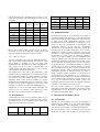
The results is shown in Table 1. From it, we can see that
averagely the timing accuracy of our model with respect to
SimpleScalar is about 3% according to our measurements.
As an architecture modeling tool which will be used in
high-level design space exploration, the accuracy of our
model is good enough. This exemplified the correctness of
our model.
Testbench
#Inst.
SimpleScalar
Our
model
Relative
Error
fft
15460
22133
20897
20612
tiffdither
22696
33207
30462
30107
ispell
41936
61326
60040
60001
madplay
148674
193016
182319
179681
search
187422
260022
235742
231819
rijndael
15146
21662
20234
-6.6%
fft
15460
21994
20612
-6.3%
tiffdither
22696
30555
30107
-1.5%
5.3 Implementations
ispell
41936
59175
60001
1.4%
madplay
148674
178881
179681
0.4%
search
187422
238402
231819
-2.8%
It would be interesting if we could show some results of
real implementation and compare its cost functions with the
results of current design flows. But we are still on the way
of going to the final implementation because of the
incompleteness of the infrastructure in Metropolis. As in
section 2, after the specification of functionality and
architecture platform, we will map the functionality
specification to an appropriate architecture, namely the
mapping step in the whole design flow. Now we have
finished the execution model of quantity requests and
resolutions, i.e. the semantics to annotate a specific number
of quantities (e.g, time, power, or composite quantities)
with an event. This semantics of event coordination with
respect to quantities play a key role in the design flow. First,
architecture is defined as a platform which provides a set of
services and how much these services cost. It is necessary
to support the event coordination mechanism to annotate
specific cost to the services. Second, mapping is actually
the coordination between the execution of function and
architecture networks. Third, a refinement through event
coordination provides a platform because (1) when a
design is refined, typically a sequence of event instances of
the original design corresponds to a set of sequences of
event instances of the refined one and this correspondence
can be modeled with coordination of event instances, and
(2) a set of individual designs related in this way
constitutes a hierarchy where a part of a higher level design
is related to a set of parts of the lower designs.
Average
3.2%
Table 1: Cycle Count Comparison
But we still can make it more accurate. We try to analyze
the sources of errors in the remainder of this section, and
leave the possible modifications to the next section.
5.1.1 Sources of errors
The first possibility comes from the different abstraction
level of our model and SimpleScalar. Our model is YAPI
based, which is focusing on the very high level
functionalities and communications. While SimpleScalar is
fairly lower level. So it is hard to configure these two
models exactly the same, since there is no one-to-one
correspondence of the functional blocks.
The second source is the lack of value dependency in the
generated trace file. Although given an execution trace our
microarchitectural model can usually faithfully reproduce
the execution overheads without having to worry about
individual values or the locations, leading to a greatly
simplified microarchitectural model, an exception is when
the time of the execution depends on the value of the
operands (e.g. taking a short cut when multiplying by 0).
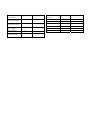
Table 2: Parameterizability Results
Furthermore, so far we deal with branch mispenalty and
memory access very roughly, which will lead to some
inaccuracy. We will improve this in our future work.
Now the formal semantics to support the mapping
constraints are still under construction. So the step to final
implementation can not be done in the near future. We
leave this part in the future work.
5.2 Parameterize
6. Conclusions and Future Work
As mentioned in section 4, in our abstract model, we can
easily parameterize our design. Following Table 2 shows
the different cycle count of different issue width, from
single issue to 4 instructions per cycle.
Testbench
rijndael
#Inst.
15146
Width=
1
Width=
2
Width=
3
22103
20733
20234
6.1 Conclusions
Through our CPU modeling, we prove the feasibility of
constructing CPU models by a new design methodology
based on Metropolis. This methodology is more formal,
more abstract, more modular, and more parameterizable.
We also presented a variety of techniques for easing and
automating the design and modeling of microprocessors.
And the blocks of our model can be reused in new CPU
model design.
Our model can also be a simulator, which can be
configured easily and provides a close estimation at a high
level. This will be greatly helpful to the design space
exploration, because current design complexity requires the
early stage estimation more and more. We compared our
results with SimpleScalar to validate the accuracy of our
model, taking the ARM instruction set as an example. The
results show that the average error with respect to
SimpleScalar is about 3%, which is acceptable as a highlevel model. Therefore, our model can be directly used in
early stage of design space exploration in system-level
design.
6.2 Future Work
There are lots of work can be done in the near future. First,
our model itself is incomplete. We can add models of
memory systems, interruptions and exceptions. Also more
functional blocks can be modeled and added to our
architecture library, such as more branch prediction
schemes, out-of-order issue and so on.
Second, as mentioned in section 5.3, we do not show any
results about the costs of final implementation because the
infrastructure of Metropolis is still under development. But
as the final goal of Metropolis, we are looking forward to
some exciting results to show the advantage of both our
model and Metropolis. Therefore, we will try going deeply
into the real implementation in future work. Before that, we
will first add the quantity resolution to estimate some other
quantities, such as area and power.
[4] M. Vachharajani, N. Vachharajani, D. Penry, J. Blome,
and D. August, “Microarchitectural Exploration with
Liberty,” Proceedings of the 35th International
Symposium on Microarchitecture, November, 2002.
[5] W. Qin, S. Malik. “Flexible and Formal Modeling of
Microprocessors with Application to Retargetable
Simulation,” Proceedings of 2003 Design Automation
and Test in Europe Conference (DATE 03), Mar, 2003,
pp.556-561.
[6] E. A. de Kock, G. Essink, W. J. M. Smits, P. vd Wolf,
J.-Y. Brunel, W. M. Kruijtzer, P. Lieverse, K. A.
Vissers, “YAPI: Application Modeling for Signal
Processing Systems,” Proceedings 2000. Design
Automation Conference, pp.402-405
[7] G. Kahn, “The Semantics of a Simple Language for
Parallel Programming, in Information Processing,” J.L.
Rosenfeld, Ed. North-Holland Publishing Co., 1974.
[8] Matthew R. Guthaus, Jeffrey S. Ringenberg, Dan
Ernst, Todd M. Austin, Trevor Mudge, Richard B.
Brown,
“MiBench:
A
free,
commercially
representative embedded benchmark suite,” IEEE 4th
Annual Workshop on Workload Characterization,
Austin, TX, December 2001.
[9] ARM Ltd. “ARM Architecture Reference Manual,”
DDI 0100D edition, 2000
[10] Intel Corporation, Santa Clara, CA. “Intel Xscale
Microarchitecture User’s Manual,” 2003
ACKNOWLEDGEMENTS
[11] T;
Meyerowitz,
A.
Sangiovanni-Vincentelli.
“Modeling the XScale and Strongarm Processors using
YAPI”, SRC Deliverables Report, Task 837.001, April
30,
2003;
Available
at:
http://wwwcad.eecs.berkeley.edu/~tcm/projects.html
We thank Trevor Meyerowitz for invaluable mentoring
during the project.
Appendix
REFERENCES
[1] F. Balarin, Y. Watanabe, H. Hsieh, L. Lavagno, C.
Passerone, A. Sangiovanni-Vincentelli, “Metropolis:
An
Integrated
Electronic
System
Design
Environment,” Computer Magazine, April 2003, p. 4552
[2] D. Burger, and T.M. Austin, “The SimpleScalar
Toolset Version 2.0,” Tech Report. 97-1342,
Department of Computer Science, University of
Wisconsin-Madison, June 1997.
[3] S. Pees, A. Hoffmann, V. Zivojnovic, and H. Meyer,
“LISA – Machine Description Language for Cycleaccurate
Models
of
Programmable
DSP
Architectures,” Proceedings 1999. Design Automation
Conference, pp.933-938.
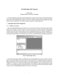
Here we list the appendix table to show the issue and result
delay (in CPU cycles) for instructions on the Intel XScale
PXA-255 microarchitecture. Question marks indicate that
we are not sure about the given values.
Instruction
Desription
Issue Delay
Result Delay
Data
processing
shift amount literal
1
0
Data
processing
shift amount for
register
2
0
Mul or Mul/Add
giving 32-bit result
1...4
0…3
Mul or Mul/Add
giving 64-bit result
?
?
Load single – writeback of base
1
0
Branch or branch
and link
1(5)
0
Load single – load
data zero extended
1
2
MCR
4(7)
4(7)
MRC
2(7)
N/A
Load single – load
data sign extended
1
2
MSR to control
2(6)
0
Store single – writeback of base
1
0
MRS
1
1
Swap
5
0
Load multiple
3…23
1…3
SWI
6
0
Store multiple –
write-back of base
3…18
0