1
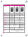
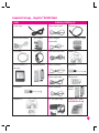
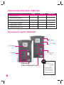
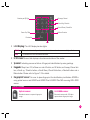
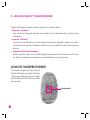
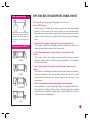
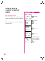
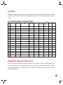
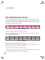
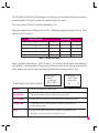
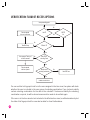
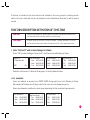
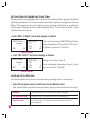
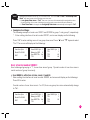
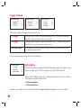
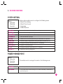
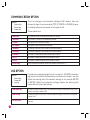
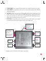
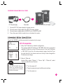
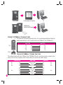
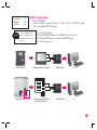
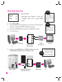
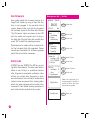
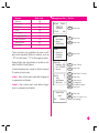
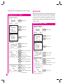
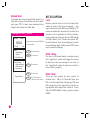
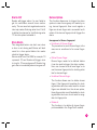
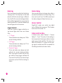
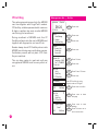
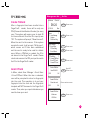
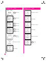
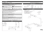
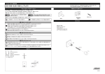
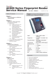
AC800 • AC800 PLUS • AC800 PLUS MC SERIES
&DOOR ACCESS CONTROL SYSTEM
HARDWARE USER MANUAL
FINGERPRINT TIME ATTENDANCE
For technical tips and manuals in other languages, refer to http://user.fingertec.com
Please register your FingerTec® reader for an extended 2 months to a total of 14 months warranty at
www.fingertec.com
C
2008 FingerTec Worldwide Ltd. All rights reserved.
AC800 • AC800 PLUS • AC800 PLUS MC SERIES
& DOOR ACCESS CONTROL SYSTEM
HARDWARE USER MANUAL
FINGERPRINT TIME ATTENDANCE
COPYRIGHT NOTICE
All rights reserved. No part of
this book may be reproduced or
transmitted in any form or by any
means, electronic or mechanical,
including photocopying, recording, or by any information storage
and retrieval system, without written permission from FingerTec
Worldwide Ltd. Every precaution
has been made to supply complete and accurate information.
Information in this document is
subject to change without prior
notice.
DISCLAIMER
No person should rely on the
contents of this publication without first obtaining advice from a
qualified professional person. The
company expressly disclaims all
and any liability and responsibility
to any reader or user of this book,
in respect of anything, and of the
consequences of anything, done
by any such person in reliance,
whether wholly or partially, upon
the whole or any part of the contents of this book.
FINGERTEC WORLDWIDE LTD
For enquiries on technical matters, please forward the
email to
[email protected]
CONTENTS
1 • GETTING STARTED
Introduction to FingerTec AC800 Models
• Complete Package - FingerTec AC800 Models
• Materials Provided with FingerTec AC800 Models
• Basic Features of FingerTec AC800 Models
7-11
2 • USING THE FINGERTEC® FINGERPRINT READER
12-21
3 • ACCESS OPTIONS
22-31
Using the Fingerprint Reader
Tips for Best Fingerprint Enrollment
Initial Set Up of the FingerTec® Fingerprint Reader
• Date/Time Adjustment
• Enrollment
• Enrollment of Supervisor/Administrator
• Enrollment of Normal User
• Fingerprint Verification
• Password Enrollment
• Password Verification
• Deleting Users
Brief Introduction to Access Options
Verification Flow of Access Options
Function Description Definition of Time Zone
Definition of Grouping Function
User Access Options
Access Comb
Dsen. Delay (Door Sensor Delay)
Dsen. Mode (Door Sensor Mode)
Dsen. Alarm (Door Sensor Alarm)
Duress Options
Management of Duress Fingerprint
4 • THE OTHER FUNCTIONS
31-33
5 •INSTALLATION & COMMUNICATIONS
34-44
System Option
Power Management
Communication Option
Log Option
Auto Test
System Info
(For FingerTec Installer)
Connections Available
Startup and Shutdown
Communication Connection
DOOR LOCK CONNECTION
6 •THE OTHER FUNCTIONS
(AC800 PLUS/AC800 PLUS MC)
45-60
For AC800 Plus/AC800 Plus MC
Advanced Options
• Turn Off Alarm • Upd Firmware • Work Code • Button Beep
Pendrive MNG
• Download Attendance Log • Download User • Upload User
Access Options
• Lock • DSEN. Delay • DSEN Mode • Alarm CNT • DSEN Alam
• Duress Option • Help Key • Duress Delay • Access Control • Setup Lock Function
For AC800 Plus MC only
Advanced Options • Card Only • FPCard Key
FP Card MNG • Create PINCard • Enroll FPCard • Create FPCard • Reg FPCard
• Unreg FPCard • Empty FPCard • Dump FPCard • Move TO FPCard
APPENDIX • TROUBLESHOOTING
61-64
1 • GETTING STARTED
INTRODUCTION TO FINGERTEC® AC800 MODELS
The FingerTec® AC800 models are bestseller models, which function to record time and attendance and to control access. For FingerTec® AC800 models there are three series available.
AC800 is the standard unit, AC800 Plus is the high-end unit and AC800 Plus MC is the high-end
unit with a card function. The differences of the AC800 models are tabulated in page 8.
7
Specifications
Model
Model AC800
AC800 Plus
Functions
Time Attendance & Door Access System
Series available
AC802, AC803
FP template capacity
1,500 (AC802)
2,800 (AC803)
Transaction storage
100,000 (AC802)
150,000 (AC803)
Connections
AC802
AC802
1,500
50,000
30,000
TCP/IP, RS232,
RS485
TCP/IP, RS232,RS485,
USB Flash Disk
Subnet mask &
a gateway option
Not available
Available
Work code function
Not available
Card reader
Available
Not available
MiFare Card
Not applicable
4000 users if no
fingerprint templates
are stored inside reader
Card capacity
Sensor type
Software language
available
8
AC800 Plus MC
Optical sensor
with silicon coating
URU 4000B Module
with silicon coating
English, Arabic, Chinese Simplified, Chinese Traditional, French,
German, Indonesian, Malay, Russian, Farsi, Portuguese, Spanish,
Thai and Vietnamese.
Complete Package - FingerTec® AC800 Model
AC800
AC800 Plus/AC800 Plus MC
Power cable
Power supply cable 2
USB extention
RS485 cable extender
3-pin adapter
26-bits wiegand
output cable
TCMS V2 software dongle
RJ45 cable
RS232 cable
Door accessories cable
Software CD
RS232 connector
Screwdriver
Power supply cable
USB pen drive
Screwdriver
RS485 connector
Wireless
doorbellC
Software CD
DC 12V power supply
Communication I/O
controller
Wireless doorbellC
MIFARE Card (1 piece)
For AC800 Plus MC only
9
Materials provided with FingerTec® AC800 Model
Quick Start Guide
Hardware User Manual
AC800
√
AC800 Plus
√
AC800 Plus MC
√
√
√
√
Software User Manual
√
√
√
Video Guide for Hardware
√
√
√
Video Guide for TCMS V2
Sample of enrollment form
√
√
√
√
√
√
Basic Features of FingerTec® AC800 Model
• 2 Speaker
• 3 L.E.D. Display
1 LCD Display •
4 Keypads •
• 5 Fingerprint
Sensor
Note
AC800 Model •
AC800 Plus/AC800 Plus MC Model •
Fingerprint Sensor
(URU 4000 Sensor)
Card Induction Area
(AC800 Plus MC only]
10
Number pad (0-9) •
• Escape/Cancel
• Scroll Up/Check-In
• Scroll Down/Check-Out
Power On/Off •
• Menu Function
Doorbell •
• OK
1 L.E.D Display: The L.E.D display has two lights.
Green
The reader is in standby mode or to indicate that user has been successfully verified.
Red
To indicate that user verification has failed.
2 LCD Screen: Screen that displays instructions and status of the reader.
3 Speaker: Indicating success or failure of fingerprint identification by voice greetings.
4 Keypads: Keys from 0-9, a Power on and off button, an OK button, an Escape/Cancel button, a Scroll up/ Check-In button, a Scroll Down/Check-Out button, a Doorbell button and a
Menu button. Please refer to Figure 1.2 for details.
5 Fingerprint Sensor: For user to place fingerprint for identification/verification. AC800 is
using optical sensor and AC800 and AC800 Plus & AC800 Plus MC are using URU 4000
sensor.Types of scanner
TYPES OF SCANNER
Optical scanner
Standard scanner to capture fingerprint
image
U.r.U 4000 scanner
Enhanced scanner with 512dpi to
capture better fingerprint image
11
2 • USING THE FINGERTEC® FINGERPRINT READER
FingerTec® fingerprint reader provides 3 types of enrollment method:
• Fingerprint Enrollment
User enrolls his fingerprint template into a reader and the template will be used for future
verifications.
• Password Enrollment
For user who has difficulty to enroll his fingerprint due to poor fingerprint quality, he is recommended to enroll password. Password enrollment is also suitable for visitors and temporary
workers.
• Fingerprint and Password Enrollment
Under this option, a user can enroll both fingerprint and password at the same time. The user
can either use fingerprint or password to report attendance or to gain access.
USING THE FINGERPRINT READER
This chapter will guide on how to use the
FingerTec® fingerprint reader effectively.
To get a good reading every time, a fingerprint enrollment for the first time must be
done properly.
• Center points
12
What you should do
TIPS FOR BEST FINGERPRINT ENROLLMENT
There are 5 tips to get good fingerprint enrollment:
• Use INDEX finger
Place finger flat on the fingerprint sensor. Make sure the
finger’s midpoint is placed at
the center of the fingerprint
sensor.
What you should NOT do
Index finger is smaller than thumb and it can be comfortably
placed on the sensor. The use of thumb is not recommended
because the center points might not be placed properly on the
sensor, hence cannot be read by the sensor due to its larger
size.
• Make sure the finger is not wet, too dry, injured or dirty
The finger needs to be slightly moist to enable the sensor to
read the minutiae points on the fingerprint.
• Place the center points of your finger at the center of the
sensor
UPRIGHT
The center points of a finger is an area where there is a swirl
and the center points must be properly placed on the sensor
during enrollment.
• Don’t press hard at the sensor, just place your finger on the
sensor
ASKEW
The sensor is reading minutiae points of your finger and placing
a finger properly on the sensor will prompt the sensor to read
those points. Pressing your finger hard on the sensor is not
necessary.
• Don’t do enrollment under bright light or direct sunlight
OFF CENTER
It is important to note that bright light or sunlight could interfere with the reading of the sensor. Avoid placing the reader
under direct sunlight or bright light to avoid difficulty in enrollment and future verification.
PART
13
INITIAL SET UP OF THE
FINGERTEC® FINGERPRINT
READER
Date/Time Adjustment
When first installing the FingerTec® fingerprint
reader, it is important to set the correct date and
time.
Follow the steps below to access the Date/Time
adjustment menu:
When you see this
Welcome
Check-In
08:24
07-01-08
MENU
Press once
6
Press once
OK
Press once
OK
Press once
OK
Press once
Mon
User Manage
4 Options
Sys Info
4 System Opt
Power Mng
Comm Opt
4 Date Time
Language
ENG
Fmt DD-MM-YY
YY-MM-DD
24H
2008-1-17
08:24:25
ESC
OK
14
| Do this
Use the keypad to key in the
year, month and date. Scroll
down more to change the
day, hour, minute and seconds
OK
Press once
Enrollment
To assist in fingerprint enrollment, we have designed a form for the administrator to use to keep
track of the enrollment detail or you can design your own form to suit to your company’s requirements.
User Enrollment Template Form for FingerTec® Reader
No.
User ID
Employee No.
Name
Department
Reader ID:____________________
IC No.
No. of Fingers
Enrolled
Date
Registered
Note
Signature
Enrollment of Supervisor/Administrator
Once the FingerTec® fingerprint reader is switched on, a display on the screen will appear. First,
to enroll a supervisor or an administrator, who is the in-charge person to administer the fingerprint templates and the transaction data in the FingerTec® reader. Choose trustworthy people
for this particular role.
15
When you see this
Welcome
| Do this
Check-In
08:24
07-01-08
MENU
Press once
Mon
4 User Manage
Options
Sys Info
OK
When you see this
New Enroll
00001
Place Finger...
ESC/Exil
Admin Accredit
Supervisor
ESC
OK
Enroll FP
New Enroll
ESC
OK
User ID 00001
ESC
16
Press once
OK
Press once
00001-0
ESC
OK [Save]
OK
Press once
OK
Press once to
confirm or
Press once to
cancel operation
ESC
OK
ESC
Press once to
confirm or
Press once to
cancel operation
Read page 11 for tips on fingerprint scanning technique.
OK
ESC
ESC
New Enroll
4 Enroll FP
Enroll Pwd
FP & Pwd
New Enroll
6
Place the center point of fingerprint properly on the sensor. Place fingerprint 3 times
during enrollment.
This shows templates has been
successfully captured; and “-0”
means that the first fingerprint
template is recorded.
Press once
New Enroll
Enroll User
4 Enroll Admin
Delete
| Do this
Continue?
ESC
OK [Save]
Backup Enroll
00002-1
Place Finger...
ESC/Exil
Backup Enroll
User ID 00001-1
OK
Press once to
confirm or
Press once to
cancel operation
Press once to add
backup fingerprint for
enrolled user ID. or
Press once to add
new user
Place the center of your fingerprint properly at the sensor.
Place the fingerprint 3 times in
order for the reader to capture
the fingerprint templates.
This shows templates has been
successfully captured; the “-1”
means template of the second
finger is captured good.
ESC
OK [Save]
Press once to
OK
confirm or
Press 1 on the keypad for ID
ESC Press once to
00001
cancel operation
Press once to
OK
confirm or
OK
Press once to
ESC
Congratulations! A supervisor has been enrolled in the
cancel operation
system. As a supervisor, he can manage the FingerTec®
fingerprint reader by adding users, deleting users and
various other functions through the keypad.
Enrollment of Normal User
A normal user is only allowed to use FingerTec® reader for identity verification, and he
does not have any other authorities to access
the system. To add a nomal user, follow the
steps below:
When you see this
Welcome
| Do this
Check-In
08:24
07-01-08
MENU
When you see this
New Enroll
User ID 00002
ESC
OK
New Enroll
00002-0
ESC
4 User Manage
Options
Sys Info
OK
4 Enroll User
Enroll Admin
Delete
OK
OK [Save]
Press once
This shows template has been
successfully captured; the “-0”
means template of first finger is
captured good.
OK
ESC
New Enroll
Press once
ESC
Continue?
ESC
4 Enroll FP
Enroll Pwd
FP & Pwd
OK
New Enroll
OK
New Enroll
ESC
Press number 2 on the keypad
for ID 00002
Press once to
OK
confirm or
ESC Press once to
cancel operation
Place the center point of your
fingerprint properly at the sensor. You need to place your fingerprint 3 times for your reader
to capture your fingerprint
template.
New Enroll
00002-1
Place Finger...
ESC/Exi
Press once
Mon
| Do this
OK
ESC
Press once
Press once to
confirm or
Press once to
cancel operation
To enroll more users, repeat the same steps
above.
OK
Backup Enroll
00002-1
Place Finger...
ESC/Exil
Backup Enroll
User ID 00002-1
ESC
OK [Save]
OK
Press once to
confirm or
Press once to
cancel operation
Press once to add
backup fingerprint for
enrolled user ID. or
Press once to add new
user.
Place center point of fingerprint
properly at the sensor. Place
the fingerprint 3 times for your
reader to capture your fingerprint template.
This shows template has been
successfully captured; the “-1”
means template of first finger is
captured good.
OK
ESC
Press once to
comfirm
Press once to go back
17
Fingerprint Verification
FingerTec® reader supports 2 types of fingerprint verification method. User can choose
either method to verify his fingerprint at the
FingerTec® reader. 2 types of fingerprint verification methods are:
• 1 to Many (1:N) fingerprint matching
• 1 to 1 (1:1) fingerprint matching
1 to Many (1:N) Fingerprint Matching
When you see this
Welcome
Check-In
FP Verify
Remove finger
FP Verify
User ID 00001
Verified
FP Verify
Please Try Agn.
1 to 1 (1:1) Fingerprint Matching
When you see this
Welcome
Place the enrolled finger properly on the fingerprint sensor.
08:24
07-01-08
18
|
Do this
Mon
Check-In
08:24
07-01-08
Mon
| Do this
Key in the user ID as defined
when enrolling a finger on the
FingerTec® fingerprint reader.
For example 1 for 00001.
Wait a second before removing
the finger from the fingerprint
sensor.
1:1 FP Verify
User ID 00001
ESC
OK[Pwd]
Place the enrolled finger properly on the fingerprint sensor.
FingerTec® reader verifies that
the user ID is 00001.
1:1 FP Verify
User ID 00001
Verified
The FingerTec® fingerprint sensor verifies that the user ID is
00001.
If a finger failed to be verified by
the FingerTec® reader, it will
prompt the user to try again.
1:1 FP Verify
User ID 00001
Please Try Agn.
If a finger failed to be verified by
the FingerTec® reader, it will
prompt the user to try again.
Password Enrollment
For user who cannot enroll his fingerprint, he
can choose to use passwords. Follow the steps
below:
When you see this
Press number 3 on the keypad
for ID number 00003
New Enroll
User ID 00003
ESC
When you see this
Welcome
| Do this
08:24
07-01-08
OK
OK
New Enroll
Input Pwd****
Check-In
MENU
Press once
ESC
OK
Mon
4 User Manage
Options
Sys Info
OK
Press once
New Enroll
Input Pwd****
Pwd Affirm*****
ESC
OK
New Enroll
4 Enroll User
Enroll Admin
Delete
OK
Press once
00003-P
ESC
| Do this
OK [Save]
ESC
Key in the password
Maximum 5 characters in
length
Press once to
OK
confirm
Retype the password for confirmation and
Press once to
OK
confirm
The “-P” shown means that
password has been successfully recorded.
OK
ESC
4 Enroll FP
Enroll Pwd
FP & Pwd
6
Press once
OK
Press once
New Enroll
OK
New Enroll
ESC
OK
ESC
Press once to
confirm or
Press once to cancel
operation
Press once to
confirm or
Press once to cancel
operation
u see this
Press once to confirm
or
Press once to cancel
operation
19
Password Verification
User with password enrollment can always use
password to report attendance or gain access
from the FingerTec® readers.
When you see this
Welcome
Check-In
User ID 00003
ESC
OK
Pwd Affirm
User ID 00003
OK[PWD]
Pwd Affirm
User ID 00003
OK
Press once to confirm
Key in the matching password
by using keypads
OK
Press once to confirm
The FingerTec® fingerprint
reader verifies that user ID
user ID is 00003
| Do this
Check-In
08:24
07-01-08
Press OK to confirm that it is
the correct ID.
1:1 FP Match
20
When you see this
Welcome
Mon
Verified!
The FingerTec® system also allows deletion of user from the system. This is
important as employees come and go. Therefore, for those who had left the company,
their fingerprint templates or records must
be deleted from the system to avoid any
misuse of the system. Only an administrator or
a supervisor has the rights to delete user. Follow the steps below to delete any user:
Key in the user ID by using
keypad
08:24
07-01-08
ESC
| Do this
Deleting Users
MENU
Press once
OK
Press once
6
Press 2 times
OK
Press once
Mon
4 User Manage
Options
Sys Info
Enroll User
Enroll Admin
4 Delete
Delete
Key in user ID
User ID 00001
ESC
OK
OK
Press once
When you see this
Del Fingerprint
OK
1-0
ESC
OK
1
OK
Press once to
confirm or
Press once to cancel
operation
Press once to
confirm or
ESC Press once to cancel
operation
Press once to
confirm or
ESC Press once to cancel
operation
OK
Del User
Delete
ESC
ESC
OK
Del User
ESC
| Do this
OK
User will be deleted from the reader following
the above steps.
Note
Remember to key in the correct User ID
for deletion.
21
3 • ACCESS OPTIONS
BRIEF INTRODUCTION TO ACCESS OPTIONS
Access option function setting is the settings of user’s accessibility to certain doors. It is known
as Time Zone. A combination of time zones is known as Group Time Zone. There are a total of
50 time zones available in FingerTec® AC900 model. Below are some examples of Time Zone
configurations and combinations of Time Zones.
Time zone
1
SUN
09:00-18:00
MON
09:00-18:00
TUE
09:00-18:00
WED
09:00-18:00
THU
09:00-18:00
FRI
09:00-18:00
SAT
09:00-18:00
Table 1.1 Time Zone 1
Time Zone 1: Constant
access time for a period of one week
Table 1.1 is showing the time zone 1 detailed schedule where users are only allowed access from
9am to 6pm from Monday to Sunday.
Time zone
2
3
SUN
09:00-18:00
09:00-18:00
MON
09:00-18:00
09:00-18:00
TUE
09:00-18:00
09:00-18:00
WED
09:00-18:00
09:00-18:00
THU
09:00-18:00
09:00-18:00
FRI
09:00-18:00
09:00-18:00
SAT
09:00-18:00
09:00-18:00
Table 1.2 Time Zones 2 & 3
Time Zone 2: Variation
in access for a period of one week
Table 1.2 is showing the time zone 2 where users are allowed to access from 8am to 12pm from
Monday to Friday but denied any access on the weekends.
Variation in access for a period of one week
Table 1.2 also is showing the time zone 3 where users are allowed to access from 2pm to 6pm
from Monday to Friday but denied any access on the weekends.
Time Zone 3:
22
The Time Zone 2 and Time Zone 3 belongs to the same group of employee, therefore they can be
grouped together in Group Time Zone, for example Group Time Zone 1.
There are a total of 5 Group Time Zones available for use.
Every new registered user belongs to Time Zone 1. Default grouping combination is Group 1 and
default Group Time Zone 1.
Group time zone
1
2
3
4
Time zones
2
3
5
Table 1.3 Group Time Zones
Under a condition where Group 1 and Time Zone 1 are in factory default status, new registered
user defaults in unlocking status. If the grouping of that user does not include in grouping combination setting, then user can only record time attendance but cannot unlock the door.
“Access Options” has 5 main functions:
Access Options
5
4Define TP
User Acc Opts
GRP TZ Define
Access Options
5
GRP TP Define
Access Comb
Lock
254
Define TP
To define time zones unit in Access Option.
User Acc Opts
To process correlative setting according to user’s requirement.
GRP TP Define
To define group time zones, a group can support up to 3 different time zones.
Access Comb
To define different Time Zone combinations, and each combination is composed of different groups.
Lock
To control time to open electronic lock. The value 250 represents (5 sec),
200 (4 sec), 150 (3 sec), 100 (2 sec) and 50 (1 sec).
23
VERIFICATION FLOW OF ACCESS OPTIONS
User presses fingerprint
No
Record captured
but can’t unlock door
User TZ
Yes
GRP TP
No
Yes
No
TimeZone Deny
Effective TP
Yes
Voice prompts “Thank you”
to confirm success
No
User GRP in
unlocking Comb
Yes
Record captured
and door opened
Satisfy certain
unlocking combination
No
Next GRP user
Yes
combine to unlock door
If a user verifies his fingerprint and he is the user assigned in the time zone, the system will check
whether the user is included in the user group of unlocking combination. If yes, he has to satisfy
certain unlocking combination for the door to be unlocked. If he does not satisfy the unlocking
combination required, he will be denied access and he needs to be verified again.
If the user is in the time zone but not included in the effective time zone, he will be denied entry but
the data of his fingerprint will be recorded as data for time & attendance.
24
If the user is included in the time zone but not included in the user group for unlocking combination, the user’s data will only be recorded as time & attendance data and he will be denied
access.
FUNCTION DESCRIPTION DEFINITION OF TIME ZONE
Time Zone
Range of time specified for access options. The system can define a maximum of 50
time zones. Each user can set a maximum of 3 time zones.
Time Region
A certain period of time with a format of HH:MM – HH:MM, operates in 24 hours
format and accurate to the minutes. For each time zone, 7 time regions can be set.
• Enter “Define TZ” and screen displays as follows:
Press “OK” to enter settings of time zone 1 and the screen will display as follow:
Define TZ
4Time Zone No
ESC
5
OK
Def Time Zone 1 5
Sun 00:00-23:59
Mon 00:00-23:59
Tue
00:00-23:59
Def Time Zone 1 5
Tue
00:00-23:59
Wed 00:00-23:59
Thu
00:00-23:59
Def Time Zone 1 5
Thu 00:00-23:59
Fri
00:00-23:59
Sat
00:00-23:59
Definition of time zone 1 above is all-day open, i.e. factory default status.
• For example:
Users are allowed to access from 08:30-18:00 during work time from Monday to Friday.
Saturdays and Sundays are off day in which the users are not allowed any entry.
Users are allowed to redefine the time zones depending to their practical requirements.
Def Time Zone 1 5
Sun
23:59-00:00
Mon 08:30-18:00
Tue
08:30-18:00
Def Time Zone 1 5
Tue
08:30-18:00
Wed 08:30-18:00
Thu 08:30-18:00
Def Time Zone 1 5
Thu
08:30-18:00
Fri
08:30-18:00
Sat
23:59-00:00
25
DEFINITION OF GROUPING FUNCTION
Grouping function can segregate users into group and combine different groups into different
unlocking combinations. The function provides convenience to grouping management of Access
Options. The grouping function can combine as many unlocking combinations as possible from
the five groups. New registered user default belongs to Group 1 but the users in Group 1 can be
relocated into another group.
• Enter “GRP 1 TZ Define” and screen displays as follows:
GRP TZ Define 5
Group No.
1
ESC
OK
GRP1 Dflt TZ
TZ 1
TZ 2
TZ 3
5
1
8
40
There are 3 time zones in GRP TZ Define. Relationship amongst these 3 time zones is “OR”. Group 1
is effective in time zone 1, 8 and 40.
Press OK to enter
• Enter “GRP 2 Dflt TZ” and screen displays as follows:
GRP TZ Define 5
Group No.
2
ESC
OK
GRP1 Dflt TZ
TZ 1
TZ 2
TZ 3
5
1
8
40
Setting of time zone of group 2:
From the diagram shown above, Group 2 is effective in time zone 2, 10 and 38.
Press OK to enter
USER ACCESS OPTIONS
User Access Options is to process correlative setting according to user’s requirements.
• Enter Access Options menu to check user’s Access Options status.
User Access Options include user grouping setting, use group time zone and user time zone
Grouping
26
divides registered users into several groups making it managable.
Use group time zone
is whether the user uses default time zone of the belonged group.
User time zone
is for user to set user’s unlocking time, and select number of time zone
already being set.
Note
Relationships between Use Group Time Zone and User Time Zone Yes and No in “Use Group Time
Zone” only have impact on the following user time zone:
• If use group time zone is “Yes”, then user time zone will automatically be assigned the value
of serial number of time zone of belonged group (group time zone should be set in advance).
• If User Time Zone is changed, then use group time zone automatically be changed to “No”.
• Example of settings:
The following example is to set user 00001 and 00002 to group 1 and group 2, respectively.
* Enter setting interface of serial number 00001, and screen displays as the following:
Press “OK” to enter setting menu of use group time zone. Press “S” and “ T” keys and select
“Yes”. The screen will display as the followings:
User Acc Opts
5
Enroll ID: 00001
ESC
OK
User 00001 Opt 5
Belong to GRP 2
Use GRP TZs No
TZ 1
1
User 00001 Opt 5
TZ 1
1
TZ 2
40
TZ 3
48
User of serial number 00001:
User’s belonged grouping is “1”, it uses time zone of group 1 (serial number of user time zone is
serial number of group time zone).
• User 00001 is effective in time zone1, 8 and 48.
* Enter setting the interface of serial number 00002, and screen will display as the followings:
Press OK to enter.
If serial number of user time zone is 1 or 20, then use group time zone automatically change
to “No”.
User Acc Opts
5
Enroll ID: 00002
ESC
OK
User 00002 Opt 5
Belong to GRP 2
Use GRP TZs No
TZ 1
1
User 00002 Opt 5
TZ 1
1
TZ 2
20
TZ 3
27
User of serial number 00002:
The user belongs to Group 2, he does not belong to any Group Time Zone but his effective time
zones are 1 and 20.
When he wants to use group time zone, select “Yes”. In user time zone, serial number of group
time zone will be automatically assigned the value if serial number of group time zone. In contrary,
if a user wants to use user time zone, just directly modify the serial number in user time zone and
use group time zone will automatically change to “No”.
ACCESS COMB
In order to allow user to use different time zone groups, please set the followings accordingly:
• Comb1 value set to 1
• Comb4 value set to 4
• Comb2 value set to 2
• Comb5 value set to 5
• Comb3 value set to 3
28
Access Options
4 DSen Delay
DSen Mode
DSen Alarm
5
10
NC
DSEN. DELAY (Door sensor delay)
DSen. Delay can be configured to alert users if a door is not closing well
after a time period and the input is in second format. Door sensor must
be installed prior to activation of this option.
Access Options
DSen Delay
4 DSen Mode
DSen Alarm
5
10
NC
DSEN. MODE (Door sensor mode)
DSen Mode to configure the time for internal buzzer to alert user if door
is not closing well. You must install door sensor to activate this option.
Access Options
DSen Delay
DSen Mode
4 DSen Alarm
5
10
NC
DSEN. ALARM (Door sensor alarm)
DSen. Alarm can be configured to alert users if a door is not closing well
after a time period.
DURESS OPTIONS
The FingerTec® AC800 model will trigger the alarm system after a duress fingerprint is verified
successfully.
MANAGEMENT OF DURESS FINGERPRINT
Duress FP
5
4 New Enrollment
Def. Duress FP
Undef Duress FP
Duress FP
5
New Enrollment
4 Def. Duress FP
Undef Duress FP
Duress FP
5
New Enrollment
Def. Duress FP
4 Undef Duress FP
Duress FP
5
Def. Duress FP
Undef Duress FP
4 Undef. All
Enrollment of
Duress Finger
Allow enrollment of new fingerprint as duress fingerprints. Procedure
for enrolling duress fingerprint is the same as normal enrollment.
Define Duress Finger
Define fingerprints to become duress fingerprint. User could use the same fingerprint for normal activity to become duress fingerprints. Recommended to define
backup finger as duress finger.
Note
Undefined Duress
Finger
Delete all
Duress Options
Duress FP
4 Help Key
1:1 Trug
Do not use duress finger to clock in or out. Duress finger is only
used in AC800 model to send signal to alarm system.
To delete duress fingerprint. User is still able to use the particular
fingerprint to clock in and out.
To delete all duress fingerprints in the reader.
5
Help Key
Y
N
You may choose to change the Help Key to “Yes”. Please hold down “
”
key for 3 seconds followed by the duress fingerprints verification. Success in duress fingerprint verification could trigger the alarm system.
6
29
Trigger Method
Duress Options
Duress FP
Help Key
4 1:1 TrIg
5
N
Y
Duress Options
Duress FP
1:1 TrIg
4 1:N TrIg
5
N
N
Y
Duress Options
1:1 TrIg
1:N TrIg
4 Pwd TrIg
5
N
N
Y
There are 3 types of trigger method, which are:
1:1 Trigger
To trigger alarm by using 1:1 fingerprint verification. Use 1:N matching or password
verification during normal operation to avoid conflict.
1:N Trigger
To trigger alarm by using 1:N fingerprint verification. Use 1:1 matching or password
verification during normal operation to avoid conflict.
Password Trigger
To trigger alarm by using password verification. Use fingerprint verification during normal operation to avoid conflict.
You may choose only one method or all methods.
Duress Options
1:1 TrIg
Pwd TrIg
4 Alam Delay
5
N
N
10
Alarm Delay
The timer could be configured to set off the alarm after successful verification on fingerprint. The time range is from 0 to 255 seconds.
FingerTec® AC900 models are provided with output for alarm system.
Two types of signal could be used:
• NO (Normally Open)
• NC (Normally Close)
Consult your installer for more details. Email to [email protected] for more information.
30
4• THE OTHER FUNCTIONS
SYSTEM OPTION
Options
4 System Opt
Power Mng
Comm Opt
6
System option enables user to configure the following areas:
• Date & Time Setting
• Date & Time Format
• Languages
• Advance Options
Reset Opts
to restore all settings back to original factory settings
Del Attlogs
to clear all attendance log stored in reader
Clear all Data
to clear all user data (i.e user name, ID number)
Clr Admin Pri
to clear administrator’s privilege
Del Slogs
to delete all records of action performed by an administrator or a supervisor.
Show Score
to show the quality of image captured during verification, the maximum is 50
Match Thr
to configure sensitivity of the optical sensor for 1:N matching
Must Input ID
to disable 1:N matching method
1:1 Thr
to configure sensitivity of optical sensor for 1:1 matching
Adj VOL(%)
to adjust the volume of greeting voice.
POWER MANAGEMENT
Options
System Opt
4 Power Mng
Comm Opt
6
This enables user to manage the reader in the following areas:
Shut down
to enable a specific time for reader to shut down
Lock power
To lock power button to avoid shutting off of a reader accidentally or intentionally by
unauthorized person
31
COMMUNICATION OPTION
Options
System Opt
Power Mng
4 Comm Opt
6
Those options are:
Baud rate
to adjust baud rate of connection with RS232 or RS485
Dev num
the number of reader in an installed environment
IP Addr
to configure the IP address of reader
Net speed
to adjust the speed connection of Ethernet
Netmask
to configure netmask to suit reader into local area network.
Gateway
to configure gateway to suit reader into local area network.
Ethernet
to enable or disable Ethernet as communication method
RS 232
to enable or disable RS232 as communication method
RS 485
to enable or disable RS485 as communication method
COMM key
communication key between reader and software, always set to “0”
LOG OPTION
Options
Power Mng
Comm Opt
4 Log Opt
32
This is to configure communication settings of Q2 readers. User can
choose the type of communication (TCP/IP, RS232 or RS458). Improper settings will cause connection to computer to fail.
6
If reader has capacity storage limit of a maximum 100,000 transaction
logs and to ensure that all transactions are intact in the reader, user can
adjust the warning level of transaction storage to for example 90,000
or 95,000. When the transaction storage reaches the warning level,
reader will alert users with a beep.
Alm SuperLog
to instruct reader to alert user if the transaction storage of administrator login is less
than as configured, default is 99.
Alm AttLog
to instruct reader to alert user if the transaction storage is less than as configured,
default is 99.
ReCheck Min
to instruct reader to update clocking times of all user in a time interval, default is 10
minutes.
AUTO TEST
Options
Comm Opt
Log Opt
4 Auto test
6
This option allows fingerTec® resellers/technician to run test to the
reader to identify any error. Please do not run test without guidance/supervision from fingerTec® resellers/technicians.
SYSTEM INFO
Options
Log Opt
Auto test
4 Sys Info
6
User may check the information stored in the reader under this option.
The information includes:
User Cnt
to show total of users in reader
FP Cnt
to show total of fingerprints templates in reader
Att Log
to show total of attendance log in reader
Admin Cnt
to show total of administrators in reader
Pwd Usr
to show total of password users in reader
Super Logs
this item is used by FingerTec® technicians for testing purpose
Free Space Inf
to show empty spaces which are available in reader
Dev Info FPCnt
(100)
AttLog (10k)
to show the number of fingerprints templates stored in reader
to show the amount of attendance log could bestored in reader
Super Logs
for testing purpose
Manu time
manufacturing time of reader
Serial Num
serial number of reader
Manufacturer
name of manufacturer
Device name
name of reader
Alg Version
to show the algorithm version use by the reader
Firmware ver
to show the firmware version use by the reader
33
5 •INSTALLATION & COMMUNICATIONS
Note
CONNECTIONS AVAILABLE
This Chapter is meant for qualified installer only.
The installation of FingerTec® reader shall be handled by a well-trained installer. If you are not a qualified installer, you can ignore this Chapter or this
Chapter serves as reference for all types of connections available for the FingerTec® reader only.
FOR AC800 SERIES
The Communication I/O Controller•
2 8 Pin Line Port• 3 Mode Switch•
4 Power Supply•
1 Data I/O Port•
5 Lock Control•
6 Serial Port•
7TCP/IP Port•
1 Data I/O Port: The port is located at the back of the reader. This port is connected to the
8-Pin Line port at the Communication I/O Controller.
2 8-Pin Line Port: Located at the back of the Communication I/O Controller. This port connects to the back of the reader using the straight RJ45 cable provided. The distance from the
controller to the reader is recommended to be not more than 15 meters.
3 Mode Switch: This switch switches between 2 different communication types. The switch on
the left is for RS232/RS485 connection and the switch on the right, is for TCP/IP connection.
34
4 Power Supply: Plug in the power cable provided here for supply of electricity to the reader.
5 Lock Control: This port allows you to connect to an optional electromagnetic door (EM lock)
and door push button.
6 Serial Port: RS232 is a serial communication cable used to connect from this port at one
end to a serial port of a PC at another end. RS485 cable extender should be connected to
this port and the other end should connect to an optional RS232/RS485 Data Converter
before it can be connected to the serial port of a PC.
7 TCP/IP Port: A straight RJ45 cable is used to connect to a network switch/hub. A crossover RJ45 cable is used instead to connect directly to a PC network port.
Additional DC input
White => GND
Blue/white => +12v
NO => door lock +
COM => Door lockNC => N/A
PUSH => push button
GND => push button
RS232/485
TCP/IP
Power supply
220 V
Comm.
Selector
232/485 or
TCP-IP
To reader
The diagram of an I/O Controller and its points of connections.
35
FOR AC800 PLUS AND AC800 PLIS MC SERIES
TCP/IP port
DC 12V 3A
Power Supply
GND
PWR
Door Sensor
(NO or NC)
Push Release
button
EM lock/
Drop Bolt
Warner/
Alarm device
SEN
GND
BUT
NO
COM
NC
AL+
AL-
RS232 cable
26 bits
weigand
output
RS485 cable
Note
Alternatively, user could opt to use AdapTec AC, a controller
come power supply to connect a reader to a computer and/
or to door accessories. Go to http://user.fingertec.com to
find out more about AdapTec.
TXD
RXD
GND
CTS
RTS
WD0
WD1
GND
485A
485B
Diagram showing available connections on AC800 Plus and AC800 Plus MC Series. The AC800
Plus and AC800 Plus MC have the same available connections.
STARTUP AND SHUTDOWN
FOR AC800 SERIES
Power cable
1.
2.
3.
36
Communication I/O controller
AC800 Reader
Connect the communication I/O controller to the FingerTec® AC800 model.
Turn on the power supply.
Press the power button to switch on or shutdown the reader.
FOR AC800 PLUS AND AC800 PLUS MC SERIES
DC 12V power supply
1.
2.
3.
4.
Power cable
AC800 Plus or AC800 Plus MC Reader
Connect DC 12V power adapter to power source.
Connect power supply cable to the DC 12V power adapter.
Connect power supply cable to AC800 Plus or AC800 Plus MC.
Press the power button to switch on or shutdown the reader.
COMMUNICATION CONNECTION
FingerTec® AC800 model be connected to computer by four ways:
TCP/IP Connection
IP Addr
192. 168. 1.201
ESC
Comm Opt
4Ethernet
RS232
RS485
Note
OK
u
Yes
No
No
1. Setup the IP address by network configuration
The machine default IP address is 192.168.1.201; this is a legal and
available IP address in many LAN environment. If the host IP address
is 192.168.1.X and it is in the same network region, then this IP can
be used directly. If not, please make sure that you have changed the
IP address accordingly.
2. Setup of Ethernet.
Access Menu select “Options” > “Comm. Opt” > “Ethernet”, select
“Yes” to enable Ethernet function.
When RS232/RS485/Ethernet is
enabled, only the Ethernet function
will be enabled while the RS232/
RS485 will be disabled.
3. Turn the power off.
4. Plug the network plug to the Ethernet interface.
5. Turn the power on.
37
AC800 Reader
Communication I/O controller
PC
AC800 Plus or
AC800 Plus MC Reader
PC
Ethernet 10/100Base-T Crossover Cable
1
8
This cable can be used to cascade hubs, or for connecting two Ethernet stations
back-to-back without a hub. It works with both 10Base-T and 100Base-TX.
Joint 1 Pin
TX+
TXRX+
RX-
TOP
Joint 2 Pin
1•
2•
3•
6•
•3
•6
•1
•2
RX+
RXTX+
TX-
FRONT
1
8
Ethernet 10/100Base-T Straight Thru Cable
This cable will work with both 10Base-T and 100Base-TX and is used to connect a network interface card to a hub or network outlet. These cables are sometimes called “whips”.
TX+
TXRX+
RX-
38
Connector Pin
Cable Color
1•
2•
3•
4•
5•
6•
7•
8•
White/Orange
Orange
White/Green
Blue
White/Blue
Green
White/Brown
Brown
Connector
•1
•2
•3
•4
•5
•6
•7
•8
TX+
TXRX+
RX-
Comm Opt
4RS232
RS485
Note
u
Yes
Yes
RS232 Connection
1. Setup of RS232
Access to Menu, select “Options” > “Comm. Opt” > “RS232”, select
“Yes” to enable RS232 function.
When RS232 function is enabled, the
Ethernet will be disabled.
AC800 Reader
2.
3.
4.
5.
Turn off the reader.
Plug the RS232 cable to the RS232 port of the PC.
Plug the RS232 other end to the RS232 joint.
Turn the power on.
Communication I/O controller
RS232 cable
PC
RS232 cable
PC
TXD
RXD
GND
Back of Reader
Connectors on AC800 Plus
and AC800 Plus MC
39
RS485 Single Connection
Comm Opt
4RS232
4RS485
2.
3.
4.
5.
u
Yes
Yes
1. Setup of RS485
Access Menu, select “Options” > “Comm. Opt”
> “RS485”, select “Yes” to enable RS485
function.
Turn off the reader.
Plug the RS485 cable extender to the connector. Connect another
end of the cable to the RS232/485 data converter.
Connect the RS485 data converter to the RS232 port of PC.
Turn the power on.
Note
When RS485 function is enabled, the
Ethernet will be
disabled.
Note
The RS232/ 485
converter is an optional component.
RX+
RX-
RS232 cable
RS232/RS485
Data Converter
PC
6.
RS485
Converter Plug
If you are using AC800 Plus or AC800 Plus MC, connect the
RS485cables to AC800 Plus or AC800 Plus MC .
Note
Controller
The RS232/485 data
converter is an optional
component, it is not included in the package.
RS232/RS485
Data Converter
RS486A
RS485B
Back of Reader
40
RX+
RX-
Connectors on AC800 Plus
and AC800 Plus MC
RS232 cable
PC
RS485 Network Connection
Comm Opt
4RS232
4RS485
Note
1. Setup of RS485
Access Menu, select “Options” > “Comm. Opt”
> “RS485”, select “Yes” to enable RS485
function.
u
Yes
Yes
When the RS485
function is enabled, the Ethernet
will be disabled.
2.
Turn off the reader.
3.
Plug the RS485 cable extender to the RS232/485 port on the Power Controller, and another end of the cable to the RS232/485 network.
4. Connect computer to the RS485 network with the RS232/485 converter.
5. Turn the power on.
RX+
RX-
RS232 cable
PC
RS232/RS485
Data Converter
6. If you are using AC800 Plus or AC800 Plus
MC, connect the RS485 cables to AC800 Plus
or AC800 Plus MC.
RS485
Converter Plug
Communication I/O
Controller
41
RS486A
RS485B
RX+
RS486A
RS485B
RXBack of Reader
Connector on
AC800 Plus and
AC800 Plus MC
Wiegand 26-bit Output
RS232/RS485
Data Converter
RS232 cable
PC
(For AC800 Plus & AC800 Plus MC only)
FingerTec® AC800 models are preset with output format, which enables integration with 3rd
party controller for a complete access control system of preference.
3rd party controller with
Wiegand 26-bit Input:
TXD
RXD
GND
CTS
RTS
WD0
WD1
GND
485A
485B
Back of Reader
42
WD0
WD1
GND
3rd party
D0
controller with
D1 26-bits Wiegand
Input
GND
DOOR LOCK CONNECTION
All door lock accessories are linked to the connector pins at the back of FingerTec® AC800
model. Please read carefully before you started to connect door accessories to the FingerTec®
AC800 model.
FingerTec® model output an EM output (DC12V) to control door lock system. Attention: AC800
model do not act as dry contacts for independent door lock system; it needs power supply to
control them.
* For AC800 only
NC (normally closed) door lock system:
+
NC
COM
NO
PUSH
EM lock
(NC)
2 Emergency
break glass
3
(NC)
A Key switch
(NC)
C
GND
AC800 Reader
Push release button
Communication I/O controller
For NO (normally open) door locksystem:
+
NC
COM
NO
PUSH
EM lock
(NO)
1 Emergency
break glass
3
(NO)
B Key switch
(NO)
D
GND
AC800 Reader
Communication I/O controller
Push release button
43
* For AC800 Plus and AC800 Plus MC only
NC (normally closed) door lock system:
GND
DC 12V
Power supply +12V
Emergency 3
break glass
2
(NC)
Key switch
(NC)
C
A
EM lock
(NC)
+
GND
PWR
Door sensor
Release button
SEN
GND
BUT
NO
COM
NC
AL+
Door bell
Back of Reader
AL-
Note
Please refer to AdapTec AC Installer Manual
if you are using AdapTec AC with FingerTec®
AC800 model.
For NO (normally open) door locksystem:
GND
DC 12V
Power supply +12V
Emergency 3
break glass
1
(NO)
Key switch
(NO)
D
B
EM lock
(NO)
+
GND
PWR
Door sensor
SEN
GND
Release button
BUT
NO
COM
NC
44
AL+
Door bell
AL-
Back of Reader
6 • ADDITIONAL FUNCTIONS
For AC800 Plus/AC800 Plus MC
ADVANCED OPTIONS
Turn Off Alarm
The reader will trigger alarm system when it is
illegally dismantled or duress finger is present.
Option “Turn Off Alarm” appear in menu of
reader when alarm is triggered.
Try to de-activate alarm from reader by this
option.
When you see this
Welcome
Check-In
08:24
07-01-08
| Do this
MENU
Press once
Mon
Menu
u
Pen Drive Mng
Sys Info
4 Turn Off Alarm
6
OK
ESC
4 times
Press once to stop
alam output
Press once to back to
main menu.
45
Upd Firmware
User could update the firmware version of a
FingerTec® reader by using a flash disk. Before a user plugged in the pen-drive into a
reader, please make sure that the firmware
file has been copied to the flash disk. Choose
“Upd Firmware” option as shown on the LCD
and the reader will request user to plug in
the flash disk. Plug the flash disk carefully and
press “OK” to start the updating process.
Perfomance of a reader will be enchanced after the firmware flash disk upgraded. Please
consult your local dealer for firmware upgrade
patch files as and when nessesary.
Work Code
AC800 Plus and AC800 Plus MC are providing Work Code feature. The work code feature
allows a user to key in a predefined number
after fingerpint or password verification. User
will key in a number after fingerprint or password verification. User will key in related work
codes to show purpose of their clocking data,
which can ease management to monitor their
movement. Table below showing examples of
word code function predefined by number.
When you see this
Welcome
Check-In
08:24
07-01-08
MENU
Press once
6
Press once
OK
Press once
OK
Press once
6
Press 3 times
OK
Press once
6
Press 10 times
OK
Press once
Mon
Menu
u
User Manage
4 Options
PenDrive Mng
Options
u
4 System Opt
Power Mng
Comm Opt
System Opt
u
Language ENG
Fmt YY-MM-DD
4 Adv Opt
Adv Opt
u
Two Sensor N
Voice
Y
4 Upd Firmware
Plug Pen Drive
Copy Daya succ
46
| Do this
Make sure a flash disk is inserted properly. Press OK to
unplug the flash disk when
the process completes.
OK
Press onc
Reasons
Check In
Check Out
OT start
Done
Sick Leave
Emergency Leave
Half Day Leave
Meeting client
Outstation
Work Code
00
01
04
05
10
11
12
20
21
These numbers are predefined by user in software and represent different reasons, such as
“10” for Sick Leave, “11” for Emergency Leave.
Please follow the steps below to enable or disable the Work Code feature.
In latest development, reader is able to support
2 modes of work code.
Mode 1: User
enters work code after fingerprint
or password verification.
Mode 2: User enters work code before fingerprint or password verification.
When you see this
Welcome
Check-In
08:24
07-01-08
MENU
Press once
6
Press once
OK
Press once
OK
Press once
6
Press 3 times
OK
Press once
6
Press Press 11 times
Mon
Menu
u
User Manage
4 Options
PenDrive Mng
Options
u
4 System Opt
Power Mng
Comm Opt
System Opt
u
Language ENG
Fmt YY-MM-DD
4 Adv Opt
Adv Opt
v
Voice
Y
Upd Firmware
4 Work Code
N
System Option
Save?
ESC
| Do this
OK(Save)
OK
Press once
5
6
ESC
Press once or
to change to Y,
to enable the option
Press once
OK
Press once
ESC
Press 3 times to to
save settings
47
Choosing “No” will disable work code function.
When you see this
Welcome
Check-In
08:24
07-01-08
MENU
Options
4 System Opt
Power Mng
Comm Opt
Adv Opt
v
Voice
Y
Upd Firmware
4 Work Code
N
System Option
Save?
OK(Save)
Button Beep function is to enable emission of
a beep sound when the buttons on the keypad
are pressed. This function is optional and user
may choose to enable or disable it by selecting
“Yes” or “No”.
When you see this
6
Press once
OK
Press once
Welcome
OK
Press once
6
Press 3 times
OK
Press once
6
Press Press 10 times
OK
Press once
5
6
OK
Press once or
to choose for NO, mode
1 mode 2
Press once to confirm
ESC
Press once to leave page
OK
ESC
ESC
Press once to save settings or
Press once to cancel
operation
Press 3 times to back
to main menu
| Do this
Check-In
08:24
07-01-08
u
System Opt
u
Language ENG
Fmt YY-MM-DD
4 Adv Opt
48
Press once
Mon
Menu
u
User Manage
4 Options
PenDrive Mng
ESC
| Do this
Button Beep
MENU
Press once
6
Press once
OK
Press once
OK
Press once
6
Press 3 times
Mon
Menu
u
User Manage
4 Options
PenDrive Mng
Options
u
4 System Opt
Power Mng
Comm Opt
System Opt
u
Language ENG
Fmt YY-MM-DD
4 Adv Opt
Adv Opt
v
Voice
Y
Work Code
4 Button beep N
OK
Press once
6
Press Press 12 times
OK
Press once
5
to change to Y, to enable the option
ESC
Press once
System Option
Save?
ESC
OK(Save)
PENDRIVE MNG
Download Attendance Log
To download attendance log from FingerTec®
reader to a flash disk, plug in the flash disk
into the reader and press “OK” to start downloading process.
When you see this
Welcome
Check-In
08:24
07-01-08
| Do this
Mon
Menu
u
User Manage
Options
4 PenDrive Mng
PenDrive Mng u
4 DwnLoad AttLog
DwnLoad User
UpLoad User
Copy Data succ
Download User
To download users from FingerTec® unit to a
flash disk, plug in the flash disk into the reader
and press “OK” to start user download from
reader to flash disk.
When you see this
Welcome
Plug a flash disk into USB port
of the reader.
6
Press 2 times
OK
Press once
OK
Press once
ESC
Press once
OK
Press 3 times to
return to main menu
Check-In
08:24
07-01-08
| Do this
Mon
Menu
u
User Manage
Options
4 PenDrive Mng
PenDrive Mng u
DwnLoad AttLog
4 DwnLoad User
UpLoad User
Copy Data succ
Plug a flash disk into USB port
of the reader.
6
Press 2 times
OK
Press once
OK
Press once
ESC
Press once
OK
Press 3 times to
return to main menu
49
Upload User
To upload users from FingerTec® reader to a
flash disk, plug in the flash disk into the reader
and press “OK” to start user download from
FingerTec® reader to a flash disk.
When you see this
Welcome
Check-In
08:24
07-01-08
Mon
Menu
u
User Manage
Options
4 PenDrive Mng
PenDrive Mng u
DwnLoad AttLog
DwnLoad User
4 UpLoad User
Copy Data succ
50
| Do this
Plug a flash disk into USB port
of the reader.
6
Press 2 times
OK
Press once
OK
Press once
ESC
Press once
OK
Press 3 times to
return to main menu
ACCESS OPTION
Lock
System requires user to set the FingerTec®
reader to control the time of opening / closing of electronic locks (EM-Lock). Setting to “0”
means to disable the lock control function. One
quantity unit is equivalent to 20ms (millisecond); a maximum value can be set is 254 which
is 5.08s. Select “Lock” function and press “OK”
to enter Options. Then, press digit keys to enter
corresponding digits. Finally press “ESC” to exit
and to save the settings.
DSEN. Delay
If a door is not closed within a certain period,
the FingerTec¤ reader will trigger the sensor
to alert user. User can configure the timer of
the FingerTec® reader to make sure that the
door will shut properly.
DSEN Mode
There are two modes for door sensor to
choose from; NO is for Normally Open and
NC is for Normally Close. Choosing of NC and
NO is depends on the type of door sensor using together with FingerTec® readers. To disable the DSEN Mode function, please choose
NONE.
Alarm CNT
Reader will trigger alarm if a user failed to
get his verification several times continuously. This can avoid not registered users to
interrupt reader. Entering value from 0 to 9,
to define the chances for trial. Entering value
“0” into this option to disable it.
DSen Alarm
This integrated buzzer can alert user when
a door is not closing well. Buzzer will alert
users for a time period before the reader
starts to trigger alarm.
Enter a value from 0 to 999, for example 10
represent 10 sec. Reader will trigger siren
to ring for 10 sec and goes off. Reader triggers alarm immediately when siren goes off.
Duress Option
This function allows user to trigger the alarm
system in case of emergency via reader by using duress fingerprint. User must register a
finger as duress finger and a successful verification of the duress fingerprint will trigger the
alarm.
Management of Duress Fingerprint
• Enrollment of Duress Finger
The procedure to enroll duress finger is the
same as an enrollment of a normal fingerprint.
• Define Duress Finger
Duress finger needs to be defined before
it can be used to trigger the alarm system.
User can choose to enroll new finger or to
use the same fingerprints for clocking activities for duress finger.
• Undefined Duress Finger
This function allows user to delete duress
finger. If the fingerprint templates for clocking activities which are also used for duress
fingers are deleted from the duress option,
those fingerprints are still available for clocking activities and user do not need to reregister his fingerprints.
• Delete all
This function is to delete all duress fingerprints available in the FingerTec® readers.
51
Help Key
User may choose to enable the Help Key by
choosing “Yes”. The Help Key is to be used
when the ID of the duress finger is different
from the ID of the normal clocking activities.
Alarm will be triggered when user press the
down key button for 3 seconds followed by a
duress fingerprint on the scanner.
Trigger Methods
There are 3 types of trigger method by using duress finger which user can choose
from:
• 1:1 Trigger
To be used when user always use 1:N for
normal clocking activities.
• 1:N Trigger
To be used when user always use 1:1 for
normal clocking activities.
• Password Trigger
To be used when user always use both
methods for normal clocking activities.
User may choose to select only one trigger method. These trigger methods are
to be used if the ID for the duress finger
is the same as the ID of the clocking activities.
52
Duress Delay
User can set the timer to trigger alarm after a
successful verification of a duress finger. The
timer can be set from 0 to 255 seconds and
the alarm will goes off when the time is up.
Access Control
FingerTec® reader can control any digital
lock or EM-lock that consumes 12V of power
and current of less than 1A.
Setup Lock Function
In Access menu, select “Options” > “Access
Options” > “Lock”. The value of lock setting is
the time period of a lock opens before it closes
again; one unit value is 20ms. The value is between 0-254 where “0” means no lock opening signal is emitted and 254 is equivalent to
5s waiting time before the door closes.
For AC800 Plus MC only
ADVANCED OPTIONS
Card Only
Configure this option to YES, reader will verify
user by reading their MIFARE card only. Reader
will capture attendance or allow door to open
when users wave enrolled MIFARE card at the
reader.
Configure this option to NO, user must perform
fingerprint matching after waving their MIFARE
card to the reader.
When you see this
Welcome
Check-In
08:24
07-01-08
MENU
Press once
6
Press once
OK
Press once
OK
Press once
6
Press 3 times
OK
Press once
6
Press Press 9 times
Mon
Menu
u
User Manage
4 Options
PenDrive Mng
Options
u
4 System Opt
Power Mng
Comm Opt
System Opt
u
Language ENG
Fmt YY-MM-DD
4 Adv Opt
Adv Opt
1:1 Thr
Voice
4 Card Only
v
35
Y
Y
System Option
Save?
ESC
| Do this
OK(Save)
OK
Press once
5
6
Press once to change
to Y
Press once to confirm
ESC
Press once to leave
this page
OK
Press once to save
settings
ESC
Press 3 times to to return to main menu
53
FPCard Key
This option gives extra security to the MIFARE
card use together with FingerTec® readers.
FP CardKey, a hidden password with maximum
6 digits, is written into each enrolled MIFARE
card during first enrollment.
During enrollment of MIFARE card, this FP
CardKey will write into the user’s MIFARE card
together with fingerprints, and user ID etc.
Reader always check FP CardKey store inside
MIFARE card during every verification process.
Verification process will only start if FP CardKey are matched.
This can stop reader to read and verify any
unregistered MIFARE card from any other users.
When you see this
Welcome
Check-In
08:24
07-01-08
Options
4 System Opt
Power Mng
Comm Opt
Adv Opt
v
Voice
Card Only
4 FPCard Key
FPCard Key
OK(Save)
Adv Opt
v
Voice
Card Only
4 FPCard Key
System Option
Save?
54
Press once
6
Press once
OK
Press once
OK
Press once
6
Press 3 times
OK
Press once
6
Press Press 10 times
OK
Press once
u
System Opt
u
Language ENG
Fmt YY-MM-DD
4 Adv Opt
ESC
MENU
Mon
Menu
u
User Manage
4 Options
PenDrive Mng
ESC
| Do this
OK(Save)
Enter FPCard Key by using
keypad, maximum 5 digits.
OK
ESC
OK
ESC
Press once to confirm
Press once to leave
this page
Press once to save
settings
Press 3 times to to return to main menu
FP CARD MNG
Create PINCard
After a fingerprint has been enrolled into a
FingerTec® reader, there will be only one
PIN (Personal Identification Number) to every
user. The system will require user to input ID
for the enrollment. Once the ID is input, press
“OK”. The system will prompt, “Show the card”.
Move the card to the scanner. If the system
accepts the card, it will prompt, “Write succ”,
which means an ID has been established
and the card is ready to be used for attendance. When a PINCard is created, the ID is
not stored in the FingerTec® reader. Please
check and examine the PIN you input to match
the ID in the FingerTec® reader.
Enroll FPCard
In Menu, select User Manage > Enroll User
> Enroll FPCard. When this item is selected,
user will be prompted to store his fingerprint
into the card. This operation is to put your
fingerprint into the card and the fingerprint
template will NOT be saved in the FingerTec¤
reader. Thus, when you report attendance you
need to show your card.
When you see this
Welcome
| Do this
Check-In
08:24
07-01-08
MENU
Press once
OK
Press once
6
Press once
OK
Press once
OK
Press once
OK
Key-in ID
Press once
Mon
Menu
u
4 User Manage
Options
PenDrive Mng
User Manage
u
4 Enroll User
FPCard Mng
Enroll Admin
FPCard Mng
u
4 Create PINCard
Enroll FPCard
Create FPCard
Create PINCard
UserID 00001
ESC
OK
Create PINCard
Show the card
ESC
Place card to sensor
OK
Create PINCard
Write succ
ESC
Press once
ESC/Exit
55
When you see this
Welcome
| Do this
Check-In
08:24
07-01-08
Press once
FPCard Mng
u
Create PINCard
4 Enroll FPCard
Create FPCard
ESC
OK
Press once
Press once
OK
Press once
6
Press once
OK
Press once
Remove finger...
OK
Key-in ID
Press once
Enroll FPCard
00002-0
show the card
ESC/Exit
Place finger on scanner
Enroll FPCard
00002-0
56
Remove finger
Remove finger
Enroll FPCard
6
Place finger...
Remove finger...
00002-0
Remove finger...
Enroll FPCard
00002-0
Place finger on scanner
Enroll FPCard
OK
Enroll FPCard
UserID 00002
00002-0
Third press...
Mon
User Manage
u
4 Enroll User
FPCard Mng
Enroll Admin
| Do this
Enroll FPCard
MENU
Menu
u
4 User Manage
Options
PenDrive Mng
When you see this
00002-0
Place finger on scanner
Third press...
Enroll FPCard
00002-0
Enroll FPCard
00002-0
Write succ
ESC/Exit
Remove finger
Place card on scanner
ESC
to exit
Create FPCard
In Menu, select User Manage > Enroll User >
Create FPCard. When you select this item, you
will be prompted to copy the fingerprint in the
FingerTec® reader into a card. This means
that you can use your fingerprint or your card to
report attendance.
When you see this
Welcome
| Do this
Check-In
08:24
07-01-08
MENU
Press once
OK
Press once
6
Press once
OK
Press once
6
Press twice
OK
Press once
OK
Key-in ID
Press once
Mon
Menu
u
4 User Manage
Options
PenDrive Mng
User Manage
u
4 Enroll User
FPCard Mng
Enroll Admin
FPCard Mng
u
Create PINCard
Enroll FPCard
4 Create FPCard
Create FPCard
UserID 00003
ESC
OK
Create FPCard
Show the card
ESC
Place card to sensor
OK
Create FPCard
Write succ
ESC
Press once
ESC/Exit
57
Reg FPCard
In Menu, select User Manage > Enroll User
> Reg FPCard. The registration of enrolled
MIFARE card is required in a situation where
there are more than 2 FingerTec® readers in
your company and you have enrolled PINCard
in one reader and you want to use fingerprint
in the other reader.
When you see this
Welcome
| Do this
Check-In
08:24
07-01-08
MENU
User Manage
u
4 Enroll User
FPCard Mng
Enroll Admin
FPCard Mng
u
Enroll FPCard
Create FPCard
4 Reg FP Card
Press once
6
Press once
OK
Press once
6
Press 3 time
OK
Press once
Place card to sensor
OK
MENU
Press once
OK
Press once
6
Press once
OK
Press once
6
Press 4 time
OK
Press once
Mon
Menu
u
4 User Manage
Options
PenDrive Mng
User Manage
u
4 Enroll User
FPCard Mng
Enroll Admin
FPCard Mng
u
Enroll FPCard
Reg FP Card
4 Unreg FP Card
Show the card
ESC
Reg FP Card
UserID 00001
58
08:24
07-01-08
OK
| Do this
Check-In
Unreg FP Card
Show the card
ESC/Exit
When you see this
Press once
Reg FP Card
ESC
In Menu, select User Manage > Enroll User
> Unreg FPCard. This function shall be performed if user wishes not to use MIFARE card
in any particular FingerTec® reader.
Welcome
Mon
Menu
u
4 User Manage
Options
PenDrive Mng
Unreg FPCard
Place card to sensor
OK
Unreg FP Card
OK
Press once
UserID 00001
ESC/Exit
OK
Press once
Empty FPCard
In Menu, select User Manage > Enroll User >
Empty FPCard. This operation is to erase all
data contained in a MIFARE card.
When you see this
Welcome
| Do this
Check-In
08:24
07-01-08
MENU
User Manage
u
4 Enroll User
FPCard Mng
Enroll Admin
FPCard Mng
u
Unreg FP Card
4 Empty Card
Dump FP Card
Press once
6
Press once
OK
Press once
6
Press 5 time
OK
Press once
Place card to sensor
OK
MENU
Press once
OK
Press once
6
Press once
OK
Press once
6
Press 4 time
OK
Press once
Mon
Menu
u
4 User Manage
Options
PenDrive Mng
User Manage
u
4 Enroll User
FPCard Mng
Enroll Admin
FPCard Mng
u
Unreg FP Card
Empty Card
4 Dump FP Card
Show the card
ESC
Empty Card
ESC/Exit
08:24
07-01-08
OK
| Do this
Check-In
Dump FP Card
Show the card
Write Succ
When you see this
Press once
Empty Card
ESC
In Menu, select User Manage > Enroll User
> Dump FPCard. This operation is to copy fingerprint from a card to a FingerTec® reader.
The fingerprint template can be used once the
operation is completed.
Welcome
Mon
Menu
u
4 User Manage
Options
PenDrive Mng
Dump FPCard
Place card to sensor
OK
Dump FP Card
OK
Press once
UserID 00001
OK
Press once
ESC/Exit
59
Move To FPCard
Fingerprint stored inside reader can move into MIFARE card without user to re-enroll. The fingerprint template is deleted in reader after moving into MIFARE card.
When you see this
Welcome
| Do this
Check-In
08:24
07-01-08
FPCard Mng
u
Empty Card
Dump FP Card
4 Move to FPCard
Move to FPCard
UserID 00001
ESC
Press once
OK
Press once
6
Press once
OK
Press once
6
Press 7 times
OK
Press once
Enter user ID by keypad
Press once
OK
OK
Move to FPCard
show the card
ESC/Exit
60
Write succ
ESC/Exit
Mon
User Manage
u
Enroll User
4 FPCard Mng
Enroll Admin
| Do this
Move to FPCard
MENU
Menu
u
4 User Manage
Options
PenDrive Mng
When you see this
Place card at the induction
area
FPCard Mng
u
Empty Card
Dump FP Card
4 Move to FPCard
Fingerprint templates of the
user is copy into card
ESC
Press 3 times to
back to main menu
APPENDIX •TROUBLESHOOTING
1 I can’t turn on the FingerTec® Fingerprint Reader. When I
pressed the power button, nothing happened.
• Check if your FingerTec® Fingerprint Reader’s LCD screen is lighted and there
is a beep sound when the reader is turned on. If not, make sure the power in
turned on at the electrical supply outlet.
• Check the connection of the power adapter to an electrical supply outlet; it may
not be fitted properly.
• If you are confirmed that there is no problem with the power supply, your
FingerTec® Fingerprint Reader may need to be replaced. Kindly contact your
reseller.
2 I can’t connect the FingerTec® Fingerprint Reader to the PC. Every
time I try it, the software prompts “unable to connect” message.
Check the settings on the reader to see if TCP/IP or RS232/RS485 connection
is enabled.
• Check whether the COMM key is used, default is 0.
• For TCP/IP connection, check the IP address.
• For the RS232/RS485, the baudrate for the reader and software must be
the same. Make sure that the DevID is correct.
• After changes are made, restart the FingerTec® Fingerprint Reader.
61
APPENDIX •TROUBLESHOOTING
3 The FingerTec® Fingerprint Reader has difficulty recognizing my
finger. It takes many tries before I am verified.
• Please make sure that your finger is not too oily or too dirty because the oil and
dirt will cover the minutia points of the fingerprint, thus make reading difficult.
• Make sure that the reader is not facing direct sunlight because it will disrupt the
readings of the scanner. To deal with light interference, cover the scanning area
when you want to do finger verification.
4 When the FingerTec® Fingerprint Reader is on, the red LED is blinking. Is there something wrong?
There is nothing wrong with the reader. The red LED blinks to indicate that the
reader is on the standby mode. When a fingerprint is verified, the LED will turn to
green.
5 The FingerTec® Fingerprint Reader was accidentally shutdown by a
staff. Will we lose all the transaction data in the reader?
All the transaction data up until the minute the reader was shutdown stays in the
reader and can be downloaded to the PC by using the TCMS V2 software. The data
will only disappear if it has been downloaded to the PC.
6 The FingerTec® Fingerprint Reader did not voice “Thank You” or
“Please Try Again”during verification. What should I do?
You may enable the voice function under Advance Option. The voice option might
have been disabled.
62
APPENDIX •TROUBLESHOOTING
7 When I tried to enroll my fingerprint into the FingerTec¤ Fingerprint Reader, the reader produced “Duplicate Finger” voice message.
Why is that?
The “Duplicate Finger” voice message will only be produced if the enrolling finger is
found to have existed in the reader. Choose another finger.
8 The FingerTec® Fingerprint Reader produces “The clock is full” every
time I perform verification. What should I do?
This means that the transaction storage of the reader full. Download the data from
the reader to the PC by TCMS V2. After download process has been performed, the
data will be deleted automatically.
9 Could I configure the FingerTec® device to shut down or power
on automatically?
The schedule can be configure under the Power Management Option. This is advisable
as to let the device takes a break after a long-hour usage.
10 My previous card access system left me the old cards. Can I use these
cards to work on AC800 Plus MC?
AC800 Plus MC will only read or write MIFARE card. Please make sure that your card
is MIFARE card for it to work on AC800 Plus MC.
11 I lost my USB extension for AC800 Plus/AC800 Plus MC. Can I purchase
a normal USB extension from my local market?
Yes. This USB extention is universal and available everywhere.
63
APPENDIX •TROUBLESHOOTING
64
12 How to clean the U.r.U 4000 scanner of the AC800 Plus series?
Stick cellophane tape on the scanner surface to remove dust and dirt. To ensure not
to ruin the scanner, please do not use any chemical fluid or any type of cleaning agent
on the U.r.U 4000 scanner surface.