1
Resource Identifier 100167
Revision: 2.0
PRORXD Broadcast Receiver User
Guide
Broadcast Solutions, HD/SD Products, PRORXD
Tactical Communications and Surveillance
Commercial in Confidence
The Cobham Centre - Solent
Fusion 2
1100 Parkway
Solent Business Park
Whiteley
Hampshire
PO15 7AB
United Kingdom
+44 (0)1489 566 750
www.cobham.com/tcs
PRORXD Broadcast Receiver
User Guide
Commercial in
Confidence
Broadcast Solutions, HD/SD
Products, PRORXD
0. Preface
0.1
About this Publication
This publication contains details required for the Operation and Administration of the
equipment or system.
Since the available functions are licensed and rely on the actual installation, not all the
functions and or applications contained in this document can be related or applicable to the
system you will be working with.
Actual screen presentation can be different from those in this document because of software
changes or your browser configuration.
0.2
Who Must Read this Publication
This publication is meant for anyone interested in how the system can best be used, but it is
of most benefit to:
Operators who are in charge of the daily operation of the equipment.
Installers who are responsible for the pre-installation, on-site installation and
configuration of the system in the end-user environment.
Maintainers who are responsible for maintaining the equipment or system.
0.3
Your Knowledge
In this publication we think you have a full knowledge of:
Basic Personal Computer Operations.
Basic Radio Frequency (RF) Principles.
0.4
Notice about Specifications
While Cobham tries to keep the precision of the information contained in its material guides,
the information can change without notice. Performance specifications included in this
publication are included for customer guidance and to help system installation. Actual
operating performance can change.
0.5
Notice about this Guide
The material described in this publication has continuous development and improvement.
All applicable details of the material and its functions (with the information and applicable
details in this guide) are given by Cobham in good faith. But, it is acknowledged
that there can be errors or omissions in this guide.
100167
Revision: 2.0
Commercial in
Confidence
Page 0-1
PRORXD Broadcast Receiver
User Guide
0.6
Commercial in
Confidence
Broadcast Solutions, HD/SD
Products, PRORXD
Typographic Conventions
This publication uses these typographic conventions to identify text that has a special
meaning:
Typographic Convention
Example
TEXT in small capitals represents a key push on the
console keyboard or hardware panel.
ESC, F1, SHIFT
The + sign means “hold down the first key while pushing
the second key”.
Push CTRL+C to abort
<Text> Serves as a placeholder for text that you will
replace as applicable to its context.
Use the filename
<systemname>.sys for…
Text in bold emphasises a new word or term of
significance.
We name this a protocol
and its function is…
[-a] Text in these brackets shows an optional component
that can be left out.
Ls [-a]
NN This shows a value entered on a numeric keypad.
45 on the numeric keypad
Successive menu selections are shown with arrows to
show a sub-menu. In this example this means:
Insert > picture > from file
Select the Insert menu, then select picture, then select
from file.
0.7
Symbols
This publication uses these symbols to highlight important information:
WARNING: A written notice given to a reader when a situation might cause personal injury
or loss of life.
CAUTION: A written notice given when a situation might cause damage to or destruction of
equipment or systems.
Note: A written notice given to tell you something or to supply more information.
100167
Revision: 2.0
Commercial in
Confidence
Page 0-2
PRORXD Broadcast Receiver
User Guide
0.8
Commercial in
Confidence
Broadcast Solutions, HD/SD
Products, PRORXD
Trademarks
All trademarks or registered trademarks in this publication are the property of their related
owners.
Copyright © 2014 Cobham TCS Limited.
All rights reserved.
No part of this document can be copied, distributed, transmitted, transcribed, kept in a
retrieval system or translated into other languages without the prior written permission of
Cobham TCS Limited.
Cobham TCS Limited owns the copyright of this publication which is supplied in confidence
and must not be used for functions other than for which it is supplied.
0.9
Related Publications
It can also be necessary to read:
Publication
Source
Solo Concept Guide
Cobham Tactical Communications and Surveillance
IP Concept Guide
Cobham Tactical Communications and Surveillance
0.10 Revision History
This publication was written and produced by the Cobham Technical Publications Team.
This is a change controlled publication. Each page of this publication shows a revision
number at the bottom left corner.
Changes to a page will increase the revision status of the full publication.
Revision
Date
Authors
Summary of Changes
SharePoint
100167
Revision: 2.0
Commercial in
Confidence
Page 0-3
PRORXD Broadcast Receiver
User Guide
Commercial in
Confidence
Broadcast Solutions, HD/SD
Products, PRORXD
Contents
0. Preface ..................................................................................... 0-1
0.1
0.2
0.3
0.4
0.5
0.6
0.7
0.8
0.9
0.10
About this Publication ...................................................................................... 0-1
Who Must Read this Publication ........................................................................ 0-1
Your Knowledge .............................................................................................. 0-1
Notice about Specifications ............................................................................... 0-1
Notice about this Guide .................................................................................... 0-1
Typographic Conventions ................................................................................. 0-2
Symbols.......................................................................................................... 0-2
Trademarks .................................................................................................... 0-3
Related Publications......................................................................................... 0-3
Revision History ........................................................................................... 0-3
Contents......................................................................................... 0-4
1. Systems Description .................................................................. 1-1
1.1
1.2
1.3
1.4
1.5
What is the PRORXD-1RU Broadcast Receiver? .................................................. 1-1
What are the Key Features of the PRORXD-1RU? ............................................... 1-2
What is the PRORXD-2RU Broadcast Receiver? .................................................. 1-3
What are the Key Features of the PRORXD-2RU? ............................................... 1-4
Getting an Overview of the PRORXD-2RU .......................................................... 1-5
2. Getting Started.......................................................................... 2-9
2.1
2.2
2.3
2.4
2.5
2.6
2.7
2.8
Identifying your Device .................................................................................... 2-9
Unpacking your PRORXD ................................................................................ 2-10
About the Labels on your PRORXD .................................................................. 2-15
Planning the Hardware Installation.................................................................. 2-16
Identifying the Variants of PRORXD ................................................................ 2-16
Identifying the Options of PRORXD-1RU .......................................................... 2-16
Identifying the Options of PRORXD-2RU .......................................................... 2-17
About the Software with your PRORXD ............................................................ 2-18
3. Controls, Connections and Indicators .........................................3-20
3.1
3.2
3.3
3.4
3.5
About Controls, Connections and Indicators ..................................................... 3-20
Exploring the Front Panel – PRORXD-1RU ........................................................ 3-20
Exploring the Rear Panel – PRORXD-1RU ......................................................... 3-21
Exploring the Front Panel – PRORXD-2RU ........................................................ 3-23
Exploring the Rear Panel – PRORXD-2RU ......................................................... 3-25
4. Setting up your PRORXD ...........................................................4-27
4.1
4.2
4.3
4.4
Connecting
Connecting
Connecting
Connecting
100167
Revision: 2.0
the Antennas ............................................................................... 4-27
AC Power..................................................................................... 4-28
Composite Video Signals ............................................................... 4-29
HD-SDI Video Signals ................................................................... 4-29
Commercial in
Confidence
Page 0-4
PRORXD Broadcast Receiver
User Guide
4.5
4.6
4.7
4.8
4.9
Connecting
Connecting
Connecting
Connecting
Connecting
Commercial in
Confidence
Broadcast Solutions, HD/SD
Products, PRORXD
Audio Signals with XLR Connectors ................................................ 4-29
Audio Signals with CA0512 Cable ................................................... 4-30
Data Signals ................................................................................ 4-30
Serial Control Signals .................................................................... 4-30
IP Control Signals ......................................................................... 4-31
5. Basic Operation ........................................................................5-32
5.1
5.2
Starting and Stopping the PRORXD ................................................................. 5-32
Exploring the Control Panel – 1RU .................................................................. 5-32
6. Advanced Operation .................................................................6-34
6.1
6.2
6.3
6.4
6.5
6.6
6.7
6.8
About Encryption ........................................................................................... 6-34
Setting up Encryption .................................................................................... 6-34
About the Encryption Key Characters Required................................................. 6-36
About Streaming Along IP .............................................................................. 6-37
Configuring UDP Multicast Streaming .............................................................. 6-37
Recovering a UDP Multicast Stream - VLC ........................................................ 6-40
Recovering a UDP Multicast Stream – Mission Commander ................................ 6-42
About RTSP Multicast and Unicast ................................................................... 6-44
7. Advanced Setup .......................................................................7-45
7.1
7.2
7.3
7.4
7.5
7.6
7.7
7.8
7.9
7.10
7.11
7.12
7.13
7.14
About Advanced Setup ................................................................................... 7-45
Installing the Browser Application on your PC .................................................. 7-45
Connecting your PC to the PRORXD with IP ..................................................... 7-46
Exploring the Primary Window ........................................................................ 7-48
Configuring the Basic Settings ........................................................................ 7-49
Working with the Status Tab .......................................................................... 7-50
Working with the Global Settings Tab .............................................................. 7-67
Setting the Clock ........................................................................................... 7-80
Working with the Configuration Tab ................................................................ 7-81
Working with the Copy from Config Button ................................................... 7-93
Working with the Log Tab ........................................................................... 7-96
Working with the Upload Tab ...................................................................... 7-97
Working with the Frequency Tab ................................................................. 7-98
Working with the Information Tab ............................................................. 7-102
8. Appendix A – Cautions and Warnings ...................................... 8-105
8.1
8.2
8.3
Cautions and Warnings ................................................................................ 8-105
EMC / Safety and Radio Approvals ................................................................ 8-106
CE Marking ................................................................................................. 8-106
9. Appendix B - Precautions and Maintenance .............................. 9-107
9.1
9.2
9.3
9.4
9.5
Caring for your Equipment ........................................................................... 9-107
Charging ..................................................................................................... 9-107
Working with Lithium Batteries ..................................................................... 9-107
Cleaning ..................................................................................................... 9-108
Storage ...................................................................................................... 9-108
100167
Revision: 2.0
Commercial in
Confidence
Page 0-5
PRORXD Broadcast Receiver
User Guide
9.6
9.7
9.8
10.
Appendix C-Glossary .......................................................... 10-111
Glossary ................................................................................................ 10-111
Appendix D - Downconverter Data ...................................... 11-120
11.1
11.2
11.3
11.4
11.5
BNC)
12.
12.1
12.2
12.3
12.4
12.5
Broadcast Solutions, HD/SD
Products, PRORXD
Repairs ....................................................................................................... 9-108
Getting Technical Support ............................................................................ 9-108
Operate with the Cobham RMA Service ......................................................... 9-109
10.1
11.
Commercial in
Confidence
About Downconverters, Square................................................................ 11-120
About Downconverters, Barrel ................................................................. 11-120
About Downconverters, Barrel, Gain Selectable, TNC-TNC .......................... 11-120
About Downconverters, Barrel, Gain Selectable, Broadcast, N Type to BNC.. 11-121
About Downconverters, Extended Barrel, Gain Selectable, Broadcast (N Type to
11-121
Appendix E-Remote Control Guide ...................................... 12-122
About the RS232 Control General Principles .............................................. 12-122
About the Command Packet Structure ...................................................... 12-122
About the Reply Packet Structure............................................................. 12-122
About the Programming Model ................................................................ 12-124
Commands ............................................................................................ 12-124
100167
Revision: 2.0
Commercial in
Confidence
Page 0-6
PRORXD Broadcast Receiver
User Guide
Commercial in
Confidence
Broadcast Solutions, HD/SD
Products, PRORXD
1. Systems Description
The equipment in this User Guide is:
Equipment Title
Broadcast Receiver, 1U Version
Part Numbers
PRORXD-2-1RU
PRORXD-4-1RU
Broadcast Receiver, 2U Version
PRORXD-2-2RU
PRORXD-4-2RU
PRORXD-6-2RU
PRORXD-8-2RU
Figure 1-1 – PRORXD Broadcast Receiver, 1RU Version
1.1
What is the PRORXD-1RU Broadcast Receiver?
The ProRXD-1RU is a feature-rich COFDM receiver/decoder with DUAL optional receive and
HD decoding function in one enclosure. Designed especially for the demanding broadcast
market, it is supplied in a 1/2 19” 1RU high rack chassis, where two units can be mounted
together to occupy a 19” slot and uses standard broadcast connectors for signal interfaces.
It is available with 2-way or 4-way maximum ratio combining RF inputs; ensuring video is
recovered without the distortions usually linked with fading and multipath. All DVB-T
6/7/8MHz modes are supported, plus Cobham’s 6/7/8MHz UMVL (Ultra Mobile Video Link)
modulation – designed to enhance performance when utilising higher frequency bands or in
high-speed TX applications such as Motorsport. Cobham Narrowband, enabling broadcast
quality (4.8Mbps) signals to be transmitted in only 2.5MHz bandwidth is available optionally.
100167
Revision: 2.0
Commercial in
Confidence
Page 1-1
PRORXD Broadcast Receiver
User Guide
Commercial in
Confidence
Broadcast Solutions, HD/SD
Products, PRORXD
Designed to operate with external Cobham down-converters, the receiver can be located up
to 100m from the antennas when operating with standard 75Ω co-axial cables.
The unit incorporates a very flexible decoding platform, with low-delay SD and HD MPEG2
and H.264 decoding ensuring compatibility with all Cobham and most 3rd party encoders. An
optional 2nd decoder can be enabled, allowing 2 x SD or HD signals to be decoded. Multiple
video output formats are offered with composite and SDI outputs in SD mode and HD-SDI
and in HD mode. SDI/HD-SDI has embedded audio and HDMI outputs are supplied for
operation with domestic TVs. ASI in /out is offered optionally.
A full Genlock function is available in SD and HD modes. When in HD mode, an optional
downconverted SD composite video monitoring output is also offered.
The unit can also be used as an IP decoder. When paired with a Cobham Broadcast IP
Encoder, the unit can send an IFB signal to the remote location through the reverse leg of
the IP link. An optional adaptive bit-rate encoding/decoding mode is also available, allowing
fully automated operation on adjustable capacity or contended networks such as VSAT or
BGAN terminals.
The ProRXD-1RU can be controlled through its OLED front panel display and on its RS232 or
IP Ethernet browser control interfaces.
A full On Screen Graphical display is available for monitoring and diagnostics, which can be
enabled or disabled separately on the two video outputs.
1.2
What are the Key Features of the PRORXD-1RU?
DVB-T & UMVL (optional) demodulation
2 or 4 RF inputs with 8/12DC switchable down converter powering
Fully compliant MPEG2 and H.264 SD/HD decoding
HD-SDI/SDI with embedded audio out
Composite video outputs (with optional HD down-conversion)
HDMI outputs
IFB input (IP mode)
2nd decoder (optional)
Auto bit-rate capability (with Cobham Broadcast IP Encoder)
ASI input and output (optional)
Front panel control (+ Web-browser and RS232)
Genlock input
Full on-screen display (OSD) diagnostics
Ultra low delay video operation for real-time applications
1RU half-rack mounting
12VDC powering (AC adaptor supplied)
100167
Revision: 2.0
Commercial in
Confidence
Page 1-2
PRORXD Broadcast Receiver
User Guide
Commercial in
Confidence
Broadcast Solutions, HD/SD
Products, PRORXD
Figure 1-2 – PRORXD Broadcast Receiver, 2RU Version
1.3
What is the PRORXD-2RU Broadcast Receiver?
The ProRXD-2RU is a feature-rich COFDM receiver/decoder with DUAL receive and HD
decoding capability in one enclosure. Designed especially for the demanding broadcast
market, it is supplied in a 1/2 19” 2RU high rack chassis, where two units can be mounted
together to occupy a 19” slot and uses standard broadcast connectors for signal interfaces.
It is available with 6-way or 8-way maximum ratio combining RF inputs, ensuring video is
recovered without the distortions usually linked with fading and multipath. All DVB-T
6/7/8MHz modes are supported, plus Cobham’s 6/7/8MHz UMVL (Ultra Mobile Video Link)
modulation – designed to enhance performance when utilising higher frequency bands or in
high-speed TX applications such as Motorsport. Cobham Narrowband, enabling broadcast
quality (4.8Mbps) signals to be transmitted in only 2.5MHz bandwidth is available optionally.
Designed to operate with external Cobham downconverters, the receiver can be located up
to 100m from the antennas operating with standard 75Ω co-axial cables.
The unit incorporates a very flexible decoding platform, with low-delay SD and HD MPEG2
and H.264 decoding ensuring compatibility with all Cobham and most 3rd party encoders. An
optional 2nd decoder can be enabled, allowing 2 x SD or HD signals to be decoded. Multiple
video output formats are offered with composite and SDI outputs in SD mode and HD-SDI
and in HD mode. SDI/HD-SDI each have embedded audio and HDMI outputs are supplied for
operation with domestic TV’s. ASI in /out is offered optionally.
A full Genlock facility is available in SD and HD modes. When in HD mode, an optional
downconverted SD composite video monitoring output is also offered.
100167
Revision: 2.0
Commercial in
Confidence
Page 1-3
PRORXD Broadcast Receiver
User Guide
Commercial in
Confidence
Broadcast Solutions, HD/SD
Products, PRORXD
The unit can also be used as an IP decoder. When paired with a Cobham Broadcast IP
Encoder, the unit can send an IFB signal to the remote location through the reverse leg of
the IP link. An optional adaptive bit-rate encoding / decoding mode is also available, allowing
fully automated operation on adjustable capacity or contended networks such as VSAT or
BGAN terminals.
The ProRXD-2RU can be controlled through its full-colour front panel touch- screen display,
and on its RS232 or IP Ethernet browser control interfaces.
A full On-Screen Graphical display is available for monitoring and diagnostics, which can be
enabled or disabled separately on the two video outputs.
1.4
What are the Key Features of the PRORXD-2RU?
DVB-T & UMVL demodulation
2, 4, 6 or 8 RF inputs with 8/12DC switchable downconverter powering
Fully compliant MPEG2 and H.264 SD/HD decoding
HD-SDI/SDI with embedded audio out
Composite video outputs (with optional HD down- conversion)
HDMI outputs
IFB input (IP mode)
2nd decoder optional
Auto bit-rate capability (with Cobham Broadcast IP Encoder)
ASI input and output
Front panel control (+ Web-browser and RS232)
Genlock input
Full on-screen display (OSD) diagnostics
Ultra-low delay video operation for real-time applications
2RU half-rack mounting
12VDC powering (AC adaptor supplied)
100167
Revision: 2.0
Commercial in
Confidence
Page 1-4
PRORXD Broadcast Receiver
User Guide
1.5
Commercial in
Confidence
Broadcast Solutions, HD/SD
Products, PRORXD
Getting an Overview of the PRORXD-2RU
Figure 1-3 Main System Diagram
100167
Revision: 2.0
Commercial in
Confidence
Page 1-5
PRORXD Broadcast Receiver
User Guide
Commercial in
Confidence
Broadcast Solutions, HD/SD
Products, PRORXD
No
Item
Function
1
Antenna.
Matched to band of the
downconverter.
Do not tighten too much – tighten
with your hand.
2
Downconverter.
Enables the PRORXD to be used in
different RF bands.
CAUTION: Do not turn the barrel
of the downconverter when
attaching antennas or IF cables. Too
much twisting will damage the inner
pin.
CAUTION: Do not install the
Downconverter upside down.
Power from the IF cable will damage
components in the downconverter.
3
IF cable, TNC 2-way plug, (pins) to BNC 2way plug, (pins).
Downconverter to PRORXD
connection.
IF – Intermediate Frequency.
4
BNC 2-way receptacle (sockets), 50850MHz, marked IF1 to IF8.
The IF cables from the
downconverters connect here.
5ab
XLR 3-way receptacle (pins) marked AUDIO
1L and AUDIO 1R.
Stereo Line Level Audio Outputs, left
and Right, channel one and two.
Channel two is marked AUDIO 2L and
AUDIO 2R.
6ab
XLR 3-way receptacle (sockets) marked
IFB/Audio In 1.
Channel 2 is marked IFB/Audio In 2.
IFB – Interruptible Fold back.
The IFB is a special intercom circuit
that consists of a mix-minus
program feed sent to an earpiece
worn by presenter via IP (audio that
is being “fed back” to presenter) that
can be interrupted and replaced by a
television producer's or director's
intercom microphone. That
microphone is connected here.
Each channel has this facility.
100167
Revision: 2.0
Commercial in
Confidence
Page 1-6
PRORXD Broadcast Receiver
User Guide
Commercial in
Confidence
Broadcast Solutions, HD/SD
Products, PRORXD
No
Item
Function
7ab
RJ45 8-way receptacle (sockets) marked
ETH0 and ETH1.
Ethernet 1 and 2. 10/100/1G
Ethernet Ports with PoE (Power over
Ethernet) support.
Used for Remote Control through a
web browser and for streaming.
8ab
HDMI receptacle (sockets) marked HDMI.
HDMI Video output.
Each channel has this facility.
9ab
Lemo OB 5-way receptacle (sockets) twin
key marked AUDIO 3.
For Audio output.
Each channel has this facility.
Channel two is marked AUDIO 4.
10ab
BNC 2-way receptacle (sockets) marked
COMP/HD-SDI.
CBVS/SDI/HD-SDI//ASI video
output.
11
BNC 2-way receptacle (sockets) marked
ASI In.
ASI Input.
12
BNC 2-way receptacle (sockets) marked
ASI Out.
ASI Output.
13
BNC 2-way receptacle (sockets) marked
GENLOCK.
Genlock Input.
14
D-Type 15-way receptacle (sockets)
marked CTRL/DATA.
RS232 Control from PC GUI
Application.
RS232 Data Output, 1K2 to 115K2
baud switchable.
15
XLR 4-way receptacle (pins) marked
POWER, 12V 4A.
6 to 26V Reverse Polarity Protected
Power from AC Adapter.
16
XLR 4-way plug (sockets).
From AC Adapter.
17
Pro-RX/B External RS232
Control/Data1/Data2 Cable Assembly 2
metres.
CA0511
18
Pro-RXB External XLR Audio Cable
Assembly 2 metres.
CA0512
19
BNC-BNC Video Cable.
CA0006
100167
Revision: 2.0
Commercial in
Confidence
Page 1-7
PRORXD Broadcast Receiver
User Guide
Commercial in
Confidence
Broadcast Solutions, HD/SD
Products, PRORXD
No
Item
Function
20
Standard Ethernet Cable.
AP000465
Table 1-1 – Main System Diagram Key
100167
Revision: 2.0
Commercial in
Confidence
Page 1-8
PRORXD Broadcast Receiver
User Guide
Commercial in
Confidence
Broadcast Solutions, HD/SD
Products, PRORXD
2. Getting Started
2.1
Identifying your Device
There are two types of device described in this User Guide.
This is a PRORXD 1 RU Receiver.
Its type designation is: PRORXD-n-1RU
Where n is 2 or 4-way diversity.
Dimensions (mm): 320 (L) x 220 (W) x
44 (H).
Weight: TBC kg.
Operating Temperature: -20 degrees C to
+60 degrees C.
DC Input 6 to 26VDC Reverse Polarity
Protected
Power Consumption:
27-49W (Downconverter dependant).
This is a PRORXD 2 RU Receiver.
Its type designation is: PRORXD-n-2RU
Where n is 2, 4, 6 or 8-way diversity.
Dimensions (mm): 320 (L) x 220 (W) x
88 (H).
Weight: TBC kg.
Operating Temperature: -20 degrees C to
+60 degrees C.
DC Input 6 to 26VDC Reverse Polarity
Protected
Power Consumption:
27-49W (Downconverter dependant).
Figure 2-1 – PRORXD Receiver Showing Rear Panel
100167
Revision: 2.0
Commercial in
Confidence
Page 2-9
PRORXD Broadcast Receiver
User Guide
2.2
Commercial in
Confidence
Broadcast Solutions, HD/SD
Products, PRORXD
Unpacking your PRORXD
Carefully open the packaging and remove the device. Make sure that all the components
have been included in the package as shown in the packing list. Look for shipping damage.
Keep the packing list and all the packing materials for storage.
The codes on the picture mean:
CA – Cable Assembly
SA – Sub Assembly
AP – Assembly Part.
The codes are useful if you buy a new cable in the future.
100167
Revision: 2.0
Commercial in
Confidence
Page 2-10
PRORXD Broadcast Receiver
User Guide
Commercial in
Confidence
Broadcast Solutions, HD/SD
Products, PRORXD
Diagram: Unpacking your PRORXD-1RU
Figure 2-2 – PRORXD-1RU Packing Diagram
100167
Revision: 2.0
Commercial in
Confidence
Page 2-11
PRORXD Broadcast Receiver
User Guide
Commercial in
Confidence
Broadcast Solutions, HD/SD
Products, PRORXD
No
Item
Notes
1
Primary Unit.
PRORXD-2-1RU for example, 2-way diversity, DVBT
demodulation, includes MPEG2 and H.264 SD decoder,
Composite and SDI out, Genlock, Web-browser
interface, with BNC connectors, excludes antennas and
down converters.
2
HDTX External XLR
Audio Cable Assembly 3
metres.
CA0579
Audio Cable Assembly (3 metres)
Lemo OB 5-way plug (pins) to
XLR 3-way plug, sockets (left audio)
XLR 3-way plug, sockets (right audio).
3
Pro-RXB External XLR
Audio Cable Assembly 2
Metres.
CA0512
Lemo OB 5-way plug (pins) to
XLR 3-way plug, pins (left audio)
XLR 3-way plug, pins (right audio).
4
Pro-RXB External 12V
6.67A 80W Desktop
Power Supply Unit
Assembly 1.165 Metres.
CA0649
Power Cable Assembly (3 metres)
PSU Block to XLR 4-way plug (sockets) 12VDC.
Table 2-1 – Parts in the PRORXD Package
100167
Revision: 2.0
Commercial in
Confidence
Page 2-12
PRORXD Broadcast Receiver
User Guide
Commercial in
Confidence
Broadcast Solutions, HD/SD
Products, PRORXD
Diagram: Unpacking your PRORXD-2RU
Figure 2-3 – PRORXD-2RU Packing Diagram
100167
Revision: 2.0
Commercial in
Confidence
Page 2-13
PRORXD Broadcast Receiver
User Guide
Commercial in
Confidence
Broadcast Solutions, HD/SD
Products, PRORXD
No
Item
Notes
1
Primary Unit.
PRORXD-2-2RU for example, 2-way diversity, DVBT
demodulation, includes MPEG2 and H.264 SD decoder,
Composite and SDI out, Genlock, Web-browser
interface, with BNC connectors, excludes antennas and
down converters.
2
Pro-RXB External XLR
Audio Cable Assembly 2
Metres.
CA0512
Lemo OB 5-way plug (pins) to
XLR 3-way plug, pins (left audio)
XLR 3-way plug, pins (right audio).
3
Pro-RXB External 12V
6.67A 80W Desktop
Power Supply Unit
Assembly 1.165 Metres.
CA0649
Power Cable Assembly (3 metres)
PSU Block to XLR 4-way plug (sockets) 12VDC.
Table 2-2 – Parts in the PRORXD Package
Troubleshooting
I don’t have all the parts you described!
Tell your Cobham representative right away and we will find a solution for you.
The Cobham Centre – Solent Fusion 2
+44 (0)1489 566 750
1100 Parkway, Solent Business Park
Whiteley, Hampshire
PO15 7AB, England
100167
Revision: 2.0
Commercial in
Confidence
Page 2-14
PRORXD Broadcast Receiver
User Guide
2.3
Commercial in
Confidence
Broadcast Solutions, HD/SD
Products, PRORXD
About the Labels on your PRORXD
Which model do I have? What is its Serial Number?
This topic contains information covering placards, labels, markings, etc., showing the part
number, legend and location of each placard, label, or marking required for safety or
maintenance important information.
Diagram: PRORXD Label
Figure 2-4 – PRORXD Label
No
Item
1
Professional Receiver Group.
2
Number of ways of diversity (eight in my example).
3
One or two rack unit version. (My example is 2RU).
4
Disposal mark.
5
The CE marking (also known as CE mark) is a mandatory conformity mark
on many products placed on the single market in the European Economic
Area (EEA).
The CE marking certifies that a product has met EU consumer safety,
health or environmental requirements.
6
Barcode with six digit serial number. This number will be necessary during a
support call.
7
Manufacturer.
Table 2-3 – PRORXD Label Key
100167
Revision: 2.0
Commercial in
Confidence
Page 2-15
PRORXD Broadcast Receiver
User Guide
2.4
Commercial in
Confidence
Broadcast Solutions, HD/SD
Products, PRORXD
Planning the Hardware Installation
During the layout of the system, you must give careful consideration of the location of this
and all other related modules. Some of the items to think about include:
Space - Keep 100mm clearance to the rear for cable bending.
How near to other devices (for example, source equipment).
Length of cables.
Environmental conditions (temperature, humidity, etc.)
Access for repair.
Compliance with local regulations.
2.5
Identifying the Variants of PRORXD
Step 1: Identify the Variants
Equipment Title
Part Number
SD/HD 2 x RF Input Receiver/Decoder
PRORXD-2-1RU
SD/HD 4 x RF Input Receiver/Decoder
PRORXD-4-1RU
SD/HD 2 x RF Input Receiver/Decoder
PRORXD-2-2RU
SD/HD 4 x RF Input Receiver/Decoder
PRORXD-4-2RU
SD/HD 6 x RF Input Receiver/Decoder
PRORXD-6-2RU
SD/HD 8 x RF Input Receiver/Decoder
PRORXD-8-2RU
Table 2-4 – PRORXD Variants
2.6
Identifying the Options of PRORXD-1RU
The PRORXD-1RU has two types of options:
Accessory Options
Licensing Options
100167
Revision: 2.0
Commercial in
Confidence
Page 2-16
PRORXD Broadcast Receiver
User Guide
Commercial in
Confidence
Broadcast Solutions, HD/SD
Products, PRORXD
Step 1: Identify the Accessory Options
Equipment Title
Part Number
1RU Full-width Rack Extender kit
1RU Joining kit (joins 2 units to form full 19” rack-width)
Table 2-5 – PRORXD-1RU Accessory Options
Step 2: Identify the Licensing Options
Equipment Title
Part Number
Adaptive bit-rate decoding (needs Cobham IP Encoder)
IP-ADBR
HD to SD down sampling
RX-HD2SD
Add DVB-T2 demodulation
RX-DVBT2
Enable 2nd decoder
RX-DEC2
Enables UMVL modulation
RX-UMVLIP
Narrowband 2.5MHz
RX-N
Table 2-6 – PRORXD-1RU Licensing Options
2.7
Identifying the Options of PRORXD-2RU
The PRORXD-2RU has two types of options:
Accessory Options
Licensing Options
Step 1: Identify the Accessory Options
Equipment Title
Part Number
2RU Full-width Rack Extender kit
2RU Joining kit (joins 2 units to make full 19” rack-width)
Table 2-7 – PRORXD-2RU Accessory Options
100167
Revision: 2.0
Commercial in
Confidence
Page 2-17
PRORXD Broadcast Receiver
User Guide
Commercial in
Confidence
Broadcast Solutions, HD/SD
Products, PRORXD
Step 2: Identify the Licensing Options
Equipment Title
Part Number
Adaptive bit-rate decoding (needs Cobham IP Encoder)
IP-ADBR
HD to SD down sampling
RX-HD2SD
Add DVB-T2 demodulation
RX-DVBT2
Enable 2nd decoder
RX-DEC2
Enable PoE (Power over Ethernet) on IP output
EX-POE
Table 2-8 – PRORXD-2RU Licensing Options
2.8
About the Software with your PRORXD
The PRORXD has two software elements:
Firmware that operates on the primary board of the device.
Control Pages that you operate on your web browser on your Windows PC.
About the Firmware
Although much of the unit is built up of hardware components, many of the sophisticated
features are done in the firmware operating on a Field Programmable Gate Array (FPGA) in
the device.
When you must do an internal software upgrade we can give you an installer which contains
all the code to do this easily.
About the Control Pages
The software tools give users a convenient access to the most usual features and functions
of the device. All software tools are implemented as a web interface. The advantage of a
web interface is that it is independent from the user’s operating system and it is not
necessary to have special software on the host PC.
The Control Panel on the front of the unit gives access to many of the features of the radio
but for more sophisticated operations and configuration tasks you’ll connect up a PC
operating a web browser to access the Control Pages on your PRORXD.
The Control Pages enables you to set up sixteen presets in the radio and have control of
many parameters of the unit.
Here’s what one of the PRORXD Control Pages look like:
100167
Revision: 2.0
Commercial in
Confidence
Page 2-18
PRORXD Broadcast Receiver
User Guide
Commercial in
Confidence
Broadcast Solutions, HD/SD
Products, PRORXD
Screenshot: PRORXD Control Page
Figure 2-5 – PRORXD Control Page
100167
Revision: 2.0
Commercial in
Confidence
Page 2-19
PRORXD Broadcast Receiver
User Guide
Commercial in
Confidence
Broadcast Solutions, HD/SD
Products, PRORXD
3. Controls, Connections and Indicators
3.1
About Controls, Connections and Indicators
You must find all the controls and connections on the unit. You also must identify and
interpret alarms or indicators. These topics will help you identify all these features.
The PRORXD has front and rear panels which contain all the interface connections for the
unit and the controls and indicators. There is a control panel on the front of the unit.
3.2
Exploring the Front Panel – PRORXD-1RU
Diagram: Front Panel
Figure 3-1 PRORXD-1RU Front Panel
No
Item
Used for...
1
Rack Mounting Ears.
Metalwork that can be removed to
let the PRORXD to be fitted in a half
of a 19” rack.
Two PRORXDs can be joined
together to fill a full 19” rack with
the 1RU Joining kit.
100167
Revision: 2.0
Commercial in
Confidence
Page 3-20
PRORXD Broadcast Receiver
User Guide
Commercial in
Confidence
Broadcast Solutions, HD/SD
Products, PRORXD
No
Item
Used for...
2
Display Screen.
This OLED display with the
navigation keys lets you quickly set
up many of the features of the
PRORXD.
You can see spectrum, RX SNR and
RX Power for example.
3
Joystick / Confirm Button
Move the joystick for UP, DOWN,
LEFT and RIGHT.
Turn the joystick for selection.
Short push the joystick for ENTER.
Long push the joystick for BACK.
4
USB 4-way receptacle.
Used for Preset loading.
5
Power Button.
Toggles the power on or off.
6
BNC Receptacle.
Video output for monitoring.
Table 3-1 – PRORXD-1RU Front Panel Key
3.3
Exploring the Rear Panel – PRORXD-1RU
Diagram: Rear Panel
Figure 3-2 PRORXD-1RU Rear Panel
100167
Revision: 2.0
Commercial in
Confidence
Page 3-21
PRORXD Broadcast Receiver
User Guide
Commercial in
Confidence
Broadcast Solutions, HD/SD
Products, PRORXD
No
Item
Used for...
1ab
RJ45 8-way Receptacle, (sockets)
marked ETH0 and ETH1.
Ethernet input / output.
You will operate with this port to
control your PRORXD by operating a
web browser on your PC.
It is also used for streaming video if
your unit is licenced correctly.
2ab
Lemo OB 5-way receptacle (sockets)
twin key marked 1, AUDIO.
For Audio output.
Each channel has this facility.
Channel two is marked 2, AUDIO.
3
4
Lemo OB 5-way receptacle (sockets)
marked IFB/AUDIO IN.
BNC 2-way Receptacle (sockets) x 4
marked IF1 to IF4.
IFB – Interruptible Fold back.
The IFB is a special intercom circuit
that consists of a mix-minus program
feed sent to an earpiece worn by
presenter via IP (audio that is being
“fed back” to presenter) that can be
interrupted and replaced by a
television producer's or director's
intercom microphone. That
microphone is connected here.
Connect your IF cables from the
downconverter / antenna assembly
here.
Do not over tighten. Hand-tight only.
5
D-Type 9-way Receptacle, (sockets)
marked CTRL/DATA.
RS232 Data/Control port.
Data output.
Also enables you to control the
PRORXD serially if required.
6
XLR 4-way Receptacle, (pins) marked
POWER, 12V 4A.
Power input to the PRORXD.
7
BNC 2-way receptacle (sockets)
marked GENLOCK.
Connect your Genlock device to this
port to keep the receiver synchronised
with all the other equipment in your
facility.
8
BNC 2-way receptacle (sockets)
marked ASI OUT.
Lets you connect this receiver to other
equipment in your operation at ASI
level.
100167
Revision: 2.0
Commercial in
Confidence
Page 3-22
PRORXD Broadcast Receiver
User Guide
Commercial in
Confidence
Broadcast Solutions, HD/SD
Products, PRORXD
No
Item
Used for...
9
BNC 2-way receptacle (sockets)
marked ASI IN.
Lets you connect this receiver to other
equipment in your operation at ASI
level.
10ab
BNC 2-way Receptacles, (sockets)
marked COMP/HD-SDI.
CBVS/SDI/HD-SDI//ASI video output.
11ab
HDMI Type-A 19-way Receptacle,
sockets marked HDMI.
HDMI (High Definition Multimedia
Interface) output.
Table 3-2 – PRORXD-1RU Rear Panel Key
3.4
Exploring the Front Panel – PRORXD-2RU
Diagram: Front Panel
Figure 3-3 PRORXD-2RU Front Panel
100167
Revision: 2.0
Commercial in
Confidence
Page 3-23
PRORXD Broadcast Receiver
User Guide
Commercial in
Confidence
Broadcast Solutions, HD/SD
Products, PRORXD
No
Item
Used for...
1
Rack Mounting Ears.
Metalwork that can be removed to
let the PRORXD to be fitted in a half
of a 19” rack.
Two PRORXDs can be joined
together to fill a full 19” rack with
the 2RU Joining kit.
2
Display Screen.
This OLED display with the
navigation keys let you quickly set up
many of the features of the PRORXD.
You can see spectrum, RX SNR and
RX Power for example.
3
USB 4-way receptacle.
Used for Preset loading.
4
Power Button.
Toggles the power on or off.
5
BNC Receptacle.
Video output for monitoring.
Table 3-3 – PRORXD-2RU Front Panel Key
100167
Revision: 2.0
Commercial in
Confidence
Page 3-24
PRORXD Broadcast Receiver
User Guide
3.5
Commercial in
Confidence
Broadcast Solutions, HD/SD
Products, PRORXD
Exploring the Rear Panel – PRORXD-2RU
Diagram: Rear Panel
Figure 3-4 PRORXD-2RU Rear Panel
No
Item
Function
1
BNC 2-way receptacle (sockets), 50850MHz marked IF1 to IF8.
The IF cables from the
downconverters connect here.
IF=Intermediate frequency.
2ab
XLR 3-way receptacle (pins) marked AUDIO
1L and AUDIO 1R.
Stereo Line Level Audio Outputs, left
and Right, channel one.
Channel two is marked AUDIO 2L and
AUDIO 2R.
Each channel has this facility.
100167
Revision: 2.0
Commercial in
Confidence
Page 3-25
PRORXD Broadcast Receiver
User Guide
Commercial in
Confidence
Broadcast Solutions, HD/SD
Products, PRORXD
No
Item
Function
3ab
XLR 3-way receptacle (sockets) marked
IFB/Audio In 1.
IFB – Interruptible Fold back.
Channel 2 is marked IFB/Audio In 2.
The IFB is a special intercom circuit
that consists of a mix-minus
program feed sent to an earpiece
worn by presenter via IP (audio that
is being “fed back” to presenter) that
can be interrupted and replaced by a
television producer's or director's
intercom microphone. That
microphone is connected here.
Each channel has this facility.
4ab
RJ45 8-way receptacle (sockets) marked
ETH0 and ETH1.
Ethernet 1 and 2. 10/100/1G
Ethernet Ports with PoE (Power over
Ethernet) support. Used for Remote
Control through a web browser and
for streaming.
5ab
HDMI receptacle (sockets) marked HDMI.
HDMI Video output.
Each channel has this facility.
6ab
Lemo OB 5-way receptacle (sockets) twin
key marked AUDIO 3.
For Audio output.
Each channel has this facility.
Channel two is marked AUDIO 4.
7ab
BNC 2-way receptacle (sockets) marked
COMP/HD-SDI.
CBVS/SDI/HD-SDI//ASI video
output.
8
BNC 2-way receptacle (sockets) marked
ASI IN.
ASI Input
9
BNC 2-way receptacle (sockets) marked
ASI OUT.
ASI Output
10
BNC 2-way receptacle (sockets) marked
GENLOCK.
Genlock Input.
11
D-Type 15-way receptacle (sockets)
marked CTRL/DATA.
RS232 Control from PC GUI
Application.
RS232 Data Output, 1K2 to 115K2
baud switchable.
12
XLR 4-way receptacle (pins) marked
POWER, 12V 4A.
6 to 26V Reverse Polarity Protected
Power from AC Adapter.
Table 3-4 – PRORXD-2RU Rear Panel Key
100167
Revision: 2.0
Commercial in
Confidence
Page 3-26
PRORXD Broadcast Receiver
User Guide
Commercial in
Confidence
Broadcast Solutions, HD/SD
Products, PRORXD
4. Setting up your PRORXD
4.1
Connecting the Antennas
This topic describes connecting systems designed mainly for transporting the RF signals. Of
all the variables affecting single-channel radio communications, the one cause that an
operator has the most control with is the antenna. With the right antenna, an operator can
change a marginal net into a reliable net.
There are eight antenna interfaces located on the rear panel of the PRORXD-8-2RU receiver
for example. The PRORXD-2-1RU uses two.
Note: If you have four-way diversity PRORXD then you must connect four antennas to get
best performance from the four-way diversity receiver system.
If you have six-way diversity PRORXD then you must connect six antennas to get best
performance from the six-way diversity receiver system.
If you have eight-way diversity PRORXD then you must connect eight antennas to get best
performance from the eight-way diversity receiver system.
Before you Start
This is necessary:
2, 4, 6 or 8 downconverters that align with the frequency range you wish to receive.
2, 4, 6 or 8 antennas that align with the frequency range of your downconverters.
CAUTION: Do not turn the barrel of the downconverter when attaching antennas or IF
cables. Too much twisting force will damage the inner pin.
CAUTION: Do not install the Downconverter upside down. Power from the IF cable will
damage components in the downconverter.
Step 1: Select your Downconverters
All PRORXD receivers operate with downconverters to lower the frequency from microwave
(L, S and C-Band) to an Intermediate Frequency (IF) between 51 and 858MHz that the onboard tuners in the receivers can operate with.
It is important to select the correct downconverter for the microwave transmission frequency
you are planning to receive. Downconverters have a label to help you select the correct unit.
If you are operating with long cable runs from the bottom of the downconverter to the rear
panel of the PRORXD, it will be necessary to select a high gain version of the downconverter
to deal with the RF losses in the longer cable. Some downconverters are switchable between
high and low gain.
100167
Revision: 2.0
Commercial in
Confidence
Page 4-27
PRORXD Broadcast Receiver
User Guide
Commercial in
Confidence
Broadcast Solutions, HD/SD
Products, PRORXD
Step 2: Attach the Antennas to the Downconverters
1. Connect each antenna directly to the TNC Receptacle on the top panel of each
downconverter.
2. Do not tighten the antenna too much – tighten with your hand.
Step 3: Set Antenna Polarization
1. COFDM links are very robust and are tolerant to changes in antenna location, but, it is
important to try and keep the antennas in the same plane if possible.
2. The antennas used with the COFDM links are usually linearly polarized.
Step 4: Attach IF Cable to the Downconverter
1. Connect the TNC plug on the IF Cable to the TNC Receptacle on the bottom panel of
each downconverter.
2. Do not tighten the TNC connector too much – tighten with your hand.
Step 5: Attach IF Cable to the PRORXD
1. Connect the BNC plug on the IF Cable to the BNC Receptacle on the rear panel of the
PRORXD. They are marked IF1 to IF8.
Next Steps
Connect AC Power.
4.2
Connecting AC Power
Before you Start
This is necessary:
A CA0649 Pro-RXB External 12V 6.67A 80W Desktop Power Supply
PRORXD.
Step 1: Connect the AC Power
1. Connect the XLR 4-way plug (sockets) from the AC adaptor to the XLR 4-way
Receptacle (pins) on the PRORXD Receiver which is located on the right side of the rear
panel and marked POWER, 12V 4A.
2. At this time, connect the IEC mains 3-way plug (sockets) to the IEC mains 3-way
Receptacle (pins) on the AC adaptor.
3. Connect IEC mains plug to your local AC supply and switch it on.
Next Steps
Connect Video Signals.
100167
Revision: 2.0
Commercial in
Confidence
Page 4-28
PRORXD Broadcast Receiver
User Guide
4.3
Commercial in
Confidence
Broadcast Solutions, HD/SD
Products, PRORXD
Connecting Composite Video Signals
Before you Start
This is necessary:
PRORXD
CA0006 BNC to BNC Video Cable Assembly
A Composite approved Video Monitor.
Step 1: Connect Composite Video Signal
1. Connect the BNC 2-way plug to the BNC 2-way receptacle of the PRORXD marked
COMP/HD-SDI. (You can operate with channel 1 or 2).
2. Connect the other BNC 2-way plug to a composite approved video monitor.
4.4
Connecting HD-SDI Video Signals
Before you Start
This is necessary:
PRORXD
CA0006 BNC to BNC Video Cable Assembly
An HD-SDI approved Video Monitor.
Step 1: Connect SDI Video Signal
1. Connect the BNC 2-way plug to the BNC 2-way receptacle of the PRORXD marked HDSDI.
2. Connect the other BNC 2-way plug to the HD-SDI approved video monitor.
4.5
Connecting Audio Signals with XLR Connectors
Before you Start
This is necessary:
PRORXD
XLR Audio Cable Assembly
Audio monitors like loudspeakers or headphones.
Step 1: Connect Audio Signal
1. With the XLR Audio cable, connect the XLR 3-way plug (sockets) to the XLR 3-way
receptacle (pins) of the PRORXD marked AUDIO 1L for example.
2. Connect the other XLR 3-way plug to the audio monitors you wish to operate for channel
1 left audio.
100167
Revision: 2.0
Commercial in
Confidence
Page 4-29
PRORXD Broadcast Receiver
User Guide
4.6
Commercial in
Confidence
Broadcast Solutions, HD/SD
Products, PRORXD
Connecting Audio Signals with CA0512 Cable
Before you Start
This is necessary:
PRORXD
CA0512 Audio Cable Assembly
Audio monitors like loudspeakers or headphones.
Step 1: Connect Audio Signal
1. Connect the Lemo OB 5-way plug to the Lemo OB 5-way receptacle of the PRORXD
marked AUDIO 3 for example.
2. Connect the XLR 3-way plugs to the audio monitors you wish to operate for channel 1
left and right audio.
4.7
Connecting Data Signals
Before you Start
This is necessary:
PRORXD
CA0511 Data Cable Assembly (optional).
A Data monitor.
Step 1: Connect Data Signal
1. Connect the D-Type 15-way plug to the D-Type 15-way receptacle of the PRORXD
marked CTRL/DATA.
2. Connect the D-Type 9-way plug marked DATA1 or DATA2 to the data monitor.
4.8
Connecting Serial Control Signals
Before you Start
This is necessary:
PRORXD
CA0511 Data Cable Assembly
A Personal Computer.
100167
Revision: 2.0
Commercial in
Confidence
Page 4-30
PRORXD Broadcast Receiver
User Guide
Commercial in
Confidence
Broadcast Solutions, HD/SD
Products, PRORXD
Step 1: Connect Serial Control Signal
1. Connect the D-Type 15-way plug to the D-Type 15-way receptacle of the PRORXD
marked CTRL/DATA.
2. Connect the D-Type 9-way plug marked CONTROL to the PC.
4.9
Connecting IP Control Signals
Before you Start
This is necessary:
PRORXD
Ethernet Cable Assembly
A Personal Computer.
Step 1: Connect IP Control Signal
1. Connect the RJ45 8-way plug to the RJ45 8-way receptacle of the PRORX marked ETH0.
2. Connect the other RJ45 8-way plug to the RJ45 8-way receptacle on your PC.
100167
Revision: 2.0
Commercial in
Confidence
Page 4-31
PRORXD Broadcast Receiver
User Guide
Commercial in
Confidence
Broadcast Solutions, HD/SD
Products, PRORXD
5. Basic Operation
5.1
Starting and Stopping the PRORXD
PRORXD units have a power switch on the right side of the front panel.
Before you Start
This is necessary:
A PRORXD connected to a source of power.
Step 1: Powering Up
1. Push the Power Switch on the front panel.
2. You’ll see the Splash display.
3. Let the unit Initialise.
Step 2: Shutting Down
It is important to shut down the system carefully. This ensures that all processes are
terminated correctly and no data or settings are lost.
1. Push the Power Switch on the front panel.
2. The display will go off.
3. The system is shut down safely.
Next Steps
Explore the Control Panel.
5.2
Exploring the Control Panel – 1RU
When you have powered up the PRORXD you’ll see the control panel located on the front
panel.
Before you Start
This is necessary:
A fully powered PRORXD
100167
Revision: 2.0
Commercial in
Confidence
Page 5-32
PRORXD Broadcast Receiver
User Guide
Commercial in
Confidence
Broadcast Solutions, HD/SD
Products, PRORXD
Diagram: Control Panel
Figure 5-1 PRORXD – 1RU Control Panel
No
Item
Used for...
1
Display Screen.
This OLED display with the navigation keys let
you quickly set up many of the features of the
PRORXD.
You can see spectrum, RX SNR and RX Power for
example.
2
Joystick / Confirm Button
Move the joystick for UP, DOWN, LEFT and
RIGHT.
Turn the joystick for selection.
Short push the joystick for ENTER.
Long push the joystick for BACK.
Table 5-1 – Control Panel Key
100167
Revision: 2.0
Commercial in
Confidence
Page 5-33
PRORXD Broadcast Receiver
User Guide
Commercial in
Confidence
Broadcast Solutions, HD/SD
Products, PRORXD
6. Advanced Operation
6.1
About Encryption
The target is focused on intercepting your radio signal. To do this, all that is necessary is a
radio receiver that operates in the same mode and on the same frequency you are using to
transmit. The fact that you are operating gives them valuable information. It tells them that
you are in the area and by the number of stations operating on the same frequency they can
estimate the dimensions of the operation against them. If your radio net is operating in the
clear, the target specialists can see or hear fully what is being transmitted for more
information. When analysing the traffic patterns, the target can understand which location is
the net control post and identify the headquarters.
6.2
Setting up Encryption
If AES scrambling has been purchased for the SOLO system, then it is possible to encrypt the
link. AES128 and AES256 are licence-controlled features. It will be necessary to encrypt the
traffic leaving the transmitter and set up the receiver for decrypt.
Note: The word Encryption applies to the full procedure of encryption and decryption. We
will use the word encryption for this receiver manual though what is actually going on here is
a decryption procedure.
Before you Start
This is necessary:
A fully powered PRORXD.
The correct license loaded on the PRORXD for Encryption.
A Personal Computer connected to the PRORXD configured to browse the Control Pages.
Step 1: Select the Encryption Mode
1. Click on the Configuration tab.
2. In the Descrambling Mode drop-down box click the drop-down arrow and select an
encryption type. (AES128 in my example).
3. Click the Apply button.
4. The Configured Successfully message box opens.
5. Click the OK button.
100167
Revision: 2.0
Commercial in
Confidence
Page 6-34
PRORXD Broadcast Receiver
User Guide
Commercial in
Confidence
Broadcast Solutions, HD/SD
Products, PRORXD
Screenshot: Select the Encryption Mode
Figure 6-1 Select the Encryption Mode
Step 2: Change the Descrambling Keys
The encryption key is a 128bit value for AES128 and a 256bit value for AES256, and is
entered as 32 or 64 ASCII hexadecimal characters (0..9, A..F).
1. Click on the Configuration tab.
2. Click the Change Keys button.
3. The Enter Scrambling Key dialog box opens.
4. In the Key Type drop-down box click the drop-down arrow and select the key type you
are trying to write. (must align with the key type you chose in Select the Encryption
Mode above).
100167
Revision: 2.0
Commercial in
Confidence
Page 6-35
PRORXD Broadcast Receiver
User Guide
Commercial in
Confidence
Broadcast Solutions, HD/SD
Products, PRORXD
5. In the AES128 key text box, type the encryption key you wish to use.
6. Click the OK button.
7. The Scrambling Key Set box opens.
8. Click the OK button.
Screenshot: Change the Encryption Key
Figure 6-2 Change the Encryption Key
6.3
About the Encryption Key Characters Required
In our example above we used AES128 encryption. This needed a key of 32 characters. If
we had chosen AES256 it needs a 64 character key which we apply along two fields.
100167
Revision: 2.0
Commercial in
Confidence
Page 6-36
PRORXD Broadcast Receiver
User Guide
Commercial in
Confidence
Broadcast Solutions, HD/SD
Products, PRORXD
Figure 6-3 Encryption Key for AES256
Key Type
Number of Characters Needed
ABS
8
AES128
32
AES256
64 (32 in each field)
Table 6-1 – Encryption Key Characters Required
6.4
About Streaming Along IP
Note: This section is related only to customers that have the Streaming licence loaded onto
their PRORXD unit.
Streaming is the transmission of digital audio or video or the listening and viewing of such
data without first storing it.
The PRORXD supports:
Raw Multicast streaming
RTSP/RTP streaming.
6.5
Configuring UDP Multicast Streaming
When you have got a Video or Audio service into the PRORXD, you could wish to stream that
information down a fixed IP link.
For multicast streaming the transport stream video data is transmitted along the Ethernet
network by means of multicasting i.e. continuous real-time streaming of packets that can be
accessed by a PC connected to the network.
It is thus possible for more than one connected PC to see the streamed data at the same
time.
Before you Start
This is necessary:
To have connected your PC to the PRORXD with an IP connection.
100167
Revision: 2.0
Commercial in
Confidence
Page 6-37
PRORXD Broadcast Receiver
User Guide
Commercial in
Confidence
Broadcast Solutions, HD/SD
Products, PRORXD
To be logged on to the PRORXD unit.
The PRORXD must have a Streaming licence installed.
Have a video transmission being received on Demod 1 of your PRORXD.
Step 1: Open the Global Settings Tab
1. Click on the Global Settings tab.
2. Find the Streaming Settings Pane.
Step 2: Configure the IP Settings Pane - Gateway
For multicast operations it is very important that you configure the gateway in the IP
settings pane. It is not necessary to actually have a gateway in our network.
1. You must use an IP address in the same network range as the PRORXD and for
simplicity; we recommend you use the actual PRORXD IP Address for your Gateway too.
Figure 6-4 Configure the Gateway in the IP Settings Pane
Step 3: Configure the Streaming Settings
1. Check the Streaming Enable checkbox.
2. In the Streaming Mode box select UDP Multicast.
3. In the Streamer Select box select the source you wish to stream (Demod 1 in my
example).
4. In the Multicast Address box set 239.16.33.254.
5. In the Multicast TTL box set 10.
6. In the Multicast Port box set 10000.
7. In the Multicast Service Name box set 10000.
8. In the Multicast ToS box set Routine (0).
9. Click the Apply button.
10. The Configured Successfully message opens.
100167
Revision: 2.0
Commercial in
Confidence
Page 6-38
PRORXD Broadcast Receiver
User Guide
Commercial in
Confidence
Broadcast Solutions, HD/SD
Products, PRORXD
11. Click the OK button.
Figure 6-5 Configure the Streaming Settings Pane
100167
Revision: 2.0
Commercial in
Confidence
Page 6-39
PRORXD Broadcast Receiver
User Guide
6.6
Commercial in
Confidence
Broadcast Solutions, HD/SD
Products, PRORXD
Recovering a UDP Multicast Stream - VLC
You have configured your multicast stream at the PRORXD. You will wish to collect that
stream on you PC. We’ll operate VLC Media Player for this example as it is free to download
from the internet.
Before you Start
This is necessary:
To have connected your PC to the PRORXD with an IP connection.
To be logged on to the PRORXD unit.
The PRORXD must have a UDP Multicast Stream Configured.
Your PC must have VLC loaded.
Step 1: Open VLC
1. On your desktop, double-click the VLC Media Player Icon.
2. The VLC Media Player window opens.
Step 2: Configure the Playback
3. From the Media menu, select Open Network Stream.
4. The Open Media window opens.
5. Type the Network URL in this format: udp://@234.16.33.254:10000
6. Click the Play button.
7. Your stream will start playing in a new window.
100167
Revision: 2.0
Commercial in
Confidence
Page 6-40
PRORXD Broadcast Receiver
User Guide
Commercial in
Confidence
Broadcast Solutions, HD/SD
Products, PRORXD
Screenshot: Recovering a UDP Multicast Stream
Figure 6-6 Recovering a UDP Multicast Stream - VLC
100167
Revision: 2.0
Commercial in
Confidence
Page 6-41
PRORXD Broadcast Receiver
User Guide
6.7
Commercial in
Confidence
Broadcast Solutions, HD/SD
Products, PRORXD
Recovering a UDP Multicast Stream – Mission
Commander
You have configured your multicast stream at the PRORXD. You will wish to collect that
stream on you PC. We’ll operate Mission Commander for this example.
Before you Start
This is necessary:
To have connected your PC to the PRORXD with an IP connection.
To be logged on to the PRORXD unit.
The PRORXD must have a UDP Multicast Stream Configured.
Your PC must have Mission Commander loaded.
Step 1: Open Mission Commander
1. On your desktop double-click the Mission Commander Icon.
2. The Mission Commander window opens.
Step 2: Open the Video Player
3. From the Tree pane, select Devices.
4. From the Details pane, select Video Player.
5. Click the Add Device button.
6. The Details pane switches to Video Player.
Step 3: Configure the Video Player
7. In the Source drop-down box select Manual.
8. Type the URL in the format: udp://@234.16.33.254:10000
9. It is not necessary to have a Service Name.
10. Keep Encryption to None for this example.
11. Set the Interface box to be the Local Area Connection you are using to connect the PC
to the PRORXD.
12. Make sure the Video Window checkbox is selected.
13. Click the Connect button.
14. Your stream will start playing in the Video Player window.
100167
Revision: 2.0
Commercial in
Confidence
Page 6-42
PRORXD Broadcast Receiver
User Guide
Commercial in
Confidence
Broadcast Solutions, HD/SD
Products, PRORXD
Figure 6-7 Recovering a UDP Multicast Stream – Mission Commander
100167
Revision: 2.0
Commercial in
Confidence
Page 6-43
PRORXD Broadcast Receiver
User Guide
6.8
Commercial in
Confidence
Broadcast Solutions, HD/SD
Products, PRORXD
About RTSP Multicast and Unicast
If you set the streaming mode on the PRORXD to be RTSP Multicast or RTSP Unicast then
the Network URL that will be necessary in VLC or Mission Commander will be:
rtsp://192.168.2.65/stream1.sdp
The IP address here is that of the PRORXD you are streaming from.
If you were operating the second streamer on the PRORXD then the last component of the
URL is: stream2.sdp.
100167
Revision: 2.0
Commercial in
Confidence
Page 6-44
PRORXD Broadcast Receiver
User Guide
Commercial in
Confidence
Broadcast Solutions, HD/SD
Products, PRORXD
7. Advanced Setup
7.1
About Advanced Setup
To get the most from your radio system you must customise the programming for your
operations and area.
CAUTION: Before you start programming your radio make sure the batteries are new and
fully charged. If not, you could operate an AC adapter to power your radio.
If the radio loses power while you program it, its memory might be corrupted and it will be
necessary to reset defaults. All information programmed in the radio might be lost.
The Control Application or Control Pages let you control the communication system, to
keep it operating in a correct and stable mode. It lets you to change many of the settings of
the unit like frequency or bandwidth.
The control system can be a Control Application that operates on your PC connected to
the device using Serial communications.
If not, it can be Control Pages that are viewed on your PC browser when connected to the
device using IP communications.
The PRORXD Receiver uses Control Pages accessed from your web browser which enables
you to do many configuration tasks quickly and easily. These next topics tell you how to
connect your PC to the receiver and then operate your browser to configure the unit.
7.2
Installing the Browser Application on your PC
Note: Most PCs have a browser installed. This topic will only be necessary if you wish to
change to a different browser.
Before you Start
This is necessary:
A PC operating Windows 7 or better.
The PC to have a network card configured for a fixed IP Address.
The Browser Application you wish to operate. (Internet Explorer or Firefox for example).
Step 1: Install the Browser Application on your PC
1. Install Browser on your desktop or other convenient location on your PC.
2. Make sure you have a Browser start-up icon on your desktop to start the program.
Next Steps
Connect the PRORXD to your PC with an IP connection.
100167
Revision: 2.0
Commercial in
Confidence
Page 7-45
PRORXD Broadcast Receiver
User Guide
7.3
Commercial in
Confidence
Broadcast Solutions, HD/SD
Products, PRORXD
Connecting your PC to the PRORXD with IP
You’ll wish to configure your PRORXD to do useful operations immediately.
The PRORXD has Control Pages accessed from your web browser which let you do many
configuration tasks quickly and easily.
Before you Start
This is necessary:
A PC with a web browser.
An Ethernet cable.
A powered PRORXD unit.
The IP Address of the PRORXD unit.
Step 1 - Install the Web Browser Application on your PC
1. Make sure you have installed a browser (Internet Explorer, Firefox or Chrome for
example) onto your Personal Computer (PC).
Step 2: Make an IP Connection between PRORXD and the PC
1. Connect the RJ45 8-way plug (pins) on the Ethernet Cable to the RJ45 8-way Receptacle
(sockets) on the PRORXD receiver marked ETH0.
2. Connect the RJ45 8-way plug (pins) on the Ethernet Cable to the RJ45 8-way Receptacle
(sockets) of your Personal Computer.
Step 3 - Open your Web Browser and Log on
1. On your PC, double-click your Internet Browser icon.
2. The Web browser Home Page window opens.
3. In the Address bar, type the IP Address of the PRORXD you want to configure like this
example: http://192.168.2.65/
4. Your PRORXD Control Page opens in your Web Browser.
100167
Revision: 2.0
Commercial in
Confidence
Page 7-46
PRORXD Broadcast Receiver
User Guide
Commercial in
Confidence
Broadcast Solutions, HD/SD
Products, PRORXD
Screenshot: Open Web Browser and Log on
Figure 7-1 Open Web Browser and Log on
Troubleshooting
I don’t know the IP address of the unit.
☺
You’ll find the IP Address on the front panel Config>Global Setup>IP Address page.
I got the unit out of the box and it’s in DHCP mode.
☺
You can toggle DHCP to OFF on the front panel Config>Global Setup>DHCP page
Next Steps
Explore the Primary Window.
100167
Revision: 2.0
Commercial in
Confidence
Page 7-47
PRORXD Broadcast Receiver
User Guide
7.4
Commercial in
Confidence
Broadcast Solutions, HD/SD
Products, PRORXD
Exploring the Primary Window
Before you Start
This is necessary:
To have connected your PC to the PRORXD with an IP connection.
To be logged on to the PRORXD unit.
Screenshot: Explore the Control Pages
Figure 7-2 Explore the Control Pages
No
Property
Description
1
Status tab
Divided into Overview, Input, Spectra and Service sub-tabs.
This displays detailed status information of received signal
quality and decoded video and audio services.
2
Global Settings
tab
Divided into General Settings, Downconverter Settings, IP
Settings, Streaming Settings, OSD Settings and Genlock
Settings panes.
3
Configuration tab
Divided into General, IFB, Demod 1, Decoder 1, Demod 2 and
Decoder 2 panes.
The Configuration tab contains the list of 16 presets. Each
preset the user can specify demodulation parameters,
decoding modes, and descrambling configuration.
4
Log tab
The PRORXD receiver has the facility for generating log files
of receiver status information.
5
Uploads tab
Enables you to upload a license file to enable licensable
features, and send software upgrade files to the PRORXD.
100167
Revision: 2.0
Commercial in
Confidence
Page 7-48
PRORXD Broadcast Receiver
User Guide
Commercial in
Confidence
Broadcast Solutions, HD/SD
Products, PRORXD
No
Property
Description
6
Frequency tab
The PRORXD is can examine frequencies and find operating
channels for tuning quickly.
7
Information tab
Contains information with software versions and unit special
data. This information is necessary during a support call for
example.
8
Overview sub-tab
Some of the tabs have sub-tabs to divide the information
more or they will use panes to divide information.
9
Information
Fields
The sub-tabs or panes are divided into fields of information
that you will operate with.
Table 7-1 – Control Pages Key
Next Steps
Configure the Basic Settings.
7.5
Configuring the Basic Settings
When shipped, the PRORXD is set to be given an IP address by an external DHCP server.
In managed networks which operate with DHCP address allocation this option must be
selected. In networks that are manually managed (or do not have a DHCP server), users can
prefer to give an IP address manually.
When you start-up the PRORXD for the first time it will be necessary to configure these
items:
It is necessary to turn off DHCP
It is necessary to set a fixed IP address
Before you Start
This is necessary:
A fully powered PRORXD.
Step 1: Switch DHCP to OFF
Read the topic: Toggling DHCP On or Off in Basic Operation.
Step 2: Set a Fixed IP Address
Read the topic: Setting a Fixed IP Address in Basic Operation.
100167
Revision: 2.0
Commercial in
Confidence
Page 7-49
PRORXD Broadcast Receiver
User Guide
7.6
Commercial in
Confidence
Broadcast Solutions, HD/SD
Products, PRORXD
Working with the Status Tab
The Status Tab displays detailed status information of received signal quality and decoded
video and audio services.
The Status Tab is divided into four sub-tabs:
Overview
Input
Spectra
Service
Before you Start
This is necessary:
To have connected your PC to the PRORXD with an IP connection.
To be logged on to the PRORXD unit.
Step 1: Open the Overview Sub-Tab
1. Click on Status > Overview tab.
Screenshot: Overview Sub-Tab
Figure 7-3 Status Tab showing Overview Sub-Tab
100167
Revision: 2.0
Commercial in
Confidence
Page 7-50
PRORXD Broadcast Receiver
User Guide
Commercial in
Confidence
Broadcast Solutions, HD/SD
Products, PRORXD
Step 2: Interpret the Overview Sub-Tab
No
Property
Range
Description
1
Demod 1
Frequency
(MHz)
L, S and C Bands
The frequency in megahertz (MHz) to
which the receiver’s first demodulator is
tuned.
2
Preset Name
1, 2, 3, 4, 5, 6, 7,
8, 9, 10, 11, 12,
13, 14, 15, 16
This is the configuration you are currently
working on. Only 1 to 16.
3
Unit Mode
1x2-way
The configuration of the diversity and
channel configuration of the receiver.
1x4-way
2x4-way etc.
4
Demod 1 Lock
Locked (Green
background) or
Tells you if the first demodulator has
successfully demodulated the incoming RF.
Not Locked (red
background).
5
FPGA
Temperature
A temperature on a
green or red field
background.
This field reports the current temperature of
the FPGA in degrees Celsius.
If the field background is green, the
temperature is in limits.
If the background shows red, then the
FPGA is overheating and the unit must be
switched off immediately.
It must be in the region of 50 to 80 degrees
Celsius.
6
Date
A correct date.
You can set this in Global Settings > Set
Clock button.
7
Time
A correct time.
You can set this in Global Settings > Set
Clock button.
Table 7-2 – Overview Sub-Tab Key
Step 3: Open the Input Sub-Tab
1. Click on, Status > Input tab.
100167
Revision: 2.0
Commercial in
Confidence
Page 7-51
PRORXD Broadcast Receiver
User Guide
Commercial in
Confidence
Broadcast Solutions, HD/SD
Products, PRORXD
Screenshot: Input Sub-Tab
Figure 7-4 Status Tab showing Input Sub-Tab
Step 4: Interpret the Demod 1 Pane
Screenshot: Demod 1 Pane
Figure 7-5 Input Sub-Tab showing Demod 1 Pane
100167
Revision: 2.0
Commercial in
Confidence
Page 7-52
PRORXD Broadcast Receiver
User Guide
Commercial in
Confidence
Broadcast Solutions, HD/SD
Products, PRORXD
No
Property
Range
Description
1
Lock Status
Locked (green
background) or Not
Locked (red
background.
Tells you if the first demodulator has
successfully locked to the incoming bit
stream.
2
Frequency
(MHz)
L, S and C Bands
The frequency in megahertz (MHz) to which
the receiver’s first demodulator is tuned.
3
Bandwidth
DVBT/UMVL:
DVB-T / UMVL bandwidths (usually used for
broadcast).
6, 7 and 8MHz
Cobham narrowband (usually for
surveillance).
Narrowband:
2.5MHz
Cobham Ultra-narrowband (this is a
licensable feature, usually for surveillance).
1.25MHz and
625kHz
4
Constellation
DVBT:
QPSK, 16QAM,
64QAM
Narrowband/UMVL:
BPSK, 8PSK, QPSK,
16QAM
5
FEC
DVBT:
1/2, 2/3, 3/4, 5/6,
7/8
This field indicates the OFDM constellation
being received.
QPSK-less user data, more robust, more
range.
16QAM-more user data, less robust, less
range.
The mode is automatically detected and is
simply displayed here. You can’t change it
other than at the transmitter.
This field indicates the forward error
correction (FEC) rate which is being applied.
Think ‘data bits/all bits’
1/3 means 1 bit out of 3 bits is data and
thus 2 bits are used for error correction.
Narrowband/UMVL:
1/3 or 2/3
Small quantity of user data means less
picture quality, but more error correction
means a more robust signal and thus more
range.
2/3 means 2 bits out of 3 bits are data and
thus 1 bit is used for error correction.
More user data means better picture
quality, but less error correction means less
robust signal and thus less range.
The mode is automatically detected and is
simply displayed here. You can’t change it
other than at the transmitter.
100167
Revision: 2.0
Commercial in
Confidence
Page 7-53
PRORXD Broadcast Receiver
User Guide
Commercial in
Confidence
Broadcast Solutions, HD/SD
Products, PRORXD
No
Property
Range
Description
6
Guard interval
DVBT:
The guard interval which is being applied to
the narrowband mode in operation.
1/32, 1/16, 1/8,
1/4
Narrowband/UMVL:
1/16 or 1/8
The guard interval is a deliberate extension
of the RF symbol period to give immunity to
reflections.
1/16, short extension, deals with fast
reflections, more data, less range.
1/8, long extension, deals with slower
reflections, less data, more range.
7a
Input Level A
The level in dBm of the signal being
received on antenna A
There are readings for each of the
antennas.
7b
Input A SNR
Could be any
number.
The signal to noise ratio of the signal being
received on antenna A.
There are readings for each of antennas.
7c
Status
Green or Red
A visual indication of signal strength.
8
Show Detail
Check Box
Select or Clear
When selected, more details about the error
corrector on this page are displayed.
Table 7-3 – Demod 1 Pane Key
Step 5: Check the Show Details Checkbox
When selected, the extra details about the error corrector on this page are displayed.
100167
Revision: 2.0
Commercial in
Confidence
Page 7-54
PRORXD Broadcast Receiver
User Guide
Commercial in
Confidence
Broadcast Solutions, HD/SD
Products, PRORXD
Screenshot: Demod 1 Pane, Show Details Selected
Figure 7-6 Demod 1 Pane with Show Details Selected
No
Property
Range
Description
1
Pre-Errors
0 is ideal. Must be
a number.
The bit error rate for pre-errors.
2
Post-Errors
0 is ideal. Must be
a number.
The bit error rate for post-errors.
3
Packet Errors
0 is ideal. Could be
any number.
The number of packet errors coming out of
the error correction system.
An error here will corrupt the video, audio
or data signals coming through the receiver.
Table 7-4 – Demod 1 Pane with Show Details Key
Step 6: Interpret the Transmitter 1 Pane
Some Cobham transmitters can send metadata with the RF signal. This metadata must be
switched on at the transmitter and then gives useful information at the receiver.
100167
Revision: 2.0
Commercial in
Confidence
Page 7-55
PRORXD Broadcast Receiver
User Guide
Commercial in
Confidence
Broadcast Solutions, HD/SD
Products, PRORXD
Screenshot: Transmitter 1 Pane
Figure 7-7 Input Sub-Tab showing Transmitter 1 Pane
No
Property
Range
Description
1
Video Lock
Locked (green
background) or Not
Locked (red
background.
Tells you if the transmitter has successfully
locked to its incoming video signal.
100167
Revision: 2.0
Commercial in
Confidence
Page 7-56
PRORXD Broadcast Receiver
User Guide
Commercial in
Confidence
Broadcast Solutions, HD/SD
Products, PRORXD
No
Property
Range
Description
2
Battery
Voltage
Any voltage on a
green or red field
background.
This field reports the current voltage of the
transmitter’s battery in VDC.
If the field background is green, the voltage
is more than the TX Battery Alarm voltage
parameter specified in the Global Settings >
General Settings pane.
If the background shows red, then the
voltage is below the alarm limit, too low
and the unit will not operate correctly.
3
Case
Temperature
Any temperature
on a green or red
field background.
This field reports the current temperature of
the transmitter’s enclosure in degrees
Celsius.
4
GPS Data
Locked or No
Indicates if GPS Data is being sent from the
transmitter. If GPS NMEA data is available,
the receiver will find and show it.
5
GPS Data
Locked in this
example.
This shows the Transmitter 1 Pane with
GPS data being received.
Table 7-5 – Transmitter 1 Pane Key
Step 7: Interpret the Service 1 Pane
Screenshot: Service 1 Pane
Figure 7-8 Input Sub-Tab showing Service 1 Pane
100167
Revision: 2.0
Commercial in
Confidence
Page 7-57
PRORXD Broadcast Receiver
User Guide
Commercial in
Confidence
Broadcast Solutions, HD/SD
Products, PRORXD
No
Property
Range
Description
1
Service Name
Could be anything.
This text box lets you name the multicast
stream as delivered in the SAP/SDP packets
from the unit.
The Service Name on the receiver must
align with the transmitter’s service name.
2
Video Lock
Locked (green
background) or Not
Locked (red
background.
Tells you if the unit has successfully locked
to the incoming video signal.
Table 7-6 – Service 1 Pane Key
Step 8: Interpret the ASI Pane
Screenshot: ASI Pane
Figure 7-9 Input Sub-Tab showing ASI Pane
No
Property
Range
Description
1
ASI Status
Locked (green
background) or Not
Locked (red
background.
Tells you if the unit has successfully locked
to the incoming ASI signal.
Table 7-7 – ASI Pane Key
100167
Revision: 2.0
Commercial in
Confidence
Page 7-58
PRORXD Broadcast Receiver
User Guide
Commercial in
Confidence
Broadcast Solutions, HD/SD
Products, PRORXD
Step 9: Interpret the Genlock Pane
Screenshot: Genlock Pane
Figure 7-10 Input Sub-Tab showing Genlock Pane
No
Property
Range
Description
1
Input
Detected
Yes (stable green
background) or No
(stable red
background.
Tells you if the unit has successfully
discovered an incoming Genlock signal.
2
Detected
Format
Unknown
Tells you the format of the Genlock signal.
PALNTSC
If the unit features the tri-level sync
upgrade, HD standards are also detected.
HD standards
3
Format
Supported
Yes or No.
Tells you if the currently received Genlock
format is correct for operation with this
receiver.
4
Decoder 1
Using
Using - External Genlock has been selected
and is supported.
Not in Use
Not in use – External Genlock not selected
or not supported.
5
Decoder 2
Using
Not in Use
Using - External Genlock has been selected
and is supported.
Not in use – External Genlock is not
selected or not supported.
Table 7-8 – Genlock Pane Key
100167
Revision: 2.0
Commercial in
Confidence
Page 7-59
PRORXD Broadcast Receiver
User Guide
Commercial in
Confidence
Broadcast Solutions, HD/SD
Products, PRORXD
Step 10: Interpret the IP Pane
Screenshot: IP Pane
Figure 7-11 Input Sub-Tab showing IP Pane
No
Property
Range
Description
1
IP Status
Locked (green
background) or Not
Locked (red
background.
Tells you if the unit has successfully locked
an IP signal.
Not Locked – IP Input not selected or is not
being received.
Table 7-9 – IP Pane Key
Step 11: Open the Spectra Sub-Tab
1. Click on, Status > Spectra tab.
Screenshot: Spectra Sub-Tab
Figure 7-12 Status Tab showing Spectra Sub-Tab
100167
Revision: 2.0
Commercial in
Confidence
Page 7-60
PRORXD Broadcast Receiver
User Guide
Commercial in
Confidence
Broadcast Solutions, HD/SD
Products, PRORXD
No
Property
Range
Description
1
Frequency
(MHz).
L, S and C Bands
The frequency in megahertz (MHz) to which
the receiver’s channel 1 is currently tuned.
2
Bandwidth.
DVBT/UMVL:
The bandwidth which is currently in
operation.
6, 7 and 8MHz
DVB-T bandwidths (usually used for
broadcast).
Narrowband:
2.5MHz
Cobham narrowband (usually for
surveillance).
1.25MHz and
625kHz
3
Spectrum
Display for
Antenna A.
4
Spectrum for
Antenna B.
Cobham Ultra-narrowband (this is a
licensable item, usually for surveillance).
Displays for the A
and B antennas are
shown in my
example, but there
may be up to eight
displays here, A to
H.
When tuned in correctly it is possible to see
the classic ‘top hat’ COFDM waveform as in
this example.
Antenna B has been disconnected here to
show you what a noisy channel looks like.
Compare this to the COFDM waveform in
channel A.
Table 7-10 – Spectra Sub-tab Key
Step 12: Open the Service Sub-Tab
1. Click on, Status > Service tab.
100167
Revision: 2.0
Commercial in
Confidence
Page 7-61
PRORXD Broadcast Receiver
User Guide
Commercial in
Confidence
Broadcast Solutions, HD/SD
Products, PRORXD
Screenshot: Service Sub-Tab
Figure 7-13 Status Tab showing Service Sub-Tab
Step 13: Interpret the Service 1 Pane
Screenshot: Service 1 Pane
Figure 7-14 Service Sub-Tab showing Service 1 Pane
100167
Revision: 2.0
Commercial in
Confidence
Page 7-62
PRORXD Broadcast Receiver
User Guide
Commercial in
Confidence
Broadcast Solutions, HD/SD
Products, PRORXD
No
Property
Range
Description
1
Service Name
Could be anything.
Displays the currently received and decoded
service name from the incoming service.
2
Video Lock
Locked (green
background) or Not
Locked (red
background.
Tells you if the unit is successfully decoding
the incoming video signal.
3
Service
Scrambled
Scrambled or
Tells you the encryption status of the
incoming signal.
4
Video
Resolution
704x576 or an
applicable
resolution.
Tells you the resolution of the video that
was set at the transmitter.
5
Line Standard
SD: PAL or NTSC
Tells you the line standard of the video that
was set at the transmitter.
Unscrambled
HD: 720p50,
720p59, 720p60,
1080i50, 1080i59,
1080i60, 1080p23,
1080p24, 1080p25,
1080p29, 1080p30,
1080psf23,
1080psf24,
1080psf25,
1080psf29,
1080psf30
6
Audio Type
MPEG Layer 1,
MPEG Layer 2 or
Solo Nicam
Tells you the type of the audio that was set
at the transmitter.
7
Audio Mode
Stereo or Mono
Tells you the mode of the audio that was
set at the transmitter.
8
Data Baud
Rate
300, 600, 1200,
2400, 4800, 9600,
19200, 38400,
57600, 115200
Tells you the baud rate of the date that was
set at the transmitter.
9
Show Details
Checkbox
Select or Clear.
When selected, you will see more
information in the Service 1 Pane. You can
keep this cleared to have less clutter on the
screen.
Table 7-11 – Service 1 Sub-tab Key
100167
Revision: 2.0
Commercial in
Confidence
Page 7-63
PRORXD Broadcast Receiver
User Guide
Commercial in
Confidence
Broadcast Solutions, HD/SD
Products, PRORXD
Step 14: Check the Show Details Checkbox
When selected, more details about the Service 1 Pane on this page are displayed.
Screenshot: Service 1 Pane, Show Details Selected
Figure 7-15 Service 1 Pane with Show Details Selected
No
Property
Range
Description
1
Video PID
Default or
0x0020 to 0x1FFE
Each table or elementary stream in a
transport stream is identified by a 13-bit
packet ID (PID). This is set at the
transmitter.
100167
Revision: 2.0
Commercial in
Confidence
Page 7-64
PRORXD Broadcast Receiver
User Guide
Commercial in
Confidence
Broadcast Solutions, HD/SD
Products, PRORXD
No
Property
Range
Description
2
Audio PID
Default or
0x0020 to 0x1FFE
Each table or elementary stream in a
transport stream is identified by a 13-bit
packet ID (PID). This is set at the
transmitter.
3
PCR PID
Default or
0x0020 to 0x1FFE
Each table or elementary stream in a
transport stream is identified by a 13-bit
packet ID (PID). This is set at the
transmitter.
Used to sync the audio and video. The PCR
keeps the system clock synced. If the clock
starts to drift, it is corrected with the PCR
value.
64, 96, 128, 160,
192, 224, 256,
288, 320, 352,
384, 416 and
448kbits/s are
examples of MPEG
L1 bit-rates.
Reports the audio bitrate that has been set
at the transmitter.
PCR=Program
Clock
Reference
4
Audio Bitrate
This is the MPEG audio encoding bit-rate.
Usually the higher the number the better
the quality.
5
Audio
Sampling Rate
44.1kHz, 48kHz or
32kHz
Reports the audio sampling rate that has
been set at the transmitter.
6
Data PID
Default or
0x0020 to 0x1FFE
Each table or elementary stream in a
transport stream is identified by a 13-bit
packet ID (PID). This is set at the
transmitter.
7
Data Parity
None, Even, Odd
This is the parity of serial data passing
through the unit. Usually, this must align
with the data device you are planning to
operate.
Reports the Data parity that has been set at
the transmitter.
8
Data Width
7 or 8 bit
8 bit is the Cobham standard and 7 bit is
available for interoperability with third party
equipment.
Tells you the Data Width that has been set
at the transmitter.
100167
Revision: 2.0
Commercial in
Confidence
Page 7-65
PRORXD Broadcast Receiver
User Guide
Commercial in
Confidence
Broadcast Solutions, HD/SD
Products, PRORXD
No
Property
Range
Description
9
TX Video Lock
Locked (stable
green background)
or Not Locked
(stable red
background.
Tells you if the transmitter has
successfully locked to an incoming video
signal.
10
Battery
Voltage
A voltage on a
green or red field
background.
This does not mean this receiver necessarily
has video lock.
This field reports the current voltage of the
transmitter’s battery in VDC.
If the field background is green, the voltage
is in limits.
If the background shows red, then the
voltage is too low and the unit will not
operate correctly.
The voltage alarm threshold is set in
Global Settings>General Settings>Tx
Battery Alarm(v)
11
TX Case
Temperature
A temperature
reading.
This field reports the current temperature of
the transmitter enclosure in degrees
Celsius.
12
TX Serial
Number
A correct electronic
serial number
(ESN).
The ESN is used for licencing and it can be
necessary for you to tell us this number
during a support call for example.
Table 7-12 – Service 1 Pane with Show Details Key
Step 15: Configure the Service List 1 Pane
Screenshot: Service List 1 Pane
Figure 7-16 Service Sub-Tab showing Service List 1 Pane
100167
Revision: 2.0
Commercial in
Confidence
Page 7-66
PRORXD Broadcast Receiver
User Guide
Commercial in
Confidence
Broadcast Solutions, HD/SD
Products, PRORXD
No
Property
Range
Description
1
Available
Services
A correct Service
Provides a list of services which have been
recovered from the transport stream and
are available for you to see.
Table 7-13 – Service List 1 Pane Key
Note: Service 2 and Service List 2 operate with the same procedure as Service 1 and Service
List 1.
7.7
Working with the Global Settings Tab
The Global Settings tab contains parameters that control global unit features common to all
presets, including downconverter settings, IP settings, streamer settings and OSD
configuration for example.
The Global Settings tab is divided into six panes:
General Settings
Downconverter Settings
IP Settings
Streaming Settings
OSD Settings
Genlock Settings
Before you Start
This is necessary:
To have connected your PC to the PRORXD with an IP connection.
To be logged on to the PRORXD unit.
Step 1: Open the Global Settings Tab
1. Click on the Global Settings tab.
100167
Revision: 2.0
Commercial in
Confidence
Page 7-67
PRORXD Broadcast Receiver
User Guide
Commercial in
Confidence
Broadcast Solutions, HD/SD
Products, PRORXD
Screenshot: Global Settings Tab
Figure 7-17 Global Settings Tab
Step 2: Configure the General Settings Pane
Screenshot: General Settings Pane
Figure 7-18 General Settings Pane
100167
Revision: 2.0
Commercial in
Confidence
Page 7-68
PRORXD Broadcast Receiver
User Guide
Commercial in
Confidence
Broadcast Solutions, HD/SD
Products, PRORXD
No
Property
Range
Description
1
Audio Output
Analogue or Digital
Select the audio mode to suit your
operation.
2
HD Down
Conversion
Off, 4:3 or 16:9
When licensed for HD down conversion, lets
you have the possibility to select the video
output aspect ratio.
3
TX Battery
Alarm (V)
A value from 0 to
20V.
This number is the voltage where the TX
Battery Voltage caption turns red.
Table 7-14 – General Settings Pane Key
Step 2: Configure the Downconverter Settings Pane
Screenshot: Downconverter Settings Pane
Figure 7-19 Downconverter Settings Pane
100167
Revision: 2.0
Commercial in
Confidence
Page 7-69
PRORXD Broadcast Receiver
User Guide
No
Property
1+6
Presets
Commercial in
Confidence
Range
Broadcast Solutions, HD/SD
Products, PRORXD
Description
If you select Manual it means it will be
necessary to type in the LO Frequency and
LO Side in the next two fields manually. You
might do this for an unusual frequency that
requires an odd downconverter.
If you select UHF it means it is not really
necessary to have a downconverter because
the receiver is UHF anyway. There can be
an amplifier up near the antenna.
The easiest thing to do is select your
downconverter from the list. Then the LO
Frequency and LO Side will be filled in for
you. Look at the label on your
downconverter to see which model you
have.
2+7
LO Frequency
(MHz)
1880 or a correct
downconverter
frequency.
Most of our receiver units operate
downconverters to lower the frequency
from microwave (L, S and C-Band) to an
Intermediate Frequency (IF) between 51
and 858MHz that the on-board tuners in the
receivers can operate with.
We find this information from the
downconverter frequency and side table in
Appendix D – Downconverter Data.
3+8
LO Side
Low or High
It is necessary to set which side (of the
expected incoming frequency) the LO
frequency will be.
In my example the incoming frequency I
wish to receive is in S-Band, 2.25GHz to
2.65 GHz. I’ve selected a DC-225265
downconverter with a LO Frequency of
1880MHz. We see that 1880MHz is lower
than 2.25GHz, thus I set the LO side to be
Low.
We find this information from the
downconverter frequency and side table in
Appendix D – Downconverter Data.
100167
Revision: 2.0
Commercial in
Confidence
Page 7-70
PRORXD Broadcast Receiver
User Guide
Commercial in
Confidence
Broadcast Solutions, HD/SD
Products, PRORXD
No
Property
Range
Description
4+9
LNB Power
On or Off
It is necessary for the downconverters up
on the mast to have power. We send this
along the IF line. We name this LNB power
and this is where you switch it on.
LNB=Low Noise Block.
You can wish to switch LNB power off if you
are operating a third party downconverter
that has its own power supply for example.
5+10
LNB Voltage
9V or 12V
When the unit is fitted with latest tuner
PCBs, the LNB voltage is selectable.
11
LNB Gain
Offset
9 typically, but an
applicable value to
suit the
downconverter you
are operating.
Most downconverters introduce gain to the
RF path. A DCB-200250 for example
introduces 9dB in its standard gain version
and 19dB in the high gain version.
12
Individual LOs
Select or Clear
To make sense of the signal strength
numbers it is necessary to apply this
correction.
When cleared the LO Frequency and LO
Side apply globally to all downconverters
attached to the receiver.
When selected, new fields open up to let
you set individual LO Frequencies and LO
Sides for each downconverter. This means
you could have one half of the antennas set
up for S-Band and the others, L-Band.
Table 7-15 – Downconverter Settings Pane Key
Step 3: Select the Individual LOs Checkbox
When selected, more fields which let you see individual LO Frequencies are shown. You will
also find a checkbox which enables you to invert the COFDM spectrum.
100167
Revision: 2.0
Commercial in
Confidence
Page 7-71
PRORXD Broadcast Receiver
User Guide
Commercial in
Confidence
Broadcast Solutions, HD/SD
Products, PRORXD
Screenshot: Downconverter Settings Pane, Individual LOs Selected
Figure 7-20 Downconverter Settings Pane with Individual LOs Selected
No
Property
Range
Description
1
LO Frequency
(MHz)
1720 or a correct
downconverter
frequency.
All our receiver units operate
downconverters to lower the frequency
from microwave (L, S and C-Band) to an
Intermediate Frequency (IF) between 51
and 858MHz that the on-board tuners in the
receivers can operate with.
We find this information from the
downconverter frequency and side table in
Appendix D – Downconverter Data.
2
LO Side
Low or High
It is necessary to set which side (of the
expected incoming frequency) the LO
frequency will be.
We find this information from the
downconverter frequency and side table in
Appendix D – Downconverter Data.
100167
Revision: 2.0
Commercial in
Confidence
Page 7-72
PRORXD Broadcast Receiver
User Guide
Commercial in
Confidence
Broadcast Solutions, HD/SD
Products, PRORXD
No
Property
Range
Description
3
Invert
Select or Clear
Selected=Inverted
Cleared=Normal
All Cobham equipment must operate with
normal mode. The receivers can be used
with other manufacturer’s products and
sometimes this requires us to change the
polarity to inverted to align with this third
party equipment.
Table 7-16 – Individual LO Settings Key
Step 4: Configure the IP Settings Pane
Screenshot: IP Settings Pane
Figure 7-21 IP Settings Pane
No
Property
Range
Description
1
DHCP Enable
Select or Clear
When selected the PRORXD is given an IP
address by an external DHCP server.
(Dynamic host
configuration
protocol)
100167
Revision: 2.0
In managed networks which use DHCP
address allocation this must be selected. In
networks that are manually managed (or do
not have a DHCP server), users can give an
IP address manually.
Commercial in
Confidence
Page 7-73
PRORXD Broadcast Receiver
User Guide
Commercial in
Confidence
Broadcast Solutions, HD/SD
Products, PRORXD
No
Property
Range
Description
2
IP Address
Example:
If the PRORXD is not automatically
acquiring its IP address through a DHCP
server then a fixed IP address needs to be
assigned to the unit
192.168.2.65
Type an IP address for this PRORXD in the
IP address text box. You can select a class
of network of your choosing.
3
Network Mask
Example:
255.255.255.0
The network mask allows a network
administrator to divide a network into
smaller more useful subnets to stop too
many numbers of IP packets being routed
through the network. This is usually defined
by the network administrator.
Type a subnet mask in the Network mask
text box.
4
Gateway
Example:
192.168.2.254
A default gateway is used by a host when
an IP packet's destination address belongs
to someplace external to the local subnet.
The default gateway address is usually an
interface belonging to the LAN’s border
router.
We recommend you keep the gateway at
the same value as the IP Address.
Note: For correct streaming operation, a
correct Gateway address in the IP subnet
range must be set manually or through
DHCP.
Table 7-17 – IP Settings Pane Key
100167
Revision: 2.0
Commercial in
Confidence
Page 7-74
PRORXD Broadcast Receiver
User Guide
Commercial in
Confidence
Broadcast Solutions, HD/SD
Products, PRORXD
Step 5: Configure the Streaming Settings Pane
Screenshot: Streaming Settings Pane
Figure 7-22 Streaming Settings Pane
No
Property
Range
Description
1
Streaming
Enable
Select or Clear
Switches the streaming item on or off.
Stream Mode
UDP Multicast or RTSP
Multicast or RTSP
Unicast
2
100167
Revision: 2.0
Note: The PRORXD must be licensed
for Streaming. If it is not, it is not
possible to switch Streaming on. Also,
for correct streaming operation, a
correct Gateway address in the IP
subnet range must be set manually or
through DHCP.
Select the streaming mode you wish to
operate with.
Commercial in
Confidence
Page 7-75
PRORXD Broadcast Receiver
User Guide
No
Property
3
Streamer
Select
Commercial in
Confidence
Range
Broadcast Solutions, HD/SD
Products, PRORXD
Description
You select the source that will give the
stream from this drop-down box.
Demod 1 for example means the stream
will come from the first receiver
channel.
4
Multicast
Address
239.0.0.10
This text box enables you to change the
multicast address used by the unit.
It is also possible to Unicast by
specifying an applicable destination IP
address in the local subnet range.
5
Multicast TTL
1 to 255
This is the multicast time to live value.
6
Multicast Port
10000
Protocols like TCP or UDP use port
numbers in the header to point traffic
around the network. Low port numbers
are used by computer systems for
predefined tasks. For example SMPT
(for your email service) uses port 25.
Range available is 165535
A good rule is to use numbers above
10,000 to stop confliction with existing
services.
When you set up a port number on
many computers on a network they will
all listen for packets directed to that
port.
The default values are 10000 and
10001.
7
Multicast
Service Name
Up to 20 ASCII
characters.
The defaults are MPEG2-TS and MPEG2TS2.
This is an identifier for the service.
8
Multicast ToS
100167
Revision: 2.0
The importance of the Multicast can be
set here.
Commercial in
Confidence
Page 7-76
PRORXD Broadcast Receiver
User Guide
Commercial in
Confidence
Broadcast Solutions, HD/SD
Products, PRORXD
No
Property
Range
Description
9
Channel 2
See above.
All the controls are the same for the
second channel.
Table 7-18 – Streaming Settings Pane Key
Step 6: Configure the OSD Settings Pane
Screenshot: OSD Settings Pane
Figure 7-23 OSD Settings Pane
100167
Revision: 2.0
Commercial in
Confidence
Page 7-77
PRORXD Broadcast Receiver
User Guide
Commercial in
Confidence
Broadcast Solutions, HD/SD
Products, PRORXD
No
Property
Range
Description
1
Mode
Off
You can select how much information is
displayed on the On Screen Display (OSD).
Simple
You can also switch the OSD off.
Compact
Detailed
Engineering
2
Eng. Mode
Spectra
If you selected Engineering in Mode
earlier, these fields become in operation.
Scan
Spectra – Shows a graphic on the OSD of
the spectra being received for the antenna
selected.
GPS/Tx Data
Scan – Shows the frequency scanner on the
OSD almost the same as the display in the
frequency tab.
GPS/Tx Data – Shows metadata and GPS
data from the transmitter on the OSD. The
TX must be configured to send metadata
and data must be the correct NMEA format.
3
Spectra
Demod 1
A to H
The Demodulator 1 OSD Spectrum display
can be set to show antenna A to H.
4
Spectra
Demod 2
A to H
The Demodulator 2 OSD Spectrum display
can be set to show antenna A to H.
5
Blue On Fail
Select or Clear
When selected, if the link is broken, a blue
screen appears to tell you. Some
broadcasters prefer not to have blue on fail
set.
6
Logo Display
Select or Clear
When selected, the Cobham Logo will be
displayed in the OSD.
7
Show on SDI
Select or Clear
When selected the OSD is displayed on the
SDI output. You might wish to turn this off
if you are transmitting from this port. The
OSD is only available if an SD video service
is decoded. If the video is HD, the OSD can
only be displayed on SDI Output 2 and HD
Down conversion is enabled and selected.
100167
Revision: 2.0
Commercial in
Confidence
Page 7-78
PRORXD Broadcast Receiver
User Guide
Commercial in
Confidence
Broadcast Solutions, HD/SD
Products, PRORXD
No
Property
Range
Description
8
Show on
Analogue
Select or Clear
When selected the OSD is displayed on the
Analogue output. You might wish to turn
this off if you are transmitting from this
port.
Table 7-19 – OSD Settings Pane Key
Step 7: Configure the Genlock Settings Pane
Screenshot: Genlock Settings Pane
Figure 7-24 Genlock Settings Pane
No
Property
Range
Description
1
Genlock Mode
Off
Off - Genlock switched off and system is not
locked.
External
Internal
External – Operating with the Genlock
source connected to the external port on
the rear of the receiver. This is usually your
station SPG.
Internal – Operating with the receiver’s own
Genlock source built into the unit.
2
Offset Lines
0
Standard dependant. Enables you to apply
delay adjustment.
3
Offset Pixels
0
Standard dependant. Enables you to apply
delay adjustment.
Table 7-20 – Genlock Settings Pane Key
100167
Revision: 2.0
Commercial in
Confidence
Page 7-79
PRORXD Broadcast Receiver
User Guide
Commercial in
Confidence
Broadcast Solutions, HD/SD
Products, PRORXD
Step 8: Operate the Apply Button Consistently
When you change a parameter on the Control Application it is very important to click the
Apply button and wait for a moment for the changes to be sent to the device.
Frequently personnel change a parameter and then wonder why the device has not changed
behaviour. Always click the Apply button.
Step 9: About the Refresh Button
If the Polling is enabled then the Control Application will poll the device at intervals of two
seconds thus it can update the Transmitter Control Window with the latest configuration
changes.
Sometimes, it might be necessary to keep the polling off. To update the Window in this
situation it will be necessary to click the Refresh Button to see the latest changes.
7.8
Setting the Clock
Before you Start
This is necessary:
To have connected your PC to the PRORXD with an IP connection.
To be logged on to the PRORXD unit.
Step 1: Open the Global Settings Tab
2. Click on the Global Settings tab.
Step 2: Set the Clock
1. Click the Set Clock button.
2. The Set Clock dialog opens.
3. Click the Date box.
4. The Calendar opens.
5. Select the date as required.
6. In the Time box, enter the current time.
7. Make you use the correct time format! (hh:mm:ss).
8. In the Time Zone drop-down box, select the time zone you are in.
9. In the Daylight Saving drop-down box, select the setting as required. (Off, 1 hour or 2
hours).
10. Click the Set button.
11. The Clock Set Successfully message opens.
12. Click the OK button.
100167
Revision: 2.0
Commercial in
Confidence
Page 7-80
PRORXD Broadcast Receiver
User Guide
Commercial in
Confidence
Broadcast Solutions, HD/SD
Products, PRORXD
Screenshot: Set the Clock
Figure 7-25 Set the Clock
7.9
Working with the Configuration Tab
The Configuration tab contains the list of 16 presets. Each preset enables you to specify
demodulation parameters, decoding modes, and descrambling configuration.
You can easily install a different preset by selecting one of the 16 configuration tabs and
clicking the Apply button.
The Live preset is indicated by a green box around the preset number.
Changes to the live preset are automatically applied with the Apply button. Changes made
to all other non-live presets can be saved by clicking on Save.
The Configuration tab is divided into six panes:
100167
Revision: 2.0
Commercial in
Confidence
Page 7-81
PRORXD Broadcast Receiver
User Guide
Commercial in
Confidence
Broadcast Solutions, HD/SD
Products, PRORXD
General
IFB
Demod 1
Decoder 1
Demod 2
Decoder 2
Before you Start
This is necessary:
To have connected your PC to the PRORXD with an IP connection.
To be logged on to the PRORXD unit.
Step 1: Open the Configuration Tab
1. Click on the Configuration tab.
Screenshot: Configuration Tab
Figure 7-26 Configuration Tab
100167
Revision: 2.0
Commercial in
Confidence
Page 7-82
PRORXD Broadcast Receiver
User Guide
Commercial in
Confidence
Broadcast Solutions, HD/SD
Products, PRORXD
Step 2: Understand the Preset Tab Colours
1. The green box shows which preset is currently in operation in the receiver.
2. The light blue tab shows presets available for you to operate with (There are 16).
3. The dark blue tab shows the preset you are currently editing.
Figure 7-27 Preset Tab Colours
Step 3: Make a Different Preset Available for Editing
1. Click on a light blue tab
2. The tab turns dark blue and you are editing that preset at this time.
Step 4: Make a Different Preset Active on the Receiver
1. Click on a tab other than the green one.
2. Click the Apply button
3. The tab turns green and that preset is in operation on the receiver at this time.
100167
Revision: 2.0
Commercial in
Confidence
Page 7-83
PRORXD Broadcast Receiver
User Guide
Commercial in
Confidence
Broadcast Solutions, HD/SD
Products, PRORXD
Step 5: Configure the General Pane
Screenshot: General Pane
Figure 7-28 General Pane
No
Property
Range
Description
1
Preset Name
Config 1, 2, 3, 4, 5,
6, 7, 8, 9, 10, 11,
12, 13, 14, 15, 16
This is where you set the current
configuration.
2
Diversity Mode
100167
Revision: 2.0
The configuration of the diversity and
channel configuration of the receiver.
Commercial in
Confidence
Page 7-84
PRORXD Broadcast Receiver
User Guide
Commercial in
Confidence
Broadcast Solutions, HD/SD
Products, PRORXD
No
Property
Range
Description
3
Modulation
type
Narrowband
Select the modulation bandwidth you wish
to operate with.
DVBT
UMVL
UMVL- Ultra Mobile Video Link – licence
dependant bandwidths.
UMVL is a mixture of technologies between
DVBT and Narrowband. It is optimised for
operation in high speed mobile
environments (like car racing for example).
UMVL is also excellent when you are
operating with high frequency (4 GHz and
above) transmissions.
4
DVBT Carrier
Mode
2K or 4K
If you selected DVBT as your Modulation
Type earlier, you can select how many
carriers will be used at this time.
2K=About 2000
4K=About 4000 (dual pedestal mode)
5
ASI Output
The source for the ASI output is selected
here.
For example if you select Demod 1, then
this will send an ASI signal to the ASI Out
port.
If you select Remux, the ASI Output will be
made up of whatever you configure in the
Remux Input field.
6
Remux Input
This field enables you to select what you
wish to go into the Remux. You can put
together sources to be remuxed into one
ASI stream.
For example, Demod 1+ASI In will let
you to have received pictures being
combined with a signal from the ASI input
port, all being sent to the ASI Output port.
For correct operation all PIDs in the input
streams must be unique.
100167
Revision: 2.0
Commercial in
Confidence
Page 7-85
PRORXD Broadcast Receiver
User Guide
Commercial in
Confidence
Broadcast Solutions, HD/SD
Products, PRORXD
No
Property
Range
Description
7
Remux Bitrate
5.00
If you have selected Remux in ASI
Output (item 5 in this table) earlier, then
this field will be in operation and will let you
to set the bitrate for the Remux stream
leaving the ASI Output port.
You might have remuxed two video signals
together which you are then planning to
transmit forwards. You could configure the
Remux Bitrate to align with your transmitter
bandwidth then make sure the two signals
you are going to Remux will fit into that
space.
For correct operation, the bitrate must be
the same or higher than the combined
bitrate of all input streams.
Table 7-21 – General Pane Key
Step 6: Configure the IFB Pane
Screenshot: IFB Pane
Figure 7-29 IFB Pane
100167
Revision: 2.0
Commercial in
Confidence
Page 7-86
PRORXD Broadcast Receiver
User Guide
Commercial in
Confidence
Broadcast Solutions, HD/SD
Products, PRORXD
No
Property
Range
Description
1
IFB Enable
Select or Clear
When selected the Interruptible fold back
system is switched on.
The IFB is a special intercom circuit that
consists of a mix-minus program feed sent
to an earpiece worn by presenter via IP
(audio that is being “fed back” to presenter)
that can be interrupted and replaced by a
television producer's or director's intercom
microphone.
2
Tx IP Address
Example:
This is the IP Address of the device to
which you are sending the fold back. This
device is usually be located with the
presenter.
192.168.2.65
3
TX IP Port
20000
Range available is
1024-65535
Protocols like TCP or UDP use port numbers
in the header to point traffic around the
network. Low port numbers are used by
computer systems for predefined tasks. For
example SMPT (for your email service) uses
port 25.
A good rule is to use numbers above 20,000
to stop confliction with existing services.
When you set up a port number on many
computers on a network they will all listen
for packets directed to that port.
The default value is 20000.
100167
Revision: 2.0
Commercial in
Confidence
Page 7-87
PRORXD Broadcast Receiver
User Guide
Commercial in
Confidence
Broadcast Solutions, HD/SD
Products, PRORXD
Step 7: Configure the Demod 1 Configuration Pane
Screenshot: Demod 1 Configuration Pane in each Possible Configuration
Figure 7-30 Demod 1 Configuration Panes
No
Property
Range
Description
1
Frequency
(MHz)
L, S and C Bands
The frequency in megahertz (MHz) that you
wish to operate with this preset.
If you try to input a frequency that is out of
range, the radio will tune the nearest
available frequency automatically.
2
4K Pedestal
100167
Revision: 2.0
Lower or Upper
DVBT only and if licensed for dual pedestal
mode. Selects which pedestal is
demodulated with the centre frequency.
Commercial in
Confidence
Page 7-88
PRORXD Broadcast Receiver
User Guide
Commercial in
Confidence
Broadcast Solutions, HD/SD
Products, PRORXD
No
Property
Range
Description
3
Auto BW
Detect
Off or On
Narrowband only. When on, the receiver
will try to automatically find the bandwidth.
4
Bandwidth
DVBT:6, 7 & 8MHz
DVB-T bandwidths (usually used for
broadcast)
Narrowband:
2.5MHz
Cobham narrowband (usually surveillance)
1.25MHz
Cobham Ultra-narrowband (this is a
licensable item, usually surveillance).
625kHz
5
Guard Interval
Narrowband: 1/16
or 1/8
The guard interval which is being applied to
the narrowband mode in operation.
DVBT:
The guard interval is a deliberate extension
of the RF symbol period to give immunity to
reflections.
1/32, 1/16, 1/8,
1/4
1/16, short extension, deals with fast
reflections, more data, less range.
1/8, long extension, deals with slower
reflections, less data, more range.
6
Polarity
Normal
Inverted
Auto
All Cobham equipment must operate in
normal mode. The receivers can be used
with other manufacturer’s products and
sometimes it will be necessary to change
the polarity to inverted to align with this
third party equipment.
If you select Auto the receiver will try to
automatically select the correct format for
you.
Table 7-22 – Demod 1 Configuration Pane Key
100167
Revision: 2.0
Commercial in
Confidence
Page 7-89
PRORXD Broadcast Receiver
User Guide
Commercial in
Confidence
Broadcast Solutions, HD/SD
Products, PRORXD
Step 8: Configure the Decoder 1 Configuration Pane
Screenshot: Decoder 1 Configuration Pane
Figure 7-31 Decoder 1 Configuration Pane
100167
Revision: 2.0
Commercial in
Confidence
Page 7-90
PRORXD Broadcast Receiver
User Guide
Commercial in
Confidence
Range
Broadcast Solutions, HD/SD
Products, PRORXD
No
Property
Description
1
Decoder 1
Input
Source feeding the decoder. Licence
dependant.
2
BNC Output
You can select the signal to be passed to
the Decoder 1’s BNC connector.
3
Default
Service
Up to 20 ASCII
characters.
The default is Unit 1. If the received stream
contains multiple services, this service
name will be checked to see if anything is
the same and used as preference
4
Default
Program ID
1 to 10
This sets which program number in the
transport stream will be used on initial
power up. If the received stream contains
multiple services, this program ID will be
checked to see if anything is the same and
used as preference.
5
Service Select
Mode
Defaults
This selects how services in the transport
stream will be selected.
List
Defaults – Uses Default Service name and
Program ID as set earlier.
Manual PIDs
List – Will show a list of available services
in Status > Service > Service List 1 or
2.
Manual PIDs - Enables you to select
applicable elements from the transport
stream like alternative language audio.
6
Service List
H.264 Unit 1 for
example.
If you have selected List in Service Select
Mode earlier then this field will show a list
of available services on the current
Transport stream. The selected service
from the list will be decoded.
7
Video PID
0x0020 to 0x1FFE
Set the manual Video service PID for
decoding
8
AudioA PID
0x0020 to 0x1FFE
Set the manual Audio service PID for
decoding
100167
Revision: 2.0
Commercial in
Confidence
Page 7-91
PRORXD Broadcast Receiver
User Guide
Commercial in
Confidence
Broadcast Solutions, HD/SD
Products, PRORXD
No
Property
Range
Description
9
AudioB PID
0x0020 to 0x1FFE
Set the manual Audio service PID for
decoding
10
PCR PID
0x0020 to 0x1FFE
Set the manual PCR PID for clock reference
11
Data PID
0x0020 to 0x1FFE
Set the manual Data service PID for
decoding
12
IP Decoder
Mode
UDP Unicast
Only available if you have selected IP In
under Decoder 1 input.
13
Multicast
Address
239.16.33.254
This text box enables you to change the
multicast address to be received by the
unit. The default value is 239.16.33.254.
14
Multicast Port
10000
Protocols like TCP or UDP use port numbers
in the header to point traffic around the
network. Low port numbers are used by
computer systems for predefined tasks. For
example SMPT (for your email service) uses
port 25.
UDP Multicast
Range available is
1024-65535
A good rule is to use numbers above
10,000 to stop confliction with existing
services.
When you set up a port number on many
computers on a network they will all listen
for packets directed to that port.
The default value is 10333.
15
Buffer Delay
(ms)
100167
Revision: 2.0
50ms for example
ms – milliseconds.
IP packets can be delivered unevenly
across IP which causes jitters. This buffer is
designed to make the flow of data
smoother by adding a small delay to the
stream.
Commercial in
Confidence
Page 7-92
PRORXD Broadcast Receiver
User Guide
No
Property
16
Descrambling
Mode
17
Descrambling
Keys
Commercial in
Confidence
Range
Broadcast Solutions, HD/SD
Products, PRORXD
Description
If you wish to operate descrambling you’ll
select your mode here. You might not have
all the modes shown here as they are
licensable features.
Change Keys
Button.
After selecting a Descrambling Mode, push
this button to open the Enter Scrambling
Key dialog where you can set the key.
See Advanced Operation, Setting up
Encryption.
Table 7-23 – Decoder 1 Configuration Pane Key
Note: Demod 2 and Decoder 2 Configuration are set up the same as Demod 1 and Decoder
1.
7.10 Working with the Copy from Config Button
Sometimes you wish to assemble a new configuration from one that exists. For example, you
might have a complex configuration you like to operate with but find it necessary to change
the frequency. The Copy from Configuration button makes this very simple.
Before you Start
This is necessary:
To have connected your PC to the PRORXD with an IP connection.
To be logged on to the PRORXD unit.
Step 1: Open the Configuration Tab
1. Click on the Configuration tab.
2. The Configuration Page opens.
100167
Revision: 2.0
Commercial in
Confidence
Page 7-93
PRORXD Broadcast Receiver
User Guide
Commercial in
Confidence
Broadcast Solutions, HD/SD
Products, PRORXD
Step 2: Select the Preset you wish to Setup
3. Click on a Config tab. I’ve chosen config 3 in my example. It turns dark blue which
means you are editing that config.
Step 3: Open the Choose Options to Copy Window
4. Click the Copy from Config button.
5. The Choose Options to Copy window opens.
6. Select a Config to copy options from. I’ve chosen Config 1 in my example.
7. Select items you wish to be copied to your new preset.
8. Click the OK button.
9. You’ll see the Saved Successfully message box.
10. Click the OK button.
11. All the configs you selected from Config 1 are pasted into config 3 at this time.
100167
Revision: 2.0
Commercial in
Confidence
Page 7-94
PRORXD Broadcast Receiver
User Guide
Commercial in
Confidence
Broadcast Solutions, HD/SD
Products, PRORXD
Figure 7-32 Working with the Copy from Config Button
100167
Revision: 2.0
Commercial in
Confidence
Page 7-95
PRORXD Broadcast Receiver
User Guide
Commercial in
Confidence
Broadcast Solutions, HD/SD
Products, PRORXD
7.11 Working with the Log Tab
The PRORXD receiver generates log files of receiver status information.
Before you Start
It is necessary:
To have connected your PC to the PRORXD with an IP connection.
To be logged on to the PRORXD unit.
Step 1: Open the Log Tab
1. Click on Log tab.
Screenshot: Log Tab
Figure 7-33 Log Tab
Step 2: Interpret the Information Presented in the Log Tab
The log tab shows events with time information. The events logged include stream errors
and software updates processed.
Step 3: Reload Button
Click the Reload button to make a reload of the page data.
100167
Revision: 2.0
Commercial in
Confidence
Page 7-96
PRORXD Broadcast Receiver
User Guide
Commercial in
Confidence
Broadcast Solutions, HD/SD
Products, PRORXD
7.12 Working with the Upload Tab
This page enables you to upload a license file, enable licensable features, or send software
upgrade files to the PRORXD.
Before you Start
This is necessary:
To have connected your PC to the PRORXD with an IP connection.
To be logged on to the PRORXD unit.
Step 1: Open the Uploads Tab
1. Click on Uploads tab.
Screenshot: Uploads Tab
Figure 7-34 Uploads Tab
Step 2: Upload a New License File
If a new licensable feature is purchased for a unit then a new license code has to be
programmed into the PRORXD to let you operate it.
Cobham will make a new license file (with the file extension .lic) which we will send to you.
1. Open the Uploads Tab
2. Click the Browse button near to the Licence text box
3. The Choose File to Upload window opens
4. Navigate to the .lic file we sent you
5. Click Open
6. Check the correct file is shown in the Licence text box
7. Click Upload File
8. The licence is written to the unit, you’ll see a message
100167
Revision: 2.0
Commercial in
Confidence
Page 7-97
PRORXD Broadcast Receiver
User Guide
Commercial in
Confidence
Broadcast Solutions, HD/SD
Products, PRORXD
9. After rebooting the unit, the new features will be available.
Step 3: Upgrade your PRORXD
When a new software release is available for the PRORXD, Cobham can supply customers
with a software upgrade.
Cobham can make a new upgrade file (with the file extension .upg) which we will send to
you.
1. Open the Uploads Tab
2. Click the Browse button near to the Upgrade text box
3. The Choose File to Upload window opens
4. Navigate to the .upg file we sent you
5. Click Open
6. Click Upload File – it will be about five minutes.
7. The upgrade is applied to the unit, you’ll see a message.
8. After rebooting the unit, the new features will be enabled.
7.13 Working with the Frequency Tab
The Frequency tab enables you to scan the spectrum around you within a bandwidth and
resolution of your choice.
You can operate the Find item which will tag the strongest signals and report their
frequencies to you.
You can operate the Cycle button to select found frequencies in turn and if you wish you
can push the Select button which will make that frequency currently in operation in your
PRORXD.
Before you Start
This is necessary:
To have connected your PC to the PRORXD with an IP connection.
To be logged on to the PRORXD unit.
Step 1: Open the Frequency Tab
1. Click on Frequency tab.
100167
Revision: 2.0
Commercial in
Confidence
Page 7-98
PRORXD Broadcast Receiver
User Guide
Commercial in
Confidence
Broadcast Solutions, HD/SD
Products, PRORXD
Screenshot: Frequency Tab
Figure 7-35 Frequency Tab
Step 2: Configure the Scan Settings Pane
1. Click the Refresh button – this resets scans in the frequency scanner made before.
2. Type in the Start frequency in MHz you wish to use for your Frequency scan. If you type
a frequency that is too low the Start frequency will set itself to the lowest frequency this
PRORXD can do.
3. Type in the End frequency in MHz you wish to use for your Frequency scan. If you type
a frequency that is too high the End frequency will set itself to the highest frequency this
PRORXD can do.
Note: The wider the band you wish to scan with the Start and Stop values, the longer the
scan will be.
4. Type in the Resolution frequency in MHz you wish to use for your Frequency scan. If
you type a very small resolution like 0.5 MHz the scan will find many more individual
frequencies but the scan will be much longer. Operating with a larger resolution will
speed up the scan but can miss very small frequency steps.
5. Click the Apply button.
6. The Scan Settings message window opens.
7. Click the OK button.
100167
Revision: 2.0
Commercial in
Confidence
Page 7-99
PRORXD Broadcast Receiver
User Guide
Commercial in
Confidence
Broadcast Solutions, HD/SD
Products, PRORXD
Screenshot: Scan Settings Pane
Figure 7-36 Scan Settings Pane
Step 3: Start the Scan
1. Click the Start button.
2. The Confirm Scan message window opens. This reminds you that all usual operations
will stop.
CAUTION: This means the receiver will stop channel it is receiving. Do not operate the scan
if the receiver is on air!
3. Click the OK button.
4. Look at the graphical display of the scan. The orange line will move across the screen
drawing a graph of RF power levels. The State indicator shows scanning.
5. You can click the Pause button if you wish at this time. Click the Continue button to let
the scan continue.
6. After the scan, there is a testing phase – please wait until this is finished.
100167
Revision: 2.0
Commercial in
Confidence
Page 7-100
PRORXD Broadcast Receiver
User Guide
Commercial in
Confidence
Broadcast Solutions, HD/SD
Products, PRORXD
Screenshot: Graph Pane
Figure 7-37 Graph Pane
Step 4: Check the Scan Results
1. Look at the Scan Results pane – It will list frequencies it has found that it can tune for
you.
2. Click the Tune to button for your required channel.
3. The Channel Details window opens. It tells you some things about the channel like its
frequency and bandwidth for example.
4. If you wish the PRORXD to tune to this channel, push the Yes button. This will save the
channel configuration parameters on the currently operating configuration preset.
5. If you wish the PRORXD to keep on its current channel, then push the No button.
100167
Revision: 2.0
Commercial in
Confidence
Page 7-101
PRORXD Broadcast Receiver
User Guide
Commercial in
Confidence
Broadcast Solutions, HD/SD
Products, PRORXD
Screenshot: Scan Results Pane
Figure 7-38 Scan Results Pane
7.14 Working with the Information Tab
The Information tab contains generic information like software versions and unit special
data. It will be necessary to have this information during a support call for example.
Before you Start
This is necessary:
To have connected your PC to the PRORXD with an IP connection.
To be logged on to the PRORXD unit.
100167
Revision: 2.0
Commercial in
Confidence
Page 7-102
PRORXD Broadcast Receiver
User Guide
Commercial in
Confidence
Broadcast Solutions, HD/SD
Products, PRORXD
Step 1: Open the Information Tab
1. Click on the Information tab.
Screenshot: Information Tab
Figure 7-39 Information Tab
Step 2: Check the Software Version
This field returns the current version of software loaded onto the PRORXD unit. When you do
an upgrade, it will be necessary to look here to see that the upgrade is correct.
Step 3: Check the Serial Number
During a support call it will be necessary for you to tell us the Serial Number of your
PRORXD. This is where you find it.
100167
Revision: 2.0
Commercial in
Confidence
Page 7-103
PRORXD Broadcast Receiver
User Guide
Commercial in
Confidence
Broadcast Solutions, HD/SD
Products, PRORXD
Step 4: Check the MAC Address
Media Access Control Address (MAC) is reported by this field. This is necessary if you are
involved in network operations with your PRORXD.
Step 5: Check the Licenced Codes
Cobham products use licence codes to switch features on and off in your device. Each item
has a letter and your licence is made up of many of these letters.
Step 6: Check the Licensed Features
The Licensed Features Pane is a list of all the licensed features on this device.
100167
Revision: 2.0
Commercial in
Confidence
Page 7-104
PRORXD Broadcast Receiver
User Guide
Commercial in
Confidence
Broadcast Solutions, HD/SD
Products, PRORXD
8. Appendix A – Cautions and Warnings
8.1
Cautions and Warnings
Serial
Area
Note
1
Enclosures
Do not remove factory installed screws or fastenings. Damage
to the units can be caused and void warranties.
Only approved personnel must open the device. There are no
operations that required the user to access the device
internally. There are no user serviceable parts internally.
2
Maintenance
Other than cleaning, no scheduled maintenance is required to
make sure of the correct operation of the unit.
3
Environment
The equipment must not be used in dangerous or atmospheres
that can cause corrosion. Users are reminded of the necessity of
complying with restrictions regarding the operation of radio
devices in refuel depots, chemical plants and locations where
explosives are kept and/or used.
4
Power Supply
Make sure that the power supply arrangements are sufficient to
align with the requirements of each device. Obey all electrical
safety precautions.
5
Electro Static
Discharge
(ESD)
Precautions
ESD guidelines must be followed for this electrostatic sensitive
device.
6
Lightning Hit
There is a risk of lightning hits to antennas. The equipment
must not be assembled in an area during lightning. Antennas
must be adequately protected from lightning hits.
7
Working at
Height
You must be careful when locating the device at height, for
example on a mast. Make sure the unit is correctly attached to
stop it falling and injuring personnel.
8
Risk of Eye
Injury
You must be careful to stop your eye touching the antennas.
9
Cables
Connecting cables must not be put where they can become
damaged or where they can be dangerous by personnel tripping
on them.
100167
Revision: 2.0
Commercial in
Confidence
Page 8-105
PRORXD Broadcast Receiver
User Guide
Commercial in
Confidence
Broadcast Solutions, HD/SD
Products, PRORXD
Serial
Area
Note
10
Thermal
Control System
Energized devices always become hot during operation. If you
operate this device in a closed area you must make sure it has
sufficient airflow to keep it at a low temperature.
Also, if worn near the body, you must be careful to give
protection the operator from large temperatures.
11
RF Emission
System
When operating this device please make sure a distance of
20cm is kept between your device and your body while the
device is transmitting.
12
Aircraft Safety
Operating this equipment on board aircraft is not permitted.
Operating radio transmitter equipment in an aircraft can be
dangerous to navigation and other systems.
Table 8-1 – Cautions and Warnings
8.2
EMC / Safety and Radio Approvals
The equipment has been designed to align with, and has been tested against these
harmonized EMC and safety standards:
8.3
CE Marking
The CE mark is attached to all products, and the CE Declaration of Conformity, as well as the
technical file is available on request.
100167
Revision: 2.0
Commercial in
Confidence
Page 8-106
PRORXD Broadcast Receiver
User Guide
Commercial in
Confidence
Broadcast Solutions, HD/SD
Products, PRORXD
9. Appendix B - Precautions and
Maintenance
9.1
Caring for your Equipment
Do not apply physical abuse to the unit, too much shock or vibration.
Do not let it fall.
Do not shake or throw the unit.
Do not carry the unit by the antenna.
Prevent exposure to too much moisture or liquids.
Do not submerse the unit unless it is designed to be submersible.
Do not let the unit touch corrosives, solvents, cleaners or mineral spirits.
Prevent exposure to too much cold or hot.
Prevent too long exposure to direct sunlight.
Do not put or keep units on surfaces that are not stable.
Always turn the unit off before installing optional accessories.
Only use accessories intended for the specified make and model of your unit, especially
batteries, chargers and power adapters
9.2
Charging
Use approved batteries, chargers and adapters designed specially for your make and
model unit.
Do not try to charge a wet unit or battery pack.
Do not charge the unit or battery pack near anything flammable.
Let the battery pack become stable at room temperature (72 degrees F) before charging.
Do not charge units and / or battery packs on surfaces that are wet or not stable.
Do not keep units and / or batteries in chargers for too long.
9.3
Working with Lithium Batteries
Charge only with the approved charging cable.
Batteries are to be used only for the specified function. Incorrect operation will invalidate
the warranty and can make the battery become dangerous.
Charge in a clean, dry environment, ideally at 10 degrees Celsius. (0 to 45 degrees
Celsius is permitted).
Do not keep or operate in direct sunlight for extended periods. Battery can be damaged
by becoming too hot, for example if put on the rear parcel shelf of a vehicle.
100167
Revision: 2.0
Commercial in
Confidence
Page 9-107
PRORXD Broadcast Receiver
User Guide
Commercial in
Confidence
Broadcast Solutions, HD/SD
Products, PRORXD
Keep in a cool and dry environment. Being kept too hot can cause permanent loss of
capacity.
For short term (fewer than six months), keep in a fully charged condition.
For extended periods (more than one year) charge before keeping and charge at
intervals of six to nine months.
Always fully charge the battery after a period of more than one month before operation.
Do not keep the battery with the charge low as this can cause the battery to become
unserviceable and invalidate the warranty.
Do not short circuit.
Do not put in water.
Do not burn. Cells are likely to explode if put in a fire.
Dispose of batteries in accordance with the regulations for the Country of operation.
Batteries are usually thought of as ‘isolated waste’ and must not be in the usual waste
stream. Send to the seller, or send to an approved recycling company.
9.4
Cleaning
Turn off the unit and remove batteries (if applicable) before maintenance.
Use a clean, soft, moist cloth to clean the unit. A microfiber cloth is recommended.
Do not use alcohol or cleaning solutions to clean the unit.
Do not put the unit in water to clean it.
If the unit becomes wet, immediately dry it with a microfiber or other lint-free cloth.
9.5
Storage
Turn off the unit and remove batteries before storage
Keep units and battery packs in a cool, dry area at room temperature (72 degrees F).
Do not keep units and / or batteries in chargers which are on.
9.6
Repairs
Do not try to repair the unit. The unit contains no user serviceable parts. Speak to the
Cobham Customer Servicing Centre or send it to an approved repair technician.
9.7
Getting Technical Support
Step 1: Speak to Client Services
Technical support enquiries must be sent to the Client Services team.
100167
Revision: 2.0
Commercial in
Confidence
Page 9-108
PRORXD Broadcast Receiver
User Guide
Commercial in
Confidence
Broadcast Solutions, HD/SD
Products, PRORXD
Post: The Cobham Centre-Solent, Fusion 2, 1100 Parkway, Solent Business Park, Whiteley,
Hampshire, PO15 7AB, England.
Phone: +44 1489 566 750 then push 1 for support. Office hours: 0900-1700 UK time not
including holidays.
Email: [email protected] (no restricted content).
For technical support we plan to give a first response to you in less than one working day
and a progress update at intervals of two weeks at least.
9.8
Operate with the Cobham RMA Service
If you have a problem and all troubleshooting steps have not worked, you must speak to
Cobham for Return Material Authorisation (RMA) Service.
Step 1: Email Cobham
To send something to Solent please Email [email protected]. We will then
send you an RMA request form to complete and send to us. We’ll then send you an RMA
number and shipping instructions.
Step 2: Keep your Personal Kit
Remove all personal kit or media from the device.
Step 3: Put the Unit into the Box
Use the initial shipping container and packing materials if possible.
If the initial packing materials are not available, put the equipment in soft material (e.g.
PU/PE foam) then put the wrapped equipment into a hard cardboard shipping box.
Step 4: Prepare an Information Sheet
Include a sheet with these items of information:
Name
Address
Unit Serial Number
Date of Purchase or the initial invoice number
Date of problem
A detailed description of the problems you have encountered
A record of the hardware / software configuration if applicable
Note: Please keep a copy of this sheet for your records.
100167
Revision: 2.0
Commercial in
Confidence
Page 9-109
PRORXD Broadcast Receiver
User Guide
Commercial in
Confidence
Broadcast Solutions, HD/SD
Products, PRORXD
Step 5: Put the RMA Number on the Box
Clearly identify the outer surface of the shipping box with the RMA number. If an RMA
number is not on the shipping box, receiving cannot identify it and it might be sent to you
again.
Step 6: Send the Box to Cobham
Send the box with your usual shipping procedure.
100167
Revision: 2.0
Commercial in
Confidence
Page 9-110
PRORXD Broadcast Receiver
User Guide
Commercial in
Confidence
Broadcast Solutions, HD/SD
Products, PRORXD
10. Appendix C-Glossary
10.1 Glossary
0-9
Means…
16QAM
16-state Quadrature Amplitude Modulation.
64QAM
64-state Quadrature Amplitude Modulation.
A
Means…
AC
Alternating Current. Current that is continually changing in
magnitude and at intervals in direction from a zero reference level.
A/V
Audio/Video.
AES
In cryptography, the Advanced Encryption Standard (AES) is
an encryption standard adopted by the U.S. government. The
standard comprises three block ciphers, AES-128, AES-192 and
AES-256, adopted from a larger collection originally published as
Rijndael. Each AES cipher has a 128-bit block, with keys of 128,
192 and 256 bits, respectively.
ASI
Asynchronous Serial Interface. A streaming data interface
which often carries an MPEG Transport Stream.
An ASI signal can carry one or multiple SD, HD or audio programs
that are already compressed, not like an uncompressed SD-SDI
(270Mbs) or HD-SDI (1.45Gbs). An ASI signal can carry differing
quantities of data but is always padded to operate at a fixed line
rate of 270 Mb/s.
Amplification
Increasing the strength (current, voltage or power) of a signal.
Amplitude
The level of an audio or other signal in voltage or current. The
magnitude of variation in a changing quantity from its zero value.
Amplitude Modulation
Modulation in which the amplitude of the carrier wave is varied
above and below its usual value in accordance with the
intelligence of the signal being transmitted. Also called AM.
Analogue
Analog transmission is a transmission method of conveying
voice, data, image, signal or video information with a continuous
signal which varies in amplitude, phase, or some other property in
proportion to that of a variable.
100167
Revision: 2.0
Commercial in
Confidence
Page 10-111
PRORXD Broadcast Receiver
User Guide
Commercial in
Confidence
Broadcast Solutions, HD/SD
Products, PRORXD
A
Means…
Antenna
An antenna (or aerial) is a transducer designed to radiate or
receive electromagnetic energy (generally RF).
Antenna Bandwidth
The frequency range over which a given antenna will accept
signals.
Antenna Gain
The effectiveness of a directional antenna as compared to a
standard non-directional antenna. It is usually expressed as the
ratio in decibels of standard antenna input power to directional
antenna input power that will make the same field strength in the
wanted direction. For a receiving antenna, the ratio of signal
power values produced at the receiver input terminals is used. The
more directional an antenna is, the higher is its gain.
Attenuation
Power loss resulting from conductor resistance and dielectric loss
in the insulating material used to isolate the conductors.
B
Means…
BNC
Bayonet Neill-Concelman – A very well-known type of RF
connector used for terminating coaxial cable.
Bandwidth
The width of a band of frequencies used for a function.
C
Means…
COFDM
Coded Orthogonal Frequency Division Multiplexing is a
frequency-division multiplexing (FDM) scheme utilized as a digital
multi-carrier modulation method. A large number of closely-spaced
orthogonal sub-carriers are used to carry data.
D
Means…
D/C
Downconverter. A device which changes microwave frequencies to
UHF frequencies for operation in Cobham receivers.
Digital
A digital signal is a discontinuous signal that changes from one
condition to one more condition in discrete steps.
Decibel
The standard unit used to express transmission gain or loss and
relative power levels. Also written as dB.
100167
Revision: 2.0
Commercial in
Confidence
Page 10-112
PRORXD Broadcast Receiver
User Guide
Commercial in
Confidence
Broadcast Solutions, HD/SD
Products, PRORXD
D
Means…
Decoder
Processor in a video receiver that changes digital video data to
analogue signals for replay on analogue monitors; or in some
cases a software decoder, a program that decodes digital data for
replay on the PC (decompression etc.).
Demodulate
To collect the information originally impressed on the radio wave.
E
Means…
Electromagnetic field
The field of force that an electrical current produces around the
conductor through which it flows.
Electromagnetic
Waves
A wave propagating as a periodic disturbance of the electrical and
magnetic fields and having frequency in the electromagnetic
spectrum; the means by which energy is transmitted from one
area to one more area.
Elementary Stream
(ES)
Elementary streams: These streams contain only one MPEG-2
video channel and no audio. Elementary streams are required if
you intend to operate Milestone or a player that cannot operate
with Transport streams.
You must be in RTSP mode to operate Elementary streams.
Encoder
A processor in a video transmitter which changes analogue video
from a camera to digital data.
F
Means…
FEC
Forward Error Correction is a system of error control for data
transmission, whereby the sender adds redundant data to its
messages, also known as an error-correction code. This lets
the receiver find and correct errors (inside some bound) without
the need to ask the sender for additional data. The advantage of
forward error correction is that a back-channel is not required, or
that retransmission of data can often be prevented, at the cost of
higher bandwidth requirements on average. FEC is thus applied in
situations where retransmissions are relatively costly or
impossible.
Firmware
Software which is installed directly on a device and is intended
specially for that device and is used to control it.
FOV
Field of View - The field of view (also field of vision) is the
angular quantity of the observable world that is seen at a given
moment.
100167
Revision: 2.0
Commercial in
Confidence
Page 10-113
PRORXD Broadcast Receiver
User Guide
Commercial in
Confidence
Broadcast Solutions, HD/SD
Products, PRORXD
F
Means…
Fading
A periodic decrease in the received signal strength.
Frequency
The rate at which a procedure repeats itself. In radio
communications, frequency is expressed in cycles for each second.
Signals also have a property called wavelength, which is inversely
in proportion to the frequency.
Frequency
Modulation
Changing the frequency of a carrier wave, usually with an audio
frequency, to send intelligence. Also called FM.
FPGA
Field-Programmable Gate Array - an integrated circuit
designed to be configured by the customer or designer after
manufacturing, hence "field-programmable".
G
Means…
GUI
Graphical User Interface.
GHz
Gigahertz - One gigahertz is equal to 1,000 megahertz (MHz) or
1,000,000,000 Hz.
Gain
The increase in signal strength that is produced by an amplifier.
H
Means…
Hertz
One cycle for every second.
I
Means…
IP Address
Internet Protocol Address – A unique numeric ID for a device
in a network.
IR
Infra-Red - Infrared (IR) radiation is electromagnetic radiation
whose wavelength is longer than that of visible light.
Impedance
The total opposition offered by a circuit or component to the flow
of alternating current.
100167
Revision: 2.0
Commercial in
Confidence
Page 10-114
PRORXD Broadcast Receiver
User Guide
Commercial in
Confidence
Broadcast Solutions, HD/SD
Products, PRORXD
L
Means…
LOS and NLOS
Line-of-sight propagation refers to electro-magnetic radiation
including light emissions moving in a straight line. The rays or
waves are diffracted, refracted, reflected, or absorbed by
atmosphere and obstructions with material and usually cannot
move above the horizon or behind obstacles.
NLOS is Non Line-of-sight.
Load
A device that consumes electrical power.
Lux
The lux (symbol: lx) is the SI unit of illuminance and luminous
emittance. It is used in photometry as a measure of the apparent
intensity of light hitting or passing through a surface.
M
Means…
MHz
Megahertz is the same as 1,000,000 Hz
mW
Milliwatt - The milliwatt (symbol: mW) is equal to one
thousandth (10–3) of a watt.
MPEG
Moving Pictures Experts Group.
Modulation
To change the output of a transmitter in amplitude, phase or
frequency in accordance with the information to be transmitted.
Data is superimposed on a carrier current or wave by means of a
procedure called modulation. Signal modulation can be done in
one of two ways: analogue and digital. In recent years, digital
modulation has been getting more usual, while analogue
modulation methods have been used less. There continues to be
plenty of analogue signals around, but, and they will probably not
become totally extinct.
Multicast
Multicasting is sending data from a sender to multiple receivers
where each receiver signals that they want to receive the data.
N
Means…
nm
A nanometre (American spelling: nanometer; symbol nm) is a
unit of length in the metric system, equal to one billionth of a
metre (i.e., 10-9 m or one millionth of a millimetre).
100167
Revision: 2.0
Commercial in
Confidence
Page 10-115
PRORXD Broadcast Receiver
User Guide
Commercial in
Confidence
Broadcast Solutions, HD/SD
Products, PRORXD
N
Means…
NMEA 0183
NMEA 0183 is a combined electrical and data specification for
communication between marine electronic devices such as echo
sounder, sonar, anemometer, gyrocompass, autopilot, GPS
receivers and many other types of instruments. It has been
specified by, and is controlled by, the U.S.-based National Marine
Electronics Association.
NTSC
National Television Systems Committee.
Noise
Random pulses of electromagnetic energy generated by lightening
or electrical equipment.
O
Means…
Omni directional
antenna
An antenna radiation pattern that shows the same radiation in all
horizontal directions.
Oscillation
A periodic, repetitive movement or set of values (voltage, current,
velocity).
P
Means…
PAL
Phase Alternate Line.
PIR
Passive Infra-Red sensor (PIR sensor) is an electronic device
that measures infrared (IR) light radiating from objects in its field
of view.
PTZ
Pan, Tilt and Zoom – PTZ is a usual description of controllable
cameras.
Propagation
A phenomenon by which a wave moves from one point to a
second point; the movement of electromagnetic waves through
space or along a transmission line.
Q
Means…
QPSK
Quadrature Phase Shift Keying.
R
Means…
RF
Radio Frequency.
100167
Revision: 2.0
Commercial in
Confidence
Page 10-116
PRORXD Broadcast Receiver
User Guide
Commercial in
Confidence
Broadcast Solutions, HD/SD
Products, PRORXD
R
Means…
RTSP
Real Time Streaming Protocol (RTSP) is a network
control protocol designed for operation in entertainment and
communications systems to control streaming media servers. The
protocol is used for establishing and controlling media sessions
between end points. Clients of media servers issue VCR-like
commands, such as play and pause, to let real-time control of
playback of media files from the server.
Rx
Receiver, an electronic device that changes a radio signal from a
transmitter into useful information.
Radiate
To transmit RF energy.
Radio Frequency
Frequency of electrical energy capable of propagation into space
(usually above 20kHz). Also called RF.
S
Means…
SNR
Signal to Noise Ratio is an electrical engineering measurement
specified as the ratio of a signal power to the noise power
corrupting the signal.
Signal-to-noise ratio compares the level of a desired signal (such
as music) to the level of background noise. The higher the ratio,
the less obtrusive the background noise is.
Shannon Limit
The Shannon limit or Shannon capacity of a communications
channel is the theoretical maximum information transfer rate of
the channel, for a noise level.
Signal
In electronics, a signal is an electrical current or electromagnetic
field used to send data from one area to a second area. The
simplest type of signal is a direct current (DC) that is switched on
and off; this is the principle by which the earliest telegraph
worked. More complex signals consist of an alternating-current
(AC) or electromagnetic carrier that contains one or more data
streams.
Streaming
Streaming is the transmission of digital audio or video or the
listening and viewing of such data without first storing it.
T
Means…
Tx
A transmitter is an electronic device which, usually with the aid
of an antenna, propagates an electromagnetic signal such as
radio, television, or other telecommunications.
100167
Revision: 2.0
Commercial in
Confidence
Page 10-117
PRORXD Broadcast Receiver
User Guide
Commercial in
Confidence
Broadcast Solutions, HD/SD
Products, PRORXD
T
Means…
TNC
The TNC (threaded Neill-Concelman) connector is a
threaded version of the BNC connector. The connector has a 50 Ω
impedance and operates best in the 0–11 GHz frequency
spectrum.
Transport Stream
(TS)
Transport streams: These streams can contain some MPEG-2
content channels and related audio. All the channels are
multiplexed together, letting the receiver select which to play
back.
U
Means…
UDP
User Datagram Protocol (UDP) Sometimes called fire and
forget because there is no dialog between the sender and
receiver. If the receiver does not receive a packet, the sender will
not know. But, UDP is very satisfactory when there is a small risk
of errors (like in your LAN), or when TCP can give "too late"
delivery.
USB
Universal Serial Bus.
UVMS
Universal Video Management System, a network video
recorder storage solution from BAE Systems. Gives full archiving
coupled with live and retrospective viewing.
Unicast
Unicast is simply sending packets from one source to one
destination. For example, from one web server to one (or each)
person viewing a page on a web browser.
V
Means…
VHF
Very High Frequency – 30 MHz to 300 MHz
V
Volt.
Viterbi Decoder
A Viterbi decoder uses the Viterbi algorithm for decoding a bit
stream that has been encoded using forward error correction
based on a Convolutional code.
100167
Revision: 2.0
Commercial in
Confidence
Page 10-118
PRORXD Broadcast Receiver
User Guide
Commercial in
Confidence
Broadcast Solutions, HD/SD
Products, PRORXD
W
Means…
Watt
The watt (symbol: W) is a derived unit of power in the
International System of Units (SI). It measures rate of energy
conversion. One watt is equivalent to 1 joule (J) of energy per
second.
Waveform
Signal shape.
Waveguide
A specially formed hollow metal tube, usually rectangular in shape
in cross section, used to connect a High Power amplifier to the
antenna.
100167
Revision: 2.0
Commercial in
Confidence
Page 10-119
PRORXD Broadcast Receiver
User Guide
Commercial in
Confidence
Broadcast Solutions, HD/SD
Products, PRORXD
11. Appendix D - Downconverter Data
11.1 About Downconverters, Square
Product
LO Frequency
LO Side
Gain
(Standard)
Gain
(High Gain)
DC-100140
1700MHz
High
9dB
19dB
DC-168185
1050MHz
Low
9dB
19dB
DC-225265
1880MHz
Low
9dB
19dB
Gain
Gain
11.2 About Downconverters, Barrel
Product
LO Frequency
LO Side
(Standard)
(High Gain)
DCB-100150
1800MHz
High
9dB
19dB
DCB-150200
2300MHz
High
9dB
19dB
DCB-200250
1700MHz
Low
9dB
19dB
DCB-250300
2200MHz
Low
9dB
19dB
DCB-300350
2700MHz
Low
9dB
19dB
DCB-450500
4200MHz
Low
9dB
19dB
DCB-550600
5200MHz
Low
9dB
19dB
11.3 About Downconverters, Barrel, Gain Selectable,
TNC-TNC
Product
LO Frequency
LO Side
Gain
(Standard)
Gain
(High Gain)
DCBGS-100150
1800MHz
High
10dB
30dB
DCBGS-167203
2350MHz
High
10dB
30dB
100167
Revision: 2.0
Commercial in
Confidence
Page 11-120
PRORXD Broadcast Receiver
User Guide
Product
LO Frequency
Commercial in
Confidence
LO Side
Broadcast Solutions, HD/SD
Products, PRORXD
Gain
(Standard)
Gain
(High Gain)
DCBGS-203255
1720MHz
Low
10dB
30dB
DCBGS-310360
2750MHz
Low
10dB
30dB
DCBGS-440500
4150MHz
Low
10dB
30dB
DCBGS-550600
5200 MHz
Low
10dB
30dB
11.4 About Downconverters, Barrel, Gain Selectable,
Broadcast, N Type to BNC
Product
LO Frequency
LO Side
Gain
(Standard)
Gain
(High Gain)
DCBGSB-167203
2350 MHz
High
10dB
30dB
DCBGSB-203255
1720 MHz
Low
10dB
30dB
DCBGSB-310360
2750 MHz
Low
10dB
30dB
DCBGSB-440500
4150 MHz
Low
10dB
30dB
DCBGSB-550600
5200 MHz
Low
10dB
30dB
DCBGSB-640700
6150 MHz
Low
10dB
30dB
DCBGSB-700750
6650 MHz
Low
10dB
30dB
11.5 About Downconverters, Extended Barrel, Gain
Selectable, Broadcast (N Type to BNC)
Product
LO Frequency
LO Side
Gain
(Standard)
DCEBGSB-198270
100167
Revision: 2.0
1850MHz
Low
Commercial in
Confidence
10dB
Gain
(High Gain)
30dB
Page 11-121
PRORXD Broadcast Receiver
User Guide
Commercial in
Confidence
Broadcast Solutions, HD/SD
Products, PRORXD
12. Appendix E-Remote Control Guide
This section describes the control protocol used on the RS232 interface for controlling the
PRORXD.
12.1 About the RS232 Control General Principles
The physical interface is RS232 but this can be converted to RS485 with an external adapter
where multiple units are controlled across one RS485 bus.
Usual operation involves sending a packet from the control device (usually a PC) to the
device being controlled. If the packet satisfies an address integrity check, then the controlled
device will action the command and send a reply.
For compatibility with modems an ASCII style protocol is used.
Ports are set for 115200 baud, 8 bits, No parity, 1 stop.
12.2 About the Command Packet Structure
ASCII
Value
Notes
STX
02h
Start byte
0-9
30h-39h
4 byte unit address. In range 0-9999
R
20h-7Eh
1 byte command type. r read, w write
ABCD
20h-7Eh
Command –four byte mnemonic
;
3Bh
Separator
PQR
20h-7Eh
Data –Optional, variable length
;
3Bh
Separator
X
20h-7Eh
Sum Check
ETX
03h
End byte
12.3 About the Reply Packet Structure
ASCII
Value
Notes
STX
02h
Start byte
0-9
30h-39h
4 byte unit address. In range 0-9999
R
20h-7Eh
1 byte command type. r read, w write
100167
Revision: 2.0
Commercial in
Confidence
Page 12-122
PRORXD Broadcast Receiver
User Guide
Commercial in
Confidence
Broadcast Solutions, HD/SD
Products, PRORXD
ASCII
Value
Notes
STX
02h
Start byte
0-9
30h-39h
4 byte unit address. In range 0-9999
Z
20h-7Eh
Status BYTE
PQR
20h-7Eh
Data –Optional, variable length
;
3Bh
Separator
X
20h-7Eh
Sum Check
ETX
03h
End byte
The Sum check byte is the summation of all bytes in the packet, not including the start and
end bytes. Higher order bytes are ignored and the final byte result is modified to stop ASCII
control characters being sent. Bit 7 (highest) is forced high.
The Status byte will show if the command was performed OK, or will show an error.
ASCII
Meaning
1
All OK
E
General error, command could not be actioned.
Typically E will be returned if the message is formatted incorrectly (separators in the
incorrect location) or if commands are in upper case, or if commands do not align with the
allowed list of commands, or if the checksum is incorrect.
Addresses in the range 0001 to 9998 are for general use. Address 0000 is reserved and 9999
is a broadcast address. i.e. any device will reply to this address. Its reply will contain its own
specific address.
All data in the transmitter and receiver is stored as one of 5 data types, Double, String, List,
Integer or HexInteger. The data type dictates the contents of the data section of the reply.
List – 1 byte for sending. Value is hexadecimal coded as ASCII. 2 byte reply. Reply
represents index into original choice list. E.g. Reply 02 indicates entry 2 in original list.
Float - variable length. Reply always contains decimal point and 4 decimal places. Can
have 1 to 3 digits before decimal.
Integer - 6byte reply. integer value with stuffed with preceding zeros. e.g. GOP reply
000012 = GOP length 12
String - Variable length. Reply is string excluding null terminator
HexInteger – 8byte Hex reply.
100167
Revision: 2.0
Commercial in
Confidence
Page 12-123
PRORXD Broadcast Receiver
User Guide
Commercial in
Confidence
Broadcast Solutions, HD/SD
Products, PRORXD
12.4 About the Programming Model
The control commands operate on four sets of parameters:
Global parameters which apply to all configs
Config parameters which apply to one specific config
Status Parameters which are read-only
Specials which have unique actions.
To make changes to the settings on the board for Global and Config parameters, they have
to be loaded into a “scratch” area. When in the scratch area changes can be made to the
parameters. To make the changes permanent the scratch area has to be saved.
To edit a config you have to load it into scratch by specifying the config number you wish to
edit. A simple example or changing input frequency is shown below: (<C> represents the
checksum)
<STX>0001wload;1;<C><ETX>
“Load config 1 into scratch area”
<STX>0001wdipf;2360.00;<C><ETX>
<STX>0001wsave;1;<C><ETX>
“Change input frequency to 2360”
“Save scratch to config 1”
The config you edit can be different from the currently active config. This means you could
edit config 8 in the scratch area and then save it back while config 1 was active. If you edit
the active config in scratch, when you save it back it will automatically action any changes.
To find the config number currently being edited in scratch, perform an rload command.
The same process applies to Global Settings except that no config number needs to be
supplied and the commands change to “wloau” and “wsavu”. When editing globals if the
changes are saved they are actioned immediately.
Please note that when issuing read and write commands to Global and Config parameters
they always read and write to the scratch area.
The load and loau commands can also be used like a reset if any changes must be cancelled,
i.e. If the user backs out of an edit menu before saving.
Status parameters are always current and not affected by loads and saves.
Specials are actioned immediately.
12.5 Commands
Command
Description
Access
Setting
Type
Default
Type
Possible Values
gadd
ControlAddress
RW
Global
1
Integer
1 to 9998
unam
Unit Name
RW
Global
PRO-RX
String
Max Length = 20
ccon
Current Active
Config Number
RW
Global
1
Integer
1 to 8
100167
Revision: 2.0
Commercial in
Confidence
Page 12-124
PRORXD Broadcast Receiver
User Guide
Commercial in
Confidence
Broadcast Solutions, HD/SD
Products, PRORXD
Command
Description
Access
Setting
Type
Default
Type
Possible Values
cnam
Config Name
RW
Config
Config
<x>
String
Max Length = 20
gfpg
FPGA Version
Number
R
Status
N/A
hex
string
gver
Application
version
R
Status
N/A
String
gser
Serial Number
(64 bit)
R
Status
N/A
Hex
String
(16 hex
char)
gmac
MAC address
R
Status
N/A
String
gbty
Board Type
R
Status
D320
String
D320
glnf
LNB Fault
R
Status
N/A
integer
0=OK, 1=FAULT
rdef
Restore Unit
Defaults
W
Global
N/A
Integer
Any
vstd
Power-up Video
Output Standard
RW
Global
0
Integer
0=PAL, 1=NTSC, 2=NTSC
no pedestal
lnbg
LNB gain offset
RW
Global
9
Float
"-30 to 30"
spec
OSD Spectrum
Select
RW
Global
0
Integer
0=A, 1=B, ...., 5=F
umod
Unit Mode
RW
Config
1
Integer
0=Narrowband, 1=DVBT
dvdm
DVBT Decoder
Mode
RW
Config
0
Integer
0=Compliant, 1=Low Delay
divm
Diversity Mode
RW
Config
0
Integer
0=2-way, 1=4-way, 2=6way, 3=8-way, 4=2x2-way,
5=2x4-way
ddcf
Downconverter
LO frequency
(MHz) Demod 1
RW
Global
1880
Float
0 - 10000
100167
Revision: 2.0
Commercial in
Confidence
Page 12-125
PRORXD Broadcast Receiver
User Guide
Commercial in
Confidence
Broadcast Solutions, HD/SD
Products, PRORXD
Command
Description
Access
Setting
Type
Default
Type
Possible Values
dlos
Downconverter
LO side Demod
1
RW
Global
0
Integer
0=low side, 1=high side
glnb
LNB Phantom
Power Enable
Demod 1
RW
Global
1
Integer
0=off, 1=on
dipf
Input Frequency
Demodulator 1
(MHz)
RW
Config
2405
Float
50.000MHz -> 850MHz
offset from LO
dwid
OFDM
bandwidth
Demodulator 1
RW
Config
0
Integer
0=8MHz, 1=7MHz, 2=6MHz,
3=2.5MHz,4=1.25MHz
dgua
OFDM Guard
Interval
Demodulator 1
RW
Config
0
integer
0=1/32, 1=1/16, 2=1/8,
3=1/4, 4=AUTO
dpol
OFDM Polarity
Demodulator 1
RW
Config
0
integer
0=Normal, 1=Inverted
ddc2
Downconverter
LO frequency
(MHz) Demod 2
RW
Global
1880
Float
0 - 10000
dlo2
Downconverter
LO side Demod
2
RW
Global
0
Integer
0=low side, 1=high side
gln2
LNB Phantom
Power Enable
Demod 2
RW
Global
1
Integer
0=off, 1=on
dif2
Input Frequency
Demodulator 2
(MHz)
RW
Config
2405
Float
50.000MHz -> 850MHz
offset from LO
dwd2
OFDM
bandwidth
Demodulator 2
RW
Config
0
Integer
0=8MHz, 1=7MHz, 2=6MHz
dgu2
OFDM Guard
Interval
Demodulator 2
RW
Config
0
integer
0=1/32, 1=1/16, 2=1/8,
3=1/4, 4=AUTO
dpo2
OFDM Polarity
Demodulator 2
RW
Config
0
integer
0=Normal, 1=Inverted
sgua
Detected OFDM
Guard Interval
(Useful in AUTO
mode)
Demodulator 1
R
Status
0
integer
0=1/32, 1=1/16, 2=1/8,
3=1/4
100167
Revision: 2.0
Commercial in
Confidence
Page 12-126
PRORXD Broadcast Receiver
User Guide
Commercial in
Confidence
Broadcast Solutions, HD/SD
Products, PRORXD
Command
Description
Access
Setting
Type
Default
Type
Possible Values
dmod
Constellation
Demod 1
R
Status
N/A
Integer
0=QPSK, 1=16QAM,
2=64QAM
dfec
FEC rate Demod
1
R
Status
N/A
Integer
0=1/2, 1=2/3, 2=3/4,
3=5/6, 4=7/8
snra
Input SNR A
Demod 1
R
Status
float
snrb
Input SNR B
Demod 1
R
Status
float
snrc
Input SNR C
Demod 1
R
Status
float
snrd
Input SNR D
Demod 1
R
Status
float
snre
Input SNR E
Demod 1 / 2
R
Status
float
snrf
Input SNR F
Demod 1 / 2
R
Status
float
snrf
Input SNR G
Demod 1 / 2
R
Status
float
snrf
Input SNR H
Demod 1 / 2
R
Status
float
dina
Input Level A
Demod 1
R
Status
float
input level in dBm
dinb
Input Level B
Demod 1
R
Status
float
input level in dBm
dinc
Input Level C
Demod 1
R
Status
float
input level in dBm
dind
Input Level D
Demod 1
R
Status
float
input level in dBm
dine
Input Level E
Demod 1 / 2
R
Status
float
input level in dBm
dinf
Input Level F
Demod 1 / 2
R
Status
float
input level in dBm
ding
Input Level G
Demod 1 / 2
R
Status
float
input level in dBm
dinh
Input Level H
Demod 1 / 2
R
Status
float
input level in dBm
100167
Revision: 2.0
Commercial in
Confidence
Page 12-127
PRORXD Broadcast Receiver
User Guide
Commercial in
Confidence
Command
Description
Access
Setting
Type
dpre
BER Pre-Viterbi
Demod 1
R
dpos
BER Post-Viterbi
Demod 1
dpkt
Type
Possible Values
Status
integer
Pre Viterbi x 10^-6
R
Status
integer
Post Viterbi x 10^-6
Packet errors
Demod 1
R
Status
integer
dloc
Lock Status
Demod 1
R
Status
integer
0=Not Locked, 1=Locked
sgu2
Detected OFDM
Guard Interval
(Useful in AUTO
mode)
Demodulator 2
R
Status
0
integer
0=1/32, 1=1/16, 2=1/8,
3=1/4
dmo2
Constellation
Demod 2
R
Status
N/A
Integer
0=QPSK, 1=16QAM,
2=64QAM
dfe2
FEC rate Demod
2
R
Status
N/A
Integer
0=1/2, 1=2/3, 2=3/4,
3=5/6, 4=7/8
dpr2
BER Pre-Viterbi
Demod 2
R
Status
integer
Pre Viterbi x 10^-6
dpv2
BER Post-Viterbi
Demod 2
R
Status
integer
Post Viterbi x 10^-6
dpk2
Packet errors
Demod 2
R
Status
integer
dlo2
Lock Status
Demod 2
R
Status
integer
0=Not Locked, 1=Locked
dsl1
Decoder 1 Input
Select
RW
Config
0
Integer
0=Demodulator1,
1=Demodulator2, 2=ASI
Input
dsr1
Default Service
Name Decoder 1
RW
Config
Unit 1
String
Max Length = 20 characters
dpr1
Default Program
ID Decoder 1
RW
Config
1
Integer
Range = 1 - 10
srv1
Service Name
Decoder 1
R
Status
String
vlk1
Video Lock
Status Decoder
1
R
Status
integer
100167
Revision: 2.0
Default
Broadcast Solutions, HD/SD
Products, PRORXD
Commercial in
Confidence
0=Not Locked, 1=Locked
Page 12-128
PRORXD Broadcast Receiver
User Guide
Commercial in
Confidence
Broadcast Solutions, HD/SD
Products, PRORXD
Command
Description
Access
Setting
Type
vpd1
Video PID
Decoder 1
R
Status
integer
apd1
Audio PID
Decoder 1
R
Status
integer
dpd1
Data PID
Decoder 1
R
Status
integer
ppd1
PCR PID
Decoder 1
R
Status
integer
Default
Type
Possible Values
dbr1
Data baudrate
Decoder 1
R
Status
3
integer
0=1200, 1=2400, 2=4800,
3=9600, 4=19200,
5=38400, 6=57600,
7=115200
dpa1
Data parity
mode Decoder 1
R
Status
0
integer
0=no parity, 1=odd, 2=even
dty1
Data type
Decoder 1
R
Status
0
integer
dwi1
Data width
Decoder 1
R
Status
0
integer
eli1
Video Line
Standard
Decoder 1
R
Status
integer
vrs1
Video Resolution
Decoder 1
R
Status
integer
scr1
Encrypted
Service Status
Decoder 1
R
Status
integer
0=Clear service,
1=Encrypted service
dsl2
Decoder 2 Input
Select
RW
Config
0
Integer
0=Demodulator1,
1=Demodulator2, 2=ASI
Input
dsr2
Default Service
Name Decoder 2
RW
Config
Unit 1
String
Max Length = 20 characters
dpr2
Default Program
ID Decoder 2
RW
Config
1
Integer
Range = 1 - 10
srv2
Service Name
Decoder 2
R
Status
String
vlk2
Video Lock
Status Decoder
2
R
Status
integer
100167
Revision: 2.0
Commercial in
Confidence
0=PAL(625), 1=NTSC (525),
2=NTSC no pedestal
0=Not Locked, 1=Locked
Page 12-129
PRORXD Broadcast Receiver
User Guide
Commercial in
Confidence
Broadcast Solutions, HD/SD
Products, PRORXD
Command
Description
Access
Setting
Type
vpd2
Video PID
Decoder 2
R
Status
integer
apd2
Audio PID
Decoder 2
R
Status
integer
dpd2
Data PID
Decoder 2
R
Status
integer
ppd2
PCR PID
Decoder 2
R
Status
integer
Default
Type
Possible Values
dbr2
Data baudrate
Decoder 2
R
Status
3
integer
0=1200, 1=2400, 2=4800,
3=9600, 4=19200,
5=38400, 6=57600,
7=115200
dpa2
Data parity
mode Decoder 2
R
Status
0
integer
0=no parity, 1=odd, 2=even
dty2
Data type
Decoder 2
R
Status
0
integer
dwi2
Data width
Decoder 2
R
Status
0
integer
eli2
Video Line
Standard
Decoder 2
R
Status
integer
vrs2
Video Resolution
Decoder 2
R
Status
integer
scr2
Encrypted
Service Status
Decoder 2
R
Status
integer
asil
ASI Input Lock
Status
R
Status
integer
asos
ASI Output
Source
RW
Config
0
vdbf
MPEG-4 Video
De-blocking
Filter
RW
Config
1
0=PAL(625), 1=NTSC (525),
2=NTSC no pedestal
0=Not Locked, 1=Locked
0=Demodulator1,
1=Demodulator2, 2=ASI
Input, 3=Descrambler1,
4=Descrambler2
Integer
0=Off, 1=On
0 = Audio service 1 from
decoder 2
asas
Second Audio
Channel Source
100167
Revision: 2.0
RW
Config
0
Commercial in
Confidence
Integer
1= Audio service 2 from
decoder 1
Page 12-130
PRORXD Broadcast Receiver
User Guide
Commercial in
Confidence
Broadcast Solutions, HD/SD
Products, PRORXD
Command
Description
Access
Setting
Type
Default
Type
Possible Values
dena
Data input
enable
RW
Config
0
integer
0=off, 1=on
dndi
Diversity Setting
(num ways
licensed for)
R
Status
Integer
0, 2, 4, 6, 8
String
string length is 160 bytes.
The lower 7 bits of each
byte is a spectrum point
value. Valid number range 0
to 127. Top bit always set to
stop control characters
being sent
String
string length is 160 bytes.
The lower 7 bits of each
byte is a spectrum point
value. Valid number range 0
to 127. Top bit always set to
stop control characters
being sent
Integer
0=Analogue, 1=Digital
smin
smax
aout
Receive
Spectrum
(minimum
points)
Receive
Spectrum
(maximum
points)
Audio Output
Format
R
R
RW
Status
Status
Global
0
String
comma separated list of <IP
address>,<SubnetMask>,<
Default Gateway>
icom
IP settings
RW
Special
192.168.
0.1,
255.255.
255.0,
192.168.
0.254
idhc
DHCP enable
RW
Special
1
integer
0=off, 1=on
ipac
Active IP
address and
Subnet mask
R
Special
N/A
integer
comma separated list of <IP
address>,<SubnetMask>
sten
Streaming
Enable
RW
Global
0
Integer
0=off, 1=on
strs
Streaming
Source
RW
Global
0
Integer
0=Demodulator1,
1=Demodulator2, 2=ASI
Input, 3=Descrambler1,
4=Descrambler2
stad
Streaming
Multicast
Address
RW
Global
239.16.3
3.254
String
IP address format in
multicast range
stsa
Streaming SAP
Address
RW
Global
224.2.12
7.254
String
IP address format in SAP
range
100167
Revision: 2.0
Commercial in
Confidence
Page 12-131
PRORXD Broadcast Receiver
User Guide
Commercial in
Confidence
Broadcast Solutions, HD/SD
Products, PRORXD
Command
Description
Access
Setting
Type
Default
Type
Possible Values
sttl
Streaming
Multicast TTL
RW
Global
127
Integer
Range 1 - 255
stpo
Streaming
Multicast Port
number
RW
Global
10000
Integer
Range 1 - 65535
stsn
Streaming
Multicast Service
Name
RW
Global
MPEG2TS
Integer
Max Length 20 characters
osd1
OSD Mode
Decoder 1
RW
Global
0
Integer
0=Off, 1=Simple,
2=Detailed, 3=Engineering
osc1
OSD Enable on
Composite
Output 1
RW
Global
0
Integer
0=Off, 1=On
oss1
OSD Enable on
SDI Output 1
RW
Global
0
Integer
0=Off, 1=On
osl1
OSD Enable
Logo on Outputs
1
RW
Global
0
Integer
0=Off, 1=On
osd2
OSD Mode
Decoder 2
RW
Global
0
Integer
0=Off, 1=Simple,
2=Detailed, 3=Engineering
osc2
OSD Enable on
Composite
Output 2
RW
Global
0
Integer
0=Off, 1=On
oss2
OSD Enable on
SDI Output 2
RW
Global
0
Integer
0=Off, 1=On
osl2
OSD Enable
Logo on Outputs
2
RW
Global
0
Integer
0=Off, 1=On
ss11
OSD Spectral
Display Demod
1 Output 1
RW
Global
0
Integer
0 -7 = RF inputs A – H
ss12
OSD Spectral
Display Demod
2 Output 1
RW
Global
0
Integer
4 -7 = RF inputs E – H
ss21
OSD Spectral
Display Demod
1 Output 2
RW
Global
0
Integer
0 -7 = RF inputs A – H
ss22
OSD Spectral
Display Demod
2 Output 2
RW
Global
0
Integer
4 -7 = RF inputs E – H
100167
Revision: 2.0
Commercial in
Confidence
Page 12-132
PRORXD Broadcast Receiver
User Guide
Commercial in
Confidence
Broadcast Solutions, HD/SD
Products, PRORXD
Command
Description
Access
Setting
Type
Default
Type
Possible Values
sce1
OSD
Engineering
Mode Output 1
RW
Global
0
Integer
0 = Spectra, 1 = Frequency
Scan
sce2
OSD
Engineering
Mode Output 2
RW
Global
0
Integer
0 = Spectra, 1 = Frequency
Scan
Integer
0=Off, 1=ABS, 4=AES,
5=AES+, 6=AES256,
7=AES256+, 8=BCRYPT,
9=BCRYPT, 10=BCRYPT256,
11=BCRYPT256+
8 Hexadecimal characters
desm
Decoder 1
Descrambling
Mode
RW
Config
ebsk
Decoder 1 ABS
Descrambling
Key
W
Config
N/A
Hex
String
Decoder 1 AES
Descrambling
Key/
aesk
AES256 lower
128 bits
W
Config
N/A
Hex
String
ae2k
Decoder 1
AES256
Descrambling
Key (upper 128
bits)
W
Config
N/A
Hex
String
32 Hexadecimal characters
Integer
0=Off, 1=ABS, 4=AES,
5=AES+, 6=AES256,
7=AES256+, 8=BCRYPT,
9=BCRYPT, 10=BCRYPT256,
11=BCRYPT256+
8 Hexadecimal characters
des2
Decoder 2
Descrambling
Mode
RW
Config
ebs2
Decoder 2 ABS
Descrambling
Key
W
Config
N/A
Hex
String
32 Hexadecimal characters
Decoder 2 AES
Descrambling
Key/
aes2
AES256 lower
128 bits
W
Config
N/A
Hex
String
a2k2
Decoder 2
AES256
Descrambling
Key (upper 128
bits)
W
Config
N/A
Hex
String
100167
Revision: 2.0
Commercial in
Confidence
32 Hexadecimal characters
32 Hexadecimal characters
Page 12-133
PRORXD Broadcast Receiver
User Guide
Commercial in
Confidence
Broadcast Solutions, HD/SD
Products, PRORXD
Command
Description
Access
Setting
Type
Default
Type
Possible Values
load
Load config to
scratch (on read
gives config
number in
scratch)
RW
Special
1
Integer
1 to 16
save
Save config in
scratch to config
number given
W
Special
N/A
Integer
1 to 16
loau
Load Global
Settings to
scratch
W
Special
N/A
N/A
No data field required
savu
Save Global
Settings
W
Special
N/A
N/A
No data field required
Integer
String
Date can be set and read
using the following format:
HHmmssDDMMYYYY - All
dates and times are UTC no
daylight savings.
date
Date and Time
100167
Revision: 2.0
RW
Special
N/A
Commercial in
Confidence
Page 12-134

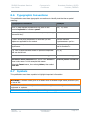
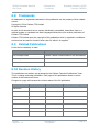

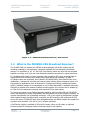
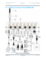

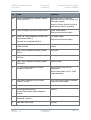
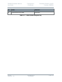
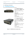
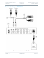
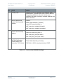
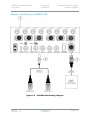

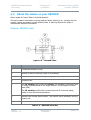
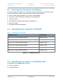
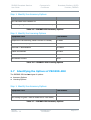
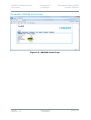
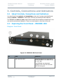
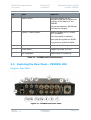
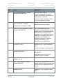

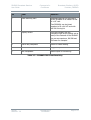
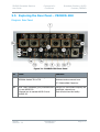
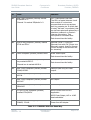


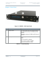
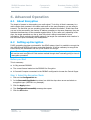
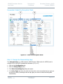
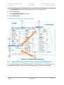
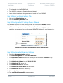

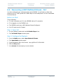

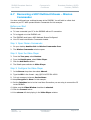
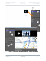

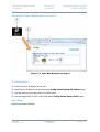
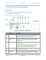


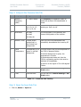
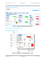
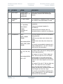

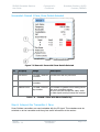
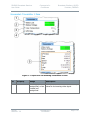

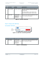
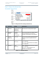
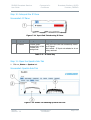
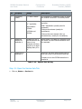
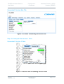
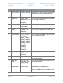
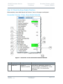


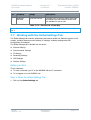


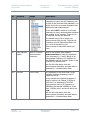
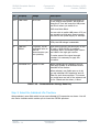
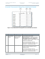
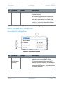

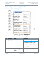
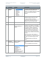
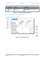
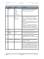


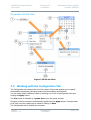

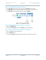
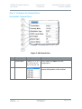

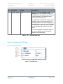
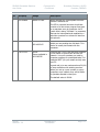

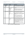
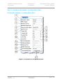
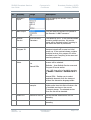
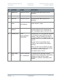
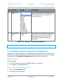

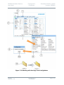

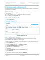


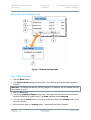


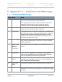
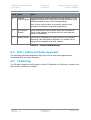

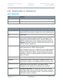

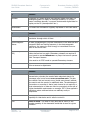
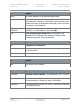
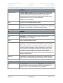

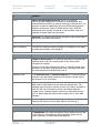
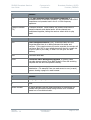
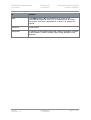
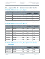

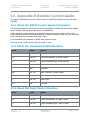
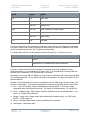

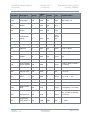


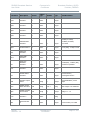

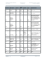
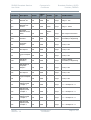
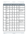
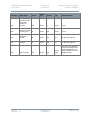

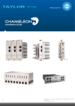


![v .] jCg _ 1l(_ `o,C..NN EinCOR `1_11E1](http://vs1.manualzilla.com/store/data/005961751_1-73960e1521729271050e00b8575619b8-150x150.png)