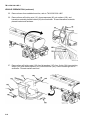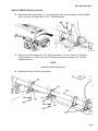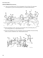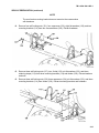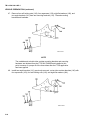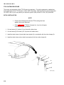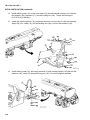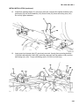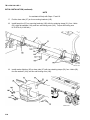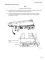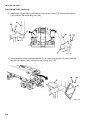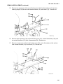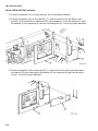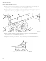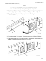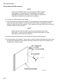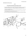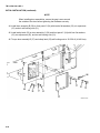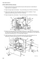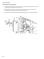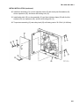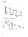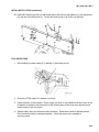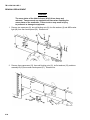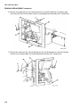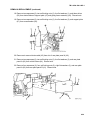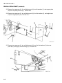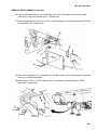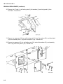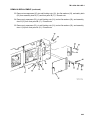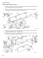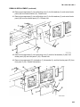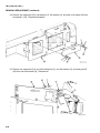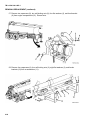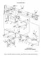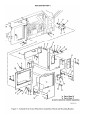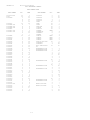
1
TB 9-2330-329-14&P-1
TECHNICAL BULLETIN
OPERATOR'S, UNIT,
INSTALLATION/REMOVAL INSTRUCTIONS, AND
REPAIR PARTS AND SPECIAL TOOLS LIST (RPSTL)
FOR
TANKER BALLISTIC PROTECTION SYSTEM (TBPS/AOA/FTSS)
FOR
SEMITRAILER, TANK, FUEL, 5000-GALLON
M967A2P1 (NSN 2330-01-538-8517)
DISTRIBUTION STATEMENT A: Approved for public release; distribution is unlimited.
HEADQUARTERS, DEPARTMENT OF THE ARMY
OCTOBER 2006
TB 9-2330-329-14&P-1
WARNING SUMMARY
For information on first aid, refer to FM 4-25.11.
WARNING
Eye and hearing protection must be worn at all times when using power tools for grinding, cutting,
sawing, and drilling. Failure to do so may result in injury to personnel.
Chemical Agent Resistant Coating (CARC) paint contains isocyanyte (HDI), which is highly irritating to
skin and respiratory system. High concentrations of HDI can produce symptoms of itching and
reddening of skin, a burning sensation in throat and nose, and watering of the eyes. In extreme
concentrations, HDI can cause cough, shortness of breath, pain during respiration, increased sputum
production, and chest tightness. The following precautions must be taken whenever using
CARC paint:
•
NEVER cut CARC-coated materials without high-efficiency, air-purifying respirators in use.
•
DO NOT grind or sand painted equipment without high-efficiency, air-purifying respirators in
use.
•
BE AWARE of CARC paint exposure symptoms; symptoms can occur a few days after initial
exposure. Seek medical help immediately if symptoms are detected.
WARNING
Use caution when lifting supplemental armor. A swinging or shifting load may cause injury
to personnel.
a
TB 9-2330-329-14&P-1
WARNING SUMMARY (continued)
WARNING
Fuel is very flammable and can explode easily. To avoid serious injury or death, keep fuel away from
open flame or any spark (ignition source). Keep a B-C fire extinguisher within reach when performing
fuel tank repair.
WARNING
Eye and hand protection must be worn at all times when applying Fuel Tanker Self-Sealing (FTSS)
Repair Kit. Failure to do so may result in injury to personnel.
WARNING
The armor plates of the Add-On-Armor (AOA) kit are heavy and awkward. Two personnel are required
at all times when installing the armor plates on the semitrailer. Failure to do so may result in injury to
personnel or damage to equipment.
b
TB 9-2330-329-14&P-1
LIST OF EFFECTIVE PAGES/WORK PACKAGES
Date of issue for original pages/work packages is:
30 October 2006
NOTE: The portion of text affected by the changes is indicated by a vertical line in the outer margins of
the page. Changes to illustrations are indicated by miniature pointing hands.
Dates of issue for original and changed pages are:
Original .. 0 .. 30 October 2006
TOTAL NUMBER OF PAGES FOR FRONT AND REAR MATTER IS 22 AND TOTAL NUMBER OF PAGES IS
154 CONSISTING OF THE FOLLOWING:
Page
Number
*Change
Number
Cover .............................................0
Warning Summary ..........................0
a and b ............................................0
A/B blank and B blank.....................0
i/ii blank and ii blank........................0
2-1 and 2-2......................................0
3-1 thru 3-46 ...................................0
4-1 thru 4-56 ...................................0
5-1 and 5-2......................................0
6-1 and 6-2......................................0
7-1 thru 7-11 blank..........................0
Figure 1 thru Back-2 blank..............0
*Zero in this column indicates an original page or work package.
A/B blank
TB 9-2330-329-14&P-1
M967A2P1 ROADSIDE
M967A2P1 CURBSIDE
TB 9-2330-329-14&P-1
HEADQUARTERS
DEPARTMENT OF THE ARMY
WASHINGTON, D.C.
30 October 2006
TECHNICAL BULLETIN
OPERATOR'S, UNIT,
INSTALLATION/REMOVAL INSTRUCTIONS, AND
REPAIR PARTS AND SPECIAL TOOLS LIST (RPSTL)
FOR
TANKER BALLISTIC PROTECTION SYSTEM (TBPS/AOA/FTSS)
FOR
SEMITRAILER, TANK, FUEL, 5000-GALLON
M967A2P1 (NSN 2330-01-538-8517)
REPORTING ERRORS AND RECOMMENDING IMPROVEMENTS
You can help improve this publication. If you find any mistakes or if you know of a way to improve
the procedures, please let us know. Submit your DA Form 2028 (Recommended Changes to
Publications and Blank Forms) through the Internet, on the Army Electronic Product Support (AEPS)
website. The Internet address is http://aeps.ria.army.mil. If you need a password, scroll down and
click on and ACCESS REQUEST FORM. The DA Form 2028 is located under the Public Application
section in the AEOPS Public Home Page. Fill out the form and click on SUBMIT. Using this form on
the AEPS will enable us to respond quicker to your comments and better manage the DA Form 2028
program. You may also mail, fax, or e-mail your letter or DA Form 2028 directly to: AMSTA-LCLPIT/TECH PUBS, TACOM-R1, 1 Rock Island Arsenal, Rock Island, IL 61299-7630. The
e-mail address is [email protected]. The fax number is DSN 793-0726 or Commercial
(309) 782-0726. A reply will be furnished to you.
DISTRIBUTION STATEMENT A: Approved for public release; distribution is unlimited.
TABLE OF CONTENTS
Page Number
CHAPTER 1 – GENERAL INFORMATION, EQUIPMENT DESCRIPTION AND DATA ....................1-1
CHAPTER 2 – PRECONDITIONS......................................................................................................2-1
CHAPTER 3 – FUEL TANK SELF-SEALING (FTSS) SYSTEM MAINTENANCE..............................3-1
CHAPTER 4 – ADD-ON-ARMOR (AOA) KIT MAINTENANCE ..........................................................4-1
CHAPTER 5 – FUEL TANK SELF-SEALING (FTSS) REPAIR KIT....................................................5-1
CHAPTER 6 – QUALITY ASSURANCE AND FINAL INSPECTION ..................................................6-1
CHAPTER 7 – SUPPORT DATA........................................................................................................7-1
i/ii blank
TB 9-2330-329-14&P-1
CHAPTER 1
GENERAL MAINTENANCE PROCEDURES
SCOPE
The purpose of this Technical Bulletin (TB) is to provide the instructions for applying the Tanker Ballistic
Protection System (TBPS) on M967A2P1 series, 5000-gallon, fuel tankers. The TBPS consists of the
Fuel Tank Self-Sealing (FTSS) System, Add-On-Armor (AOA) Kit, and FTSS Repair Kit, which all work
in conjunction to provide the fuel tanker with ballistic protection against small arms fire.
The TBPS kit is applicable to the following:
Nomenclature
M967A2
National Stock Number
2330-01-495-0040
Part Number
M779-1504-044
When completed, the vehicle NSN and part number will change for the end items as follows:
Nomenclature
M967A2P1
National Stock Number
2330-01-538-8517
Part Number
12500868-1
ARMY KNOWLEDGE ONLINE (AKO) WEBSITE
Refer to the AKO website at https://www.us.army.mil/suite/login/welcome.html for the most recent
updates to the kits and TB installation instructions.
MAINTENANCE FORMS, RECORDS, AND REPORTS
Department of the Army forms and procedures used for equipment maintenance will be those
prescribed by DA PAM 750-8, The Army Maintenance Management System (TAMMS) User’s Manual.
REPORTING EQUIPMENT IMPROVEMENT RECOMMENDATIONS (EIRs)
If your armor kit needs improvement, let us know. Send us an EIR. You, the user, are the only one who
can tell us what you don’t like about your equipment. Let us know why you don’t like the design or
performance. If you have Internet access, the easiest and fastest way to report problems or
suggestions is to go to https://aeps.ria.army.mil/aepspublic.cfm (scroll down and choose the “Submit
Quality Deficiency Report” bar). The Internet form lets you choose to submit an Equipment
Improvement Recommendation (EIR), or a Product Quality Deficiency Report (PQDR). You may also
submit your information using an SF Form 368 (Product Quality Deficiency Report). You can send your
SF Form 368 via e-mail, regular mail, or facsimile using the addresses/facsimile numbers specified in
DA PAM 750-8, The Army Maintenance Management System (TAMMS) User’s Manual. We will send
you a reply.
1-1
TB 9-2330-329-14&P-1
CORROSION PREVENTION AND CONTROL (CPC)
1. CPC of Army materiel is a continuing concern. Any corrosion problems with this item should be
reported so that they can be corrected and improvements made to prevent the problem in future
items.
2. While corrosion is typically associated with rusting of metals, it can also include deterioration of
other materials, such as rubber and plastic. Unusual cracking, softening, swelling, or breaking of
these materials may be a corrosion problem.
3. If a corrosion problem is identified, it can be reported using SF 368, Product Quality Deficiency
Report. Use of key words such as "corrosion," "rust," "deterioration," or "cracking" will ensure
that the information is identified as a CPC problem.
4. The form should be submitted to the address specified in DA PAM 750-8, The Army
Maintenance Management System (TAMMS) User’s Manual.
DESTRUCTION OF ARMY MATERIEL TO PREVENT ENEMY USE
Refer to TM 750-244-6, Procedures for Destruction of Tank-Automotive Equipment to Prevent Enemy
Use, for procedures on destruction of military vehicles.
PREPARATION FOR STORAGE OR SHIPMENT
Refer to TM 38-470, Storage and Maintenance of Army Prepositioned Stock Material, for preservation,
packaging, marking, and preparation for storage or shipment of the M967A2P1 series fuel tanker.
LIST OF ABBREVIATIONS AND ACRONYMS
AKO
AOA
AVIM
AVUM
CPC
DA PAM
DOT
EIR
FRP
FTSS
kPa
psi
TAMMS
TB
TBPS
TM
1-2
Army Knowledge Online
Add-On-Armor
Aviation Intermediate Maintenance
Aviation Unit Maintenance
Corrosion Prevention and Control
Department of the Army Pamphlet
Department of Transportation
Equipment Improvement Recommendations
Field Repair Patch
Fuel Tank Self-Sealing
Kilopascal
Pounds per Square Inch
The Army Maintenance Management System
Technical Bulletin
Tanker Ballistic Protection System
Technical Manual
TB 9-2330-329-14&P-1
CHAPTER 2
PRECONDITIONS
ADD-ON-ARMOR (AOA) AND FUEL TANKER SELF-SEALING (FTSS) VEHICLE PREPARATION
NOTE
The fuel tanker does not require purging or sniff testing prior to modification.
1. Ensure the fuel tanker has been emptied in accordance with Operator’s Manual,
TM 9-2330-329-14&P.
2. Ensure the fuel tanker is properly grounded and all vessel openings have been properly
and completely secured.
WARNING
Eye and hearing protection must be worn at all times when using power
tools for grinding, cutting, sawing, and drilling. Failure to do so may result
in injury to personnel.
Chemical Agent Resistant Coating (CARC) paint contains isocyanyte (HDI),
which is highly irritating to skin and respiratory system. High
concentrations of HDI can produce symptoms of itching and reddening of
skin, a burning sensation in throat and nose, and watering of the eyes. In
extreme concentrations, HDI can cause cough, shortness of breath, pain
during respiration, increased sputum production, and chest tightness. The
following precautions must be taken whenever using CARC paint:
•
NEVER cut CARC-coated materials without high-efficiency, air-purifying
respirators in use.
•
DO NOT grind or sand painted equipment without high-efficiency, airpurifying respirators in use.
•
BE AWARE of CARC paint exposure symptoms; symptoms can occur a
few days after initial exposure. Seek medical help immediately if
symptoms are detected.
3. Check assembly areas for any items that could interfere with the installation of the AOA and
FTSS kits. Should any items be in the way, cut or hand grind to remove those items.
4. Finish all exposed metal areas using a rust inhibitor primer and paint as specified in Table 8-4,
Materials and Parts.
5. Allow for the appropriate time for prime and paint to cure.
6. For specific vehicle preparation and application of the FTSS System and removal instructions
for unique items, refer to Chapter 3 of this TB.
2-1
TB 9-2330-329-14&P-1
AOA AND FTSS VEHICLE PREPARATION (continued)
WARNING
The armor plates of the Add-On-Armor (AOA) kit are heavy and awkward.
Two personnel are required at all times when installing the armor plates on
the semitrailer. Failure to do so may result in injury to personnel or
damage to equipment.
7. For specific installation and removal instructions of the AOA kit, refer to Chapter 4 of this TB.
2-2
TB 9-2330-329-14&P-1
CHAPTER 3
FUEL TANK SELF-SEALING (FTSS) SYSTEM
SCOPE
This section provides the instructions for applying the FTSS System to M967A2P1 series fuel tankers.
The FTSS System is a coating applied to the exterior surface of the fuel tank vessel that will seal a leak
caused by small arms fire within twenty minutes of impact. Once sealed, the fuel tanker may continue
operating under normal conditions. In the event the FTSS System does not seal a leak within twenty
minutes, a repair kit is provided to patch the affected area. Refer to Chapter 5, FTSS Repair Kit, for
instructions on applying the field patch assemblies.
ARMY KNOWLEDGE ONLINE (AKO) WEBSITE
Refer to the AKO website at https://www.us.army.mil/suite/login/welcome.html for the most recent
updates to the kits and Technical Bulletin (TB) installation instructions.
KIT PARTS AND THEIR DISPOSITION
NOTE
The items listed in Table 3-1 are FTSS kit installed parts only.
Table 3-1. FTSS Kit Contents List – 57K4865
Item
No.
Nomenclature
1
HOSE, RUBBER EPDM (5 IN.)
2
CLAMP, TUBE 1/2-2.50
3
National Stock
Number
Part Number
CAGE
Qty
5304K46
39428
2
5416K21
3A054
6
NIPPLE, DRAIN HOSE
12501996
31902
2
4
HOSE, RUBBER EPDM (42 IN.)
5304K46
39428
2
5
CLIP, UNIVERSAL CONDUIT
12500884-004
31902
4
6
SCREW, THREAD FORMING
12500885
31902
12
8
SUPPORT, PLACARD, FRONT
12502015
31902
1
9
SCREW, CAP, HEXAGON, HEAD
3/8-16X1.00
B1821BH038C100N
80204
12
10
CLIP, UNIVERSAL CONDUIT
12500884-002
31902
3
11
CLIP, UNIVERSAL CONDUIT
12500884-003
31902
5
17
SCREW, CAP, HEXAGON, HEAD
3/8-16X1.50
B1821BH038C150N
80204
4
31
PANEL, SIDE, ROADSIDE
12501994
31902
1
32
WASHER, LOCK, 3/8
MS35338-141
96906
8
34
BRACKET, RIGHT LIGHT
12502031
31902
1
143
SCREW, CAP, HEXAGON, HEAD
3/8-16X1.00
5305-00-068-0511
B1821BH038C125N
80204
25
144
WASHER, FLAT
5310-00-773-7618
MS15795-814
80205
86
4730-01-375-8073
5305-00-068-0510
5305-00-725-2317
5310-00-984-7042
3-1
TB 9-2330-329-14&P-1
KIT PARTS AND THEIR DISPOSITION (continued)
Table 3-1. FTSS Kit Contents List – 57K4865 (continued)
Item
No.
Nomenclature
National Stock
Number
Part Number
CAGE
Qty
145
BRACKET, TUBE CANISTER,
ROADSIDE
12502004
31902
4
146
NUT, SELF-LOCKING
M45913/4-6CG8Z
96906
45
147
NUT, SELF-LOCKING
M45913/4-8CG8Z
96906
17
148
WASHER, FLAT
5310-00-767-9425
MS15795-818
80205
34
149
SCREW, CAP, HEXAGON, HEAD
1/2-16X1.75
5310-01-310-2353
B1821BH050C175N
80204
17
151
BRACKET, TUBE CANISTER,
CURBSIDE
12502003
31902
4
VEHICLE PREPARATION
The following procedure removes components to allow access to restricted areas of the fuel tanker
before the FTSS System coating is applied. Once the coating has been applied, dried, and inspected,
some of the components may be reinstalled.
NOTE
Check assembly areas for any items that could interfere with the installation
of the FTSS kit, should any items be in the way, use a Hand Grinder to
remove those items. Finish all exposed metal areas using a rust inhibitor
primer and paint as specified in Table 7-4, Materials and Parts. Allow for
the appropriate time for prime and paint to cure.
3-2
1.
Ensure the semitrailer is properly grounded, refer to TM 9-2330-329-14&P.
2.
Remove two self-locking nuts (4), four flat washers (3), two capscrews (1), and hazardous
materials placard bracket (2) as a unit from front of semitrailer. Discard hardware.
TB 9-2330-329-14&P-1
VEHICLE PREPARATION (continued)
3.
Bend three clips (6) open and remove electrical conduit (5) from clips (6).
4.
Remove three clips (6) by grinding them smooth to surface of semitrailer.
5.
Bend six clips (7) open and remove two drain hose tubes (9) from clips (7).
6.
Remove six clips (7) by grinding them smooth to surface of semitrailer.
7.
Cut two drain hose tubes (8) approximately 4 to 5 inches (10 to 13 cm) from tanker body.
Ensure all sharp edges and burrs are removed. Discard drain tubes.
3-3
TB 9-2330-329-14&P-1
VEHICLE PREPARATION (continued)
8.
Remove two hoses from curbside hose tubes, refer to TM 9-2330-329-14&P. Set hoses aside
for reinstallation.
9.
Remove self-locking nut (10), two washers (11), capscrew (14), and retaining strap (13) from
mounting bracket (12). Discard hardware.
10. Remove four self-locking nuts (17), four flat washers (16), four J-bolts (18), two retaining
straps (20), and side marker light box (15) from hose tube (19). Discard washers and nuts.
NOTE
An assistant will help with Step 11.
11. Remove three self-locking nuts (24), six washers (22), three capscrews (21), three retaining
straps (25), and two curbside hose tubes (19), from three mounting brackets (23).
Discard hardware.
3-4
TB 9-2330-329-14&P-1
VEHICLE PREPARATION (continued)
12. Remove self-locking nut (28), capscrew (26), two flat washers (29), and retaining strap (13)
from mounting bracket (12) and engine compartment (27). Discard hardware.
13. Remove remaining two self-locking nuts (28), two capscrews (26), four flat washers (29), and
mounting bracket (12) from engine compartment (27). Discard mounting bracket
and hardware.
14. Remove three self-locking nuts (39), three capscrews (36), six flat washers (37), and three
retaining straps (25) from three mounting brackets (23) and fender (38). Discard hardware.
15. Remove four self-locking nuts (35), four capscrews (30), eight flat washers (31), and two
mounting brackets (23) from crossmember (34). Discard hardware.
16. Remove four self-locking nuts (40), four capscrews (33), eight flat washers (32), and two
mounting brackets (23) from fender (38). Discard hardware and mounting brackets.
3-5
TB 9-2330-329-14&P-1
VEHICLE PREPARATION (continued)
17. Remove self-locking nut (45), capscrew (43), two flat washers (44), and retaining strap (25)
from mounting bracket (23). Discard hardware.
NOTE
The rear mounting bracket does not mount to crossmember.
18. Remove two self-locking nuts (46), two capscrews (42), four flat washers (41), and mounting
bracket (23) from fender (38). Discard hardware and mounting bracket.
3-6
19.
Remove spare tire from semitrailer, refer to TM 9-2330-329-14&P.
20.
Remove two self-locking nuts (50), two washers (49), U-bolt (48), and hazardous materials
placard bracket (51) from vapor recovery pipe (47) at rear of semitrailer. Discard washers
and nuts.
TB 9-2330-329-14&P-1
VEHICLE PREPARATION (continued)
21. Remove two self-locking nuts (56), two washers (55), U-bolt (52), and winch bracket (54) from
pipe (53). Discard washers and nuts.
22. Remove four self-locking nuts (57), four washers (58), and two U-bolts (59) from pipes (47)
and (53) and brackets (60). Discard washers and nuts.
3-7
TB 9-2330-329-14&P-1
VEHICLE PREPARATION (continued)
23. Remove two nuts (65), two bolts (63), seal (62), split-pipe coupling (64), and pipe (53) from
cross assembly (66).
24. Remove two nuts (67), two bolts (60), seal (61), split-pipe coupling (68), and cross
assembly (66), with pipe (47) attached, from semitrailer.
25. Remove retaining pin (74) and ground rod (72) from ground rod storage tube (73).
NOTE
Vent tube brackets may be attached to fenders using three or four capscrews.
26. Remove six capscrews (69), six self-locking nuts (71), twelve flat washers (70), and two
brackets (60) from semitrailer. Discard hardware.
3-8
TB 9-2330-329-14&P-1
VEHICLE PREPARATION (continued)
27. Remove two self-locking nuts (76), two capscrews (78), four flat washers (77), and ladder (75)
from semitrailer. Discard washers and nuts.
28. Release two retaining pins (79), two capscrews (83), two self-locking nuts (82), four flat
washers (81), and remove two handrails (80) from platform support (84). Discard washers
and nuts.
3-9
TB 9-2330-329-14&P-1
VEHICLE PREPARATION (continued)
29. Remove two capscrews (86), two self-locking nuts (89), and four flat washers (87) from left
and right channels (88) at top of spare tire support and roadside drain pipe (85). Discard
washers and nuts.
30. Remove two capscrews (90), two self-locking nuts (93), and four flat washers (91) from
bottom support bracket (92) and spare tire support and roadside drain pipe (85). Discard
washers and nuts.
31. Remove spare tire support and roadside drain pipe (85) from semitrailer.
3-10
TB 9-2330-329-14&P-1
VEHICLE PREPARATION (continued)
32. Bend six clips (95) open and remove electrical conduit (94) from clips (95).
33. Remove six clips (95) by grinding flush to surface of semitrailer.
34. Using nut splitter (Table 7-1), remove four huck bolts (97) and vehicle identification plate panel
(96) from semitrailer. Discard huck bolts.
3-11
TB 9-2330-329-14&P-1
VEHICLE PREPARATION (continued)
35. Remove hoses from roadside hose tube, refer to TM 9-2330-329-14&P.
36. Remove three self-locking nuts (101), three capscrews (99), six washers (100), and
hazardous materials placard bracket (98) from semitrailer. Discard hazardous materials
placard bracket and hardware.
37. Remove four self-locking nuts (106), four flat washers (107), four J-bolts (104), two retaining
straps (105), and marker light box (102) from hose tube (103). Secure marker light box to
semitrailer. Discard washers and nuts.
3-12
TB 9-2330-329-14&P-1
VEHICLE PREPARATION (continued)
38. Remove two self-locking nuts (111), two capscrews (108), four flat washers (109), and ABS
light (110) from mounting bracket (112). Discard hardware.
39. Remove four self-locking nuts (115), eight flat washers (116), four J-bolts (117), and four
retaining straps (113) from hose tube (103) and four mounting brackets (114). Discard
washers and nuts.
NOTE
Assistant will help with step 40.
40. Remove hose tube (103) from semitrailer.
3-13
TB 9-2330-329-14&P-1
VEHICLE PREPARATION (continued)
41. Remove four self-locking nuts (120), four flat washers (119), two U-bolts (118), and ground
rod storage tube (73) from two mounting brackets (114). Discard washers and nuts.
42. Remove self-locking nut (127), J-bolt (125), two flat washers (126), and retaining strap (113)
from mounting bracket (114). Discard washers and nut.
43. Remove two self-locking nuts (121), two capscrews (124), four flat washers (122), and mounting
bracket (114) from crossmember (123). Discard washers and nuts.
3-14
TB 9-2330-329-14&P-1
VEHICLE PREPARATION (continued)
NOTE
The rear fender mounting bracket does not mount to the crossmember
with hardware.
44. Remove four self-locking nuts (131), four capscrews (130), eight flat washers (129), and two
mounting brackets (114) from two crossmembers (128). Discard hardware.
45. Remove three self-locking nuts (137), two J-bolts (132), six flat washers (133), and three
retaining straps (113) from three mounting brackets (114) and fender (138). Discard washers
and nuts.
46. Remove three self-locking nuts (136), three capscrews (134), six flat washers (135), and three
mounting brackets (114) from fender (138). Discard mounting brackets and hardware.
3-15
TB 9-2330-329-14&P-1
VEHICLE PREPARATION (continued)
47. Remove four self-locking nuts (142), four capscrews (139), eight flat washers (140), and
two angle brackets (141) from two mounting brackets (114). Discard mounting
brackets and hardware.
NOTE
The roadside and curbside tube canister mounting brackets and mounting
hardware are obtained from the FTSS Kit 57K4865 and installed at this
point to ensure of a proper fit of the hose tubes after the FTSS application
has been applied.
48. Install two angle brackets (141), previously removed, on two tube canister brackets (145) with
four capscrews (143), four self-locking nuts (146), and eight flat washers (144).
3-16
TB 9-2330-329-14&P-1
VEHICLE PREPARATION (continued)
49. Install two tube canister brackets (145) on crossmember (128) with six capscrews (149), six
self-locking nuts (147), and twelve flat washers (148). Do not tighten hardware.
50. Install two tube canister brackets (145) on fender (138) with eight flat washers (144), four
capscrews (143), and four self-locking nuts (146). Torque self-locking nuts
to 30-35 lb-ft (41-48 N•m).
51. Torque self-locking nuts (147) to 55-65 lb-ft (75-88 N•m).
NOTE
The rear fender tube canister bracket does not mount to a crossmemeber.
52. Position rear tube canister bracket (145) on fender (138), ensure tube canister bracket (145)
captures ABS marker light cable (150) through slot, and install with four flat washers (144),
two capscrews (143), and two self-locking nuts (146). Torque self-locking nuts
to 30-35 lb-ft (41-48 N•m).
3-17
TB 9-2330-329-14&P-1
VEHICLE PREPARATION (continued)
53. Install front tube canister bracket (145) on crossmember (128) with four flat washers (148),
two capscrews (149), and two self-locking nuts (147). Torque self-locking nuts
to 55-65 lb-ft (75-88 N•m).
54. Install tube canister bracket (151) on engine compartment (27) with four flat washers (144),
two capscrews (143), and two self-locking nuts (146). Torque self-locking nuts
to 30-35 lb-ft (41-48 N•m).
3-18
TB 9-2330-329-14&P-1
VEHICLE PREPARATION (continued)
55. Position two tube canister brackets (151) on crossmembers (34) and fender (38). Align holes
of two tube canister brackets (151) with existing holes of crossmembers (34) and install with
sixteen flat washers (148), eight capscrews (149), and eight self-locking nuts (147). Do not
fully tighten hardware.
56. Install two tube canister brackets (151) on fender (38) with twelve flat washers (144),
six capscrews (143), and six self-locking nuts (146). Torque self-locking nuts
to 30-35 lb-ft (41-48 N•m).
57. Torque self-locking nuts (147) to 55-65 lb-ft (75-88 N•m).
NOTE
The rear fender tube canister bracket does not mount to a crossmember.
58. Install rear tube canister bracket (151) on fender (38) with four flat washers (144),
two capscrews (143), and two self-locking nuts (146). Torque self-locking nuts
to 30-35 lb-ft (41-48 N•m).
NOTE
Vehicle preparation has been completed. Forward the semittrailer to the
appropriate facility for FTSS application.
3-19
TB 9-2330-329-14&P-1
FTSS SYSTEM PROCEDURE
The source and application of the FTSS System is proprietary. For vehicle preparation, applications,
and reapplication of the FTSS System, contact VSE Corporation, 2550 Huntington Avenue, Alexandria,
VA 22303-1499. Or you may submit your request by phone (800) 455-4873 or fax (703) 960-2688.
INITIAL INSTALLATION
NOTE
•
Perform the following task after the FTSS coating has been
applied, dried, and inspected.
•
Refer to Table 3-1, FTSS Kit Contents List, for a list of all parts
installed during this procedure.
1. Cut two hoses (1) 5 inches (13 cm) from bulk rubber hose.
2. Cut two hoses (4) 42 inches (107 cm) from bulk rubber hose.
3. Install two drain hoses (1) and drain hose nipples (3) on semitrailer with four tube clamps (2).
4. Install two drain hoses (4) on drain hose nipples (3) with two tube clamps (2).
3-20
TB 9-2330-329-14&P-1
INITIAL INSTALLATION (continued)
5. Install two drain hoses (4) on semitrailer with four universal conduit clips (5) and four thread
forming screws (6).
6. Install front placard support (8), previously removed, on front of semitrailer with four flat
washers (144), two capscrews (9), and two self-locking nuts (146). Torque self-locking nuts
to 30-35 lb-ft (41-48 N•m).
7. Install hazardous materials placard bracket (7) on front placard support (8) with four flat
washers (144), two capscrews (9), and two self-locking nuts (146). Torque self-locking nuts
to 30-35 lb-ft (41-48 N•m).
3-21
TB 9-2330-329-14&P-1
INITIAL INSTALLATION (continued)
8. Install electrical conduit (11) on semitrailer with three universal conduit clips (10) and three
thread forming screws (6).
9. Install retaining strap (12), previously removed, on tube canister bracket (151) and engine
compartment (13) with two flat washers (144), capscrew (143), and self-locking nut (146).
Torque self-locking nut to 30-35 lb-ft (41-48 N•m).
3-22
TB 9-2330-329-14&P-1
INITIAL INSTALLATION (continued)
10.
Install two retaining straps (14), previously removed, on two tube canister brackets (151) and
fender (15) with two flat washers (144), capscrew (143), and self-locking nut (146). Torque
self-locking nut to 30-35 lb-ft (41-48 N•m).
NOTE
An assistant will help with Steps 11 and 12.
11.
Install two hose tubes (16) on tube canister brackets (151) and secure in place with three
retaining straps (14), six flat washers (144), three capscrews (17), and three self-locking
nuts (146). Torque self-locking nuts to 30-35 lb-ft (41-48 N•m).
3-23
TB 9-2330-329-14&P-1
INITIAL INSTALLATION (continued)
12.
Install retaining strap (12) on two hose tubes (16) and tube canister bracket (151) with two
flat washers (144), capscrew (17), and self-locking nut (146). Torque self-locking nut
to 30-35 lb-ft (41-48 N•m).
13.
Install side marker light box (18), previously removed, on hose tube (16) with two retaining
straps (20), four J-bolts (19), four self-locking nuts (146), and four flat washers (144).
14.
Install retaining strap (21), previously removed, on tube canister bracket (145) with two flat
washers (144), J-bolt (22), and self-locking nut (146). Do not fully tighten hardware.
3-24
TB 9-2330-329-14&P-1
INITIAL INSTALLATION (continued)
15.
Install three retaining straps (21), previously removed, on three tube canister brackets (145)
and fender (23) with six flat washers (144), three J-bolts (22), three self-locking nuts (146).
Do not fully tighten hardware.
16.
Insert ground rod storage tube (25), previously removed, through three mounting brackets
(145) and install with two U-bolts (24), previously removed, four flat washers (144), and four
self-locking nuts (146). Torque self-locking nuts to 30-35 lb-ft (41-48 N•m).
3-25
TB 9-2330-329-14&P-1
INITIAL INSTALLATION (continued)
NOTE
An assistant will help with Steps 17 and 18.
17.
Position hose tube (27) on four mounting brackets (145).
18.
Install hose tube (27) on mounting brackets (145) with four retaining straps (21), four J-bolts
(26), eight flat washers (144), and four self-locking nuts (146). Torque self-locking nuts
to 30-35 lb-ft (41-48 N•m).
19.
Install marker light box (28) on hose tube (27) with two retaining straps (30), four J-bolts (29),
four flat washers (144), and four self-locking nuts (146).
3-26
TB 9-2330-329-14&P-1
INITIAL INSTALLATION (continued)
NOTE
An assistant will help with Step 20.
20.
Install side panel (31) on semitrailer with four capscrews (9), four lockwashers (32), and four
flat washers (144). Torque capscrews to 30-35 lb-ft (41-48 N•m).
21.
Install vehicle identification panel (33), previously removed, on side panel (31) with four
capscrews (9), four lockwashers (32), and four flat washers (144). Torque capscrews
to 30-35 lb-ft (41-48 N•m).
3-27
TB 9-2330-329-14&P-1
INITIAL INSTALLATION (continued)
22.
Install rear light bracket (34) on rear tube canister bracket (145) with two capscrews (143),
four flat washers (144), and two self-locking nuts (146). Torque self-locking nuts
to 30-35 lb-ft (41-48 N•m).
23.
Install ABS marker light (35) on rear light bracket (34) with two capscrews (143), four flat
washers (144), and two self-locking nuts (146). Torque self-locking nuts
to 30-35 lb-ft (41-48 N•m).
24.
Install electrical conduit (36) on semitrailer with five universal conduit clips (37) and five thread
forming screws (6).
3-28
TB 9-2330-329-14&P-1
FOLLOW-ON TASK
1. Position spare tire support and roadside drain pipe (1) on the semitrailer. Install spare tire
support and roadside drain pipe (1) on bottom support bracket (3) with four new flat
washers (144), two capscrews (2), and two new self-locking nuts (146). Torque self-locking
nuts to 30-35 lb-ft (41-48 N•m).
2. Install spare tire support and roadside drain pipe (1) on left and right channels (5) four new flat
washers (144), two capscrews (4), and two new self-locking nuts (146). Torque self-locking
nuts to 30-35 lb-ft (41-48 N•m).
3-29
TB 9-2330-329-14&P-1
FOLLOW-ON TASK (continued)
3. Position two handrails (7) on platform support (9) and secure using two retaining pins (6), four
new flat washers (144), two capscrews (8), and two new self-locking nuts (146). Torque selflocking nuts to 30-35 lb-ft (41-48 N•m).
4. Install ladder (10) on semitrailer with four new flat washers (144), two capscrews (11), and two
new self-locking nuts (146). Do not fully tighten hardware.
3-30
TB 9-2330-329-14&P-1
FOLLOW-ON TASK (continued)
NOTE
Vent tube brackets may be attached to fender using three or four capscrews.
5. Install two brackets (12) on semitrailer with sixteen flat washers (144), eight capscrews (143),
and eight new self-locking nuts (146). Torque self-locking nuts to 30-35 lb-ft (41-48 N•m).
6. Insert ground rod (13) into ground rod storage tube (14) and secure with retaining pin (15).
7. Install cross assembly (24), with pipe (23) attached, on semitrailer with seal (17), split-pipe
coupling (26), two capscrews (16) and two nuts (25).
8. Install pipe (20) on cross assembly (24) with seal (18), split-pipe coupling (21), two capscrews
(19), and two nuts (22).
3-31
TB 9-2330-329-14&P-1
FOLLOW-ON TASK (continued)
9. Install pipes (20) and (23) on two brackets (12) with two U-bolts (27), four new flat washers
(144), and four new self-locking nuts (146).
10. Install hazardous materials placard bracket (51) on vapor recovery pipe (47) with U-bolt (48),
two new flat washers (144), and two new self-locking nuts (146).
3-32
TB 9-2330-329-14&P-1
REMOVAL/REPLACEMENT
1.
Remove six thread forming screws (6), six universal conduit clips (37), and conduit (36) from
semitrailer.
2.
Remove four capscrews (9), four flat washers (144), four lockwashers (32), and identification
plate (33) from side panel (31). Discard lockwashers.
3.
Remove four capscrews (9), four flat washers (144), four lockwashers (32), and side panel
(31) from semitrailer. Discard lockwashers.
3-33
TB 9-2330-329-14&P-1
REMOVAL/REPLACEMENT (continued)
4.
Remove four self-locking nuts (146), four washers (144), four J-bolts (29), two retaining
straps (30), and marker light box (28) from hose tube (27). Discard nuts.
5.
Remove two capscrews (143), two self-locking nuts (146), four flat washers (144), and ABS
marker light (35) from rear light bracket (34). Discard nuts.
6.
Remove two capscrews (143), two self-locking nuts (146), four flat washers (144), and rear
light bracket (34) from tube canister bracket (145). Discard nuts.
3-34
TB 9-2330-329-14&P-1
REMOVAL/REPLACEMENT (continued)
7.
Remove four self-locking nuts (146), eight flat washers (144), four J-bolts (26), and four
retaining straps (21), from hose tube (27) and four tube canister brackets (145). Discard nuts.
NOTE
An assistant will help with Step 8.
8.
Remove hose tube (27) from semitrailer.
3-35
TB 9-2330-329-14&P-1
REMOVAL/REPLACEMENT (continued)
9.
Remove retaining pin (31) and ground rod (32) from ground rod storage tube (33).
10. Remove six self-locking nuts (146), six flat washers (144), and two U-bolts (24) from two tube
canister brackets (145) and ground rod storage tube (25). Discard nuts.
11. Remove ground rod storage tube (25) from three tube canister brackets (145).
3-36
TB 9-2330-329-14&P-1
REMOVAL/REPLACEMENT (continued)
NOTE
The rear fender tube canister bracket does not mount to a crossmember.
12. Remove two self-locking nuts (146), two flat washers (144), two J-bolts (22), and retaining
strap (21), from tube canister bracket (145) and fender (23). Discard nuts.
13. Remove two capscrews (143), two self-locking nuts (146), four flat washers (144) and tube
canister bracket (145) from fender (23). Discard nuts.
14. Remove two self-locking nuts (146), four flat washers (144), two J-bolts (22), and retaining
straps (21), from two tube canister brackets (145) and fender (23). Discard nuts.
3-37
TB 9-2330-329-14&P-1
REMOVAL/REPLACEMENT (continued)
15. Remove six capscrews (149), six self-locking nuts (147), twelve flat washers (148), and two
fender tube canister brackets (145) from two crossmembers (128). Discard nuts.
16. Remove two capscrews (143), two self-locking nuts (146), four flat washers (144) and two
fender tube canister brackets (145) from fender (23). Discard nuts.
17. Remove self-locking nut (146), two flat washers (144), two J-bolts (22), and retaining
strap (21) from front tube canister bracket (145). Discard nut.
18. Remove three capscrews (149), three self-locking nuts (147), six flat washers (148), and front
tube canister bracket (145) from crossmember (128). Discard nuts.
3-38
TB 9-2330-329-14&P-1
REMOVAL/REPLACEMENT (continued)
19. Remove two capscrews (143), two self-locking nuts (146), four flat washers (144), and angle
bracket (141) from two tube canister brackets (145). Discard nuts.
20. Remove capscrew (17), self-locking nut (146), two flat washers (144), and retaining strap (12)
from tube canister brackets (151). Discard nuts.
21. Remove four self-locking nuts (146), four flat washers (144), four J-bolts (19), two retaining
straps (20), and side marker light box (18) from two hose tubes (16). Discard nuts.
3-39
TB 9-2330-329-14&P-1
REMOVAL/REPLACEMENT (continued)
NOTE
An assistant will help with Step 23.
22. Remove three capscrews (17), three self-locking nuts (146), six flat washers (144), three
retaining straps (14), and two hose tubes (16) from three tube canister brackets (151).
Discard nuts.
23. Remove capscrew (143), self-locking nut (146), two flat washers (144), and retaining strap
(12) from tube engine bracket (151) and engine compartment (13). Discard nuts.
24. Remove two capscrews (143), two self-locking nuts (146), four flat washers (144), and tube
canister bracket (151) front engine compartment (13). Discard nuts.
3-40
TB 9-2330-329-14&P-1
REMOVAL/REPLACEMENT (continued)
25. Remove two capscrews (143), two self-locking nuts (146), four flat washers (144), and two
retaining straps (14) from two tube canister brackets (151) and fender (15). Discard nuts.
26. Remove eight capscrews (149), eight self-locking nuts (147), sixteen flat washers (148), and
two canister brackets (151) from crossmembers (38). Discard nuts.
27. Remove six capscrews (143), six self-locking nuts (146), twelve flat washers (144), and two
tube canister brackets (151) from fender (15). Discard nuts.
3-41
TB 9-2330-329-14&P-1
REMOVAL/REPLACEMENT (continued)
28. Remove capscrew (143), self-locking nut (146), two flat washers (144), and retaining strap
(14) from rear tube canister bracket (151) and fender (15). Discard nuts.
29. Remove two capscrews (143), two self-locking nuts (146), four flat washers (144), and rear
tube canister bracket (151) from fender (15). Discard nut.
30. Remove six tube clamps (5), two drain hose nipples (3), two drain hoses (1), and two drain
hoses (4) from semitrailer.
3-42
TB 9-2330-329-14&P-1
REMOVAL/REPLACEMENT (continued)
31.
Remove four thread forming screws (6), four universal conduit clips (5), and two drain
hoses (4) from semitrailer.
32. Remove two capscrews (9), two self-locking nuts (146), four flat washers (144), and
hazardous materials placard bracket (7) from front placard support (8). Discard locknuts.
33. Remove two capscrews (9), two self-locking nuts (146), four flat washers (144), and front
placard support (8) from front of semitrailer. Discard nuts.
3-43
TB 9-2330-329-14&P-1
REMOVAL/REPLACEMENT (continued)
34. Remove three thread forming screws (6), and three universal conduit clips (10) from
electrical conduit (11).
3-44
TB 9-2330-329-14&P-1
CHAPTER 4
ADD-ON-ARMOR (AOA) KIT
SCOPE
This chapter provides the parts list, installation, and removal instructions for the AOA kit.
TOOLS AND SPECIAL TOOLS
For a list of tools and special tools needed to install the AOA kit, refer to Chapter 7, Table 7-2.
ARMY KNOWLEDGE ONLINE (AKO) WEBSITE
Refer to the AKO website at https://www.us.army.mil/suite/login/welcome.html for the most recent
updates to the kits and TB installation instructions.
KIT PARTS AND THEIR DISPOSITION
The following lists the kit components of the AOA kit. This list can be used to inventory the
kit for completeness.
NOTE
The items listed in Table 4-1 are AOA kit installed parts only.
Table 4-1. AOA Kit Contents List – 57K4863
Item
No.
Nomenclature
National Stock
Number
Part Number
CAGE
QTY
1
T-Bolt, Belly Panel
12502022
31902
8
2
Nut, Self-Locking, 1/2-13
M45913/4-8CG8Z
96906
107
3
Washer, Flat, 1/2
MS15795-818
96906
216
4
Panel, Belly, Roadside
12501992
31902
1
5
Panel, Belly, Curbside
12501993
31902
1
7
Washer, Lock, 1/2
MS35338-143
96906
12
8
Bracket, Front Curbside
12502013-001
31902
1
9
Screw, Cap, Hexagon, Head,
1/2-13X1.75
B1821BH050C175N
80204
97
12
Fender, Bracket Curbside
12501988
31902
2
13
Support, Plate, Curbside
12501960
31902
1
14
Brace, Angle
12502026
31902
2
15
Cover, Gap Adjustment, Curbside
12502020
31902
1
16
Plate, Rear, Curbside
12501959
31902
1
17
Panel B, Front Curbside
12501982
31902
1
18
Nut Jam, Hex 5/8-11
MS35691-49
96906
6
19
Screw, Cap
92620A811
3A054
2
20
Screw, Cap, Hexagon, Head,
1/2-13X1.25
B1821BH050C125N
80204
8
21
Panel A, Front Curbside
12501981
31902
1
5310-00-787-9425
5310-00-933-8778
5305-00-071-2070
5310-00-851-2677
5305-00-071-2067
4-1
TB 9-2330-329-14&P-1
KIT PARTS AND THEIR DISPOSITION (continued)
Table 4-1. AOA Kit Contents List – 57K4863 (continued)
Item
No.
4-2
Nomenclature
National Stock
Number
Part Number
CAGE
QTY
12501987
31902
1
B1821BH050C200N
80204
2
12501986
31902
1
B1821BH050C250N
80204
4
Panel, Tube, Cover Curbside
12502011
31902
1
27
Panel, Fender, Front Curbside
12502010
31902
1
28
Panel, Fender, Center Curbside
12502009
31902
1
29
Panel, Fender, Rear Curbside
12502008
31902
1
30
Bracket, Panel Rear Fender,
Curbside
12502025
31902
1
31
Nut, Self-Locking, 3/8-16
M45913/4-6CG8Z
96906
52
32
Washer, Flat, 3/8
5310-00-773-7618
MS15795-814
96906
104
33
Screw, Cap, Hexagon, Head,
3/8-16X1.25
5305-00-068-0511
B1821BH038C125N
80204
44
34
Door A Assembly, Curbside
12501963
31902
1
35
Latch, Safety Right
12500887-002
31902
3
36
Screw, Cap, Hexagon, Head,
3/8-16X1.50
B1821BH038C150N
80204
8
37
Door B Assembly, Curbside
12501962
31902
1
38
Door C Assembly, Curbside
12501961
31902
1
40
Panel B, Bracket Roadside
12502012
31902
1
41
Panel B, Rear, Plate Roadside
12501991
31902
1
43
Plate, Support Roadside
12501967
31902
1
46
Panel A, Rear, Plate, Roadside
12501990
31902
1
47
Support Plate, Roadside
12501969
31902
1
50
Shim
12502032
51
Door Frame, Left, Front Roadside
12502001
52
Screw, Cap
92620A806
53
Door Frame, Right, Front Roadside
12501968
31902
1
54
Spacer, Plate Adjustment
12502016
31902
2
56
Panel, Fender, Front, Roadside
12502005
31902
1
57
Panel, Fender, Center, Roadside
12502006
31902
1
58
Panel, Fender, Rear, Roadside
12502007
31902
1
59
Latch, Safety Left
12500887-001
31902
1
60
Door, Left Assembly Roadside
12502000
31902
1
61
Door, Right Assembly Roadside
12501965
31902
1
22
Panel D, Front Curbside
23
Screw, Cap, Hexagon, Head,
1/2-13X2.00
24
Panel C, Front Curbside
25
Screw, Cap
26
5305-00-071-2071
5305-00-071-2073
5305-00-725-6317
3
31902
1
4
TB 9-2330-329-14&P-1
KIT PARTS AND THEIR DISPOSITION (continued)
Table 4-1. AOA Kit Contents List – 57K4863 (continued)
Item
No.
National Stock
Number
Nomenclature
62
Door Assembly Brake Access,
Roadside
63
Screw, Cap, Hexagon Head
16X0.75
65
Nut, Self-Locking
66
Washer, Flat
1/4-
5305-00-008-0508
5310-01-304-8733
Part Number
CAGEC
QTY
12501964
31902
1
B1821BH025C075N
31902
2
M45913/4-4CG8Z
31902
2
MS15795-852
31902
4
VEHICLE PREPARATION
NOTE
Check assembly areas for any items that could interfere with the installation
of the AOA kits, should any items be in the way; use a Hand Grinder to
remove those items. Finish all exposed metal areas using a rust inhibitor
primer and paint as specified in Table 7-4, Materials and Parts. Allow for
the appropriate time for prime and paint to cure.
1. Remove eight nuts (3), eight flat washers (2), and two bolt strips (1) from semitrailer. Discard
bolt strips and hardware.
4-3
TB 9-2330-329-14&P-1
VEHICLE PREPARATION (continued)
WARNING
Engine compertment door must be secured in the open position prior
to removing from the engine compartment shroud. Failure to do so
may cause injury to personnel.
2. Open engine compartment door.
3. Remove two self-locking nuts (10), two capscrews (7), and four flat washers (8) from engine
compartment shroud (5). Discard hardware.
4. Remove rivets, as necessary, and engine compartment door (4) from engine compartment
shroud (5). Discard engine compartment door and hardware.
5. Grind two latches (9) from engine compartment shroud (5).
6. Remove nut (11) and eye bolt with chain (6) from engine compartment shroud (5). Discard eye
bolt with chain and hardware.
4-4
TB 9-2330-329-14&P-1
VEHICLE PREPARATION (continued)
7. Remove nut (14), capscrew (12), two flat washers (15), and landing leg handle bracket (16)
from pipe frame assembly (13). Discard hardware.
8. Remove two capscrews (17), two self-locking nuts (20), four flat washers (18), and ABS marker
light (19) from rear light bracket (21). Discard hardware.
9. Remove two capscrews (22), two self-locking nuts (24), four flat washers (23), and rear light
bracket (21) from tube canister bracket (25). Discard rear light bracket and hardware.
4-5
TB 9-2330-329-14&P-1
INITIAL INSTALLATION
WARNING
The armor plates of the Add-On-Armor (AOA) kit are heavy and
awkward. Two personnel are required at all times when installing the
armor plates on the semitrailer. Failure to do so may result in injury
to personnel or damage to equipment.
NOTE
Refer to Table 4-1, AOA Kit Contents List, for a list of all AOA kit components.
1. Install belly panel (4) on semitrailer with four T-bolts (1), four flat washers (3), and four selflocking nuts (2). Do not fully tighten hardware.
2. Install belly panel (5) on semitrailer with four T-bolts (1), four flat washers (3), and four selflocking nuts (2). Do not fully tighten hardware.
3. Install belly panel (5) on belly panel (4) with six capscrews (6), six lockwashers (7), and six flat
washers (3). Do not fully tighten hardware.
4. Tighten belly panel (4) and belly panel (5) hardware. Torque capscrews and self-locking nuts
to 55-65 lb-ft (75-88 N•m).
4-6
TB 9-2330-329-14&P-1
INITIAL INSTALLATION (continued)
5. Install front bracket (8) on engine shroud (10) with four flat washers (3), two capscrews (9), and
two self-locking nuts (2). Do not fully tighten hardware.
6. Install two fender brackets (12) on crossmembers (11) with eight flat washers (3), four
capscrews (9), and four self-locking nuts (2). Do not fully tighten hardware.
4-7
TB 9-2330-329-14&P-1
INITIAL INSTALLATION (continued)
7. Install gap adjustment cover (15) and angle brace (14) on support plate (13) with four flat
washers (3), two capscrews (9), and two self-locking nuts (2). Do not fully tighten hardware.
8. Position support plate (13) on crossmember. Align holes of support plate (13) with existing
holes of crossmember and install with ten flat washers (3), five capscrews (9), and five selflocking nuts (2). Do not fully tighten hardware.
4-8
TB 9-2330-329-14&P-1
INITIAL INSTALLATION (continued)
9. Position rear plate (16) on vehicle frame and support plate (13). Align holes of rear plate (16)
with existing holes of vehicle frame and install with four flat washers (3), two capscrews (9), and
two self-locking nuts (2). Do not fully tighten hardware.
10. Install rear plate (16) on support plate (13) with ten flat washers (3), five capscrews (9), and five
self-locking nuts (2). Do not fully tighten hardware.
11. Tighten all rear plate (16) and support plate (13) hardware. Do not tighten gap adjustment cover
and angle bracket hardware. Torque self-locking nuts to 55-65 lb-ft (75-88 N•m).
12. Install two capscrews (19) and two jam nuts (18) on front panel B (17). Do not
fully tighten hardware.
4-9
TB 9-2330-329-14&P-1
INITIAL INSTALLATION (continued)
13. Position front panel B (17) on engine housing. Do not fully tighten hardware.
14. Position front panel A (21) on front panel B (17). Align front panel A (21) with holes in front
panel B (17) and install with six capscrews (20), two lockwashers (7), two flat washers (3), eight
flat washers (3), four capscrews (9), and four self-locking nuts (2). Do not fully tighten hardware.
15. Position front panel D (22) on front panel B (17). Align holes of front panel D (22) with holes in
front panel B (17) and install with ten flat washers (3), five capscrews (9) and five self-locking
nuts (2). Do not fully tighten hardware.
4-10
TB 9-2330-329-14&P-1
INITIAL INSTALLATION (continued)
16. Extend front bracket (8) to meet front panel D (22) and front panel B (17) and install with four flat
washers (3), two capscrews (23), and two self-locking nuts (2).
17. Tighten all front panel D (22) and front bracket (8) hardware. Torque self-locking nuts
to 55-65 lb-ft (75-88 N•m).
18. Position front panel C (24) on front panel B (17). Align holes of front panel C (24) with holes in
front panel B (17) and install with eight flat washers (3), four capscrews (9), and four self-locking
nuts (2). Do not fully tighten hardware.
19. Install front panel D (22) on front panel C (24) with eight flat washers (3), four capscrews (9),
and four self-locking nuts (2). Do not fully tighten hardware.
20. Expand angle brace (14) to meet front panel C (24) and install with four flat washers (3), two
capscrews (9), and two self-locking nuts (2). Do not fully tighten hardware.
4-11
TB 9-2330-329-14&P-1
INITIAL INSTALLATION (continued)
21. Position tube cover panel (26) on front panel C (24). Align holes of tube cover panel (26) with
holes in front panel C (24) and install with three capscrews (25), lockwashers (7), and flat
washers (3). Do not fully tighten hardware.
22. Position front fender panel (27) on tube cover panel (26), and front panel C (24). Align holes of
front fender panel (27) with holes of tube cover panel (26), and install with two flat washers (3),
capscrew (9), and two self-locking nuts (2). Do not fully tighten hardware
23. Install front fender panel (27) on front panel C (24) with capscrew (25), lockwasher (7), and flat
washer (3). Do not fully tighten hardware.
4-12
TB 9-2330-329-14&P-1
INITIAL INSTALLATION (continued)
24. Position center fender panel (28) on front fender panel (27). Align holes of center fender panel
(28) with holes of front fender panel (27) and install with four flat washers (3), two capscrews (9),
and two self-locking nuts (2). Do not fully tighten hardware.
25. Install center fender panel (28) on fender bracket (12) with four flat washers (3), two capscrews
(9), and two self-locking nuts (2). Do not fully tighten hardware.
26. Position rear panel (29) on center fender panel (28). Align holes of rear fender panel (29) with
holes of center fender panel (28) and install with four flat washers (3), two capscrews (9), and
two self-locking nuts (2). Do not fully tighten hardware.
27. Install rear fender panel (29) on fender bracket (12) with four flat washers (3), two capscrews
(9), and two self-locking nuts (2). Do not tighten hardware.
4-13
TB 9-2330-329-14&P-1
INITIAL INSTALLATION (continued)
28. Install rear fender panel bracket (30) on rear fender panel (29) with four flat washers (3), two
capscrews (9), and two self-locking nuts (2). Do not fully tighten hardware.
29. Install rear fender panel bracket (30) on rear fender with four flat washers (32), two capscrews
(33), and two self-locking nuts (31). Do not fully tighten hardware.
30. Raise two fender brackets (12) parallel with fender. Tighten all fender bracket hardware.
Torque self-locking nuts to 55-65 lb-ft (75-88 N•m).
31. Tighten all rear fender panel hardware. Torque self-locking nuts to 55-65 lb-ft (75-88 N•m).
4-14
TB 9-2330-329-14&P-1
INITIAL INSTALLATION (continued)
NOTE
Ensure front panel B 12502024 and front panel A 12501980 are aligned
flush and even with the engine housing before tightening clamp screws.
32. Align front panel B (17) and front panel A (21) flush with bottom of engine housing. Tighten two
capscrews (19) and jam nuts (18) to secure front panel B (17) on engine housing.
33. Tighten all armor panel hardware. Torque capscrews and self-locking nuts
to 55-65 lb-ft (75-88 N•m).
34. Tighten all front panel C (24) hardware. Torque self-locking nuts to 55-65 lb-ft (75-88 N•m).
35. Extend gap adjustment cover (15) to meet front panel C (24) and tighten gap adjustment cover
hardware. Torque self-locking nuts to 55-65 lb-ft (75-88 N•m).
4-15
TB 9-2330-329-14&P-1
INITIAL INSTALLATION (continued)
NOTE
Armor door assemblies may or may not have door handles installed
when shipped. If door handles are not installed they are supplied
separately with each door assembly. Perform Steps 36 through 39 to
install the door handle on all curbside door assemblies.
36. Position one Teflon washer on door handle.
37. From the outside of the armor door assembly, insert threaded end of door handle through the
hole in the armor door assembly. Position second Teflon washer on threaded end of door
handle on inside of armor door assembly. Teflon washers must contact the exterior and interior
surfaces of the armor door assembly.
NOTE
Ensure the key in the hole seats on the key of the threaded portion of the
door handle. The latch must be positioned so that the bent ends of the latch
point away from the armor door assembly.
38. Position latch onto threaded end of door handle and install with self-locking nut.
39. Check operation of door handle. Proper range of motion of door handle limits latch travel to the
90 degree arc between the latch stops on the inside surface of the armor door assembly and
inside surface of the door frame.
4-16
TB 9-2330-329-14&P-1
INITIAL INSTALLATION (continued)
NOTE
When installing door assemblies, ensure the gap is even around
the outside of the door before tightening the hardware securely.
40. Install door assembly A (34) on front panel A (21) with twelve flat washers (32), six capscrews
(33), and six self-locking nuts (31). Torque self-locking nuts to 30-35 lb-ft (41-48 N•m).
41. Install door assembly B (37) on front panel B (17) with twelve flat washers (32), six capscrews
(33), and six self-locking nuts (31).
42. Install safety latch (35) on door assembly B (37) and front panel B (17) with four flat washers
(32), two capscrews (36), and two self-locking nuts (31).
43. Torque door assembly B (37) and safety latch (35) self-locking nuts to 30-35 lb-ft (41-48 N•m).
4-17
TB 9-2330-329-14&P-1
INITIAL INSTALLATION (continued)
NOTE
When installing door assemblies, ensure the gap is even around
the outside of the door before tightening the hardware securely.
44. Install door assembly B (38) on front panel C (24) with twelve flat washers (32), six capscrews
(33), and six self-locking nuts (31).
45. Install safety latch (35) on door assembly C (38) and front panel C (24) with four flat washers
(32), two capscrews (36), and two self-locking nuts (31).
46. Torque door assembly B (37) and safety latch (35) self-locking nuts to 30-35 lb-ft (41-48 N•m).
4-18
TB 9-2330-329-14&P-1
INITIAL INSTALLATION (continued)
47. Install panel bracket (40) on crossmember (39) with two flat washers (3), capscrew (9), and selflocking nut (2). Do not tighten hardware.
48. Install rear panel plate B (41) on panel bracket (40) with four flat washers (3), two capscrews (9),
and two self-locking nuts (2). Do not tighten hardware.
49. Install rear panel plate B (41) on piping frame housing (42) with two flat washers (3),
capscrew (9), and self-locking nut (2). Do not fully tighten hardware.
50. Clamp rear panel plate B (41) on piping frame housing (42) as shown. Using 19/32 inch drill bit
and rear panel plate B (41) as a template, drill a hole through piping frame assembly (42) at
location marked A, as shown.
4-19
TB 9-2330-329-14&P-1
INITIAL INSTALLATION (continued)
51. Install rear panel plate B (41) on piping frame assembly (42) with two flat washers (3),
capscrew (9), and self-locking nut (2).
52. Tighten rear panel plate B (41) and panel bracket (40) hardware. Torque self-locking nuts
to 55-65 lb-ft (75-88 N•m).
53. Install angle brace (14) on support plate (43) with four flat washers (3), two capscrews (9), and
two self-locking nuts (2). Do not tighten hardware.
54. Position support plate (43) on rear panel plate B (41) and install with ten flat washers (3), five
capscrews (9), and five self-locking nuts (2). Torque self-locking nuts
to 55-65 lb-ft (75-88 N•m).
4-20
TB 9-2330-329-14&P-1
INITIAL INSTALLATION (continued)
55. Position rear panel plate A (46) on rear panel plate B (41) and vehicle frame (44). Install rear
panel plate A (46) on rear panel plate B (41) with eight flat washers (3), four capscrews (9), and
four self-locking nuts (2).
56. Install rear panel plate A (46) on vehicle frame (44) with four flat washers (3), two capscrews (9),
and two self-locking nuts (2).
57. Insert air reservoir drain cable (45) through slot of rear panel plate A (46).
58. Torque rear panel plate A (46) self-locking nuts to 55-65 lb-ft (75-88 N•m).
4-21
TB 9-2330-329-14&P-1
INITIAL INSTALLATION (continued)
NOTE
Do not fully tighten capscrews or clamping screws until armor is
properly positioned and aligned on piping frame assembly.
59. Position support plate (47) on crossmember (48). Align holes of support plate (47) with existing
holes of crossmember (48) and install with four flat washers (3), two capscrews (9), and two
self-locking nuts (2). Do not fully tighten hardware.
60. Align slotted holes of support plate (47) with existing holes of piping frame assembly (49),
insert three shims (50) between support plate (47) and piping frame assembly (49), and
install with six flat washers (3), three capscrews (9), and three self-locking nuts (2). Do not
fully tighten hardware.
4-22
TB 9-2330-329-14&P-1
INITIAL INSTALLATION (continued)
61. Install two capscrews (52) and two jam nuts (18) on front left door frame (51).
62. Position front left door frame (51) on piping frame assembly (49) and support plate (47).
Do not tighten capscrews and nuts until front left door frame (51) is properly aligned on
piping frame assembly.
63. Align holes of front left door frame (51) with holes of support plate (47) and install with ten flat
washers (3), five capscrews (9), and five self-locking nuts (2). Do not fully tighten hardware.
4-23
TB 9-2330-329-14&P-1
INITIAL INSTALLATION (continued)
64. Install two capscrews (52) and two jam nuts (18) on front right door frame (53).
65. Position front right door frame (53) on piping frame assembly (49) and front left door frame (51).
Do not tighten capscrews and nuts until front right door frame (53) is properly aligned on piping
frame assembly.
66. Align holes in front right door frame (53) with holes in front left door frame (51) and install
with eight flat washers (3), four capscrews (9), and four self-locking nuts (2). Do not fully
tighten hardware.
4-24
TB 9-2330-329-14&P-1
INITIAL INSTALLATION (continued)
67. Insert two plate adjustment spacers (54) between capscrews (52) of front right door frame (53)
and front left door frame (51).
68. Extend angle brace (14) to meet front right door frame (53). Align holes and install with four flat
washers (3), two capscrews (9), and two self-locking nuts (2).
69. Ensure front right door frame (53) and front left door frame (51) are flush with the bottom and
square with the edges of piping frame assembly (49). Tighten all jam nuts and capscrews.
4-25
TB 9-2330-329-14&P-1
INITIAL INSTALLATION (continued)
70. Push front left door frame (51) back and hold in place while capscrews in slotted holes of
support plate (47) are tightened.
71. Tighten all support plate (47) hardware. Torque self-locking nuts to 55-65 lb-ft (75-88 N•m).
72. Tighten all front right door frame (53) and front left door frame (51) hardware. Torque
capscrews and self-locking nuts to 55-65 lb-ft (75-88 N•m)
73. Tighten all angle brace (14) hardware. Torque self-locking nuts to 55-65 lb-ft (75-88 N•m).
74. Position front fender panel (56) on front right door frame (53). Align holes of front fender panel
(55) with holes in front right door frame (53) and install with four flat washers (3), two capscrews
(9) and two self-locking nuts (2). Do not fully tighten hardware.
75. Install front fender panel (56) on tube canister bracket (55) with four flat washers (3), two
capscrews (9), and two self-locking nuts (2). Do not fully tighten hardware.
4-26
TB 9-2330-329-14&P-1
INITIAL INSTALLATION (continued)
76. Position center fender panel (57) on front fender panel (56). Align holes of center fender panel
(57) with holes in front fender panel (56) and install with four flat washers (3), two capscrews (9),
and two self-locking nuts (2). Do not fully tighten hardware.
77. Install center fender panel (57) on tube canister bracket (55) with four flat washers (3), two
capscrews (9), and two self-locking nuts (2). Do not fully tighten hardware.
78. Position rear fender panel (58) on center fender panel (57). Align holes of rear fender panel
(58) with holes in center fender panel (57) and install with four flat washers (3), two capscrews
(9), and two self-locking nuts (2). Do not fully tighten hardware.
79. Install rear fender panel (58) on two tube canister brackets (55) with eight flat washers (3), four
capscrews (9), and four self-locking nuts (2). Do not fully tighten hardware.
4-27
TB 9-2330-329-14&P-1
INITIAL INSTALLATION (continued)
80. Tighten all rear fender panel (58) hardware. Torque self-locking nuts to 55-65 lb-ft (75-88 N•m).
81. Tighten all center fender panel (57) hardware. Torque self-locking nuts to 55-65 lb-ft (75-88
N•m).
82. Tighten all front fender panel (56) hardware. Torque self-locking nuts to 55-65 lb-ft (75-88
N•m).
4-28
TB 9-2330-329-14&P-1
INITIAL INSTALLATION (continued)
NOTE
Armor door assemblies may or may not have door handles installed
when shipped. If door handles are not installed they are supplied
separately with each door assembly. Perform Steps 83 through 86 to
install the door handle on all curbside door assemblies.
83. Position one Teflon washer on door handle.
84. From the outside of the armor door assembly, insert threaded end of door handle through the
hole in the armor door assembly. Position second Teflon washer on threaded end of door
handle on inside of armor door assembly. Teflon washers must contact the exterior and interior
surfaces of the armor door assembly.
NOTE
Ensure the key in the hole seats on the key of the threaded portion of
the door handle. The latch must be positioned so that the bent ends of
the latch point away from the armor door assembly.
85. Position latch onto threaded end of door handle and install with self-locking nut.
86. Check operation of door handle. Proper range of motion of door handle limits latch travel to the
90 degree arc between the latch stops on the inside surface of the armor door assembly.
4-29
TB 9-2330-329-14&P-1
INITIAL INSTALLATION (continued)
87. Install door assembly (60) on front left door frame (51) with twenty-two flat washers (32), eleven
capscrews (33), and eleven self-locking nuts (31).
88. Install safety latch (59) on door assembly (60) and front left door frame (51) with four flat
washers (32), two capscrews (36), and two self-locking nuts (31).
89. Torque door assembly (60) and safety latch (59) self-locking nuts to 30-35 lb-ft (41-48 N•m).
4-30
TB 9-2330-329-14&P-1
INITIAL INSTALLATION (continued)
90. Install door assembly (61) on front right door frame (53) with twenty-two flat washers (32),
eleven capscrews (33), and eleven self-locking nuts (31).
91. Install safety latch (35) on door assembly (61) and front right door frame (53) with four flat
washers (32), two capscrews (36), and two self-locking nuts (31).
92. Torque door assembly (61) and safety latch (35) self-locking nuts to 30-35 lb-ft (41-48 N•m).
4-31
TB 9-2330-329-14&P-1
INITIAL INSTALLATION (continued)
93. Install door assembly F (62) on front panel F (57) with six flat washers (32), three capscrews
(33), and three self-locking nuts (31). Torque self-locking nuts to 30-35 lb-ft (41-48 N•m).
94. Install landing leg handle bracket (67), previously removed, on post bracket (64) with two flat
washers (66), capscrew (63), and self-locking nut (65).
4-32
TB 9-2330-329-14&P-1
INITIAL INSTALLATION (continued)
95. Install ABS marker light (68) on rear fender panel (58) with four flat washers (3), two capscrews
(9), and two self-locking nuts (2). Torque self-locking nuts to 30-35 lb-ft (41-48 N•m).
FOLLOW-ON TASK
1. Stow landing leg crank handle (3) in bracket (1) with safety pin (2).
2. Ensure the FTSS repair kit is stowed in tool box.
3. Check operation of door handle. Proper range of motion of door handle limits latch travel to the
90 degree arc between the latch stops on the inside surface of the armor door assembly and
inside surface of the door frame.
4. Release safety latch and lose armor door assembly. Rotate door handle to latched position.
Door handle should be in downward position. Check that armor door assembly is
securely closed.
4-33
TB 9-2330-329-14&P-1
REMOVAL/REPLACEMENT
WARNING
The armor plates of the Add-On-Armor (AOA) kit are heavy and
awkward. Two personnel are required at all times when installing the
armor plates on the semitrailer. Failure to do so may result in injury
to personnel or damage to equipment.
1. Remove two capscrews (9), two self-locking nuts (2), four flat washers (3) and ABS marker
light (68) from rear fender panel (58). Discard nuts.
2. Remove three capscrews (33), three self-locking nuts (31), six flat washers (32), and door
assembly B (62) from center fender panel (57). Discard nuts.
4-34
TB 9-2330-329-14&P-1
REMOVAL/REPLACEMENT (continued)
3. Remove two capscrews (36), two self-locking nuts (31), four flat washers (32), and safety latch
(35) from door assembly (61) and front left door frame (53). Discard nuts.
4. Remove eleven capscrews (33), eleven self-locking nuts (31), twenty-two flat washers (32),
and door assembly (61) from front right door frame (53). Discard nuts.
5. Remove two capscrews (36), two self-locking nuts (31), four flat washers (32), and safety latch
(59) from door assembly (60) and front left door frame (51).
6. Remove eleven capscrews (33), eleven self-locking nuts (31), twenty-two flat washers (32),
and door assembly (60) from front left door frame (51).
4-35
TB 9-2330-329-14&P-1
REMOVAL/REPLACEMENT (continued)
7. Remove four capscrews (9), four self-locking nuts (2), eight flat washers (3), and rear fender
panel (58) from two tube canister brackets (55). Discard nuts.
8. Remove two capscrews (9), two self-locking nuts (2), four flat washers (3), and rear fender
panel (58) from center fender panel (57). Discard nuts.
9. Remove two capscrews (9), two self-locking nuts (2), four flat washers (3), and center fender
panel (57) from tube canister bracket (55). Discard nuts.
10. Remove two capscrews (9), two self-locking nuts (2), four flat washers (3), and center fender
panel (57) from front fender panel (56). Discard nuts.
4-36
TB 9-2330-329-14&P-1
REMOVAL/REPLACEMENT (continued)
11. Remove capscrew (9), self-locking nut (2), two flat washers (3), and front fender panel (56)
from tube canister bracket (55). Discard nuts.
12. Remove two capscrews (9), two self-locking nuts (2), four flat washers (3), and front fender
panel (56) from front right door frame (53). Discard nuts.
13. Loosen two jam nuts (18) and capscrews (52) on front right door frame (53) and remove
spacer plate (54).
14. Loosen two jam nuts (18) and capscrews (52) on front left door frame (51) and remove
spacer plate (54).
15. Remove four capscrews (9), four self-locking nuts (2), eight flat washers (3), and angle bracket
(14) from front right door frame (53). Discard nuts.
4-37
TB 9-2330-329-14&P-1
REMOVAL/REPLACEMENT (continued)
16. Remove four capscrews (9), four self-locking nuts (2), eight flat washers (3), and front right
door frame (53) from front left door frame (51) and piping frame assembly (49). Discard nuts.
17. Remove five capscrews (9), five self-locking nuts (2), ten flat washers (3), and front left door
frame (51) from support plate (47) and piping frame assembly (49). Discard nuts.
4-38
TB 9-2330-329-14&P-1
REMOVAL/REPLACEMENT (continued)
18. Remove two capscrews (9), two self-locking nuts (2), four flat washers (1), and three shims
(50) from slotted holes of support plate (47) and piping frame assembly (49). Discard nuts.
19. Remove two capscrews (9), two self-locking nuts (2), four flat washers (3), and support plate
(47) from crossmember (48).
20. Remove air reservoir drain cable (45) from slot of rear plate panel A (46).
21. Remove two capscrews (9), two self-locking nuts (2), four flat washers (3), and rear plate
panel A (46) from vehicle frame (44). Discard nuts.
22. Remove four capscrews (9), four self-locking nuts (2), eight flat washers (3), and rear plate
panel A (46) from rear plate panel B (41). Discard nuts.
4-39
TB 9-2330-329-14&P-1
REMOVAL/REPLACEMENT (continued)
23. Remove five capscrews (9), five self-locking nuts (2), ten flat washers (3), and support plate
(43) from rear plate panel B (41). Discard nuts.
24. Remove two capscrews (9), two self-locking nuts (2), four flat washers (3), and angle brace
(14) from support plate (43). Discard nuts.
25. Remove two capscrews (9), two self-locking nuts (2), and four flat washers (3) from rear
panel B (41) and piping frame housing (42). Discard nuts.
4-40
TB 9-2330-329-14&P-1
REMOVAL/REPLACEMENT (continued)
26. Remove two capscrews (9), two self-locking nuts (2), four flat washers (3), and rear plate
panel B (41) from panel B bracket (40). Discard nuts.
27. Remove capscrew (9), self-locking nut (2), two flat washers (3), and panel B bracket (40) from
crossmember (39). Discard nuts.
28. Remove six capscrews (6), lockwashers (7), and flat washers (3) from belly panel (5) and belly
panel (4). Discard lockwashers.
29. Remove four T-bolts (1), self-locking nuts (2), flat washers (3) and belly panel (5) from
semitrailer. Discard nuts.
4-41
TB 9-2330-329-14&P-1
REMOVAL/REPLACEMENT (continued)
30. Remove four T-bolts (1), self-locking nuts (2), flat washers (3), and belly panel (4) from
semitrailer. Discard nuts.
31. Remove two capscrews (36), two self-locking nuts (31), four flat washers (32), and safety latch
(35) from assembly door C (38) and front panel C (24). Discard nuts.
32. Remove six capcrews (33), six self-locking nuts (31), twelve flat washers (32), and assembly
door C (38) from front panel C (24). Discard nuts.
4-42
TB 9-2330-329-14&P-1
REMOVAL/REPLACEMENT (continued)
33. Remove two capscrews (36), two self-locking nuts (31), four flat washers (32), and safety latch
(35) from assembly door B (37) and front panel B (17). Discard nuts.
34. Remove six capscrews (33), six self-locking nuts (31), twelve flat washers (32), and assembly
door B (37) from front panel B (17). Discard nuts.
35. Remove six capscrews (33), six self-locking nuts (31), twelve flat washers (32), and assembly
door A (34) from front panel A (21). Discard nuts.
4-43
TB 9-2330-329-14&P-1
REMOVAL/REPLACEMENT (continued)
36. Remove two capscrews (33), two self-locking nuts (31), two flat washers (32), and rear fender
panel bracket (30) from rear fender. Discard nuts.
37. Remove two capscrews (9), two self-locking nuts (2), four flat washers (3), and rear fender
panel bracket (30) from rear fender panel (29). Discard nuts.
38. Remove two capscrews (9), two self-locking nuts (2), four flat washers (3), and rear fender
panel (29) from fender bracket (12). Discard nuts.
39. Remove two capscrews (9), two self-locking nuts (2), flat washers (3), and rear fender panel
(29) from center fender panel (28). Discard nuts.
4-44
TB 9-2330-329-14&P-1
REMOVAL/REPLACEMENT (continued)
40. Remove two capscrews (9), two self-locking nuts (2), four flat washers (3), and center fender
panel (28) from fender bracket (12). Discard nuts.
41. Remove two capscrews (9), two self-locking nuts (2), four flat washers (3), and center fender
panel (28) from front fender panel (27). Discard nuts.
42. Remove two capscrews (9), two self-locking nuts (2), and four flat washers (3) from front
fender panel (26) and front panel C (24). Discard nuts.
43. Remove two capscrews (25), lockwasher (7), flat washer (3), and front fender panel (27) from
front panel C (24). Discard lockwashers.
4-45
TB 9-2330-329-14&P-1
REMOVAL/REPLACEMENT (continued)
44. Remove two capscrews (25), lockwashers (7), flat washers (3), and tube cover panel (26) from
front panel C (24). Discard lockwashers.
45. Remove two capscrews (23), two self-locking nuts (2), four flat washers (3), and front panel D
(22) from end front bracket (8). Discard nuts.
4-46
TB 9-2330-329-14&P-1
REMOVAL/REPLACEMENT (continued)
46. Remove seven capscrews (9), seven self-locking nuts (2), fourteen flat washers (3), and front
panel D (22) from front panel B (17) and front panel (24). Discard nuts.
47. Remove two capscrews (9), two self-locking nuts (2), four flat washers (3), and front panel C
(24) from angle brace (14). Discard nuts.
48. Remove four capscrews (9), four self-locking nuts (2), eight flat washers (3), and front panel C
(24) from front panel B (17). Discard nuts.
4-47
TB 9-2330-329-14&P-1
REMOVAL/REPLACEMENT (continued)
49. Remove two capscrews (20), lockwashers (7), and flat washers (3) from front panel A (21) and
front panel B (17). Discard lockwashers.
50. Remove four capscrews (9), four self-locking nuts (2), eight flat washers (3), and front panel A
(21) from front panel B (17). Discard nuts.
51. Loosen two capscrews (19) and jam nuts (18) securing front panel B (17) on
engine compartment.
52. Remove clamps and front panel B (17) from engine compartment.
53. Remove five capscrews (9), five self-locking nuts (2), ten flat washers (3), and rear plate (16)
from support plate (13). Discard nuts.
54. Remove two capscrews (9), two self-locking nuts (2), four flat washers (3), and rear plate (16)
from vehicle frame. Discard nuts.
4-48
TB 9-2330-329-14&P-1
REMOVAL/REPLACEMENT (continued)
55. Remove five capscrews (9), five self-locking nuts (2), ten flat washers (3), and support plate
(13) from crossmember. Discard nuts.
56. Remove two capscrews (9), two self-locking nuts (2), four flat washers (3), gap adjustment
cover (15), and angle brace (14) from support plate (13). Discard nuts.
4-49
TB 9-2330-329-14&P-1
REMOVAL/REPLACEMENT (continued)
57. Remove two capscrews (9), two self-locking nuts (2), four flat washers (3), and front bracket
(8) from engine compartment (10). Discard nuts.
58. Remove four capscrews (9), four self-locking nuts (2), eight flat washers (3), and fender
brackets (12) from crossmember (11).
4-50
TB 9-2330-329-14&P-1
REMOVAL/REPLACEMENT (continued)
NOTE
Perform this task to replace the door handle on all roadside and curbside
door assemblies.
59. Remove self-locking nut, latch, door handle, and two Teflon washers from door assembly.
Discard washers and nut.
4-51/4-52 blank
4-51
TB 9-2330-329-14&P-1
4-52
TB 9-2330-329-14&P-1
CHAPTER 5
FUEL TANK SELF-SEALING (FTSS) REPAIR KIT
SCOPE
This chapter provides the kit contents and instructions for repairing a fuel tanker that has been coated
with the Fuel Tank Self-Sealing (FTSS) System. The FTSS Repair Kit is used to close punctures in the
tanker wall that the FTSS System does not fully seal after being ruptured. Each of the 3 and 5-inch
diameter Field Repair Patch (FRP) assemblies contain an absorbent packet that will activate a gelatin
process, which converts the leaking fuel into a semi-solid. The combination of the semi-solid and
mechanical rubber seal of the patch form a blockage of the leaking fuel from the tanker.
FTSS REPAIR KIT
The FTSS Repair Kit consists of the following items listed in Table 5-1:
Table 5-1. FTSS Repair Kit Contents List - 57K4786
Nomenclature
NSN
Part Number
CAGE
QTY
3-inch Patch, Spill Control
TBD
14286
31902
15 each
5-inch Patch, Spill Control
TBD
14287
31902
5 each
Adhesive
TBD
051135-05203
OFRU4
2 each
Bag, Tool
TBD
2608-VSE
79623
1 each
Battery, Non-Rechargeable, AA 4-Pack
6135-01-447-0950
115A
80204
1 pkg.
Blade, Knife
5110-00-293-2865
PD5110-00-293-2865
80244
1 pkg.
Cloth, Cleaning 80 Count Alcohol
Saturated
7920-01-036-4464
TX1301
21994
1 box
Extension, Socket Wrench
20-inch Extension 1/2-inch Drive
5120-00-240-8705
516059-6
80020
1 each
Flashlight, AA Battery
6230-00-635-4998
Z21P
77542
1 each
Gloves, Disposable, XL 100 Count Box
8415-01-492-0180
8415-01-492-0180
80244
1 box
Goggles, Industrial
4240-00-052-3776
3336841
45152
2 pair
Handle, Socket Wrench, 18-inch,
1/2-inch Drive
5120-00-249-1071
B107.10M
TY1CL3ST1
05047
1 each
Knife, Craftsman's
5110-00-892-5071
PD5110-00-892-5071
80244
1 each
Laminated Instruction Sheet
TBD
12500872
31902
1 each
Laminated Parts List
TBD
12500888
19207
1 each
Socket, Magnetic 3/4-inch, 1/2-inch Drive
TBD
14394
31902
1 each
5-1
TB 9-2330-329-14&P-1
REPAIR PROCEDURES
WARNING
•
Fuel is very flammable and can explode easily. To avoid
serious injury or death, keep fuel away from open flame or any
spark (ignition source). Keep a B-C fire extinguisher within
reach when performing fuel tank repair.
•
Eye and hand protection must be worn at all times when
applying FTSS Patch Kit. Failure to do so may result in injury
to personnel.
1. Place the bolt head of the FRP assembly
into the magnetic socket.
2. Position the FRP assembly within 1/2-inch
(12.7 mm) of the leak by "stabbing" the
patch assembly directly into the FTSS
System liner.
3. Using the socket wrench handle and
extension, tighten the FRP assembly screw
until secure.
4. Observe the fuel flow. Leakage should begin to slow and noticeably stop within a few seconds.
If the leak continues, remove the patch, and relocate to a different position.
5. After leak has stopped, wipe any excess fuel from repaired area with a clean rag. Clean
repaired area with alcohol wipes. Apply adhesive to the base of the FRP assembly to
permanently seal the patch in place.
6. Using knife, remove any excess adhesive, as required.
7. Report all fuel tanker vessel damage to immediate supervisor for proper repair.
5-2
TB 9-2330-329-14&P-1
CHAPTER 6
QUALITY ASSURANCE AND FINAL INSPECTION
QUALITY ASSURANCE REQUIREMENTS
The installer is responsible for compliance with quality assurance requirements specified herein. The
installer is responsible for observing all quality and safety standards. These requirements and the
installer's plan of inspection, or quality assurance program, constitute the minimum examinations and
tests necessary to assure compliance with established requirements. The installer is responsible for
following the instructions contained in this Technical Bulletin (TB) for installing the Tanker Ballistic
Protection System (TBPS) kit. Report and record the application of this TB in accordance with DA
Pam 750-8 and DA Pam 738-751.
FINAL PAINT
1. Ensure all exposed metal surfaces have been thoroughly cleaned by an approved chemical or
mechanical method.
2. Finish all exposed metal plates, brackets, and shields using rust inhibitor primer and paint as
specified in Table 7-4, Materials and Parts, in accordance with TM 43-0139, Painting
Instructions for Army Materiel. Allow for the appropriate time for the primer and paint to cure.
3. Ensure all surfaces have been pretreated as soon as possible after cleaning by an approved
spray or brush method.
4. Apply stencils per TM 9-2330-329-14&P in accordance with TM 43-0139 and TB 43-0209.
FINAL INSPECTION REQUIREMENTS
1. Check all armor panels, braces, brackets, and doors are properly installed and secure.
2. Check the operation of all access doors. Ensure access door does not bind when opening
and closing.
3. Ensure door latches do not bind and hold access doors securely in place.
4. Apply lubricating oil (Item 9, Table 7-4) to door hinges and safety latches.
MAINTENANCE AND LUBRICATION REQUIREMENTS
1. Ensure door hinges, safety latches, and door handles are lubricated weekly using lubricating oil
(Item 9, Table 7-4).
2. Ensure hexagon head capscrews and self-locking nuts are properly torqued monthly.
6-1
TB 9-2330-329-14&P-1
MARKING EQUIPMENT
After the TBPS has been installed, apply the new data on left support bracket (16), as shown.
6-2
TB 9-2330-329-14&P-1
CHAPTER 7
SUPPORT DATA
Section 1.
Section 2.
Section 3.
Section 4.
References
Special Tools; Tool Kits; Templates; Test, Measurement, and Diagnostic
Equipment (TMDE); and Fixtures Required
Materials and Expendables
Repair Parts and Special Tools List (RPSTL)
SECTION 1. REFERENCES
This section contains a list of all the publications referenced in and/or applicable to this Technical
Bulletin (TB).
DA PAM 750-8
The Army Maintenance Management System (TAMMS) User’s Manual
DA PAM 738-751
Functional Users Manual for The Army Maintenance Management
System – Aviation (TAMMS-A)
DA Form 2028-2
Recommended Changes to Equipment Technical Publications
FM 4-25-11
First Aid For Soldiers
SF 368
Product Quality Deficiency Report
TB 43-0209
Color and Marking of Military Vehicles, Construction Equipment, and
Materials Handling Equipment
TM 38-470
Storage and Maintenance of Army Prepositioned Stock Material
TM 43-0139
Painting Instructions for Army Materiel
TM 750-244-6
Procedures for Destruction of Tank-Automotive Equipment to Prevent
Enemy Use
TM 9-2330-329-14&P
Unit, Direct Support, and General Support Maintenance Repair Parts
and Special Tools List for Semitrailer, Fuel Tanker, 5000-Gallon, Fuel
Dispensing, Automotive, M967A2
7-1
TB 9-2330-329-14&P-1
SECTION 2. SPECIAL TOOLS, TOOL KITS; TEST MEASUREMENT AND DIAGNOSTIC
EQUIPMENT (TMDE); AND FIXTURES REQUIRED
The following lists contain the common and special tools needed to properly install the Add-On-Armor
(AOA) kit:
Table 7-1. Hand Tools
Nomenclature
National Stock Number
Part Number
CAGE
QTY
Tool Kit, General Mechanics
5180-00-177-7033 or
Commercial Equivalent
SC5180-90-CL-N26
19204
1
Variable Speed Magnetic Base Drill
Milwaukee or Commercial
Equivalent
CAT 4202 40917, Model
8373877778 42010
40898
1
Hand Grinder
Dewalt or Commercial
Equivalent
DW818
103EB
1
C Clamps, 8-inch
5120-00-203-6436
5027A16
2V507
3
C Clamps, 12-inch
McMaster Carr or
Commercial Equivalent
5027A25
2V507
2
Vise Grip Clamps, 8-inch
McMaster Carr or
Commercial Equivalent
5105A17
24507
4
Vise Grip Clamps, 4-1/2-inch
McMaster Carr or
Commercial Equivalent
5105A23
24507
4
Pads, Grinding 4-inch
McMaster Carr or
Commercial Equivalent
4655A5
2V507
2
Grinding Discs 4-1/2-inch
(Package of 25)
McMaster Carr or
Commercial Equivalent
4732A12
2V507
2
Torque Wrench, 1/2-inch drive
5120-00-640-6364
B107.14MTY1CLBS11
05047
1
Nut Splitter, Manual
McMaster Carr or
Commercial Equivalent
3843A15
2V507
1
Table 7-2. Common and Special Tools
Nomenclature
National Stock Number
Part Number
CAGE
QTY
Drill Bits, 19/32 (.594) Diameter Ex
Gold Cobalt, Split Point
MCS International or
Commercial Equivalent
78581055
4J007
6
Work Lights
Northern Tool or
Commercial Equivalent
160923-1405
1LLb3
2
Electrical Extension Lines, 50-Foot
McMaster Carr or
Commercial Equivalent
162439-1405
2V507
4
Gloves, Work, Leather
McMaster Carr or
Commercial Equivalent
52835T41
2V507
8
3/8 Air Hose, 65-Feet
MCS International or
Commercial Equivalent
1586652-1405
4J007
4
7-2
TB 9-2330-329-14&P-1
SECTION 3. MATERIALS AND EXPENDABLES
The following list contains the bulk and expendable materials needed to apply the TB:
Table 7-3. Materials and Parts
ITEM
Nomenclature
National Stock Number
Part Number
CAGE
QTY
1
Primer, Coating
(Rust Inhibitor)
8010-00-687-8191 or
Commercial Equivalent
TT-P-662
81348
1 GL
2
Cutting Fluid
9150-01-373-5788 or
Commercial Equivalent
TAPMAGIC EP-XTRA
17781
1 PT
3
Cleaning Compound, Solvent
7930-00-177-5217 or
Commercial Equivalent
7930-00-177-5217
80244
5 GL
4
Detergent, General Purpose
7930-00-985-6945 or
Commercial Equivalent
7930-00-985-6945
83421
1 GL
5
Coating, Water Dispersible
Aliphatic Polyurethane,
Chemical Agent Resistant
(Desert Tan 686A)
8010-01-519-6769 or
Commercial Equivalent
M64159-2-003G-33446
81349
3 GL
7-3
TB 9-2330-329-14&P-1
SECTION 4. REPAIR PARTS AND SPECIAL TOOLS LIST (RPSTL)
INTRODUCTION
1. SCOPE.
This Repair Parts and Special Tools List (RPSTL) lists and authorizes spares and repair parts
required for performance of Field level maintenance of the Semitrailer, Tank, Fuel, 5000-Gallon
M967A2P1 Tanker Ballistic Protection System/Add-On-Armor/Fuel Tank Self-Sealing System
(TBPS/AOA/FTSS). It authorizes the requisitioning, issue, and disposition of spares and repair
parts as indicated by the Source, Maintenance, and Recoverability (SMR) codes.
2. GENERAL
In addition to the Introduction, this RPSTL is divided into the following sections:
a. Section II. Repair Parts List. A list of spares and repair parts authorized by this RPSTL for
use in the performance of maintenance. This list also includes parts which must be removed for
replacement of the authorized parts. Parts lists are composed of functional groups in ascending
alphanumeric sequence, with the parts in each group listed in ascending figure and item number
sequence. Repair parts kits are listed separately in their own functional group. Items listed are
shown on the associated illustrations.
b. Section III. Special Tools List. There are no special tools for the M967A2P1 TBPS.
c. Section IV. Cross-Reference Indexes. There are two cross-reference indexes in this RPSTL:
National Stock Number Index and Part Number Index.
3. EXPLANATION OF COLUMNS (SECTIONS II AND III)
a. Item No. (Column 1). Indicates the number used to identify items called out in the illustration.
b. SMR Code (Column 2). The SMR code contains supply/requisitioning information,
maintenance level authorization criteria, and disposition instruction, as shown in the
following breakout:
Source
Code
Maintenance
Code
xx
x
1st two positions:
How to get an
item.
3rd position:
Who can install,
replace, or use
an item.
Recoverability
Code
Demilitarization
Code
x
x
x
4th position:
Who can complete
repair* on the item.
5th position:
Who determines
disposition action
items on
unserviceable
items.
6th position:
Method and degree
of demilitarizing
items when
required.
*Complete Repair: Maintenance capacity, capability, and authority to perform all corrective maintenance tasks of the “Repair”
function in a use/user environment in order to restore serviceability to a failed item.
7-4
TB 9-2330-329-14&P-1
SECTION 4. REPAIR PARTS AND SPECIAL TOOLS LIST (RPSTL) (continued)
3. EXPLANATION OF COLUMNS (SECTIONS II AND III) (continued)
(1)
Source Code. The source code tells you how to get an item needed for maintenance,
repair, or overhaul of an end item/equipment. Explanations of source codes follow:
Code
Application/Explanation
PA
PB
PC
PD
PE
PF
PG
Stocked items; use the applicable NSN to request/requisition
items with these source codes. They are authorized to the
maintenance category indicated by the code entered in the third
position of the SMR code.
KD
KF
KB
Items with these codes are not to be requested/requisitioned
individually. They are part of a kit which is authorized to the
maintenance level indicated in the third position of the SMR code.
The complete kit must be requisitioned and applied.
MO - Made at Unit/AVUM level
MF - Made at DS/AVIM Level
MH - Made at GS Level
ML - Made at SRA
MD - Made at Depot
Items with these codes are not to be requested/requisitioned
individually. They must be made from bulk materiel which is
identified by the part number in the DESCRIPTION AND
USABLE ON CODE (UOC) column and listed in the bulk materiel
functional group of the RPSTL. If the item is authorized to you by
the third position of the SMR code, but the source code indicates
it is made at a higher level, order the item from the higher
level of maintenance.
AO - Assembled by Unit/
AVUM level
AF - Assembled by DS/
AVIM level
AH - Assembled by
GS level
AL - Assembled by SRA
AD - Assembled by Depot
Items with these codes are not to be requested/requisitioned
individually. The parts that make up the assembled item must be
requisitioned or fabricated and assembled at the level of
maintenance indicated by the source code. If the third position of
the SMR code authorizes you to replace the item, but the source
code indicates the item is assembled at a higher level, order the
item from the higher level of maintenance.
XA
Do not requisition an “XA” coded item. Order the next higher
assembly. (Refer to NOTE on the following page).
XB
If an item is not available from salvage, order it using the CAGEC
and P/N.
XC
Installation drawings, diagrams, instruction sheets, field service
drawings; identified by manufacturer’s P/N.
XD
Item is not stocked. Order an XD-coded item through normal
supply channels using the CAGEC and P/N given, if no
NSN is available.
Items coded PC are subject to deterioration.
7-5
TB 9-2330-329-14&P-1
SECTION 4. REPAIR PARTS AND SPECIAL TOOLS LIST (RPSTL) (continued)
3. EXPLANATION OF COLUMNS (SECTIONS II AND III) (continued)
NOTE
Cannibalization of controlled exchange, when authorized, may be used as
a source of supply for items with the above source codes, except for those
source coded “XA” or those aircraft support items restricted by
requirements of AR 750-1.
(2)
Maintenance Code. Maintenance codes tell you the level(s) of maintenance
authorized to use and repair support items. The maintenance codes are entered in the
third and fourth positions of the SMR code as follows:
(a) Third Position. The maintenance code entered in the third position tells you the
lowest maintenance level authorized to remove, replace, and use an item. The
maintenance code entered in the third position will indicate authorization to one of
the following levels of maintenance:
Code
Application/Explanation
C ................Crew or Operator maintenance done within Field/AVUM maintenance.
O ................Unit Level/AVUM maintenance can remove, replace, and use the item.
F.................Direct Support/AVIM maintenance can remove, replace, and use the item.
H ................General Support maintenance can remove, replace, and use the item.
L.................Specialized Repair Activity (SRA) can remove, replace, and use the item.
D ................Depot Maintenance can remove, replace, and use the item.
(b) Fourth Position. The maintenance code entered in the fourth position tells you
whether or not the item is to be repaired and identifies the lowest maintenance
level with the capability to do complete repair (perform all authorized
repair functions).
NOTE
Some limited repair may be done on the item at a lower level of
maintenance, if authorized by the SMR codes.
Code
Application/Explanation
O ................Unit/AVUM is the lowest level that can do complete repair of the item.
F.................Direct Support/AVIM is the lowest level that can do complete repair
of the item.
H ................General Support is the lowest level that can do complete repair of the item.
L.................Specialized Repair Activity (SRA) is the lowest level that can do complete
repair of the item.
D ................Depot is the lowest level that can do complete repair of the item.
Z.................Nonreparable. No repair is authorized.
B ................No repair is authorized. No parts or special tools are authorized for the
maintenance of a “B”-coded item. However, the item may be reconditioned
by adjusting, lubricating, etc., at the user level.
7-6
TB 9-2330-329-14&P-1
SECTION 4. REPAIR PARTS AND SPECIAL TOOLS LIST (RPSTL) (continued)
3. EXPLANATION OF COLUMNS (SECTIONS II AND III) (continued)
(3)
Recoverability Code. Recoverability codes are assigned to items to indicate the
disposition action on unserviceable items. The recoverability code is entered in the
fifth position of the SMR code as follows:
Code
Application/Explanation
Z .................Nonreparable Item. When unserviceable, condemn and dispose of the item
at the level of maintenance shown in the third position of the SMR code.
O ................Reparable Item. When uneconomically reparable, condemn and dispose the
item at the Unit level maintenance.
F. ................Reparable Item. When uneconomically reparable, condemn and dispose of
the item at Direct Support level.
H.................Reparable Item. When uneconomically reparable, condemn and dispose of
the item at General Support level.
D.................Reparable Item. When beyond lower level repair capability, return to depot.
Condemnation and disposal of item are not authorized below depot level.
L .................Reparable Item. Condemnation and disposal of item not authorized below
Specialized Repair Activity (SRA).
A.................item requires special handling or condemnation procedures because of
specific reasons (e.g., precious metal content, high dollar value, critical
material, or hazardous material). Refer to appropriate manuals/directives for
specific instructions.
(4)
Demilitarization Code. Demilitarization codes are assigned to items to indicate the
method and degree of demilitarization required. The demilitarization code is entered
in the sixth position of the SMR code as follows:
Code
Application/Explanation
A.................No demilitarization required.
B.................MLI, No demilitarization required.
C.................MLI, removed deadly parts in accordance with DOD 4160.21-M-1.
D.................MLI, mutilate.
E.................MLI, burn, shred or pulp.
F .................MLI, contact the item manager.
G ................MLI, demil required prior to DRMO.
P.................MLI, security classified, demilitarize sensitive markings prior to transfer to
DRMO. Not used on AEDA items.
Q ................SLI, mutilate to preclude normal use, OCONUS only.
7-7
TB 9-2330-329-14&P-1
SECTION 4. REPAIR PARTS AND SPECIAL TOOLS LIST (RPSTL) (continued)
3. EXPLANATION OF COLUMNS (SECTIONS II AND III) (continued)
c. NSN - (Column 3). The NSN for the item is listed in this column.
d. CAGEC (Column 4). The Commercial and Government Entity Code (CAGEC) is a five-digit
code which is used to identify the manufacturer, distributor, or Government agency/activity that
supplies the item.
e. PART NUMBER (Column 5). Indicates the primary number used by the manufacturer
(individual, company, firm, corporation, or Government activity), which controls the design and
characteristics of the item by means of its engineering drawings, specifications, standards, and
inspection requirements to identify an item or range of items.
NOTE
When you use an NSN to requisition an item, the item you receive may
have a different part number from the part ordered.
f. DESCRIPTION AND USABLE ON CODE (UOC) (Column 6). This column includes the
following information:
(1) The Federal item name and, when required, a minimum description to identify the item.
(2) Part Numbers (P/Ns) of bulk materials are referenced in this column in the line entry to be
manufactured or fabricated.
(3) Hardness Critical Item (HCI). A support item that provides the equipment with special
protection from electromagnetic pulse (EMP) damage during a nuclear attack.
(4) The statement END OF FIGURE appears just below the last item description in column (6)
for a given figure in both the repair parts list and special tools list functional groups.
g. QTY (Column 7). The QTY (quantity per figure) column indicates the quantity of the item used
in the breakout shown on the illustration/figure, which is prepared for a functional group,
subfunctional group, group or an assembly. A “V” appearing in this column in lieu of a quantity
indicates that the quantity is variable and the quantity may vary from application to application.
7-8
TB 9-2330-329-14&P-1
SECTION 4. REPAIR PARTS AND SPECIAL TOOLS LIST (RPSTL) (continued)
4. EXPLANATION OF CROSS-REFERENCE INDEXES (SECTIONS IV)
a. National Stock Number (NSN) Index
(1) STOCK NUMBER Column. This column lists the NSN by National Item Identification
Number (NIIN) sequence. The NIIN consists of the last nine digits of the NSN (i.e., NSN
5305-01-674-1467). When using this column to locate an item, ignore the first four digits of
the NSN. However, the complete NSN should be used when ordering items by
stock number.
(2) FIG. Column. This column lists the number of the figure where the item is identified/located.
The figures are in numerical order in Section II and III.
(3) ITEM Column. The item number identifies the item associated with the figure listed in the
adjacent FIG. column. This item is also identified by the NSN listed on the same line.
b. Part Number (P/N) Index. Part numbers in this index are listed in ascending alphanumeric
sequence (i.e., vertical arrangement of letter and number combination which places the first
letter or digit of each group in order A through Z, followed by the numbers 0 through 9 and each
following letter or digit in like order).
(1) PART NUMBER Column. Indicates the P/N assigned to the item.
(2) FIG. Column. This column lists the number of the figure where the item is identified/located
in the RPSTL list Sections II and III.
(3) ITEM Column. The item number is the number assigned to the item as it appears in the
figure referenced in the adjacent figure number column.
5. SPECIAL INFORMATION
a. Usable On Code (UOC). The UOC appears in the lower left corner of the DESCRIPTION
column heading. Usable on codes are shown as “UOC:” in the Description Column (justified
left) on the first line under the applicable item/nomenclature. Uncoded items are applicable to all
models. Identification of the UOC’s used in the RPSTL are:
Code
Used On
AOG .....................................................M967A2P1
b. Associated Publication. The publication(s) listed below pertain to the Semitrailer, Tank, Fuel,
5000-Gallon (M967A2).
TM 9-2330-329-14&P...........................M967A2
7-9
TB 9-2330-329-14&P-1
SECTION 4. REPAIR PARTS AND SPECIAL TOOLS LIST (RPSTL) (continued)
6. HOW TO LOCATE REPAIR PARTS
a. When National Stock Number (NSN) is Known:
(1) First. If you have the NSN, look in the STOCK NUMBER column of the NSN index. The
NSN is arranged in NIIN sequence. Note the figure and item number next to the NSN.
(2) Second. Turn to the figure and locate the item number. Verify that the item is the one you
are looking for.
b. When Part Number (P/N) is Known.
(1) First. If you have the P/N and not the NSN, look in the PART NUMBER column of the P/N
index. Identify the figure and item number.
(2) Second. Look up the item on the figure in the applicable repair parts list figure.
7. ABBREVIATIONS
For standard abbreviations see ASME Y14.38-1999, Abbreviations and Acronyms.
Abbreviations Explanation
AEDA .........................Ammunition, Explosives, and Dangerous Articles
AOA............................Add-On-Armor
AVIM ..........................Aviation Intermediate Maintenance
AVUM.........................Aviation Unit Maintenance
CAGE .........................Commercial and Government Entity Code
DOD ...........................Department of Defense
DRMO ........................Defense Reutilization and Marketing Office
EMP ...........................Electromagnetic Pulse
FTSS ..........................Fuel Tanker Self-Sealing
MLI .............................Military List Items
NIIN ............................National Item Identification Number (consists of the last 9 digits of the NSN)
NSN............................National Stock Number
OCONUS ...................Outside Contiguous United States
P/N .............................Part Number
RPSTL........................Repair Parts and Special Tools Lists
SLI..............................Strategic List Items
SMR ...........................Source, Maintenance, and Recoverability Code
TBPS..........................Tanker Ballistic Protection System
7-10
SECTION II
(1)
(2)
ITEM
SMR
NO
TB 9-2330-329-14&P-1
(3)
(4) (5)
NSN
PART
CAGE NUMBER
(6)
DESCRIPTION AND
USABLE ON CODE (UOC)
(7)
QTY
GROUP 33 SPECIAL PURPOSE KITS
GROUP 3307 SPECIAL POURPOSE KITS
FIG.1 ARMOR BELLY PLATES AND
ROADSIDE SUPPORT PLATES
1
PAOZZA
96906 M45913/4-8CG8Z
2
PAOZZA 5310-00-787-9425
80205 MS15795-818
3
PAOZZA
31902 12502022
4
PBOZZD
31902 12501993
5
PBOZZD
31902 12501992
6
PAOZZA
31902 12502032
7
PBOZZD
31902 12501969
8
PAOZZA 5305-00-071-2070
80204 B1821BH050C175N
9
PAOZZA 5310-00-933-8778
80205 MS35338-143
10
PAOZZA 5305-00-071-2067
80204 B1821BH050C125N
END OF FIGURE
1-1
NUT,SELF-LOCKING HE PART OF KIT P/N
57K4863.............................
UOC:AOG
WASHER,FLAT PART OF KIT P/N 57K4863.
UOC:AOG
T-BOLT PART OF KIT P/N 57K4863......
UOC:AOG
ARMOR,SUPPLEMENTAL PART OF KIT P/N
57K4863.............................
UOC:AOG
ARMOR,SUPPLEMENTAL PART OF KIT P/N
57K4863.............................
UOC:AOG
SHIM PART OF KIT P/N 57K4863........
UOC:AOG
SUPPORT PLATE PART OF KIT P/N
57K4863.............................
UOC:AOG
SCREW,CAP,HEXAGON H PART OF KIT P/N
57K4863.............................
UOC:AOG
WASHER,LOCK PART OF KIT P/N 57K4863.
UOC:AOG
SCREW,CAP,HEXAGON H PART OF KIT P/N
57K4863.............................
UOC:AOG
18
34
8
1
1
3
1
10
6
6
SECTION II
(1)
(2)
ITEM
SMR
NO
TB 9-2330-329-14&P-1
(3)
(4) (5)
NSN
PART
CAGE NUMBER
(6)
DESCRIPTION AND
USABLE ON CODE (UOC)
(7)
QTY
GROUP 3307 SPECIAL PURPOSE KITS
FIG.2 ROADSIDE ARMOR PLATE DOOR
ASSEMBLIES AND DOOR FRAME
PANELS
1
PAOZZA 5305-00-725-2317
80204 B1821BH038C150N
2
PAOZZA 5310-00-773-7618
80205 MS15795-814
3
PAOZZA
31902 12500887-001
4
PBOZZD
31902 12502000
5
PAOZZA
31902 12502002
6
PBOZZD
31902 12502001
7
PAOZZA
96906 M45913/4-4CG8Z
8
PAOZZA 5310-01-304-8733
96906 MS15795-852
9
PAOZZA 5305-00-068-0508
80204 B1821BH025C075N
10
PAOZZA
96906 M45913/4-6CG8Z
11
PAOZZA
3A054 92620A806
12
PAOZZA 5310-00-851-2677
96906 MS35691-49
13
PAOZZA
96906 M45913/4-8CG8Z
14
PAOZZA 5310-00-787-9425
80205 MS15795-818
15
PBOZZD
31902 12501967
16
PAOZZA 5305-00-071-2070
80204 B1821BH050C175N
17
PAOZZA
31902 12502026
18
PBOZZD
31902 12501968
19
PAOZZA
31902 12502016
20
PBOZZD
31902 12501965
21
PAOZZA
31902 12502028
22
PAOZZA 5305-00-068-0511
80204 B1821BH038C125N
23
PAOZZA
31902 12500887-002
END OF FIGURE
2-1
SCREW,CAP,HEXAGON H PART OF KIT P/N
57K4863.............................
UOC:AOG
WASHER,FLAT PART OF KIT P/N 57K4863.
UOC:AOG
HANDLE,MANUAL CONTR PART OF KIT P/N
57K4863.............................
UOC:AOG
DOOR ASSEMBLY PART OF KIT P/N
57K4863.............................
UOC:AOG
.LATCH,DOOR,VEHICULA................
UOC:AOG
ARMOR,SUPPLEMENTAL PART OF KIT P/N
57K4863.............................
UOC:AOG
NUT,SELF-LOCKING HE PART OF KIT P/N
57K4863.............................
UOC:AOG
SCREW,CAP,HEXAGON H(
4) 10-5
WASHER,FLAT PART OF KIT P/N 57K4863.
UOC:AOG,
SCREW,CAP,HEXAGON H PART OF KIT P/N
57K4863.............................
UOC:AOG
NUT,SELF-LOCKING PART OF KIT P/N
57K4863.............................
UOC:AOG
SCREW,CAP,HEXAGON H PART OF KIT P/N
57K4863.............................
UOC:AOG
NUT,JAM,HEXAGON PART OF KIT P/N
57K4863.............................
UOC:AOG
NUT,SELF-LOCKING HE PART OF KIT P/N
57K4863.............................
UOC:AOG
WASHER,FLAT PART OF KIT P/N 57K4863.
UOC:AOG
SUPPORT PLATE PART OF KIT P/N
57K4863.............................
UOC:AOG
SCREW,CAP,HEXAGON H PART OF KIT P/N
57K4863.............................
UOC:AOG
BRACE PART OF KIT P/N 57K4863.......
UOC:AOG
ARMOR,SUPPLEMENTAL PART OF KIT P/N
57K4863.............................
UOC:AOG
SPACER PART OF KIT P/N 57K4863......
UOC:AOG
DOOR ASSEMBLY PART OF KIT P/N
57K4863.............................
UOC:AOG
.PLACARD SLING DATA................
UOC:AOG,
SCREW,CAP,HEXAGON H PART OF KIT P/N
57K4863.............................
UOC:AOG
HANDLE,MANUAL CONTR PART OF KIT P/N
57K4863.............................
UOC:AOG
4
52
1
1
2
1
2
4
2
26
4
4
13
26
1
13
1
1
2
1
1
22
1
SECTION II
(1)
(2)
ITEM
SMR
NO
TB 9-2330-329-14&P-1
(3)
(4) (5)
NSN
PART
CAGE NUMBER
(6)
DESCRIPTION AND
USABLE ON CODE (UOC)
(7)
QTY
GROUP 3307 SPECIAL PURPOSE KITS
FIG.3 ROADSIDE ARMOR PANELS, ARMOR
PLATE DOOR ASSEMBLY AND FENDER
PANELS
1
PAOZZA 5305-00-071-2070
80204 B1821BH050C175N
2
PAOZZA 5310-00-787-9425
80205 MS15795-818
3
PAOZZA
96906 M45913/4-8CG8Z
4
PAOZZA
31902 12502012
5
PAOZZA 5305-00-068-0511
80204 B1821BH038C125N
6
PAOZZA 5310-00-773-7618
80205 MS15795-814
7
PAOZZA
96906 M45913/4-6CG8Z
8
PBOZZD
31902 12502007
9
PBOZZD
31902 12502006
10
PBOZZD
31902 12501964
11
PAOZZA
31902 12500849
12
PBOZZD
31902 12501990
13
PBOZZD
31902 12502005
14
PBOZZD
31902 12501991
END OF FIGURE
3-1
SCREW,CAP,HEXAGON H PART OF KIT P/N
57K4863.............................
UOC:AOG
WASHER,FLAT PART OF KIT P/N 57K4863.
UOC:AOG
NUT,SELF-LOCKING HE PART OF KIT P/N
57K4863.............................
UOC:AOG
BRACKET PART OF KIT P/N 57K4863.....
UOC:AOG
SCREW,CAP,HEXAGON H PART OF KIT P/N
57K4863.............................
UOC:AOG
WASHER,FLAT PART OF KIT P/N 57K4863.
UOC:AOG
NUT,SELF-LOCKING PART OF KIT P/N
57K4863.............................
UOC:AOG
ARMOR,SUPPLEMENTAL PART OF KIT P/N
57K4863.............................
UOC:AOG
ARMOR,SUPPLEMENTAL PART OF KIT P/N
57K4863.............................
UOC:AOG
DOOR ASSEMBLY PART OF KIT P/N
57K4863.............................
UOC:AOG
.LATCH,DOOR,VEHICULA................
UOC:AOG
ARMOR,SUPPLEMENTAL PART OF KIT P/N
57K4863.............................
UOC:AOG
ARMOR,SUPPLEMENTAL PART OF KIT P/N
57K4863.............................
UOC:AOG
ARMOR,SUPPLEMENTAL PART OF KIT P/N
57K4863.............................
UOC:AOG
25
50
25
1
5
10
5
1
1
1
1
1
1
1
SECTION II
(1)
(2)
ITEM
SMR
NO
TB 9-2330-329-14&P-1
(3)
(4) (5)
NSN
PART
CAGE NUMBER
(6)
DESCRIPTION AND
USABLE ON CODE (UOC)
(7)
QTY
GROUP 3307 SPECIAL PURPOSE KITS
FIG.4 CURBSIDE FRONT ARMOR PLATE
DOOR ASSEMBLIES, PANELS AND
MOUNTING BRACKET
1
PAOZZA
96906 M45913/4-8CG8Z
2
PAOZZA 5310-00-787-9425
80205 MS15795-818
3
PAOZZA
31902 12502013-001
4
PAOZZA 5305-00-071-2070
80204 B1821BH050C175N
5
PAOZZA 5305-00-071-2071
80204 B1821BH050C200N
6
PBOZZD
31902 12501981
7
PAOZZA 5310-00-933-8778
80205 MS35338-143
8
PAOZZA 5305-00-071-2067
80204 B1821BH050C125N
9
PAOZZA
96906 M45913/4-6CG8Z
10
PAOZZA 5310-00-773-7618
80205 MS15795-814
11
PBOZZD
31902 12501963
12
PAOZZA
31902 12500849
13
PAOZZA 5305-00-068-0511
80204 B1821BH038C125N
14
PAOZZA 5305-00-725-2317
80204 B1821BH038C150N
15
PAOZZA
31902 12500887-002
16
PBOZZD
31902 12501962
17
PAOZZA
31902 12500849
18
PAOZZA
3A054 92620A811
19
PAOZZA 5310-00-851-2677
96906 MS35691-49
20
PBOZZD
31902 12501982
21
PBOZZD
31902 12501987
END OF FIGURE
4-1
NUT,SELF-LOCKING HE PART OF KIT P/N
57K4863.............................
UOC:AOG
WASHER,FLAT PART OF KIT P/N 57K4863.
UOC:AOG
BRACKET PART OF KIT P/N 57K4863.....
UOC:AOG
SCREW,CAP,HEXAGON H PART OF KIT P/N
57K4863.............................
UOC:AOG
SCREW,CAP,HEXAGON H PART OF KIT P/N
57K4863.............................
UOC:AOG
ARMOR,SUPPLEMENTAL PART OF KIT P/N
57K4863.............................
UOC:AOG
WASHER,LOCK PART OF KIT P/N 57K4863.
UOC:AOG
SCREW,CAP,HEXAGON H PART OF KIT P/N
57K4863.............................
UOC:AOG
NUT,SELF-LOCKING PART OF KIT P/N
57K4863.............................
UOC:AOG
WASHER,FLAT PART OF KIT P/N 57K4863.
UOC:AOG
DOOR,ACCESS,GENERAL PART OF KIT P/N
57K4863.............................
UOC:AOG
.LATCH,DOOR,VEHICULA................
UOC:AOG
SCREW,CAP,HEXAGON H PART OF KIT P/N
57K4863.............................
UOC:AOG
SCREW,CAP,HEXAGON H PART OF KIT P/N
57K4863.............................
UOC:AOG
HANDLE,MANUAL CONTR PART OF KIT P/N
57K4863.............................
UOC:AOG
DOOR,ACCESS,GENERAL PART OF KIT P/N
57K4863.............................
UOC:AOG
.LATCH,DOOR,VEHICULA................
UOC:AOG
SCREW,CAP,HEXAGON H PART OF KIT P/N
57K4863.............................
UOC:AOG
NUT,JAM,HEXAGON PART OF KIT P/N
57K4863.............................
UOC:AOG
ARMOR,SUPPLEMENTAL PART OF KIT P/N
57K4863.............................
UOC:AOG
ARMOR,SUPPLEMENTAL PART OF KIT P/N
57K4863.............................
UOC:AOG
19
40
1
17
2
1
2
2
14
28
1
1
12
2
1
1
1
2
2
1
1
SECTION II
(1)
(2)
ITEM
SMR
NO
TB 9-2330-329-14&P-1
(3)
(4) (5)
NSN
PART
CAGE NUMBER
(6)
DESCRIPTION AND
USABLE ON CODE (UOC)
(7)
QTY
GROUP 3307 SPECIAL PURPOSE KITS
FIG.5 CURBSIDE CENTER ARMOR PLATE
DOOR ASSEMBLY, PANELS AND
MOUNTING BRACKETS
1
PAOZZA
96906 M45913/4-8CG8Z
2
PAOZZA 5310-00-787-9425
80205 MS15795-818
3
PBOZZD
31902 12501986
4
PBOZZD
31902 12502011
5
PAOZZA 5305-00-071-2073
80204 B1821BH050C250N
6
PAOZZA 5310-00-933-8778
80205 MS35338-143
7
PAOZZA
31902 12500887-002
8
PAOZZA 5310-00-773-7618
80205 MS15795-814
9
PAOZZA 5305-00-725-2317
80204 B1821BH038C150N
10
PAOZZA 5305-00-068-0511
80204 B1821BH038C125N
11
PBOZZD
31902 12501961
12
PAOZZA
31902 12500849
13
PAOZZA
96906 M45913/4-6CG8Z
14
PAOZZA 5305-00-071-2070
80204 B1821BH050C175N
15
PAOZZA
31902 12502026
16
PAOZZA
31902 12501960
17
PAOZZA
31902 12502020
18
PBOZZD
31902 12501959
END OF FIGURE
5-1
NUT,SELF-LOCKING HE PART OF KIT P/N
57K4863.............................
UOC:AOG
WASHER,FLAT PART OF KIT P/N 57K4863.
UOC:AOG
ARMOR,SUPPLEMENTAL PART OF KIT P/N
57K4863.............................
UOC:AOG
ARMOR,SUPPLEMENTAL PART OF KIT P/N
57K4863.............................
UOC:AOG
SCREW,CAP,HEXAGON H PART OF KIT P/N
57K4863.............................
UOC:AOG
WASHER,LOCK PART OF KIT P/N 57K4863.
UOC:AOG
HANDLE,MANUAL CONTR PART OF KIT P/N
57K4863.............................
UOC:AOG
WASHER,FLAT PART OF KIT P/N 57K4863.
UOC:AOG
SCREW,CAP,HEXAGON H PART OF KIT P/N
57K4863.............................
UOC:AOG
SCREW,CAP,HEXAGON H PART OF KIT P/N
57K4863.............................
UOC:AOG
DOOR,ACCESS,GENERAL PART OF KIT P/N
57K4863.............................
UOC:AOG
.LATCH,DOOR,VEHICULA................
UOC:AOG
NUT,SELF-LOCKING PART OF KIT P/N
57K4863.............................
UOC:AOG
SCREW,CAP,HEXAGON H PART OF KIT P/N
57K4863.............................
UOC:AOG
BRACE PART OF KIT P/N 57K4863.......
UOC:AOG
SUPPORT PLATE PART OF KIT P/N
57K4863.............................
UOC:AOG
COVER PART OF KIT P/N 57K4863.......
UOC:AOG
ARMOR,SUPPLEMENTAL PART OF KIT P/N
57K4863.............................
UOC:AOG
16
35
1
1
3
3
1
16
2
6
1
1
8
16
1
1
1
1
SECTION II
(1)
(2)
ITEM
SMR
NO
TB 9-2330-329-14&P-1
(3)
(4) (5)
NSN
PART
CAGE NUMBER
(6)
DESCRIPTION AND
USABLE ON CODE (UOC)
(7)
QTY
GROUP 3307 SPECIAL PURPOSE KITS
FIG.6 CURBSIDE REAR ARMOR FENDER
PANELS AND MOUNTING BRACKETS
1
PAOZZA 5305-00-068-0511
80204 B1821BH038C125N
2
PAOZZA 5310-00-773-7618
80205 MS15795-814
3
PAOZZA 5310-00-787-9425
80205 MS15795-818
4
PAOZZA
96906 M45913/4-8CG8Z
5
PAOZZA
31902 12501988
6
PAOZZA 5310-00-933-8778
80205 MS35338-143
7
PAOZZA 5305-00-071-2073
80204 B1821BH050C250N
8
PAOZZA 5305-00-071-2070
80204 B1821BH050C175N
9
PBOZZD
31902 12502010
10
PBOZZD
31902 12502009
11
PBOZZD
31902 12502008
12
PAOZZA
31902 12502025
13
PAOZZA
96906 M45913/4-6CG8Z
END OF FIGURE
6-1
SCREW,CAP,HEXAGON H PART OF KIT P/N
57K4863.............................
UOC:AOG
WASHER,FLAT PART OF KIT P/N 57K4863.
UOC:AOG
WASHER,FLAT PART OF KIT P/N 57K4863.
UOC:AOG
NUT,SELF-LOCKING HE PART OF KIT P/N
57K4863.............................
UOC:AOG
BRACKET PART OF KIT P/N 57K4863.....
UOC:AOG
WASHER,LOCK PART OF KIT P/N 57K4863.
UOC:AOG
SCREW,CAP,HEXAGON H PART OF KIT P/N
57K4863.............................
UOC:AOG
SCREW,CAP,HEXAGON H PART OF KIT P/N
57K4863.............................
UOC:AOG
ARMOR,SUPPLEMENTAL PART OF KIT P/N
57K4863.............................
UOC:AOG
ARMOR,SUPPLEMENTAL PART OF KIT P/N
57K4863.............................
UOC:AOG
ARMOR,SUPPLEMENTAL PART OF KIT P/N
57K4863.............................
UOC:AOG
BRACKET,REAR PART OF KIT P/N 57K4863
UOC:AOG
NUT,SELF-LOCKING PART OF KIT P/N
57K4863.............................
UOC:AOG
1
2
31
16
2
1
1
16
1
1
1
1
1
SECTION II
(1)
(2)
ITEM
SMR
NO
TB 9-2330-329-14&P-1
(3)
(4) (5)
NSN
PART
CAGE NUMBER
(6)
DESCRIPTION AND
USABLE ON CODE (UOC)
(7)
QTY
GROUP 3307 SPECIAL PURPOSE KITS
FIG.7 SIDE ARMOR PLATE PANEL AND
PLACARD SUPPORT
1
PAOZZA 5305-00-068-0510
05047 B1821BH038C100N
2
PAOZZA 5310-00-773-7618
80205 MS15795-814
3
PAOZZA
31902 12502015
4
PAOZZA
96906 M45913/4-6CG8Z
5
PBOZZD
31902 12501994
6
PAOZZA 5310-00-984-7042
96906 MS35338-141
END OF FIGURE
7-1
SCREW,CAP,HEXAGON H PART OF KIT P/N
57K4865.............................
UOC:AOG
WASHER,FLAT PART OF KIT P/N 57K4865.
UOC:AOG
SUPPORT PART OF KIT P/N 57K4865.....
UOC:AOG
NUT,SELF-LOCKING PART OF KIT P/N
57K4865.............................
UOC:AOG
PANEL PART OF KIT P/N 57K4865.......
UOC:AOG
WASHER,LOCK PART OF KIT P/N 57K4865.
UOC:AOG
12
16
1
4
1
8
SECTION II
(1)
(2)
ITEM
SMR
NO
TB 9-2330-329-14&P-1
(3)
(4) (5)
NSN
PART
CAGE NUMBER
(6)
DESCRIPTION AND
USABLE ON CODE (UOC)
(7)
QTY
GROUP 3307 SPECIAL PURPOSE KITS
FIG.8 DRAIN HOSES AND WIRING HARNESS
CONDUIT MOUNTING
1
PAOZZA 4730-01-375-8073
3A054 5416K21
2
MOOZZA
3A054 5304K46-5
3
PAOZZA
31902 12501996
4
MOOZZA
3A054 5304K46-42
5
PAOZZA
31902 12500884-004
6
PAOZZA
31902 12500885
7
PAOZZA
31902 12500884-002
8
PAOZZA
31902 12500884-003
END OF FIGURE
8-1
CLAMP,HOSE PART OF KIT P/N 57K4865..
UOC:AOG
HOSE,NONMETALLIC MAKE FROM
NONMETALLIC HOSE,P/N 5304K46,5 IN LG
UOC:AOG
NIPPLE PART OF KIT P/N 57K4865......
UOC:AOG
HOSE,NONMETALLIC MAKE FROM
NONMETALLIC HOSE,P/N 5304K46,42 IN
LG..................................
UOC:AOG
CLIP,RETAINING PART OF KIT P/N
57K4865.............................
UOC:AOG
BOLT FLUID PASSAGE PART OF KIT P/N
57K4865.............................
UOC:AOG
CLIP,RETAINING PART OF KIT P/N
57K4865.............................
UOC:AOG
CLIP,RETAINING PART OF KIT P/N
57K4865.............................
UOC:AOG
6
2
2
2
4
12
3
5
SECTION II
(1)
(2)
ITEM
SMR
NO
TB 9-2330-329-14&P-1
(3)
(4) (5)
NSN
PART
CAGE NUMBER
(6)
DESCRIPTION AND
USABLE ON CODE (UOC)
(7)
QTY
GROUP 3307 SPECIAL PURPOSE KITS
FIG.9 ROADSIDE TUBE BRACKETS
1
PAOZZA 5305-00-068-0511
80204 B1821BH038C125N
2
PAOZZA 5310-00-773-7618
80205 MS15795-814
3
PAOZZA 5310-00-787-9425
80205 MS15795-818
4
PAOZZA 5305-00-071-2070
80204 B1821BH050C175N
5
PAOZZA
96906 M45913/4-6CG8Z
6
PAOZZA
31902 12502004
7
PAOZZA
31902 12502031
8
PAOZZA
96906 M45913/4-8CG8Z
END OF FIGURE
9-1
SCREW,CAP,HEXAGON H PART OF KIT P/N
57K4865.............................
UOC:AOG
WASHER,FLAT PART OF KIT P/N 57K4865.
UOC:AOG
WASHER,FLAT PART OF KIT P/N 57K4865.
UOC:AOG
SCREW,CAP,HEXAGON H PART OF KIT P/N
57K4865.............................
UOC:AOG
NUT,SELF-LOCKING PART OF KIT P/N
57K4865.............................
UOC:AOG
BRACKET PART OF KIT P/N 57K4865.....
UOC:AOG
BRACKET PART OF KIT P/N 57K4865.....
UOC:AOG
NUT,SELF-LOCKING HE PART OF KIT P/N
57K4865.............................
UOC:AOG
7
38
18
9
20
4
1
9
SECTION II
(1)
(2)
ITEM
SMR
NO
TB 9-2330-329-14&P-1
(3)
(4) (5)
NSN
PART
CAGE NUMBER
(6)
DESCRIPTION AND
USABLE ON CODE (UOC)
(7)
QTY
GROUP 3307 SPECIAL PURPOSE KITS
FIG.10 CURBSIDE TUBE BRACKETS
1
PAOZZA
31902 12502003
2
PAOZZA 5310-00-773-7618
80205 MS15795-814
3
PAOZZA 5305-00-068-0511
80204 B1821BH038C125N
4
PAOZZA
96906 M45913/4-6CG8Z
5
PAOZZA 5305-00-725-2317
80204 B1821BH038C150N
6
PAOZZA 5305-00-071-2070
80204 B1821BH050C175N
7
PAOZZA 5310-00-787-9425
80205 MS15795-818
8
PAOZZA
96906 M45913/4-8CG8Z
END OF FIGURE
10-1
BRACKET PART OF KIT P/N 57K4865.....
UOC:AOG
WASHER,FLAT PART OF KIT P/N 57K4865.
UOC:AOG
SCREW,CAP,HEXAGON H PART OF KIT P/N
57K4865.............................
UOC:AOG
NUT,SELF-LOCKING PART OF KIT P/N
57K4865.............................
UOC:AOG
SCREW,CAP,HEXAGON H PART OF KIT P/N
M45913/4-4CG8Z......................
UOC:AOG
SCREW,CAP,HEXAGON H PART OF KIT P/N
57K4865.............................
UOC:AOG
WASHER,FLAT PART OF KIT P/N 57K4865.
UOC:AOG
NUT,SELF-LOCKING HE PART OF KIT P/N
57K4865.............................
UOC:AOG
4
32
12
16
4
8
16
8
SECTION II
(1)
(2)
ITEM
SMR
NO
TB 9-2330-329-14&P-1
(3)
(4) (5)
NSN
PART
CAGE NUMBER
(6)
DESCRIPTION AND
USABLE ON CODE (UOC)
(7)
QTY
GROUP 3307 SPECIAL PURPOSE KITS
FIG.11 FTSS REPLACEMENT HARDWARE
1
PAOZZA 5310-00-773-7618
80205 MS15795-814
2
PAOZZA
96906 M45913/4-6CG8Z
3
PAOZZA 5305-00-068-0511
80204 B1821BH038C125N
END OF FIGURE
11-1
WASHER,FLAT PART OF KIT P/N 57K4865.
UOC:AOG
NUT,SELF-LOCKING PART OF KIT P/N
57K4865.............................
UOC:AOG
SCREW,CAP,HEXAGON H PART OF KIT P/N
57K4865.............................
UOC:AOG
40
24
8
SECTION II
(1)
(2)
ITEM
SMR
NO
TB 9-2330-329-14&P-1
(3)
(4) (5)
NSN
PART
CAGE NUMBER
(6)
DESCRIPTION AND
USABLE ON CODE (UOC)
(7)
QTY
GROUP 3307 SPECIAL PURPOSE KITS
FIG.12 FTSS REPAIR PATCH KIT,
P/N 57K4786
1
2
PAOZZA
PAOZZA 4240-00-025-3776
79623 2608-VSE
45152 3336841
3
4
PAOZZA
PAOZZA 7920-01-036-4464
0FRU4 051135-05203
21994 TX1301
5
PAOZZA 8415-01-492-0180
80244 8415-01-492-0180
6
PAOZZD
31902 14286
7
PAOZZD
31902 14287
8
PAOZZA
31902 14394
9
PAOZZA 5120-00-240-8705
80020 516059-6
10
PAOZZA 5120-00-249-1071
11
PAOZZA 5110-00-892-5071
12
PAOZZA 5110-00-293-2865
13
PAOZZA 6135-01-447-0950
05047 B107.10M TY1CL3S
T1
80244 PD5110-00-892-50
71
80244 PD5110-00-293-28
65
80204 115A
14
15
16
PAOZZA 6230-00-635-4998
PAOZZA
PAOZZA
77542 Z21P
31902 12500888
31902 12500872
END OF FIGURE
12-1
BAG,TOOL PART OF KIT P/N 57K4786....
GOGGLES,INDUSTRIAL PART OF KIT P/N
57K4786.............................
ADHESIVE PART OF KIT P/N 57K4786....
CLOTH,CLEANING PART OF KIT P/N
57K4786.............................
GLOVES,DISPOSABLE PART OF KIT P/N
57K4786.............................
PATCH,SPILL CONTROL PART OF KIT P/N
57K4786.............................
PATCH,SPILL CONTROL PART OF KIT P/N
57K4786.............................
SOCKET,MAGNETIC PART OF KIT P/N
57K4786.............................
EXTENSION,SOCKET WR PART OF KIT P/N
57K4786.............................
HANDLE,SOCKET WRENC PART OF KIT P/N
57K4786.............................
KNIFE,CRAFTMANS PART OF KIT P/N
57K4786.............................
BLADE,KNIFE PART OF KIT P/N 57K4786.
BATTERY,NONREACHARG PART OF KIT P/N
57K4786.............................
FLASHLIGHT PART OF KIT P/N 57K4786..
PARTS LIST PART OF KIT P/N 57K4786..
SHEET TECHNICAL PART OF KIT P/N
57K4786.............................
1
2
2
1
1
5
15
1
1
1
1
1
1
1
1
1
SECTION II
(1)
(2)
ITEM
SMR
NO
TB 9-2330-329-14&P-1
(3)
(4) (5)
NSN
PART
CAGE NUMBER
(6)
DESCRIPTION AND
USABLE ON CODE (UOC)
(7)
QTY
94 REPAIR KITS
9401 REPAIR KITS
FIG.KITS M967A2P1 TBPS KITS
1
PFKZZD
31902 57K4862
2
PFOZZD
31902 57K4863
KITS-1
MODIFICATION KIT,VE M967A2P1 TBPS
KIT.................................
UOC:AOG
NUT SPLITTER,MANUAL(
1)
DRAWING,KIT
(
1)
ARMOR SET,SUPPLEMEN(
1)KITS-2
ARMOR,SUPPLEMENTAL (
1)KITS-3
REPAIR KIT
(
1)KITS-4
ARMOR SET,SUPPLEMEN AOA KIT PART OF
KIT P/N 57K4862.....................
UOC:AOG
NUT,SELF-LOCKING HE( 105)
1-1
WASHER,FLAT
( 212)
1-2
T-BOLT
(
8)
1-3
ARMOR,SUPPLEMENTAL (
1)
1-4
ARMOR,SUPPLEMENTAL (
1)
1-5
SHIM
(
3)
1-6
SUPPORT PLATE
(
1)
1-7
SCREW,CAP,HEXAGON H( 95)
1-8
WASHER,LOCK
( 12)
1-9
SCREW,CAP,HEXAGON H(
8)
1-10
SCREW,CAP,HEXAGON H(
8)
2-1
WASHER,FLAT
( 104)
2-2
HANDLE,MANUAL CONTR(
1)
2-3
DOOR ASSEMBLY
(
1)
2-4
ARMOR,SUPPLEMENTAL (
1)
2-6
NUT,SELF-LOCKING HE(
2)
2-7
WASHER,FLAT
(
4)
2-8
SCREW,CAP,HEXAGON H(
2)
2-9
NUT,SELF-LOCKING
( 52)
2-10
SCREW,CAP,HEXAGON H(
4)
2-11
NUT,JAM,HEXAGON
(
6)
2-12
SUPPORT PLATE
(
1)
2-15
BRACE
(
2)
2-17
ARMOR,SUPPLEMENTAL (
1)
2-18
SPACER
(
2)
2-19
DOOR ASSEMBLY
(
1)
2-20
DRAWING,ASSEMBLY AO(
1)
SCREW,CAP,HEXAGON H( 44)
2-22
HANDLE,MANUAL CONTR(
3)
2-23
BRACKET
(
1)
3-4
ARMOR,SUPPLEMENTAL (
1)
3-8
ARMOR,SUPPLEMENTAL (
1)
3-9
DOOR ASSEMBLY
(
1)
3-10
ARMOR,SUPPLEMENTAL (
1)
3-12
ARMOR,SUPPLEMENTAL (
1)
3-13
ARMOR,SUPPLEMENTAL (
1)
3-14
BRACKET
(
1)
4-3
SCREW,CAP,HEXAGON H(
2)
4-5
ARMOR,SUPPLEMENTAL (
1)
4-6
DOOR,ACCESS,GENERAL(
1)
4-11
DOOR,ACCESS,GENERAL(
1)
4-16
SCREW,CAP,HEXAGON H(
2)
4-18
ARMOR,SUPPLEMENTAL (
1)
4-20
ARMOR,SUPPLEMENTAL (
1)
4-21
ARMOR,SUPPLEMENTAL (
1)
5-3
ARMOR,SUPPLEMENTAL (
1)
5-4
SCREW,CAP,HEXAGON H(
4)
5-5
DOOR,ACCESS,GENERAL(
1)
5-11
SUPPORT PLATE
(
1)
5-16
COVER
(
1)
5-17
ARMOR,SUPPLEMENTAL (
1)
5-18
BRACKET
(
2)
6-5
ARMOR,SUPPLEMENTAL (
1)
6-9
1
1
SECTION II
(1)
(2)
ITEM
SMR
NO
TB 9-2330-329-14&P-1
(3)
(4) (5)
NSN
PART
CAGE NUMBER
3
PFKZZD
31902 57K4865
4
PAOZZD 4940-01-540-2973
31902 57K4786
END OF FIGURE
KITS-2
(6)
DESCRIPTION AND
USABLE ON CODE (UOC)
ARMOR,SUPPLEMENTAL (
1)
6-10
ARMOR,SUPPLEMENTAL (
1)
6-11
BRACKET,REAR
(
1)
6-12
ARMOR,SUPPLEMENTAL FTSS KIT PART OF
KIT P/N 57K4862.....................
UOC:AOG
SCREW,CAP,HEXAGON H( 12)
7-1
WASHER,FLAT
( 86)
7-2
SUPPORT
(
1)
7-3
NUT,SELF-LOCKING
( 45)
7-4
PANEL
(
1)
7-5
WASHER,LOCK
(
8)
7-6
CLAMP,HOSE
(
6)
8-1
NIPPLE
(
2)
8-3
CLIP,RETAINING
(
4)
8-5
BOLT FLUID PASSAGE ( 12)
8-6
CLIP,RETAINING
(
3)
8-7
CLIP,RETAINING
(
5)
8-8
SCREW,CAP,HEXAGON H( 25)
9-1
WASHER,FLAT
( 34)
9-3
SCREW,CAP,HEXAGON H( 17)
9-4
BRACKET
(
4)
9-6
BRACKET
(
1)
9-7
NUT,SELF-LOCKING HE( 17)
9-8
BRACKET
(
4) 10-1
DRAWING,FTSS APPLIC(
1)
DRAWING,FTSS APPLIC(
1)
HOSE,NONMETALLIC
(
2)BULKDRAWING,FTSS MEBS (
1)
DRAWING,POLYURETHAN(
1)
REPAIR KIT FTSS REPAIR PATCH PART
OF KIT P/N 57K4783, 57K4787, 57K4862
, 57K4842...........................
BAG,TOOL
(
1) 12-1
GOGGLES,INDUSTRIAL (
2) 12-2
ADHESIVE
(
2) 12-3
CLOTH,CLEANING
(
1) 12-4
GLOVES,DISPOSABLE (
1) 12-5
PATCH,SPILL CONTROL(
5) 12-6
PATCH,SPILL CONTROL( 15) 12-7
SOCKET,MAGNETIC
(
1) 12-8
EXTENSION,SOCKET WR(
1) 12-9
HANDLE,SOCKET WRENC(
1) 12-10
KNIFE,CRAFTMANS
(
1) 12-11
BLADE,KNIFE
(
1) 12-12
BATTERY,NONREACHARG(
1) 12-13
FLASHLIGHT
(
1) 12-14
PARTS LIST
(
1) 12-15
SHEET TECHNICAL
(
1) 12-16
(7)
QTY
1
1
SECTION II
(1)
(2)
ITEM
SMR
NO
TB 9-2330-329-14&P-1
(3)
(4) (5)
NSN
PART
CAGE NUMBER
(6)
DESCRIPTION AND
USABLE ON CODE (UOC)
(7)
QTY
95 GENERAL USE STANDARDIZED PARTS
9501 BULK MATERIAL
FIG.BULK BULK MATERIAL
PAOZZA
3A054 5304K46
END OF FIGURE
BULK-1
HOSE,NONMETALLIC EPDM
RUBBER,POLYESTER REINFORCED,
-40-200F, OIL, WATER, 150 PSI MAX,
1.25 IN ID, 1.75 IN OD, 50 FT LENGTH
PART OF KIT P/N 57K4865.............
UOC:AOG,
2
SECTION IV
TB 9-2330-329-14&P-1
CROSS REFERENCE INDEXES
NATIONAL STOCK NUMBER INDEX
STOCK NUMBER
4240-00-025-3776
5305-00-068-0508
5305-00-068-0510
5305-00-068-0511
5305-00-071-2067
5305-00-071-2070
5305-00-071-2071
5305-00-071-2073
5120-00-240-8705
5120-00-249-1071
5110-00-293-2865
6230-00-635-4998
5305-00-725-2317
FIGURE NO
12
2
7
2
3
4
5
6
9
10
1
4
1
2
3
4
5
6
9
10
4
5
6
12
12
12
12
2
4
5
10
ITEM NO
2
9
1
22
5
13
10
1
1
3
10
8
8
16
1
4
14
8
4
6
5
5
7
9
10
12
14
1
14
9
5
STOCK NUMBER
5310-00-773-7618
5310-00-787-9425
5310-00-851-2677
5110-00-892-5071
5310-00-933-8778
5310-00-984-7042
7920-01-036-4464
5310-01-304-8733
4730-01-375-8073
6135-01-447-0950
8415-01-492-0180
4940-01-540-2973
I-1
FIGURE NO
2
3
4
5
6
7
9
10
1
2
3
4
5
6
9
10
2
4
12
1
4
5
6
7
12
2
8
12
12
KITS
ITEM NO
2
6
10
8
2
2
2
2
2
14
2
2
2
3
3
7
12
19
11
9
7
6
6
6
4
8
1
13
5
4
SECTION IV
TB 9-2330-329-14&P-1
CROSS REFERENCE INDEXES
PART NUMBER INDEX
PART NUMBER
051135-05203
115A
12500849
12500872
12500884-002
12500884-003
12500884-004
12500885
12500887-001
12500887-002
12500888
12501959
12501960
12501961
12501962
12501963
12501964
12501965
12501967
12501968
12501969
12501981
12501982
12501986
12501987
12501988
12501990
12501991
12501992
12501993
12501994
12501996
12502000
12502001
12502002
12502003
12502004
12502005
12502006
12502007
12502008
12502009
12502010
12502011
12502012
12502013-001
12502015
12502016
12502020
12502022
12502025
FIG.
ITEM
12
12
3
4
4
5
12
8
8
8
8
2
2
4
5
12
5
5
5
4
4
3
2
2
2
1
4
4
5
4
6
3
3
1
1
7
8
2
2
2
10
9
3
3
3
6
6
6
5
3
4
7
2
5
1
6
3
13
11
12
17
12
16
7
8
5
6
3
23
15
7
15
18
16
11
16
11
10
20
15
18
7
6
20
3
21
5
12
14
5
4
5
3
4
6
5
1
6
13
9
8
11
10
9
4
4
3
3
19
17
3
12
PART NUMBER
12502026
12502028
12502031
12502032
14286
14287
14394
2608-VSE
3336841
516059-6
5304K46
5304K46-42
5304K46-5
5416K21
57K4786
57K4862
57K4863
57K4865
8415-01-492-0180
92620A806
92620A811
B107.10M TY1CL3S
T1
B1821BH025C075N
B1821BH038C100N
B1821BH038C125N
B1821BH038C150N
B1821BH050C125N
B1821BH050C175N
B1821BH050C200N
B1821BH050C250N
M45913/4-4CG8Z
M45913/4-6CG8Z
I-2
FIG.
ITEM
2
5
2
9
1
12
12
12
12
12
12
BULK
8
8
8
KITS
KITS
KITS
KITS
12
2
4
12
17
15
21
7
6
6
7
8
1
2
9
2
7
2
3
4
5
6
9
10
2
4
5
10
1
4
1
2
3
4
5
6
9
10
4
5
6
2
2
3
4
5
6
9
1
22
5
13
10
1
1
3
1
14
9
5
10
8
8
16
1
4
14
8
4
6
5
5
7
7
10
7
9
13
13
4
2
1
4
1
2
3
5
11
18
10
SECTION IV
TB 9-2330-329-14&P-1
CROSS REFERENCE INDEXES
PART NUMBER INDEX
PART NUMBER
M45913/4-6CG8Z
M45913/4-8CG8Z
MS15795-814
MS15795-818
FIG.
ITEM
7
9
10
1
2
3
4
5
6
9
10
2
3
4
5
6
7
9
10
1
2
4
5
4
1
13
3
1
1
4
8
8
2
6
10
8
2
2
2
2
2
14
PART NUMBER
MS15795-852
MS35338-141
MS35338-143
MS35691-49
PD5110-00-293-28
65
PD5110-00-892-50
71
TX1301
Z21P
I-3
FIG.
ITEM
3
4
5
6
9
10
2
7
1
4
5
6
2
4
12
2
2
2
3
3
7
8
6
9
7
6
6
12
19
12
12
11
12
12
4
14
By Order of the Secretary of the Army:
PETER J. SCHOOMAKER
General, United States Army
Chief of Staff
Official:
JOYCE E. MORROW
Administrative Assistant to the
Secretary of the Army
0627111
Distribution:
To be distributed in accordance with the initial distribution number (IDN) 344864,
requirements for TB 9-2330-329-14&P-1.
RECOMMENDED CHANGES TO PUBLICATIONS
AND BLANK FORMS
For use of this form, see AR 25-30; the proponent agency is ODISC4.
Use Part II (reverse) for Repair Parts and
Special Tool Lists (RPSTL) and Supply
Catalogs/Supply Manuals (SC/SM).
TO: (Forward to proponent of publication or form) (Include ZIP Code)
FROM: (Activity and location) (Include ZIP Code)
AMSTA-LC-LPIT / TECH PUBS, TACOM-RI
1 Rock Island Arsenal
Rock Island, IL 61299-7630
Your mailing address
DATE
Date you filled out
this form.
PART I – ALL PUBLICATIONS (EXCEPT RPSTL AND SC/SM) AND BLANK FORMS
PUBLICATION/FORM NUMBER
DATE
TB 9-2330-329-14&P-1
30 October 2006
ITEM
NO.
PAGE
NO.
PARAGRAPH
0004
00-2
4-7
LINE
NO. *
FIGURE
NO.
TABLE
NO.
TITLE TANKER BALLISTIC PROTECTION SYSTEM
(TBPS/AOA/FTSS)
RECOMMENDED CHANGES AND REASON
(Provide exact wording of recommended changes, if possible).
Wrong POC is listed.
*Reference to line numbers within the paragraph or subparagraph.
TYPED NAME, GRADE OR TITLE
Your Name
DA FORM 2028, FEB 74
TELEPHONE EXCHANGE/AUTOVON, PLUS EXTENSION
SIGNATURE
Your Signature
REPLACES DA FORM 2028, 1 DEC 68, WHICH WILL BE USED.
USAPPC V3.00
TO: (Forward direct to addressee listed in publication)
FROM: (Activity and location) (Include ZIP Code)
AMSTA-LC-LPIT / TECH PUBS, TACOM-RI
1 Rock Island Arsenal
Rock Island, IL 61299-7630
Your address
DATE
Date you filled out this
form
PART II – REPAIR PARTS AND SPECIAL TOOL LISTS AND SUPPLY CATALOGS/SUPPLY MANUALS
DATE
TB 9-2330-329-14&P-1
30 October 2006
PAGE
NO.
COLM
NO.
LINE
NO.
NATIONAL STOCK
NUMBER
PART III – REMARKS
TYPED NAME, GRADE OR TITLE
Your Name
REFERENCE
NO.
FIGURE
NO.
TANKER BALLISTIC PROTECTION
SYSTEM (TBPS/AOA/FTSS)
TITLE
PUBLICATION NUMBER
ITEM
NO.
TOTAL NO.
OF MAJOR
ITEMS
SUPPORTED
RECOMMENDED ACTION
(Any general remarks or recommendations, or suggestions for improvement of publications and blank
forms. Additional blank sheets may be used if more space is needed.)
TELEPHONE EXCHANGE/AUTOVON, PLUS EXTENSION
SIGNATURE
Your Signature
USAPPC V3.00
RECOMMENDED CHANGES TO PUBLICATIONS
AND BLANK FORMS
For use of this form, see AR 25-30; the proponent agency is ODISC4.
TO: (Forward to proponent of publication or form) (Include ZIP Code)
Use Part II (reverse) for Repair Parts and
Special Tool Lists (RPSTL) and Supply
Catalogs/Supply Manuals (SC/SM).
DATE
FROM: (Activity and location) (Include ZIP Code)
AMSTA-LC-LPIT / TECH PUBS, TACOM-RI
1 Rock Island Arsenal
Rock Island, IL 61299-7630
PART I – ALL PUBLICATIONS (EXCEPT RPSTL AND SC/SM) AND BLANK FORMS
PUBLICATION/FORM NUMBER
DATE
TB 9-2330-329-14&P-1
30 October 2006
ITEM
NO.
PAGE
NO.
PARAGRAPH
LINE
NO. *
FIGURE
NO.
TABLE
NO.
TANKER BALLISTIC PROTECTION
SYSTEM (TBPS/AOA/FTSS)
TITLE
RECOMMENDED CHANGES AND REASON
(Provide exact wording of recommended changes, if possible).
*Reference to line numbers within the paragraph or subparagraph.
TYPED NAME, GRADE OR TITLE
DA FORM 2028, FEB 74
TELEPHONE EXCHANGE/AUTOVON, PLUS
EXTENSION
SIGNATURE
REPLACES DA FORM 2028, 1 DEC 68, WHICH WILL BE USED.
USAPPC V3.00
TO: (Forward direct to addressee listed in publication)
DATE
FROM: (Activity and location) (Include ZIP Code)
AMSTA-LC-LPIT / TECH PUBS, TACOM-RI
1 Rock Island Arsenal
Rock Island, IL 61299-7630
PART II – REPAIR PARTS AND SPECIAL TOOL LISTS AND SUPPLY CATALOGS/SUPPLY MANUALS
DATE
TB 9-2330-329-14&P-1
30 October 2006
PAGE
NO.
COLM
NO.
LINE
NO.
NATIONAL STOCK
NUMBER
PART III – REMARKS
TYPED NAME, GRADE OR TITLE
REFERENCE
NO.
FIGURE
NO.
TANKER BALLISTIC PROTECTION
SYSTEM (TBPS/AOA/FTSS)
TITLE
PUBLICATION NUMBER
ITEM
NO.
TOTAL NO.
OF MAJOR
ITEMS
SUPPORTED
RECOMMENDED ACTION
(Any general remarks or recommendations, or suggestions for improvement of publications and blank
forms. Additional blank sheets may be used if more space is needed.)
TELEPHONE EXCHANGE/AUTOVON, PLUS EXTENSION
SIGNATURE
USAPPC V3.00
THE METRIC SYSTEM AND EQUIVALENTS
LINEAR MEASURE
SQUARE MEASURE
1 Centimeter = 10 Millimeters = 0.01 Meters = 0.3937 Inch
1 Meter = 100 Centimeters = 1000 Millimeters = 39.37 Inches
1 Kilometer = 1000 Meters = 0.621 Mile
1 Sq. Centimeter = 100 Sq. Millimeters = 0.155 Sq. Inch
1 Sq. Meter = 10,000 Sq. Centimeters = 10.76 Sq. Feet
1 Sq. Kilometer = 1,000,000 Sq. Meters = 0.386 Sq. Mile
WEIGHTS
CUBIC MEASURE
1 Gram = 0.001 Kilogram = 1000 Milligrams = 0.035 Ounce
1 Kilogram = 1000 Grams = 2.2 Lb
1 Metric Ton = 1000 Kilograms = 1 Megagram = 1.1 Short Tons
1 Cu. Centimeter = 1000 Cu. Millimeters = 0.06 Cu. Inch
1 Cu. Meter = 1,000,000 Cu. Centimeters = 35.31 Cu. Feet
LIQUID MEASURE
TEMPERATURE
1 Milliliter = 0.001 Liter = 0.0338 Fluid Ounce
1 Liter = 1000 Milliliters = 33.82 Fluid Ounces
5/9 (°F – 32) = °C
212° Fahrenheit is equivalent to 100° Celsius
90° Fahrenheit is equivalent to 32.2° Celsius
32° Fahrenheit is equivalent to 0° Celsius
9/5 (°C + 32) = °F
APPROXIMATE CONVERSION FACTORS
TO CHANGE
TO
MULTIPLY BY
Inches ....................................................Centimeters .................................................2.540
Feet........................................................Meters .........................................................0.305
Yards .....................................................Meters .........................................................0.914
Miles......................................................Kilometers...................................................1.609
Square Inches ........................................Square Centimeters .....................................6.451
Square Feet............................................Square Meters .............................................0.093
Square Yards .........................................Square Meters .............................................0.836
Square Miles..........................................Square Kilometers .......................................2.590
Acres .....................................................Square Hectometers.....................................0.405
Cubic Feet .............................................Cubic Meters ...............................................0.028
Cubic Yards...........................................Cubic Meters ...............................................0.765
Fluid Ounces .........................................Milliliters...................................................29.573
Pints.......................................................Liters ...........................................................0.473
Quarts ....................................................Liters ...........................................................0.946
Gallons ..................................................Liters ...........................................................3.785
Ounces...................................................Grams........................................................28.349
Pounds ...................................................Kilograms....................................................0.454
Short Tons .............................................Metric Tons .................................................0.907
Pound-Feet ............................................Newton-Meters............................................1.356
Pounds per Square Inch.........................Kilopascals ..................................................6.895
Miles per Gallon....................................Kilometers per Liter ....................................0.425
Miles per Hour ......................................Kilometers per Hour....................................1.609
TO CHANGE
TO
MULTIPLY BY
Centimeters ...........................................Inches ..........................................................0.394
Meters....................................................Feet..............................................................3.280
Meters....................................................Yards ...........................................................1.094
Kilometers .............................................Miles ...........................................................0.621
Square Centimeters................................Square Inches ..............................................0.155
Square Meters........................................Square Feet................................................10.764
Square Kilometers .................................Square Miles ...............................................0.386
Square Hectometers...............................Acres ...........................................................2.471
Cubic Meters .........................................Cubic Feet .................................................35.315
Cubic Meters .........................................Cubic Yards.................................................1.308
Milliliters...............................................Fluid Ounces ...............................................0.034
Liters .....................................................Pints ............................................................2.113
Liters .....................................................Quarts......................................................... 1.057
Liters .....................................................Gallons ....................................................... 0.264
Grams ....................................................Ounces........................................................ 0.035
Kilograms..............................................Pounds........................................................ 2.205
Metric Tons ...........................................Short Tons .................................................. 1.102
Newton-Meters......................................Pound-Feet ................................................. 0.738
Kilopascals ............................................Pounds per Square Inch.............................. 0.145
Kilometers per Liter ..............................Miles per Gallon......................................... 2.354
Kilometers per Hour ..............................Miles per Hour ........................................... 0.621
PIN: 083605-000
This fine document...
Was brought to you by me:
Liberated Manuals -- free army and government manuals
Why do I do it? I am tired of sleazy CD-ROM sellers, who take publicly
available information, slap “watermarks” and other junk on it, and sell it.
Those masters of search engine manipulation make sure that their sites that
sell free information, come up first in search engines. They did not create it...
They did not even scan it... Why should they get your money? Why are not
letting you give those free manuals to your friends?
I am setting this document FREE. This document was made by the US
Government and is NOT protected by Copyright. Feel free to share,
republish, sell and so on.
I am not asking you for donations, fees or handouts. If you can, please
provide a link to liberatedmanuals.com, so that free manuals come up first in
search engines:
<A HREF=http://www.liberatedmanuals.com/>Free Military and Government Manuals</A>
– Sincerely
Igor Chudov
http://igor.chudov.com/