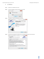
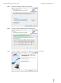
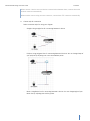
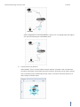
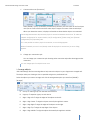
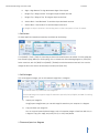
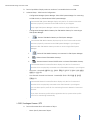
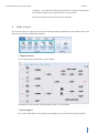
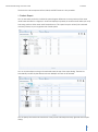
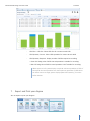
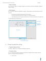
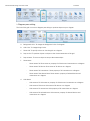
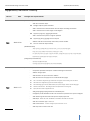
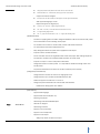
1
iPOLiS Network Design Tool User Guide Explains how to use iPOLiS Network Design Tool that helps designing network surveillance system with multiple Samsung Techwin network products. FOURTH EDITION | 12-2013 iPOLiS Network Design Tool User Guide Contents Contents CONTENTS ........................................................................................................................................................................................................... 2 WHAT IS IPOLIS NETWORK DESIGN TOOL? .............................................................................................................................................. 3 INSTALLING IPOLIS NW DESIGN TOOL....................................................................................................................................................... 3 1. 2. PC REQUIREMENT ....................................................................................................................................................................................... 3 INSTALLATION .............................................................................................................................................................................................. 4 FUNCTIONS ......................................................................................................................................................................................................... 6 1. 2. 3. 4. 5. 6. 7. 8. SCREEN COMPOSITION............................................................................................................................................................................... 6 NEW / SAVE / OPEN PROJECT ................................................................................................................................................................... 6 SELECT & ADD A DEVICE ............................................................................................................................................................................ 7 DRAW A DIAGRAM ...................................................................................................................................................................................... 9 CONFIGURE AN OBJECT PROPERTIES...................................................................................................................................................... 16 MAKE A REPORT ....................................................................................................................................................................................... 23 EXPORT AND PRINT YOUR DIAGRAM .................................................................................................................................................... 27 CHANGE THE APPLICATION SETTING ..................................................................................................................................................... 28 APPENDIX) REVISION HISTORY ...................................................................................................................................................................31 2 iPOLiS Network Design Tool User Guide What is iPOLiS Network Design Tool? What is iPOLiS Network Design Tool? iPOLiS NW Design Tool is a graphical drawing application that helps you to design network surveillance system with Samsung Techwin network products. With this application, you can do following: To search and select a desired product To design and draw network system diagram with analog/network product shapes To edit properties – description, IP configuration, video setup, etc and verify products information To simulate network bandwidth of transmitting/receiving per a product To print or export to image of network system diagram Installing iPOLiS NW Design Tool 1. PC requirement OS Windows XP SP3, Windows Vista, Windows 7, Windows 8 Prerequisite installation Microsoft .NET Framework 4 Client Profile CPU Pentium III CPU 1GHz or higher RAM 512MB or more Hard disk 1GB or more Video graphic card 1024 X 768 or higher, 32bit high color Supported language Korean, Chinese, Japanese, English, Polish, Romanian, Spanish, Turkish, French 3 iPOLiS Network Design Tool User Guide 2. Installing iPOLiS NW Design Tool Installation Step 1. Double click installation file to start. Step 2. Select the language you want to install, and click [OK]. Step 3. Click [Next >] when the installation wizard starts. Step 4. Read the license agreement carefully and click [I Agree] to proceed with the next step. 4 iPOLiS Network Design Tool User Guide Installing iPOLiS NW Design Tool Step 5. Choose the destination folder, and click [Install]. Step 6. The Wizard starts installing the iPOLiS NW Design Tool. Step 7. When the installation is completed, click [Finish] to complete the installation. 5 iPOLiS Network Design Tool User Guide Functions Functions 1. Screen composition iPOLiS NW Design Tool consist of menu, toolbox, diagram, and properties pane. 2. 1. Menu bar – Loaded with executable menu buttons 2. Filter toolbox – Provides product filtering and selection 3. Diagram – Draws system diagram by using product objects and connectors 4. Properties – Provides product information and its properties New / Save / Open project New To clear the current diagram and make it initialized, click [FILE] > [New Project]. 6 iPOLiS Network Design Tool User Guide Functions Save To save the current diagram including properties and products information, click [FILE] > [Save]. The project file is stored in *.sndt format. To save the project file in a desired location, select a folder in the Save dialog box. When you save an existing project, it saves the changes so far. Save As To save as a new project with the current diagram, click [FILE] > [Save As]. Even though it is an existing project file, it creates a new file in a user defined location. Open To open the original project file including system diagram and properties, click [FILE] > [Open]. In the Look in list or navigation pane, click the folder that contains the project file that you want to open. Recent Documents To display a list of files that you most recently used, click [FILE] > [Recent]. In the project list, click the file that you want to open. Sample Documents To display 5templates of system diagram, click [FILE] > [Samples]. In the template list, click the file that you want to open. 3. Select & Add a device To create your drawings, drag a device from toolbox onto the diagram pane. To search and select a device according to product specification 1) Click [Filter Toolbox] tab from toolbox pane. 2) Choose one of product category and its options, it displays search result with products satisfied the user selected options. Select one device from the list. You can verify its technical specification from [Product Information] 7 iPOLiS Network Design Tool User Guide Functions tab on [Properties] pane. 3) Select one of desired product from search result, and drag it onto a diagram pane. To select a device from entire list 1) Click [Toolbox] tab from toolbox pane. 2) Select a desired product category from [Shapes], it displays entire product list of the relevant category. Select one device from the list. You can verify its technical specification from [Product Information] tab on [Properties] pane. 3) Select one of desired product from search result, and drag it onto a diagram pane. Search To search devices with model name or some parts of model name. 1) Select [Search] from filter toolbox 2) Input model name or some parts of model name Select one device from the list. You can verify its technical specification from [Product Information] tab on [Properties] pane. 8 iPOLiS Network Design Tool User Guide 3) Functions Drag a device from search result list onto the diagram pane. To add a group of device To add multiple devices of same model, make a group of device. 1) Drag a device from toolbox onto the diagram pane. 2) Select a created device and select [Edit] button on the top of the device image. Then, dialog appears for setting the quantity of devices. 3) After enter or select the number of devices, click [SAVE] button. When you connect group device with switch, you can set the quantity of camera up to the number of usable ports. 4. Draw a diagram To select object on a diagram, click [HOME] > [Tool] > [Pointer], and with the selection arrow, click any objects that you want to select. Select one object Click one object. The selected object displays selection handles. Select multiple objects Click on the diagram and drag – a selection area appears. Surround around all the objects that you want to select. Or hold down the CTRL key and click each object. The selected objects are outlined by a temporary box with selection handles. To quickly select all objects on the diagram, press [CTRL + A] key. Copy/Cut/Paste/Delete objects 9 iPOLiS Network Design Tool User Guide Functions Copy and paste are two commands that make it simple to reuse objects, without having to recreate it from toolbox. 1) Select one or more objects from a diagram. 2) With objects selected, choose one of the following actions from [HOME] > [Clipboard] group. A. Paste: Visibly insert the object, which preceded [Cut] or [Copy]. B. Cut: Immediately remove the selected object from its original position, and later inserted when the [Paste] command is issued. C. Copy: Create a duplicate, and later inserted when the [Paste] command is issued. You can also use standard keyboard shortcuts, such as [CTRL + C] to copy and [CTRL + L] to paste. D. Delete: Erase the selected objects from a diagram. Move objects With the selection arrow – by clicking [HOME] > [Tool] > [Pointer], click and move the objects where you want it, release the mouse button. Connect between objects You can connect between two devices. Connector is drawing element that indicates which device is physically linked to which device. Objects and connectors together give the complete diagram. The connection type can be selected from [HOME] > [Connection Type], it indicates transmittable data rate. 10M – Network connector which has max. 10Mbps transmission speed. 100M – Network connector which has max. 100Mbps transmission speed 1G – Network connector which has max. 1Gbps transmission speed 10G – Network connector which has max. 10Gbps transmission speed Coaxial – Analog connector Wireless – Wireless network connection ETC – Common connector, such as HDMI, USB or Serial Cable When connect 2devices of analog type, connect them with analog (coaxial) connector automatically. When connect network camera/encoder and switch, connect them 100M connector automatically. 10 iPOLiS Network Design Tool User Guide Functions When connect 2 devices are used wireless communication between them, connect them with wireless connector automatically When need to connect using common connector, connect them ETC connector automatically. A. Choose style for connection Select connection style for using your diagram. Straight: Using straight line for connecting between 2 devices Polyline: Using polygonal line for connecting between 2 devices. You can change shape of your polyline by adjusting one or two intermediate points. Bezier: Using Bezier line for connecting between 2 devices. You can change angle of your Bezier line by adjusting two auxiliary points. 11 iPOLiS Network Design Tool User Guide B. Functions Spline: Using spline for connecting between 2 devices. You can change shape and angle of your spline by adjusting two intermediate points Connect with mouse [Pointer] Select [HOME] > [Tool] > [Pointer]. When an object selected, it provides visual cues that show you where connections can be made. Each point at which a connection can be made is marked with a connection point, as below figure shows in blue. Click one of connection points on an object, drag it to another object. 12 iPOLiS Network Design Tool User Guide C. Functions Connect with mouse [Connector] Select [HOME] > [Tool] > [Connector]. Position the [Connector] over the center of the first object until you see a red border around the entire object. Drag to the center of the second object. When you release the mouse, it displays red handles to show that the objects are connected. Connecting between two objects means physical connection between two devices. To make the network configuration for communication, use [IP configuration], [Video setup], and [Channel configuration] on [Properties] pane. If it is not possible to make a physical connection, an error dialog appears. When all network port are in use (already made all the physical connections), an error dialog appears. D. Change your connection style You can change your connection style choosing other connection style after selecting particular connection, You can change style of multiple lines at once Arrange objects iPOLiS NW Design Tool has manual guides to help ensure the objects in your diagram are arranged well. That helps make your drawing as clear as possible and give it a professional look. Select the objects you want to arrange, and click the arrangement option you want from [HOME] > [Arrange]. A. Group: To make a group from selected several devices. B. Ungroup: To separate a group to each device. C. Align > Align Left: To align the edges of the objects to the left D. Align > Align Center: To align the objects vertically through their centers. E. Align > Align Right: To align the edges of the objects to the right. F. Align > Align Top: To align the top edges of the objects. G. Align > Align Middle: To align the objects horizontally through their middles. 13 iPOLiS Network Design Tool User Guide H. Align > Align Bottom: To align the bottom edges of the objects. I. Bring to Top > Bring Forward: To bring the object forward one level. J. Bring to Top > Bring to Top: To bring the object to the front. K. Send to Back > Send Backward: To send the object backward one level. L. Send to Back > Send to Back: To send the object to the back. Functions It changes an object’s position in the stacking order so that one appears in front of another. Add a text It's often helpful and sometimes necessary to add text to the drawing. Click [HOME] > [Tool] > [Text]. Click and drag to draw an area where text to be added. Click the green edit box and start typing. When you finish typing, click on a blank area of the drawing diagram or press [ESC]. Select a text box, and click [Bold] from [HOME] > [Textbox] to make the text becomes bold. You can also change the font color and size of text with [Font Color] and [Font Size]. Add a images Such as background images, you can add external image files in a diagram. You cannot make any connection with image files iPOLiS NW Design tool support image file extension especially PNG, JPEG(JPG) and BMP for adding external images A. Import your image file Using [Import Image] button, you can add image file stored on your computer in a diagram. B. Copy and Paste your image file You can copy and paste clipboard images, such as Screenshot images or Data from MS Visio, in a diagram. Copy your image, and press [Ctrl+V] or click [Paste] button. Zoom and pan in a diagram 14 iPOLiS Network Design Tool User Guide Functions You can zoom in for a closer look at your drawing and move the diagram around (or "pan" the diagram) to view the section you want A. Pan a diagram Select [HOME] > [Tool] > [Pan]. A mouse pointer changes into finger shape. You can pan to view other sections of the diagram by dragging the mouse over the section you want to view B. Zoom a diagram Click zoom icon on the bottom of diagram pane. It includes a slider that sets the zoom level. [Auto Fit] button fits the diagram to the size of the current diagram. 15 iPOLiS Network Design Tool User Guide 5. Functions Configure an object properties You can setup a properties of an object which is a system component placed in a diagram. Select an object on a diagram and verify/edit information on [Properties] pane. The properties vary depending on the product category of the selected object. Or, select the device which you want to set properties and click the Advanced Setup icon for set up properties of single or multiple devices Setting properties depend on each product’s type. Network Camera A. Device Information: Basic information of a camera object. Name: Specify the name of camera. The default name is camera model number. Location #1 ~ #4: Specify the location where the camera is installed. According to a whole system diagram, up to 4-depth location can be specified. 16 iPOLiS Network Design Tool User Guide B. C. Functions Description: Input the relevant information on the camera. Quantity: Display the number of cameras for group object. IP Configuration: Network information of a camera object. Address Type: Specify one of network address type. IP Address: Enter network IP address. Subnet Mask: Enter subnet mask address. Gateway: Enter network gateway address. DNS Server: Enter DNS server address. Advanced Setup: Open the advanced setting window for video profile setting of a camera. Unit ID: Select ID of camera. Apply to others: Apply profiles to other selected camera. IP Assign: Set the network address of single device or multiple devices. Scene activity: Specify how complex scene and frequent movement the video has. If a video includes complex patterns or a lot of movements, select ‘HIGH’. Otherwise, the video includes simple background and rare movement, select ‘LOW’ Use: Select or clear whether the camera uses multiple profiles or not. Profile options (Codec/Resolution/Framerate/Compression/Bitrate Type/Bitrate): Specify video settings for each profile. Encoder A. Device Information: Basic information of an encoder object. Name: Specify the name of encoder. The default name is model number. Location #1 ~ #4: Specify the location where the encoder is installed. According to a whole system diagram, up to 4-depth location can be specified. B. C. Description: Input the relevant information on the encoder. Quantity: Display the number of cameras for group object. IP Configuration: Network information of an encoder object. Address Type: Specify one of network address type. IP Address: Enter network IP address. Subnet Mask: Enter subnet mask address. Gateway: Enter network gateway address. DNS Server: Enter DNS server address. Video Setup: Video profile setting of an encoder. Scene activity: Specify how complex scene and frequent movement the video has. If a 17 iPOLiS Network Design Tool User Guide Functions video includes complex patterns or a lot of movements, select ‘HIGH’. Otherwise, the video includes simple background and rare movement, select ‘LOW’ Use: Select or clear whether the encoder uses multiple profiles or not. Profile options (Codec/Resolution/Framerate/Compression/Bitrate Type/Bitrate): Specify video settings for each profile. Switch A. Device Information: Basic information of a switch object. Name: Specify the name of switch. Location #1 ~ #4: Specify the location where the switch is installed. According to a whole system diagram, up to 4-depth location can be specified. B. C. D. E. Description: Input the relevant information on the switch. Port Information Ports: Verify the number of ports of the switch. Port Speed (Mbps): Verify the transmission performance per port. Giga Port Information Giga Ports: Verify the number of Giga ports of the switch. Giga Port Speed (Mbps): Verify the transmission performance per Giga port. PoE Information PoE Support: Whether the switch provide PoE functionality. PoE Max Power (W): The maximum power consumption of PoE. PoE Port Number: The number of PoE ports of the switch. PoE+ Port Number: The number of PoE+ ports of the switch. Port Connection Status : Check and change condition of each port on switch. 18 iPOLiS Network Design Tool User Guide Functions Status: Display the connecting status of each port. Port Speed: Decide transmission speed of each port. You have a choice of port speed: 1Mbps or 1Gbps. Hardware/Software NVR A. Device Information: Basic information of an NVR object. Name: Specify the name of NVR. Location #1 ~ #4: Specify the location where the NVR is installed. According to a whole system diagram, up to 4-depth location can be specified. B. C. D. Description: Input the relevant information on the NVR. IP Configuration: Network information of an NVR object. Address Type: Specify one of network address type. IP Address: Enter network IP address. Subnet Mask: Enter subnet mask address. Gateway: Enter network gateway address. DNS Server: Enter DNS server address. Device Capabilities: Performance of the NVR. Channel: Verify the maximum number of channels to be connected to the NVR. HDD Size (GB): Specify the recording capacity of the NVR. Recording Bit Rate: Specify the recording throughput of the NVR. Channel Configuration: Specify camera/encoder to be connected each channel of NVR. Add Device: Resister selected devices for each channel. Connectable Network Cameras/Encoders displays only the list of camera and encoder which are physically connected to the NVR in your diagram. Apply to others: Apply profile setting to other selected camera. Name: Select a model name of device to be connected each channel. Ch > Video Setup: Specify one of profiles to be used in the NVR. When selecting a profile, its profile video setting appears. Ch > Camera Setup: Specify profile setting of the camera. 19 iPOLiS Network Design Tool User Guide Functions CMS A. Device Information: Basic information of a CMS object. Name: Specify the name of CMS. Location #1 ~ #4: Specify the location where the CMS is installed. According to a whole system diagram, up to 4-depth location can be specified. B. Description: Input the relevant information on the CMS. IP Configuration: Network information of a CMS object. Address Type: Specify one of network address type. IP Address: Enter network IP address. Subnet Mask: Enter subnet mask address. Gateway: Enter network gateway address. DNS Server: Enter DNS server address. C. Device Capabilities: Display maximum number of connectable devices for live monitoring. D. Advanced Setup – CMS Device Configuration: Open the advanced setting window for CMS. Device>Add Device: Resister selected devices for monitoring Connectable Network Cameras/Encoders displays only the list of camera and encoder which are physically connected to the CMS in your diagram. CMS Live Channel>CMS Live Channels: Resister selected devices for live monitoring Connectable Network Cameras/Encoders displays only the list of camera and encoder which are physically connected to the CMS in your diagram. You can select specific profile for live monitoring from each device. 20 iPOLiS Network Design Tool User Guide Functions If you don’t choose any profile before registration device, system resister profile no.2 for live monitoring automatically. SSM All of setting for SSM(Samsung Security Manager) system is implemented in SSM-Console. A. Device Information: Basic information of a SSM object. Name: Specify the name of SSM. Location #1 ~ #4: Specify the location where the SSM is installed. According to a whole system diagram, up to 4-depth location can be specified. B. Description: Input the relevant information on the SSM. SSM Configuration: Network information of a SSM object. SSM Type: Displays which type of SSM the object is. i. SSM-System Manager: It manages SSM Media Gateways. Up to 4 Media Gateways are connectable. ii. SSM-Media Gateway: It receives media data by directly connecting with camera, NVR, and encoder. iii. SSM-Console: It provides monitoring environment. It links to SSM System Manager and views video through Media Gateway registering on the System Manager. iv. SSM-Standalone: Installing and using all the System Manager, Media Gateway, and Console in a single PC. Console Setup: Configurable when [SSM-Console] or [SSM-Standalone] selected. Specify one of SSM System Manager physically connected. Select cameras, NVRs, and encoders to be monitored from the list. Media Gateway Setup: Configurable when [SSM-Media Gateway] or [SSM-Standalone] selected. Select cameras, NVRs, and encoders from the list. System Manager Setup: Configurable when [SSM-System Manager] or [SSM-Standalone] selected. Select one of Media Gateway from the list. C. IP Configuration: Network information of a SSM object. Address Type: Specify one of network address type. IP Address: Enter network IP address. Subnet Mask: Enter subnet mask address. Gateway: Enter network gateway address. DNS Server: Enter DNS server address. 21 iPOLiS Network Design Tool User Guide Functions D. Device Capabilities: Display maximum number of connectable devices on SSM. E. Advanced Setup – SSM Console Configuration Configuration Manager>System Manager: Select SSM-System Manager for connecting to SSM Console, or, delete selected SSM-System Manager. Connectable SSM-System Manager displays only the list of camera and encoder which are physically connected to the SSM Console in your diagram. Only single SSM-System Manager is able to connect to single SSM Console. Configuration Manager>Media Gateway: Set SSM-Media Gateway for connecting to SSM-System Manager. i. : Resister SSM-Media Gateway to SSM-System Manager Connectable SSM-Media Gateway displays only the list of camera and encoder which are physically connected to the SSM-System Manager in your diagram. Maximum 4EA SSM-Media Gateway are able to connect single SSM-System Manager. ii. : Delete all SSM-Media Gateways are connected in SSM-System Manager. iii. : Delete selected SSM-Media Gateways. iv. : Resister Network Camera/NVR/Encoder in selected SSM-Media Gateway. Connectable Network Cameras/Encoders displays only the list of camera and encoder which are physically connected to the SSM-Media Gateway in your diagram. Device List : Console에 연결되어 있는 장비의 목록을 확인하고 각 장비의 상세 설정을 변경할 수 있습니다. Live Channels>Console Live Channels : Console에서 라이브 모니터링을 할 장비를 등록합니다. Connectable Network Cameras/Encoders displays only the list of camera and encoder which are physically connected to the SSM Console in your diagram. You can select specific profile for live monitoring from each Network Camera and Encoder. If you don’t choose any profile before registration device, system resister profile no.2 for live monitoring automatically. DVR / Analogue Camera / ETC A. Device Information: Basic information of object. Name: Specify the name of object. 22 iPOLiS Network Design Tool User Guide Functions Location #1 ~ #4: Specify the location where the device is installed. According to a whole system diagram, up to 4-depth location can be specified. 6. Description: Input the relevant information on the object. Make a report You can issue a report in order to make it easy to understand system configuration of your diagram. There are 4 different types of report in [REVIEW] > [Reports]. Diagram Report You can see an entire system layout of your diagram. The diagram can be exported as PNG and BMP format. It is also printable. Device Report You can see entire object list included in system diagram. The list includes each object properties. 23 iPOLiS Network Design Tool User Guide Functions You can sort the objects as drag a column header onto the top of the report dialog. Then the list automatically reorders by the selected columns. Multiple columns can be selected. You can specify the column list to be shown. Click [Choose Columns] on the top right side of the report dialog. 24 iPOLiS Network Design Tool User Guide Functions The device list can be exported as Excel, Word, and PDF format. It is also printable. Product Report You can see entire product list included in system diagram. When two or more products of the same model name included in a diagram, it counts and displays its quantity. It would be useful when you verify how many products of the same model name there are. This report has price column [unit cost/total cost/sum] column, so you can get the cost of total system. You can sort the objects as drag a column header onto the top of the report dialog. Then the list automatically reorders by the selected columns. Multiple columns can be selected. You can specify the column list to be shown. Click [Choose Columns] on the top right side of the report dialog. 25 iPOLiS Network Design Tool User Guide Functions The device list can be exported as Excel, Word, and PDF format. It is also printable. Bandwidth Report The bandwidth usage chart to be shown indicates the inbound and outbound bandwidth of the current system diagram. The bandwidth report can be exported as Word and PDF format. It is also printable. The current release only supports the inbound and outbound bandwidth of Samsung Techwin products. The bandwidth for switch will be supported later. Storage Report Calculate HDD quantities for current system from recording duration and HDD size. 26 iPOLiS Network Design Tool User Guide Functions - HDD Size > HDD Size : Select HDD Size for connect to each NVR. - HDD Quantity > Current : Select HDD quantities for connect to each NVR. - HDD Quantity > Required : Display number of HDDs required to recording. > Green Cell: Setting value of HDD size and quantities is suitable for recording. > Red Cell: Setting value of HDD size and quantities is NOT suitable for recording. When appear red cell, system displays a required minimum quantities of HDD. If the required minimum quantities over than maximum quantities of HDD which are able to connect to single, system displays [Max HDD Quantity: ] for notice NVR’s limitation. 7. Export and Print your diagram You can export or print your diagram. 27 iPOLiS Network Design Tool User Guide Functions Export to Image You can save your diagram as a standard image file in PNG format in directly from [REVIEW] > [Diagram] > [Export to Image]. Print Diagram You can print your diagram. Click [REVIEW] > [Diagram] > [Print Diagram]. In the [Print] dialog box, do the following: In the preview, see how the diagram will look when printed. In the [Print], select the printer that you want (if it is not already selected). Under [Settings], specify the diagram orientation, one of landscape and portrait, and its paper size. Click [Print] when you are ready to print. 8. Change the application setting Program language setting Click [FILE] > [Options]. You can change the language of application. Task pane setting You can customize the task pane arrangement of application. Changed task pane setting is saved and applied to restarting application automatically. A. Move a pane 28 iPOLiS Network Design Tool User Guide Functions To move each pane, drag the pane title or title tab to the new location. If you drag the pane arrows appears to indicate where to move. When you drop the pane on an arrow, it becomes docked. B. Show/Hide each pane Click [VIEW] > [Window]. You can show each pane by click the control as selected button. You can close the pane by click again as unselected button. Layout resetting Click [VIEW] > [Window] and select [Reset layout] button. This reset the changed task pane to default setting. 29 iPOLiS Network Design Tool User Guide Functions Diagram pane setting The lines of the grid crisscross on diagram pane help you position shapes on your diagram. A. Background Color: To change the background color of a diagram. B. Grid Color: To change the grid color. C. Show Grid: To specify to show or clear the grid on a diagram. D. Snap to Grid: To position objects or objects to the closest intersection of the grid. E. Snap to Items: To move an object to snap to the nearest object. F. Show Name Show name of all: Show name or property of all devices and connections on a diagram Show name of all devices: Show name of all devices on a diagram Show name of all connections : Show property of all connections on a diagram Show name of the selected item: Show name or property of selected devices and connections on a diagram G. Hide Name Hide name of all: Hide name or property of all devices and connections on a diagram Hide name of all devices: Hide name of all devices on a diagram Hide name of all connections: Hide property of all connections on a diagram Hide name of the selected items: Hide name or property of selected devices and connections on a diagram 30 iPOLiS Network Design Tool User Guide Appendix) Revision history Appendix) Revision history Version Date Changes and improvements [New features] Add new connection styles. Add a new function to show/hide the name of objects including connections. Add a new function to insert images on the diagram. 2013-12-20 support to png, bmp, jpg/jpeg file formats. Add a new function to paste a image in clipboard. 1.3.0 Straight, Polyline, Spline and Beizier support png, bmp, jpg/jpeg and visio objects. Add the Find tab to search shape more easily in Filter ToolBox. Ctrl+F to search the object directly. [Modified features] After saving a sample file as another name, can't save the file again. Does not save Z-Order information of objects in a file. If it take much time to open a report window, change mouse cursor to a busy indicator. Peformance optimization of Report window. [Changed/Improved features] Remove ToolBox Window. Change status of PoE properties of Switch ediatable. [New features] 1.2.0 Output the separated result report on BW calculating for each device Add the storage report Add automatic set-up function for IP address Add new function and apply new UI on Advanced Setup page 2013-11-15 NVR - Add channel configuration page. Add function for apply the channel setting across-the-board. CMS- Add device configuration page and live channel setting page SSM- Add setting page of Console, Media Gateway and system manager. Add live channel setting page. Network Camera/Encoder - Add setting IP address and profile for device in the group Display disconnect status of registered devices Add grouping/ungrouping function for selected objects Change the pointer between 'Pointer' and 'Connector' by double-click space on diagram Add reference guide document and improve sample project file. Add Shape : Wireless AP, Cloud, SSM Mobile, iPOLiS Mobile, Video Wall, SPD-400, SVM Add new connection type : Wireless, ETC Add Custom Switch - It’s able to change the port number from 1 to 512. Add Help menu on main menu bar 31 iPOLiS Network Design Tool User Guide Appendix) Revision history Change the position of help button from Home menu to main menu bar. Add menu button for online tutorial, Home page, Contact us and About Support scroll bar for diagram If all objects are not able to display on the diagram, scroll bar appear automatically Add supported language : French Keyboard Support for diagram (en) arrow key, Ctrl + arrow key - slightly nudge the selection Ctrl + Shift + arrow key - moved the selection further than arrow key F2 - begins editing diagram item Ctrl + G - groups the selected items // Ctrl + U – ungroup the selected groups [Modified features] 1.2.0 2013-11-15 Fix failure to applying data issue when change bandwidth for CBR on Camera/Encoder profile. Fix font information issue on loading saved project. Fix connection error when re-connect other product with existed connection. Fix copied object information disappeared issue. Keep setting information of system when copy&paste some objects Improve scenario of NVR calculation Fix non-activation issue for saving button when create new project after loading sample file. Fix automatic connection error between SSM and Switch by coaxial cable Improve UI of report - Device and product information Change the scenario of camera profile - It is impossible to disable and change codec of #1 and #2 profile. Fix position initialization issue when user set the connection point manually [Changed/Improved features] Change maximum number of cameras on single group to 64 Change maximum port number of Stackable Switch to 288 Disable to support save files from v1.0 and v1.1 Change component information of video at NVR, CMS and SSM Delete DHCP setting option of IP address [New features] 1.1.0 2013-08-30 Support Multi language Support Multi documents (Max. 10) Support group object Add analog camera/DVR/Mobile object Add ruler on diagram Add analog connector Support a list of recent files Support a list of sample files Support to reset layout Add [price] column on device list report 32 iPOLiS Network Design Tool User Guide Appendix) Revision history [Modified features] Fix the autoalignment error, when resize toolbox window Fix the setting error of VBR/CBR in video setup of network camera/encoder [Changed/Improved features] 1.1.0 2013-08-30 Change UI theme of application Change UI of some menus Change image of some objects Change video setting to get H.264 profile automatically , when connect network camera to NVR, CMS and SSM Change object image to be able to resize 1.0.0 2013-07-15 Change copy/paste object to include properties The first official release 33