1
-
Océ
VarioPrint®
4110/4120
Enjoy productivity
o
User manual
Operating
information
Copyright
© 2008-2009 Océ
All rights reserved. No part of this work may be reproduced, copied, adapted, or transmitted
in any form or by any means without written permission from Océ.
Océ makes no representation or warranties with respect to the contents hereof and specifically disclaims any implied warranties of merchantability or fitness for any particular purpose.
Further, Océ reserves the right to revise this publication and to make changes from time
to time in the content hereof without obligation to notify any person of such revision or
changes.
Edition: 2009-5
Trademarks
Trademarks
List of trademarks
Océ, Océ VarioPrint® 4110/4120 , Image logic digital scan technology, DocWorks,
PRISMAprepare, PRISMAaccess, PRISMAproduction PoD, PRISMAsatellite, Document
Designer, PRISMAoffice, CountLogic, JobSubmitIt are registered trademarks of Océ.
Adobe, Acrobat, Reader Distiller PostScript (PS) and Portable Document Format (PDF)
3™ are registered trademarks of Adobe Systems Incorporated.
PCL is a registered trademark of Hewlett-Packard Company.
IPDS is a registered trademark of International Business Machines Corporation.
Excel is a trademark of Microsoft Corporation.
Products in this publication are referred to by their general trade names. In most, if not
all cases, these designations are claimed as trademarks or registered trademarks of their
respective companies.
3
Contents
Contents
Chapter 1
Introduction.........................................................................................................9
Notes for the reader.................................................................................10
Introduction to the Océ VarioPrint® 4110/4120 ....................................12
Available documentation.........................................................................13
Chapter 2
Power information............................................................................................15
The power modes....................................................................................16
Turn on the machine................................................................................19
Shut down the machine...........................................................................20
Chapter 3
Overview of the system components.............................................................23
Introduction to the main system components and finishing devices...24
The operator panel...................................................................................27
The operator attention light....................................................................30
The output locations................................................................................32
The paper module....................................................................................35
The dual paper tray (optional).................................................................37
Chapter 4
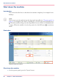
Work with the operator panel.........................................................................41
Introduction...............................................................................................42
The dashboard....................................................................................42
The Schedule view...................................................................................44
Introduction to the 'Schedule' view..................................................44
Load the media...................................................................................48
Stop a print job...................................................................................50
The Jobs view...........................................................................................53
Introduction to the 'Jobs' view..........................................................53
The print function...............................................................................57
Schedule a waiting job for printing.............................................57
Reprint a job..................................................................................59
Give priority to a scheduled job..................................................61
Delete a job...................................................................................62
Print a scheduled job later...........................................................64
Make a proof.................................................................................66
Print the job parameters..............................................................68
Bundle and split jobs....................................................................70
Print all the jobs for which the media are available..................74
4
Contents
Print the jobs that have a label....................................................75
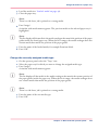
Check and change the job properties...............................................77
Change the number of sets..........................................................77
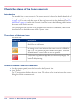
Check the first set.........................................................................80
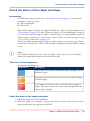
Change the media.........................................................................83
Change the output location.........................................................86
Change the number of staples....................................................88
Change the sorting method.........................................................90
Change the type of offset stacking..............................................92
Shift the margin or image............................................................94
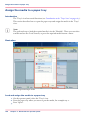
The Copy/Scan view.................................................................................96
Introduction to the Copy/Scan view..................................................96
Original input on the glass plate or into the ADF..........................100
Access other functions during a copy job or scan job..................103
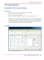
The zoom behaviour........................................................................106
The copy function.............................................................................109
Description of the copy job settings.........................................109
Make a basic copy......................................................................118
Combine subsets into one document ......................................120
Use the templates.......................................................................124
Rename a copy job.....................................................................127
Copy non-standard size originals..............................................129
Scan now and print later............................................................131
Punch or staple the output.........................................................133
The scan function.............................................................................135
Introduction to the scan function..............................................135
The configuration of the scan-to-file function..........................137
The configuration of the scan-to-email function......................138
The scan profiles file..................................................................141
Description of the scan job settings..........................................148
Create a scan job........................................................................154
Correct an image........................................................................157
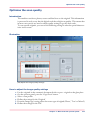
Optimise the scan quality..........................................................159
Combine subsets into one file...................................................161
The Trays view.......................................................................................165
Introduction to the 'Trays' view......................................................165
Assign the media to a paper tray....................................................168
The System view....................................................................................170
The Printer section...........................................................................170
Introduction to the 'Printer' section..........................................170
Check the status of the toner reservoir.....................................172
Check the status of the staple cartridges..................................173
Reset the day counters...............................................................174
Find the meter readings.............................................................176
5
Contents
The Setup section.............................................................................177
Introduction to the 'Setup' section............................................177
Work with the workflow profiles...............................................179
Change the language.................................................................184
Change the warning time...........................................................186
Truncate the job name...............................................................189
Make an intermediate check print.............................................191
Change the accounting settings................................................193
Disable the double-sheet detection...........................................197
The Media section............................................................................199
Introduction to the 'Media' section...........................................199
Introduction to the media handling..........................................201
Add temporary media to the 'Media catalogue'......................203
The Transaction section (optional).................................................205
Introduction to the 'Transaction' section .................................205
Activate the transaction printing function................................209
Shift the image in the transaction printing mode....................211
Handle the media messages......................................................213
Create a transaction setup.........................................................216
Chapter 5
The accounting function................................................................................219
About the accounting function..............................................................220
Enter an account ID per job...................................................................222
Chapter 6
Optional finishers............................................................................................225
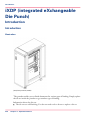
iXDP (integrated eXchangeable Die Punch).........................................226
Introduction.......................................................................................226
Introduction.................................................................................226
Operating information.....................................................................228
Main parts...................................................................................228
Die sets available........................................................................231
Empty the chip tray....................................................................232
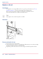
Replace a die set.........................................................................234
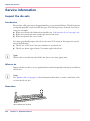
Service information..........................................................................236
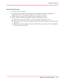
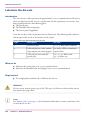
Inspect the die sets.....................................................................236
Lubricate the die sets.................................................................238
Troubleshooting.........................................................................240
Specifications..............................................................................244
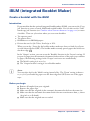
iBLM (integrated Booklet Maker)..........................................................245
Create a booklet with the iBLM.......................................................245
Chapter 7
Keep the printer running................................................................................249
Finisher: Add staples..............................................................................250
6
Contents
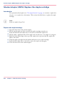
Stacker/stapler (iMFS): Replace the staple cartridge...........................256
iBLM (Booklet maker): Replace the stapler cartridges........................257
Add toner................................................................................................258
Troubleshooting.....................................................................................261
Appendix A
Miscellaneous..................................................................................................263
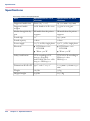
Product specifications............................................................................264
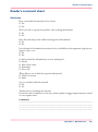
Reader's comment sheet ......................................................................267
Addresses of local Océ organisations .................................................269
7
Contents
8
Chapter 1
Introduction
Notes for the reader
Notes for the reader
Introduction
This manual helps you to use the Océ VarioPrint® 4110/4120 . The manual contains a
description of the product and guidelines to use and operate the Océ VarioPrint®
4110/4120 .
Definition
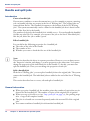
Attention Getters
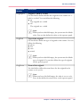
Parts of this manual require your special attention. These parts can provide the following:
■ Additional general information, for example information that is useful when you
perform a task.
■ Information to prevent personal injuries or property damage.
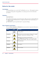
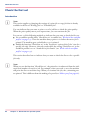
Note, Attention and Caution
The words Note, Attention and Caution draw your attention to important information.
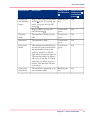
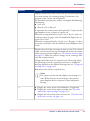
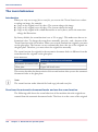
Overview of the attention getters#
Word
10
Icon
Indicates
Note
Tips or additional information about the correct use
of the product.
Attention
Information to prevent property damage, for example
damage to the product, documents or files.
Caution
Information to prevent personal injuries.
The Caution indication has several icons that warn
against various hazards. The icons are shown below.
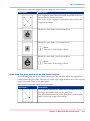
Caution
General hazard
Caution
Hot surface
Caution
Electric shock
Chapter 1 - Introduction
Notes for the reader
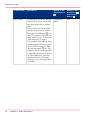
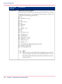
Word
Icon
Indicates
Caution
Moving parts
Caution
Laser beam
The use of heat-resistant gloves is mandatory when you
carry out the actions concerned.
Safety information
The safety information for this product is included in a separate manual with the title
Safety information. This manual is part of the documentation set that you received with
your product.
Chapter 1 - Introduction
11
Introduction to the Océ VarioPrint® 4110/4120
Introduction to the Océ VarioPrint® 4110/4120
Introduction
The Océ VarioPrint® 4110/4120 is a professional, productive modular printer. The
machine supports several finishing devices. The machine is targeted at productive printing
environments and central repros. You can use the machine for the following types of jobs.
■ Document printing
■ Stream printing
■ Transaction printing (optional)
■ Copy jobs
■ Scan jobs
This section gives a short description of the main features of the machine.
Note:
Not all the configurations mentioned in this user manual are available worldwide. Please
contact your local dealer for the available configurations in your country.
Overview of the main features
The main features of the machine are:
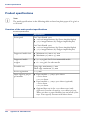
■ A sustained print speed of 106 - 120 images per minute (A4 80 g/m² / Letter 20 lb
bond). This depends on your configuration
■ Extensive configuration possibilities, for example the addition of many different finishing devices like a stacker/stapler, a puncher or a booklet maker
■ The support of a large range of media, media sizes and media weights
■ An excellent print quality
■ The possibility to process textured media
■ The support of PostScript 3, PCL6, PDF 1.7 in document printing
■ The support of streaming PCL5e and IPDS in transaction printing
■ An advanced scheduling concept on the operator panel to keep the machine running
12
Chapter 1 - Introduction
Available documentation
Available documentation
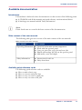
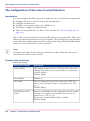
Introduction
This machine is delivered with a documentation set that consists of the following items.
■ A CD-ROM with all the manuals and quick reference cards mentioned below.
■ A hardcopy user manual entitled 'Safety information'.
Note:
Please check www.oce.com for the latest version of the documentation.
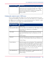
Main content of the user manuals
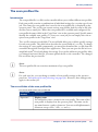
The following table gives an overview of the main content of the user manuals.
Main content of the user manuals#
User manual
Main content
Operating information
■
■
■
■
■
Safety information
■
■
Overview of the main system components
Work with the operator panel
Carry out print jobs, copy jobs and scan jobs
Handle and manage the jobs on the operator panel
Add media, toner and staples
Instructions for safe use
Safety data sheets
Available quick reference cards
The following quick reference cards are available:
■ How to make a basic copy
■ How to scan now and print later
■ How to carry out scan-to-email jobs
■ How to carry out scan-to-file jobs
Chapter 1 - Introduction
13
Available documentation
14
Chapter 1 - Introduction
Chapter 2
Power information
The power modes
The power modes
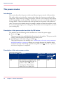
Introduction
This section describes the power switches and the main power modes of the machine.
The table in this section describes, among other things, the low-power mode and the
sleep mode. These modes are energy save modes. You can set the timers for these modes
in the Settings Editor on the controller. Furthermore, you can set a calendar timer in the
Settings Editor. Then the machine will wake up from the sleep mode at the indicated
time. You can use the calendar timer for example to make sure that the machine is ready
for use at the beginning of your working day. The machine can warm up before you start
your working day.
Description of the power switch and the On/Off button
The machine has the following switch and button to control the power supply.
■ Power switch
The power switch is located behind the front door of the machine. The power switch
connects and disconnects the machine to the mains power.
■ On/Off button with amber and green LEDs
.
The On/Off button on the machine (see ‘Introduction to the main system components
and finishing devices’ on page 24) allows you to toggle between the stand-by mode
and the sleep mode. This is only possible if the power switch is in the '1' position
and the start-up phase is completed.
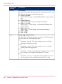
Description of the main power modes
The main power modes#
16
Power mode
Description
Status of the
On/Off button
Status of the
Hold button
and Release
button
Off
The machine is completely off.
The power switch is in the 'O'
position. There is no power
consumption. The machine
cannot receive or print jobs.
Off
Off
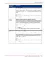
Chapter 2 - Power information
The power modes
Power mode
Description
Status of the
On/Off button
Status of the
Hold button
and Release
button
Starting up
(divided into 2
stages)
Stage 1: After you put the power
switch in the 'I' position, but
before you press the On/Off
button .
Blinking amber
Off
Stage 2: After you press the
On/Off button .
Continuous
green
On
Stand-by
mode
The machine is ready to print
jobs.
Continuous
green
On
Run mode
The machine is busy.
Continuous
green
On
Low-power
mode
The machine automatically enters the low-power mode when
the machine has been in the
stand-by mode for a defined
time and no button was pressed.
The machine wakes up when a
job arrives in the list of 'Scheduled jobs' or when you press a
button. The machine will start
to warm up.
Continuous
green
On
Going into
sleep mode
The machine is preparing to go
into the sleep mode.
Blinking amber
On
Chapter 2 - Power information
17
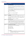
The power modes
18
Power mode
Description
Status of the
On/Off button
Status of the
Hold button
and Release
button
Sleep mode
The machine automatically goes
from the low-power mode into
the sleep mode after a defined
time.
You can also put the machine
into the sleep mode manually.
Press the On/Off button to do
this. The machine will enter the
sleep mode as soon as the list of
'Scheduled jobs' is empty.
The machine will wake up from
the sleep mode when you press
the On/Off button or when
the calendar timer expires. The
machine will also wake up when
a printable job arrives in the list
of 'Scheduled jobs', provided
that the function 'Automatic
wake-up' in the Settings Editor
is enabled.
Continuous
amber
Off
Chapter 2 - Power information
Turn on the machine
Turn on the machine
Introduction
This section describes how to turn on the machine when the machine is completely off.
Note:
When the machine is in the sleep mode (see ‘The power modes’ on page 16), you must
press the On/Off button to wake up the machine.
Turn on the machine
1. Put the power switch behind the front door of the machine in the 'I' position.
The On/Off button blinks amber while the machine and the controller start up.
Wait until the operator panel asks you to press the On/Off button .
2. Press the On/Off button .
The On/Off button is continuous green.
The machine warms up.
Chapter 2 - Power information
19
Shut down the machine
Shut down the machine
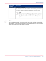
Introduction
This section describes how to shut down the machine completely, for example for the
holidays.
Note:
If you want to put the machine into the sleep mode manually (see ‘The power modes’ on
page 16), for example at the end of a working day, you must press the On/Off button
. Then the machine will go into the sleep mode as soon as the list of 'Scheduled jobs'
is empty. When the machine is in the sleep mode, the On/Off button is continuous
amber.
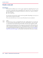
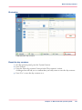
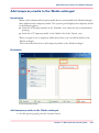
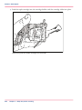
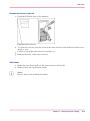
Illustration
[10] Shut down the machine
Shut down the machine
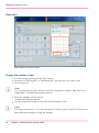
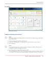
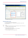
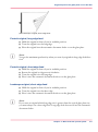
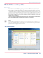
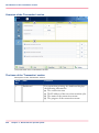
1. On the operator panel, press the 'System' button.
20
Chapter 2 - Power information
Shut down the machine
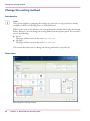
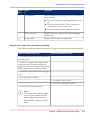
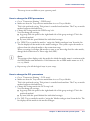
2. Press the 'Setup' button.
3. Press the 'Shut down system' button in the 'User interface' section.
A dialogue box asks you to confirm that you really want to shut down the machine.
4. Press 'Yes'.
A message indicates when the shutdown will begin. Wait until the following has happened.
■ The Hold button
and the Release button are off
■ The On/Off button
blinks amber
■ The screen of the operator panel is off.
5. Put the power switch
behind the front door of the machine in the 'O' position.
Chapter 2 - Power information
21
Shut down the machine
22
Chapter 2 - Power information
Chapter 3
Overview of the system
components
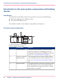
Introduction to the main system components and finishing devices
Introduction to the main system components and finishing
devices
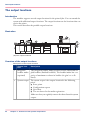
Introduction
The illustrations and tables in this section provide an overview of the following:
■ The main components of a default system
■ The optional finishing devices.
Please follow the links in the tables for comprehensive information.
The main system components
1
2
1
2
3
4
3
5
4
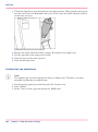
[11] The main system components
The main system components#
24
Component
Function
1
Operator panel
The operator panel helps you with your daily
work, for example the scheduling of the jobs.
Furthermore, the operator panel helps you to solve
errors (see ‘The operator panel’ on page 27).
2
Operator attention
light (optional)
The (optional) operator attention light enables
you to check the status of the system from a distance (see ‘The operator attention light’ on page
30).
3
Engine module
The engine module contains the components that
print the media. Access to the engine module is
only required when a paper jam occurs or when
maintenance is required.
Chapter 3 - Overview of the system components
Introduction to the main system components and finishing devices
Component
Function
4
Paper module
The default configuration of the system contains
1 paper module with 4 paper trays. The paper trays
contain the media that will be printed. You can
add 1 more paper module to the default configuration to increase the media input capacity (see
‘The paper module’ on page 35).
5
Stacker/stapler
The stacker/stapler supports a large number of
media sizes (see ‘The output locations’ on page 32).
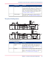
The optional finishing devices
7
6
1
1
2
2
3
3
4
4
1
1
2
2
3
3
4
4
9
8
10
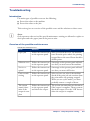
[12] The optional finishing devices
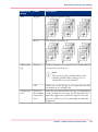
The optional finishing devices#
Component
Function
6
Integrated booklet
maker
The integrated booklet maker is an output location
on top of the engine module. The integrated
booklet maker can create simple booklets (see ‘The
output locations’ on page 32).
7
Finisher
The finisher on top of the stacker adds output capacity to your system. The finisher can staple the
jobs (see ‘The output locations’ on page 32).
Chapter 3 - Overview of the system components
25
Introduction to the main system components and finishing devices
26
Component
Function
8
Puncher
The puncher can make holes in the prints. The
number of holes depends on the die set that is installed (see ‘The output locations’ on page 32).
9
Stacker
The stacker adds output capacity to your system.
The stacker can not staple the jobs. (see ‘The output
locations’ on page 32).
10
Puncher/folder
The puncher/folder can make holes in the prints.
Furthermore, the puncher/folder can fold the
prints (see ‘The output locations’ on page 32).
External finishers
The machine supports several external finishers.
These finishers are not indicated in the illustrations. See the user manuals of these devices for
more information.
Chapter 3 - Overview of the system components
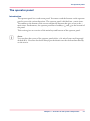
The operator panel
The operator panel
Introduction
The operator panel is a touch screen panel. You must touch the buttons on the operator
panel to access the various functions. The operator panel is divided into 5 main views.
The taskbar at the bottom of the screen contains the buttons that give access to the 5
main views. Furthermore, the operator panel has 2 hardkeys ( and ) at the bottom of
the panel.
This section gives an overview of the main keys and buttons of the operator panel.
Note:
You can clean the screen of the operator panel with a 50% mix of water and isopropyl
alcohol (K2). Use a lint-free cloth. Always put the cleaner onto the cloth and not directly
on the screen.
Chapter 3 - Overview of the system components
27
The operator panel
Illustration
[13] The operator panel
The main components of the operator panel
The main components of the operator panel#
1
Component
Function
Hold key
■
■
■
28
Chapter 3 - Overview of the system components
Put the machine on hold
Stop printing after a set
Stop printing as soon as possible (see ‘Stop
a print job’ on page 50).
The operator panel
2
Component
Function
Release key
■
■
Allow the machine to print
Resume printing when the machine is on
hold.
3
'Schedule' button
Access the 'Schedule' view (see ‘Introduction
to the 'Schedule' view’ on page 44).
4
'Jobs' button
Access the 'Jobs' view (see ‘Introduction to the
'Jobs' view’ on page 53).
5
'Copy/Scan' button
Access the 'Copy/Scan' view (see ‘Introduction
to the Copy/Scan view’ on page 96).
6
'Trays' button
Access the 'Trays' view (see ‘Introduction to
the 'Trays' view’ on page 165).
7
'System' button
Access the 'System' view
(see ‘Introduction to the 'Printer' section’ on
page 170).
(see ‘Introduction to the 'Setup' section’ on page
177).
(see ‘Introduction to the 'Media' section’ on page
199).
Chapter 3 - Overview of the system components
29
The operator attention light
The operator attention light
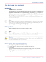
Introduction
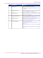
The operator attention light informs you about the status of the machine. To improve
the productivity, the operator attention light can warn you some time before the machine
stops. You can set the warning time on the operator panel (see ‘Change the warning time’
on page 186).
The operator attention light contains 3 lights (red, orange and green) that indicate the
current status of the machine. The colours of the lights match the status that is currently
indicated on the operator panel. For example, when operator interaction is required soon,
both the dashboard (see ‘The dashboard’ on page 42) and the operator attention light will
display an orange warning. The dashboard displays a message with the required action.
This section describes the meaning of the colours of the operator attention light.
[14] The operator attention light
Status colours
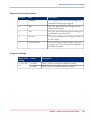
The colours of the operator attention light#
30
Colour
Description
Red
The machine has stopped, for example because a required
media type is not available or an error has occurred.
Operator attention is required now.
Orange
The machine will stop soon, for example because an output
location is almost full. The orange light lights up when the
machine reaches the warning time.
Operator attention is required soon.
Chapter 3 - Overview of the system components
The operator attention light
Colour
Description
Green
The machine is busy printing. The machine can print
longer than the defined warning time.
Operator attention is not required.
All lights off
The machine is idle. There are no jobs scheduled for
printing.
Chapter 3 - Overview of the system components
31
The output locations
The output locations
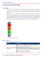
Introduction
The machine supports several output locations for the printed jobs. You can extend the
system with additional output locations. The output locations are the locations that can
receive the prints.
This section describes the possible output locations.
Illustration
4
3
1
2
5
1
1
2
2
3
3
4
4
6
7
[15] The output locations
Overview of the output locations
Description of the output locations#
Output location
Description
1
Integrated
booklet maker
(optional)
The integrated booklet maker produces sorted, folded and stapled booklets (finished booklets). The booklet maker has a capacity of maximum 20 sheets in booklet (80 g/m² or 20 lb
bond).
2
System output The system output is the output location for the following
prints.
■ Error prints
■ Configuration reports
■ Job tickets
■ The test sheets for the media registration.
Make sure that you regularly remove the sheets from the system
output.
32
Chapter 3 - Overview of the system components
The output locations
3
Output location
Description
Finisher (optional)
The optional finisher contains the following output trays.
■ 3 output trays
■ 1 upper output (see number 6 below)
The finisher contains 2 staple cartridges to staple the jobs. The
3 output trays can receive A4, Letter and similar media sizes.
Stapled jobs (A4, Letter and similar media sizes only) go into
the output trays. The total capacity of the output trays is 4,500
sheets (80 g/m² or 20 lb bond).
Note:
The output trays cannot receive tab sheets.
4
Finisher upper
output (optional)
The finisher upper output is part of the finisher. The upper
output can receive all formats. However, the upper output is
mainly intended for large media or jobs with mixed size media.
The maximum capacity of the upper output is 500 sheets (80
g/m² or 20 lb bond).
Note:
The upper output does not contain staple cartridges.
Therefore, the upper output cannot be the output location for jobs that require staples.
5
Stacker/stapler
upper output
The upper output is the upper tray of the stacker/stapler. The
capacity of the upper output is 250 sheets (80 g/m² or 20 lb
bond).
6
Stacker/stapler
lower output
The optional stacker/stapler contains 1 staple cartridge to staple
the jobs. The staple cartridge can staple your document with 1
or 2 staples. The stacker/stapler can stack and staple various
media sizes. The device supports the stapling of mixed media
sizes, as long as the width of the media is the same. The capacity
of the lower tray is 2,000 sheets (80 g/m² or 20 lb bond).
7
Stacker (optional)
The optional stacker has a capacity of 6,000 sheets, in 2 stacks
of 3,000 sheets each (80 g/m² or 20 lb. bond).
The stacker does not contain stapler units. Therefore, the
stacker cannot be the output location for jobs that require staples.
Chapter 3 - Overview of the system components
33
The output locations
34
Output location
Description
External finishers
The machine supports several external finishers. These finishers
are not indicated in the illustrations. See the user manuals of
these devices for more information.
Chapter 3 - Overview of the system components
The paper module
The paper module
Introduction
The paper trays contain the media that are required for the print jobs. The default configuration of the machine contains 1 paper module with 4 paper trays. You can add 1
more paper module to the default configuration to increase the media input capacity.
You can find more information about the capacities of the paper trays and the supported
media size in the appendix of this manual.
This section describes the control panel on the paper module.
Note:
You can use the control panel on the paper module to open the paper trays and load the
media. However, the recommended way to open the paper trays and assign the media
is via the 'Schedule' view (see ‘Load the media’ on page 48). You can also open the paper
trays and/or assign the media via the 'Trays' view (see ‘Assign the media to a paper tray’
on page 168).
Illustration
5
1
1
2
3
4
2
3
4
[16] The control panel on the paper module
The control panel
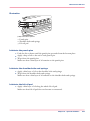
The paper module contains a control panel next to the upper paper tray. The control
panel consists of 4 sections that correspond with the 4 paper trays. Each section displays
the current filling level of the corresponding paper tray. Furthermore, the control panel
indicates whether the media in the paper tray is assigned or not. The following table describes the various parts of the control panel.
Chapter 3 - Overview of the system components
35
The paper module
The parts of the control panel#
Number
Description
1
The LEDs indicate the current amount of sheets in the corresponding paper tray. Each lit-up LED indicates the presence of about 100
sheets (based on media of 80 g/m2 or 20 lb bond).
2
Press the button to open the corresponding paper tray. You can
only open 1 paper tray at a time.
3
When the check mark is green, the media in the paper tray is defined.
The system knows which media is in the paper tray.
4
When the arrows are red, the media in the paper tray is not defined.
The system does not know which media is in the paper tray. The
'Trays' view on the operator panel indicates that no media is assigned
to the paper tray.
5
The 'Not assigned' button. This button applies to the paper tray
where you just put the media.
You can press the 'Not assigned' button when you load a new media
type into a paper tray without defining this media type on the operator panel first. Then the printer cannot accidentally use the media
in this paper tray before the media is correctly defined on the operator panel. You can define the media type in the 'Trays' view on the
operator panel later (see ‘Assign the media to a paper tray’ on page
168).
Note:
Make sure that the paper tray is open when you press the
'Not assigned' button.
36
Chapter 3 - Overview of the system components
The dual paper tray (optional)
The dual paper tray (optional)
Introduction
Task for operators, key operators
The dual paper tray is an optional high-capacity paper tray. You can use a dual paper tray
instead of a standard bulk tray. A standard bulk tray can contain up to 1,700 sheets. A
dual paper tray can contain 2 stacks of paper (A4 LEF or Letter LEF). The total capacity
of a dual paper tray is about 3,400 sheets.
The following procedures describe how to replace the bulk trays with dual paper trays,
and the other way round.
Note:
Do not fill the dual paper tray above the maximum levels as indicated on the 2 stickers
inside the paper tray. Put the left-hand paper stack fully against the left edge. Put the
right-hand paper stack fully against the right edge.
Before you begin
Make sure that the paper tray you want to replace is empty.
Note:
When the dual paper trays are installed for the first time, a number of adjustments are
required. Therefore, Océ service technicians will do the initial installation.
Caution:
The bulk trays and the dual paper trays are heavy. Always remove and install the bulk
trays and the dual paper trays with 2 persons.
How to remove a bulk tray or dual paper tray
1. On the operator panel, select the 'Trays' view.
2. Press the paper tray where you want to install the dual paper tray.
3. Press 'Open'.
The rails on both sides of the paper tray contain 2 orange stickers with an arrow.
4. Slide the paper tray out until you see the first orange sticker.
A spring-lock is situated next to the sticker.
Chapter 3 - Overview of the system components
37
The dual paper tray (optional)
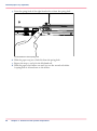
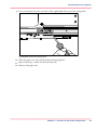
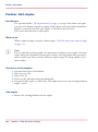
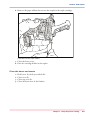
5. Press the spring-lock of the right-hand rail to release the spring-lock.
[17] Release the first spring-lock
6. Slide the paper tray just a little bit from the spring-lock.
7. Repeat the steps 3 and 4 for the left-hand rail.
8. Slide the paper tray further out until you see the second red sticker.
A spring-lock is situated next to the sticker.
38
Chapter 3 - Overview of the system components
The dual paper tray (optional)
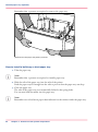
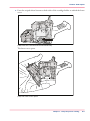
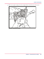
9. Put a screwdriver into the rear hole of the right-hand rail to press the spring-lock.
[18] Release the second spring-lock
10. Slide the paper tray just a little bit from the spring-lock.
11. Repeat the steps 7 and 8 for the left-hand rail.
12. Remove the paper tray.
Chapter 3 - Overview of the system components
39
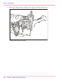
The dual paper tray (optional)
Remember that 2 persons are required to remove the paper tray.
[19] Remove the paper tray with 2 persons
How to install a bulk tray or dual paper tray
1. Take the paper tray.
Note:
Remember that 2 persons are required to install a paper tray.
2. Slide the rails of the paper tray into the rails of the printer.
Push the paper tray far enough into the rails to prevent that the paper tray can drop.
3. Close the paper tray.
The rails of the paper tray are automatically locked in the spring-locks.
You can now load the media into the paper tray.
Note:
Remember not to load more paper than indicated on the stickers inside the paper tray.
40
Chapter 3 - Overview of the system components
Chapter 4
Work with the operator
panel
The dashboard
Introduction
The dashboard
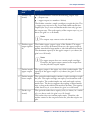
Introduction
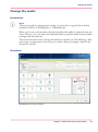
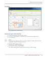
The dashboard is the upper blue part of the operator panel. The dashboard is always visible,
irrespective of the current view (see ‘The operator panel’ on page 27). The dashboard gives
the following feedback.
■ The status of the system
■ The current process
■ Instructions for the operator
■ The status of the supplies
■ The status of the external finisher, if applicable
Illustration
The following illustration shows the dashboard while the machine is busy. The vertical
status bar is green. No action is required.
[20] The dashboard - No action is required
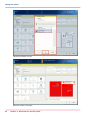
The following illustration shows the dashboard while the machine is busy. The vertical
status bar is orange. Next to the status bar, the dashboard displays a message that indicates
which action is required soon.
[21] The dashboard - Action is required soon
The parts of the dashboard
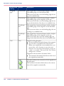
The dashboard#
42
Number
Function
1
Display the status of the machine, for example 'Initialising...',
'Printing...' or 'Printing will stop...'. Each status message can
have a sub-message with additional information.
Chapter 4 - Work with the operator panel
The dashboard
Number
Function
2
Display the file name of the current job (for document printing)
or current stream (for stream printing). Furthermore, the
progress of the current job is displayed.
For document printing, the counter can display the following
information.
■ Set X of Y
■ Sheet X of Y or Sheet X.
X represents the current status of the print job. Y represents the
total number of sets or sheets of a print job.
When the sorting method for a job is set to 'By set', and a set
contains at least 40 pages, then the dashboard displays the set
count (Set X of Y).
When the sorting method for a job is set to 'By page', or when
you print stream jobs, then the dashboard only displays a sheet
count.
3
Display the action that you must do now or soon. The colours
of the vertical status bar at the left-hand side match the colours
of the operator attention light (see ‘The operator attention light’
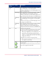
on page 30). When the colour is orange or red, a message indicates the required action.
Orange means that action is required soon. How long before
an upcoming action the operator panel starts to display the
message depends on the defined warning time (see ‘Change the
warning time’ on page 186).
Red means that action is required now.
Note:
The operator panel can only display one message at a
time. When there are more messages, the operator
panel displays the first required or most important
message.
4
■
■
■
Display the status of the external finisher, if applicable.
Display the status of the staple cartridges (see ‘Check the
status of the staple cartridges’ on page 173).
Display the status of the toner reservoir (see ‘Check the status
of the toner reservoir’ on page 172).
Chapter 4 - Work with the operator panel
43
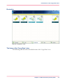
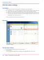
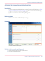
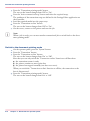
Introduction to the 'Schedule' view
The Schedule view
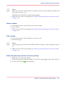
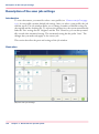
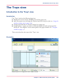
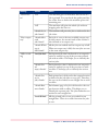
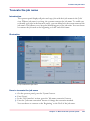
Introduction to the 'Schedule' view
Introduction
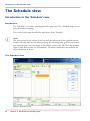
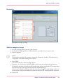
The 'Schedule' is your daily planning board for print jobs. The 'Schedule' helps you to
keep the machine running.
This section shows and describes the main parts of the 'Schedule'.
Note:
The descriptions of the colours of the bars and the indication of the required amount
of sheets are only valid for document printing. For streaming jobs , all the bars remain
grey until the paper trays are empty or the output locations are full. Then the machine
stops and the bars become red. Furthermore, the media toolbar does not indicate the
required amount of sheets.
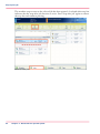
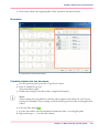
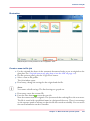
The 'Schedule' view
[22] The 'Schedule' view
44
Chapter 4 - Work with the operator panel
Introduction to the 'Schedule' view
1. The jobs pane
The jobs pane shows the jobs on a timeline. The width of the job corresponds to the
(remaining) print time. A vertical line separates the jobs. The vertical line moves to the
left as the printing of a job progresses.
An icon and the job name represent a job. The icon indicates the state of the job, for example printing .
Furthermore, the icon indicates the stop moments of the machine. For example, when
the setting 'Confirm start of job' in the workflow profiles (see ‘Work with the workflow
profiles’ on page 179) is set to 'On' or when you use the 'Stop after job' function.
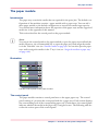
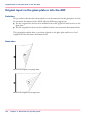
2. The 'Required media' pane
The 'Required media' pane displays the media that are required for each scheduled job.
For each required media, the media properties are displayed (see ‘Introduction to the 'Trays'
view’ on page 165). The bars show the availability of the media. The bars can have the
following colours.
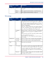
The colours of the bars#
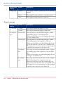
Colour of the bar
Description
Green
The required media is available.
Orange
The media is required in the future, but not available then. For
example because the paper trays do not contain sufficient sheets
of the required media.
Yellow
The system cannot determine the exact number of sheets that
is available in the paper trays.
Red
The media is required now, but not available. The job can only
start when you load the required media.
When you print small jobs, the bars for these jobs may not be completely visible. To
prevent that you do not see the status of these small jobs, the operator panel can show
the following images.
Note:
When you set the zoom control (5) to a shorter time-scale, in most cases the operator
panel will display bars for these small jobs.
The possible display of small jobs#
Image
Description
Green. The required media is available.
Chapter 4 - Work with the operator panel
45
Introduction to the 'Schedule' view
Image
Description
Orange. The media is required in the future, but not available
then. For example because the paper trays do not contain sufficient sheets of the required media.
Red. The media is required now, but not available. The job can
only start when you load the required media.
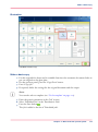
3. The media toolbar
The media toolbar displays the following information for the media that is selected in
the 'Required media' pane. Furthermore, the media type toolbar contains the 'Load'
button to load and assign the required media.
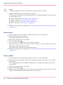
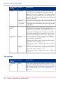
The icons in the media toolbar#
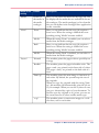
Icon
Description
The list of 'Required media' shows the required media for the
scheduled jobs. When the paper module indicator is completely
grey, this means that not one of the required media is available
in the paper trays.
The list of 'Required media' shows the required media for the
scheduled jobs. When a paper tray is highlighted in green, the
highlighted paper tray contains a media that is required by one
of the scheduled jobs.
The list of 'Required media' shows the required media for the
scheduled jobs. When a paper tray is highlighted in blue, the
highlighted paper tray contains the media that is also highlighted
in blue in the list of 'Required media'.
A job can require more sheets of a certain media than is available
in the paper trays. This indicator indicates the number of extra
needed sheets. When no horizontal lines are visible, the paper
trays contain enough sheets to print the job.
A job can require more sheets of a certain media than is available
in the paper trays. This indicator indicates the number of extra
needed sheets. Each horizontal line indicates the need for about
100 sheets. Here, about 800 extra sheets are required.
Note:
The indicator also indicates the number of sheets that
is required when a media is not available in the paper
trays.
46
Chapter 4 - Work with the operator panel
Introduction to the 'Schedule' view
Icon
Description
A job can require more sheets of a certain media than is available
in the paper trays. This indicator indicates the number of extra
needed sheets. Each horizontal line indicates the need for about
100 sheets. Here, more than 1,500 extra sheets are required.
4. The output locations pane
The output locations pane displays the output locations that are required for the scheduled
jobs. The bars show the availability of the output locations. The bars can have the following
colours.
The colours of the bars#
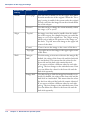
Colour of the bar
Description
Green
The output location is required and available.
Orange
The output location is required in the future, but not available
then. For example because the output location will be full soon.
Red
The output location is required now, but not available. For example because the output location is full.
5. The zoom control
The zoom control enables you to adjust the time scale that is visible in the 'Schedule'.
When you press the zoom button, a drop-down list appears. Then you can select the desired time scale.
Chapter 4 - Work with the operator panel
47
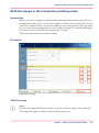
Load the media
Load the media
Introduction
This section describes how to load the media into a paper tray.
When you load the media via the 'Load' button in the 'Schedule', the paper tray is automatically assigned to the correct media.
When you load and assign the media via the 'Assign' button in the 'Trays' view, you must
assign the paper tray to the loaded media manually.
When no external finisher is connected to the machine, you must put all the media types
face down and header down into the paper trays. Cyclic media is straight collated. The
tabs of tab sheets must be at the right-hand side. When an external finisher is connected
to the machine, it is possible that you must put the media into the paper trays in a different
way. Refer to the documentation of the external finisher for more information about how
to place the media.
When to do
■
■
■
■
The 'Schedule' displays a red bar next to a required media. The red bar indicates that
a scheduled job now requires a media that is not available in the paper trays.
The 'Schedule' displays an orange bar next to a required media. The orange bar indicates that, in the future, a scheduled job requires a media that is not or not sufficiently
available in the paper trays.
The current job requires more of the same media than currently loaded in the paper
trays. You can add more of the required media into another paper tray.
You already want to load and assign media that are required for the next job (work
ahead).
Note:
Always put the stack of media at the left-hand side of the paper guides inside the paper
trays, as indicated on the sticker inside the paper trays.
Note:
When the finisher is the output location of your jobs, then you must put the oriented
media face down, header up into the paper tray.
48
Chapter 4 - Work with the operator panel
Load the media
Illustration
[32] The sticker inside the paper trays indicates how to load the media
Load the media
1. Put a small stack of the media into the paper tray.
2. Pinch the green handle of the right-hand guide and push the guide against the edge of
the media.
3. Turn the green knob to adjust the front guide and the rear guide.
4. Put the rest of the media on top of the small stack.
Note:
When you want to assign the media later you must press the 'Not assigned' button (see‘The
paper module’ on page 35), as indicated at the right-hand side of the sticker.
Chapter 4 - Work with the operator panel
49
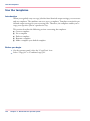
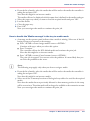
Stop a print job
Stop a print job
Introduction
When the machine is printing a job, you can stop the machine at the following moments.
■ Stop after a set
■ Stop after a page
■ Stop after a job.
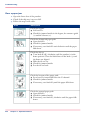
The following table gives an overview of the stop behaviour of the machine. The procedures in this section describe how to stop the machine via the operator panel.
Note:
You can also interrupt a job by ejecting a stack of sheets from the stacker. When you
press the eject button next to the stacker door 1 time, the stacker ejects the stack when
a set is ready. When you press the eject button 2 times, the stacker ejects the stack as
soon as possible.
The stop behaviour of the machine
When does the machine stop#
When
Then
You press the Hold key
1 time
The machine stops when a set of the active print job is ready. It depends on
the set size and the moment you press the
key, when the machine will stop. For example, when you have a large set of 1,000
pages and you press the key after the first
page, the printing will continue for a
couple of minutes.
You press the Hold key
2 times
The machine stops as soon as possible
(after a page, in most cases within 30
seconds).
You press the 'Stop after job' button in
the toolbar of the 'Jobs' view
50
Chapter 4 - Work with the operator panel
The machine stops when the selected job
is ready.
The 'Jobs' view displays a horizontal red
and white stop bar below the selected job.
The 'Schedule' view displays a vertical
stop bar behind the selected job.
Stop a print job
When
Then
The '<html>Check first set</html>' setting in a 'Workflow profile' is 'On' (see
‘Work with the workflow profiles’ on page
179) and this setting is also enabled in the
job
The machine stops each time the first set
of a print job is ready. You can check the
first set before you continue the print job.
The 'Confirm start of job' setting in a
'Workflow profile' is 'On'
The machine stops each time at the start
of a job. You must start each job manually.
Note:
When you print streaming jobs or jobs that consist of 1 large set, you must always
press the Hold key 2 times to stop the machine as soon as possible.
Stop after a set
1. Press the Hold key 1 time.
The red LED of the Hold key starts to blink.
The machine stops when a set of the active print job
is ready.
Stop after a page
1. Press the Hold key 2 times.
The red LED of the Hold key starts to blink.
The machine stops as soon as possible.
Note:
The memory of the machine can contain up to 50 pages. Therefore, it is possible that
the machine prints more than a set before the machine stops.
Stop after a job
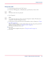
1. In the list of 'Scheduled jobs' in the 'Jobs' view, press the job after which the machine
must stop.
2. Press 'Stop after job'.
Chapter 4 - Work with the operator panel
51
Stop a print job
The machine stops as soon as the selected job has been printed. A red and white stop bar
indicates that the stop-after-job function is active. Press 'Stop after job' again to remove
the stop bar and continue printing.
[33] Stop after job
52
Chapter 4 - Work with the operator panel
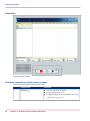
Introduction to the 'Jobs' view
The Jobs view
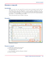
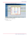
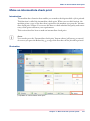
Introduction to the 'Jobs' view
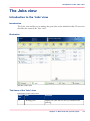
Introduction
The 'Jobs' view enables you to manage the print jobs on the machine locally. This section
describes the items of the 'Jobs' view.
Illustration
[34] The 'Jobs' view
The items of the 'Jobs' view
Description of the 'Jobs' view#
Number
Item
Function
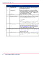
1
'Waiting jobs'
Display the jobs that are not yet scheduled for
printing.
Chapter 4 - Work with the operator panel
53
Introduction to the 'Jobs' view
Number
Item
Function
2
'Scheduled jobs'
Display the active print job
are scheduled for printing.
3
'Printed jobs'
Display the jobs that were printed successfully.
The system only moves the printed jobs to the list
of 'Printed jobs' when the setting 'Job history' in
the Settings Editor is enabled.
4
'Scan jobs'
Display the jobs that are scanned.
5
'Properties' button
Check or change the properties of a job. The button is only enabled when you select 1 job.
and the jobs that
Note:
You can also press a job 2 times to check
or change the properties of that job.
54
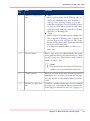
6
'To top' button
Give priority to a scheduled job. The job is printed
when the active print job is ready (see ‘Give priority to a scheduled job’ on page 61). The button
is only enabled when you select 1 job.
7
'Stop after job' button
Stop the machine after a selected job (see ‘Stop a
print job’ on page 50). The button is only enabled
when you select 1 job.
8
'Delete' button
Delete the selected job(s) (see ‘Delete a job’ on page
62). The button is enabled when you select 1 or
more jobs.
Chapter 4 - Work with the operator panel
Introduction to the 'Jobs' view
Number
Item
Function
9
'Move' or 'Copy' button
■
■
10
'Proof' button
'Move'
Move a job from the list of 'Waiting jobs' to
the list of 'Scheduled jobs' (see ‘Schedule a
waiting job for printing’ on page 57), or the
other way round (see ‘Print a scheduled job later’
on page 64).The 'Move' button is only active
when you work with jobs in the list of 'Scheduled jobs' or 'Waiting jobs'.
'Copy'
Send a copy of a job that has been printed before to the list of 'Waiting jobs' to reprint the
job (see ‘Reprint a job’ on page 59). The 'Copy'
button is only active when you work with jobs
in the list of 'Printed jobs'.
The button is enabled when you select 1 or
more jobs.
Print 1 copy of a job to check whether the result
of the print job meets your expectation (see ‘Make
a proof’ on page 66). The button is only enabled
when you select 1 job.
Note:
The proof print is not subtracted from the
number of sets you defined for this job.
11
'Ticket' button
Print an overview of the main job settings and job
parameters (see ‘Print the job parameters’ on page
68). The button is only enabled when you select
1 job.
12
'Bundle' or 'Split' button
Combine a number of jobs into 1 job, for example
to create a set of documents that are required for
a meeting (see ‘Bundle and split jobs’ on page 70).
Chapter 4 - Work with the operator panel
55
Introduction to the 'Jobs' view
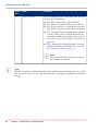
Number
Item
Function
13
'Select' button
Select a number of jobs at the same time. You can
use one of the following.
■ Use 'All' to select all the jobs in the list.
■ Use 'None' to deselect all the jobs in the list.
■ Use 'Invert selection' to turn the selected jobs
into deselected jobs, and the other way round.
■ Use '<html>Jobs with available media</html>'
to select all the jobs for which the media are
currently available in the paper trays (see ‘Print
all the jobs for which the media are available’ on
page 74).
■ Use '<html>Jobs with label</html>' to select
all the jobs with a certain label (see ‘Print the
jobs that have a label’ on page 75).
Note:
The active print job is only selected when
the machine is on hold.
Note:
Whether a button is enabled depends on the number of selected jobs, the state of the
jobs and the list that is active. Not all of the above settings are available for streaming
jobs .
56
Chapter 4 - Work with the operator panel
Schedule a waiting job for printing
The print function
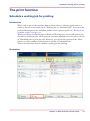
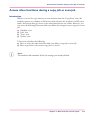
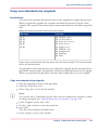
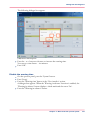
Schedule a waiting job for printing
Introduction
When a job is sent to the machine (from a printer driver, a software application or a
scanner), the job arrives in the list of 'Waiting jobs' or 'Scheduled jobs'. You can set the
preferred destination in the workflow profiles on the operator panel (see ‘Work with the
workflow profiles’ on page 179).
When you choose to send the jobs to the list of 'Waiting jobs' to have full control over
the order in which the jobs will be printed, you must manually move the jobs to the list
of 'Scheduled jobs' to print the jobs. However, you can use the options of the 'Select'
button to send a number of jobs directly to the list of 'Scheduled jobs'.
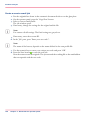
This section describes how to schedule a waiting job for printing.
Illustration
[35] Schedule a waiting job for printing
Chapter 4 - Work with the operator panel
57
Schedule a waiting job for printing
Schedule a waiting job for printing
1. On the operator panel, press the 'Jobs' button.
2. In the list of 'Waiting jobs', press the job you want to print.
Note:
You can use the options of the 'Select' button to select a number of waiting jobs at once.
You can also press a number of jobs one by one. To undo the multiple selection and only
select 1 job, you must press the desired job for 2 seconds. Then only the desired job is
selected.
3. Press 'Move'.
The selected job is moved to the bottom of the list of 'Scheduled jobs'.
58
Chapter 4 - Work with the operator panel
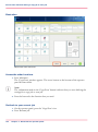
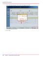
Reprint a job
Reprint a job
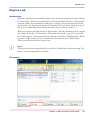
Introduction
When the machine has successfully printed a job, the system can move the job to the list
of 'Printed jobs'. This list can temporarily store the printed jobs. The list of 'Printed jobs'
is not an archive. It is intended to enable you to reprint a job quicker and easier. Each
printed job of day X remains in the list of 'Printed jobs' for 24 hours. Then the jobs of
day X are automatically removed from the system on 00.00 hours of day X + 1.
When you reprint a job from the list of 'Printed jobs', the job is not moved. The original
job remains in the list of 'Printed jobs'. The system only sends a copy of the job to the
list of 'Waiting jobs'. You cannot send a job directly to the list of 'Scheduled jobs'. When
you do no longer need a job, you can delete the job from the list of 'Printed jobs'.
This section describes how to reprint a job.
Note:
The system only moves the printed jobs to the list of 'Printed jobs' when the setting 'Job
history' in the Settings Editor is enabled.
Illustration
[36] Reprint a job
Chapter 4 - Work with the operator panel
59
Reprint a job
Reprint a job
1. On the operator panel, press the 'Jobs' button.
2. In the list of 'Printed jobs', press the job you want to reprint.
3. Press 'Copy'.
The system sends a copy of the job to the list of 'Waiting jobs'.
4. Press the job in the list of 'Waiting jobs'.
5. Press 'Properties' to change the settings, for example the number of prints.
6. Press 'Move'.
The job is moved to the bottom of the list of 'Scheduled jobs'.
60
Chapter 4 - Work with the operator panel
Give priority to a scheduled job
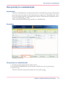
Give priority to a scheduled job
Introduction
The list of 'Scheduled jobs' contains the jobs that are scheduled for printing. The machine
prints the jobs in the order in which the jobs arrive in the list of 'Scheduled jobs'. However, you can give priority to an urgent job in the list. Then that job is printed as soon
as the active print job is ready.
This section describes how to give priority to a scheduled job.
Illustration
[37] Move a job to top
Give priority to a scheduled job
1. On the operator panel, press the 'Jobs' button.
2. In the list of 'Scheduled jobs', press the job to which you want to give priority.
3. Press 'To top'.
The job is moved to the position below the active print job .
Chapter 4 - Work with the operator panel
61
Delete a job
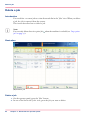
Delete a job
Introduction
You can delete 1 or more jobs at a time from each list in the 'Jobs' view. When you delete
a job, the job is removed from the system.
This section describes how to delete a job.
Note:
You can only delete the active print job
job’ on page 50).
when the machine is on hold (see ‘Stop a print
Illustration
[38] Delete a job
Delete a job
1. On the operator panel, press the 'Jobs' button.
2. In one of the lists in the 'Jobs' view, press the job you want to delete.
62
Chapter 4 - Work with the operator panel
Delete a job
Note:
You can use the options of the 'Select' button to select a number of jobs at once. You can
also press a number of jobs one by one. To undo the multiple selection and only select
1 job, you must press the desired job for 2 seconds. Then only the desired job is selected.
3. Press 'Delete'.
A dialogue box will ask you to confirm that you really want to delete the selected job.
4. Press 'Yes' to remove the selected job from the list and from the system.
Chapter 4 - Work with the operator panel
63
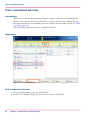
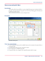
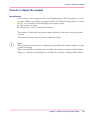
Print a scheduled job later
Print a scheduled job later
Introduction
When a job is scheduled for printing, the job is present in the list of 'Scheduled jobs'.
However, for various reasons you can choose to print a job later. For example because
the required media are not available or because you first want to make a proof (see ‘Make
a proof’ on page 66).
This section describes how to print a scheduled job later.
Illustration
[39] Print a scheduled job later
Print a scheduled job later
1. On the operator panel, press the 'Jobs' button.
2. In the list of 'Scheduled jobs', press the job you want to print later.
64
Chapter 4 - Work with the operator panel
Print a scheduled job later
Note:
From the drop-down list of the 'Select' button, you can also select 'All', '<html>Jobs with
available media</html>' or '<html>Jobs with label</html>' to select more jobs at once,
except the active print job . To move the active print job , you must first press the
Hold key . You can also press a number of jobs one by one. To undo the multiple selection and only select 1 job, you must press the desired job for 2 seconds. Then only the
desired job is selected.
3. Press 'Move'.
The job is moved to the bottom of the list of 'Waiting jobs'.
Chapter 4 - Work with the operator panel
65
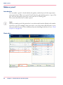
Make a proof
Make a proof
Introduction
You can make a proof to check whether the quality and the layout of the output meet
your expectations. When you use the 'Proof' function, the machine prints 1 copy of the
job. You can only make a proof for a job in the list of 'Waiting jobs'.
This section describes how to make a proof.
Note:
When you make a proof, the printed set is not subtracted from the defined total number
of sets for a job. For example, when you need 10 sets, the printer will still print 10 sets
after you made the proof. This is different from the checking of the first set (see ‘Check
the first set’ on page 80).
Illustration
[40] Print a proof
66
Chapter 4 - Work with the operator panel
Make a proof
Make a proof
1. On the operator panel, press the 'Jobs' button.
2. In the list of 'Waiting jobs', press the job of which you want to make a proof.
Note:
You can select more than 1 job at a time.
3. Press 'Proof'.
A copy of the job goes to the bottom of the list of 'Scheduled jobs'.
The original job remains in the list of 'Waiting jobs'.
You can recognise a proof by the magnifying glass on the job icon .
Chapter 4 - Work with the operator panel
67
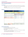
Print the job parameters
Print the job parameters
Introduction
You can print an overview of the job settings and the job parameters (the so-called job
ticket) before you print a job. The overview can show you for example which media the
job requires.
This section describes how to print the overview of the job parameters.
Illustration
[41] Print the job parameters
Print the job parameters
1. On the operator panel, press the 'Jobs' button.
2. Press the job of which you want to print the job parameters.
You can only select 1 job at a time.
3. Press 'Ticket'.
The job is sent to the bottom of the list of 'Scheduled jobs'. The job may not be immediately visible in the list of 'Scheduled jobs'.
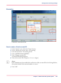
You can recognise the job by the prefix @_ in front of the job name.
68
Chapter 4 - Work with the operator panel
Print the job parameters
The printed job ticket is sent to the system output (see‘The output locations’ on page 32).
Chapter 4 - Work with the operator panel
69
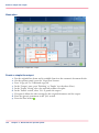
Bundle and split jobs
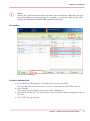
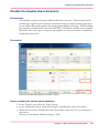
Bundle and split jobs
Introduction
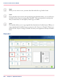
Create a bundled job
If you want to combine 2 or more documents into 1 set, for example to prepare a meeting,
you can bundle jobs that are present in the list of 'Waiting jobs'. The original jobs are
removed from the list. The bundled job appears at the bottom of the list of 'Waiting
jobs'. The system automatically creates a name for the bundled job that is based on the
name of the first job in the bundle.
The number of copies for the bundled job is initially set to 1. You can handle the bundled
job like any other job. For example, you can move the job to the list of 'Scheduled jobs',
edit the job, delete the job or make a proof.
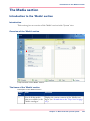
Edit a bundled job
You can define the following properties for a bundled job.
■ The order of the jobs in the bundle
■ The number of sets
■ Whether you want to check the first set of the bundled job.
Note:
This section describes the above in separate procedures. However, you can always access
the 'Properties' window and change 1 or more properties at the same time. You cannot
change the properties of the individual jobs in the bundle. To do this, you must first
split the bundled job. Then you can change the properties of each job.
Split a bundled job
In the list of 'Waiting jobs', you can split a bundled job into the original jobs. The system
removes the bundled job. The individual jobs are added at the end of the list of 'Waiting
jobs'.
This section describes how to create, edit and split a bundled job.
General information
■
■
■
■
70
When you print a bundled job, the machine prints the number of copies that you indicated for the bundled job. The number of copies of the original jobs is ignored.
When you stop a job after a set (see ‘Stop a print job’ on page 50), the printing stops
after 1 copy of the complete bundle.
The jobs in a bundle are accounted separately under the account ID of the original
jobs.
You cannot combine a bundled job with another bundled job.
Chapter 4 - Work with the operator panel
Bundle and split jobs
Note:
All the jobs in the bundle must have the same output destination. Otherwise, the operator panel displays a warning message. To continue, you must first split the job, then
change the individual jobs and finally bundle the jobs again.
Illustration
[42] Create a bundled job
Create a bundled job
1. From the list of 'Waiting jobs', select the jobs you want to bundle.
You can select the jobs one by one, or use one of the options of the 'Select' button.
2. Press 'Bundle'.
The operator panel displays an overview of the bundled job.
3. If required, use the keys 'Up' and 'Down' in the 'Job order' field to change the order of
the jobs.
4. Press 'OK' to accept the job.
Chapter 4 - Work with the operator panel
71
Bundle and split jobs
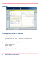
Illustration
[43] Edit a bundled job
Change the order of the jobs in a bundled job
1.
2.
3.
4.
5.
Select the bundled job.
Press 'Properties'.
In the 'Job order' field, select the job you want to move.
Use the keys 'Up' and 'Down' to move the job to the required position.
Press 'OK'.
Change the number of sets for a bundled job
1. Select the bundled job.
2. Press 'Properties'.
3. Press the 'Number of sets' button.
A numerical keyboard appears.
4. Use the numerical buttons to enter the desired number of sets.
72
Chapter 4 - Work with the operator panel
Bundle and split jobs
Note:
Press the arrow button <- to correct the previous entry or press 'Cancel' to close the numerical keyboard without saving the changes.
5. Press 'OK'.
The numerical keyboard disappears.
6. Press 'OK'.
Check the first set of a bundled job
1. Select the bundled job.
2. Press 'Properties'.
3. Press 'Check first set' when the button states 'Off'.
The text changes from 'Off' to 'On'. A check mark indicates that the checking of the first
set is enabled. The machine will automatically go on hold after the first set was printed.
4. Press 'OK'.
Split a bundled job
1. Select a bundled job in the list of 'Waiting jobs'.
2. Press 'Split'.
The system adds the original jobs to the end of the list of 'Waiting jobs'.
Chapter 4 - Work with the operator panel
73
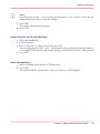
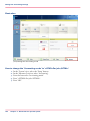
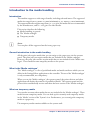
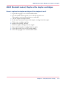
Print all the jobs for which the media are available
Print all the jobs for which the media are available
Introduction
You can select and print the jobs for which the media are currently available in the paper
trays all at once. This improves the productivity because a regular change of media types
is not required. This section describes how to select the jobs for which the media are
present in the paper trays.
Illustration
[44] Select the jobs for which the media are available
Print the jobs for which the media are available
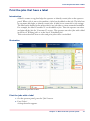
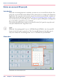
1. On the operator panel, press the 'Jobs' button.
2. Press the 'Select' button.
3. Press '<html>Jobs with available media</html>'.
The system selects and highlights the jobs for which the required media are available in
the paper trays.
4. Press 'Move'.
The selected jobs are moved to the bottom of the list of 'Scheduled jobs'.
74
Chapter 4 - Work with the operator panel
Print the jobs that have a label
Print the jobs that have a label
Introduction
A label is a name or tag that helps the operator to identify certain jobs on the operator
panel. When a job is sent to the machine, a label can be added to that job. The label can
be any name that helps to identify certain jobs. A label is not connected to job settings.
The label can be defined in the printer driver, in a job ticket or via an automated workflow.
For example, the label ‘Customer X’ can be added to jobs. Then the operator can select
and print all the jobs for 'Customer X' at once. The operator can select jobs with a label
in the list of 'Waiting jobs' or in the list of 'Scheduled jobs'.
This section describes how to select and print jobs with a certain label.
Illustration
[45] Print the jobs with a label
Print the jobs with a label
1. On the operator panel, press the 'Jobs' button.
2. Press 'Select'.
A drop-down list appears.
Chapter 4 - Work with the operator panel
75
Print the jobs that have a label
3. Press '<html>Jobs with label</html>'.
A pop-up window with an overview of the available labels appears.
4. Press the desired label.
Note:
You can select more than 1 label.
5. Press 'OK'.
The pop-up window disappears.
6. Press 'Move'.
The selected jobs are moved to the bottom of the list of 'Scheduled jobs'.
76
Chapter 4 - Work with the operator panel
Change the number of sets
Check and change the job properties
Change the number of sets
Introduction
Note:
This section applies to changing the settings of a print job or copy job that is already
available in the list of 'Waiting jobs' or 'Scheduled jobs'.
When a job is sent to the machine, the desired number of sets will be indicated. However,
you can change the number of sets on the operator panel.
This section describes how to change the number of sets for a specific job.
Note:
You can enter any value between 1 and 65,000 for all jobs except the active print job .
To change the number of sets for the active print job , you must first press the Hold
key 1 time. Then you can change the number of sets. You cannot define a lower value
than the number of sets that has already been printed.
Chapter 4 - Work with the operator panel
77
Change the number of sets
Illustration
[46] Change the number of sets
Change the number of sets
1. On the operator panel, press the 'Jobs' button.
2. In the list of 'Waiting jobs' or 'Scheduled jobs', press the job you want to edit.
3. Press 'Properties'.
Note:
You can also press the job 2 times to access the 'Properties' window. This function is
comparable to double-clicking with a mouse.
4. Press the 'Number of sets' button.
A numerical keyboard appears.
5. Use the numerical buttons to enter the desired number of sets.
Note:
Press the arrow button <- to correct the previous entry or press 'Cancel' to close the numerical keyboard without saving the changes.
78
Chapter 4 - Work with the operator panel
Change the number of sets
6. Press 'OK'.
The numerical keyboard disappears.
7. Press 'OK'.
Chapter 4 - Work with the operator panel
79
Check the first set
Check the first set
Introduction
Note:
This section applies to changing the settings of a print job or copy job that is already
available in the list of 'Waiting jobs' or 'Scheduled jobs'.
You can indicate that you want to print 1 set of a job first to check the print quality.
When the print quality meets your expectations, you can continue the job.
You can use 1 of the following methods to indicate that you want to check the first set.
■ Use a workflow profile where 'Check first set' is enabled (see ‘Work with the workflow
profiles’ on page 179. Then the machine always prints 1 set before the entire job is
printed. The machine goes on hold after 1 set is printed.
■ Enable the function 'Check first set' in the 'Properties' option of the 'Jobs' view for a
specific job only. However, this only works when the setting 'Check first set' in the
workflow profiles is set to '<html>As in job</html>' (see ‘Work with the workflow
profiles’ on page 179).
This section describes how to indicate that you want to check the first set for a specific
job only.
Note:
When you use the function 'Check first set', the printed set is subtracted from the indicated total number of sets for a job. For example, when you need 10 sets, the machine
will print the first set and then stop. When you continue the job, the 9 remaining sets
are printed. This is different from the making of a proof (see ‘Make a proof’ on page 66).
80
Chapter 4 - Work with the operator panel
Check the first set
Illustration
[47] Check the first set
Enable the checking of the first set
Note:
You cannot enable the checking of the first set for the active print job
list of 'Printed jobs'.
or a job in the
1. On the operator panel, press the 'Jobs' button.
2. In the list of 'Waiting jobs' or 'Scheduled jobs', press the job you want to edit.
3. Press 'Properties'.
Note:
You can also press the job 2 times to access the 'Properties' window. This function is
comparable to double-clicking with a mouse.
4. Press 'Check first set' when the button states 'Off'.
The text changes from 'Off' to 'On'. A check mark indicates that the checking of the first
set is enabled. The machine will automatically go on hold after the first set is printed.
Chapter 4 - Work with the operator panel
81
Check the first set
5. Press 'OK'.
82
Chapter 4 - Work with the operator panel
Change the media
Change the media
Introduction
Note:
This section applies to changing the settings of a print job or copy job that is already
available in the list of 'Waiting jobs' or 'Scheduled jobs'.
When a job is sent to the machine, the desired media will usually be indicated in the job
ticket. However, you can replace the indicated media by another media from the media
catalogue with the same size.
This section describes how to change the media for a specific job. The following 3 illustrations give an impression of the screens you will see when you change a media in the
'Properties' window.
Illustration
[48] Select the media to replace
Chapter 4 - Work with the operator panel
83
Change the media
[49] Select another media
[50] The media is changed
84
Chapter 4 - Work with the operator panel
Change the media
Change the media
1. On the operator panel, press the 'Jobs' button.
2. In the list of 'Waiting jobs' or 'Scheduled jobs', press the job you want to edit.
Note:
You cannot select the active print job.
3. Press 'Properties'.
Note:
You can also press the job 2 times to access the 'Properties' window. This function is
comparable to double-clicking with a mouse.
4. In the preview section, press the button of the media you want to change (see ‘Change
the media’ on page 83).
When the Media catalogue contains media with the same size, the operator panel will
display a list of these media (see ‘Change the media’ on page 83).
5. Select the new media you want to use.
6. Press 'OK'.
The new media is assigned to the job (see ‘Change the media’ on page 83).
7. Press 'OK'.
Chapter 4 - Work with the operator panel
85
Change the output location
Change the output location
Introduction
Note:
This section applies to changing the settings of a print job or copy job that is already
available in the list of 'Waiting jobs' or 'Scheduled jobs'.
In the Settings Editor, you can set the default output location for print jobs. However,
you can change the output location on the operator panel for each job individually. Depending on the configuration of your system, you can select one of the following output
locations.
■ Finisher upper output
■ 'Finisher'
■ 'Stacker'
■ Stacker/stapler
■ Stacker/stapler upper output
■ 'External finisher'.
This section describes how to select another output location for a specific job.
Note:
There must be a match between the selected output location and the job requirements.
For example, when a job does not require staples, you can select any output location.
When a job requires 1 or 2 staples, you can only select the output locations that can
staple the jobs, for example Finisher or External finisher because the Stacker cannot
staple the jobs. When you make a combination that is not possible, the operator panel
displays an error message.
86
Chapter 4 - Work with the operator panel
Change the output location
Illustration
[51] Change the output location
Change the output location
1. On the operator panel, press the 'Jobs' button.
2. In the list of 'Waiting jobs' or 'Scheduled jobs', press the job you want to edit.
3. Press 'Properties'.
Note:
You can also press the job 2 times to access the 'Properties' window. This function is
comparable to double-clicking with a mouse.
4. Press the 'Output location' button.
A drop-down list with the available output locations appears.
5. Select the desired output location.
The button displays the selected output location.
Chapter 4 - Work with the operator panel
87
Change the number of staples
Change the number of staples
Introduction
Note:
This section applies to changing the settings of a print job or copy job that is already
available in the list of 'Waiting jobs' or 'Scheduled jobs'.
When a job is sent to the machine, a desired number of staples for that job can be indicated. However, you can change the number of staples on the operator panel.
This section describes how to change the number of staples for a specific job.
Illustration
[52] Change the number of staples
Change the number of staples
1. On the operator panel, press the 'Jobs' button.
2. In the list of 'Waiting jobs' or 'Scheduled jobs', press the job you want to edit.
3. Press 'Properties'.
88
Chapter 4 - Work with the operator panel
Change the number of staples
Note:
You can also press the job 2 times to access the 'Properties' window. This function is
comparable to double-clicking with a mouse.
4. Press the 'Staples' button.
5. Select the desired number of staples.
The 'Staples' button displays the selected number of staples.
Chapter 4 - Work with the operator panel
89
Change the sorting method
Change the sorting method
Introduction
Note:
This section applies to changing the settings of a print job or copy job that is already
available in the list of 'Waiting jobs' or 'Scheduled jobs'.
When a job is sent to the machine, the sorting method is usually defined by the Settings
Editor. However, you can change the sorting method on the operator panel. You can select
one of the following.
■ 'By set'
The pages will be sorted in the order 123, 123, 123.
■ 'By page'.
The pages will be sorted in the order 111, 222, 333.
This section describes how to change the sorting method for a specific job.
Illustration
[53] Change the sorting method
90
Chapter 4 - Work with the operator panel
Change the sorting method
Change the sorting method
1. On the operator panel, press the 'Jobs' button.
2. In the list of 'Waiting jobs' or 'Scheduled jobs', press the job you want to edit.
3. Press 'Properties'.
Note:
You can also press the job 2 times to access the 'Properties' window. This function is
comparable to double-clicking with a mouse.
4. Press 'Finishing'.
5. Press the 'Sort' button.
The two sorting methods appear.
6. Select the desired sorting method.
The 'Sort' button displays the selected sorting method.
Chapter 4 - Work with the operator panel
91
Change the type of offset stacking
Change the type of offset stacking
Introduction
Note:
This section applies to changing the settings of a print job or copy job that is already
available in the list of 'Waiting jobs' or 'Scheduled jobs'.
You can use the function 'Offset stacking' to create a visible distinction between sets or
jobs in an output location. When 'Offset stacking' is enabled, each set or job will be
stacked with an offset compared to the previous set or job. You can set the default type
of offset stacking in the workflow profile on the operator panel (see ‘Work with the
workflow profiles’ on page 179). The following table describes when you can change the
type of offset stacking for specific jobs.
Possibility to change the type of offset stacking per job#
When
Then
The type of offset stacking is set to
'<html>Sets (as in job)</html>'
You can change the type of offset stacking
per job via the 'Properties' window in the
'Jobs' view.
The type of offset stacking is set to
'<html>Jobs</html>', '<html>Sets (always)</html>', '<html>Banners</html>'
or '<html>Off</html>'
You cannot change the type of offset
stacking per job. The 'Properties' window
displays the system value.
This section describes the following.
■ The values you can select in the 'Properties' window when '<html>Sets (as in
job)</html>' is set in the workflow profile
■ How to change the type of offset stacking per job via the 'Properties' window.
Types of offset stacking in the 'Properties' window
When '<html>Sets (as in job)</html>' is set in the workflow profile, then you can select
one of the following types of offset stacking.
Available types of offset stacking in the 'Properties' window#
92
When
Then
You select 'Each set'
All the printed sets are sent to the output
location with an offset between the sets.
You select 'Off'
All the printed sets are sent to the output
location in one straight stack.
Chapter 4 - Work with the operator panel
Change the type of offset stacking
Illustration
[54] Change the type of offset stacking
Change the type of offset stacking
1. On the operator panel, press the 'Jobs' button.
2. In the list of 'Waiting jobs' or 'Scheduled jobs', press the job you want to edit.
3. Press 'Properties'.
Note:
You can also press the job 2 times to access the 'Properties' window. This function is
comparable to double-clicking with a mouse.
4. Press the 'Offset stacking' button.
The two types of offset stacking appear.
5. Press the desired type of offset stacking.
The 'Offset stacking' button displays the selected type of offset stacking.
Chapter 4 - Work with the operator panel
93
Shift the margin or image
Shift the margin or image
Introduction
Note:
This section applies to changing the settings of a print job or copy job that is already
available in the list of 'Waiting jobs' or 'Scheduled jobs'.
When you use for example pre-printed media with marked locations for specific text, a
misalignment of the text can occur. For example, an address is not exactly placed in the
centre of an address field, or an account number is not exactly placed in the appropriate
box. To correct these misalignments, you can shift the image. You can shift the images
on the front side and back side horizontally and vertically.
When you want to shift the margin or image of an existing job, you can use the following
methods.
Available methods to shift the image in the 'Properties' window#
When
Then
You use the margin
shift
Your image will shift from the binding edge.
■ The image for left oriented documents will shift from
the left-hand margin. When the sheet is 2-sided, the
image at the back side will shift from the right-hand
margin.
■ The image for top oriented documents will shift from
the top margin. When the sheet is 2-sided, the image
at the back side will shift from the bottom margin
You use the image shift
The image will shift from the bottom left corner.
This section describes how to shift the margin or image of an existing job.
Note:
When you want to hide punch holes, use the setting 'Margin erase' (see ‘Output settings’
on page 112).
94
Chapter 4 - Work with the operator panel
Shift the margin or image
Illustration
[55] Shift the margin or image
Shift the margin or image
1. On the operator panel, press the 'Jobs' button.
2. In the list of 'Waiting jobs' or 'Scheduled jobs', press the job you want to edit.
3. Press 'Properties'.
Note:
You can also press the job 2 times to access the 'Properties' window. This function is
comparable to double-clicking with a mouse.
4. Press 'Shift'.
The two methods to shift the image appear.
5. Press the - or + buttons to shift the image on the front side or back side of the sheet.
By default, the values of the front side and the back side are interlocked. This means that
the values for the front side and the back side remain identical.
If you want to define a different value for each side, press . The icon changes to the unlocked status. Now you can define the values for the front side and the back side separately.
6. Press 'OK'.
Chapter 4 - Work with the operator panel
95
Introduction to the Copy/Scan view
The Copy/Scan view
Introduction to the Copy/Scan view
Introduction
The 'Copy/Scan' view is the starting point for all your copy jobs and scan jobs. The
'Copy/Scan' view contains buttons that give access to the creation of copy jobs and scan
jobs.
■ Select 'Copy job' to copy paper originals that do not consist of several parts (subsets)
which require different settings
■ Select 'Combined copy job' to copy paper originals that consist of several subsets which
require individual settings
■ Select a scan profile when the scan function is enabled. The scan function enables you
to create a digital document (a file) from paper originals. The system can send this
file to a scan server or to an email address, for example. The names of the scan profiles
that the 'Copy/Scan' view displays derive from the names that are set in the scan profiles
file (.csv file). The scan profiles file is located on the controller. You can retrieve the
file from the Settings Editor application on the controller. The scan profiles file allows
you to define a large number of scan related settings (see ‘The scan profiles file’ on page
141).
This section describes the items of the 'Copy/Scan' view.
96
Chapter 4 - Work with the operator panel
Introduction to the Copy/Scan view
Illustration
[56] The 'Copy/Scan' view
The items of the 'Copy/Scan' view
The following table describes the default items of the 'Copy/Scan' view.
Chapter 4 - Work with the operator panel
97
Introduction to the Copy/Scan view
The items of the 'Copy/Scan' view#
98
Item
Description
1
'Copy job'
Use the 'Copy job' button to copy a document
without subsets. The settings you define apply to
the whole job (see ‘Make a basic copy’ on page 118).
When you press the 'Copy job' button the copy
job window opens. There you can define the settings for both the paper original and the output.
In the job window, you can also select a template
to carry out a copy job (see ‘Use the templates’ on
page 124) or add subsets. Use the 'Subsets' button
if you want to add subsets (see ‘Combine subsets
into one document ’ on page 120).
The window opens with the settings defined in
the default template by the operator.
2
'Combined copy job'
Use the 'Combined copy job' button to create one
document from different subsets (see ‘Combine
subsets into one document ’ on page 120).
When you press the 'Combined copy job' button
the combined copy job window opens. There you
can define the settings for the first subset. In the
job window, you can also select a template to carry
out a copy job.
The window opens with the settings defined in
the default template by the operator.
3
'Scan to file' *
Use the 'Scan to file' button to scan a paper original and create a digital document. The system automatically sends the resulting file to a scan server
(see ‘Introduction to the scan function’ on page 135).
When you press the 'Scan to file' button the job
window opens. There you can define the settings
for both the original and the file.
4
'Scan to email' *
Use the 'Scan to email' button to scan a paper
original and create a digital document. The system
automatically sends the resulting file as an attachment to an email address (see ‘Introduction to the
scan function’ on page 135).
When you press the 'Scan to email' button the job
window opens. There you can define the settings
for both the original and the file.
Chapter 4 - Work with the operator panel
Introduction to the Copy/Scan view
5
Item
Description
'Last used'
Use the 'Last used' button to use the settings of
the previous copy job for your new copy job.
When you press the 'Last used' button the job
window opens. This window displays all the settings of the previous copy job.
Note:
The 'Last used' button does not apply to
scan jobs or combined copy jobs.
Note:
* The names of the buttons depend on the names that are defined in the scan profiles
file.
Chapter 4 - Work with the operator panel
99
Original input on the glass plate or into the ADF
Original input on the glass plate or into the ADF
Definition
The procedures that describe the methods to scan documents from the glass plate or from
the automatic document feeder (ADF) offer the following suggestions.
■ Put the original face down and in readable form in the upper left-hand corner on the
glass plate.
■ Put the originals face down and in readable form into the automatic document feeder.
This paragraph explains how to position originals on the glass plate and how to feed
originals into the automatic document feeder.
Illustration
[57] Portrait original, long edge feed
[58] Portrait original, short edge feed
100
Chapter 4 - Work with the operator panel
Original input on the glass plate or into the ADF
[59] Landscape original, short edge feed
Portrait original, long edge feed
■
■
■
Hold the original in front of you in readable position.
Turn the original over the long edge.
Place the original into the automatic document feeder or on the glass plate.
Note:
You get the maximum productivity when you scan A4 originals in long edge feed direction.
Portrait original, short edge feed
■
■
■
■
Hold the original in front of you in readable position.
Rotate the original 90 degrees anti-clockwise.
Turn the original over the long edge.
Place it into the automatic document feeder or on the glass plate.
Landscape original, short edge feed
■
■
■
Hold the original in front of you in readable position.
Turn the original over the short edge.
Place it into the automatic document feeder or on the glass plate.
Note:
If you scan an original which long edge size is greater than the vertical glass plate size,
you must always use a short edge feed. Long edge feed does not fit into the automatic
document feeder.
Chapter 4 - Work with the operator panel
101
Original input on the glass plate or into the ADF
Glass plate position
Glass plate position#
Component
Function
Scan a portrait document in vertical position on the glass plate.
[60] Glass plate scan
portrait
Scan a landscape document in horizontal position on the glass
plate.
[61] Glass plate scan
landscape
Note:
If you scan an original which long edge size is greater than the vertical glass plate size,
you must always scan the original in horizontal position.
102
Chapter 4 - Work with the operator panel
Access other functions during a copy job or scan job
Access other functions during a copy job or scan job
Introduction
When you access the copy function or scan function from the 'Copy/Scan' view, the
machine opens a new window in full screen mode. Because the window is in full screen
mode, the buttons that give access to the other functions are not visible. However, you
can access the following functions while you define the settings for your copy job or scan
job.
■ 'Schedule' view
■ 'Jobs' view
■ 'Trays' view
■ 'System' view.
This section describes the following.
■ How to access the other functions while you define a copy job or scan job
■ How to get back to the current copy job or scan job
Note:
The machine will remember all the job settings you already defined.
Chapter 4 - Work with the operator panel
103
Access other functions during a copy job or scan job
Illustration
[62] Access other functions
Access the other functions
1. Press 'Minimise'.
The 'Copy/Scan' window appears. The access buttons at the bottom of the operator
panel become visible.
Note:
The exclamation mark in the 'Copy/Scan' button indicates that you were defining the
settings for a copy job or scan job.
2. Press the button for the function that you need.
Get back to your current job
1. On the operator panel, press the 'Copy/Scan' view.
2. Press 'Resume job'.
104
Chapter 4 - Work with the operator panel
Access other functions during a copy job or scan job
You will get back to the window where you were defining the settings for a copy job or
scan job.
Chapter 4 - Work with the operator panel
105
The zoom behaviour
The zoom behaviour
Introduction
When you carry out a copy job or scan job, you can use the 'Zoom' function to reduce
or enlarge an image, for example:
■ Copy an A4 original on an A3 sheet. The system enlarges the image
■ Copy an A3 original on an A4 sheet. The system reduces the image
■ Copy an A4 original with a small illustration on an A4 sheet, and at the same time
enlarge the illustration.
By factory default, the zoom function is set to 'Fit to page'. This makes sure that no information is lost. To change the zoom factor manually, press the - and + buttons of the
'Zoom' function in the job window. When you use non-standard size originals, you must
use the glass plate. The scanner can not automatically detect the size of the originals on
the glass plate. Therefore, you must select the original size manually.
The zoom function for originals in the automatic document feeder is different from the
zoom function for originals on the glass plate.
Zoom behaviour#
Original
Starting point of the zoom function
Automatic document feeder
Centre
Glass plate
Upper left-hand corner
This section describes the characteristics of the zoom function when you use the automatic
document feeder or the glass plate.
Note:
The zoom function works identical for both copy jobs and scan jobs.
Scan from the automatic document feeder and use the zoom function
The following table shows the zoom behaviour of the machine when the originals are
scanned from the automatic document feeder. The focus is on the centre of the original.
106
Chapter 4 - Work with the operator panel
The zoom behaviour
Scan from the automatic document feeder using the zoom function#
Illustration
Description
The original is placed face down and in readable form into
the automatic document feeder.
The centre of the original is a fixed point and is used as the
origin of the image.
Result of a scan with a 100% zoom factor.
Result of a scan with a 50% zoom factor.
Note:
The centre of the image is fixed.
Result of a scan with a 200% zoom factor.
Note:
The centre of the image is fixed.
Scan from the glass plate and use the zoom function
The following table shows the zoom behaviour of the machine when the originals are
scanned from the glass plate. The focus is on the upper right-hand corner of the original
(upper left-hand corner of the glass plate).
Scan from the glass plate using the zoom function#
Illustration
Description
The original is placed face down and in readable form in
the upper left-hand corner on the glass plate.
The upper left-hand corner of the glass plate is a fixed point
and is used as the origin of the image.
Chapter 4 - Work with the operator panel
107
The zoom behaviour
Illustration
Description
Result on paper of a scan with a 100% zoom factor.
Result on paper of a scan with a 50% zoom factor.
Note:
The upper right-hand corner of the image is fixed.
Result on paper of a scan with a 200% zoom factor.
Note:
The upper right-hand corner of the image is fixed.
108
Chapter 4 - Work with the operator panel
Description of the copy job settings
The copy function
Description of the copy job settings
Introduction
When you make a copy, you must always define the following.
■ The characteristics of the paper originals
■ The characteristics of the output
■ Generic settings that apply to the whole job, like the required number of sets.
When you access the copy function from the 'Copy/Scan' view, the job window displays
the settings you can define. To increase the productivity, the system automatically links
a number of settings for the 'Original' and the 'Output'. However, you can always manually overrule these automated settings. The automated settings have the prefix 'Auto'.
This section describes the parts and settings of the job window.
Illustration
[71] The job window for copy jobs
Chapter 4 - Work with the operator panel
109
Description of the copy job settings
The parts of the job window
#
Number
Pane
Description
1
'Original'
The 'Original' pane shows the settings you
can define for the paper originals
2
'Output'
The 'Output' pane shows the settings you can
define for the output
3
'Job'
The 'Job' pane shows the generic settings you
can define for the whole job
4
Preview
The preview displays the settings you defined
for the output. Furthermore, this pane gives
access to the templates
5
Action buttons
The action buttons indicate the actions you
can carry out.
'Original' settings
#
110
Name of the
setting
Values
Description
'1- or 2-sided'
'1-sided'
Only 1 side of an original contains an image.
'2-sided'
Both sides of an original contain an image.
Chapter 4 - Work with the operator panel
Description of the copy job settings
Name of the
setting
Values
Description
'Original
type'
'Portrait left'
The original has a vertical format (height > width).
The binding edge is at the left-hand side.
When you turn a sheet over the binding edge the image is in readable form.
'Portrait top'
The original has a vertical format (height > width).
The binding edge of the original is at the top.
When you turn a sheet over the binding edge the image on the back side of the sheet is in readable form.
'Landscape
left'
The original has a horizontal format (width > height).
The binding edge of the original is at the left-hand
side.
When you turn a sheet over the binding edge, the text
or image is in readable form.
'Landscape
top'
The original has a horizontal format (width > height).
The binding edge of the original is at the top.
When you turn a sheet over the binding edge, the
image on the back side of the sheet is in readable form.
'Size'
Original on the glass plate:
■ You must indicate the media format of the original.
■ You can select a predefined size from the list.
When your original has a non-standard size, you
can use the - and + buttons to enter the exact
measures. You can enter the measures in steps of
1 mm / 0.01 inches. The text of the 'Size' button
changes into 'Custom'.
'Size'
Originals in the automatic document feeder:
■ The automatic document feeder detects the size of
the originals automatically.
You must indicate the orientation of the original on
the glass plate.
The automatic document feeder detects the orientation of the originals automatically.
Chapter 4 - Work with the operator panel
111
Description of the copy job settings
Name of the
setting
Values
Description
'Image type'
'Mixed'
The original contains a combination of text and illustrations.
'Photo'
The original contains mainly or only illustrations.
'Text'
The original contains mainly or only text.
Name of the
setting
Values
Description
'1- or 2-sided'
'1-sided'
The output contains an image on 1 side.
'2-sided'
The output contains an image on both sides.
'Document
type'
'Portrait left'
The output has a vertical format (height > width).
The binding edge is at the left-hand side.
When you turn a sheet over the binding edge the image is in readable form.
'Portrait top'
The output has a vertical format (height > width).
The binding edge of the original is at the top.
When you turn a sheet over the binding edge the image on the back side of the sheet is in readable form.
This means that every back side of a 2-sided original
is upside down compared to the front side.
'Landscape
left'
The output has a horizontal format (width > height).
The binding edge of the original is at the left-hand
side.
When you turn a sheet over the binding edge, the text
or image is in readable form.
'Landscape
top'
The output has a horizontal format (width > height).
The binding edge of the original is at the top.
When you turn a sheet over the binding edge, the
image on the back side of the sheet is in readable form.
This means that every back side of a 2-sided original
is upside down compared to the front side.
'Output' settings
#
112
Chapter 4 - Work with the operator panel
Description of the copy job settings
Name of the
setting
Values
Description
'Media'
Names of
the media in
the media
catalogue
Here you can select the media for the copy job. The
list displays all the media that are available in the media catalogue. The media catalogue is a list of media
that you can define in the Settings Editor application
on the controller.
'Cover'
'Front'
Here you can indicate that the copy job requires a
front cover. When the setting is enabled the corresponding setting 'Media' becomes enabled.
'Media'
When the setting 'Front' is enabled, you can select a
media from the media catalogue.
'Back'
Here you can indicate that the copy job requires a
back cover. When the setting is enabled the corresponding setting 'Media' becomes enabled.
'Media'
When the setting 'Back' is enabled, you can select a
media from the media catalogue.
'Normal'
The machine prints the pages with no special layout
settings.
'Booklet'
The machine prints the pages in booklet order. The
pages 1 and 4 are printed on the front side of a sheet.
The pages 2 and 3 are printed on the back side of a
sheet.
'Same up'
The machine prints the same image 2 times next to
each other. By default, the system keeps the size of
the originals.
When you copy A4 originals with the setting 'Same
up', the machine will automatically print the job on
A3, for example. When you cut the A3 sheets in two,
you get 2 identical A4 copies of your document. To
decrease your A4 originals to A5 prints, you can use
the zoom function or select another media type.
'2-up'
The machine prints 2 consecutive images on 1 side
of a sheet, next to each other.
'Layout'
Chapter 4 - Work with the operator panel
113
Description of the copy job settings
Name of the
setting
Values
Description
'Zoom'
'Fit to page'
You can select a media size for the output that differs
from the media size of the original. When the 'Fit to
page' setting is enabled, the system scales the original
in such a way that the image fits on the selected media
size of the output.
'Percent'
Use this setting to change the zoom manually within
the range 25% to 400%.
'Top left'
An image on a sheet may be smaller than the media
size of the output, for example because you scaled the
image to 70% of its original size. The 'Align' setting
allows you to indicate the position of the image on
the sheet. 'Top left' moves the image to the upper left
corner of the sheet.
'Centre'
'Centre' moves the image to the centre of the sheet.
'Top right'
'Top right' moves the image to the upper right corner
of the sheet.
'Margin
shift'
Use this setting to increase or decrease the margin. By
default, the values of the front side and the back side
are interlocked. This means that the values for the
front side and the back side remain identical.
If you want to define a different value for each side,
press . The icon changes to the unlocked status. Now
you can define the values for the front side and the
back side separately.
'Image shift'
Use this setting to shift the image horizontally or vertically. By default, the values of the front side and the
back side are interlocked. This means that the values
for the front side and the back side remain identical.
If you want to define a different value for each side,
press . The icon changes to the unlocked status. Now
you can define the values for the front side and the
back side separately.
'Align'
'Shift'
114
Chapter 4 - Work with the operator panel
Description of the copy job settings
Name of the
setting
Values
Description
'Sort'
'By page'
The output is sorted by page.
'By set'
The output is sorted by set.
'Each set'
Each set that gets to an output location will be shifted
on top of the previous set.
'Offset stacking'
Note:
This setting is only available when in the
workflow profile offset stacking is set to
'<html>Sets (as in job)</html>'.
'Output location'
'Off'
All the sets or jobs that get to an output location will
be stacked in one straight pile.
Names of
the available
output locations
Select the output location for the copy job. Depending
on the settings for your copy job, the machine automatically suggests the preferred output location for
your job. However, you can manually overrule this
suggestion.
Chapter 4 - Work with the operator panel
115
Description of the copy job settings
Name of the
setting
Values
Description
'Staples'
'None', 1
and 2
Here you can define the required number of staples.
The staple setting is only available when an output
location is available.
Note:
If your machine has the optional puncher, the
name of the setting changes into 'Finishing'.
Then you can also enable or disable the punch
function.
'Margin
erase'
'Exposure'
'Subset start'
116
Margins of a document sometimes contain notes or
punch holes, for example. The machine allows you to
hide these elements on the copy. With the + and buttons of the 'Margin erase' setting you can define
how much margin of the original you want to erase.
You can enter a value up to 100 mm / 3.94 inches.
'Dark'
You can adjust the settings for light areas and dark
areas on the print separately.
When an area on the output is dark grey but must be
black, then select a value of 1 to 3.
When the area must be lighter, then select a value of
-1 to -3.
'Light'
When an area on the output is light grey but must be
white, then select a value of 1 to 3.
When the area must be darker, then select a value of
-1 to -3.
'On previous
sheet'
When you carry out a combined copy job the situation
can occur that the back side of the last sheet of a subset
is empty. When you select 'On previous sheet' the
system will skip the empty page. The next subset will
start on the empty back side.
'On new
sheet'
When you select 'On new sheet' the system will keep
the empty page. The next subset will start on a new
sheet.
Chapter 4 - Work with the operator panel
Description of the copy job settings
'Job' settings
#
Name of the
setting
Values
Description
'Job name'
By default, all copy jobs are named 'Copy job' with a
sequence number. To identify your copy job more
easily in the list of waiting jobs or scheduled jobs, you
can change the name of the copy job. When you press
the 'Job name' button a keyboard appears.
'Number of
sets'
Use this setting to define the number of copies. You
can enter a value from 1 - 65,000. The default value
is 1.
'Check first
set'
'On'
The machine stops the print job after the first set.
Now you can check if the first set is OK. When the
first set is OK you can resume the print job.
Note:
This setting is only available when in the
workflow profile Check first set is set to
'<html>As in job</html>'.
'Destination'
'Account ID'
'Off'
The machine prints the whole job. The machine does
not stop after the first set.
'Scheduled
jobs'
Add the copy job to the list of 'Scheduled jobs' in the
'Jobs' view.
'Waiting
jobs'
Add the copy job to the list or 'Waiting jobs' in the
'Jobs' view.
Enter the account ID for the current job. The account
ID function is only available when the accounting
function on the controller is enabled.
Chapter 4 - Work with the operator panel
117
Make a basic copy
Make a basic copy
Introduction
You can use the copy function of the machine to carry out all kinds of copy jobs. Copy
jobs can vary from basic one-to-one copy jobs without subsets to more advanced jobs
with subsets (see ‘Combine subsets into one document ’ on page 120). When you make a
basic copy, all the settings that you make apply to the whole document.
This section describes how to make a basic copy that the machine prints as soon as possible.
Before you begin
■
■
■
■
■
Remove all staples from your originals.
Remove the paper clips.
Make sure that the originals in the automatic document feeder have the same size.
Make sure that the automatic document feeder does not contain more than 75 sheets
(80 g/m² or 20 lb bond).
Make sure that the originals are not curled.
Note:
The machine contains a function called double-sheet detection. This function checks
whether the originals in the automatic document feeder are separated and scanned one
by one. When sheets stick together, the operator panel displays a warning:
'<HTML>Check the originals: a double sheet is detected.</HTML>'. By default, this
function is enabled. However, when you copy or scan paste-up originals, it can be convenient to disable the double-sheet detection (see ‘Disable the double-sheet detection’ on
page 197).
118
Chapter 4 - Work with the operator panel
Make a basic copy
Illustration
[76] Make a basic copy
Make a basic copy
1. Put the originals face down and in readable form into the automatic document feeder or
put one original on the glass plate.
2. On the operator panel, press the 'Copy/Scan' button.
3. Press 'Copy job'.
4. If required, define the settings for the original document and the output.
Note:
You can also select a template (see ‘Use the templates’ on page 124).
5. Enter the generic parameters in the 'Job' section.
6. Select 'Scheduled jobs' in the 'Destination' field.
7. Press the Start button .
The job is added to the list of 'Scheduled jobs'.
Chapter 4 - Work with the operator panel
119
Combine subsets into one document
Combine subsets into one document
Introduction
You can use the copy function of the machine to carry out all kinds of copy jobs. You
can carry out a basic copy job where all the settings you make apply to the whole document,
for example (see ‘Make a basic copy’ on page 118). However, the creation of documents
like brochures or reports can be more laborious. The following situations can occur, for
example.
■ You want to copy a document that consists of several parts - called subsets - that differ
from each other and require individual settings
■ You want to combine different documents into one document
■ You want to include tab sheets and inserts in your document to separate chapters, for
example.
When you include tab sheets or inserts, you must define each tab sheet or insert as a
separate subset. Make sure that you have defined tab sheets and inserts in the Media
catalogue. You can find the Media catalogue in the Settings Editor application on the
controller.
Different subsets are subsets that have a mix of 1-sided and 2-sided pages, or require different media, for example. When you copy these types of documents, you must define
the settings for each subset individually. The 'Combined copy job' function allows you
to combine subsets into one document. The preview pane shows a full overview of the
subsets you defined.
This section describes the following.
■ Combine subsets into one document.
Furthermore, this sections describes the actions you can carry out from the View
subsets pane.
■ Add a subset.
■ Insert a subset.
■ Delete a subset.
■ Edit a subset.
Before you begin
1. Divide your document into subsets.
2. Put the first subset into the automatic document feeder or on the glass plate.
Note:
When you use the automatic document feeder, the size of the originals must be one of
the supported standard sizes.
120
Chapter 4 - Work with the operator panel
Combine subsets into one document
3. If necessary, adjust the original guides of the automatic document feeder.
Illustration
[77] Example of the preview pane
Combine subsets into one document
1. On the operator panel, press the 'Copy/Scan' button.
2. Press 'Combined copy job'.
The job window opens.
3. Define the settings for the first subset (original and output).
Note:
Some settings that you define for the first subset apply to the whole job, the 'Layout'
settings, for example. These settings are fixed and are greyed out after scanning the first
subset.
4. Press the Start button .
5. Put the next subset into the automatic document feeder or on the glass plate.
6. Repeat the steps 3 - 5 for all other subsets.
Chapter 4 - Work with the operator panel
121
Combine subsets into one document
Note:
A number indicates the order in which the subsets have been scanned.
7. When all subsets have been scanned, press 'Ready'.
A full overview of all the scanned subsets appears in the right-hand pane. If required, you
can still adapt the job:
■ Add another subset (see ‘Add a subset’ on page 122)
■ Insert a subset (see ‘Insert a subset’ on page 122)
■ Delete a subset (see ‘Delete a subset’ on page 123)
■ Edit a subset (see ‘Edit a subset’ on page 123).
8. When the job is OK, start printing (see ‘Define the general parameters and start printing’
on page 123).
Add a subset
1. Put the subset into the automatic document feeder or on the glass plate.
2. In the preview pane, press 'Add'.
The settings pane becomes available.
3. Define the settings for the new subset.
4. Press the Start button .
The new subset is added to the end of the list of subsets.
5. Repeat the steps 3 and 4 if you want to add more subsets, or press 'Ready' when all the
additional subsets have been scanned.
The full overview of all the scanned subsets appears.
6. When the job is OK, start printing (see ‘Define the general parameters and start printing’
on page 123).
Insert a subset
1. Put the subset into the automatic document feeder or on the glass plate.
2. In the preview pane, press the subset below the position where you want to insert a subset.
3. Press 'Insert'.
The settings pane becomes available. Furthermore, an empty line appears above the selected subset.
4. Define the settings for the new subset.
5. Press the Start button .
6. Repeat the steps 4 and 5 if you want to insert more subsets after the new subset, or press
'Ready' when all the additional subsets have been scanned.
122
Chapter 4 - Work with the operator panel
Combine subsets into one document
Note:
If you want to insert another subset at another position, you must first press 'Ready' and
then repeat the steps 1 to 5.
The full overview of all the scanned subsets appears.
7. When the job is OK, start printing (see ‘Define the general parameters and start printing’
on page 123).
Delete a subset
1. In the preview pane, press the subset you want to delete.
2. Press 'Delete'.
3. When the job is OK, start printing (see ‘Define the general parameters and start printing’
on page 123).
Edit a subset
1. In the preview pane, select the subset you want to edit.
2. Edit the settings.
Note:
The settings you can edit become available. All the settings you cannot change are greyed
out.
3. When the job is OK, start printing (see ‘Define the general parameters and start printing’
on page 123).
Define the general parameters and start printing
1. When the job is OK, press 'Ready'.
2. Define the parameters, like the number of sets. These values apply to the whole copy job.
3. Press the Start button to start printing.
Chapter 4 - Work with the operator panel
123
Use the templates
Use the templates
Introduction
When you regularly carry out copy jobs that have identical output settings, you can create
and use templates. The machine can store up to 5templates. Templates contain the predefined output settings for your recurring jobs. Therefore, the templates enable you to
copy your repetitive jobs in a productive way.
This section describes the following actions concerning the templates.
■ Create a template
■ Use a template
■ Delete a template
■ Rename a template
■ Make a template your default template.
Before you begin
1. On the operator panel, select the 'Copy/Scan' view.
2. Select 'Copy job' or 'Combined copy job'.
124
Chapter 4 - Work with the operator panel
Use the templates
Illustration
[78] The templates view
Create and save a template
1.
2.
3.
4.
Define the output settings you want to save into a template.
Press the 'Templates' icon.
Select the template called 'Current' and hold the button for 2 seconds.
Select 'Save'
The system saves the template. The system also assigns a new name 'Custom' with a
number that is not yet in use.
Use a template
1. Press the 'Templates' icon.
The operator panel displays all the available templates.
2. Select the template you want to use.
Chapter 4 - Work with the operator panel
125
Use the templates
Note:
If you hold the button for 2 seconds, a list of options appears. Now you can still press
'Select' to use the current template.
Delete a template
1. Press the 'Templates' icon.
The operator panel displays all the available templates.
2. Press the template you want to delete and hold the button for 2 seconds.
A list of options appears.
3. Select 'Delete'.
Note:
You cannot delete the default template and the current template. To remove a default
template, you must first make another template your default template.
Rename a template
1. Press the 'Templates' icon.
The operator panel displays all the available templates.
2. Press the template you want to rename en hold the button for 2 seconds.
A list of options appears.
3. Select 'Rename'.
A keyboard appears.
4. Enter a new name.
5. Press 'OK'.
Make a template your default template
1. Press the 'Templates' icon.
The operator panel displays all the available templates.
2. Press the template you want to make your default template and hold the button for 2
seconds.
A list of options appears.
3. Select '<html>Make default</html>'.
The new default template gets a check mark.
126
Chapter 4 - Work with the operator panel
Rename a copy job
Rename a copy job
Introduction
When you carry out a new copy job, the system creates an automatic name for the job.
The default name 'Copy Job' followed by a sequence number is displayed in the 'Job
name' setting of the 'Job' pane. However, you can rename the copy job into a name of
your choice. This name helps you to recognise the job in the list of '<html>Scheduled
jobs</html>' or '<html>Waiting jobs</html>'.
This section describes how to rename a copy job.
Illustration
[79] Rename a copy job
Rename a copy job
1. Define the settings for your copy job.
2. Press 'Job name' in the 'Job' pane.
A keyboard appears.
3. Press 'Backspace' until the old name is deleted.
4. Enter a new name.
Chapter 4 - Work with the operator panel
127
Rename a copy job
5. Press 'OK'.
128
Chapter 4 - Work with the operator panel
Copy non-standard size originals
Copy non-standard size originals
Introduction
You can use the automatic document feeder to copy originals in a simple and quick way.
When you place the originals, the automatic document feeder detects the size of the
originals. The automatic document feeder can automatically detect the following media
sizes.
Media sizes that the automatic document feeder supports#
ISO sizes
■
■
■
■
■
A5
A4
A3
B5
B4
US sizes
■
■
■
■
■
■
■
■
■
US Std 5.5x8.5
US Gov 8x10.5
Letter Gov 8.5x10
Letter 8.5x11
Legal 8.5x14
Tabloid 11x17
Commercial
Foolscap
Folio
If more than one media fits, the user must select the desired media. The selected media
will be the default media.
The glass plate is the location where you usually place originals that the automatic document feeder cannot handle. The glass plate cannot detect the dimensions of your original.
When you copy from the glass plate, you must always define the size of your original.
Copy non-standard size originals
1. Place the original face-down on the glass plate.
2. Select the 'Copy/Scan' view.
3. Select 'Copy job' to access the job window.
Note:
You can also select 'Combined copy job' when the non-standard size original is a subset
of a larger document (see ‘Combine subsets into one document ’ on page 120).
4. In the 'Original' section, select 'Size'.
5. Use the - and + buttons to enter the media size.
6. Press 'OK'.
The 'Size' button displays the defined size.
7. In the 'Output' section, select 'Media'.
Chapter 4 - Work with the operator panel
129
Copy non-standard size originals
8. Select a media from the list and press 'OK'.
The setting 'Zoom' determines how the copy will look. When 'Fit to page' is enabled,
the original will be scaled to fit the media size of the output. When 'Fit to page' is disabled,
the original will keep the actual size.
130
Chapter 4 - Work with the operator panel
Scan now and print later
Scan now and print later
Introduction
The machine offers the possibility to scan an original document now and print the document later. This means that the copy job is sent to the list of 'Waiting jobs'. This function
is called postponed copying.
This section describes how to scan now and print later.
Illustration
[80] Select 'Waiting jobs'
Scan now and print later
1. Put the originals face down and in readable form into the automatic document feeder or
on the glass plate.
2. On the operator panel, press the 'Copy/Scan' button.
3. Press 'Copy job' or 'Combined copy job'.
4. If required, define the settings for the original document and the output.
Chapter 4 - Work with the operator panel
131
Scan now and print later
Note:
You can also select a template (see ‘Use the templates’ on page 124)
5. Enter the generic parameters in the 'Job' section.
6. Select 'Waiting jobs' in the 'Destination' field.
The default destination is defined in the workflow profile (see ‘Work with the workflow
profiles’ on page 179).
7. Press the Start button .
The job is added to the list of 'Waiting jobs'.
132
Chapter 4 - Work with the operator panel
Punch or staple the output
Punch or staple the output
Introduction
Your machine can be equipped with several finishing devices like the puncher or stacker/stapler. When your machine is equipped with one of these finishing devices, or both
devices, you can indicate the following on the operator panel:
■ The number of staples
■ Whether you want to punch the documents
The number of holes that the puncher makes depends on the die set that the puncher
contains.
This section describes how to punch or staple the output.
Note:
When you have a puncher and a stapling device installed, the required 'Output' setting
is called 'Finishing'.
When you only have a stapling device installed, the 'Output' settings is called 'Staples'.
When you only have a punching device installed, the 'Output' settings is called 'Punch'.
Chapter 4 - Work with the operator panel
133
Punch or staple the output
Illustration
[81] Punch or staple the output
Punch or staple the output
1.
2.
3.
4.
5.
6.
7.
8.
9.
134
Put the originals face down and in readable form into the automatic document feeder.
On the operator panel, press the 'Copy/Scan' button.
Press 'Copy job' or 'Combined copy job'.
In the 'Output' pane, press 'Finishing' or 'Staples' (see the above Note).
In the 'Staples' setting, select the required number of staples.
In the 'Punch' section, select 'Yes' to punch the output.
If required, define the other settings for the original document and the output.
Enter the generic parameters in the 'Job' section.
Press the Start button .
Chapter 4 - Work with the operator panel
Introduction to the scan function
The scan function
Introduction to the scan function
Definition
The scan function allows you to convert paper originals into digital documents. The
machine offers 2 types of scanning.
■ Scan to file
■ Scan to email
All the settings for these types of scan jobs are stored in a scan profiles file on the controller
(see ‘The scan profiles file’ on page 141). This file is a comma separated values file (.csv
file). The system administrator can access this file through the Controller. The system
administrator can edit the attributes of this file like the name or resolution. The .csv file
can contain both scan-to-file profiles and scan-to-email profiles. There is no difference
in format between the two types of profile. The prefix string on the mail server and in
the scan profiles file determine whether the job is a scan-to-file job or a scan-to-email job.
Most companies use more than 1 scan profile. The system administrator can create separate
scan profiles for individual customers or departments. For example, each department can
have a scan profile to archive the files or to print the files. An example of a scan profile
is 'Purchasing, 300 dpi, TIFF'.
On the operator panel, the 'Copy/Scan" view displays the available scan profiles. In most
cases, there will be both scan-to-file profiles and scan-to-email profiles. To scan a document, you simply select the required scan profile. Next, the job window opens. There
you can change a number of settings for the current scan job. However, these changes
are only valid for this job. The default settings of the scan profiles file will not change.
For all the scan jobs, the machine supports both the Adobe® Portable Document Format
(PDF) and the Tagged Image File Format (TIFF).
This section describes the principles of both scan functions.
The scan-to-file function
The scan-to-file function is a part of the scan function. Scan to file allows you to scan a
document. The machine automatically sends the resulting file to the configured scan
server. The export mechanism is normally FTP. You can retrieve the file from the scan
server. When you use a scan profile, your document is scanned with the resolution defined
in the scan profile. The generated file has the format and the location indicated in the
scan profile. You can change the scan resolution and file format on the operator panel.
Chapter 4 - Work with the operator panel
135
Introduction to the scan function
To use the scan-to-file function, the system administrator must make a number of configurations (see ‘The configuration of the scan-to-file function’ on page 137).
The scan-to-email function
The scan-to-email function is a part of the scan function. Scan to email allows you to
scan a document and attach the resulting file to an email. The email is then automatically
sent to an email address. The scan-to-email function includes user codes. A user code is
a unique number, for example a telephone number or a salary number, that is mapped
to an email address. The combination of this user code and the matching email address
is stored on an LDAP server or entered in an address list file. You need a user code to
start a scan-to-email job. The machine displays a message asking you to enter the code.
To use the scan-to-email function, the system administrator must make a number of
configurations (see ‘The configuration of the scan-to-email function’ on page 138).
Main difference between scan to file and scan to email
The main difference between scan to file and scan to email is the following. A file that is
generated with the scan-to-file function, is stored on a scan server. You can retrieve the
document from the scan server. A document that is generated with the scan-to-email
function is attached to an email message. This email message is automatically sent to a
mail server and, from that mail server, to an indicated email address. If the machine
cannot send the email message, the message with the attached file is not saved, but removed
after an indicated time.
136
Chapter 4 - Work with the operator panel
The configuration of the scan-to-file function
The configuration of the scan-to-file function
Introduction
You must configure the following items to make this scan-to-file function operational.
1. The scan server
2. The scan settings in the Settings Editor
3. The settings for the scan profiles file. This file has the format .csv.
Actions to configure the scan-to-file function
The table below shows the actions that are necessary to configure the items in the list.
Scan-to-file function#
Step
Action
1
■
■
■
2
■
■
3
■
■
Define a scan server on the network to store the scan jobs
Create an FTP account (a user name, a password and a destination directory) on the scan server
Share the destination directory under the FTP root on the scan server.
Access the scan-to-file settings and the scan server settings in the Settings
Editor.
Define the settings for the scan server .
Retrieve the scan profiles file from the Settings Editor
Define the scan profile settings in the .csv file (see ‘The scan profiles file’
on page 141).
Chapter 4 - Work with the operator panel
137
The configuration of the scan-to-email function
The configuration of the scan-to-email function
Introduction
You must configure the following items to make the scan-to-email function operational.
■ Configure the scan-to-email settings in the Settings Editor
■ Configure the mail server
■ Configure the recipient search on the LDAP server
■ If necessary, configure an address list file
■ Upload a scan profiles file (.csv file) to the Controller (see ‘The scan profiles file’ on
page 141).
The .csv file can contain both scan-to-file profiles and scan-to-email profiles. There is no
difference in format between the two types of profile. The prefix selector string described
in the table below and the application selector string in the scan profiles file decide whether
the job is a scan-to-file job or a scan-to-email job.
Note:
You must enter values for all settings described in the tables. Otherwise, the scan-toemail function will not work correctly.
Configure the mail server
Mail server settings#
138
Mail server settings
Description
Server address
The address of the mail server. You must enter one server
address. This address can be a host name of 32 characters
or an IP-address.
Default: Empty
Port number
Default: 25
User name
The user name gives you access to the server. This user
name can be any name of up to 20 characters (a-z, A-Z ,
0-9, _).
Default: Empty
Email address of the
sender
Enter the email address of the system that sends the email
message, for example your controller. You can use the
characters a-z, A-Z, 0-9, @, ., _
Do not start an email address with a number.
Default: Empty
Chapter 4 - Work with the operator panel
The configuration of the scan-to-email function
Mail server settings
Description
Prefix selector string
Identify the scan jobs that are sent to email. The prefix
separates the scan-to-email jobs from the scan-to-file jobs.
You can use up to 8 characters (a-z, A-Z , 0-9, _). The
prefix selector string must be identical to the application
selector string in the scan-to-email profiles.
Default: Email
Configure the recipient search - LDAP server
Next, you must configure the address source, the source that contains the list of user
codes and email addresses. This address source can be the LDAP server or an address list
file. When you use an LDAP server, you must check the check box 'Enabled' to enable
the 'LDAP server' and configure the settings described below.
Recipient search settings - LDAP server#
Recipient search settings - LDAP server
Description
'Port'
Default: 389
'Host name/IP address'
Enter the address of one LDAP server. This address can be
a host name of 32 characters or an IP address.
Default: Empty
'User name'
The user name gives you access to the server. This user
name can be any name of up to 20 characters (a-z, A-Z ,
0-9, _).
Default: Empty
'Password'
The password can be any word of up to 20 characters (a-z,
A-Z, 0-9, _). Each character that you enter is shown as an
*.
Default: Empty
'Search database'
Define the path to the search database. The search database
is the area in which an email address is searched. The search
database can be any data file that contains at least unique
identifiers for the users and email addresses. The search is
from top to bottom only. You must enter the top node of
the search database to enter the data in the file.
Default: Empty
'User identification'
This attribute is the field that is compared with the code
that is entered on the operator panel.
Default: Empty
Chapter 4 - Work with the operator panel
139
The configuration of the scan-to-email function
Recipient search settings - LDAP server
Description
'E-mail address attribute'
An email address is connected to a unique user identifier.
When a search is done on the server, the first email address
that is connected to the entered user identifier, is returned.
See 'Email address of the sender' above for the format requirements.
Default: Empty
Configure the recipient search - Address list file
Recipient search settings - Address list file#
Recipient search settings - Address list file
Description
When you have no LDAP server, you can use an address
list file to search for recipients. When an address list file is
available, this file is always used. You can upload and
download the address list file to the controller.
The address list file is a comma-separated values file (.csv
file). The address list file must contain a user identifier
column and an email address column. The user identifier
must be a unique number of up to 20 digits (0-9). See
'Email address of the sender' above for the format requirements of the email address.
Note:
The name of the address list file must always be
ral.csv. Other file names are not accepted. The
header of the user identifier column must always
be ruid. The header of the email address column
must always be address.
140
Chapter 4 - Work with the operator panel
The scan profiles file
The scan profiles file
Introduction
The scan profiles file (.csv file) on the controller allows you to define different scan profiles.
Each scan profile contains a combination of individual settings for a certain type of scan
job. The name of a scan profile that is used in the scan profiles file, is displayed on the
operator panel. The .csv file can contain various scan profiles, both for scan-to-file jobs
and for scan-to-email jobs. When the scan profiles file is available and configured, the
scan profiles become visible in the 'Copy/Scan' view on the operator panel. Specific names
identify the available scan profiles. To carry out a scan job you can simply select the required scan profile in the 'Copy/Scan' view.
The .csv file contains record fields. The record fields allow you to define specific settings
for each scan profile. The table below describes the record fields of a .csv file. To change
the settings of a scan profile permanently, you must first download the .csv file from the
controller through the Settings Editor application. Then you can open the file in for example Microsoft® Excel and change the settings. You can also add new scan profiles. After
you changed and saved the file, you must upload the file to the controller. The changed
file overwrites the previous file.
Note:
The scan profiles file can contain a maximum of 99 scan profiles.
Note:
For each scan job, you can change a number of scan profile settings on the operator
panel (see ‘Description of the scan job settings’ on page 148). However, these changes only
apply to the current job.
The record fields of the scan profiles file
The record fields of the scan profiles file#
Field name
(header)
Description
dispname*
Display name
Use this field to enter a name for the scan profile. The name of the
scan profile is displayed on the operator panel. The name can be
any name between 1 and 40 characters. You can use all alphanumeric
characters except <CR>, <LF>, <,> and <;>.
Chapter 4 - Work with the operator panel
141
The scan profiles file
142
Field name
(header)
Description
format*
File format
Use this field to define the format and the compression of the scan
jobs. You can enter one of the following values.
■ TIFF G31D_MH
TIFF CCITT Group 3 1D modified Huffman compressed images
■ TIFF G42D_Fax
TIFF CCITT.T6 Group 4 2D compressed images
■ PDF G31 D_MH
PDF version 1.3 with Group 3 1D modified Huffman compressed images
■ PDF G42D_Fax
PDF version 1.3 with Group 4 2D compressed images.
■ TIFF - LZW
■ PDF - LZW
ilc*
Image Logic characteristics
Use this field to define the optimal scan result for a defined purpose.
You can enter one of the following values.
■ 1
Resolution: 600 dpi. This value optimises your scan job for
printing on Copy Press systems
■ 2
Resolution: 300 dpi. This value optimises your scan job for
viewing and archiving purposes
■ 3
Resolution: 600 dpi at 85 lpi. This value optimises your scan job
for printing on for example Demandstream® systems
■ 4
Resolution: 600 dpi at 106 lpi. This value optimises your scan
job for printing on for example Demandstream® systems.
Chapter 4 - Work with the operator panel
The scan profiles file
Field name
(header)
Description
prefix*
File name prefix
Use this field to define the type of scan job, for example 'Memo',
'Archive', 'File' or 'Email'. The string can have a length of maximum
8 characters (a-z, A-Z, 0-9, _). The prefix is a fixed part of the file
name.
Note:
You can leave this field empty. However, the field name is
required.
minnr*
maxnr*
Number of digits required to identify a scan job
Use these fields to define the minimum and the maximum number
of digits the user must enter to use the scan function. The entered
digits are stored in the file name. The numeric strings can have a
length of maximum 20 digits. When both fields are 0, the system
does not ask for an input.
Note:
The 'maxnr' must be equal to or larger than the 'minnr'.
name_nr_title*
Title of the user dialogue
Use this field to define a title for the dialogue that appears when the
user must enter digits to use the scan function. The title explains to
the user which digits are required. You can enter a title of maximum
40 characters. You can use all the alphanumeric characters except
<CR>, <LF>, <,> and <;>.
Note:
You can leave this field empty. However, the field name is
required.
Chapter 4 - Work with the operator panel
143
The scan profiles file
Field name
(header)
Description
cfname*
File name feedback
Use this field to activate a dialogue that displays the file name of
your scan job. This dialogue can be useful when you do not use a
numbering system for your scan jobs. You can write down the file
name of your scan job.
The date and time in the file name are used as a reference. The operator panel displays a dialogue with the same title as for the 'Title
of the user dialogue' described above. Below the title, the name of
the scan job is displayed.
You can define the following.
■ y
Enter 'y' (yes) to show the dialogue.
■ n
Enter 'n' (no) to hide the dialogue.
subfolder
Subfolder
Use this field to define the path to a subfolder on the scan server
where the files will be stored. When this field is empty, the files will
be stored in the folder on the scan server that is configured as the
root folder.
The maximum number is 150 subfolders.
postfix
File name postfix
Use this field to add a postfix to the file name of your scan job. For
example, when the prefix is 'Email', you can add a default email
address as a postfix. The string can have a length of maximum 30
characters. You can use all the alphanumeric characters except / \ :
* " < > <CR> and <LF>. The postfix is a fixed part of the file name.
OrigOrientation
Orientation of the originals
Use this field to define the orientation and binding of the originals
in the scanner. You can define the following.
■ portrait book
■ portrait calendar
■ landscape book
■ landscape calendar
Note:
When you leave this field empty, the system uses the default
orientation and binding. You can also define the orientation
and binding on the operator panel.
144
Chapter 4 - Work with the operator panel
The scan profiles file
Field name
(header)
Description
OrigDuplex
Original 1-sided or 2-sided
Use this field to define whether the originals in the scanner are 1sided or 2-sided. You can define the following.
■ on
The originals are 2-sided
■ off
The originals are 1-sided
Note:
When you leave this field empty, the system uses the default
value. You can also define the value on the operator panel.
OrigKind
Type of the originals
Use this field to define the type of originals in the scanner. You can
define the following.
■ photo
■ text
■ auto
■ mixed
Note:
When you leave this field empty, the system uses the default
type of originals. You can also define the type of originals
on the operator panel.
OrigZoom
Zoom of the originals
Use this field to define the zoom factor for the originals in the
scanner (25%-400%).
Note:
When you leave this field empty, the value is set to 100%.
You can also define the zoom factor on the operator panel.
Chapter 4 - Work with the operator panel
145
The scan profiles file
Field name
(header)
Description
OrigFormat
Media size of the originals
Use this field to define the media size and the feed direction of the
originals in the scanner. An example of the notation is: A4 lef. You
can define the following media sizes.
■ A5
■ Statement 5.5x8.5
■ B5
■ Letter 8.5x11
■ A4
■ Foolscap
■ Folio
■ Legal 8.5x14
■ B4
■ A3
■ US Gov 8x10.5
■ Tabloid 11x17
■ Commercial
■ Letter Gov 8.5x10
■ Legal Gov 8.5x12
■ Letter 8.25x10
■ Legal 8.5x13
You can define the following feed directions.
■ sef (short-edge feed)
■ lef (long-edge feed).
Note:
When you leave the fields for the media format or the feed
direction empty, the system uses the default values. You can
also define the media format and the feed direction on the
operator panel.
146
Chapter 4 - Work with the operator panel
The scan profiles file
Field name
(header)
Description
DestFormat
Media size of the files
Use this field to define the media size of the resulting scan files. You
can select a media size from the range that is described above.
Note:
When you leave this field empty, the media size of the output is the same as the media size of the originals. You can
also define the media size of the output on the operator
panel.
Note:
All the fields marked with * are required in the scan profiles file. Some required fields
may be empty, as described in the table above, but at least the field name must be present
in the scan profiles file. All other fields are optional.
Chapter 4 - Work with the operator panel
147
Description of the scan job settings
Description of the scan job settings
Introduction
To scan a document, you must first select a scan profile (see ‘Create a scan job’ on page
154). A scan profile contains default job settings. After you select a scan profile, the job
window opens. The job window allows you to change a number of default settings for
the original and the resulting file. To increase the productivity, the system automatically
links the 'Size' settings for the 'Original' and the 'File'. However, you can always manually overrule this automated setting. The automated setting has the prefix 'Auto'. The
changes that you make only apply to the current job.
This section describes the parts and settings of the job window.
Illustration
[82] The scan job settings
148
Chapter 4 - Work with the operator panel
Description of the scan job settings
The parts of the job window
#
Number
Pane
Description
1
'Original'
The 'Original' pane shows the settings you
can define for the paper originals
2
'File'
The 'File' pane shows the settings you can
define for the output
3
'Job'
The 'Job' pane shows the generic settings you
can define for the whole job.
4
Preview
The preview displays the settings you defined
for the output.
5
Action buttons
The action buttons indicate the actions you
can carry out. The action buttons depend on
the different modes.
'Original' settings
#
Name of the
setting
Values
Description
'1- or 2-sided'
'1-sided'
Only 1 side of an original contains an image.
'2-sided'
Both sides of an original contain an image.
Chapter 4 - Work with the operator panel
149
Description of the scan job settings
Name of the
setting
Values
Description
'Original
type'
'Portrait left'
The original has a vertical format (height > width).
The binding edge is at the left-hand side.
When you turn a sheet over the binding edge the image is in readable form.
'Portrait top'
The original has a vertical format (height > width).
The binding edge of the original is at the top.
When you turn a sheet over the binding edge the image on the back side of the sheet is in readable form.
'Landscape
left'
The original has a horizontal format (width > height).
The binding edge of the original is at the left-hand
side.
When you turn a sheet over the binding edge, the text
or image is in readable form.
'Landscape
top'
The original has a horizontal format (width > height).
The binding edge of the original is at the top.
When you turn a sheet over the binding edge, the
image on the back side of the sheet is in readable form.
'Size'
Original on the glass plate:
■ You must indicate the media format of the original.
■ You can select a predefined size from the list.
When your original has a non-standard size, you
can use the - and + buttons to enter the exact
measures. You can enter the measures in steps of
1 mm / 0.01 inches. The text of the 'Size' button
changes into 'Custom'.
'Size'
Originals in the automatic document feeder:
■ The automatic document feeder detects the size of
the originals automatically.
You must indicate the orientation of the originals on
the glass plate.
The automatic document feeder detects the orientation of the originals automatically.
150
Chapter 4 - Work with the operator panel
Description of the scan job settings
Name of the
setting
Values
Description
'Image type'
'Mixed'
The original contains a combination of text and illustrations.
'Photo'
The original contains mainly or only illustrations.
'Text'
The original contains mainly or only text.
Name of the
setting
Values
Description
'Type'
'Format'
Select the 'PDF' format when you require a format
compatible with the Acrobat applications. A PDF file
is a file with compressed graphics and text. This format matches all print systems and is common in the
Internet environment.
Select the 'TIFF' format when you require a general
format, compatible with a range of graphical applications. Note that a TIFF file can be large in size.
'Compression'
Select 'Group 3' (CCITT.T4 Group 3 1D Modified
Huffman) to process the file in a graphical environment.
Select 'Group 4' (CCITT.T6 Group 4 2D) for archive
or data network (fax) purposes.
Select 'LZW' for a fast compression and decompression of data.
'300 dpi'
Select 300 dpi to view or archive the generated file.
'600 dpi'
Select 600 dpi to print or edit the generated file.
'Size'
A5
A4
Etc
Select the size of the file.
'Zoom'
'Fit to page'
You can select a media size for the file that differs from
the media size of the original. When the 'Fit to page'
setting is enabled, the system scales the original in
such a way that the image fits on the selected media
size of the file.
'Percent'
Use this setting to change the zoom manually within
the range 25% to 400%.
'File' settings
#
'Resolution'
Chapter 4 - Work with the operator panel
151
Description of the scan job settings
Name of the
setting
Values
Description
'Align'
'Top left'
An image on a sheet may be smaller than the media
size of the file, for example because you scaled the
image to 70% of its original size. The 'Align' setting
allows you to indicate the position of the image on
the sheet. 'Top left' moves the image to the upper left
corner of the sheet.
'Centre'
'Centre' moves the image to the centre of the sheet.
'Top right'
'Top right' moves the image to the upper right corner
of the sheet.
'Margin
erase'
'Exposure'
Margins of a document sometimes contain notes or
punch holes, for example. The machine allows you to
hide these elements on the copy. With the + and buttons of the 'Margin erase' setting you can define
how much margin of the original you want to erase.
You can enter a value up to 100 mm / 3.94 inches.
'Dark'
You can adjust the settings for light areas and dark
areas on the print separately.
When an area on the output is dark grey but must be
black, then select a value of 1 to 3.
When the area must be lighter, then select a value of
-1 to -3.
'Light'
When an area on the output is light grey but must be
white, then select a value of 1 to 3.
When the area must be darker, then select a value of
-1 to -3.
Name of the
setting
Values
Description
'File name:
{0}'
Fixed
The system generates a file name for your scan job.
You cannot change this name. However, you can define the structure of the file name in the scan profiles
file on the Controller (see ‘The scan profiles file’ on
page 141).
'Job' settings
#
152
Chapter 4 - Work with the operator panel
Description of the scan job settings
Name of the
setting
'Enter you
user code'
Values
Description
This setting applies only to scan-to-email jobs. To use
the scan-to-email function, an LDAP server must be
configured. The LDAP server contains a mapping of
unique user codes and email addresses. When you
enter your user code, for example your employee
number or telephone number, the LDAP server checks
if you are a registered user. When you are a registered
user, the system sends the scan job as an attachment
to the corresponding email address.
Note:
The name of this button depends on the name
defined in the scan profile file.
'Account ID'
Enter the account ID for the current job. The account
ID function is only available when the accounting
function on the Controller is enabled.
Chapter 4 - Work with the operator panel
153
Create a scan job
Create a scan job
Introduction
The scan function allows you to convert a paper original into a digital document. To start
a scan job, you must first select a scan profile in the 'Copy/Scan' view. The 'Copy/Scan'
view can contain various scan profiles. Basically you can carry out 2 types of scan jobs:
■ Scan-to-file jobs
■ Scan-to-email jobs.
For each type of scan job there can be several scan profiles. Depending on your job, you
must select the required scan profile.
This section describes how to create a scan-to-file job and a scan-to-email job.
Note:
The fastest way to scan a set of originals of the same, standard paper size is to place the
set in the automatic document feeder. You can put a maximum of 75 sheets (80 g/m²
or 20 lb bond) in the automatic document feeder. You must scan originals of a nonstandard size from the glass plate. The automatic document feeder of the machine contains a 'Double-sheet detection' function. This function makes sure that the originals
in the automatic document feeder are separated well. If you want to copy or scan pasteup originals, disabling the double-sheet detection can be convenient (see ‘Disable the
double-sheet detection’ on page 197). By default, the double-sheet detection is enabled
154
Chapter 4 - Work with the operator panel
Create a scan job
Illustration
[85] Example of scan profiles in the 'Copy/Scan' view
Create a scan-to-file job
1. Put the originals face down in the automatic document feeder or put an original on the
glass plate (see ‘Original input on the glass plate or into the ADF’ on page 100).
2. On the operator panel, press the 'Copy/Scan' button.
3. Select a scan-to-file profile.
The job window opens.
4. If necessary, change the settings for the original and the file.
Note:
You cannot edit all settings. The fixed settings are greyed out.
5. If necessary, enter the account ID.
6. Press the Start button to start the scan job.
Now the scanner scans the originals. The system sends the resulting file to the scan server.
The file is stored with a predefined name in a designated directory. There is no message
on the operator panel to inform you that the file was stored successfully. You can access
the status information on the Controller.
Chapter 4 - Work with the operator panel
155
Create a scan job
Create a scan-to-email job
1. Put the originals face down in the automatic document feeder or on the glass plate.
2. On the operator panel, press the 'Copy/Scan' button.
3. Select a scan-to-email profile.
The job window opens.
4. If necessary, change the settings for the original and the file.
Note:
You cannot edit all settings. The fixed settings are greyed out.
5. If necessary, enter the account ID.
6. In the 'Job' pane, press 'Enter your user code*'.
Note:
The name of the button, depends on the name defined in the scan profile file.
7. Use the numeric keys to enter your unique user code and press 'OK'.
8. Press the Start button to start the scan job.
Now the scanner scans the originals. The system sends the resulting file to the email address
that corresponds with the user code.
156
Chapter 4 - Work with the operator panel
Correct an image
Correct an image
Introduction
When you carried out a scan job, you can check the result. The situation can occur that
the scan results are not correct. The table below displays problems that can occur and
offers a solution.
Correct an image
Correct an image#
Description of the
problem
Solution
All the pages are upside
down
You put the originals in the wrong direction in the automatic document feeder or on the glass plate.
Scan the originals again and make sure the originals are
correctly placed (see ‘Original input on the glass plate or into
the ADF’ on page 100).
Every second page is
upside down
The 'Original type' settings that you selected do not correspond with the orientation of the information on the originals.
Scan the originals again and select the correct 'Original
type' setting.
All the pages are positioned sideways
There is more than 1 explanation for this problem.
■ Wrong orientation selected
■ Original feed direction confused with the orientation
of the information on the original
■ The application you use does not process the TIFF/PDF
file in the right way.
Scan the originals again and select the correct 'Original
type' setting. If the problem remains, the application you
use can be the cause of the problem. Check the results in
another application.
The information on the
page is too large or too
small
This problem can occur when the size of the original and
the selected size of the target scan are not the same. The
problem can also be caused by a (manual) change in the
zoom factor.
Scan the originals again and check the size of the 'Original'
and the 'File' on the operator panel (see ‘The scan profiles
file’ on page 141).
Chapter 4 - Work with the operator panel
157
Correct an image
158
Description of the
problem
Solution
The information on the
page is too light or too
dark
You can change the 'Exposure' settings to influence the result (see ‘Optimise the scan quality’ on page 159).
Chapter 4 - Work with the operator panel
Optimise the scan quality
Optimise the scan quality
Introduction
The machine can detect photos, rasters and fine lines on the original. This information
is processed in such a way that the digital result has a high scan quality. This means that
in most cases you do not need to adjust quality settings to get the best result.
To scan special originals, you can use the following settings to take the special characteristics into account.
Illustration
[86] Adjust the image quality settings
How to adjust the image quality settings
1.
2.
3.
4.
5.
6.
Put the originals in the automatic document feeder or put 1 original on the glass plate.
On the operator panel, press the 'Copy/Scan' button.
Select a scan profile.
Define the settings for the 'Original'
From the 'Image type' setting, select the correct type of original ('Photo', 'Text' or 'Mixed')
Define the settings for the 'File'
Chapter 4 - Work with the operator panel
159
Optimise the scan quality
7. Select 'Exposure'.
8. Press the desired value, to change the settings for the 'Light' and 'Dark' areas on the scan.
To change the light areas on the output, select a value between -3 (the darkest value) and
+3 (the lightest value). To change the dark areas on the output, select a value between 3 (the lightest value) and +3 (the darkest value).
9. Press 'OK'.
160
Chapter 4 - Work with the operator panel
Combine subsets into one file
Combine subsets into one file
Introduction
You can use the scan function of the machine to carry out all kinds of scan jobs. You can
carry out scan-to-file or scan-to-email jobs, for example. When the document contains
non-standard size media or when you want to combine various documents, you can create
a combined scan job. All the different originals are then combined in 1 file. This is comparable to combining several documents in a copy job (see ‘Combine subsets into one document ’ on page 120). The following situations can occur, for example.
■ You want to scan a document that consists of several parts - called subsets - that differ
from each other and require individual settings
■ You want to combine different documents into one file
Different subsets are subsets that have a mix of 1-sided and 2-sided pages, or require different exposure settings, for example. When you scan these types of documents, you must
define the settings for each subset individually.
This section describes the following.
■ Combine subsets into one file.
Furthermore, this sections describes the actions you can carry out from the preview
pane.
■ Add a subset
■ Insert a subset
■ Delete a subset
■ Edit a subset.
Before you begin
1. Divide your document into subsets.
2. Put the first subset into the automatic document feeder or on the glass plate.
Note:
When you use the automatic document feeder, the size of the originals must be one of
the supported standard sizes.
3. If necessary, adjust the original guides of the automatic document feeder.
Chapter 4 - Work with the operator panel
161
Combine subsets into one file
Illustration
[87] Example of the preview pane
Combine subsets into one file
1. On the operator panel, press the 'Copy/Scan' button.
2. Select a scan profile.
The job window opens.
3. Press 'Subsets'.
4. Define the settings for the first subset (original and file).
Note:
Some settings that you define for the first subset apply to the whole job, the 'Type' and
'Resolution' settings, for example. These settings are fixed and are greyed out after scanning
the first subset.
5. Press the Start button .
6. Put the next subset into the automatic document feeder or on the glass plate.
7. Repeat the steps 4 - 6 for all other subsets.
162
Chapter 4 - Work with the operator panel
Combine subsets into one file
Note:
A number indicates the order in which the subsets have been scanned.
8. When all subsets have been scanned, press 'Ready'.
A full overview of all the scanned subsets appears in the right-hand pane. If required, you
can still adapt the job:
■ Add another subset (see ‘Add a subset’ on page 163)
■ Insert a subset (see ‘Insert a subset’ on page 163)
■ Delete a subset (see ‘Delete a subset’ on page 164)
■ Edit a subset (see ‘Edit a subset’ on page 164).
9. When the job is OK, start the creation of the file (see ‘Define the general parameters and
start the creation of the file’ on page 164).
Add a subset
1. Put the subset into the automatic document feeder or on the glass plate.
2. In the preview pane, press 'Add'.
The settings pane becomes available.
3. Define the settings for the new subset.
4. Press the Start button .
The new subset is added to the end of the list of subsets.
5. Repeat the steps 3 and 4 if you want to add more subsets, or press 'Ready' when all the
additional subsets have been scanned.
The full overview of all the scanned subsets appears.
6. When the job is OK, start the creation of the file (see ‘Define the general parameters and
start the creation of the file’ on page 164).
Insert a subset
1. Put the subset into the automatic document feeder or on the glass plate.
2. In the preview pane, select the subset below the position where you want to insert a subset.
3. Press 'Insert'.
The settings pane becomes available. Furthermore, an empty line appears above the selected subset.
4. Define the settings for the new subset.
5. Press the Start button .
6. Repeat the steps 4 and 5 if you want to insert more subsets after the new subset, or press
'Ready' when all the additional subsets have been scanned.
Chapter 4 - Work with the operator panel
163
Combine subsets into one file
Note:
If you want to insert another subset at another position, you must first press 'Ready' and
then repeat the steps 1 to 5.
The full overview of all the scanned subsets appears.
7. When the job is OK, start the creation of the file (see ‘Define the general parameters and
start the creation of the file’ on page 164).
Delete a subset
1. In the preview pane, select the subset you want to delete.
2. Press 'Delete'.
3. When the job is OK, start the creation of the file (see ‘Define the general parameters and
start the creation of the file’ on page 164).
Edit a subset
1. In the preview pane, select the subset you want to edit.
2. Edit the settings.
Note:
The settings you can edit become available. All the settings you cannot change are greyed
out.
3. When the job is OK, start the creation of the file (see ‘Define the general parameters and
start the creation of the file’ on page 164).
Define the general parameters and start the creation of the file
1. When the job is OK, press 'Ready'.
2. Define the parameters, like the user code and the account ID. These values apply to the
whole scan job.
3. Press the Start button to start the creation of the file.
164
Chapter 4 - Work with the operator panel
Introduction to the 'Trays' view
The Trays view
Introduction to the 'Trays' view
Introduction
The 'Trays' view has the following functions.
■ Display the current content and filling level of the paper trays
■ Open the paper trays and assign the required media for the print jobs (see ‘Assign the
media to a paper tray’ on page 168)
■ Change the media that is currently assigned to a paper tray
■ Assign media to a paper tray when you already loaded the media and pressed the
button for 'Not assigned' on the control panel of the paper module (see ‘The paper
module’ on page 35).
This section describes the items of the 'Trays' view.
Illustration
[88] Example of a configuration with 1 paper module
Chapter 4 - Work with the operator panel
165
Introduction to the 'Trays' view
The items of the 'Trays' view
Description of the 'Trays' view#
Number
Item
Function
1
Content of the paper
trays
Indicate the current content and filling level of the
paper trays. The 'Trays' view displays the parameters of the media that are currently in the paper
trays. The parameters are a combination of icons
and texts (see ‘Introduction to the 'Trays' view’ on
page 165).
2
'Open' button
Open the selected paper tray to load the media
(see ‘Assign the media to a paper tray’ on page 168).
3
'Assign' button
Assign media from the media catalogue (see ‘Assign
the media to a paper tray’ on page 168).
The paper tray information
The 'Trays' view displays the following textual information for each paper tray.
■ The media name, for example 'Normal paper'
■ The media size, for example A4 or Letter
■ The media weight, for example 80 g or 20 lb bond
■ The media colour
■ The special characteristics of the media, for example 'cyclic' or 'punched'. In brackets,
additional information is given about these media, for example the cycle count or the
number of holes for punched media.
The 'Trays' view displays the following icons for each paper tray.
The meaning of the icons#
Icon
Description
The paper tray is empty
The paper tray is full
Note:
Each line indicates the presence of about 100 sheets
The paper tray is too full. Please remove sheets from the stack
The plate inside the paper tray is down
The paper tray is open
166
Chapter 4 - Work with the operator panel
Introduction to the 'Trays' view
Icon
Description
The paper guides inside the paper tray do not match the selected
media size. You must correct the paper guides or the selected
media
or
The paper tray contains media that are fed over the long edge
(LEF) or short edge (SEF) . The small icons indicate
A4/Letter or A4/Letter-like media. The large icons indicate
A3/Ledger or A3/Ledger-like media. When you defined a colour
for a media, the icon can have that colour
The paper tray is in use for one or more scheduled jobs
The paper tray contains tab sheets
The paper tray contains tab sheets that must be processed as
inserts
The paper tray contains inserts
The paper tray contains media that are fed over the long edge
(LEF)
The paper tray contains media that are fed over the short edge
(SEF)
Chapter 4 - Work with the operator panel
167
Assign the media to a paper tray
Assign the media to a paper tray
Introduction
The 'Trays' view has several functions (see ‘Introduction to the 'Trays' view’ on page 165).
This section describes how to open the paper trays and assign the media in the 'Trays'
view.
Note:
The preferred way to load the required media is via the 'Schedule'. There you can select
a media and use the 'Load' button, or press the required media button 2 times.
Illustration
[95] Change and assign media
Load and assign the media to a paper tray
1. On the operator panel, select the 'Trays' view.
2. Press the paper tray where you want to put the media, for example tray 2.
3. Press 'Open'.
168
Chapter 4 - Work with the operator panel
Assign the media to a paper tray
4. Load the media (see ‘Load the media’ on page 48).
5. Close the paper tray.
Note:
There is a risk that a job is printed on a wrong media.
6. Press 'Assign'.
A window with media names appears. The previous media in the selected paper tray is
highlighted.
Note:
The list displays all the media in the media catalogue that match the position of the paper
guides inside the closed paper tray. When the list is empty, the media catalogue does not
contain media that match the position of the paper guides.
7. Press the name of the loaded media, for example Premium Label.
8. Press 'OK'.
Change the currently assigned media type
1. On the operator panel, select the 'Trays' view.
2. Select the paper tray for which you want to change the assigned media type.
3. Press 'Assign'.
A window with media names appears.
Note:
The list displays all the media in the media catalogue that match the current position of
the paper guides inside the paper tray. When the list is empty, the media catalogue does
not contain media that match the position of the paper guides.
Note:
There is a risk that a job is printed on a wrong media.
4. Press the name of the new media type.
5. Press 'OK'.
Chapter 4 - Work with the operator panel
169
Introduction to the 'Printer' section
The System view
The Printer section
Introduction to the 'Printer' section
Introduction
The 'System' view gives access to system settings, system information and media information.
This section gives an overview of the 'Printer' section in the 'System' view.
Overview of the 'Printer' section
[96] Overview of the 'Printer' section
170
Chapter 4 - Work with the operator panel
Introduction to the 'Printer' section
The items of the 'Printer' section
Description of the 'Printer' section#
Number
Item
Function
1
Toner level
Indicate the filling level of the left-hand toner unit
(see ‘Check the status of the toner reservoir’ on page
172).
2
Refill toner
Resets the toner status to status filled (see ‘Add
toner’ on page 258).
3
Stapler level
Indicate the number of staples that stapler 1 of the
finisher has used since the last refill (see ‘Check the
status of the staple cartridges’ on page 173).
4
Stapler level
Indicate the number of staples that stapler 2 of the
finisher has used since the last refill (see ‘Check the
status of the staple cartridges’ on page 173).
5
Stapler level
Indicate the number of staples that the stapler of
the stacker/stapler has used since the last replacement.
6
Status of the external
finisher
Indicate whether the optional external finisher is
on-line or off-line.
7
'Billing counters'
Indicate the total number of prints that have been
made since the printer was installed (see ‘Find the
meter readings’ on page 176). You cannot reset the
billing counters.
8
'Day counters'
Indicate the number of prints that have been made
since the latest reset. You can always reset the day
counters (see ‘Reset the day counters’ on page 174).
Chapter 4 - Work with the operator panel
171
Check the status of the toner reservoir
Check the status of the toner reservoir
Introduction
The machine has 1 toner reservoir. The toner reservoir is located at the left-hand side of
the engine module (see ‘Introduction to the main system components and finishing devices’
on page 24). You can check the status of the toner reservoirs in the dashboard (see ‘The
dashboard’ on page 42) and in the 'System' view. The icons in the following table indicate
the status of the toner reservoir.
This section gives an overview of the possible toner statuses. Furthermore, this section
describes how to check the status in the 'System' view.
The colours of the toner icons
The toner icons#
Toner icon
Description
A blue toner icon indicates that the toner reservoir is sufficiently
filled. Do not add toner.
An orange toner icon indicates that toner reservoir is filled less
than 25%. The printer can print another 600 sheets. You must
add maximum 2 toner bottles as soon as possible.
A red toner icon indicates that the toner reservoir is empty. The
printing stops. You must add maximum 2 toner bottles to
continue the printing.
Check the status of the toner reservoirs
1. On the operator panel, press the button for the 'System' view.
2. Press 'Printer'.
The 'Toner' section displays the toner icon. The colour of the icon indicates the current
filling level of the toner reservoir.
172
Chapter 4 - Work with the operator panel
Check the status of the staple cartridges
Check the status of the staple cartridges
Introduction
The following output locations (see ‘The output locations’ on page 32) contain staple
cartridges to staple your jobs.
■ The stacker/stapler
■ The finisher.
When all the staple cartridges are sufficiently filled, the staple icon in the dashboard (see
‘The dashboard’ on page 42) is blue. When the staple icon in the dashboard is orange or
red, one of the staple cartridges is empty or almost empty. You must refill the staple cartridge as soon as possible (see ‘Stacker/stapler (iMFS): Replace the staple cartridge’ on page
256 or ‘Finisher: Add staples’ on page 250).
To find out which staple cartridge is empty or almost empty, you must go to the 'Printer'
section of the 'System' view. The icon for the staple cartridge that must be refilled is orange
or red.
Note:
Even when the staple icon is blue, you can still go to the 'System' view to check the
number of staples that has been used since the last refill.
The colours of the staple icon
The colours of the staple icon#
Staple icon
Description
A blue staple icon indicates that all the staple cartridges contain
sufficient staples.
An orange staple icon indicates that one of the staple cartridges
is almost empty.
A red staple icon indicates that one of the staple cartridges is
empty. The printer stops when a job requires staples from the
empty staple cartridge.
Check the status of the staple cartridges
1. Check the staple icon in the dashboard.
2. When the staple icon is orange or red, go to the 'Printer' section of the 'System' view to
check which staple cartridge must be refilled.
Chapter 4 - Work with the operator panel
173
Reset the day counters
Reset the day counters
Introduction
The 'Printer' section of the 'System' view displays 2 types of counters
■ Billing counters
■ Day counters.
These counters provide information about the number of sheets that have been printed.
This section first describes the 2 counters in the 'Printer' section and how to reset the
day counters.
General counter information
The following table describes the counters in the 'Printer' section of the 'System' view.
#
Type of counter
Description
'Billing counters'
The 'Billing counters' section displays the total number of prints
that have been made since the machine was installed. You cannot reset the billing counters.
'Day counters'
The 'Day counters' section displays the number of prints that
have been made since the counter was last reset to 0. You can,
for example, reset the day counters at the beginning of a working
day or before you start a new job for a particular customer.
The 'Billing counters' and the 'Day counters' provide information about the number of
1-sided and 2-sided prints that have been made on standard-size and large media. The
length of the media determines whether a media is standard size or large. Media with a
length of less than 390 mm (15.35") are referred to and counted as standard-size media.
Media with a length of 390 mm (15.35") or more are referred to and counted as large
media.
The operator panel displays the media icon ( or ) as a small icon for standard-size
media. For large media, the media icon is big. The media icon is used in various places
on the operator panel, for example in the 'Counters' section, in the 'Trays' view and in
the job information.
174
Chapter 4 - Work with the operator panel
Reset the day counters
Illustration
[103] Reset the day counters
Reset the day counters
1. On the operator panel, press the 'System' button.
2. Press 'Printer'.
3. Press the 'Reset day counters' button in the 'Day counters' section.
A dialogue box will ask you to confirm that you really want to reset the day counters.
4. Press 'Yes' to reset the day counters to 0.
Chapter 4 - Work with the operator panel
175
Find the meter readings
Find the meter readings
Introduction
The 'Printer' section of the 'System' view displays 2 types of counters.
■ The billing counters provide information about the number of sheets that have been
printed since the printer was installed. You cannot reset the billing counters.
■ The day counters provide information about the number of prints since the last reset.
You do not need the day counters for the meter reading. The day counters are only
intended for your own convenience.
This section describes how to find the counters.
Illustration
[104] Meter reading
Find the meter readings
1. On the operator panel, press the 'System' button.
2. Press 'Printer'.
You can find the required meter readings at the right-hand side of the screen.
176
Chapter 4 - Work with the operator panel
Introduction to the 'Setup' section
The Setup section
Introduction to the 'Setup' section
Introduction
The 'System' view gives access to system information, the system setup and media information.
This section gives an overview of the 'Setup' section in the 'System' view.
Overview of the 'Setup' section
[105] Overview of the 'Setup' section
The items of the 'Setup' section
Description of the 'Setup' section#
Number
Item
Function
1
Summary of the defined
workflow settings
Display the main settings of the current workflow
profile. These settings are read-only.
Chapter 4 - Work with the operator panel
177
Introduction to the 'Setup' section
178
Number
Item
Function
2
'Workflow profile' button
Define a workflow profile that matches your needs
(see ‘Work with the workflow profiles’ on page 179).
3
'Language' button
Change the language of the operator panel (see
‘Change the language’ on page 184).
4
'Warning time' button
Define the moment when the system warns you
about an action that is required soon, for example
10 minutes in advance (see ‘Change the warning
time’ on page 186).
5
'Job name truncation'
Define the way the system truncates the job name
(see ‘Truncate the job name’ on page 189).
6
'Shut down system'
button
Shut down the system in a controlled way (see
‘Shut down the machine’ on page 20).
7
'Intermediate check
print' button
Print a test sheet of a running job to check the
quality (see ‘Make an intermediate check print’ on
page 191).
8
'Accounting'
Define the accounting mode and the default account ID (see ‘Change the accounting settings’ on
page 193). The accounting mode is only available
when the accounting function is enabled in the
settings editor.
9
'Double-sheet detection
scanner'
Indicate whether the double-sheet detection must
be enabled or disabled (see ‘Disable the double-sheet
detection’ on page 197).
Chapter 4 - Work with the operator panel
Work with the workflow profiles
Work with the workflow profiles
Introduction
The machine is used in different printing environments. Each environment requires
other settings to optimise the workflow or to meet your personal workflow preferences.
The machine contains a number of default workflow profiles to help you optimise your
workflow. The default workflow profiles are combinations of frequently used settings for
print jobs ('Receive', 'Print' and 'Output'). However, the workflow profiles cannot cover
all the possible workflows you may need. Therefore, you can also define the settings individually (custom workflow).
This section makes recommendations about when to use which workflow profile. Furthermore, this section describes the settings and the effects of the settings.
Note:
The 'Workflow profile' button in the 'Setup' section of the 'System' view displays the
name of the selected workflow profile. When you customised the settings of a workflow
profile, the button displays the text 'Custom'.
The workflow profiles
[106] The workflow profiles screen
Chapter 4 - Work with the operator panel
179
Work with the workflow profiles
The use of the default workflow profiles
The following table makes recommendations about when to use which default workflow
profile.
When to use which workflow#
Profile
When to use
'<html>Standard</html>'
You need a productive workflow but you still want to have
sufficient control over the jobs.
'<html>Job by
job</html>'
You want to start the jobs one by one. Each time a job has been
printed, the machine goes on hold. You must always press the
Release key to start the next job.
'<html>Check and
print</html>'
You want to check the quality and layout of each first set of a
job before the remaining sets will be printed.
'<html>Manual
planning</html>'
The jobs are sent to the machine in a random order. You can
manually define the most productive order in which the machine
will print the jobs.
'<html>Unattended</html>'
You want to continue printing while you are absent, for example
after working hours. Then the machine will print the scheduled
jobs, provided that all the required media, supplies and output
locations are available.
The default settings for 'Receive'
The default 'Receive' settings#
Workflow profile
180
'Receive' settings
'Destination of print job'
'Destination of copy job'
'<html>Standard</html>'
'Scheduled jobs'
'<html>Scheduled
jobs</html>'
'<html>Job by job</html>'
'<html>As in job</html>'
'<html>Scheduled
jobs</html>'
'<html>Check and
print</html>'
'Scheduled jobs'
'<html>Scheduled
jobs</html>'
'<html>Manual planning</html>'
'Waiting jobs'
'<html>Waiting
jobs</html>'
'<html>Unattended</html>'
'<html>As in job</html>'
'<html>Scheduled
jobs</html>'
Chapter 4 - Work with the operator panel
Work with the workflow profiles
The default settings for 'Print'
The default 'Print' settings#
Workflow profile
'Print' settings
'Confirm start of job'
'Check first set'
'<html>Standard</html>'
'Off'
'<html>As in job</html>'
'<html>Job by job</html>'
'On'
'<html>As in job</html>'
'<html>Check and
print</html>'
'Off'
'On'
'<html>Manual planning</html>'
'Off'
'<html>As in job</html>'
'<html>Unattended</html>'
'Off'
'Off'
The default settings for 'Output'
The default 'Output' settings#
Workflow profile
'Output' settings
'Next output tray'
'Offset stacking'
'<html>Standard</html>'
'<html>After each
job</html>'
'<html>Sets (as in job)</html>'
'<html>Job by
job</html>'
'<html>After each
job</html>'
'<html>Sets (as in job)</html>'
'<html>Check and
print</html>'
'<html>After each
job</html>'
'<html>Sets (as in job)</html>'
'<html>Manual planning</html>'
'<html>After each
job</html>'
'<html>Sets (as in job)</html>'
'<html>Unattended</html>'
'<html>When tray
is full</html>'
'<html>Banners</html>'
Values and effects of the settings
The following table describes the effects of the various values of the settings.
Chapter 4 - Work with the operator panel
181
Work with the workflow profiles
Values and effects of the settings#
Setting
Values
Effect
'Destination of
print job'
'Scheduled
jobs'
The jobs are immediately sent to the list of
'Scheduled jobs'. The machine will print the jobs
in the ripped order. You can do the following to
rearrange the order in which the jobs will be
printed.
■ Move jobs to the list of 'Waiting jobs' or
■ Use 'To top' to move a job to the top of the
list of 'Scheduled jobs' (see ‘Give priority to a
scheduled job’ on page 61).
'Waiting jobs'
You can manually define the order in which the
jobs will be printed.
'<html>As in
job</html>'
The submitted jobs go to the destination that is
defined in the job ticket or in the copy job.
'Destination of
copy job'
'Confirm start
of job'
182
'<html>Sched- Default the jobs are immediately sent to the list of
uled
'Scheduled jobs'. You can change this default setjobs</html>'
ting. The machine will print the jobs in the ripped
order. You can do the following to rearrange the
order in which the jobs will be printed.
■ Move jobs to the list of 'Waiting jobs' or
■ Use 'To top' to move a job to the top of the
list of 'Scheduled jobs'.
'<html>Waiting
jobs</html>'
You can manually define the order in which the
jobs will be printed.
'On'
The machine always stops before the next scheduled job. You must press the Release key to start
each job.
'Off'
The machine prints the scheduled jobs one after
the other. The machine does not stop before the
next scheduled job, unless there is a reason to stop.
For example when a media is not available.
Chapter 4 - Work with the operator panel
Work with the workflow profiles
Setting
Values
Effect
'Check first
set'
'On'
The machine goes on hold after the first set of a
job is printed. You can check the quality and layout of the first set before the machine prints the
remaining sets.
'Off'
The machine will print the whole job without
stopping after the first set.
'<html>As in
job</html>'
The machine will print the jobs as indicated in the
job ticket.
'<html>After
each
job</html>'
Each job is sent to the next available output tray.
In this context, the second stack of the stacker is
also defined as an output tray.
'<html>When
tray is
full</html>'
All the jobs are stacked until an output tray is full.
When an output tray is full, the next jobs are sent
to the next output tray.
'<html>Jobs</html>'
Each printed job that is delivered to an output location is stacked on top of the previous printed
job with an offset. This helps you to identify the
various jobs.
'<html>Sets
(always)</html>'
Each printed set that is delivered to an output location is stacked on top of the previous set with
an offset. This helps you to identify the various
sets.
'<html>Sets
(as in
job)</html>'
Each printed set is delivered to the output location
as defined in the job ticket or copy job. Therefore,
the sets can be stacked in one straight line or with
an offset.
'<html>Banners</html>'
Each banner page of a job is delivered to the output location with an offset. This helps you to
identify the separate jobs. The jobs themselves are
stacked in one straight line.
'<html>Off</html>'
All the printed jobs or sets are stacked in one
straight line. There is no offset between the jobs
or sets.
'Next output
tray'
'Offset stacking'
Chapter 4 - Work with the operator panel
183
Change the language
Change the language
Introduction
This section describes how to change the language of the operator panel.
Change the language
1. On the operator panel, press the 'System' button.
2. Press the 'Setup' button.
[107] Change the language
3. Press the 'Language' button in the 'User interface' section.
184
Chapter 4 - Work with the operator panel
Change the language
An overview of the available languages appears.
[108] Overview of the available languages
4. Select your language, for example 'Norsk'.
5. Press 'OK'.
The language is changed.
Chapter 4 - Work with the operator panel
185
Change the warning time
Change the warning time
Introduction
When operator interaction is required now or soon, the dashboard (see ‘The dashboard’
on page 42) can display a warning message. The message informs you about a required
upcoming action, for example load a required media type or empty an output location.
You can define how long in advance the warning message is displayed. By factory default,
the function 'Warning in advance' is enabled and set to 10 minutes. Then the dashboard
starts to display the warning 10 minutes before an action becomes inevitable. If you do
not respond to the warning message, the printer will stop. Depending on the urgency of
the warning message, the vertical bar in the dashboard is orange or red.
This section describes how to change the warning time. This section also describes how
to disable the function 'Warning in advance', in case you do not want to use the warning
function.
Note:
The operator attention light (see ‘The operator attention light’ on page 30) is linked to
the status of the machine. For example, when the dashboard displays an orange warning,
the orange light of the operator attention light also lights up.
Set the warning time
1. On the operator panel, press the 'System' button.
2. Press 'Setup'.
3. Press the 'Warning time' button in the 'User interface' section.
186
Chapter 4 - Work with the operator panel
Change the warning time
The following dialogue box appears.
[109] Set the warning time
4. Press the - or + button to decrease or increase the warning time.
You can set a time from 1 - 60 minutes.
5. Press 'OK'.
Disable the warning time
1. On the operator panel, press the 'System' button.
2. Press 'Setup'.
3. Press the 'Warning time' button in the 'User interface' section.
A dialogue box appears. When the 'Warning in advance' function is enabled, the
'Warning in advance' button displays a check mark and the status 'On'.
4. Press the 'Warning in advance' button.
Chapter 4 - Work with the operator panel
187
Change the warning time
The check mark disappears. The status 'On' changes into 'Off'.
[110] Disable the warning time
5. Press 'OK'.
188
Chapter 4 - Work with the operator panel
Truncate the job name
Truncate the job name
Introduction
The operator panel displays all print and copy jobs with their job names in the 'Jobs'
view. When a job name is too long, the systems truncates the job name. To enable you
to identify your jobs in the lists more easily, you can define how the system truncates the
job names. This allows you to keep the identifying part of the job name. You can choose
to truncate the job name at the beginning or at the end of the name.
Illustration
[111] Truncate the job name
How to truncate the job name
1.
2.
3.
4.
On the operator panel, press the 'System' button.
Press 'Setup'.
In the 'User interface' section, press the 'Job name truncation' button.
Press the 'Job name truncation' button to change the truncation method.
You can choose to truncate at the 'Beginning' or the 'End' of the job name.
Chapter 4 - Work with the operator panel
189
Truncate the job name
5. Press the - or + button to change the number of characters before truncation.
190
Chapter 4 - Work with the operator panel
Make an intermediate check print
Make an intermediate check print
Introduction
The machine has a function that enables you to make a check print while a job is printed.
This function is called the intermediate check print. When you use this function, the
machine prints a copy of the sheet that is printed at the moment you press the 'Intermediate check print' button. You can use this sheet to check whether the quality and consistency of the prints still meet your requirements.
This section describes how to make an intermediate check print.
Note:
You can also press the 'Intermediate check print' button when a job has not yet started.
As soon as you press the Release key , a copy of the first sheet of the job will be printed.
Illustration
[112] Make an intermediate check print
Chapter 4 - Work with the operator panel
191
Make an intermediate check print
Make an intermediate check print
1. On the operator panel, press the 'System' button.
2. Press 'Setup'.
3. Press the 'Intermediate check print' button in the 'Advanced' section.
The intermediate check print is sent to the system output (see ‘The output locations’ on
page 32).
192
Chapter 4 - Work with the operator panel
Change the accounting settings
Change the accounting settings
Introduction
The accounting button is only visible when the accounting function is enabled in the
Settings Editor. Accounting is an optional function that enables you to store information
of print jobs, copy jobs and scan jobs in a file. The information in the file is used to charge
the costs for these jobs to relevant persons, projects, customers or departments.
The accounting settings#
'Accounting' settings
Description
'Accounting mode'
'<HTML>Per job</HTML>'. A dialogue box appears for each
job. You must enter the account ID for each job individually.
The dialogue box does not appear when an account ID was set
in the printer driver or another job submission application.
'<HTML>Fixed</HTML>'. The account ID that is entered
here, will be used for all upcoming jobs that do not have an
account ID, for example copy jobs or scan jobs.
You can use this setting to copy or scan a range of documents
for the same customer, for example. When you copy or scan a
range of documents for another customer, you can simply clear
the current account ID and enter a new account ID (see below).
'Change account
ID'
Enter the account ID that will be used or all upcoming jobs
that have no account ID.
Note:
The 'Change account ID' setting is only available when
the 'Accounting mode' is set to
'<HTML>Fixed</HTML>'.
'Clear account ID'
With this button, you can clear the account ID to avoid erroneous use.
Chapter 4 - Work with the operator panel
193
Change the accounting settings
Illustration
[113] Change the accounting mode
How to change the 'Accounting mode' to '<HTML>Per job</HTML>'
1.
2.
3.
4.
5.
194
In the 'System' view, select the 'Setup' button.
In the 'Advanced' section, select 'Accounting'.
Press the button for 'Accounting mode'.
Press '<HTML>Per job</HTML>'.
Press 'OK'.
Chapter 4 - Work with the operator panel
Change the accounting settings
Illustration
[114] Enter a fixed account ID
How to enter a fixed account ID
In the 'System' view, select the 'Setup' button.
In the 'Advanced' section, select 'Accounting'.
Press the button for 'Accounting mode'.
Press '<HTML>Fixed</HTML>'.
Press 'Change account ID'.
A numerical keyboard appears.
6. Enter the account ID (a sequence of 1 to 12 digits).
1.
2.
3.
4.
5.
Note:
If the administrator has enabled the verification of the account ID in the Settings Editor,
the system checks if the entered number is correct.
7. Press 'OK'.
Chapter 4 - Work with the operator panel
195
Change the accounting settings
How to clear the Account id
1.
2.
3.
4.
196
In the 'System' view, select the 'Setup' button.
In the 'Advanced' section, select 'Accounting'.
Press the button for 'Clear account ID'.
You can now:
Press the button for 'Change account ID' and enter a new fixed account ID
Press 'OK'. The field for 'Change account ID' remains empty.
Chapter 4 - Work with the operator panel
Disable the double-sheet detection
Disable the double-sheet detection
Introduction
The machine contains a function called double-sheet detection. This function checks
whether the originals in the automatic document feeder are separated and scanned one
by one. When sheets stick together, the operator panel displays a warning: '<HTML>Check
the originals: a double sheet is detected.</HTML>'. By default, this function is enabled.
However, when you copy or scan paste-up originals, it can be convenient to disable the
double-sheet detection.
Illustration
[115] The 'Double-sheet detection scanner' setting
How to disable the double-sheet detection
1. In the 'System' view, select the 'Setup' button.
2. In the 'Advanced' section, check the setting for 'Double-sheet detection scanner'.
3. When the text on the 'Double-sheet detection scanner' button is 'On', you must press
the button.
The text on the button will now change to 'Off'.
Chapter 4 - Work with the operator panel
197
Disable the double-sheet detection
How to enable the double-sheet detection
1. In the 'System' view, select the 'Setup' button.
2. In the 'Advanced' section, select 'Double-sheet detection scanner'.
3. When the text on the 'Double-sheet detection scanner' button is 'Off', you must press
the button.
The text on the button will now change to 'On'.
198
Chapter 4 - Work with the operator panel
Introduction to the 'Media' section
The Media section
Introduction to the 'Media' section
Introduction
This section gives an overview of the 'Media' section in the 'System' view.
Overview of the 'Media' section
[116] Overview of the 'Media' section
The items of the 'Media' section
Description of the 'Media' section#
Number
Item
Function
1
List of all the media
that are available in the
'Media catalogue'.
Display the current content of the 'Media catalogue' (see ‘Introduction to the 'Trays' view’ on page
165).
Chapter 4 - Work with the operator panel
199
Introduction to the 'Media' section
200
Number
Item
Function
2
List of temporary media
Display the temporary media that are currently
available on the system (see ‘Add temporary media
to the 'Media catalogue'’ on page 203).
3
'To catalogue' button
Add temporary media to the media catalogue (see
‘Add temporary media to the 'Media catalogue'’ on
page 203).
Chapter 4 - Work with the operator panel
Introduction to the media handling
Introduction to the media handling
Introduction
The machine supports a wide range of media, including tabs and inserts. The supported
media sizes range from 203 mm x 203 mm (minimum) to 305 mm x 457 mm (maximum).
The supported media weights range from 50 - 300 g/m² for media that are recommended
by the manufacturer, and 60 - 200 g/m² for other media.
This section describes the following.
■ Media handling in general
■ The 'Media catalogue'
■ Temporary media.
Note:
You can place all the supported media in any paper tray.
General introduction to the media handling
All the print jobs require media that you can assign to the paper trays via the operator
panel. The print jobs can require media that are included in the 'Media catalogue'.
However, the print jobs can also require media that are not included in the 'Media catalogue'. These media become temporary media on the system.
What is the 'Media catalogue'
The 'Media catalogue' is a list of predefined media and media attributes which you can
define in the Settings Editor application on the controller. The use of the 'Media catalogue'
is only recommended, not compulsory.
When you use the 'Media catalogue', the operator panel, the printer drivers and other
applications all display the same list of predefined media. The operator panel and the
printer driver automatically retrieve and show the latest version of the 'Media catalogue'.
What are temporary media
You can also use many other media that are not included in the 'Media catalogue'. These
media become temporary media. You can look up the currently used temporary media
in the 'Media' section of the 'System' view. Furthermore, you can assign the temporary
media to a paper tray.
The temporary media remain available on the system until:
Chapter 4 - Work with the operator panel
201
Introduction to the media handling
■
■
■
■
No more waiting jobs need this media type
No more scheduled jobs need this media type
No more printed jobs need this media type
This media type is no longer available in the paper trays.
When you plan to use these media more often, you can add these temporary media to
the 'Media catalogue' (see ‘Add temporary media to the 'Media catalogue'’ on page 203).
202
Chapter 4 - Work with the operator panel
Add temporary media to the 'Media catalogue'
Add temporary media to the 'Media catalogue'
Introduction
When a job is submitted that requires media that are not included in the 'Media catalogue',
these media become temporary media. The operator panel displays the temporary media
in the following places.
■ In the list of 'Required media' in the 'Schedule' view, when the job is scheduled for
printing.
■ In the list of 'Temporary media' in the 'Media' tab of the 'System' view.
When you plan to use a temporary media more often, you can add the media to the
'Media catalogue'.
This section describes how to add temporary media to the 'Media catalogue'.
Illustration
[117] Temporary media
Add temporary media to the 'Media catalogue'
1. On the operator panel, press the 'System' button.
Chapter 4 - Work with the operator panel
203
Add temporary media to the 'Media catalogue'
2. Press 'Media'.
The names of the temporary media are displayed in the 'Temporary media' section.
3. Select the media you want to add to the 'Media catalogue'.
4. Press 'To catalogue'.
The media is added to the 'Media catalogue'.
Note:
If required, you can edit the attributes of the media in the 'Media catalogue' that is part
of the Settings Editor.
204
Chapter 4 - Work with the operator panel
Introduction to the 'Transaction' section
The Transaction section (optional)
Introduction to the 'Transaction' section
Introduction
When the printer contains the optional IPDS or PCL licence for transaction printing,
the printer can be used both for document printing and transaction printing. Then you
can print typical transactional documents like invoices, salary slips or other variable data
streams. When you want to use the printer for transaction printing, you must first switch
the printer from the document printing mode to the transaction printing mode. This is
only possible when the list of 'Scheduled jobs' is empty. When the list of 'Scheduled jobs'
is empty, you can activate the transaction printing function on the operator panel and
send jobs from a server or mainframe. The 'Transaction' section on the operator panel
contains the settings that you need to prepare the printer for transaction printing.
Below, the following information is described.
■ An overview of the items in the 'Transaction' section on the operator panel
■ The sequence of steps for transaction printing on this printer.
The activation of the transaction printing function on the printer is described in a separate
section (see ‘Activate the transaction printing function’ on page 209).
Note:
The operator panel displays the 'Transaction' section only when the printer has a licence
for transaction printing.
Chapter 4 - Work with the operator panel
205
Introduction to the 'Transaction' section
Overview of the 'Transaction' section
[118] Overview of the 'Transaction' section
The items of the 'Transaction' section
Description of the 'Transaction' section#
206
Number
Item
Function
1
Dashboard
For transaction printing, the dashboard displays
the following information.
■ The connection state
■ The IP address of the server that sends the jobs
■ The name of the transaction stream
■ The progress of the transaction stream
Chapter 4 - Work with the operator panel
Introduction to the 'Transaction' section
Number
Item
Function
2
'Connection'
The 'Connection' section gives access to the following functions.
■ Turn the transaction printing function on or
off
■ Put the printer on-line. This is required to
connect the printer to the server
■ Select the setup for the transaction stream
3
'Print protocol'
Display the active printer description language
(read-only)
4
'Image shift'
Display and change the image shift
Sequence of steps for transaction printing
The following table describes the sequence of steps for transaction printing in general.
#
Actions at the printer side
Actions at the server side
1. Switch the printer into the transaction
printing mode
2. Select the required job setup via the
operator panel. You must define the
properties of the job setup in the Settings
Editor application on the Controller
3. Load the required media into the paper
trays
4. Put the printer on-line
5. Connect to the printer
6. Start the transaction stream
7. Print the transaction stream
Note:
You must perform all the regular
activities, for example load the
media, empty the output locations, add the supplies and solve
errors
Chapter 4 - Work with the operator panel
207
Introduction to the 'Transaction' section
Actions at the printer side
8. Put the printer off-line when the
transaction stream is ready
9. Switch the printer back to the document printing mode
208
Chapter 4 - Work with the operator panel
Actions at the server side
Activate the transaction printing function
Activate the transaction printing function
Introduction
To use the transaction printing function, you must first activate this function (see ‘Introduction to the 'Transaction' section ’ on page 205). This section describes the following.
■ How to activate the transaction printing mode
■ How to switch back to the document printing mode.
Before you begin
Make sure that the list of 'Scheduled jobs' is empty.
Illustration
[119] The transaction printing pane
Switch to the transaction printing mode
1. On the operator panel, press the 'System' button.
2. Press the 'Transaction' button.
Chapter 4 - Work with the operator panel
209
Activate the transaction printing function
3. Press the 'Transaction printing mode' button.
The text on the button changes from 'Off' to 'On'.
4. Press the 'Active transaction setup' button and select the required setup.
The attributes of the transaction setup are defined in the Settings Editor application on
the Controller.
5. Load the required media into the paper trays.
6. Press the 'Transaction on-line' button.
The text on the button changes from 'Off' to 'On'.
7. On the server, connect to the printer and start the job.
Note:
When a job is ready, you can start another transactional job or switch back to the document printing mode.
Switch to the document printing mode
1. On the operator panel, press the 'System' button.
2. Press the 'Transaction' button.
3. Press the 'Transaction on-line' button.
The text on the button changes from 'On' to 'Off'.
Note that you can only switch the 'Transaction on-line' function to off-line when
■ the transaction stream is ready
■ the printer contains no more print data
■ the printer has stopped normally (not due to an error).
When you switch the 'Transaction on-line' function to off-line, the connection to the
host is disconnected.
4. Press the 'Transaction printing mode' button.
The text on the button changes from'On' to 'Off'.
210
Chapter 4 - Work with the operator panel
Shift the image in the transaction printing mode
Shift the image in the transaction printing mode
Introduction
When you use for example pre-printed media with marked locations for specific text, a
misalignment of the text can occur. For example, an address is not exactly placed in the
centre of an address field, or an account number is not exactly placed in the appropriate
box. To correct these misalignments, you can shift the image. You can shift the images
on the front side and back side horizontally and vertically.
This section describes how to shift the image.
Illustration
[120] Shift the image
Shift the image
Note:
Only use the image shift function when you want to shift the image of the whole job.
The image shift applies to all the media in all the paper trays.
Chapter 4 - Work with the operator panel
211
Shift the image in the transaction printing mode
1. On the operator panel, press the 'System' button.
2. Press 'Transaction'.
3. Press the - or + buttons to shift the image on the front side or back side of the sheet.
212
Chapter 4 - Work with the operator panel
Handle the media messages
Handle the media messages
Introduction
The media catalogue
■ contains a list of predefined media and their attributes
■ is an essential part of the system behaviour of the Océ VarioPrint® 4110/4120
■ helps you to print your jobs more easily while using the correct media
For transaction printing, the content of the paper trays (in terms of media from the media
catalogue) is translated into a format that the SRA controller understands. However, the
controller receives only a limited amount of information (name or size of the media).
This can lead to a miscommunication where the controller misses a required media. Then
the controller will ask for the required media via a message on the operator panel. This
'Media message' indicates the name or size of the missing media.
Your response to the'Media message' depends on the mode in which the printer works,
either:
■ The tray-to-tray mode, or
■ The tray-to-media mode.
This section describes how to respond to the 'Media message' for both modes.
Note:
A 'Media message' will only occur when the printer description language is PCL.
Chapter 4 - Work with the operator panel
213
Handle the media messages
Illustration
[121] Example of a 'Media message'
How to handle the 'Media message' in the tray-to-tray mode
1. A message on the operator panel indicates that a media is missing. Select one of the following actions as a response to the message.
■ Press '<HTML><center>Assign media</center></HTML>'.
Continue with step 2 when you select this option.
■ Press 'Continue'.
The controller will use the PCL default media and continue the print job.
Note that this might be an incorrect media.
■ Press '<HTML><center>Cancel stream</center></HTML>'.
The print job is stopped. You can now solve the problem. It is most likely that you
can solve the problem on the server.
Note:
The following steps 2 and 3 apply only when you chose to assign a media.
214
Chapter 4 - Work with the operator panel
Handle the media messages
2. From the list of media, select the media that will be used as the media the controller is
asking for and press 'OK'.
Note that this might be an incorrect media.
The media will now be displayed with the name that is defined in the media catalogue.
3. Select the paper tray where you want to load the required media and press 'OK'.
4. Load the media.
5. Close the paper tray.
6. Press 'OK'.
Now you can assign other media or continue the print job.
How to handle the 'Media message' in the tray-to-media mode
1. A message on the operator panel indicates that a media is missing. Select one of the following actions as a response to the message.
■ Press '<HTML><center>Assign media</center></HTML>'.
Continue with step 2 when you select this option.
■ Press 'Continue'.
The controller will use the PCL default media and continue the print job.
Note that this might be an incorrect media.
■ Press '<HTML><center>Cancel stream</center></HTML>'.
The print job is stopped. You can now solve the problem. It is most likely that you
can solve the problem on the server.
Note:
The following steps apply only when you chose to assign a media.
2. From the list of media, select the media that will be used as the media the controller is
asking for and press 'OK'.
Note that this might be an incorrect media.
3. Select one of the 16 memory locations of the logical-tray table to be used for the required
media.
Note that the media that was previously allocated to that memory position in the setup
will be overwritten. Then that media will no longer be available to the transaction stream.
Now you can assign other media or continue the print job.
Chapter 4 - Work with the operator panel
215
Create a transaction setup
Create a transaction setup
Introduction
When you want to use transaction printing, you have to create the necessary transaction
setups. You can create these setups in the settings editor.
Note:
When the settings editor does not display the correct language, you can change the
preferred language in the internet options of your internet browser. The desired language
must be first in the list of languages.
How to create a new transaction setup
1. Go to 'Transaction Printing' - 'Setups' .
2. Click the 'Add' button.
A pop-up window appears.
3. Type in the name and the description of the transaction setup.
4. Click 'Ok'.
5. Put a checkmark in front of the transaction setup to select the setup.
6. Click 'Open'.
The status of the setup will change to opened.
7. Change the settings under the 'IPDS setup' tab (see ‘How to change the IPDS parameters’
on page 217).
You can change the settings:
■ by group (click the pencil at the right-hand side of the group settings). This is the
preferred method.
■ by item (click the pencil behind the individual settings).
8. Change the settings under the 'PCL setup' tab (see ‘How to change the PCL parameters’
on page 217).
9. Change the values under the 'Settings' tab.
Note:
The status of the setup is changed to modified. You have to load the setup to make these
modifications available on the printer.
Before you can load a transaction setup, you have to switch the transaction printing mode
off-line.
10. Go to 'Transaction Printing' - 'Settings', and click 'Toggle the transaction printing mode'
to switch the printer off-line.
11. Go to 'Transaction Printing' - 'Setups', and click 'Load'.
216
Chapter 4 - Work with the operator panel
Create a transaction setup
The setup is now available on your operator panel.
How to change the IPDS parameters
1. Go to 'Transaction Printing' - 'IPDS setup'.
2. Make sure that the Tray selection mechanism is set to Tray to Media.
This is the preferred setting. This printer is a media-based machine. The Tray-to-media
method supports this behaviour.
3. Change the settings under the 'IPDS setup' tab.
You can change the settings:
■ by group (click the pencil at the right-hand side of the group settings). This is the
preferred method.
■ by item (click the pencil behind the individual settings).
4. For 'IPDS Tray to media for media 1' assign the 'Media catalogue item' from the list.
The list displays all the media in the media catalogue. The system copies the media attributes from the selected media to the transaction setup.
When you assign A3/Ledger-like media or want to use short-edge feed for other media,
change the feed direction to 'Short-edge feed (SEF)'.
Note:
The settings editor displays only the media for which the media name is consistent with
the IPDS media name definitions. Valid characters for an IPDS media name are: A-Z,
a-z, 0-9, blank.
5. Repeat step 4 for all the logical trays in your setup.
How to change the PCL parameters
1. Go to 'Transaction Printing' - 'PCL setup'.
2. Make sure that the Tray selection mechanism is set to Tray to Media.
This is the preferred setting. This printer is a media-based machine. The Tray-to-media
method supports this behaviour.
3. Change the settings under the 'PCL setup' tab.
You can change the settings:
■ by group (click the pencil at the right-hand side of the group settings). This is the
preferred method.
■ by item (click the pencil behind the individual settings).
4. For 'PCL Tray to media for media 1' assign the 'Media catalogue item' from the list. The
list displays all the media in the media catalogue.
Chapter 4 - Work with the operator panel
217
Create a transaction setup
When you assign A3/Ledger-like media or want to use short-edge feed for other media,
change the feed direction to 'Short-edge feed (SEF)'.
5. Repeat Step 4 for all the logical trays in your setup.
Note:
When you have more than one printer, you can exchange transaction setups. Go to
'Transaction Printing' - 'Setups' and use the 'Import' and 'Export' functions.
How to modify a transaction setup
1.
2.
3.
4.
Go to 'Transaction Printing' - 'Setups'.
Put a checkmark in front of the transaction setup to select the setup you want to modify.
Click the 'Edit' button, if you want to change the name of the setup.
Change the settings under the 'IPDS setup' tab (see ‘How to change the IPDS parameters’
on page 217).
You can change the settings:
■ by group (click the pencil at the right-hand side of the group settings). This is the
preferred method.
■ by item (click the pencil behind the individual settings).
5. Change the settings under the 'PCL setup' tab (see ‘How to change the PCL parameters’
on page 217).
6. Change the values under the 'Settings' tab.
Note:
The status of the setup is changed to modified. You have to load the setup to make these
modification available on the printer.
Before you can load a transaction setup, you have to switch the transaction printing mode
off-line.
7. Go to 'Transaction Printing' - 'Settings', and click 'Toggle the transaction printing mode'
to switch the printer off-line.
8. Go to back'Transaction Printing' - 'Setups'.
9. Click 'Load'.
The setup is now available on your operator panel.
218
Chapter 4 - Work with the operator panel
Chapter 5
The accounting function
About the accounting function
About the accounting function
Introduction
The machine has an optional accounting function. The system administrator must enable
the accounting function in the Settings Editor to make this function visible on the operator panel. This section describes the principles and use of the accounting function.
The principles of accounting
Accounting is the allocation of costs for all types of jobs to an account. An account can
for example represent a customer, a user, a department or a project. You can use the accounting function to charge the costs for the jobs to an account. The accounting information of a job is registered in an accounting record. This record is saved in an accounting
log file on the Controller.
Accounting log file
An accounting log file provides detailed information per job, for example the user name
or the number of copies and prints. The system administrator can retrieve the accounting
log file from the Controller and access the data in an application such as Microsoft® Excel.
You can use the data to generate periodical cost reports.
Account ID file
The account ID file is a database that contains a list of predefined accounts. Each account
in an account ID file consists of four data fields (record ID, account ID, account name
and comment). You can edit the account ID file, for example to add, delete or change
accounts.
Accounting levels
You can define three levels of accounting in the Settings Editor. The select the following
levels.
■
■
■
220
The identification is disabled. This means that you do not have to enter an account
number before you start a job.
The identification is enabled. The system asks you to enter an account number before
you can start a job.
The identification and verification is enabled. This means that the machine checks if
you enter a correct account ID. You can only start a job when you entered a correct
account ID
Chapter 5 - The accounting function
About the accounting function
The use of accounting
Reprographic departments often process the jobs for a particular person, department,
project or customer in succession. The consecutive processing of these jobs is called a
session. Sessions are the basis of accounting.
When you start your first job of the day, you can enter a fixed account ID for your first
customer (see ‘Change the accounting settings’ on page 193). Now you can process all the
jobs of this customer. The account ID remains valid until you enter a new account ID.
You can enter an account ID in the printer driver and send the job to the printer. Make
sure that you cancel the fixed account ID of the session before you print the job from the
waiting list. The fixed Account ID overrules the account ID that is indicated in the
printer driver.
Note:
Automatic print jobs that do not have a valid account ID are automatically placed int
the list of Waiting jobs. You must enter a valid account ID to print the job.
The tasks of the system administrator for the accounting function
The system administrator can define a number of accounting settings in the Settings
Editor. The following table displays the main settings in relation to accounting.
System administrator tasks for accounting#
Person responsible
Tasks
System administrator
■
■
■
■
■
Enable the 'Account ID' setting.
Enable the account ID check.
When an account ID file is uploaded to the Settings Editor
and the account ID check is enabled, the system checks the
validity of the account IDs that are entered on the operator
panel.
Upload the account ID file to the Controller.
Download the account ID file from the Controller to make
changes in the file.
Download the accounting log files.
Chapter 5 - The accounting function
221
Enter an account ID per job
Enter an account ID per job
Introduction
When the accounting function is enabled, you must use an account ID for all jobs. For
print jobs, an account ID can be defined in the printer driver or another job submission
application. For copy jobs and scan job, you can set a fixed account ID for a number of
consecutive jobs on the same account (see ‘Change the accounting settings’ on page 193).
You can also enter an account ID per job. The operator panel will display a warning when
an account ID is required but not yet defined.
This section describes how to enter an account ID in the 'Job' pane for copy jobs and
scan jobs initiated in the 'Copy/Scan' view.
Note:
When the 'Accounting mode' is set to '<HTML>Fixed</HTML>', the 'Account ID'
button in the 'Job' pane is greyed out. The 'Account ID' button in the 'Job' pane is
only active when the 'Accounting mode' is set to '<HTML>Per job</HTML>'.
Illustration
[122] Enter an account ID per job
222
Chapter 5 - The accounting function
Enter an account ID per job
How to enter an account ID in the 'Job' pane
1. Press 'Account ID' button in the 'Job' pane.
A numerical keyboard appears.
2. Enter the account ID for the job (1 - 12 digits).
Use the "C" button to correct a wrong entry.
3. Press 'OK'.
Chapter 5 - The accounting function
223
Enter an account ID per job
224
Chapter 5 - The accounting function
Chapter 6
Optional finishers
Introduction
iXDP (integrated eXchangeable
Die Punch)
Introduction
Introduction
Illustration
[123] The puncher (iXDP)
'The puncher enables you to finish documents for various types of binding. Simply replace
the die set inside the puncher to get another type of binding.
Information about the die sets.
■ The die sets are self-latching. You do not need tools or levers to replace a die set.
226
Chapter 6 - Optional finishers
Introduction
■
■
Each die set has an identification label that shows the hole pattern and name.
You can store 3 additional die sets in a storage area inside the puncher (see ‘Main parts’
on page 228).
Chapter 6 - Optional finishers
227
Main parts
Operating information
Main parts
Illustration
228
Chapter 6 - Optional finishers
Main parts
1
2
K7
K3
K3
3
K3
K7
K7
4
5
1
0
6
[124] Main parts of the puncher
Chapter 6 - Optional finishers
229
Main parts
Description of the main parts
Description of the main parts#
230
Part
Description
1
Bypass
The bypass is a short straight-through paper path for
documents that must not be punched.
2
Punch path
Documents that must be punched follow the U-shaped
punch path. The puncher can handle media up to 216
g/m² (80 lb. cover).
3
Die set
The puncher can use many different die sets (see ‘Die
set summary’ on page 231). The various die sets make
different types of holes in your documents for different
types of binding. You do not need tools or levers to
replace a die set (see ‘Replace a die set’ on page 234).
4
Chip tray
The chip tray collects the paper chips that arise from
the punching process. You can easily access and empty
the chip tray (see ‘Empty the chip tray’ on page 232).
5
Storage area for die
sets
The storage area K6 inside the puncher can keep 3 die
sets.
6
Power switch
The power switch turns the puncher on and off. The
puncher can only operate when the power switch is
in the 'I' position.
Chapter 6 - Optional finishers
Die sets available
Die sets available
Introduction
The puncher can use many different die sets to punch your documents. The punching
pattern of a die set determines the binding style of your document. This section describes
the die sets available for the puncher.
Note:
The puncher is available in 2 versions: one version for A4 media and one version for
Letter media. A4 punchers require an A4 die set. Letter punchers require a Letter die
set. You cannot use A4 die sets in Letter punchers, or the other way round.
Die set summary
Each punching style listed in the tables below requires a separate die set. All the die sets
can handle media up to 216 g/m² (80 lb. cover).
Die sets available for A4 punchers#
Number of holes,
shape
Type of binding
Type of die set
2, round
Loose-leaf binding
2-Hole
4, round
Loose-leaf binding
4-Hole
12, round
VeloBind binding
VeloBind®
20, rectangular
Plastic Comb binding
Plastic Bind
21, rectangular
Plastic Comb binding
Plastic Bind
23, round
Wire binding
Wire 2:1 (2 holes/inch)
34, round
Wire binding
Wire 3:1 (3 holes/inch)
47, round
Plastic Coil binding
Color Coil
®
Die sets available for Letter punchers#
Number of holes,
shape
Type of binding
Type of die set
3, round
Loose-leaf binding
3-Hole
11, round
VeloBind® binding
VeloBind®
19, rectangular
Plastic Comb binding
Plastic Bind
32, square
Wire binding
Wire 3:1 (3 holes/inch)
44, round
Plastic Coil binding
Color Coil
Chapter 6 - Optional finishers
231
Empty the chip tray
Empty the chip tray
Introduction
The chip tray contains the paper chips that result from the punching process. The chip
tray is located at the lower left-hand side of the puncher (see ‘Main parts’ on page 228).
When to do
The printer stops when the chip tray is full. The operator panel displays a message. The
message asks you to empty the chip tray of the puncher.
Illustration
[125] Empty the chip tray
Empty the chip tray
1. Open the front door of the puncher.
232
Chapter 6 - Optional finishers
Empty the chip tray
Note:
Make sure that you empty the chip tray while the power switch of the puncher is in
the 'I' position. This enables the sensors to detect the action and automatically reset the
punch counter.
2.
3.
4.
5.
Grasp handle K8 and pull out the chip tray.
Empty the chip tray.
Slide the chip tray back into place.
Close the front door of the puncher.
Chapter 6 - Optional finishers
233
Replace a die set
Replace a die set
Introduction
The puncher can use many different die sets to punch your documents (see ‘Die sets
available’ on page 231). The die set determines the punching pattern.
Please contact your puncher supplier for additional or replacement die sets.
This section describes how to remove and install a die set.
Note:
Only replace a die set when the printer is on hold.
Illustration
[126] Replace a die set
Remove and install a die set
1. Open the front door of the puncher.
2. Grasp the finger hole of the die set and pull firmly. Slide the die set out of the slot. Make
sure that you support the die set with both hands.
3. If possible, put the removed die set into the storage area inside the puncher cabinet.
234
Chapter 6 - Optional finishers
Replace a die set
Caution:
The next 2 steps include a possible pinching hazard! Keep your fingers and other body
parts away from the die set slot and the die set pins.
4. Support the die set with both hands and slightly slide the die set into the slot.
5. Grasp the finger hole of the die set and push until the die set locks. A firm push can be
required.
6. Close the front door of the puncher.
Chapter 6 - Optional finishers
235
Inspect the die sets
Service information
Inspect the die sets
Introduction
Die sets have a life expectancy of approximately 500,000 punched sheets. The life expectancy depends partially on the used media types. The life expectancy of the die sets can increase, for example:
■ When you observe the lubrication schedule (see ‘Lubricate the die sets’ on page 238).
■ When you punch the same media type most of the time.
■ When you punch less cover stocks.
You must periodically inspect the die sets for wear. The result of the inspection can be
one of the following.
■ The die set is not worn. You can continue to use the die set.
■ The die set shows signs of wear. You must replace the die set.
Note:
When a die set reaches the end of life, the die set can cause paper jams.
When to do
Inspect the die sets after 500,000 punched sheets and consequently each time you lubricate
the die sets.
Note:
See ‘Replace a die set’ on page 234 for information about how to remove and insert a die
set into the die set slot.
Illustration
[127] Inspect the die sets
236
Chapter 6 - Optional finishers
Inspect the die sets
Inspect the die sets
1. Put the die set on a table.
2. Put your hands on both ends of the die set and push the top plate straight down.
Check if the die set functions smoothly. If not, the die set is worn.
3. When the die set seems OK, insert the die set into the die set slot.
4. Run a number of sheets through the machine and inspect the holes.
■ The holes must be clean and even. Torn or frayed edges indicate wear.
■ The holes must be punched completely. Chips that are still attached to the holes indicate wear.
■ The holes must be straight, evenly spaced from the paper edge and correctly aligned.
Skewed holes indicate wear.
Chapter 6 - Optional finishers
237
Lubricate the die sets
Lubricate the die sets
Introduction
The die sets have a life expectancy of approximately 500,000 punched sheets. However,
when you lubricate the die sets on a regular basis, the life expectancy can increase. You
must regularly lubricate the following parts.
■ The punch pins.
■ The shoulder bolts and springs.
■ The felt oil pad, if applicable.
Some die sets have a felt oil pad that must be lubricated. The following table indicates
which types of die set do or do not have a felt oil pad.
Types of die sets with and without a felt pad#
Type
Description
Die sets
1
No felt oil pad
2-, 3-, 4-Hole and VeloBind®
2
A felt oil pad on 1 side, including a magnet and retaining plate
2:1 and 3:1 Wire (round and
square holes)
3
A felt oil pad surrounds the
punch pins
19-, 20-, 21-Hole comb
44-, 47-Hole coil
When to do
■
■
Lubricate the punch pins every 50,000 punched sheets.
Lubricate the shoulder bolts and springs every 200,000 punched sheets.
Required tool
■
Use a high quality machine oil to lubricate the die sets.
Attention:
Do not use an aerosol (spray) type of oil. This type of oil leaves a sticky residue on the
pins and attracts paper dust.
Note:
See ‘Replace a die set’ on page 234 for information about how to remove and insert a die
set into the die set slot.
238
Chapter 6 - Optional finishers
Lubricate the die sets
Illustration
1
2
3
[128] Lubrication points
1. Punch pins
2. Shoulder bolts and springs
3. Felt oil pad
Lubricate the punch pins
1. Push the die set down until the punch pins protrude from the bottom plate.
2. Apply a drop of oil to the end of each punch pin.
3. Wipe down the punch pins.
Make sure that a thin layer of oil remains on the punch pins.
Lubricate the shoulder bolts and springs
1. Apply a thin layer of oil on the shoulder bolts and springs.
2. Wipe down the shoulder bolts and springs.
Make sure that a thin layer of oil remains on the shoulder bolts and springs.
Lubricate the felt oil pad
1. Apply a thin layer of oil along the whole felt oil pad.
Make sure that felt oil pad does not become oversaturated.
Chapter 6 - Optional finishers
239
Troubleshooting
Troubleshooting
Introduction
When a paper jam occurs in the puncher, the printer will stop printing and go on hold.
The printer operator panel displays a message that asks you to remove the sheets from
the puncher. The printer operator panel does not display the required actions step by
step. Therefore, you must check the following places for jammed media.
■ The bypass
■ The downward paper path
■ The die set
■ The bottom of the paper path
■ The upward paper path.
Besides a paper jam, there are other possible problems the puncher can face. This section
describes the actions you must take to solve the problems.
Solve a problem
Solve a problem#
Problem
Solution
The puncher does not
punch
■
■
■
You cannot easily pull out
the die set
240
Chapter 6 - Optional finishers
Check if the power switch of the puncher is in
the 'I' position.
Check if the power cord is correctly attached to the
back of the puncher.
Check if the power cord is correctly plugged into
the wall socket.
The die set is in a partial cycle. Turn knob K3/K7
clockwise until the puncher is in the home position.
Then the black lines on the knob (3) and the frame
are aligned. The die set should now slide out easily.
Troubleshooting
Illustration
1
2
K1
K2
K5
K2
K5
K7
K3
K3
3
K3
K7
K7
K4
K4
1
0
[129] Clear a paper jam
Chapter 6 - Optional finishers
241
Troubleshooting
Clear a paper jam
1. Open the front door of the puncher.
2. Check if the chip tray is not too full.
3. Follow the steps in the table.
#
Area
Description
Check the bypass:
■ Lift lever K1.
■ Check for jammed media in the bypass, the entrance guide
(1) and the diverter (2).
Check the downward paper path:
■ Open latch K2.
■ Check for jammed media.
■ If necessary, turn knob K2 anti-clockwise until the paper
falls down.
Check the die set:
■ Turn knob K3/K7 clockwise until the puncher is in the
home position. Then the black lines on the knob (3) and
the frame are aligned.
■ Slide the die set out.
■ Check for jammed media.
■ Put the die set back.
Check the bottom of the paper path:
■ Press lever K4 inward and lower the U-channel.
■ Check for jammed media.
■ If necessary, turn knob K4 until the paper falls down.
Check the upward paper path:
■ Open latch K5.
■ Check for jammed media.
■ If necessary, turn knob K5 clockwise until the paper falls
down.
242
Chapter 6 - Optional finishers
Troubleshooting
4. Close K1, K2, K4 and K5.
5. Close the front door of the puncher.
Chapter 6 - Optional finishers
243
Specifications
Specifications
Summary of the main specifications#
Item
Specifications for 115 V
machines
Specifications for 230 V
machines
Supported media sizes
Letter (8.5" x 11")
A4 (210 mm x 297 mm)
Supported media
weights
20 lb. bond to 80 lb. cover
75 g/m² to 216 g/m²
Media through the bypass
All media that the printer
supports
All media that the printer
supports
Punch edge
11"
297.4 mm
Punch capacity
1 sheet
1 sheet
Power supply
115 V, 60 Hz, single phase
230 V, 50 Hz, single phase
Electrical
■
■
244
BTUs/hour: 1160
BTU/HR
Watts: 300 W
■
■
BTUs/hour: 1160
BTU/HR
Watts: 300 W
Safety certification
TÜV according to UL
60950-1 First Edition/CAN/CSA-C22.2 No.
60950-1 IEC60950-1
TÜV/GS, CE according to
EN60950-1:A11
IEC60950-1
Dimensions H x D x W
44.6" x 28.2" x 13.0"
1,134 mm x 716 mm x 330
mm
Weight
165 lbs.
75 kg
Shipped weight
254 lbs.
115.5 kg
Chapter 6 - Optional finishers
Create a booklet with the iBLM
iBLM (integrated Booklet Maker)
Create a booklet with the iBLM
Introduction
If your machine has the optional integrated booklet maker (iBLM), you can use the 'Copy
job' function to create a sorted, folded and stapled booklet. You can also use the 'Combined copy job' function (see ‘Combine subsets into one document ’ on page 120) to create
a booklet . There are 4 locations where you can create booklets.
1.
2.
3.
4.
The operator panel.
The printer driver.
PRISMAaccess or PRISMAprepare.
Drivers that use Océ Job Ticket, PostScript or PCL.
When you use A4 / Letter for the booklet maker, make sure that you load A4 or Letter
over the short edge feed (SEF). The booklet maker can only process paper that is fed over
the short edge ( ).
In the 'Output' section, you can access the 'Booklet' function in the 'Layout' settings. If
you put A4 paper into the automatic document feeder and one of the paper trays contains
A3 paper, the following settings in the 'Output' section are set automatically.
■ The'Media' setting in is set to A3.
■ The 'Output location' setting is set to Booklet maker.
Note:
You can select A4 for the 'Media' setting instead of A3. The 'Zoom' setting is then set
to 70.7% if you loaded A4 paper over the short edge feed (SEF) into one of the paper
trays.
Before you begin
■
■
■
■
■
Remove all staples from your originals.
Remove the paper clips.
Make sure that the originals in the automatic document feeder have the same size.
Make sure that the automatic document feeder does not contain more than 75 sheets
(80 g/m² or 20 lb bond).
Make sure that the originals are not curled.
Chapter 6 - Optional finishers
245
Create a booklet with the iBLM
Note:
When you use insert covers, you must load the media face up, header down.
Note:
If your machine does not have the optional integrated booklet maker, you can still create
a booklet. In the 'Layout' setting, select 'Booklet'. The system produces sorted prints
that you must fold, cut and staple by hand to get a booklet.
Note:
The machine allows you to copy originals that already have a booklet layout. When you
copy originals with a booklet layout, you must set the 'Layout' to 'Normal'. There is no
need to set the 'Layout' setting to 'Booklet' because your originals are already in booklet
form.
Illustration
[135] Create a booklet
246
Chapter 6 - Optional finishers
Create a booklet with the iBLM
How to create a booklet with the copy function
1. Put the originals face down and in readable form into the automatic document feeder or
put one original on the glass plate.
2. On the operator panel, press the 'Copy/Scan' button.
3. Press 'Copy job' or 'Combined copy job'.
4. Press the 'Layout' button and select 'Booklet'.
The preview pane displays the booklet layout.
5. If required, define the other settings in the 'Original'and the 'Output' section .
6. If required, enter the generic parameters in the 'Job' section.
7. Press the Start button .
Chapter 6 - Optional finishers
247
Create a booklet with the iBLM
248
Chapter 6 - Optional finishers
Chapter 7
Keep the printer running
Finisher: Add staples
Finisher: Add staples
Introduction
The optional finisher ‘The output locations’ on page 32 on top of the stacker can staple
your jobs. The finisher contains 2 staplers. Both staplers are located inside the finisher.
Stapler 1 is located at the back side. Stapler 2 is located at the front side.
This section describes how to add staples.
When to do
When a staple cartridge is empty or almost empty ‘Check the status of the staple cartridges’
on page 173.
Note:
You can add short and long staples. It is important to add the correct staples. Use short
staples when your documents contain upto 50 sheets. Use long staples when your documents contain more than 50 sheets. Only use staples of type S25 (long staples) or S37
(short staples).
Get access to the staplers
1.
2.
3.
4.
5.
Open the front door of the finisher.
Open top cover E1.
Open cover E5.
Lock cover E5 with the locking mechanism E6.
If required, slide stapler 1 to the centre. This makes the access to the cartridge holder in
stapler 1 easier.
Add staples
1. Remove the cartridge holder from the stapler.
250
Chapter 7 - Keep the printer running
Finisher: Add staples
2. Press the striped release buttons at both sides of the cartridge holder to unlock the lower
cover.
[136] Press the 2 release buttons simultaneously
The lower cover opens.
[137] The lower cover opens
Chapter 7 - Keep the printer running
251
Finisher: Add staples
3. Remove the empty staple cartridge in the opposite direction of the arrow.
[138] Remove the staple cartridge
252
Chapter 7 - Keep the printer running
Finisher: Add staples
4. Slide a new staple cartridge into the cartridge holder, in the direction of the arrow.
[139] Place a new staple cartridge
Chapter 7 - Keep the printer running
253
Finisher: Add staples
5. Push the staple cartridge into the cartridge holder until the cartridge clicks into place.
[140] Firmly push the staple cartridge into the holder
254
Chapter 7 - Keep the printer running
Finisher: Add staples
6. Remove the paper ribbon that secures the staples in the staple cartridge.
[141] Remove the paper ribbon
7. Close the lower cover.
8. Place the cartridge holder in the stapler.
Close the doors and covers
1.
2.
3.
4.
Hold cover E5 while you unlock E6.
Close cover E5.
Close top cover E1.
Close the front door of the finisher.
Chapter 7 - Keep the printer running
255
Stacker/stapler (iMFS): Replace the staple cartridge
Stacker/stapler (iMFS): Replace the staple cartridge
Introduction
The optional stacker/stapler (see ‘The output locations’ on page 32) contains 1 stapler that
can put 1 or 2 staples into a document. This section describes how to replace the staple
cartridge.
Note:
Only use staples of type S36.
Replace the staple cartridge
Open the front side of the stacker/stapler.
Pull the metal staple unit that contains the staple cartridge towards you.
Push and hold the little amber lever to the left to unlock the staple unit.
Pull the white, right-hand side of the staple unit towards you, at an angle of 90 degrees.
Hold the little metal ridge at the top of the staple unit to prevent that the staple unit
slides to the front.
6. Take the staple cartridge from the holder and insert a new staple cartridge.
7. Push the little amber lever to the left to move the staple unit up again.
8. Close the front side of the stacker/stapler.
1.
2.
3.
4.
5.
256
Chapter 7 - Keep the printer running
iBLM (Booklet maker): Replace the stapler cartridges
iBLM (Booklet maker): Replace the stapler cartridges
How to replace the stapler cartridges of the staplers 4 and 5
1. Open the top right cover of the booklet maker.
2. Use the handle of the top left cover to lift the top left cover.
The staplers 1 and 2are located next to each other.
3. Tilt the stapler cartridge forward.
4. In the same movement, remove the stapler cartridge from the stapler.
5. Take a new cartridge, type S23.
6. Remove the packing material.
7. Slide the stapler cartridge into the stapler.
8. Press until the stapler cartridge clicks into place.
9. Close the top left cover of the booklet maker.
10. Close the top right cover of the booklet maker.
Chapter 7 - Keep the printer running
257
Add toner
Add toner
Introduction
Add the toner when the operator panel indicates that toner is required (see ‘Check the
status of the toner reservoir’ on page 172).
This section describes the following.
■ Access the toner reservoir
■ Add toner
■ Confirm that you added toner.
Attention:
Only use F3/F11 toner.
Attention:
Never add more than 2 bottles at a time.
Attention:
The machine must be switched on to add the toner.
Attention:
If you spill toner, refer to the Safety data sheets in Safety manual for information about
the removal and cleaning.
258
Chapter 7 - Keep the printer running
Add toner
Access the toner reservoir
1. Open the left front door of the machine.
[142] Open the front door
2. To open the reservoir, turn the screw of the toner reservoir anti-clockwise with a screwdriver or coin.
3. Pull the cover of the toner reservoir towards you.
4. Remove the cover of the toner reservoir.
Add toner
1. Shake the toner bottle well (see the instructions on the bottle).
2. Remove the screw cap from the bottle.
Note:
Do not remove the seal from the bottle.
Chapter 7 - Keep the printer running
259
Add toner
3. Check the ridge first to put the bottle into the right position. Then push the toner bottle
into the toner reservoir. Remember that you can not rotate the bottle when the bottle is
in the toner reservoir.
[143] Push the bottle into the reservoir
4.
5.
6.
7.
Remove the bottle when the bottle is empty. Be careful, do not spill toner.
Put the cap back on the empty toner bottle.
Close the cover of the toner reservoir.
Close the left front door.
Confirm that you added toner
Note:
The machine has no sensor that detects that you added toner. Therefore, you must
manually confirm that you added toner.
1. On the operator panel, press the button for the 'System' view.
2. Select 'Printer'.
3. In the 'Toner' section, press the button for 'Refill toner'.
260
Chapter 7 - Keep the printer running
Troubleshooting
Troubleshooting
Introduction
The main types of possible errors are the following.
■ Errors that relate to the machine
■ Errors that relate to the jobs
This section gives an overview of the possible errors and the solutions to these errors.
Note:
Only operators who received the special maintenance training are allowed to replace or
clean parts and solve paper jams in the process units.
Overview of the possible machine errors
Handle the machine errors#
Error
Solution
Additional information
Paper jam
Follow the instructions
on the operator panel.
After you solved the error, the machine
starts from the point where the printing
stopped due to the error. Please check for
double prints.
Software error
Follow the instructions
on the operator panel.
A message on the operator panel will indicate that you must restart the machine.
Service required
Follow the instructions
on the operator panel.
A message on the operator panel will indicate that you must call Service.
Unit reconditioning
Follow the instructions
on the operator panel.
After an error was solved, the machine
checks if the print job can continue from
the point where the printing stopped.
When you use cyclic media, you must
probably remove a couple of sheets.
The system
cannot determine if the
output is complete
Follow the instructions
on the operator panel
and check the output.
The system can sometimes not determine
if the output is complete. Then you must
check the output. Press the 'OK' button
when the output is complete.
Chapter 7 - Keep the printer running
261
Troubleshooting
Overview of the possible job errors
Handle the job errors#
262
Error
Solution
Additional information
The required
supplies are
not available
Add the required supplies (media, toner and
staples) before the machine stops printing.
The dashboard helps you to determine
when the supplies are required.
The defined
combination
of job settings
is not possible
■
■
The controller cor- The solution depends on the place where
rects the settings.
the job settings are defined.
■ When the job settings are defined in
You must define a
correct combination
an application or printer driver, the
of job settings in the
controller automatically corrects the
'Properties' section
settings.
of the 'Jobs' view on ■ When you define the job settings on
the operator panel.
the operator panel, the operator panel
displays a message that the defined
combination is not possible. The 'OK'
button is disabled.
Chapter 7 - Keep the printer running
Appendix A
Miscellaneous
Product specifications
Product specifications
Note:
The media specifications in the following table are based on plain paper of 80 g/m² or
20 lb bond.
Overview of the main product specifications
Product specifications#
Item
Specification
Print speed
Océ VarioPrint® 4110:
■ 106/106 images/minute (A4/Letter simplex/duplex)
■ 51/51 images/minute (A3/Ledger simplex/duplex)
Océ VarioPrint® 4120:
■ 120/120 images/minute (A4/Letter simplex/duplex)
■ 51/51 images/minute (A3/Ledger simplex/duplex)
Supported media sizes
■
■
Supported media
weights
■
Printable area
Long edge: maximum 457 mm
Short edge: maximum 305 mm
Active registration
< 0.5 mm
Input capacity per paper module
■
■
■
■
264
Minimum 203 mm x 203 mm
Maximum 305 mm x 457 mm
Appendix A - Miscellaneous
50 - 250 g/m² for Océ recommended media
60 - 200 g/m² for other media
Paper module 1, 4 trays, 4600 sheets
2 x 600 sheets
2 x 1700 sheets
Paper module 2, 3 trays, 4000 sheets (optional)
1 x 600 sheets
2 x 1700 sheets
Optional duo tray in the 1700 sheets trays (only
A4/Letter). Increase of capacity 1700 sheets per tray.
When you have 2 paper modules you can install 4 duo
trays. Your capacity increases with 6800 sheets.
Product specifications
Item
Specification
Output capacity per
output location
■
■
■
Supported media sizes
per output location
■
■
■
■
■
Stapling capacity
■
■
Stacker/stapler:
Output tray: 2,000 sheets
Upper output: 250 sheets
Stacker:
6,000 sheets (2 x 3,000)
Finisher:
4,500 sheets
Stacker/stapler, output tray (stapled sheets):
Long edge: 203 mm - 457 mm
Short edge: 203 mm - 297 mm
Stacker/stapler, output tray (unstapled sheets):
Long edge: 203 mm - 457 mm
Short edge: 203 mm - 320 mm
Stacker/stapler, upper output:
Long edge: 178 mm - 488 mm
Short edge: 203 mm - 320 mm
Stacker:
All media sizes between 203 mm x 203 mm and 320
mm x 457 mm
Finisher:
Long edge: 275 mm - 306 mm
Short edge: 208 mm - 220 mm
Finisher: 100 sheets
Stacker/stapler: 50 sheets.
Toner
Océ VarioPrint 41xx toner
Print resolution
600 x 1200 dpi
Copy/scan resolution
600 x 600 dpi
Screen frequency
141 lpi
Warm-up time
< 15 minutes
Network connectivity
10/100 Mbit and 1 Gbit Ethernet
Network protocols
■
■
■
■
TCP/IP
IPX
SMB
e-NPDS over TCP/IP
Appendix A - Miscellaneous
265
Product specifications
Item
Specification
Higher level protocols
■
■
■
Supported PDLs
■
■
■
■
■
Supported applications
■
■
■
■
■
■
■
■
■
■
266
Appendix A - Miscellaneous
LPR/LPD for job submission (socket 9100)
Socket printing
SNMP v1-v3
Adobe® PostScript® 3™ / streaming PostScript®
PCL 6 (combines PCL5e and PCL XL)
PDF 1.7
IPDS (port 5001)
Xerox® PPP support
Océ VarioPrint® 4110/4120 printer driver
Océ DocWorks
Océ PRISMAprepare
Océ PRISMAaccess
Océ PRISMAproduction
Océ PRISMAsatellite for ERP
Océ Document Designer
Océ PRISMAoffice
Océ CountLogic
Océ JobSubmitIt
Reader's comment sheet
Reader's comment sheet
Questions
Have you found this manual to be accurate?
O Yes
O No
Were you able to operate the product, after reading this manual?
O Yes
O No
Does this manual provide sufficient background information?
O Yes
O No
Is the format of this manual convenient in size, readability and arrangement (page layout,
chapter order, etc.)?
O Yes
O No
Could you find the information you were looking for?
O Always
O Most of the times
O Sometimes
O Not at all
What did you use to find the required information?
O Table of contents
O Index
Are you satisfied with this manual?
O Yes
O No
Thank you for evaluating this manual.
If you have other comments or concerns, please explain or suggest improvements overleaf
or on a separate sheet.
Comments:
-------------------------------------------------------------------------------------------------------------------------------------------------------------------------------------------------------------------------------------------------------------------------------------------------------------------------------------------------------------------------------------------------------------------------------------
Appendix A - Miscellaneous
267
Reader's comment sheet
------------------------------------------------------------------------------------------------------------------------------Date:
This reader's comment sheet is completed by:
(If you prefer to remain unknown, please do fill in your occupation)
Name:
Occupation:
Company:
Phone:
Address:
City:
Country:
Please return this sheet to:
Océ-Technologies B.V.
For the attention of ITC User Documentation.
P.O. Box 101,
5900 MA Venlo
The Netherlands
Send your comments by E-mail to: [email protected]
For the addresses of local Océ organisations see: http://www.oce.com
268
Appendix A - Miscellaneous
Addresses of local Océ organisations
Addresses of local Océ organisations
#
Océ-Australia Ltd.
P.O. Box 363
Ferntree Gully MDC
Vic 3165
Australia
http://www.oce.com.au/
Océ-Österreich GmbH
Postfach 95
1233 Vienna
Wienerbergstrasse 11
Vienna Twin Tower
1100 Vienna
Austria
http://www.oce.at/
Océ-Belgium N.V./S.A.
J. Bordetlaan 32
1140 Brussel
Belgium
http://www.oce.be/
Océ-Brasil Comércio e Indústria Ltda.
Av. das Nações Unidas, 11.857
Brooklin Novo
São Paulo-SP 04578-000
Brasil
http://www.oce-brasil.com.br/
Océ-Canada Inc.
4711 Yonge Street, Suite 1100
Toronto, Ontario M2N 6K8
Canada
http://www.oce.ca/
Océ Office Equipment (Shanghai)
First Shanghai Center, Phase II, Building
4,
Lane 180, Zhangheng Road
Pudong District
Shanghai 201204, P.R.
China
http://www.oce.com.cn/
Océ-Czech Republic ltd.
Babická 2329/2
149 00 Praha 4
Czech Republic
http://www.oce.cz/
Océ-Danmark a/s
Vallensbækvej 45
2605 Brøndby
Denmark
http://www.oce.dk/
Océ Finland OY
Niittyrinne 7
02270 Espoo
Finland
http://www.oce.fi/
Océ-France S.A.
32, Avenue du Pavé Neuf
93882 Noisy-le-grand, Cedex
France
http://www.oce.fr/
Appendix A - Miscellaneous
269
Addresses of local Océ organisations
270
Océ-Deutschland GmbH
Solinger Straße 5-7
45481 Mülheim/Ruhr
Germany
http://www.oce.de/
Océ-Hong Kong and China head office
Room 3711-18 Tower 1
Millennium City 1
388 Kwun Tong Road
Kwun Tong
Kowloon
Hong Kong
http://www.oce.com.hk/
Océ-Hungaria Kft.
H-1241 Budapest
Pf.: 237
Hungary
http://www.oce.hu/
Océ-Ireland Ltd.
3006 Lake Drive
Citywest Business Campus
Saggart
Co. Dublin
Ireland
http://www.oce.ie/
Océ-Italia S.p.A.
Strada Padana Superiore 2/B
20063 Cernusco sul Naviglio (MI)
Italia
http://www.oce.it/
Océ Japan Corporation
1-28-1, Oi
Shinagawa-ku
Tokyo 140-0014
Japan
http://www.ocejapan.co.jp/
Océ-Belgium S.A.
Rue Astrid 2/A
1143 Luxembourg-Belair
http://www.oce.lu/
Océ Malaysia Sdn. Bhd.
#3.01, Level 3, Wisma Academy
Lot 4A, Jalan 19/1
46300 Petalig Jaya
Selangor Darul Ehsan
Malaysia
http://www.ocemal.com.my/
Océ-Mexico S.A. de C.V.
Prolongación Reforma 1236,
4to Piso
Col. Santa Fé, Del. Cuajimalpa
C.P. 05348
México, D.F.
México
http://www.oceusa.com/
Océ-Norge A.S.
Postboks 4434 Nydalen
Gjerdrums vei 8
0403 Oslo
Norway
http://www.oce.no/
Appendix A - Miscellaneous
Addresses of local Océ organisations
Océ-Poland Ltd. Sp.z o.o.
ul. Bitwy Warszawskiej 1920 r. nr. 7
02-366 Warszawa
Poland
http://www.oce.com.pl/
Océ-Portugal Equipamentos Gráficos S.A.
Av. José Gomes Ferreira, 11 Piso 2 - Miraflores
1497-139 Algés
Portugal
http://www.oce.pt/
Océ Singapore Pte Ltd.
21 Ubi Road 1
#05-01 Brilliant Building
Singapore408724
Océ España SA
Business Park Mas Blau
Osona, 2 08820 El Prat de Llobregat
Barcelona
Spain
http://www.oce.es/
Océ-Svenska AB
Sollentunavägen 84
191 27 Sollentuna
Sweden
http://www.oce.se/
Océ-Schweiz AG
Sägereistrasse 10
CH8152 Glattbrugg
Schweiz
http://www.oce.ch/
Océ (Thailand) Ltd.
B.B. Building 16/Floor
54 Asoke Road
Sukhumvit 21
Bangkok 10110
Thailand
Océ-Nederland B.V.
P.O.Box 800
5201 AV 's-Hertogenbosch
The Netherlands
http://www.oce.nl/
Océ (UK) Limited
Océ House
Chatham Way
Brentwood, Essex CM14 4DZ
United Kingdom
http://www.oce.co.uk/
Océ North America Inc.
100 Oakview Drive
Trumbull, CT 06611
USA
http://www.oceusa.com/
Note:
The web site http://www.oce.com gives the current addresses of the local Océ organisations and distributors.
Appendix A - Miscellaneous
271
Addresses of local Océ organisations
Note:
The addresses of local Océ organisations for information about the Wide Format
Printing Systems and the Production Printing Systems can be different from the addresses
above. Refer to the web site http://www.oce.com for the addresses you need.
272
Appendix A - Miscellaneous
Index
Index
Access the toner reservoir
Access the toner reservoir ..............................259
Account ID
Enter ............................................................223
Accounting
Accounting mode .........................................193
Acount ID ....................................................220
Change the account ID ................................193
Clear the account ID ....................................193
Fixed ............................................................193
Log file .........................................................220
Per job ..........................................................193
Principles ......................................................220
use ................................................................221
Add
Staples to staplers 4 and 5 .............................257
Toner ...........................................................259
Add staples
Finisher ........................................................250
Stacker/stapler ..............................................256
Add temporary media to the Media catalogue
Add temporary media to the Media catalogue
......................................................................203
Add toner
Add toner ............................................258, 259
Confirm refill ...............................................260
Assign media to paper tray
Assign media to paper tray ............................168
Automated settings
Copy job ......................................................109
Scan job .......................................................148
Available documentation
Available documentation ................................13
B
Back to current job
Back to current job .......................................104
Basic copy
Basic copy ....................................................118
Billing counters
Billing counters ...................................174, 176
Booklet
Finishing ......................................................245
Layout ..........................................................245
Printer driver ................................................245
Bundle your jobs
Bundle your jobs ............................................71
Bundled job
Change the job order ......................................72
Change the number of sets .............................72
Check the first set ...........................................73
Split ................................................................73
C
Change
Check first set .................................................80
Image shift .............................................94, 211
Language ......................................................184
Margin shift ....................................................94
Media .............................................................83
Number of sets ...............................................77
Number of staples ...........................................88
Output location ..............................................86
Sorting method ...............................................90
Type of offset stacking ....................................92
Warning time ...............................................186
Check
Staple cartridges ...........................................173
Toner level ...................................................172
Check first set
Check first set .................................................80
Clean the operator panel
Clean the operator panel .................................27
Combine analogue documents
Combine analogue documents .....................161
Combine subsets
Create 1 document .......................................120
Create 1 file ..................................................161
Configure
Scan-to-email function .................................138
Scan-to-file function .....................................137
Content of the manuals
Content of the manuals ..................................13
Copy
Basic copy ....................................................119
Booklet .........................................................247
Non-standard size originals ...........................129
Scan now, print later ....................................131
Copy job
Automated settings .......................................109
Generic job settings ......................................117
Original settings ...........................................110
Output settings ............................................112
273
Index
Rename ........................................................127
Types of settings ...........................................109
Copy/scan view
Introduction ...................................................96
Counters
Counters .............................................174, 176
Create a booklet
Create a booklet ...........................................247
Create a bundled job
Create a bundled job ......................................71
Booklet maker ................................................25
Finisher ..........................................................25
Puncher ..........................................................25
Puncher/folder ................................................25
Stacker ............................................................25
Stacker/stapler ................................................24
G
Glass plate position
Glass plate position .......................................102
D
Dashboard
Dashboard ......................................................42
Day counters
Day counters ................................................174
Delete a job
Delete a job ....................................................62
Die sets
Die sets available ..........................................231
Inspect ..........................................................236
Install ...........................................................234
Lubricate the felt oil pad ...............................239
Lubricate the punch pins ..............................239
Lubricate the shoulder bolts and springs .......239
Remove ........................................................234
Replace .........................................................234
Double-sheet detection
Disable .........................................................197
Enable ..........................................................198
E
Edit a bundled job
Change the job order ......................................72
Change the number of sets .............................72
Check the first set ...........................................73
Eject a stack
After a set .......................................................50
As soon as possible ..........................................50
Errors
Job errors ......................................................261
Machine errors .............................................261
F
Features
Features ..........................................................12
Finishing devices
274
I
Image shift
Image shift ......................................................94
Transaction printing mode ...........................211
Inspect the die sets
Inspect the die sets ........................................236
Install paper tray
Bulk tray .........................................................40
Dual paper tray ...............................................40
Intermediate check print
Intermediate check print ..............................191
J
Job
Change number of sets ...................................77
Change the media ...........................................83
Change the number of staples .........................88
Change the output location ............................86
Change the sorting method ............................90
Change the type of offset stacking ...................92
Check the first set ...........................................80
Delete .............................................................62
Give priority ...................................................61
Make a proof ..................................................66
Print later .......................................................64
Print the job parameters .................................68
Reprint ...........................................................59
Schedule .........................................................57
Shift the image .......................................94, 211
Shift the margin ..............................................94
To top ............................................................61
Job ticket
Job ticket ........................................................68
Job window
File settings ..................................................151
Index
Generic copy job settings ..............................117
Generic scan job settings ..............................152
Original settings ..................................110, 149
Output settings ............................................112
Overview ......................................................110
Jobs view
Overview ........................................................53
Scan to file ....................................................154
Non-standard size originals
Non-standard size originals ...........................129
Number of sets
Number of sets ...............................................77
O
L
Large media
Large media ..................................................174
Load the media
Load the media ...............................................48
Long edge feed
Long edge feed .............................................101
M
Machine
Shut down ......................................................20
Sleep mode .....................................................20
Turn on ..........................................................19
Wake up .........................................................19
Make a proof
Make a proof ..................................................66
Margin shift
Margin shift ....................................................94
Media
Icons ............................................................166
Information ..................................................166
Large ............................................................174
Standard .......................................................174
Media catalogue
Media catalogue ...........................................201
Media handling
Description ..................................................201
Media message
General .........................................................213
Tray-to-media mode .....................................215
Tray-to-tray mode ........................................214
Meter readings
Meter readings ..............................................176
Minimise
Minimise ......................................................104
N
New
Scan to email ................................................154
Offset stacking
Offset stacking ................................................92
On/Off button
On/Off button ...............................................16
Operator attention light
Status colours .................................................30
Operator panel
Clean ..............................................................27
Main components ...........................................27
Optimise the scan quality
Optimise the scan quality .............................159
Original face down
Original face down .......................................100
Output
Punch ...........................................................134
Staple ...........................................................134
Output locations
External finisher .............................................32
Finisher ..........................................................32
Finisher upper output .....................................32
Stacker ............................................................32
Stacker/stapler ................................................32
Stacker/stapler upper output ...........................32
System output ................................................32
P
Paper module
Control panel .................................................35
Green check mark ...........................................35
LEDs ..............................................................35
Not assigned button .......................................35
Red arrows ......................................................35
Paper tray icons
Paper tray icons ............................................166
Paper trays
Install bulk tray ..............................................40
Install dual paper tray .....................................40
Remove bulk tray ...........................................37
Remove dual paper tray ..................................37
Power modes
Power modes ..................................................16
275
Index
Power switch
Power switch ..................................................16
Print
Job parameters ................................................68
Job settings .....................................................68
Print a scheduled job later
Print a scheduled job later ...............................64
Print all jobs with available media
Print all jobs with available media ...................74
Print the jobs with a label
Print the jobs with a label ...............................75
Priority for a job
Priority for a job .............................................61
Product specifications
Product specifications ...................................264
Punch the output
Punch the output .........................................134
Puncher
Chip tray ......................................................232
Die sets available ..........................................231
Lubricate ......................................................238
Main parts ....................................................228
Replace die set ..............................................234
Specifications ................................................244
Types of binding ..........................................231
R
Readable form
Readable form ..............................................100
Refill
Staplers 4 and 5 ............................................257
Staplers in booklet maker .............................257
Toner reservoir .............................................259
Remove paper tray
Bulk tray .........................................................37
Dual paper tray ...............................................37
Replace staple cartridge of stacker/stapler
Replace staple cartridge of stacker/stapler .....256
Reprint a job
Reprint a job ..................................................59
Reset day counters
Reset day counters ........................................175
S
Scan job
Account ID ..................................................152
Automated settings .......................................148
Combined job ..............................................162
276
File settings ..................................................151
Optimise scan quality ...................................159
Original settings ...........................................149
Subset job .....................................................162
Types of settings ...........................................148
Scan profiles file
Scan profiles file ...........................................141
Record fields .................................................141
Scan to archive
Correct an image ..........................................157
Scan to email
Configuration ...............................................138
New job .......................................................156
Scan to file
Introduction .................................................135
New job .......................................................155
Scan-to-file
Image quality settings ...................................159
Schedule a job
Schedule a job .................................................57
Schedule view
Introduction ...................................................44
Jobs pane ........................................................45
Media toolbar .................................................46
Output locations pane ....................................47
Required media pane ......................................45
Streaming jobs ................................................44
Zoom control .................................................47
Short edge feed
Short edge feed .............................................101
Short edge feed: landscape original
Short edge feed: landscape original ...............101
Shut-down procedure
Shut-down procedure .....................................20
Sorting method
Sorting method ...............................................90
Split a bundled job
Split a bundled job .........................................73
SRA controller
Missing media ..............................................213
Stacker
Eject a stack ....................................................50
Eject button ....................................................50
Standard media
Standard media ............................................174
Staple icons
Staple icons ..................................................173
Staple the output
Staple the output ..........................................134
Staplers
Index
Booklet maker ..............................................257
Replace stapler cartridges 4 and 5 .................257
Staples
Finisher ........................................................250
Stacker/stapler ..............................................256
Stop a job
After a job .......................................................51
After a page .....................................................51
After a set .......................................................51
As soon as possible ..........................................51
Stop behaviour
Stop after a job ...............................................50
Stop after a set ................................................50
Stop as soon as possible ...................................50
Subsets
Add .....................................................122, 163
Create one document ...................................121
Create one file ..............................................162
Delete ..................................................123, 164
Edit .....................................................123, 164
Insert ...................................................122, 163
Inserts ...........................................................120
Tab sheets ....................................................120
System components
Booklet maker ................................................25
Engine module ...............................................24
Finisher ..........................................................25
Operator attention light ..................................24
Operator panel ...............................................24
Paper module .................................................24
Puncher ..........................................................25
Puncher/folder ................................................25
Stacker ............................................................25
Stacker/stapler ................................................24
System view
Media section ...............................................199
Printer section ..............................................170
Setup section ................................................177
Transaction on-line ......................................209
Transaction printing .....................................209
Transaction section ..............................205, 209
Transaction setup .........................................209
Save ..............................................................125
Use ...............................................................125
Temporary media
Temporary media ................................201, 203
Ticket
Ticket .............................................................68
Toner
Toner ...........................................................258
Access the toner reservoir ..............................259
Add ..............................................................259
Confirm refill ...............................................260
Toner counter
Toner counter .....................................174, 176
Toner icons
Toner icons ..................................................172
Toner indicator
Status bar .....................................................258
Toner icon ...................................................258
Toner problems on fibre-rich media
Toner problems on fibre-rich media .............261
Transaction setups
Transaction setups ........................................216
Trays view
Overview ......................................................165
Troubleshooting
Troubleshooting ...........................................261
Truncate
Job name ......................................................189
W
Warning time
Disable .........................................................187
Set ................................................................186
Workflow profiles
Check and print ...........................................180
Function ......................................................179
Job by job .....................................................180
Manual planning ..........................................180
Standard .......................................................180
Unattended ..................................................180
Z
T
Template
Create ...........................................................125
Delete ...........................................................126
Make default ................................................126
Rename ........................................................126
Zoom behaviour
Zoom behaviour ...........................................106
277
+2
+2
-
Beyond the Ordinary
o
Printing for
Professionals
Professionals everywhere look to Océ for digital printing
and document management. In the office, Océ systems
keep the information of business and government
moving. In manufacturing, architecture, engineering and
construction, Océ wide format printers set the standard
while our display graphics systems help people produce
banners, billboards and other large, colourful
applications. In corporate printrooms, commercial
printing and graphic arts, Océ systems print manuals,
mailings, full colour newspapers and books on demand
at high speeds. And Océ Business Services manage the
complete document workflow of customers around the
world. It all helps you go “Beyond the Ordinary” in
printing and document management.
©
2009 Océ. Illustrations and specifications do not necessarily apply to
products and services offered in each local market. Technical
For more information visit us at:
specifications are subject to change without prior notice. All other
trademarks are the property of their respective owners.
2009-5
www.oce.com
GB