1
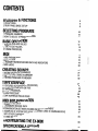
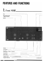
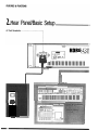
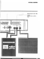
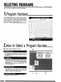
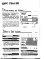
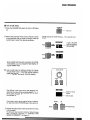
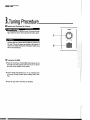
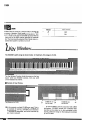
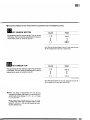
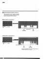
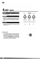
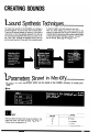
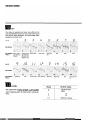
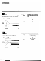
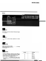
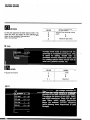
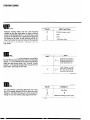
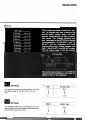
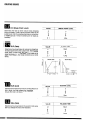
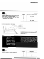
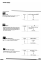
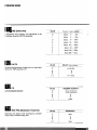
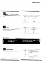
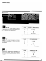
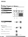
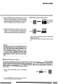
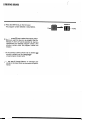
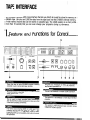
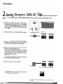
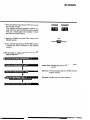
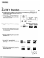
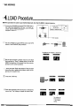
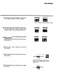
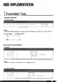
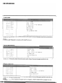
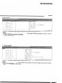
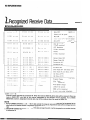
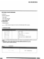
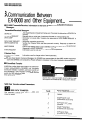
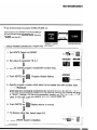
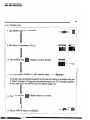
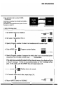
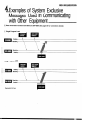
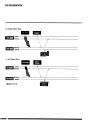
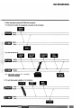
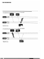
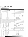
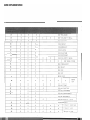
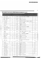
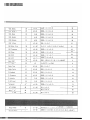
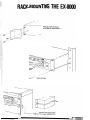
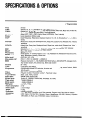
PROGRAMMABLE
POLYPHONIC SYNiHE
MODULE
OWNER’S MANUAL
KORG
FEATURES OF THE
KORG EX-8000
1 The EX-8000 is a 2U sized rackmountable 8-voice Polyphonrc Synthesizer Module, with a built-in Digital
Waveform Generator System (D.W.G.S.).
The DWGS has sixteen digitally encoded
waveforms stored in four 256 kilobit ROM
chips. These waveforms are digitally encoded samples of actual acoustic instru. merits‘ recreated by additive synthesis
techniques to enable more realistic
sound synthesis: (The sixteen waveforms
also include simple sawtooth and pulse
waveforms such as “ I’Y , l-7 ” and “ TL ”
which are found in conventional analog
synthesizers.)
The EX-8000 is 2U-sized so it’s rackmountable. It saves valuable space
and provides a wide range of sound
synthesis possibilities when used in conjunction with your MIDI synthesizer.
Thank you and congratulations on your choice of
the KORG EX-8000 Polyphonic Synthe Module.
To obtain optimum performance, please read this
manual carefully before using this synthesizer.
Uses two Digital Oscillators, analog
noise generator, and VCF and VCA
modules for sound synthesis. You
can enjoy the uniqueness of digital sound
plus quick and logical sound synthesis as
in analog control.
3
4
The EX-8000 accepts Initial Touch
(key velocity) and After Touch (channel pressure) data, so real-time control of output volume, timbre and pitch
modulation is at your fingertips when
used with a synthesizer featuring these
functions.
5
A programmable digital delay is included to store clear stereo effects
(Chorus, Doubling, Short Delay, and
Long Delay) for each of 64 tone colors in
the programmer.
6
7
Auto Bend is included for more realistic synthesis of human voice and
brass sounds.
Key Assign mode provides two polyphonic modes and two unison
modes, which are effective for playing solo or bass parts or using Portamento.
8
9
Built-in Portamento produces a gradual change in pitch from one note to
another.
The Key Window function limits the
area on the keyboard which one EX8000 controls, from one point on the
keyboard to another.
IMPORTANT SAFETY PRECAUTIONS
I LOCATION
To avoid malfunction do not use this unit in the following locations for long
periods of time:
0 In direct sunlight.
0 Exposed to extremes of temperature or humidity.
0 In sandy or dusty places.
n POWER SUPPLY
0 Use only with rated AC voltage. If you will be using this unit in a country
having a different voltage, be sure to obtain the proper transformer to
convert to rated voltage.
l To help prevent noise and degraded sound quality, avoid using the
same outlet as other equipment or branching off extension cords shared
by other equipment.
llNPUT/OUTPUT JACKS AND CONNECTION CORDS
Be sure to use standard “guitar” cables with phone plugs, such as the
cable supplied with this instrument, for input and output connections to the
rear panel of the EX-8000. Never insert any other kind of plug into these
jacks.
n
Preventing ELECTRICAL INTERFERENCE
As a microprocessor based device, the EX-8000 is extremely flexible in
operation, yet may possibly perform erratically if exposed to electrical interference from other electrical devices and fluorescent lamps. Avoid operating the EX-8000 near possible sources of interference. If something
seems to be wrong, try turning off the power, waiting about ten seconds,
them turning it back on. This resets the computer circuits to their initial
state so performance should return to normal.
n HANDLE GENTLY
Knobs and switches are designed to provide positive operation with a light
touch. Excessive force may cause damage.
n
MAINTENANCE
Wipe the exterior with a soft, dry cloth. Never use,paint thinner, benzene
or other solvents.
l KEEP THIS MANUAL
Store this manual in a safe place for future reference.
n MEMORY BACKUP
l To protect your programmed memory contents, the EX-8000 utilizes a
built-in rechargeable backup battery power supply. Battery life is rated
at five years or more, so replacement is recommended after five years.
Contact your Korg dealer or authorized service center at that time.
OFor maximum security, save your sound programs on tape, using the
built-in tape interface system. Then if memory contents are accidentally
erased or altered, you can simply load the data back into EX-8000 internal memory in seconds!
-4
CONTENTS
FEATURES & FUNCTIONS
6
6
IFRONTPANEL
2 REAR PANEL/BASIC SETUP
a
SELECTING PROGRAMS
10
10
10
1 PROGRAM NUMBERS
2HOWTOSELECTAPROGRAMNUMBER
BASIC OPERATION
12
12
12
14
1PARAMETERSANDVALUES
2HOWTOEDlTVALUES
3TUNlNG PROCEDURE
MIDI
1 MIDI PARAMETERS
2KEYWlNDOW
3TRANSMITTED/RECEIVED MIDIDATAANDINDICATORS
4 MIDIJACKS
CREATING SOUNDS
1FEATURESANDFUNCTlONSFORCONTROL
2SAVlNGPROGRAMDATAONTAPE
3VERlFYPROCEDURE
4LOADPROCEDURE
5TAPElNTERFACEPRECAUTlONS
.)
:'
21
21
21
40
1SOUNDSYNTHESlSTECHNlQUES
2PARAMETERSSTOREDINMEMORY
3WRlTlNGPROGRAMSTOMEMORY
TAPE INTERFACE
15
15
16
19
20
.
*
MIDI IMPLEMENTATION
1TRANSMlTTEDDATA
2 RECOGNIZED RECEIVE DATA
3COMMUNlCATlONBETWEEN EX-8000ANDOTHEREQUlPMENT
4 EXAMPLES OFSYSTEM EXCLUSIVE MESSAGES USED IN COMMUNICATING
WITH OTHER EQUIPMENT
5 EX-8000 BIT MAP
RACK-MOUNTING THE EX-8000
SPECIFICATIONS & OPTIONS ’
43
43
44
46
48
50
51
51
54
56
61
65
69
70
F-
FEATURES AND FUNCTIONS
1. Front Panel
Tune
Tape Interface Jack
(lkgh/Low Switch)
Volume
Phones
Tone Switch
Key Assign
(Poly 1: Poly 2: Unison 1: Unison 2)
Tape Switch
Write Switch
Program Switch
Program Write Key
-6
1
FEATURES&FUNCTIONS
Parameter List
MIDI Indicator
Indicators
Program No.
Parameter No.
Value
Power Switch
Value
(Up/Down)
Number Select
Buttons l-8
Parameter Switch
Bank Hold Switch
FEATURES & FUNCTIONS
1 .Rear Panel/Basic Setup
AC Cord Receptacle
I
MODEL EX-6000
UUL
AC 1OOV 50/60Hz 6W
lllllllllllllllllllllllll
I
AC cord
FEATURES 81 FUNCTIONS
MIDI Terminals: IN, OUT, THRU
OUTPUT
fLow/High Switch, Left/Mono,
kight) -
0
TO RAlN OR MOISTURE
SELECTING PROGRAMS
This explains how to select any of the 64 different sounds stored in the EX-8000’s memory. The PROGRAMMEl
section on the front panel is used for this purpose.
1P rogram Numbers
n
The EX-8000 can be store up to 64 different sound programs in its” internal memory. Each of these programs
has a number from 11 through 88 (the digits 0 and 9 are
not used). When you want to store a sound, you must
assign it a program number. When you want to recall
that sound, you select it by the same program number.
Writing programs
,____----__--___-___-~
I - ----- - ---------------
~
I
; - - - - ----__--c-_- ---_____--_____ - - - - - ----_ - ------ _I
2.Hovv to Select a Program Number
q
Features and Functions for Control
4
When this switch is activated (and its LED indicator is
on), different programs may be selected using the
NUMBER keys.
Press these keys to specify program numbers, which
range from 11 through 88. Programs are arranged in
eight “banks,” signified by the left digit, with eight
programs per bank, signified by the right digit; 8 x 8
= 64 total programs.
This holds the left “bank” digit so that you can use
single number keys to quickly access any of the eight
program numbers within a single bank.
I
1
Shows selected program number.
I
3
I
2
SELECTING PROGRAMS
q
How to Select a Program Number
PROGRAM
m fyi; sure the PROGRAM switch is set to ON. (LED
Q Press the NUMBER keys to select any program number (11 - 88).
p+-.---LEDIS ON
Example: To select program number...
. ‘,,V . ,
3
Press
LOAD
--.
* A dash aooears in
the right hand digit
until you select the
second digit. (This
means it is waiting
for you to select the
second digit.)
m How to Select Bank Hold
q
..* . . ,
BANK HOLD
Pressing the BANK HOLD switch preserves the left
digit of the selected program number.
An LED dot lights up to indicate
that the bank number (2) will not
change.
q
Now if you press any of the NUMBER keys, only the
right digit will change.
o
Only this digit changes when
you press the number keys.
q When you want to change to a program number in a
different bank, press the BANK HOLD switch again to
cancel BANK HOLD. You can now enter both digits
using the NUMBER keys.
[LED d
m
BANK HOLD
Now press
The LED dot goes out when
BANK HOLD is off.
t
lights.
. Parameters and Values
The various aspects of a sound, such as its pitch, timbre
and variations in volume, are called “Parameters”. To
create or change a sound, you adjust the values of each
of these parameters.
On the EX-8000, there are 49 parameters per program;
each parameter has a number, and each parameter’s
value is also represented by a number. These numbers
are shown on the front panel display. To create or
change a sound, you select parameters and change (or
“Edit”) their values.
When the EX-8000 stores a sound in memory or calls it
back from memory, it is actually storing and recalling
the values you have given it for the sound’s various parameters. All possible parameters and values are listed
in the “parameter index” chart on the right side of the
EX-8000 front panel. To create or change a sound, you
first use the number keys to select a parameter number,
then you use the edit slider and up/down keys to change
its value.
Parameters for oscillator 1
OSCl
16’ 8’ 4’
12 WAVEFORM
Value range: 1 16
.How to Edit Values
q
Features and Functions for Control
Shows selected parameter number.
Shows current VALUE for selected parameter.
This holds the Parameter Number’s left digit, so that
the NUMBER keys can be used to select only the
right digit. This can speed up Parameter Number selection when you are working on several parameters
within the same “family” (that is, having the same left
digit).
When this switch is on, you can create and modify
sounds by selecting different parameters (using the
NUMBER keys) and varying their VALUES (using the
EDIT slider and/or DOWN/UP buttons).
These keys are used to select different Parameter
Numbers (when the parameter switch is on).
Permits rapid and easy adjustment of parameter
VALUES (aspects of the sound) over a wide range.
Press to change parameter values up or down a step at
a time.
q
How to Edit Values
0 Press the PARAMETER switch so that its LED lights
up.
PARAMETERS
@I Refer to the parameter index chart to find the number
of the parameter that you want to change. Press the
number keys to select the desired parameter.
Example: Selecting VCF CUTOFF frequency.... This is parameter number
31, so....
p+-LEO is on
3
A dash in the right
1
Press
TAPE) SAVE
.
When the BANK HOLD switch is pressed, the left digit is locked; then, you can change the right digit by using the NUMBER keys.
q
Use the Edit control or Up/Down buttons to change
the parameter’s value. Suggestion: Use the Edit to
make large changes in value, then use the Up/Down
keys to “fine tune” the sound. (VALUE display)
I
VALUE EDITOR
I
The LED dot in the corner of the VALUE display indicates that the value of the currently selected parameter has been changed. The dot goes out if the return
to its original value.
~
DOWN
If you want to return to the original value of a parameter, just press both UP/DOWN keys at the same time.
v
press
0 Repeat steps Band Ofor each parameter that needs
to be changed.
To store your new sounds in memory, follow the operation procedures described in “WRITING PROGRAMS TO MEMORY” on page 40.
UP
A
:;;!I’;:-‘; m simultaneously.
m
BASIC OPERATION
$.Tuning Procedure
q
Features and Functions for Control
I
TUNE
This controls the EX-8000’s tuning. Turning it to their
right raises the pitch, and turning it left lowers pitch.
1
I
b
Pushing this key causes the EX-8000 to produce an
A4 tone. This is the same as playing a 4th octave A
note on the master keyboard. (A standard 440Hz tone
will not be produced.)
q
Tuning the EX-8000
0 Push the Tone Key. The EX-8000 will produce an A4
tone. (Be sure that volume control is not at “0” as the
tone will not be audible in this case.)
l
Tune to other instruments or to “A” on a strobe tuner
by turning Tuning Control while holding down Tone
Key.
@Tone will stop when Tone Key is released.
tI
A4
2
MIDI
1 .MIDI Parameters
The EX-8000 operates according to MIDI data transmitted from external sources. In order to receive
this external data, it is necessary to make sure that the EX-8000 Receive channel is the same as the
transmitting channel. It is also necessary to set the EX-8000’s Key Window function. If this is not
done correctly, proper operation will be impossible. Care must be taken in setting MIDI-related parameters.
The following parameters are MIDI-related.
q
CH (DATA RECEIVE CHANNEL)
This parameter is used to select a channel for data receive. At power-ON, the data receive channel is set for
that previously selected.
__
VALUE
DATA RECEIVE CHANNEL
CH-1
:
I
: !5
q
1
I
I
CH-16
ENA (Kind of Data Received)
This selects which kinds of received MIDI data the
EX-8000 will receive. At value 1 (NOTE DATA), the
EX-8000 receives only “note data.” At value 2 (All), it receives all MIDI data specified in the EX-8000 MIDI specifications (implementation notes.)
For example, if you don’t want program numbers to be
changed by some external device through MIDI, then
set this value to 1.
The most recently selected ENABLE value is retained
when power is turned on and off.
VALUE
Kind of Data Received
:
(NOTE DATA)
NOTE ON/NOTE OFF
1:
VW
All data
MIDI
li!ill
OMNI
When Omni is turned on, previous data is stored in the
memory. However, Omni mode can also be turned on
and off from the controlling (sending) device. When
Omni mode is off, then the EX-8000 receives MIDI data
sent only on the MIDI channel specified by parameter
84. The most recently selected Omni Mode value is retained when power is turned on and off.
VALUE
OMNI MODE
2
OFF
ON
:
l.Key Window
The EX-8000’s pitch range is shown below. At maximum, this range is Cl-C8.
The Key Window Function limits the areas on the keyboard which one EX-8000 controls, from one point
on the keyboard to another.
fl Example of Key Window
EX-8000 (B) controls this range
n
In this example, multiple EX-8000s are used. This is
an example of keyboard splitting. By changing the
sound parameters of each EX-8000, sound utilization
possibilities are expanded, and can be controlled by
one master keyboard.
C8
H When one EX-8000 is used in conjunction with a MIDI
synthesizer, EX-8000 sounds (for example Bass
sounds) can be added on to the synthesizer’s own
sounds, within the range on the keyboard controlled
by the EX-8000.
MIDI
8 Parameters Related to Key Window (These 2 parameters are not displayed on panel.)
, q
KEY WINDOW BOTTOM
’
POINT
VALUE
This parameter sets the low-end range. This can be set
in half-steps. The most recently selected point’s value is
retained when power is turned on and off.
Note: When the Key Window Bottom is set to Cl, notes lower than note
23 will be registered as the same note in octave 24-35.
q
KEY WINDOW TOP
This parameter sets the high-end range. This can be set
in half-steps. The most recently selected point’s value is
retained when power is turned on and off.
VALUE
I
POINT
High C
I
Note: When the Key Window Top is set to CB, notes higher than note 1013
will be registered as the same note in octave 97-108.
n
When the values of parameters 87 and 88 are
changed by half-steps, the sharps (1) are shown by a
decimal point on the display: Cl - C.l - dl - d.1 Flats
( b ) are not shown.
When editing, value can be approximated by using
the Edit Control (Edit Control changes notes in major
thirds-Cl -El -G # 1 -C2), and set exactly by pushing the Up/Down keys.
MIDI
Eil Relationship Between Key Bottom and Key Top
These parameters can be set anywhere throughout
the 85 notes on the keyboard, however there are 2
particular relationships which are possible.
H When Key Bottom is set lower than Key Top.
Plays these notes
n When Key Boltom is se! higher than Key Top.
Plays these notes
* However, when this setting is used, note data other than that set in
EX-BOO0 is cancelled even if it is received.
MIDI
3 .Transmitted/Received
MIDI Data and MIDI Indicators
0 Received MIDI Data
W Note OFF
n Note ON
n Control change:
No. 1 OSC modulation
No. 2 VCF modulation
No. 7 Vdlume
No. 64 Damper pedal on/off
No. 65 Portamento on/off
H Program change
n Channel pressure (After Touch)
W Pitch bender change
n All notes OFF
n Omni MODE OFF
n Omni MODE ON
n Active sensing
H System exclusive information
q
Transmitted MIDI Data
n
Program Change
Wystem Exclusive Messages
q
MIDI indicator
The MIDI indicator lights when the above MIDI data is
received. When it is not properly received the indicat or
does not light, so verification is simple.
MIDI
4.MIDI Jacks
Rear Panel
MIDI
D
Receives MIDI data.
MIDI OUT is used only when transmitting internal
MIDI data to external MIDI equipment, so it is not normally used. (Does not transmit program change data,
etc.)
THRU
I
MIDI, THRU
OUT
I
MIDI OUT
Resetting MIDI
If the EX-8000 is being used in a MIDI connected system and starts producing erratic results (making a
continuous sound, going out of tune, producing erratic modulation, etc.) press the front panel WRITE key.
This resets the circuitry. However, if the write switch
is set to ENABLE, the WRITE made is effected. Push
the WRITE key after setting to DISABLE.
I
MIDI IN
i
Retransmits unchanged MIDI data received through
the MIDI IN Jack.
q
IN
WRITE
Press
CREATING SOUNDS
1 .~ound Synthesis Techniques
To create new sounds on the EX-8000, you change or
edit old programs. You do not start with a “blank slate”.
There are 64 sounds already in memory. If you have a
new sound in mind, the easiest approach is to first select a sound that resembles the sound you want to create. Then “edit” (change the selected sound until you
get the sound you want. If you don’t find a similar sound,
it doesn’t matter; start with any sound you like.)
After you finish editing your sound, you store it into
memory. At this point you can give it a different program
number (thereby preserving the sound you started with)
or the same program (thereby erasing or “overwriting”
the old sound). (See page 40 Program Write)
,Z.Parameters Stored in Memory
This section describes parameters which can be stored in the EX-8000’s memory to create your
sounds.
q 0SC.l
q
OCT
Here you select the basic pitch range of oscillator 1. The
higher the value, the lower the pitch. You have three
choices which correspond to 16’ (16 foot), 8’, 4’.
CREATING SOUNDS
m WF
The choice of waveform will have more effect on the
tonal characteristics (timbre or tone color) of the sound
than will any other parameter. You have sixteen basic
waveforms to choose from.
3
I-
VALUE
n
fC-.
WAVEFORM
r
11
-~~zF-----+-s------+Clarinet and ana- Acoustic piano
INSTRUMENT Brass, strings,
and analog syn- log synthesizers
FAMILY
(harmonics comthesizers
ponents are the
same with “nL’)
Electric piano
Electric piano
(hard)
Clavi
Brass
Organ
r’ b
VALUE
WAVEFORM
+----+
INSTRUMENT
FAMILY
Ra
Saxophone
Violin
Acoustic guitar
+&----4++----b
Guitar (distorted)
LEVEL
Sets output level (volume) of oscillator 1. This is useful
for adjusting overall volume to match other programs,
and for balancing OSCl with OSC2 and/or noise as desired.
Electric bass
Digital bass
Bell
Organ and whistle
VALUE
OUTPUT LEVEL
L7
No sound from
osci
I
3:
I
Maximum volume
CREATING SOUNDS
Oscillator Used for AUTO BEND
OSC SEL
No oscillator (AUTO BEND OFF)
Selects the oscillator(s) for AUTO BEND.
OSCl
osc2
OSCl and OSC2
BE!
MODE
VALUE
Pitch Change after Key Pressing
Selects between UP and DOWN modes. In UP mode,
the pitch rises to the pitch of the pressed key. In
DOWN mode, the pitch falls to the pitch of the pressed
key.
Pitch
t
Pitch change
P r e s s e d
key pitch
IKey pressing
c
Time
23-
TIME
Sets a period of time from the key pressing to the time
when the pitch reaches the pitch of the pressed key.
VALUE
Time Period from Key Pressing
to the Pitch’s Reaching the Key
Level
VALUE
Pitch Change width
I7
l-1
No pitch change
(AUTO BEND OFF)
Pitch
Pressed
key pitch
Key pressing
El
Titne
INT
Specifies the pitch where pitch change starts.
I
7 I
3 ,
Key pressing
Time
I
Max. bend width
(2 octave)
CREATING SOUNDS
lm
OCT
As with OSCl , you have a choice of three pitch ranges:
4’, 8’, and 16’.
Once again, you have sixteen waveforms to choose
from.
Adjusts output level as in OSCi.
Raising levels of this parameter or of OSCl 0 3) too high
may cause distortion.
lm
INTRVL
This lets you transpose or offset the pitch of OSC2 so
that it sounds a constant interval above OSCl. Selectable intervals are: Unison (same as OSCl), a minor 3rd,
major 3rd, perfect 4th, or perfect 5th above.
*You will get different intervals (from those shown
above) depending on tne OCTAVE WUeS for the two
oscillators.
VALUE
INTERVAL
Unison
Minor 3rd
Major 3rd
Perfect 4th
Perfect 5th
CREATING SOUNDS
For fine pitch adjustment of OSC2 relative to OSCl. The
higher the value, the greater the pitch difference between the two oscillators. Detuning can help achieve a
fatter, more animated sound.
q
PITCH DIFFERENCE
L7
Minimum (no detuning-same
pitch)
I
s
I
Maximum (25 cents)
NOISE
‘rn
LEVEL
Adjusts noise volume.
q
VALUE
VCF
VALUE
LEVEL
CREATING SOUNDS
VALUE
TIMBRE
This determines the cutoff frequency of the low-pass
filter. The higher the cutoff frequency, the less effect the
filters have on the basic waveforms (since more frequencies are passed).
At the highest value, 63, all harmonics are passed. The
lower the value, the more harmonics are cutoff, so the
sound becomes progressively rounder or less bright.
Low-pass filter’s function and cutoff frequency
ta
Frequencies lower than cutoff I,
frequency are passed.
I
I
0
\
b
Frequency
t
Cutoff frequency
c
Value
This emphasizes the harmonics near the cutoff frequency, producing a characteristic peaky or bandpass type
of sound.
The higher the value, the higher the resonance peak
and the more obvious the effect. At or near the maximum value 31, the VCFs go into self-oscillation, producing a pure sine wave, which can be used as an additional sound source for special effects. The pitch of the VW
tone is affected by the Cut Off, Keyboard Track, EG INT,
and MG VCF parameters.
53
VALUE
EFFECT
l-l
Ll
None
;I:1 ~$fnodscillation~ v
e
r
y
“pesky”
Harmonics near cutoff
frequency are boosted.
c
Frequency
Cutoff frequency
CREATING SOUNDS
KBD Track Effect
VALUE
Keyboard tracking affects how the cutoff frequency
changes as you play notes higher or lower on the keyboard. At full tracking (VALUE = 3), cutoff rises in exact
proportion to keyboard pitch, maintaining the same relative timbre for all notes. At half tracking (VALUE 2) it
rises a half octave for every full octave on the keyboard.
(The difference will be obvious if resonance is set to a
high value.)
5l
POL
+25%
I?
t50%
3
VALUE
Determines how the VCF cutoff frequency is affected by
the VCF EG (Envelope Generator). With normal polarity
(VALUE = l), the cutoff frequency rises during the EG’s
Attack and falls during Decay. Use “inverted” polarity
(VALUE = 2) for special sounds where you want the opposite effect. (See page 29 VCF EG)
q
EG
The “EG Intensity” parameter determines how much
the VCF Envelope Generator (EG) will affect the cutoff
frequency. The higher the value, the more obvious the
change in tone color (timbre). (See page 29 VCF EG)
0 0% (No change in cutoff)
c
:
VALUE
I7
U
I
3 :
I 100% (Max. effect)
P-7
L-J
POLARITY
Cutoff frequency is swept up
during the attack portion of
the envelope, and down during the decay portion, etc.
Cutoff frequency is swept
down during the attack portion, and up during the decay portion of the envelope.
fNTENSlTY
No effect
I
Maximum change in tone color.
CREATING SOUNDS
q
VCF EG
q
ATK (Rate)
.
VALUE
ATTACK TIME
VALUE
DECAY TIME
E
Short
The parameter controls how long it takes for the VCF
EG output voltage to rise from zero to its maximum
level.
This parameter controls how long it takes for VCF EG
output voltage to fall from its maximum level (after an attack time) to the break point level.
I
3:
I
Long
CREATING SOUNDS
em
B P (Break Point Level)
This parameter determines the VCF EG output voltage
after the decay time. If this is set to the same value as
the sustain level, then the envelope becomes a conventional ADSR type.
VALUE
BREAK POINT LEVEL
I7
(J
0
VALUE
1
SLOPE TIME1
This parameter controls how long it takes for the VCF
EG output voltage to change from the break point level
to the sustain level.
m
SUS (Level)
This parameter determines the VCF EG output voltage
after the slope time.
This parameter determines how long it takes for the VCF
EG output voltage to fall to zero level after the note is released on the keyboard.
VALUE
SUSTAIN LEVEL
l-l
l-l
0
3JIII
Touch Sensitivity.
Max.
VALUE
RELEASE TIME
::
Short
I
3:
VALUE
Controls the degree of timbre change according to the
speed of playing a note on the keyboard.
When the value is made larger, the degree of timbre
change becomes greater. (Actually, change of EG output becomes larger.)
Set valtie at “0” when using a MIDI keyboard without
I
I
Long
1 DEGREE OF TIMBRE CHANGE
Max. change
.
CREATINGSOUNDS
Ex: When the value is changed for a fixed envelope.
A
~-Valve set to 7.
Valve set to 3.
Value set to “0”
. (No change)
Time
RVCA EG
m ATK
(Rate)
VALUE
ATTACK TIME
Controls how long it takes for the volume to rise from
zero to its maximum level after a note is played on the
keyboard.
VALUE
Determines how long it takes for the volume to fall from
its maximum attack level to the break point level.
I
DECAY TIME
I!.:
Short
t
t
1
3;
1
Long
q
B P (Break Point Level)
VALUE
BREAK POINT LEVEL
VALUE
SLOPE TIME
::
Short
Determines the level at which volume stops dropping
during the decay. If this is set to the same value as the
sustain level, then the envelope becomes a conventional ADSR type (as if it had no break point or slope parameters).
Determines how long it takes for volume to change from
the break point level to the sustain level. Note that if the
break point is lower than the sustain level, then the
slope functions as a second attack. If the break point is
higher than sustain, then slope functions as a second
decay.
I
3:
E=3tt
Second attack
I
Long
Second decay
I
Determines the level at which volume is held after the attack, Uecay, and slope phases are completed, for as
long as the note is held down on the keyboard.
REL (Rate)
Determines how long it takes for the sound to fade away
after you release the note on the keyboard.
VALUE
SUSTAIN LEVEL
::
0
I
3 I
J I
I
Max.
VALUE
RELEASE TIME
I7
1-l
Short
I
I
-I
3
I
I
Long
CREATING SOUNDS
IiN
VEL
VALUE
DEGREE OF VOLUME CHANGE
Control the degree of volume change according to the
speed of playing a note on the keyboard. When the
value is made larger, the degree of volume change becomes larger. Set value at “0” when using a MIDI
keyboard without Touch Sensitivity.
No change
I
Max. change
Ex.: When the value is changed for a fixed envelope.
Value set to “7”.
Value set to “3”.
Value set to “0” (No change)
Time
q
The EX-8000 covers a wide range of sound, so a “click”
may be produced when a key is pressed, depending on
parameter settings.
MG
WF
VALUE
I
WAVEFORM
Selects the waveform to modulate oscillator/VCF.
33-
CREATING SOUNDS
m
FREQ
Determines the speed of the cyclic pitch or tonal variation. The higher the value, the faster the speed.
VALUE
SPEED OF VIBRATO OR FILTER MOD
::
Slow
7I
:I
I
I
Fast
I
VALUE
I
Determines the amount of delay following key depression prior to the onset of vibrato or other modulation effects. At 0, there is no delay, and modulation begis immediately when the first note is played. The higher the
value, the longer the delay.
OSC (vibrato depth)
Controls the amount of pitch variation in the vibrato effeet (that is, the depth of frequency modulation).
m VCF (filter mod depth)
DELAY TIME
None: modulation effect starts
VALUE
VIBRATO DEPTH
I7
No effect
1-l
I
3:
VALUE
I
Deep modulation
1
Controls the depth of cyclic filter mod effects (that is, the
depth of VCF cutoff frequency modulation).
FILTER MOD DEPTH
No effect
3
-I
I
I
I
Deep modulation
CREATING SOUNDS
q
BEND
osc
Determines the maximum change in pitch produced by
moving the joystick or bender, in exact semitone steps.
The higher the value, the greater the pitch change (up to
1 octave).
VALUE
2
I
I17
L
Enables or disables “sweeping” of the VCF cutoff frequency via the joystick, or bender.
When the VCF parameter value is 1 (ON) then moving
the joystick to the right produces a brighter sound; moving it to the left produces a darker or duller sound.
fIl DIGITAL
DELAY
PITCH BEND
None
I
(change in semitone steps
according to the value)
1 octave
VALUE
JOYSTICK VCF EFFECT
l-l
u
:
OFF
ON
CREATING SOUNDS
m
TIME (Delay time)
VALUE
DELAY TIME RANGE
Adjusts delay time coarsely. Fine adjustment is performed by using the FACTOR parameter.
About
2 -
4ms
About
4 -
8ms
About
8 -
16ms
About
16 -
32ms
About 32 -
64ms
About 64 - 128ms
About 128 - 256ms
About 256 - 512ms
FACTR
Performs fine adjustment of delay time in a range specified by the TIME parameter (71).
: :I
Controls feedback quantity.
MOD FRQ (Modulation frequency)
Determines the speed of the low-frequency oscillator
output used to modulate delay time.
(xl) Long
VALUE
FEEDBACK QUANTITY
l-l
1-1
0% (No feedback)
I
:5
Ic1&l
I
I
100%
VALUE
FREQUENCY
::
Slow
3JI 1
I
Fast
\
!
CREATING SOUNDS
‘I
!
•
6
Determines the modulation depth for delay time modulation.
a
MOD INT (Modulation intensity)
VALUE
MODULATION DEPTH
No modulation
I
Large
m
LEVEL
Control the volume of effect sounds mixed in direct
sound (the sound without delay effect).
q
VALUE
I
LEVEL
I
f
PORTAMENTO
b
TIME (Portamento)
VALUE
PORTAMENTO TIME
l-l
!A
No portamento effect (instant
change)
3 :
Slow change in pitch from one
note to the next.
Determines how gradual the change in pitch is.
CREATING SOUNDS
•j AFTER ToucH
q
OSC MG
Determines the depth of vibrato controlled by the pressure on the keyboard. However this is not effective when
64 is at its highest value in MG parameter.
J3
Max. change
I
q
VCF
Determines the change of tone brightness controlled by
the pressure on the keyboard. However this is not effective when sustain level 45 is at maximum level in VCF
EG parameter.
VALUE
BRIGHTNESS CHANGE
I7
1-f
No change
I
I
3
!
VALUE
Max. change
CHANGE OF VOLUME
Determines the change of volume controlled by the
pressure on the keyboard. However this is not effective
when sustain level 55 is at maximum level in VCA EG
parameter.
3
I
Max. change
7-7-.-.~--,
CREATING SOUNDS
@ KEY ASSIGN
IIPOLYl Mode
This mode is used for normal polyphonic playing. The
EX-8000’s eight voices are assigned sequentially as
notes are played. If you play more than eight notes, then
the most recent notes will cancel out the earliest notes
still sounding. In this mode, sounds using long release
times will create an effect of “overlapping” notes, which
will create a spacious sound.
n POLY2 Mode
This is most useful for certain instrumental sounds, and
for sounds using polyphonic portamento effects. If a one
note passage is being played, the first synth voice (out
of eight) is used continuously. If two notes are played,
the first two voices are used continuously, and so forth.
WNISON 1,2 Mode
This mode assigns all eight voices to each key depression, following a “last note played” priority system. Because all eight voices are automatically detuned when
this mode is selected, this produces a very fat, rich
sound. This mode is useful when the EX-8000 is used
for soloing or playing bass parts.
UNISON 1 causes the envelope to retrigger every time a
new key is pressed, regardless of other keys being held.
UNISON 2 wilt result in single trigger operation (only the
first key pressed will activate the envelope).
Synth Voices Used
When one note is played, the eight voices are used sequentially.
Synth Voices Used
When one note is played, the first voice is always used. When
two or more notes are played, other voices also are used.
Synth Voices Used
All voices are used for each note played
CREATING SOUNDS
3, Writing Programs to MemoryJ
fl Features and Functions for Control
Used to specify the program number.
I
Used to start writing programs.
Shows presently selected program number.
When this switch is set to ENABLE, memory write
operation is enabled.
q
Program Write Procedure
Create a sound (as described in the previous section
of this manual).
q
4
I---ENABLE m DISABLE
Set the front panel WRITE switch to the ENABLE
posision.
WRITE
q Press the WRITE key on the front panel.
m At this time, the program number flashes.
Flashing
CREATING SOUNDS
@I Use the NUMBER keys to select the program number
where you want to store your sound. The new sound
is stored in the specified memory location immediately after the program number selection. (Previous contents of the selected memory location are erased.)
Example: Storing your sound at program number 34.
3
Press
VERIFY
sr A selected parameter can be stored in memory with a
program. It will be very helpful if you specify a parameter (e.g., cutoff frequency) during programming
which will be edited often during live performance.
-
.‘, . . ,
m Display will show a
dash in the right
digit. (Waiting for
input)
m
4
Press
CANCEL
Your sound now occupies the memory space called
program number 34.
The previous contents of the space have been erased.
r - - - - - _ _ _ _ _ _ _ _ _ _ - _ _ _ - _ - - - _ - - - ‘1
[ Caution:
1 Be sure to return the front panel WRITE switch to
1 the DISABLE position after completing this proce-’
I dure. This helps protect against accidental over; writing (erasure) of memory contents.
I If you accidentally press the WRITE key and do
1 not wish to “write” a program into memory, simpi ly switch the front panel WRITE switch to the DIS; ABLE position. This will cancel the write proce, dure.
L-- --____-______ ---_-. --_---- -I
q
Repositioning Sounds in Memory
If you always use particular sounds in the same order in a song or stage performance, then you can simplify
matters by storing the sounds in the same order in which they will be used. That is, store your first sound under
program number 1, the second sound under program number 2, and so on. You can then use a footswitch to
advance from one sound to the next, as you need it. Sounds are repositioned by copying them from their present program number to a different program number.
0 Set the front panel WRITE switch to the ENABLE
position.
D Use the NUMBER keys to select the program number
of the sound that you want to reposition.
7
ENABLE m DISABLE
4
CREATING SOUNDS
,
a Press the WRtTE key on the front panel.
The program number selected in stepOflashes.
1~ Use the,NUMBER keys to select the program number
where you want the sound to be located. When the
s.electiDn j.s done, the sound specified by step m is
repositioned to the selected program number. (The
previous contents under the program number are
erased.)
fi If the previous contents should not be erased, the
previous contents must be repositioned to another
unused program location before step @J.
L!Z Follow step @ through @ above, to rearrange your
sounds in the order that is most convenient for performance.
WRITE
Press
-
TAPE INTERFACE
The EX-8000 is equipped with a tape interface that lets you SAVE all sound data stored in memory on
cassette tape. Later you can LOAD the data from the tape back into the EX-8000’s internal memory.
,A wide variety of sound data can be stored on cassette tape. The LOAD operation is so fast (a little
more than 10 seconds) that you can even change your programs during a performance.
1 Jeatures and Functions for Control5
TAPE
TUNE
PROGRAMMER
KEY ASSIGN
q q
PRM;RAM
DISABLE
PARAMETER
f-, fj0 fj
Press this key to write EX-8000 program memory
contents to your connected tape recorder.
This gives you messages to keep you informed of
tape interface operations and possible problems.
Press this button to read data from your tape recorder
while playing back a tape.
This is set to ENABLE to enable LOAD operation.
This is used to check recorded data (immediately
after the SAVE or LOAD procedure) to make sure that
it has been properly performed.
If an error occurs during SAVE or LOAD operation,
pressing this key lets you start over again, if you
press the CANCEL key during SAVE, LOAD, or VERIFY operation, it will immediately interrupt and cancel
the operation.
This switch is set to ENABLE to make tape interface
possible.
This switch is used to make the EX-8000 match the
output level of the connected tape recorder during
VERIFY or LOAD operation.
TAPE INTERFACE
1 Saving Program
Data on Tape.
W Follow the procedures below to write EX-8000 program memory contents to your connected tape recorder.
q Connect the EX-8000 front panel TO TAPE jack to
I
TAPE
I
the microphone (mic) input jack on the tape recorder.
You may need a plug adaptor or special connection
cord if the input jack is not the usual “mini jack” size.
When the input of the tape recorder is stereo, use the
left channel.
/ZJ Set the TAPE switch to the ENABLE (ENA) position.
The DISPLAY will now appear as shown here.
TAPE
ENABLE m DISABLE
m
q
Prepare the tape recorder for recording. Begin recording. and let the tape advance until it is past the
leader tape (at the beginning of the cassette).
@I Press the recorder’s pause key at the point from
which you will begin recording data.
At this point, the EX-8000 is sending out a test tone
as a reference for setting recording level (input level)
on the tape recorder. Adjust the tape recorder’s recording level as you would normally (refer to tape recorder’s instruction manual).
q After setting recording level, release the pause key so
that the recorder begins recording.
q Press the SAVE key on the EX-8000.
TAPE b SAVE
(A 5 8; E message indicates SAVE mode)
The EX-8000 will start sending data and the DISPLAY will appear as shown here.
This shows the bank number (left digit of program number) 1-8 dung
data output.
TAPE INTERFACE
q
When the DISPLAY again shows TAPE, then you can
stop the tape recorder.
This completes the SAVE procedure. However, it is
good practice to repeat the SAVE procedure several
times, as a hedge against the possibility of losing
data because of tape dropouts.
B Reset the EX-8000 front panel TAPE switch to the
DISABLE position.
a Do not change any settings on the EX-8000 until you
complete the VERIFY procedure (in the following
section).
TAPE
ENABLE
DISABLE
e
n If you listen to a tape of recorded data, you will
hear the following tones:
-.I.
*
.
.
,
-a
-._
Leader tone: Indicates the start of VERIFY and LOAD
operations.
Data tone: The actual digital data from EX-8000 sound
program memory.
End tone: Indicates the end of the operation.
TAPE INTERFACE
3 n VERlFYProcedure
n The VERIFY procedure should always be used immediately after you finish a SAVE (or LOAD) operation. This
is to make sure that data has been properly recorded. It is also useful for determining the best playback level
setting for your recorder.
q Connect the EX-8000 front panel FROM TAPE jack to
the output jack (earphone, line out, etc.) of your
recorder. Set the High/Low switch to match your tape
recorder’s output signal level.
TAPE
LOW m HIGH
TO
Recorder output lack
HIGH/LOW
FROM
- From recorder
This shows the EX-8000 is in the tape interface mode.
B Set the EX-8000 panel TAPE switch to the ENABLE
position.
TAPE
l3l Set the tape recorder’s playback volume a bit higher
than usual. If the recorder has tone controls, set them
to the center positions.
q Rewind the tape. Begin tape playback. Stop the tape
(using the stop or pause key) when you reach the beginning of the leader tone.
q Press the VERIFY key on the EX-8000.
The DISPLAY will show “VERIFY” to confirm the
VERIFY mode.
VERIFY
q Start the tape recorder (press the play key or release
the pause key). The DISPLAY will show “VERIFY” to
confirm the VERIFY mode.
L
The DISPLAY will
show the bank
number (l-8) for
the VERIFY operation.
TAPE INTERFACE
q
If the recorded data match the EX-8000 internal
memory data then the DISPLAY will give a “Good”
message. The DISPLAY will appear as shown here if
data is successfully verified.
0 If you get an error (Err) message as shown here
Press the CANCEL Key, lower (or raise) the tape recorder’s output volume, and repeat steps&$l- lj$J
CANCEL
0 If the DISPLAY does not change after ten seconds
of tape playback
Raise the tape recorder’s output volume level and repeat steps m- @I.
q
When you get a “Good” message, you can stop the
tape recorder. Make a note of the recording level,
playback level, and HIGH/LOW switch setting that resulted in the “Good” message.
•I Set the EX-8000 front panel TAPE switch to the DISABLE position.
m
TAPE
ENABLE
DISABLE
w
r ______ -__------ ------ --------------------------,
1
,
1
(
)
Note: You will not get a “Good” message if the recorded data is different in any way from the data in the
EX-8000’s internal memory. If you change a single parameter value or the key assign mode and then try
VERIFY, you will get an error “Err” message.
If you still don’t get a “Good” message after trying many different output level settings on the tape
recorder (and HIGH/LOW switch settings on the EX-8000) then your recording level may be wrong. Try
saving again at a different recording level.
L ________ ------ -..--- ~~-----.-- ----- - ---- -----------_I
/
1
I
I
1
I
TAPE INTERFACE
4. LOADProcedurec
H This procedure is used to put recorded data back into the EX-8000’s internal memory.
q
Connect the EX-8000 front panel FROM TAPE jack to
the output jack (earphone, line out, etc.) of your recorder. Set the HlGHlLOWswitch to match your tape
recorder’s output signal level.
q
Set the EX-8000 front panel WRITE switch and TAPE
switch to the ENABLE (ENA) positions.
TAPE
ENABLE m DISABLE
-
The DISPLAY will now appear as shown here.
m
m
q
Set the tape recorder’s playback volume to the level
that produced a “Good” message when you use the
VERIFY procedure. If the recorder has tone controls,
set them to the center positions.
i!$ Rewind the tape. Begin tape playback. Stop the tape
(using the stop or pause key) when you reach the beginning of the leader tone.
0 Press the LOAD key.
LOAD
@ Start tape playback (press the play key or release the
pause key). The Display will appear as shown here.
This shows the
bank number (1
- 8) if data is
loading.
TAPE INTERFACE
q
If the data has successfully loaded into internal memory the DISPLAY will give a “Good” message.
m
m
A “Good” message indicates the completion of loading.
I If you get an error (Err) message as shown here
Press the CANCEL Key, lower (or raise) the tape
recorder’s output volume, and repeat steps@- q .
n If the DISPLAY does not change after ten second&
of tape playback
Raise the tape recorder’s output volume level and repeatsteps@- q J.
m m
181 When you get a “Good” message, you can stop the
tape recorder.
@ Set the EX-8000 front panel WRITE switch to the DISABLE position.
ENABLE
Follow the VERIFY procedure to check if the data
from the tape has precisely loaded into the programmer or not.
@Set the EX-8000 front panel TAPE switch to the DISABLE position.
TAPE
TAPE INTERFACE
s.Tape Interface Precautions
1
, 1 ‘Transmitted Data
*
q CHANNELMESSAGES
I
q PROGRAMCHANGE
,
1100 n n n n
O P P P
Program Change
P P P P
P P P P P P P=O-63
* nnnn - 0 - 15: channel number specified by parameter 84.
NOTE:
1. PROGRAM NUMBER (Oppppppp) correspond to DISPLAY NUMBER on the PANEL which will be the following:
DISPL$;,NUMBER
#12
PROGRAY NUMBER
.
,l
* 62
e 63
#87
#88
q SYSTEM EXCLUSIVE MESSAGE
q DEVICE ID
IIII 0 0 0 0
Exclusive status
0100
KORG
ID 42l-l
Format
ID 3*H ( * =ch) ( N O T E 6 )
0 0 1 0
0011 n n n n
0 0 0 0
001 I
EX -8000 ID 03H
IIll
OIlI
EOX
* nnnn = 0 - 15: channel number (channel provisions within System Exclusive Messages) specified by parameter 84.
NOTE
2. If DEVICE ID REQUEST is received, DEVICE ID message will be sent.
q DEVICE ID REQUEST
Illi 0 0 0 0
Excluswe stat us
0100
0010
KORG ID 42H
0 1 0 0
n n n n
F o r m a t I D 4*H (* =ch) (NOTE 6)
III1
OIlI
EOX
* nnnn = 0 - 15: channel number (channel provisions within
I
System Exclusive Messages) specified by parameter 84.
51-
3 DATA DUMP
III1
0 0 0 0
Exclusive status
0 1 0 0
0 0 1 0
KORG
F o r m a t I D 3*H (* =ch) (NOTE 6 )
ID 42H
0 0 1 I
n n n n
0 0 0 0
0 0 1 I
EX -8000 ID 03H
0 1 0 0
0 0 0 0
Data Dump 40H
o v u v
v v v u
D a t a 51 B y t e s
( S e e E X -.8000 B I T M A P )
ovvv
vvvv
IllI
0111
EOX
* nnnn = 0 - 15: channel number (channel provisions within System Exclusive Messages) specified by parameter 84.
NOTE
3. If DATA DUMP REQUEST is received, DATA DUMP will be sent.
/-4J DATA DUMP REQUEST
0 0 0 0
Exclusive status
0 1 0 0
0010
KORG
001 I
n n n n
F o r m a t I D 3*H ( * =ch) ( N O T E 6 )
0 0 0 0
001 I
EX -8000 ID 03H
III1
I D 42H
0 0 0 1
0 0 0 0
D a t a Save R e q u e s t IOH
IIII
0111
EOX
I-
* nnnn = 0 - 15:channel number (channel provisions within System Exclusive Messages) specified by parameter 84.
q WRITE COMPLETED
IIll 0 0 0 0
Exclusive status
0 1 0 0
0 0 1 0
KORG
ID 42H
I
0 0 1
3*~ ( * =ch) (NOTE 6)
I
n n n n
Format
0 0 1 0
001 I
EX -8000 ID 03H
0 0 0 0
0 0 0 1
Write C o m p l e t e d 2lH
IllI
0111
EOX
D
* nnnn = 0 - 15: channel number (channel provisions within System Exclusive Messages) specified by parameter 34.
NOTE
4. If WRITE REQUEST is received and program write is completed, a WRITE COMPLETED message will be sent.
MIDI IMPLEMENTATION
a WRITE ERROR
III1
0 0 0 0
Excluslue s t a t u s
0 1 0 0
0 0 1 0
KORG
0011
n n n n
F o r m a t I D 3*H (* =ch) ( N O T E 6 )
0 0 0 0
001 I
EX-6000 ID 03H
0 0 1 0
0 0 1 0
Write e r r o r 2 2 H
IIII
0111
EOX
ID 42H
* nnnn= O-15: channel number (channel provisions within System Exclusive Messages) specified by parameter 84.
NOTE
5. If WRITE REQUEST is received and program write is not completed (if WRITE DISABLE is chosen on the rear
panel), a WRITE ERROR message will be sent.
[51 WRITE REQUEST
Excluswe s t a t u s
III1
0 0 0 0
0 1 0 0
0 0 1 0
KORG
ID 42H
0011
n n n n
Format
I D 3*H (* =ch) ( N O T E 6 )
0 0 0 0
00-I
0 0 0 1
0 0 0 1
Write Request I IH
O P P P
P P P P
Program Number ( p p p p p p p = 0 -63)
III1
OIlI
EOX
I
EX -8000 ID 03H
+ nnnn = 0 - 15: channel number (channel provisions within System Exclusive Messages) specified by parameter 84.
NOTE
6. When a Format ID is received, channel numbers set at parameter No. 84 and messages with abnormal numbers
are ignored. (Not related to OMNI mode.)
MIDI IMPLEMENTATION
I
1R
I ecognized Receive Data
0 CHANNEL MESSAGES
1 0 0 0
n n n n
O k k k
k k k k
oxxx xxxx
Note OFF
1 0 0 1
n n n n
O k k k
k k k k
ovvv vvvv
Note ON
1 0 0 1
n n n n
O k k k
k k k k
0000 000’0
Note OFF
1011 n n n n
0 0 0 0
0 0 0 1
. ovvv vvxx
0% Modulatton
1011 n n n n
0 0 0 0
0 0 1 0
ovvv vvxx
VCF Modulation
(NOTE I)
Velocrty WIII b e I g n o r e d .
(
N O T E
I)
v v v v v v v= I -127 (I5 steps)
(
N O T E
I)
( 5 Btts resolutron)
( 5 Bits resolutron)
1011 n n n n
0000
01
I
I
ovvv vvvv
Volume
( 7
1011 n n n n
0 1 0 0
0 0 0 0
0 0 0 0
0 0 0 0
Brts resolvtron)
Damper Pedal OFF
1011 n n n n
0100 0 0 0 0
0111
III1
Damper Pedal ON
1011 n n n n
0 1 0 0
0 0 0 1
0 0 0 0
0 0 0 0
Portamento OFF
loll n n n n
0 1 0 0
0 0 0 1
OIlI
Iill
Portamento ON
I011 n n n n
OIlI
1011
0111
1100
1011 n n n n
OIlI
II01
1011 n n n n
0111
Ill0
1011 n n n n
OIlI
III1
0000
0000
0000
xxxx
0000
All Notes OFF
1011 n n n n
0000
0000
0000
oxxx
0000
1 1 0 0
n n n n
O P P P
P P P P
Program Change
I101 n n n n
o v v v
v v v x
After Touch
I I
o x x x
x x x x
Omm M o d e O F F ( A l l N o t e s O F F )
Omnr M o d e O N ( A l l N o t e s O F F )
(All Notes OFF)
(All Notes OFF)
(
N O T E
2)
( 6 Bits r e s o l u t Ion)
I O
n n n n
O b b b
b b b b
Pitch Bender Change
L S B will b e I g n o r e d .
M S B WIII b e r e c o g n i z e d .
(b b b b b b b=64 : C E N T E R )
* nnnn = 0 - 15:
Channel number specified by parameter 84. When the mode is OMNI ON, all the data will be received. When the
mode is OMNI OFF, only data of the channel designated by the parameter will be received. As to MODE
MESSAGE, however, designated channel data on!y will be received even if the mode is OMNI ON.
NOTE
1. NOTE NUMBER (Okkkkkkk) = 24 - 108. If data outside this range is received, the data will be transposed to the
same note on the nearest octave. If keywindow parameter 87 and 88 are specified, the data will be changed accordingly.
2. PROGRAM NUMBER (Opppppp) = 0 - 63. If the data is larger than 63, it will be recognized as a number that has
64 subtracted from it.
-54
I
MIDI IMPLEMENTATION
q
SYSTEM EXCLUSIVE MESSAGES
q
DEVICE ID
q
DEVICE ID REQUEST
K?j DATA DUMP
@ DATA DUMP REQUEST
q
q
WRITE ERROR
q
WRITE REQUEST
WRITE COMPLETED
‘\
The above system exclusive messages are the same as Transmitted Data. Refer to page 51.
[81 PARAMETER CHANGE
III/
0 0 0 0
Exclusive s t a t u s
0 1 0 0
0 0 1 0
KORG
001 I
n n n n
F o r m a t I D 3*H ( 8 =ch) (NOTE 3 )
0 0 0 0
001 I
EX -8000 ID 03H
0 1 0 0
0 0 0 1
Paramet,er C h a n g e 4 1 H
o v v v
v v v v
Parameter Offset (See EX-8000 BIT MAP)
o v v v
v v v v
Parameter Value (See EX -8000 BIT MAP)
IIII
OIlI
EOX
ID 42H
* nnnn = 0 - 15: channel .number (channel provisions within System Exclusive Messages) specified by parameter 84.
NOTE
3. Messages with channel numbers different from those specified by parameter 84 are ignored.
(This has no relation to OMNI mode setting.)
q
SYSTEM REAL TIME MESSAGE
A C T I V E SENSING(440ms)
Jommunication Between
EX-8000 and Other Equipment
El ‘EX-8000 Transmits/Receives information in the form of the following System Exclusive
Messages.
Transmitted/Received Messages
DEVICE ID
DEVICE ID REQUEST
DATA DUMP
DATA DUMP REQUEST
WRITE COMPLETED
WRITE ERROR
WRITE REQUEST
: Data regarding type of equipment being used. Transmits this data when a DEVICE ID is
received.
: Requests data on what type of equipment EX-8000 is communicating with.
: Information on sound data. Transmits this data when a DATA DUMP REQUEST is
received.
: Information requesting sound data.
: Verifies that Program Write has been performed correctly. Responds to WRITE REQUEST.
: Informs that WRITE switch is set to DISABLE and Program Write cannot be performed.
Responds to WRITE REQUEST.
: Information used to write received data in EX-8000 programmer.
Received Only
PARAMETER CHANGE
n
: Information used to change value of sound parameters.
By using these System Exclusive Messages, the EX-8000 can communicate with other MIDI capable equipment
such as the DW-8000, and computers. (Proper software is necessary in the case of computer communication.)
H Sound Data Transfer
MIDI Data Transfer allows sound data to be passed between multiple EX-8000’s, DW-8000’s, etc. via system
exclusive messages. In addition, particular sounds can
be transferred to open Program numbers. To accomplish this, MIDI channels of relative equipment must be
the same as the EX-8000’s.
As shown above, connect the EX-8000’s MIDI OUT to MIDI IN of other
MIDI equipment and EX-8000 MIDI IN to other equipment’s MIDI OUT.
MIDI Data Transfer-Related Parameters
MIDI DATA TRANSFER
This parameter controls data transfer modes. (not
shown on panel)
-
VALUE
-
2
Single Program Load
(Receives one sound only)
All Program Load
(Receives all 64 sounds)
c
q
How to Receive Data from another EX-8000, DW-8000, etc.
(Receiving Sound Data)
(Synthesizer containing
m SINGLE PROGRAM LOAD (Receives 1 Program Only) desired program)
I
1. Set WRITE Switch to ENABLE.
c
2. Set value of parameter 78 to 1.
WRlTF
_
ENABLE m DISABLE
’
3. Specify desired program number with number keys.
Iq
WRlTE
4. Push WRITE key
Program Number flashes.
Flashing
c
5. Specify program number which data is to be loaded into with number keys.
------+ R e c e i v e d
If the data has successfully loaded into the internal memory the Display will give
a “Good” message. If it has not successfully loaded, an “Err” message will appear. In this case, push the WRITE key and repeat steps 3-5.
cq
WRITE
6. Push WRITE key
Display returns to normal.
I
7. To Receive other data, repeat steps 3-6.
I
8. Return WRITE Switch to DISABLE.
-
MlDi IMPLEMENTATION
q ALL PROGRAM LOAD
1. Set WRITE Switch to ENABLE.
I
2. Set value of parameter 78 to 2.
I
3. Push WRITE key
Program number flashes.
Flashing
I
4. Specify Program number 11 with number keys, - Received
If the data has successfully loaded into the internal memory the display will give
a “Good” message. If it has not successfully loaded, an “Err”message appears.
In the case, push the WRITE key and repeat steps 3-4.
1
5. Push WRITE key
WRITE
Display returns to normal.
I
6. Return WRITE Switch to DISABLE.
I------- WRITE
ENABLE m DISABLE
__c
q
How to Transfer data to another EX-8000,
DW-8000, etc.
Sound data is transferred from EX-8000 to DW-8000 or
another EX-8000.
(For details on Transmitted/Received System Exclusive
Messages see page 62.)
(Receiving Sound Data)
(Containing desired program)
m SINGLE PROGRAM SAVE
1. Set WRITE Switch to ENABLE.
I
2. Set value of parameter 78 to 3.
3. Specify Program number of data to be transferred with number keys.
I
WRITE
Program number flashes.
4. Push WRITE key
Flashing
I
5. Specify Program number of program into which data is to be transmitted (other
equipment) with EX-8000 number keys. - Transmitted
If the data has successfully loaded into the internal memory the display will give
a “Good” message. If it has not successfully loaded, an “Err” message will appear. In this case, push the WRITE key and repeat steps 3-5.
I
6. Push WRITE key
WRITE
Display returns to normal.
I
7. To Transmit other sound data, repeat steps 3-6.
8. Return WRITE Switch to DISABLE.
59-
MIDI IMPLEMENTATION
!Z’ ALL PROGRAM SAVE
1. Set WRITE Switch to ENABLE.
2. Set value of parameter 78 to 4.
q
WRITE
3. Push WRITE key
Program number flashes.
m
m
-Flashing
4. Specify Program number 11 with number keys, --- Transmitted
If the data has successfully loaded into the internal memory the display will give
a “Good” message. If it has not successfully loaded, an “Err” message appears. In the case, push the WRITE Key and repeat steps 3-5.
WRITE
5. Push WRITE key
Display returns to normal.
f
6. Return WRITE Switch to DISABLE.
r----
____ --------- ---- ------------------1
\
1
NOTE:
When this operation is completed, set value of parameter 78 back to “0”. This disables
;
1
1
WRITE function. When power is turned ON, this parameter is reset at “0”.
I
L-------------------------- - - - -
-----_- _ _ _ _ _ _ _ _
J
MIDI IMPLEMENTATION
. Examples of System Exclusive
Messages Used in Communicating
with Other Equipment
,
@ Data transmission between EX-8000 and DW-8000 (See page 56 for connection details)
q
Single Program Load
Sending
Receiving
Receiving
Sending
H All Program Load
Repeated 64 times.
61-
MIDI IMPLEMENTATION
q
Single Program Save
(&I All Program Save
Repeated 64 times.
MIDI IMPLEMENTATlON
m Data transmission between EX-8000 and computer.
0 To find the ID number for equipment connected to the computer.
Sending
Receiving
I
q
t
To edit sound data within the EX-8000.
Note: PROGRAM CHANGE is not a SYSTEM
EXCLUSIVE message.
@ To edit data already available in the computer.
Sending
Receiving
MIDI IMPLEMENTATION
M To load all 64 sound programs from the computer to the EX-8000.
Sending
Receiving
Receiving
Sending
Repeated 64 times.
m To save all 64 sound programs from the EX-8000 to the computer.
Sending
Receiving
Repeated 64 times.
MIDI IMPLEMENTATION
5 HEX-8000 BIT MAP
q EX-8000 BIT MAP
0
0
I
0
2
0
3
0
4
0
5
0
6
0
1
0
a
0
9
0
0
0
0
0
0
0
0
0
0
0
0
OSC
I
OSC I WAVE FORM
OSC I LEVEL
AUTO BEND
0
0
0
0
0
0
0
0
0
0
0
A. BEND TIME
0
0
A.BEND INTENSITY
0
0
0
0
0
0
0
0
0
SELECT
0
OSC
2
0
0
0
0
0
I I
0
0
0
0
0
12
0
0
0
13
0
0
14
0
0
PARAMETER NO. MEMORY
15
0
0
CUTOFF
16
0
0
17
0
0
0
0
0
18
0
0
0
0
0
19
0
20
0
0
0
VCF ATTACK
21
0
0
0
VCF DECAY
22
0
23
0
24
0
0
0
0
0
0
INTERVAL
DETUNE
0
0
0
ASSIGN
MODE
RESONANCE
0
KBD.
0
EG. INTENSITY
VCF BREAK P.
VCF SLOPE
0
OCTAVE
NOISE LEVEL
0
0
MODE
OSC2 LEVEL
IO
0
A BEND
OSC2 WAVE FORM
0
0
OCTAVE
VCF SUSTAIN
TRACK
0
POLARITY
MIDI IMPLEMENTATION
25
0
0
0
26
0
0
0
27
0
0
0
VCA ATTACK
28
0
0
0
VCA DECAY
29
0
0
0
VCA BREAKP
30
0
0
0
VCA SLOPE
31
0
0
0
VCA SUSTAIN
32
0
0
0
VCA RELEASE
33
0
0
0
0
34
0
0
0
0
35
0
0
0
MG FREQUENCY
36
0
0
0
MG DELAY
31
0
0
0
MC OSC
38
0
0
MG VCF
38
0
40
0
0
0
0
46
0
0
0
0
41
0
0
0
48
0
0
0
49
0
0
0
0
50
0
0
0
0
0
0
VCF RELEASE
0
0
0
0
VCF VELOCITY SENS
VCA VELOCITY SENS
0
0
0
MG
WAVE
FORM
BEND OSC
.
0
0
BEND
0
VCF
DELAY EFFECT LEVEL
PORTAMENTO
0
0
0
AFTER
J.OSC
0
0
AFTER
T
VCF
0
0
AFTER
T
VCA
MG
MIDI IMPLEMENTATION
Q EX-8000 BIT MAP AND CORRESPONDING PARAMETER VALUES
O S C I Cctave
0
bl - b O
OO= 16 01=8 IO=4 I I =INHIBIT
II
OSC I Wave Form
I
b3-b0
OOOO-IIIl=I-I6
I2
OSC I Level
2
b4-b0
ooooo-IIIIl=O-31
I3
A. B. Select
(
3
(
bl-b0
A. B. Mode
I
4
I
b0
A. 9. Time
I
5
I
A. B. ht.
I
6
OSC 2 Octave
I
7
I
~~=OFF 0 1
=OSCI 1o=osc2 II=BOTH 1
14
O=UP I =DOWN
I
15
b4-b0
ooooo-IIIII=O-31
I
I6
I
b4-b0
ooooo-IIIII=O-31
I
I7
I
b l -bO
OO=l6 Ol=8 IO=4 II=INHIBIT
1
21
O S C 2 Wave F o r m
8
b3-b0
OOOO-IIII=i-I6
22
O S C 2 Level
9
b4-b0
ooooo-11111=0-31
23
IO
b2-b0
OOO=l ooi=-3 OlO=3 Oll=4 loo=5
IO1 - I I I =INHIBIT
24
O S C 2 Detune
II
b2-b0
OOO-IIO=O-6 III=INHIBIT
25
Noise Level
I2
b4-b0
ooooo- I I I I I =o-31
26
Cutoff
I5
b5-b0
OOOOOO-IIIIII=O-63
31
Resonance
I6
b4-b0
ooooo-IIIII=O-31
32
KBO T r a c k
17
bl-b0
00=(O) Ol=l(l/4)
I I =3(l)
osc 2
Interval
,
Polarity
I
I8
I
b0
VCF EG Int.
I
19
I
b4-b0
O=l(h)
1=2&J)
ooooo-IIIII=O-31
10=2(1/2)
33
I
34
I
35
VCF Attack
20
b4-b0
ooooo-I1III=0-31
41
VCF Decay
21
b4-b0 ’
ooooo-IIIII=O-31
42
VCF Break P.
22
b4-b0
ooooo-IIIII=O-31
43
VCF Slope
23
b4-b0
ooooo-IIIII=O-31
VCF Sustain
24
b4-b0
ooooo-IIIII=O-31
ooooo-11111=0-31
VCF Release
I
25
I
b4-b0
VCF V. Sens
I
26
I
b2-b0
VCA Attack
27
b4-b0
1 ooo- I I I =o-7
ooooo-IIIII=O-31
8
44
45
I
46
I
47
51
MIDI IMPLEMENTATION
I-
VCA Decay
28
b4-b0
ooooo-IIII1=0-31
52
VCA Break P.
29
b4-b0
ooooo- I I I I I =o-31
53
VCA Slope
30
b4-b0
ooooo-IIIII=O-31
54
VCA Sustam
31
b4-b0
ooooo-IIIII=O-31
55
VCA Release
32
b4-b0
ooooo-IIIII=O-31
56
V C A V.Sens
33
b2-b0
ooo-III=O-7
57
MG Wave Form
34
bl -bO’
O= I(A) I =2(h) 2=3(/l 3=4(m)
61
MG Frequency
35
b4-b0
ooooo-IIIII=O-31
62
MG Delay
36
b4-b0
ooooo-11111=0-31
63
MG OSC
37
b4-b0
ooooo-11111=0-31
64
MG VCF
38
b4-b0
ooooo-11111=0-31
65
Bend OSC
39
b3-b0
OOOO-llOO=O-I2
Bend VCF
40
b0
D e l a y Time
41
Delay Factor
IIOI-llII=INHIBIT
66
O=O(OFF) I = I (ON)
67
b2-b0
ooo-III=O-7
71
42
b3-b0
oooo-IIII=O-I5
72
D. Feedback
43
b3-b0
oooo-IIIl=O-I5
73
D. Frequency
44
b4-b0
ooooo-1II11=0-31
74
D. lntenslty
45
b4-b0
ooooo-IIIII=O-31
75
D. Eff. Level
46
b3-b0
oooo-IIII=O-I5
76
Portamento
47
b4 -,bO
ooooo-IIIII=O-31
77
A.T.OSC M G
48
bl -bO
oo-ll=O-3
81
After T. VCF
49
bl -bO
oo-ll=O-3
82
After T. VCA
50
bl-bO
oo-ll=O-3
83
b l -bO
OO=POLYl 01 =P0LY2 IO=UNISONI I
I3
Assign Mode
)o.
1
14
I
1
b5-bO
I
=UNISON2
1 000000-1 I I I lO=O-62(7, 14, 15,21, 22, 23, 31,39,47, =lNHIBIT)
l
RACK-MOUNTING THE EX-8000
Attach the rack-mount adapters to
the EX-8000 with screws (small) provided.
Mount with screws
If there is more than a 3mm space between
equipment, insert a support. (Styrofoam, etc.)
SPECIFICATIONS & OPTIONS
( Programmable)
l
Voice
OSCl
osc2
l
l
Auto bend*
Noise*
VCY
VCF EG’
VCA EG*
MG*
Bend*
Portamento’
Digital delay*
After touch*
Key assign mode’
MIDI
Volume
Tune
Programmer
Value
Display
Tape interface
Input jacks
Output jacks
Tape switch
Write switch
MIDI jacks
Power consumption
Power supply
Weight
Dimensions
Accessories
Options
: 8 voice
: Octave (16’, 8’, 40, Waveform (1 - 16), Level adjustment
: Octave (16’, 8’, 4’), Waveform (1 - 16), Interval (Unison, Minor 3rd, Major 3rd, Perfect 4th,
Perfect 5th), Detune (25 cents MAX), Level adjustment
: Select (OFF, OSCl, OSC2, Both), Mode (UP/DOWN), Time, intensity
: Level adjustment (White noise)
: Cutoff frequency, Resonance, Keyboard track (0, l/4, l/2, l), EG polarity (k, \/-/), EG intensity
: Attack time, Decay time, Breakpoint level, Slope time, Sustain level, Release time, Velocity
sensitivity
: Attack time, Decay time, Breakpoint level, Slope time, Sustain level, Release time, Velocity
sensitivity
: Waveform ( A , [\, /) , i-L ), Frequency, Delay time, OSC intensity, VCF intensity
: Max; OSC bend ( f 1 octave), VCF bend ON/OFF
: Portamento time
: Time (approx. 4 -512ms), Factor ( x 0.5 - 1 .O), Feedback level, Modulation frequency (max.
9Hz), Modulation intensity, Effect level
: OSC MG, VCF, VCA
: POLY 1, POLY 2, UNISON 1, UNISON 2
: Receive channel (ch 1 - 16), ENABLE (NOTE DATAIALL), OMNI (ON/OFF), Arpeggio clock,
Key window bottom, Key window top, MIDI data transfer
: (0 - max.)
: *50 cents, tone switch.
: PROGRAM/PARAMETER switches, Number select buttons, (1 -8), WRITE switch, BANK
HOLD switch
: Edit control, UP/DOWN Switches
: Program number, Parameter number*, Parameter value
: Save, Load, Verify, Cancel
: FROM TAPE (HIGH/LOW)
: Output (R, L/MONO, HIGH/LOW), PHONES, TO TAPE
: ENABLE/DISABLE
: ENABLE/DISABLE
: IN, OUT, THRU
: 3lW
: Local voltage
: 7.5kg
: 430(W) x 4125(D) x SO(H)mm
: AC power cord, Connection cord, Data cassette, Program card, Rack Mount Adapter
: MIDI Cable (7m110m/l2m), Dynamic Stereo Headphones KH-1000, Memory expander
MEX-8000, 2U Rack case, SYNC/MIDI cable (lB5m/3m/5m).
!
II
1.
1
ill..
,.
-..
.” ,.
.,
:
.”
N
0
1
I
C
E
Korg products are manufactured under strict specifications and voltages
required by each country. These products are warranted by the Korg distri.
butor only in each counlry. Any Korg product not sold with a warranty card
or carrying a serial number disqualifies the product sold from the manufacturer’sldistributor’s warranty and liability. This requirement is for your own
orotection and safety.
I
71 -


![10780-90006 - 10780A Laser Receiver for 5501A [Prefix 1948] (Mar](http://vs1.manualzilla.com/store/data/006009643_1-6e2f54ebb2199ef6df634558ba4c1bb6-150x150.png)