1
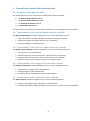
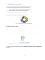
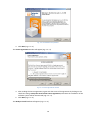
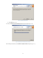
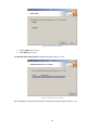
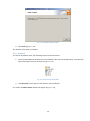
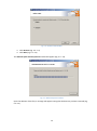
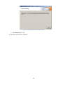
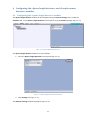
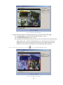
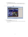
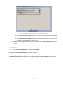
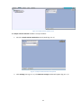
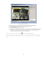
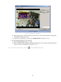
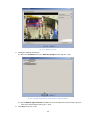
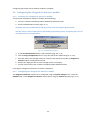
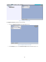
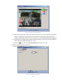
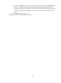
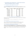
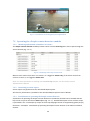
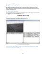
AxxonSoft «Intellect» software system Detector Pack: User’s Manual Version 2.4 Moscow 2014 1 Contents CONTENTS ......................................................................................................................................... 2 1 2 INTRODUCTION.......................................................................................................................... 4 1.1 General information ........................................................................................................... 4 1.2 Purpose of the document .................................................................................................... 4 1.3 Purpose of the detector pack .............................................................................................. 4 SOFTWARE AND HARDWARE REQUIREMENTS ............................................................................ 5 2.1 Computer and operating system requirements .................................................................... 5 2.2 Camera requirements ......................................................................................................... 5 2.2.1 2.2.2 2.2.3 2.2.4 2.2.5 Camera requirements for the Queue length detector module ............................................ 5 Camera requirements for the People counter detector module .......................................... 5 Camera requirements for the Tracker module ..................................................................... 6 Camera requirements for the Stopped car detector module ............................................... 6 Camera requirements for the Glow detection module ........................................................ 6 3 STAFFING REQUIREMENTS ......................................................................................................... 6 4 GENERAL DESCRIPTION OF THE DETECTOR PACK ......................................................................... 8 5 4.1 Structure of the detector pack ............................................................................................. 8 4.2 Functionality of the «Queue length detector» module ......................................................... 8 4.3 Functionality of the «People counter detector» module ...................................................... 8 4.4 Functionality of the «Stopped car detector» module ........................................................... 8 4.5 Functionality of the «Glow detection» module .................................................................... 8 INSTALLING THE DETECTOR PACK ............................................................................................... 9 5.1 General information on installing the detector pack ............................................................ 9 5.2 Installing the detector pack ................................................................................................. 9 5.2.1 5.2.2 5.2.3 5.2.4 6 Description of the detector pack installation files ................................................................ 9 Installation ............................................................................................................................. 9 Repair ..................................................................................................................................12 Removal ...............................................................................................................................14 CONFIGURING THE «QUEUE LENGTH DETECTOR» AND «PEOPLE COUNTER DETECTOR» MODULES 17 6.1 Configuring the «Queue length detector» module ............................................................. 17 6.2 Configuring the «People counter detector» module ........................................................... 20 6.3 Configuring the «Stopped car detector» module ................................................................ 25 6.3.1 6.3.2 6.4 Licensing the «Stopped car detector» module ...................................................................25 Configuring the «Stopped car detector» module ...............................................................25 Configuring the «Glow detection» module ........................................................................ 28 2 7 OPERATING THE «QUEUE LENGTH DETECTOR», «PEOPLE COUNTER DETECTOR» MODULES AND «STOPPED CAR DETECTOR» MODULES ............................................................................................. 33 7.1 Operating the «Queue length detector» module................................................................ 33 7.1.1 7.1.2 7.1.3 7.2 Operating the «People counter detector» module ............................................................. 34 7.2.1 7.2.2 7.2.3 8 Obtaining traffic information in the area of interest ..........................................................33 Generating a report on the traffic in the area of interest ...................................................33 Visualization of operating the Queue length detector .......................................................33 Obtaining information on number of visitors .....................................................................34 Generating a visitor report ..................................................................................................34 Visualization of operating the People counter detector .....................................................34 7.3 Operating the «Stopped car detector» module .................................................................. 35 7.4 Operating the «Glow detection» module........................................................................... 35 APPENDIX 1. DEBUG WINDOW ................................................................................................. 37 8.1 General information ......................................................................................................... 37 8.2 Start the debug window .................................................................................................... 37 8.3 Interface of debug window ............................................................................................... 38 3 1 Introduction 1.1 General information No part of this publication may be reproduced or transmitted in any way or in any form without the prior written consent of AxxonSoft. The document contains information that is current at the time of publication. The document may be changed by AxxonSoft without prior notice to other parties. 1.2 Purpose of the document The Intellect software system – Detector pack: Operator’s Manual contains the information necessary to install and operate the additional software modules that are part of the Intellect software system detector pack. The structure of this document allows the user to skim the information contained on the detector pack and to select, depending on the level of training, topics of interest for a more detailed study. Chapters in the manual - or the informational or reference content – each have their own underlying structure. The Introduction Chapter is intended as a general introduction to this document. The chapter on Software and hardware requirements states the requirements for computers in which the applicable modules that are part of the detector pack will be installed. Requirements for staff working with modules comprising the detector pack are provided in the Staffing requirements chapter. The chapter on the General description of the detector pack describes the modules comprising the detector pack. Recommendations for users and administrators to install, repair and remove the detector pack are described in detail in the chapter on Installing the detector pack. Information on configuring the Queue length detector, the People counter detector, Stopped car detector and the Glow detection modules is provided in the chapter on Configuring the “Queue length detector”, “People counter detector”, “Stopped car detector” and “Glow detection” modules. Information on operating the Queue length detector, the People counter detector, Stopped car detector and the Glow detection modules is provided in the chapter on Operating the “Queue length detector”, “People counter detector”, “Stopped car detector” and “Glow detection” modules. 1.3 Purpose of the detector pack The following detector pack modules are intended for integration and use with Intellect: 1. 2. 3. 4. Queue length detector. People counter detector. Stopped car detector. Glow detection. The installation and functionality of these modules are shown in the appropriate sections (see the chapter on the General description of the detector pack). 4 2 Software and hardware requirements 2.1 Computer and operating system requirements The computer and operating system requirements for the modules that are part the detector pack correspond to the same requirements for that of Intellect (see the Intellect system Administrator’s Manual). 2.2 Camera requirements Note. In general, the requirements listed in 2.2.1 - 2.2.4 sections are not mandatory. However, if these requirements are not met, the accuracy of the detector decreases. The remaining camera requirements for the detector pack modules correspond to similar requirements for Intellect software. 2.2.1 Camera requirements for the Queue length detector module The requirements for the cameras that will work with the Queue length detector module are listed in the Table 2.2—1. Table 2.2—1 Camera requirements for the Queue length detector module Camera Lighting Scene and camera angle Objects image Resolution: 720х576 (CIF4), using of 360х288 (CIF1) is acceptable; oversize images are reduces until CIF4. Fps: not less than 6 Color: analytics works with grey and color images. Camera must be rigidly fixed. The best working of detection is archived at medium lighting. Response to low (night) or over (flashing) lighting the quality of procedure working can be reduced. Sharp changes of lighting can lead to short-time invalid analytics working. The best position – camera “looks” to the scene vertically down. The better this requirement, the carefully the received estimation. Sizes of camera field of view: 3x3m is minimal (6x6 people), 4x4m is optimal (8x8 people), 8x8m is maximal (16x16 people). Background is static and is not changed sharply. Analytics can work inappropriately on specular surfaces and in case of sharp shadows from moved objects. Analytics can work inappropriately in case of in the camera field of view there are periodic movements of background objects (trees, working TV, etc.) Image quality: the image is to be clear, without visible defects from reducing procedure. Available size of a person: the area of a rectangle around the person as a percentage of the picture area is between 0.25% and 10%. 2.2.2 Camera requirements for the People counter detector module The requirements for the cameras that will work with the People counter detector module are listed in the Table 2.2—2. Table 2.2—2 Camera requirements for the People counter detector module Camera Lighting Scene and camera angle Resolution: 720х576 (CIF4), using of 360х288 (CIF1) is acceptable. Resolution zoom-in over CIF4 is not improve the quality of recognizing procedure. Fps: 25. Color: only color camera can be in use. Camera must be rigidly fixed. The best working of detection is archived at medium lighting. Response to low (night) or over (flashing) lighting the quality of procedure working can be reduced. Sharp changes of lighting can lead to short-time invalid analytics working. The best position – camera “looks” to the scene vertically down. The better this requirement, the carefully the received estimation. Sizes of camera field of view: 2x2m is minimal, 4x4m is optimal (8x8 people). 5 Objects image Other: Background is static and is not changed sharply. In the recognized are there no moving objects except of people. Analytics can work inappropriately on specular surfaces and in case of sharp shadows from moved objects. Analytics can work inappropriately in case of in the camera field of view there are periodic movements of background objects (trees, working TV, etc.) People occulting by static objects is to be minimal (by columns, trees etc.). Image quality: the image is to be clear, without visible defects from reducing procedure. Available size of a person: the area of a rectangle around the person as a percentage of the picture area is between 10% and 60%. People shouldn’t move by continuous flow, by groups by several people are counted properly. 2.2.3 Camera requirements for the Tracker module The requirements for the cameras that will work with the Tracker module are listed in the Table 2.2—3. Table 2.2—3 Camera requirements for the Tracker module Camera Lighting Scene and camera angle Objects image Resolution: not less than 320х240. Fps: not less than 6. Color: analytics works with grey and color images. Camera must be rigidly fixed. The best working of detection is archived at medium lighting. Response to low (night) or over (flashing) lighting the quality of procedure working can be reduced. Sharp changes of lighting can lead to short-time invalid analytics working. Moving objects in the video image should be visually distinguishable. Background is static and is not changed sharply. People occulting by static objects is to be minimal (by columns, trees etc.). Analytics can work inappropriately on specular surfaces and in case of sharp shadows from moved objects. Analytics can work inappropriately in case of long one-color objects Line sizes of objects on the image shouldn’t be less than 2% from the frame size. Line sizes are not be more than 25%. Speed of objects moving on the image is not to be less than 1 pixel by second. 2.2.4 Camera requirements for the Stopped car detector module The requirements for the cameras that will work with the Stopped car detector module are follows: The camera must be rigidly fixed. Cars in the video image should be visually distinguishable. Camera “looks” to the scene vertically down. Available car size is from 0.1 to 0.8 from the size of recognizing area. 2.2.5 Camera requirements for the Glow detection module The requirements for the cameras that will work with the Glow detection module are follows: The camera must be rigidly fixed. Light sources in the video image should be visually distinguishable. The camera is pointed to the area where all light sources are located (ideally, the optical axis of the camera is pointed strictly perpendicularly to this area). 3 Staffing requirements For the use of the Intellect-based detector, there are the following roles: 1. administrator; 2. operator. 6 In particular cases a person can perform the functions of both the administrator and operator. The main duties of the administrator are: 1. upgrading, configuring and monitoring the performance of the system hardware; 2. installing, upgrading, configuring and monitoring the performance of the system and basic software; 3. installing, configuring and monitoring the application software. The administrator must have a high level of qualifications and practical experience in the implementation of the installation, configuration and administration of software and hardware used in the software package. The structure of the system provides the ability to control all functionality available by a single administrator, and also allows for the sharing of the administrative responsibility among multiple operators. The main duties of the operator are as follows: 1. work with the system’s graphical user interface; 2. optimization of the PC for the tasks needed using the functionality provided in the system. The system operator should have experience working with PC’s based on Microsoft Windows operating systems at the level of a skilled user, and easily carry out basic operations. 7 4 General description of the detector pack 4.1 Structure of the detector pack The Intellect detector pack is comprised of 4 independent software modules: 1. 2. 3. 4. The Queue length detector module. The People counter detector module. The Stopped car detector module. The Glow detection module. The basic version of Intellect includes the software platform for the installation of these modules. 4.2 Functionality of the «Queue length detector» module The Queue length detector module is designed to carry out the following functions: 1. Count the number of people waiting in line within a certain time interval. 2. Record the number of people waiting in line in a database. 3. Plot the crowding in an observed area. 4.3 Functionality of the «People counter detector» module The People counter detector module is designed to carry out the following functions: 1. 2. 3. 4. Count visitors in an observed area. Record incidence of visitor entries into an observed area in a database. Record incidence of visitor exits from an observed area in a database. Generate reports in the number of visitors to an observed area. 4.4 Functionality of the «Stopped car detector» module The Stopped car detector module is designed to carry out the following functions: 1. Recognizing cars stopped in the specified area. 2. Recognizing jams in the specified area. 3. Recording Jams and Stopped cars events to the database. 4.5 Functionality of the «Glow detection» module The Glow detection module is designed to carry out the following functions: 1. Keeping track of light sources (lamps) in an observed area. 2. Record events about recognizing of light sources insertion or elimination to the database. 8 5 Installing the detector pack 5.1 General information on installing the detector pack The installation of the detector pack takes place in the following order: 1. Install Intellect (see the Intellect system Administrator’s Manual). 2. Install the detector pack (see the chapter on Installation). 5.2 Installing the detector pack 5.2.1 Description of the detector pack installation files Detector pack installation files on CD-ROM (see Fig. 5.2—1). Fig. 5.2—1 CD-ROM with the detector pack installation files The installation files contain the installation program and the necessary software components to install the detector pack on the computer. Only an administrator can install the detector pack. 5.2.2 Installation To install the detector pack, the following steps must be carried out: 1. Insert the CD-ROM with the detector pack installation files into the CD/DVD drive. A window will open showing the contents of the disc (Fig. 5.2—2) Fig. 5.2—2 Contents of the CD-ROM 2. Run Setup.exe, which will start the detector pack installation. As a result, a window will appear with the message Welcome to the Detector Pack v.1.2.0 Setup Wizard (Fig. 5.2—3). 9 Fig. 5.2—3 Installation setup window 3. Click Next (Fig. 5.2—3). The License agreement window will appear (Fig. 5.2—4). Fig. 5.2—4 License agreement window 4. After reading the license agreement, agree with the terms of the agreement by clicking on the check box stating I accept the terms of the License agreement, otherwise the installation of the software system will be discontinued (Fig. 5.2—4). 5. Click Next (Fig. 5.2—4). The Ready to install window will appear (Fig. 5.2—5). 10 Fig. 5.2—5 Ready to install window 6. Click Install (Fig. 5.2—5). As a result, the Detector pack installation process window will appear (Fig. 5.2—6) Fig. 5.2—6 Detector pack installation process window After installing all components, the Installation complete window will appear (Fig. 5.2—7) 11 Fig. 5.2—7 Installation complete window 7. Click Finish (Fig. 5.2—7). The detector pack installation in complete. 5.2.3 Repair To repair the detector pack, the following steps must be carried out: 1. Insert the CD-ROM with the detector pack installation files into the CD/DVD drive. A window will open showing the contents of the disc (Fig. 5.2—8) Fig. 5.2—8 Contents of the CD-ROM 2. Run Setup.exe, which will start the detector pack installation. As a result, the Select action window will appear (Fig. 5.2—9). 12 Fig. 5.2—9 Select action window 3. Select Repair (Fig. 5.2—9). 4. Click Next (Fig. 5.2—9). The Detector pack repair process window will appear (Fig. 5.2—10). Fig. 5.2—10 Repair process window After installing all components, the Repair complete window will appear (Fig. 5.2—11). 13 Fig. 5.2—11 Repair complete window 5. Click Finish (Fig. 5.2—11). The detector pack repair is complete. 5.2.4 Removal To remove the detector pack, the following steps must be carried out: 1. Insert the CD-ROM with the detector pack installation files into the CD/DVD drive. A window will open showing the contents of the disc (Fig. 5.2—12). Fig. 5.2—12 Contents of the CD-ROM 2. Run Setup.exe, which will start the detector pack installation. As a result, the Select action window will appear (Fig. 5.2—13). 14 Fig. 5.2—13 Select action window 3. Click Remove (Fig. 5.2—13). 4. Click Next (Fig. 5.2—13). The Detector pack removal process window will appear (Fig. 5.2—14). Fig. 5.2—14 Removal process window Upon the deletion of the files, a message will appear stating that the detector pack was removed (Fig. 5.2—15). 15 Fig. 5.2—15 Detector pack removal complete window 5. Click Finish (Fig. 5.2—15). The detector pack removal is complete. 16 6 Configuring the «Queue length detector» and «People counter detector» modules 6.1 Configuring the «Queue length detector» module The Queue length detector module can be configured using the System settings menu, under the Hardware tab, on the Queue Length Detection control panel, using the Camera settings (Fig. 6.1—1). Fig. 6.1—1 Queue Length Detection menu The Queue length detector module is set up as follows: 1. Go to the Queue Length Detection control panel (Fig. 6.1—2). Fig. 6.1—2 Queue Length Detection control panel 2. Click Settings (see Fig. 6.1—2). The Detector settings window will appear (Fig. 6.1—3). 17 Fig. 6.1—3 Detector settings window 3. Specify the area of interest and the approximate size of people in the video image: 3.1 Click Stop video to capture the video image (see Fig. 6.1—3, 1). 3.2 Click Area of interest (see Fig. 6.1—3, 2). 3.3 Using the left mouse button select the four corners of the area on the captured video image (see Fig. 6.1—3, 3) to be analyzed (Fig. 6.1—4, 1). Only one area may be so designated. If a second area is specified, then the first area will be deleted. Upon selection of the area the remaining part of the video image will be dimmed. Note. To remove a selected area, click the next to the Area of interest button. Fig. 6.1—4 Setting area of interest 18 3.4 Click Person size (see Fig. 6.1—4, 2). 3.5 On the captured video image (see Fig. 6.1—4, 1) specify the approximate size of a person. To do this use the left mouse button to specify a rectangular area (Fig. 6.1—5, 1). Note. To remove the person size, click the next to the Person size button. Fig. 6.1—5 Specify person size 4. Set the module parameters: 4.1 Go to the Parameters tab (see Fig. 6.1—5, 2). 4.2 Set the detection sensitivity field in a range from 0 to 1 with up to two decimal places (Fig. 6.1—6, 1). 19 Fig. 6.1—6 Configuring the Queue length detector module parameters 4.3 In the Period of activity sensing field, enter a time period in seconds for counting the number of persons in the observed area (see Fig. 6.1—6, 2). 4.4 Set the Reduce large resolution checkbox to create and process the new frame consist of even lines of initial frame (see Fig. 6.1—6, 3). 5. Click OK to save changes and return to the control panel of the Queue length detector (see Fig. 6.1—6, 4). Note. To return to the control panel of the Queue length detector without saving changes, click Cancel (see Fig. 6.1—6, 5). 6. On the Queue length detector control panel, click Apply. Configuring the Queue length detector module is complete. 6.2 Configuring the «People counter detector» module The People counter detector module can be configured using the System settings menu, under the Hardware tab, on the People counter detector control panel, using the Camera settings (Fig. 6.2—1). 20 Fig. 6.2—1 People counter detector menu The People counter detector module is set up as follows: 1. Go to the People Counter Detection control panel (Fig. 6.2—2). Fig. 6.2—2 People counter detector control panel 2. Click Settings (see Fig. 6.2—2). The Detector settings window will appear (Fig. 6.2—3). 21 Fig. 6.2—3 Detector settings window 3. Specify the area of interest and the approximate size of people in the video image: 3.1. Click Stop video to capture the video image (see Fig. 6.2—3, 1). 3.2. Click Area of interest (see Fig. 6.2—3, 2). 3.3. Using the left mouse button select the four corners of the area on the captured video image (see Fig. 6.2—3, 3) to be analyzed (Fig. 6.2—4). Only one area may be so designated. If a second area is specified, then the first area will be deleted. Note 1. To remove a selected area, click the next to the Area of interest button. Note 2. The area of interest is divided into two sections - 1 and 2. If an object moves from sector 1 to sector 2, it is logged as the entry of a visitor; if the visitor moves from sector 2 to sector 1, it is logged as an exit. 22 Fig. 6.2—4 Setting the area of interest 3.4. Set the desired size, shape and position of the sectors in the area of interest by moving their boundaries (see Fig. 6.2—4, 1). 3.5. If you want to swap sectors 1 and 2, click Change sectors (see Fig. 6.2—4, 2). 4. Set the approximate person size as follows: 4.1. Click on Person size (see Fig. 6.2—4, 3). 4.2. On the captured video image set the approximate person size. To do this, use the left mouse button to select a rectangular area (Fig. 6.2—5, 1). Note. To remove the person size, click the next to the Person size button. 23 Fig. 6.2—5 Specify person size 5. Setting the module parameters: 5.1. Go to the Parameters tab in the Detector settings window (Fig. 6.2—6, 1). Fig. 6.2—6 Configuring the People counter detector module parameters 5.2. Set the Reduce large resolution checkbox to create and process the new frame consist of even lines of initial frame (see Fig. 6.2—6, 2). 6. Click OK (see Fig. 6.2—6, 3). 24 Configuring the People counter detector module is complete. 6.3 Configuring the «Stopped car detector» module 6.3.1 Licensing the «Stopped car detector» module To license the «Stopped car detector» module do the following: 1. Go to the <Intellect installation folder>\Modules\IntelliVision folder. 2. Run the HardwareID.exe utility (Fig. 6.3—1). Attention! Start the HardwareID.exe utility from the name of computer Administrator. Also the utility is to be started after the full loading of operating system, specifically after start of all needed services and applications. Fig. 6.3—1 HardwareID.exe utility 3. In the Your HardwareID field the code is displayed (Fig. 6.3—1, 1). 4. Click the Copy To Clipboard button to copy the code to the clipboard (Fig. 6.3—1, 2). 5. Send the code to the manager of the ITV company and specify the number of Stopped car detectors which are planned to be used. 6. Receive the regkey.dat file from the manager of the ITV company. 7. Put the received file to the <Intellect installation folder>\Modules folder. Licensing the «Stopped car detector» module is completed. 6.3.2 Configuring the «Stopped car detector» module The Stopped car detector module can be configured using the System settings menu, under the Hardware tab, on the Stopped car detector control panel, using the Camera settings (Fig. 6.3—2). 25 Fig. 6.3—2 Stopped car detector object The Stopped car detector module is set up as follows: 1. Go to the Stopped car detector control panel (Fig. 6.3—3). Fig. 6.3—3 Stopped car detector control panel 2. Click Settings (Fig. 6.3—3). The Detection settings window will appear (Fig. 6.3—4). 26 Fig. 6.3—4 Detector settings window 3. Specify the area of interest and the approximate size of car in the video image: 3.1. Click Stop video to capture the video image (Fig. 6.3—4). 3.2. Using the left mouse button select the area on the captured video image to be analyzed (Fig. 6.3—5, 1). Only one area may be so designated. If a second area is specified, then the first area will be deleted. Fig. 6.3—5 Specify the analyzed area 27 3.3. Set the required size, shape and position of the analyzed area (Fig. 6.3—5, 1). To rotate the area, use the board dragging. To drag the area on the frame use the circle dotted line. To change the area size, use the grid points marked squares. The minimal height and size of the smallest base of trapezoid is 0.05 of the frame height. 3.4. Specify the approximate size of the vehicle by changing the size of the internal area in the bottom left corner of the main area (Fig. 6.3—5, 2). Note. The analyzed area is covered with not more than 256 detection zones corresponding to the car size. Recognition of stopped cars is performed only on that part of analyzed area which is covered by these zones. The part of analyzed area will not be covered by detection zones if the car size is much smaller than the size of analyzed area. To control the coverage area by detection zones, use the debug window (see Appendix 1. Debug window). 4. Set the module parameters: 4.1. Go to the Parameters tab of the Detection settings window (Fig. 6.3—6, 1). Fig. 6.3—6 Configuring the Stopped cars detector module parameters 4.2. In the Traffic Direction drop-down list select the direction of the vehicles moving towards the camera (Fig. 6.3—6, 2). 4.3. In the Stop duration, s field set the minimal stop duration in seconds using the up and down buttons (Fig. 6.3—6, 3). 5. Click OK (Fig. 6.3—6, 4). Configuring the Stopped car detector module is completed. 6.4 Configuring the «Glow detection» module The Glow detection module can be configured using the System settings menu, under the Hardware tab, on the Glow detection control panel, using the Camera settings (Fig. 6.4—1). 28 Fig. 6.4—1 Glow detection object The Glow detection module is set up as follows: 1. Go to the Glow Detection control panel (Fig. 6.4—2). Fig. 6.4—2 Glow detection control panel 2. Click Settings (Fig. 6.4—2). The Detection settings window will appear (Fig. 6.4—3). 29 Fig. 6.4—3 Detection settings window 3. Specify the location of lights sources in the image which are to be tracked by detection: 3.1. Click Stop video to capture the video image (Fig. 6.4—3). 3.2. On the captured video image specify areas to be analyzes (Fig. 6.4—4, 1). Click the left mouse button in the frame area and stretch it to the required size. The minimal allowed size of the analyzed area is 15х15 pixels. The maximum allowed size of the analyzed area is 200х200 pixels. Areas of interest are numbered in the order of creation starting from 1. The number of analyzed area is not limited. Adding the area at the right from the video image the corresponding button is displayed (Fig. 6.4—4, 2). 30 Fig. 6.4—4 Specify the areas of interest 3.3. Specify the required size, shape and location of sectors in the area of interest moving their borders. Selecting the area take into account that the local change of illuminance and specular surface near lamps in the area of interest can cause the false detection triggering. 3.4. To specify the area again click the button with its number in the list of areas and mark the area in the video image frame (Fig. 6.4—4, 2). 3.5. Click the button next to the Area of interest button (Fig. 6.4—4, 3). 4. Specify the glow detection sensitivity: 4.1. Go to the Parameters tab in the Detection settings window (Fig. 6.4—5, 1). Fig. 6.4—5 Sensitivity configuration 31 4.2. Using the up-down buttons enter the value of sensitivity parameter in the Sensitivity field (Fig. 6.4—5, 2). The optimal value is selected experimentally by testing detection on triggering in the required conditions. The value range is from 0 to 100. The more sensitivity the more possibility of false triggering. The less sensitivity, the more possibility of losing event. 5. Click the OK button (Fig. 6.4—5, 3). Configuring the Glow detection module is complete. 32 7 Operating the «Queue length detector», «People counter detector» modules and «Stopped car detector» modules 7.1 Operating the «Queue length detector» module 7.1.1 Obtaining traffic information in the area of interest As reported in the Event log interface at specified intervals by the Queue length detector module (Fig. 7.1—1). Fig. 7.1—1 Displaying traffic information in the area of interest Each line item contains information about the number of people in the area of interest at that moment in time (see Fig. 7.1—1). Note. For more information on working with the Event log interface, see the Intellect system Administrator’s Manual. 7.1.2 Generating a report on the traffic in the area of interest Reports on the traffic in the area of interest are generated via the web-based Report System. All necessary information is provided in the web-based Report System User’s Manual. 7.1.3 Visualization of operating the Queue length detector Visualization of operating the Queue length detector in the Monitor window can be realized with the help of user scripts on the base of Titles object (Fig. 7.1—1). Detailed description of one of these scripts is presented in the 1.7 Examples of scripts on the Jscript language section of Programming guide (Jscript) document – Example 1. Visualization of operating the Queue length detector in the Video surveillance monitor. 33 Fig. 7.1—1 Visualization of operating the Queue length detector 7.2 Operating the «People counter detector» module 7.2.1 Obtaining information on number of visitors The People counter detector module provides entries onto the Event log when visitors pass through the area of interest (Fig. 7.2—1). Fig. 7.2—1 Displaying visitor entry and exit events When a visitor moves from sector 1 to sector 2, it is logged as Visitor entry; if the visitor moves from sector 2 to sector 1, it is logged as Visitor exit. Note. For more information on working with the Event log interface, see the Intellect system Administrator’s Manual. 7.2.2 Generating a visitor report Visitor reports are generated via the web-based Report System. All necessary information is provided in the web-based Report System Users’s Manual. 7.2.3 Visualization of operating the People counter detector Visualization of operating the People counter detector in the Monitor window can be realized with the help of user scripts on the base of Titles object (Fig. 7.2—1). Detailed description of one of these scripts is presented in the 1.7 Examples of scripts on the Jscript language section of Programming guide (Jscript) document – Example 2. Visualization of operating the People counter detector in the Video surveillance monitor. 34 Fig. 7.2—1 Visualization of operating the People counter detector 7.3 Operating the «Stopped car detector» module The Stopped car detector module sends messages to the Event log when the stopped car is detected in the surveillance area (Fig. 7.3—1). Fig. 7.3—1 Displaying stopped cars events Note. For more information on working with the Event log interface, see the Intellect system Administrator’s Manual. When a traffic jam is detected, it is logged as a Traffic jam event. If a stopped car is detected in the surveillance area, it is logged as a Stopped car event. 7.4 Operating the «Glow detection» module The Glow detection module sends messaged to the Event log when the light source is detected or lost in the surveillance area (Fig. 7.4—1). 35 Fig. 7.4—1 Displaying Glow detection events When a light source is detected (enabled), it is logged as an Enabled event. If a light source is lost (disabled), it is logged as a Disabled event. The number of surveillance area from which the event received is displayed in the Add. Info column. 36 8 Appendix 1. Debug window 8.1 General information The debug window is designed to control events received from detectors registered in the system. Besides, the function of displaying the detection area above the video image received from camera is available in the debug window. 8.2 Start the debug window Start of the debug window is performed from the Windows task bar. Double click the left mouse button on the icon to start the debug window (Fig. 8.2—1). Fig. 8.2—1 Start debug window As a result the External detector window is displayed (Fig. 8.2—2). Fig. 8.2—2 «External Detector» debug window Attention! Start the debug window is possible only if the Debug mode is enabled with the help of Intellect Advanced Setup utility (Fig. 8.2—3). 37 Fig. 8.2—3 Enable Debug mode 8.3 Interface of debug window The debug window contains the interface components described in the table (Fig. 8.3—1, Table 8.3—1). 38 Fig. 8.3—1 Interface of debug window Table 8.3—1 Description of elements of debug window interface No 1 Name Description Preview area Element is designed for displaying the detection area above the video image. Besides detection area the specific detection settings are displayed: the person size for queue length detector and people counter detector; detection zones for stopped cars detector. 2 Area of Events viewing from detectors Events from detectors registered in the system are displayed in this area. 3 Area of system events viewing All system events except events from detectors are displayed in this area. 4 File menu Access to the Exit function. 5 Edit menu Access to the operations with text. 6 View menu Access to the function of displaying and hiding the status bar. 7 Clear button Clear areas of events viewing. 8 Help menu Access to the information about program. 9 Current object menu Selection of a detector settings of which are displayed in the preview area. The detector selection have an impact on the camera from which the video stream is used for displaying in the preview window. 39