1
BATTMASTER®
Advanced Wireless Battery
Monitoring System
User Manual
BATTMASTER® user manual rev. 9
Page 1/49
Table of contents
Table of contents:
1
2
3
4
5
Safety information..........................................................................................................................5
Acronyms ......................................................................................................................................6
System description ........................................................................................................................6
Features and benefits ....................................................................................................................8
Functional description ....................................................................................................................8
5.1
Measured parameters ...........................................................................................................8
5.2
Alarms and events .................................................................................................................8
5.3
Most significant data concept and acquisition intervals ..........................................................8
5.4
Internal resistance measurement...........................................................................................9
5.5
Discharge cycle count ...........................................................................................................9
5.6
User Interface ........................................................................................................................9
5.7
Data storage organization......................................................................................................9
5.8
Notifications ...........................................................................................................................9
5.9
Web server ..........................................................................................................................10
5.10 Database .............................................................................................................................11
5.11 Real Time Logging ..............................................................................................................12
5.12 Digital I/O ............................................................................................................................12
5.13 Modbus/TCP .......................................................................................................................12
6 Installation ...................................................................................................................................14
6.1
CU .......................................................................................................................................14
6.2
IDAM ...................................................................................................................................15
6.3
DAM ....................................................................................................................................15
6.4
BATTMASTER® software......................................................................................................17
7 Configuration ...............................................................................................................................17
7.1
Prerequisites .......................................................................................................................17
7.2
Connect to CU .....................................................................................................................17
7.3
System configuration ...........................................................................................................19
7.3.1
E-Mail notification ..........................................................................................................19
7.3.2
SMS notification .............................................................................................................20
7.3.3
Battery models configuration .........................................................................................20
7.3.4
CU configuration ............................................................................................................21
7.4
Configuring strings and batteries .........................................................................................22
7.4.1
Manual string add-on .....................................................................................................22
7.4.2
Manual battery add-on ...................................................................................................24
7.4.3
Automatic string add-on .................................................................................................25
7.4.4
Automatic battery add-on ...............................................................................................25
7.5
Configuration management .................................................................................................26
8 BATTMASTER® software .............................................................................................................27
8.1
CU connection .....................................................................................................................27
8.2
System configuration ...........................................................................................................27
8.3
System overview .................................................................................................................27
8.3.1
CU overview ..................................................................................................................28
8.3.2
String overview ..............................................................................................................29
8.3.3
IDAM firmware update ...................................................................................................30
8.3.4
IDAM replacement .........................................................................................................30
8.3.5
Battery overview ............................................................................................................31
8.3.6
DAM firmware update ....................................................................................................32
8.3.7
DAM replacement ..........................................................................................................33
8.3.8
Battery replacement .......................................................................................................33
8.4
Database management .......................................................................................................34
BATTMASTER® user manual rev. 9
Page 2/49
Table of contents
8.5
Data review .........................................................................................................................35
8.5.1
CU review ......................................................................................................................35
8.5.2
String review ..................................................................................................................36
8.5.3
Battery review ................................................................................................................37
8.5.4
Multiple traces view .......................................................................................................38
8.5.5
Cursor............................................................................................................................39
8.5.6
Change trace color ........................................................................................................39
8.5.7
Chart zoom ....................................................................................................................40
8.6
Help .....................................................................................................................................40
9 Events and alarms .......................................................................................................................42
10 Technical specifications ...............................................................................................................47
10.1 Dimensions..........................................................................................................................47
10.2 General Characteristics .......................................................................................................47
11 Orderable parts ...........................................................................................................................49
BATTMASTER® user manual rev. 9
Page 3/49
Disclaimer
DISCLAIMER
NEXTYS reserves the right to make changes without further notice to any products herein. NEXTYS
makes no warranty, representation or guarantee regarding the suitability of its products for any
particular purpose, nor does NEXTYS assume any liability arising out of the application or use of any
product, and specifically disclaims any and all liability, including without limitation consequential or
incidental damages. “Typical" parameters which may be provided in NEXTYS data sheets and/or
specifications can and do vary in different applications and actual performance may vary overtime. All
operating parameters, including “Typicals", must be validated for each customer application by
customer's technical experts. NEXTYS does not convey any license under its patent rights nor the
rights of others. NEXTYS products are not designed, intended, or authorized for use as components in
systems intended for surgical implant into the body, or other applications intended to support or
sustain life, or for any other application in which the failure of the NEXTYS product could create a
situation where personal injury or death may occur. Should Buyer purchase or use NEXTYS products
for any such unintended or unauthorized application, Buyer shall indemnity and hold NEXTYS and its
officers, employees, subsidiaries, affiliates, and distributors harmless against all claims, costs,
damages, and expenses, and reasonable attorney fees arising out of, directly or indirectly, any claim
of personal injury or death associated with such unintended or unauthorized use, even if such claim
alleges that NEXTYS was negligent regarding the design or manufacture of the part.
The Customer should ensure that it has the most up to date version of the document by contacting its
local NEXTYS office. This document supersedes any earlier documentation relating to the products
referred to herein. The information contained in this document is current at the date of publication. It
may subsequently be updated, revised or withdrawn.
All Trade Marks recognized. Specifications and information herein are Subject to change without
notice.
BATTMASTER® user manual rev. 9
Page 4/49
Chapter 1: Safety information
1 Safety information
The instructions in this manual are not intended as a substitute for proper training or adequate
experience in the safe operation of the equipment described. Only qualified personnel should work on
this equipment after first becoming thoroughly familiar with all warnings, safety notices, and
maintenance procedures contained herein and on the devices. The successful and safe operation of
this equipment is dependent on proper handling, installation, operation, and maintenance.
Only authorized repair or replacement parts shall be used in this equipment.
All installation instructions must be strictly followed.
Hazard statement definitions
DANGER
WARNING
CAUTION
Indicates an imminent hazardous situation which, if not avoided, will result in death
or serious injury.
Indicates an imminent hazardous situation which, if not avoided, could result in
death or serious injury.
Indicates an imminent hazardous situation which, if not avoided, may result in
minor or moderate injury
DANGER
HAZARDOUS VOLTAGE.
CAN CAUSE DEATH OR SERIOUS PERSONAL INJURY.
Batteries and battery cabinets contain potentially lethal voltages. To avoid electrical shock or burn,
turn of main and control voltages before performing installation or maintenance. Batteries are
energized even when AC power has been disconnected.
WARNING
RISK OF EXPLOSIVE GASSES.
Batteries generate explosive gasses during normal operation, and when discharged or charged.
WARNING
WHEN YOU WORK NEAR LEAD-ACID BATTERIES:
1. Someone should be within range of your voice or close enough to come to your aid if you
have an accident.
2. Have plenty of fresh water and soap nearby in case battery acid contacts skin, clothing, or
eyes.
3. Wear complete eye protection and protective clothing. Avoid touching your eyes while
working near a battery. If battery acid contacts your skin or clothing, wash immediately with
soap and water. If acid enters an eye, immediately flood the eye with running cold water for at
least 10 minutes and get medical attention as soon as possible.
4. Be extra cautious when handling metal tools around a battery. If you drop a metal tool near a
battery it might spark or create a short circuit between the battery terminals and some other
metal part. Either event may cause a dangerous electrical shock hazard, a fire, or even an
explosion.
5. Remove all personal metal items such as rings, bracelets, necklaces, and watches when
working with a lead-acid battery. A lead-acid battery can produce a short-circuited current
high enough to weld a metal ring or other piece of jewelry, causing a severe burn.
BATTMASTER® user manual rev. 9
Page 5/49
Chapter 2: Acronyms
2 Acronyms
Acronym
BM
RF
CU
DAM
IDAM
DAMs
Ri
AI
µSD
Definition
BATTMASTER® Monitoring System
Radio Frequency
Central Unit
Data Acquisition Module
I (current) Data Acquisition Module
Data Acquisition Modules (DAM and IDAM)
Internal resistance of lead acid battery
Acquisition interval
Micro Secure Digital card
3 System description
BATTMASTER® is a wireless battery monitoring system that measures and logs the voltage, internal
resistance, temperature and current of lead acid batteries (2, 6 or 12 V nominal voltage) as individual
blocks or within a battery string. It can operate as a standalone system or in conjunction with a
PC/LAN.
The modular architecture of the system has the benefit to be easily customizable to log other
parameters on request (i.e. pressure, humidity, etc.).
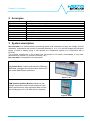
BATTMASTER® is composed of 4 components:
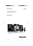
CU (Central Unit): Collects and stores the DAM and
IDAM data, manages the communication with the PC
and sends SMS/E-Mail notifications.
Figure 1: CU
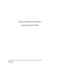
DAM (Data Acquisition Module): Measures the
voltage, temperature and internal resistance of the
battery and stores the most significant data until the
next reading by the CU. All data are time stamped.
Figure 2: DAM
BATTMASTER® user manual rev. 9
Page 6/49
Chapter 3: System description
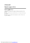
IDAM (Current Acquisition Module): Measures the
current of a battery or a string of batteries, in
conjunction with a Hall effect current clamp (factory
provided). It stores the most significant data until the
next reading by the CU. All data are time stamped.
Figure 3: IDAM
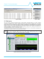
BATTMASTER® Application Software: Used to
configure and monitor the system using an USB or
Ethernet connection. It consists of a user friendly GUI
(Graphical User Interface), a data base (DB) and a
communication module.
Figure 4: Application screen
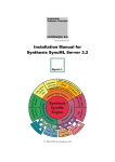
A typical system is composed by one CU, one IDAM for each string of batteries and one DAM for
each battery. A simple system composed of only one string of batteries is shown below. Each CU
supports up to 1024 (50 for lite version) DAMs and 64 IDAMs.
CU
IDAM
DAM
Battery
PC
Mobile phone
RF link
USB
10/100Mb Ethernet
Table 1: Symbols legend
Figure 5: Typical configuration
BATTMASTER® user manual rev. 9
Page 7/49
Chapter 4:
Features and benefits
4 Features and benefits
Increases safety and reliability for critical applications
Reduces the maintenance costs
Increases battery lifespan
Provides consistent information useful for battery life prediction
Eases the installation and operation
Allows integration with other systems
Ethernet connectivity allows remote monitoring
Allows automatic SMS and E-Mail notifications
It is customizable for other parameters logging (i.e. pressure, humidity, etc.)
5 Functional description
5.1 Measured parameters
Each DAM measures continuously the following battery parameters:
Voltage: Sampling rate of 10 ms.
Temperature: Sampling rate of10 ms.
Internal resistance (Ri): Periodically, at 1…168h interval, user settable.
The IDAM measures continuously for a battery or string of batteries:
Current: charge or discharge, sampling rate of 10 ms.
Discharge cycles: see §5.5.
5.2 Alarms and events
Battery parameters values that are exceeding specific thresholds (user settable) are triggering alarms
(e.g. over/under voltage, over/under temperature, etc).
The events are all the situations that produce a change of the system status (e.g. power on,
communication errors, etc).
Alarms and events are always time stamped.
See also §9.
5.3 Most significant data concept and acquisition intervals
By using a filtering algorithm the most significant values (minimum, maximum, average voltage and
temperature, last Ri measured value, discharge cycles and out of limit voltage, temperature
alarms) of all logged data within the Acquisition Interval (AI) are stored in the DAM memory and
transmitted to the CU periodically.
The user can set an Acquisition Interval (AI). AI is the interval between 2 data uploads by the DAMs
to the CU. After uploading the data, the DAMs memory is erased and a new set of significant data is
built for the following upload.
The minimum recommended value for AI is 1h, because the batteries are slowly changing systems
and there is no need of overloading the database with repetitive information. The minimum AI value is
limited automatically by the system in proportion with the number of batteries. The system guarantees
that no significant data will be lost, independently of the AI value.
In case of an alarm the DAM sends the relevant data immediately, without waiting for the pre-set AI
timing.
BATTMASTER® user manual rev. 9
Page 8/49
Chapter 5: Functional description
5.4 Internal resistance measurement
Battery internal resistance (Ri) is measured periodically by means of a controlled AC load present in
the DAM. Ri sampling interval represents the time between 2 Ri measures (user settable). Ri
measures starts only if the specific battery is not in an alarm status and it is fully charged.
5.5 Discharge cycle count
A discharge cycle is counted if the string discharge current is higher than the threshold current set for
a time longer than the threshold time set. The Thresholds are set in the String configuration as
explained in §7.4.1.
5.6 User Interface
The BATTMASTER® software application allows the user, by means of a friendly graphical interface to:
Install and configure the system.
View real time system status/measures.
Organize the collected data in a database and retrieve it in the SD card for further
analysis.
View alarms/events logs.
Export data in spreadsheets and graphs.
Execute various zoom/pan operations, set the graphical parameters.
Set up communication parameters.
BATTMASTER® software uses the port TCP 52000 (CU acting as the server). If the user PC is
not on the same LAN as the CU you may require opening this port on your firewall/router.
Contact your system administrator if necessary.
5.7 Data storage organization
The data can be stored in 2 different modes:
1. Offline: The standard logged data is stored in the SD card. When a PC (with the
BATTMASTER application running) is connected to the CU, the data can be uploaded from the
SD card and stored in the PC database (see §8.4).
2. Online: In this mode, with a PC connected to the CU and the application running, the logged
data is continuously stored to the PC database and to the SD card (see §8.3).
Use only the SD card provided with the CU kit.
The oldest data is deleted if the SD card becomes full.
5.8 Notifications
The user can configure the system to automatically send E-Mail and SMS notifications in case of an
alarm or event. Up to 2 E-Mail addresses and 3 cell phones numbers for SMS can be configured.
See §9 for a list of notifications.
The 2 images below show an example of the E-Mail and SMS received. In both cases the following
information is included in the message:
The time and date at which the event occurred.
The type of device on which the event occurred (CU, IDAM or DAM).
The position of the device in the system (e.g. 2.4 means the 4th battery on the 2nd string).
The ID of the device on which the event occurred.
The name of the event occurred.
The value (if any) associated with the event.
BATTMASTER® user manual rev. 9
Page 9/49
Chapter 5: Functional description
Figure 6: E-Mail
Figure 7:SMS
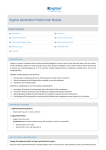
5.9 Web server
Any CU can be remotely accessed using a web browser, assuming there is a LAN / Internet
connection available at the system location and that the LAN access is allowed from the outside
world. Insert the CU IP address (or name if a DNS is configured) on the address bar of an internet
browser of your choice. On the JAVA applet the user can monitor the current status of the system as
shown on Figure 8. The applet shows the same information visible on the “System overview tab” of
the BATTMASTER® software as explained on §8.3.
The web server files are stored in the SD card provided with the CU kit. It is therefore necessary that
the SD card is inserted to the CU for the web server to work.
The CU web server uses the ports TCP 80 and 52000 (CU acting as the server). If the user
PC is not on the same LAN as the CU you may require opening these ports on your
firewall/router. Contact your system administrator if necessary.
Figure 8: Web monitoring using Chrome browser
BATTMASTER® user manual rev. 9
Page 10/49
Chapter 5: Functional description
5.10 Database
During installation of BATTMASTER® software an instance of PostgreSQL on TCP port 5432 is
installed on the PC. This instance is used by default.
Advanced user may want to use other databases type or connect to remote databases,
BATTMASTER® supports the following databases engines through JDBC:
PosgreSQL with JDBC driver “jdbc:postgresql” (http://www.postgresql.org)
MySQL with JDBC driver “jdbc:mysql”
(http://www.mysql.com/)
HyperSQL with JDBC driver “jdbc:hsqldb”
(http://hsqldb.org)
H2 with JDBC driver “jdbc:h2”
(http://www.h2database.com)
Derby with JDBC driver “jdbc:derby”
(http://db.apache.org/derby)
User can define one or more alternative JDBC connection adding a file called “config.json” in the
BATTMASTER® installation folder. For example a configuration file with two databases (first is the
default localhost PostgreSQL server and the second a remote MySQL server) would be:
{
"databases":[
{
"dbName":"Localhost PostgreSQL",
"dbConnectionString":"jdbc:postgresql://localhost/battmaster",
"dbUser":"bm",
"dbPass":"1234"
}
{
"dbName":"Remote MySQL",
"dbConnectionString":"jdbc:mysql://remote-server-name",
"dbUser":"bm",
"dbPass":"1234"
}
]
}
Where:
dbName: User friendly name shown on the startup dialog (see below)
dbConnectionString: JDBC connection string. Please refer to specific database
documentation.
dbUser: User used for login authentication
dbPass: Password used for login authentication
By default most database servers don’t allow remote connection. For example to allow
remote connection to PostgreSQL after the default installation user must add the following
lines to “pg_hba.conf” file found in the “${postgresql-installation-folder}/data” (given your
subnet is 192.168.1.1/255.255.255.0):
# TYPE
host
DATABASE
all
USER
all
ADDRESS
192.168.1.1/24
METHOD
md5
Please see http://www.postgresql.org/docs/9.4/static/auth-pg-hba-conf.html for more details
about PostgreSQL “pg_hba.conf” file.
For other database types please refer to its documentation.
BATTMASTER® user manual rev. 9
Page 11/49
Chapter 5: Functional description
In case one or more databases are defined in the file, at startup the application ask the user to select
which database to use as shown on the image below.
Figure 9: Database selection
Select the database from the dropdown list and then click OK to use the alternate server or click
cancel to use the default instance.
5.11 Real Time Logging
Measures from IDAM and DAM is collected once per Acquisition interval (see §5.3) by default.
Sometimes is useful to increase the sampling rate (for example to have a finer view of batteries
discharge during UPS test). User can increase sampling rate enabling Real Time Logging. There are
4 different ways to enable RTL:
“Start RTL” button on BATTMASTER® software (§8.3): When RTL is enabled from the
application the RTL data is sent to the PC but not stored on the SD card. User can save
this data on the PC database by using the “Start save to database” button.
Digital input 1: When RTL is enabled using this method the RTL data is saved to the SD
card automatically.
Modbus/TCP: RTL can be enabled writing 1 to the Modbus coil at address 0x5000. To
save RTL data to SD card the user must write 1 to the Modbus coil at address 0x5001.
Automatic RTL on IDAM current: In case the string current exceed a user settable
value. RTL is started on all sensors attached to the string. Once the current falls below the
threshold RTL will stop after a time specified by the user (see §7.4.1).
5.12 Digital I/O
CU as 2 digital input and 2 relay contact. The following functions are implemented:
Input 1: Enables RTL as explained on §5.11.
Input 2: Unused, available for future expansion.
Output 1: Closed when no alarm is present on the system, open otherwise.
Output 2: Unused, available for future expansion.
5.13 Modbus/TCP
CU can be accessed using Modbus/TCP on port 502. Modbus table is shown on Table 2.
IDAM address is calculated adding the string index minus 1 to the base address of the variable.
For example to read the current for the String #3:
Address= base + (IDAM index) -1 = 0x1000 + 3 – 1 = 0x1002
DAM address is calculated adding the DAM index into the string and the DAM of the previous strings
to the base address of the variable minus 1.
For example in a system with 3 strings with 4 batteries each to read the DAM #3.2 use:
Address= base + (DAM index) + (Previous String DAM count) -1 = 0x1200 + 2 + 8 – 1 = 0x1209
BATTMASTER® user manual rev. 9
Page 12/49
Chapter 5: Functional description
Name
Address
Modbus type
Function
code
Description
IDAM current
0x1000…0x103F
Input register
3,4
DAM voltage
0x1200…0x15FF
Input register
3,4
DAM temperature
0x1600…0x19FF
Input register
3,4
DAM Ri
0x1A00…0x1DFF
Input register
3,4
IDAM alarms
0x2000…0x203F
Input register
3,4
DAM alarms
0x2200…0x25FF
Input register
3,4
IDAM RTL enable
IDAM
RF
link
down
DAM RTL enable
DAM RF link down
0x4000…0x403F
0x4100…0x413F
Coil
Discrete input
1,2,5,15
1,2
0x4200…0x45FF
0x4600…0x49FF
Coil
Discrete input
1,2,5,15
1,2
Enable RTL
0x5000
Coil
1,2,5,15
Write RTL data to
SD
0x5001
Coil
1,2,5,15
IDAM measured current in steps of
0.1A
DAM measured voltage in steps of
1mV
DAM measured temperature in steps
of 0.1°C
DAM measured internal resistance in
steps of 0.1Ω
Bitfield containing the actual IDAM
alarms.
Bit0: Over charge current
Bit1: Over discharge current
Bitfield containing the actual DAM
alarms.
Bit0: Under voltage
Bit1: Over voltage
Bit3: Under temperature
Bit4: Over temperature
Bit5: Ri too high
Enables RTL for the addressed IDAM
Active if the RF link between CU and
addressed IDAM is down.
Enables RTL for the addressed DAM
Active if the RF link between CU and
addressed DAM is down.
Enable Real Time Logging. Coil
resets on Modbus disconnection.
When active the Real Time Data is
saved to the SD card. Coil resets on
Modbus disconnection.
Table 2: Modbus table
BATTMASTER® user manual rev. 9
Page 13/49
Chapter 6: Installation
6 Installation
6.1 CU
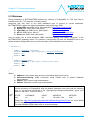
The following connection sockets are available on the CU (see Figure 10):
I/O connector: Provided with 2 INPUTS (opto isolated) and 2 OUTPUTS (dry contacts).
Out 1 is closed in case no alarm is in progress. In case of alarm the contact opens. The
other I/Os are reserved for future use.
SD card eject button: Must be pressed before removing the SD card if the CU is
powered. After pressing the button the red LED on top of the button turns OFF indicating
that the SD card can be removed safely.
SD card slot: Hosts the SD card (to be inserted following the polarity shown on the label).
10/100Mb Ethernet: Used to connect the Ethernet cable to put the system in the network.
USB port: Used to connect the USB cable from the PC to the CU. It can provide power to
the CU as an alternate to the wall mount power adapter (provided).
Important: in case of use of the USB power only (no external power supply connected) the
backup function (see below) is not active.
DC socket: Used to connect the wall mount power adapter (provided). The jack insertion
also activates the battery backup function (i.e. in case of power failure the CU is able to
run from the internal NiMH batteries for ~1.5h).
SIM card socket: Used for hosting the SIM card for the GSM communication.
GSM antenna socket: the socket standard is MMCX and it used to connect an external
antenna in case of poor signal strength. A standard GSM antenna is already present
inside the CU.
I/O
SD
Eject
10/100Mb
Ethernet
SD
DC
JACK
SIM
CARD
GSM
ANTENNA
USB
Figure 10: CU connection and sockets
Figure 11: CU top label
BATTMASTER® user manual rev. 9
Page 14/49
Chapter 6: Installation
6.2 IDAM
The IDAM must be installed as follows:
1. Select the current range on the current transducer clamp. Possible options are ±40A or
±300A.
2. Place the clamp on the conductor connecting the batteries string following the right polarity as
shown on Figure 12.
3. Plug the power adapter connector to the IDAM as shown on Figure 13. The connector has a
key to prevent reverse insertion, don’t force the connector in its socket! Carefully check that
the plug is securely connected.
4. Plug the current clamp to the IDAM as shown on Figure 13. The connector has a key to
prevent reverse insertion - don’t force the connector in its socket! Carefully check that the
plug is securely connected.
5. Plug the provided wall mount power adapter in the AC power socket. In case of automatic
configuration perform this operation later as specified in §7.4.3.
6. Calibrate clamp’s “0”: Press the “ZERO” button on the clamp with no current flowing through
the clamp and the clamp jaws closed. This operation must be performed every time the clamp
is removed or turned ON.
Figure 12: Clamp polarity
Figure 13: IDAM connections
6.3 DAM
DANGER
Due to the potentially high voltages and currents present in the system the DAM installation requires
extreme care. The installation shall be performed only by a qualified and trained technician applying
all the relevant electrical safety measures. Every DAM must be securely connected using the
provided cables only to a single battery respecting the correct polarity. When many batteries are
connected in series to form strings the total voltage can reach dangerous and potentially fatal levels.
The batteries must be disconnected from the charger and from the load during DAM installation
process. Wear complete eye protection and protective clothing.
CAUTION
To avoid damage the DAM and voiding the warranty, ensure the voltage of the battery you are using
matches the voltage rating of the DAM you are using.
The DAM can be connected to the battery thanks to 3 different terminal connections (standard) as
shown in Figure 14. The customer may order the appropriate type of cable according to its
requirements (special configurations are possible on request).
The 3 cable types are:
6.3mm Faston connection
6mm (inside diameter) ring connection
Fully isolated alligator clips
BATTMASTER® user manual rev. 9
Page 15/49
Chapter 6: Installation
Figure 14: DAM cables
Figure 15: Cable connection to the battery
Figure 16: Cable connection to the DAM
The DAM must be installed as follows (use of insulating gloves is strongly recommended):
1.
2.
3.
Fix the DAM on the battery using the provided VELCRO tape. The DAM includes an internal
temperature sensor to sense the battery ambient temperature. An optional external
temperature sensor can be provided by request.
Securely connect the DAM cable to the battery using the provided terminals. Although the
DAM is protected against reverse polarity connection please respect the polarity. The red
cable must be connected to the battery positive (+) terminal; the blue cable must be
connected to the battery negative (-) terminal.
Connect the battery cable to the DAM cable receptacle as shown in Figure 16. The connector
has a key to prevent reverse insertion - don’t force the connector in its socket. Carefully check
that the plug is securely connected. In case of automatic configuration perform this operation
later as specified in §7.4.4.
Don’t leave the DAM connected to the battery if the battery is disconnected from the charger
or out of use. Although the DAM current consumption is very low it will discharge the battery
in the long term.
BATTMASTER® user manual rev. 9
Page 16/49
Chapter 6: Installation
6.4 BATTMASTER® software
Simply run “SETUP-BATTMASTER-XX.exe” (where XX is replaced with the release number) and
follow the instructions on the screen until the end of the installation process. The installer file can be
found in the CD provided with the CU kit or it can be downloaded on NEXTYS website,
www.nextys.com.
BATTMASTER® application can be installed on any PC running Windows XP, Windows 7 (32 and
64bits) or Windows 8 (32 and 64bits).
7 Configuration
In order to run the system the user must configure it using the BATTMASTER® PC software. To
configure the system use the following procedure.
7.1 Prerequisites
1.
2.
3.
BATTMASTER® PC software should be installed on the computer (see §6.4). The installer is
provided on the CD accompanying the CU or it can be downloaded from www.nextys.com.
The CU must be turned ON and connected either with USB or LAN to the computer running
the BATTMASTER® PC software (see §6.1).
Desired voltages, current and temperatures alarm thresholds for the monitored batteries
should be known (refer to the battery manufacturer datasheet or the application specification).
7.2 Connect to CU
1.
2.
Launch the BATTMASTER® application.
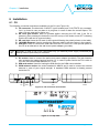
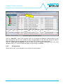
At start-up the CUs connected to the computer are discovered and shown in the “CU
connection” tab as shown on Figure 17. Ethernet discovery uses broadcast packets and
therefore only CUs present on the same network (LAN) are automatically discovered. If the
CU is not discovered automatically user should check the USB and / or LAN connection and
click on the “Discover” button on the bottom of the page. On Figure 17 the same CU is
discovered twice because it is connected on same time with USB and LAN to the same PC.
Figure 17: CU connection discovered devices
BATTMASTER® user manual rev. 9
Page 17/49
Chapter 9: Events and alarms
3.
The CU is shipped by default with a dynamic IP address (DHCP) which should fit most of the
uses. In case the CU must be run with a different setting, the user can click on the “Edit”
button to open the TCP/IP configuration dialog as shown in Figure 18. Insert the desired
values in the dialog and click on “Write to device” button to store the new setting in the CU.
Figure 18: CU connection TCP/IP configuration
4.
Connect to the CU pressing the “Connect” button. Once connected the windows title and icon
changes as shown on Figure 19. Ethernet discovery only works if the CU and the PC are on
the same LAN. In case the CU is not discoverable because not on the same LAN, the user
must write the public address or name on the field on the page bottom and click on the
“Connect to:” button.
Figure 19: CU connection
BATTMASTER® user manual rev. 9
Page 18/49
Chapter 9: Events and alarms
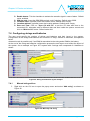
7.3 System configuration
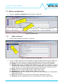
5.
Open the “System configuration” tab as shown on Figure 20.
Figure 20: System setup
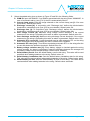
7.3.1
6.
E-Mail notification
Select E-Mail notification as shown on Figure 21.
Figure 21: E-Mail notification configuration
7.
Up to 2 E-Mail recipients can be enabled. An SMTP E-Mail account must be setup by a
provider of your choice. Select the corresponding E-Mail tab and fill in the following fields:
Enabled: Tick the checkbox to enable the E-Mail notification. Default value: disabled.
Severity level: Select “ALARMS AND EVENTS” if you want the recipient to receive
notifications for both alarms and events. Select “ALARMS ONLY” to send only notification
in case of alarm. For a list of alarms and event see §9. Default value: alarms and events.
Server: Enter the mail sever SMTP address. Default value: empty.
Sender: Enter the sender E-Mail address. Default value: empty.
Recipient: Enter recipient’s E-Mail address. Default value: empty.
Authentication: tick this checkbox if the SMTP mail server requires an authentication.
Default value: ticked.
User: Enter the user name used for the authentication. Default value: empty.
Password: Enter the password used for the authentication. Default value: empty.
BATTMASTER® user manual rev. 9
Page 19/49
Chapter 9: Events and alarms
7.3.2
8.
SMS notification
Select SMS notification as shown on Figure 22.
Figure 22: SMS notification configuration
9.
7.3.3
Up to 2 SMS recipients can be enabled. Select the corresponding SMS tab and fill in the
following fields:
Enabled: Tick the checkbox to enable the SMS notification. Default value: disabled.
Severity level: Select “ALARMS AND EVENTS” if you want the recipient to receive
notifications for both alarms and events. Select “ALARMS ONLY” to send only
notifications in case of alarm. For a list of alarms and events see §9. Default value: alarms
and events.
Phone number: Enter the SMS recipient’s phone number. Default value: empty.
Battery models configuration
10. Select Battery models as shown on Figure 23.
Figure 23: Battery's models configuration
11. Up to 8 different battery models can be described for a system, one for each row in the table
(see Figure 23). Fill in the following fields for every different battery model:
Description: Description of the battery. Default value: empty.
Vendor: Battery’s vendor name. Default value: empty.
Model: Battery’s vendor model. Default value: empty.
U max [V]: Maximum battery voltage threshold. An alarm is generated if the voltage
measured on the battery is exceeding this value. Default value: 15Volts.
BATTMASTER® user manual rev. 9
Page 20/49
Chapter 9: Events and alarms
U min [V]: Minimum battery voltage threshold. An alarm is generated if the voltage
7.3.4
measured on the battery is lower than this. Default value: 10Volts.
U nom [V]: The battery nominal voltage. Possible choices are 2V, 6V and 12V. Default
value: 12V.
Capacity [Ah]: The battery nominal capacity as specified by its datasheet. Default value:
100Ah.
Ri nom [mΩ]: The nominal battery internal resistance as specified by the battery’s vendor
datasheet. This is a reference only and may differ from the values measured by the
system. Default value: 10mΩ.
Discharge cycles: The maximum charge-discharge cycles the battery can withstand as
specified by its datasheet. Default value: 500.
Life span: The maximum life span (expressed in h) the battery can withstand as specified
by its datasheet. Default value: 60000.
T max [°C]: Maximum battery temperature threshold. An alarm is generated if the
temperature measured on the battery is exceeding this value. Default value: 50.
T min [°C]: Minimum battery temperature threshold. An alarm is generated if the
temperature measured on the battery is lower than this value. Default value: 0.
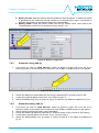
CU configuration
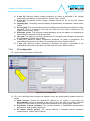
12. Select the CU as shown on Figure 24.
Figure 24: CU configuration
13. Fill in the following fields (strings and batteries count are automatically updated read only
fields):
Radio channel: Choose the desired RF channel for the system. If more than one
BATTMASTER® system is installed on the same location the user must select a different
channel for each system to avoid interference between them. Default value: channel 1.
Acquisition interval [minutes]: The interval between 2 DAM/IDAM measurements
acquisitions. Default value: 60minutes.
Ri sample interval [hours]: The interval between 2 batteries internal resistance
measurements. Default value: 24hours.
BATTMASTER® user manual rev. 9
Page 21/49
Chapter 9: Events and alarms
Enable buzzer: Tick the checkbox to activate the acoustic signal in case of alarm. Default
value: enabled.
SIM pin code: Insert the GSM SIM card pin code if existing. Default value: 0000.
Location name: (optional) insert the location name. Default value: empty.
Location address: (optional) insert the location address. Default value: empty.
Date and Time: Click on “Sync CU with PC” to set the PC date and time to the
connected CU, otherwise enter a different date and time inside the spinner control and
click on “Write to CU” button. Default value: N/A.
7.4 Configuring strings and batteries
The user must specify the number of strings and batteries and their layout in the system.
Configuration of the strings and batteries can be done in 2 ways, manual or automatic, as explained
below.
Automatic mode is possible only if an IDAM is associated to the string and a DAM to the battery.
At the end of the string and batteries configuration process the tree layout must reflect the layout of
the system. As an example on Figure 25 a system with 2 strings each composed of 4 batteries is
shown.
Figure 25: String and batteries layout example
7.4.1
1.
Manual string add-on
Right click on the CU icon to open the popup menu and select “Add string” as shown on
Figure 26.
Figure 26: Manually add string
BATTMASTER® user manual rev. 9
Page 22/49
Chapter 9: Events and alarms
2.
Select the added string icon as shown in Figure 27 and fill in the following fields:
IDAM ID: Input the IDAM ID. If no IDAM is associated with the string leave “00000000”. In
case of automatic add-on (see §7.4.3) the ID is automatically filled in.
Current clamp range: Enter the range selected on the current clamp (see §6.2 for more
information). Default value:±40A.
Discharge current [A]: In conjunction with “Discharge time” defines the discrimination
threshold for a discharge cycle (see §5.5 for more details). Default value: 5A.
Discharge time [s]: In conjunction with “Discharge current” defines the discrimination
threshold for a discharge cycle (see §5.5 for more details). Default value: 60s.
Over charge current [A]: Maximum string charge current threshold. If the current
measured on the string is exceeding this value an alarm is generated. Default value: 6A.
Over discharge current [A]: Maximum string discharge current threshold. If the current
measured on the string is exceeding this value an alarm is generated. Default value: 15A.
Automatic RTL current [A]: Current threshold used to start automatic RTL on the string
when measured current is exceeding this value. Default value: Disabled.
Automatic RTL time [sec]: Time before terminating automatic RTL on the string after the
current falls below the detection threshold. Default value: 0s.
Battery voltage variation max [%]: Every battery voltage is checked against the string
voltage average. An alarm is generated in case the difference between the average and
the battery voltage exceed this percentage. Default value: Disabled.
Default battery model: Sets the default battery used in this string. This value will be used
as default when adding batteries to the string. Default value: #1.
Default battery installation date: Sets the default battery installation date for this string.
This value will be used as default when adding batteries to the string. Default value: today.
Default battery Ri max: Sets the default battery Ri max for this string. This value will be
used as default when adding batteries to the string. Default value: automatic.
BATTMASTER® user manual rev. 9
Page 23/49
Chapter 9: Events and alarms
Figure 27: String configuration
7.4.2
1.
Manual battery add-on
Right click on the String icon to open the popup menu and select “Add battery” as shown on
Figure 28.
Figure 28: Manually add battery
2.
Select the added string icon as shown in Figure 29 and fill in the following fields:
DAM ID: Input the DAM ID. If no DAM is associated with the battery leave “00000000”. In
case of automatic add-on (see §7.4.4) the ID is automatically filled in.
Battery installation date: Input the battery installation date used for the operating time
counter. Default value: Value filled in the “Default battery installation date” field in the
parent string. (see §7.4.1).
BATTMASTER® user manual rev. 9
Page 24/49
Chapter 9: Events and alarms
Battery Ri max: Sets the battery internal resistance alarm threshold. If enabled an alarm
is generated if the measured internal resistance is exceeding this value. If automatic is
selected the system will set the threshold value automatically.
Battery model: Select the battery model from the list. Default value: Value filled in the
“Default battery model” field in the parent string. (see §7.4.1).
Figure 29: Battery configuration
7.4.3
1.
Automatic string add-on
If not done yet, click on “Start discover” button as shown in Figure 30 to put the CU in
Discovery mode. In this mode the CU checks for new IDAMs or DAMs present in the system.
Figure 30: Start discover
2.
3.
4.
7.4.4
1.
2.
3.
4.
5.
Check the IDAM to be associated with the string is powered OFF and than power it ON
A new string should appear on the tree, if not return to point 2.
Select the added string icon as shown in Figure 27 and fill in the fields as explained in §7.4.1.
Automatic battery add-on
If not done yet, click on “Start discover” button as shown in Figure 30 to put the CU in
discovery mode. In this mode the CU checks for new IDAMs or DAMs present in the system.
Select the string where the battery has to be added.
Check the DAM to be added is powered OFF and than power it ON (connect to the battery)
A new battery should appear on the tree, if not - return to point 3.
Select the added battery icon as shown in Figure 29 and fill in the fields as explained in
§7.4.2.
BATTMASTER® user manual rev. 9
Page 25/49
Chapter 9: Events and alarms
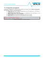
7.5 Configuration management
Configuration management is done using the buttons on the bottom of the “System Configuration”
tab as shown on Figure 31 and explained below.
Read from CU: Click to read the configuration from the connected CU. This button is
enabled only if a CU is connected.
Write to CU: Click to write and activate the configuration to the connected CU. This
button is enabled only if a CU is connected.
Read from file: Click to read the configuration from a file (xml type).
Write to file: Click to save the current configuration to file (xml type).
Figure 31: Configuration management buttons
BATTMASTER® user manual rev. 9
Page 26/49
Chapter 9: Events and alarms
8 BATTMASTER® software
There are 6 different activities that can be performed, each one related to a tab, as explained below.
Figure 32: Application tabs
8.1 CU connection
This tab is used to manage the connection with the CU. Use of this tab is explained on §7.2.
8.2 System configuration
This tab is used to configure the system. Use of this tab is explained on §7.3.
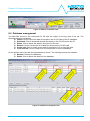
8.3 System overview
This tab shows the current system status. The different devices composing the system are
represented on the left tree where the user can select a device to view its current status. For each
device the user can choose between “Status” and “Log” view.
Figure 33: System overview tab
Status view: Depends on the device type selected and is explained in more detail below.
Log view: Shows the events and alarms history (see §9 for events and alarm description)
for each device level (system, string, battery) since the application connection to the CU
as shown on Figure 34.
BATTMASTER® user manual rev. 9
Page 27/49
Chapter 9: Events and alarms
Figure 34: System overview log tab
Click on “Start RTL” (Real Time Logging) button to log strings and batteries measurements in real
time. During RTL the CU will continue to save measurements on the SD card using the defined
acquisition interval. At any moment the user can stop RTL clicking on the button again.
Click on “Start save to database” button to start saving the logged measurements to the local
database (see §5.7). Click on the button again to stop saving to database.
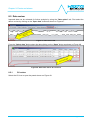
8.3.1
CU overview
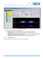
Select the CU icon on the navigation tree to show its current status.
BATTMASTER® user manual rev. 9
Page 28/49
Chapter 9: Events and alarms
Figure 35: CU overview
The following information is available on the screen:
CU info: Information about the connected CU (e.g. versions and set values)
Installation info: Information about the installation (e.g. name and address)
Statistics: Minimum, mean and maximum values for string currents, voltages and all
system batteries temperatures are shown here.
Alarms: If the corresponding alarm is active the circle becomes red, otherwise it is green.
Measurements: Graphical representation of the strings current and voltage.
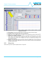
8.3.2
String overview
Select the string icon on the navigation tree to show its current status.
BATTMASTER® user manual rev. 9
Page 29/49
Chapter 9: Events and alarms
Figure 36: String overview
The following information is available on the screen:
IDAM info: Information about the IDAM associated to the selected string is shown here.
Alarms: If the corresponding alarm is active the circle becomes red, otherwise it is green.
Statistics: Minimum, mean and maximum values for batteries voltage, temperature and
internal resistance.
String info: Information about the parent string.
Charts: Select the charts shown on the measurements panel.
Measurements: Graphical representation of the measurements selected in the charts
panel.
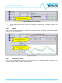
8.3.3
IDAM firmware update
IDAM firmware update is done automatically by default. For a manual update select “Update IDAM
firmware” from the popup menu as shown on Figure 41.
Figure 37: Update IDAM firmware
8.3.4
IDAM replacement
Use the following procedure to replace an IDAM:
BATTMASTER® user manual rev. 9
Page 30/49
Chapter 9: Events and alarms
1.
Right click on the string icon to activate the context menu as shown on Figure 38.
Figure 38: Replace IDAM
2.
On the opened dialog insert the ID of the new IDAM either automatically (activating the
discover option) or manually and click “OK” (see Figure 45) to confirm.
Figure 39: Replace IDAM dialog
8.3.5
Battery overview
Select the battery icon on the navigation tree to show its current status.
BATTMASTER® user manual rev. 9
Page 31/49
Chapter 9: Events and alarms
Figure 40: Battery overview
The following information is available on the screen:
DAM info: Information about the DAM associated to the selected battery.
Battery info: Generic information and alarm thresholds of the battery.
Alarms: If an alarm is active the circle becomes red, otherwise it is green.
Charts: Select the charts shown on the measurements panel.
Measurements: Graphical representation of the measurements performed on the battery.
8.3.6
DAM firmware update
DAM firmware update is done automatically by default. For a manual update select “Update DAM
firmware” from the popup menu as shown on Figure 41.
Figure 41: Update DAM firmware
BATTMASTER® user manual rev. 9
Page 32/49
Chapter 9: Events and alarms
8.3.7
DAM replacement
Use the following procedure to replace a DAM:
1. Right click on the battery icon to activate the context as shown on Figure 42Figure 38.
Figure 42: Replace IDAM
2.
On the opened dialog insert the ID of the new IDAM either automatically (activating the
discover option) or manually and click “OK” (see Figure 45) to confirm.
Figure 43: Replace DAM dialog
8.3.8
Battery replacement
Use the following procedure to replace a battery:
1. Right click on the battery icon as shown on Figure 44.
Figure 44: Replace battery
2.
On the opened dialog insert the installation date (the current date is entered by default) and
click “OK” (see Figure 45) to inform the system that a new battery has been installed.
BATTMASTER® user manual rev. 9
Page 33/49
Chapter 9: Events and alarms
Figure 45: Battery installation date
8.4 Database management
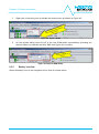
The data files stored on the connected CU SD card are visible on the top area of the tab. The
following buttons are available:
Import: Click to import the data file stored on the CU SD card to the PC database.
Download: Click to download the data file stored on the CU SD card to the PC.
Delete: Click to delete the data file from the CU SD card.
Refresh: Click to refresh the list of data files stored on the CU SD card.
Create new: Click to create a new data file used by the CU to save the data.
From local file: Click to import from a local data file to the local database.
On the bottom area of the tab the imported data is shown. The following buttons are available:
Rename: Rename the database.
Delete: Click to delete the data form the database.
Figure 46: Database management tab
BATTMASTER® user manual rev. 9
Page 34/49
Chapter 9: Events and alarms
8.5 Data review
Imported data can be reviewed for further analysis by using the “Data review” tab. First select the
data to review by clicking on the “Open data” button as shown on Figure 47.
Figure 47: Data review tab
From the “Select data” dialog select the data clicking on the “Open” button as shown on Figure 48.
Figure 48: Select the data to be reviewed
8.5.1
CU review
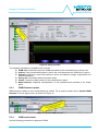
Select the CU icon to open the panels shown on Figure 49.
BATTMASTER® user manual rev. 9
Page 35/49
Chapter 9: Events and alarms
Figure 49: CU review
Plot options: Check the desired option to customize the way the chart is drawn.
CU info: Shows information about the CU configuration.
Data: Click on the “Load” button to load data for the selected time interval. Select the RTL
checkbox to load the RTL samples.
View: On the “Traces” tab check/uncheck to show/hide the data shown on the result
chart. Click on the colored spot to select the trace color. The measured values at the
cursor position are shown on the “Cursor” tab. Cursor is positioned by clicking on the
chart area (see §8.5.5).
Result: The loaded data and logs are shown. Select the “Chart” tab to view the measured
values in a chart. Select “Log” tab to view the list of alarms / events occurred during the
selected interval of time.
8.5.2
String review
Select the string icon to open the panels shown on Figure 50.
BATTMASTER® user manual rev. 9
Page 36/49
Chapter 9: Events and alarms
Figure 50: String review
Plot options: Check the desired option to customize the way the chart is drawn.
String info: Shows information about the string configuration.
Data: Click on the “Load” button to load data for the string and related batteries for the
selected time interval. Select the RTL checkbox to load the RTL samples.
View: Check/uncheck the “Traces” tab to show/hide the data shown on the result chart.
Click on the colored spot to select the trace color. The measured values at the cursor
position are shown on the “Cursor” tab. Cursor is positioned by clicking on the chart area
(see §8.5.5).
Result: The loaded data and logs are shown. Select the “Chart” tab to view the measured
values in a chart. Select “Log” tab to view the list of alarms / events occurred during the
selected interval of time.
8.5.3
Battery review
Select the battery icon to open the panels shown on Figure 51.
BATTMASTER® user manual rev. 9
Page 37/49
Chapter 9: Events and alarms
Figure 51: Battery review
Plot options: Check the desired option to customize the way the chart is drawn.
Battery info: Shows information about the battery configuration.
Data: Click on the “Load” button to load the battery data for the selected interval of time.
Click “Export DAM measures to CSV” to export the DAM measured values for the
selected interval of time to a CSV file.
View: Check/uncheck the “Traces” tab to show/hide the data shown on the result chart.
Click on the colored spot to select the trace color. The measured values at the cursor
position are shown on the “Cursor” tab. Cursor is positioned clicking on the chart area
(see §8.5.5).
Result: Shows the loaded data and logs. Select the “Chart” tab to view the measured
values in a chart. Select “Log” tab to view the list of alarms / events occurred during the
loaded interval of time.
8.5.4
Multiple traces view
The traces of various batteries in a string can be compared. This can be done by selecting the desired
ones from a popup menu available by right clicking on the trace check box.
For example, to select the “U average” for all the batteries in a string, use the following procedure:
1.
Right click on the “U average” check box on any battery of the string as shown on Figure 52.
BATTMASTER® user manual rev. 9
Page 38/49
Chapter 9: Events and alarms
Figure 52: Multiple traces selection
2.
8.5.5
On the popup menu click on “Select all U average” to select all the “U average” traces in the
string.
Cursor
Click on the chart area as shown on Figure 53 to position a cursor. The values at the cursor position
are shown on the “Cursor” tab.
Figure 53: Cursor
8.5.6
Change trace color
Click on the color spot beside the trace you want to modify. On the “Pick up a color” dialog select the
new color and click “OK” to confirm (see Figure 54).
BATTMASTER® user manual rev. 9
Page 39/49
Chapter 9: Events and alarms
Figure 54: Change trace color
8.5.7
Chart zoom
To zoom a specific area on a chart draw a rectangle starting from the top left corner of the area to be
zoomed by keeping the left mouse button pressed as shown on Figure 55.
Figure 55: Zoom area
To zoom out move the mouse from right to left keeping the left mouse button pressed.
8.6 Help
On the help tab the user can find the software version and configure the application as follows:
Check for software update: If the box is checked the application contacts the NEXTYS
update website at startup, if a new software release is available a choice is given to the
user to update the software.
Update devices automatically: If checked, the application automatically updates the
IDAM and DAM firmware if a new release if available within the installed application.
Temperature unit: Selects between Celsius or Fahrenheit unit.
BATTMASTER® user manual rev. 9
Page 40/49
Chapter 9: Events and alarms
Figure 56: Help tab
BATTMASTER® user manual rev. 9
Page 41/49
Chapter 9: Events and alarms
9 Events and alarms
ID [Hex] Name
Value
0x0001
ALARM_BUFFER_FULL
None.
Description
The DAM or IDAM was unable to send an alarm or event because the buffer was full. This should only
happen if the RF link with the CU is broken for a long period of time.
ID [Hex]
0x0002
Name
ALARM_UNDER_VOLTAGE_START
Value
Threshold voltage triggering the
alarm (U min).
Description
The DAM measured voltage drops below the “U min” set.
ID [Hex]
0x0003
Name
ALARM_UNDER_VOLTAGE_END
Value
The minimum voltage reached
during the alarm.
Description
The DAM measured voltage returns above the “U min” set.
ID [Hex]
0x0004
Name
ALARM_OVER_VOLTAGE_START
Value
Threshold voltage triggering the
alarm (U max).
Description
The DAM measured voltage exceed the “U max” set.
ID [Hex]
0x0005
Name
ALARM_OVER_VOLTAGE_END
Value
The maximum voltage reached
during the alarm.
Description
The DAM measured voltage returns below the “U max” set.
ID [Hex]
0x0006
Name
ALARM_UNDER_TEMPERATURE_START
Value
Threshold temperature
triggering the alarm (T min).
Description
The DAM measured temperature drops below the “T min” set.
ID [Hex]
a0x0007
Name
ALARM_UNDER_TEMPERATURE_END
Value
The minimum temperature
reached during the alarm.
Description
The DAM measured temperature returns above the “T min” set.
ID [Hex]
0x0008
Name
ALARM_OVER_TEMPERATURE_START
Value
Threshold temperature
triggering the alarm (T max).
Description
The DAM measured temperature exceed the “U max” set.
BATTMASTER® user manual rev. 9
Page 42/49
Chapter 9: Events and alarms
ID [Hex]
0x0009
Name
ALARM_OVER_TEMPERATURE_END
Value
The maximum temperature
reached during the alarm.
Description
The DAM measured temperature returns below the “T max” set.
ID [Hex]
0x000A
Name
ALARM_OVER_CHARGE_CURRENT_START
Value
Over charge current alarm
threshold set on IDAM.
Description
The IDAM measured charge current exceeds the threshold.
ID [Hex]
0x000B
Name
ALARM_OVER_CHARGE_CURRENT_END
Value
The maximum charge current
reached during the alarm.
Description
The DAM measured charge current drops below the alarm threshold.
ID [Hex]
0x000C
Name
ALARM_OVER_DISCHARGE_CURRENT_START
Value
Over discharge current alarm
threshold set on IDAM.
Description
The IDAM measured discharge current exceeds the threshold.
ID [Hex]
0x000D
Name
ALARM_OVER_DISCHARGE_CURRENT_END
Value
The maximum discharge
current reached during the
alarm.
Description
The DAM measured charge current drops below the alarm threshold.
ID [Hex] Name
Value
0x000E
ALARM_POWER_FAILURE_START
None.
Description
CU is running on internal NiMH batteries, no external power available.
ID [Hex] Name
0x000F
ALARM_POWER_FAILURE_END
Description
CU external power is restored.
Value
None.
ID [Hex] Name
Value
0x0010
ALARM_SD_CARD_START
None.
Description
The CU cannot write data to the SD card. The cause may be the SD is corrupted or not inserted.
ID [Hex] Name
0x00011 ALARM_SD_CARD_END
Description
The CU restores from a SD card failure.
BATTMASTER® user manual rev. 9
Value
None.
Page 43/49
Chapter 9: Events and alarms
ID [Hex]
0x0012
Name
ALARM_RI_TOO_HIGH_START
Value
Threshold internal resistance
triggering the alarm (Ri max).
Description
The measured battery internal resistance is exceed the “Ri max” set.
ID [Hex]
0x0013
Name
ALARM_RI_TOO_HIGH_END
Value
The maximum internal
resistance reached during the
alarm.
Description
The measured battery internal resistance returns below the “Ri max” set.
ID [Hex]
0x0014
Name
ALARM_VOLTAGE_UNEVEN_START
Value
The measured battery voltage
when the alarm starts.
Description
The measured battery voltage is uneven compared to the other batteries in the string.
ID [Hex]
0x0015
Name
ALARM_VOLTAGE_UNEVEN_END
Value
The measured battery voltage
when the alarm ends.
Description
The measured battery voltage is uneven compared to the other batteries in the string.
ID [Hex] Name
0x0100
EVENT_RF_LINK_DOWN_START
Description
The CU is unable to communicate with the IDAM or DAM.
Value
None.
ID [Hex] Name
0x0101
EVENT_RF_LINK_DOWN_END
Description
Communication with IDAM or DAM restored.
Value
None
ID [Hex] Name
0x0110
EVENT_STRING_DISCARGE_START
Description
String discharge cycle detected.
Value
None.
ID [Hex] Name
0x0111
EVENT_STRING_DISCARGE_END
Description
String discharge cycle finished.
Value
None.
ID [Hex] Name
Value
0x0112
EVENT_RI_NOT_MEASURED_START
None.
Description
Battery status did not allow the Ri measurement for an interval longer then 2 times the Ri acquisition
interval (see §5.4).
BATTMASTER® user manual rev. 9
Page 44/49
Chapter 9: Events and alarms
ID [Hex] Name
Value
0x0113
EVENT_RI_NOT_MEASURED_END
None.
Description
Ri measurement performed after an EVENT_RI_NOT_MEASURED_START event.
ID [Hex] Name
0x1000
EVENT_POWER_ON
Description
Triggered at any device powered on.
Value
Power on cycles count.
ID [Hex] Name
0x1001
EVENT_POWER_OFF
Description
CU powered off.
Value
None
ID [Hex] Name
0x1002
EVENT_SD_CARD_REMOVED
Description
The SD card has been removed from the CU.
Value
None
ID [Hex] Name
0x1003
EVENT_SD_CARD_INSERTED
Description
The SD card has been inserted into the CU.
Value
ID [Hex] Name
0x1004
EVENT_FS_ERROR
Description
A file system error on the SD card occurred.
Value
ID [Hex] Name
0x1006
EVENT_SD_CARD_FULL_START
Description
The SD card is used more than 90% of its capacity.
Value
ID [Hex] Name
0x1007
EVENT_SD_CARD_FULL_END
Description
The SD card is no more used more than 90% of its capacity.
Value
ID [Hex] Name
Value
0x1008
EVENT_STRING_RTL_START
Description
An automatic RTL started following a high current measured on the string.
ID [Hex] Name
0x1009
EVENT_STRING_RTL_END
Description
An automatic RTL has finished.
BATTMASTER® user manual rev. 9
Value
Page 45/49
Chapter 9: Events and alarms
BATTMASTER® user manual rev. 9
Page 46/49
Chapter 11: Orderable parts
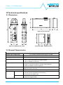
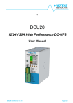
10 Technical specifications
82
10.1 Dimensions
185
150
46
81
Figure 58: CU enclosure
47
31.5
Figure 57: IDAM current clamp
56
21
Figure 59: DAM – IDAM enclosure
10.2 General Characteristics
CU
4.5…5.5VDC by external power supply or by USB
Supply input voltage range
Current consumption
0.5A max.
Backup power
2X AAA NiMh rechargeable batteries (about 1.5h of backup)
Digital inputs
- 2 x opto isolated, 5…30VDC, 10mA
- Input 1: when active Real Time Logging enables
- Input 2: available for future use
Digital outputs
- 2 x relays, 30VDC 3A max
- Output 1: is closed if no alarm is ongoing, open otherwise
- Output 2: available for future expansion
Data storage
FAT32 custom formatted microSD card, up to 4GB (> 2 years for 1000
batteries at refresh rate 0.5h)
Max. number of devices
Connectivity
64 IDAM, 1024 (50 for lite version) DAM
Ethernet
- 10/100Mb
- Used for remote configuration and monitoring
- HTTP server and SMTP client
Modbus/TCP
- Remote Monitoring
- Real Time Logging enable
BATTMASTER® user manual rev. 9
Page 47/49
Chapter 11: Orderable parts
USB2
- Full speed 12Mbit/s
- Used for remote configuration and monitoring
GSM
- Quad-Band 850/900/1800/1900MHz
- SMS alarms
RF
- 868/915MHz license free ISM baseband (3 channels settable)
- Up to 100 meters outdoor, up to 30 meters indoor
DAM
L type (2V batteries)
H type (6/12V batteries)
Battery voltage range
1.5…5.5VDC
5…18VDC
Current consumption (typical)
80mA @ 2V
30mA
RF
Battery
Measures
- 868/915MHz license free ISM baseband (3 channels settable)
- Up to 100 meters outdoor, up to 30 meters indoor
Voltage
1.5…5.5VDC, ±1.5%
Ri
1…300mΩ, ±10% or ±1mΩ
Temperature
- 20…80°C, ±2°C
5…18V, ±1.5%
Protections
-Reverse polarity (active)
-Overvoltage (passive)
Battery connection
Blade connector (Faston), ring or alligator clip; others possible on
demand
IDAM
9…18VDC(from external power supply or battery)
Supply input range
Current consumption (typical)
50mA
RF
- 868/915MHz license free ISM baseband (3 channels settable)
- Up to 100 meters outdoor, up to 30 meters indoor
Current Range
40A range:
300A range:
300A range:
Protections
-Reverse polarity (active)
-Overvoltage (passive)
0…40A, ±1.5% or ±0.4A
0…200A, ±1.5% or ±2A
200…300A, ±2.4% or ±3A
Table 3: Devices characteristics
Note: Referred values are typical. In order to improve the product specifications may change without
prior notice.
BATTMASTER® user manual rev. 9
Page 48/49
Chapter 11: Orderable parts
11 Orderable parts
P/N
6000
6010
6020
6030
Name
CU kit
DAM-H
DAM-L
IDAM kit
Description
At least one for each system is required. Includes:
1pc. CU (P/N : 6001)
1pc. 4GB micro SD card (P/N:6002)
1pc. Power Supply 5V/1A (P/N :6003)
1pc. USB cable (type A - Mini B), 1.5m long (P/N:6004)
1pc. CD with documentation and software (P/N:6005)
Voltage, temperature and internal resistance monitoring module for 5…18VDC
Voltage, temperature and internal resistance monitoring module for 1.5…5.5VDC
Current and charge cycles monitoring module. Includes:
1pc. IDAM module (P/N:6031)
1pc. current clamp max. 300A (P/N:6032)
1pc. Power Supply 12V/0.5A (P/N :6033)
6040
6050
6060
6070
TSENSE
DAMF63
DAMR6
DAMC
External temperature sensor
0.25m long DAM connection cable (Kelvin mode) with 6.3mm faston terminal
0.25m long DAM connection cable (Kelvin mode) with 6 mm ring terminal
0.25m long DAM connection cable (Kelvin mode) with alligator clip terminal
Table 4: Orderable parts
BATTMASTER® user manual rev. 9
Page 49/49