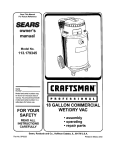
1
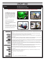
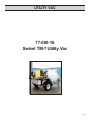
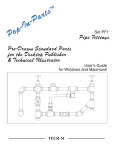
UTILITY VAC
77-000-15
SWIVEL TM-7 UTILITY VAC
77-000-16
i
PIPE & VALVE
MAINTENANCE PRODUCTS
Mod. 77-000-002 S/N:
E.H.E.H.
WACHS
COMPANIES
Wachs
Company
100600
Shepard
St.
Wheeling
Il. 60090
Knightsbridge Parkway
Lincolnshire, IL 60069
Part Number:
77-MAN-02
Revision No:
1
March ‘05
blank
UTILITY VAC
TABLE OF CONTENTS
SECTION I
SAFETY INSTRUCTIONS......................................................................................4
SECTION II
MACHINE SPECIFICATIONS................................................................................5
SECTION III
SET UP AND OPERATING PROCEDURES....................................................6-7
SECTION IV
MAINTENANCE..................................................................................................9-11
SECTION V
SCHEMATICS..................................................................................................12-19
SECTION VI
PARTS LIST......................................................................................................20-50
A. 77-000-15 Utility Vac.................................................................................20-38
B. 77-000-16 Swivel TM-7 Utility Vac..........................................................39-51
SECTION VII
ORDERING INFORMATION.................................................................................52
3
UTILITY VAC
SECTION I
SAFETY INSTRUCTIONS
The E. H. Wachs Company takes great pride in manufacturing safe, quality products with user safety a
priority.The E.H. Wachs Company recommends that all users comply with the following safety rules and
instructions when operating our equipment. For your safety and the safety of others, read and understand
these safety recommendations and operating instructions before operating.
Read the Following thoroughly
before proceeding.
1. READ THE OPERATING MANUAL!! Reading the setup and
operating instructions prior to beginning the setup procedures
can save valuable time and help prevent injury to operators or
damage to machines.
2. INSPECT MACHINE & ACCESSORIES! Prior to machine
setup physically inspect the machine and it's accessories. Look
for worn tool slides, loose bolts or nuts, lubricant leakage,
excessive rust, etc. A properly maintained machine can greatly
decrease the chances for injury.
3. ALWAYS READ PLACARDS & LABELS! All placards, labels and stickers must be clearly legible and in good condition.
Replacement labels can be purchased from the manufacturer.
4. KEEP CLEAR OF ROTATING PARTS! Keep hands, arms
and fingers clear of all rotating or moving parts. Always turn
machine off before attempting any adjustments requiring contact
with the machine or it's accessories.
5. SECURE LOOSE CLOTHING & JEWELRY! Loose fitting clothing, jewelry; long, unbound hair can get caught in the rotating
parts on machines. By keeping these things secure or removing
them you can greatly reduce the chance for injury.
6. KEEP WORK AREA CLEAR! Be sure to keep the work area
free of clutter and nonessential materials. Only allow those
personnel directly associated with the work being performed to
have access to the area if possible.
ALWAYS WEAR PROTECTIVE EQUIPMENT:
WARNING
Impact resistant eye protection
must be worn while operating or
working near this tool.
For additional information on eye and face protection, refer
to federal OSHA regulations, 29 Code of Federal Regulations, Section 1910.133., Eye and Face Protection and
American National Standards Institute, ANSI Z87.1, Occupational and Educational Eye and Face Protection. Z87.1
is available from the American National Standards Institute,
Inc., 1430 Broadway, New York, NY 10018.
CAUTION
Personal hearing protection is recommended when operating or
working near this tool.
Hearing protectors are required in high noise areas, 85
DBA or greater. The operation of other tools and equipment
in the area, reflective surfaces, process noises and resonant structures can substantially contribute to and increase
the noise level in the area. For additional information on
hearing protection, refer to federal OSHA regulations, 29
Code of Federal Regulations, Section 1910.95, Occupational Noise Exposure and ANSI S12.6 Hearing Protectors.
4
UTILITY VAC
SECTION II
MACHINE SPECIFICATIONS
VALVE MAINTENANCE SYSTEMS
Clean-out and exercise all valve boxes and valves with a complete maintenance system!
The Utility Vac can be ordered
to meet specific customer needs
or in conjunction with Wachs
Portable Valve Operators, pipe
cutters and other options such
as water jet systems can be
included.
• Clean out valve boxes fast.
Custom paint to match utilities vehicle
fleet, with integrated wand storage system.
Curbside dump vac with 180° swiveling
TM-7 valve operator.
Skid mounted unit with optional
water jet system.
TM-7 valve operator with vertical tank
Trav-L-Vac 300.
• Turn all valves safely and
easily...for emergency or routine
maintenance
• Automatically capture valve data.
Download to utility computer system
• Operate other hydraulic tools
POWER SOURCE:
20 H.P. Kohler air cooled gasoline engine (Standard)
Optional: 27 H.P. Kohler air cooled gasoline engine with heavy duty air cleaner. ( Required with pressure washer
system.)
CONTROLS:
BLOWER:
FILTRATION:
Optional
Filtration:
SPOILS TANK:
DUMPING:
PRESSURE WASHER:
TRAILERS:
FINISH:
DIMENSIONS:
Weight:
Curbside Control Panel includes: Tachometer, Hour Meter, Vacuum Break, Oil Sentry Light, Vacuum Gauge,
Dump Switch, Warning Strobe Switch and optional Pressure Washer Switch.
Belt drive, positive displacement rotary lobe impeller with 500 cfm @ 12” Hg max vacuum. 14,000 FPM air flow
through 3” hose.
3 stage Filtration consisting of a heavy material drop out debris tank, a self-contained primary and secondary filter
with 10 micron polyester reusable cartridge. All filters, washable with mild soap and water.
Cyclone pre filter to remove medium dust particles prior to final filtering. (Recommended for high dust applications)
200 liquid gallon holding capacity. Top hinged full opening 42” diameter dump door with sure seal square gasket.
6” mechanical ball shut off and 3” drain valve.
Twin cylinder electric over hydraulic dump system with the new slide and tip system for mounted applications.
This unique system moves the tank 12” to clear the bed of the truck. Automatically tilts 60°. Designed to clear the
truck bed while not compromising clearance.
(Only available with the 27 H.P. engine) 2.5 gpm, 3000 psi pressure washer with thermal overload protection. 5
gallon antifreeze tank, 125 gallon water holding tank and antifreeze/water selector valve.
Optional Trailer: (Required when purchasing a pressure washer system.) 5’x12’ with dual axle electric brakes
rated at 7000 GVW. All steel construction with diamond plate metal deck. (Pintle hitch only.)
2 part urethane.
Power Plant: 54” wide by 46” Long, Tank: 45 1/2” wide by 55” long, Total Foot Print: 55” wide by 101” long.
Overall length with pressure washer system 144”
Dry weight 4500 lbs., Tongue weight 800 lbs.
HOSE:
3” x 20’
WAND:
3” x 6 1/2’
Optional Wands:
2” x 6 1/2”, 1 1/4” 6 1/2”, 3” Excavation Wand (emulsifier).
5
UTILITY VAC
SECTION Ill
SET-UP AND OPERATION
PRE-VACUUM CHECKLIST:
1. Insure all scheduled maintenance has been properly
performed. See maintenance section in manual or refer
to maintenance decal on UTILITY VAC.
2. Insure that the hitch assembly has been properly
attached to the towing vehicle.
3. Check trailer brake lights and turn signals.
4. Check UTILITY VAC fuel level.
5. Make certain battery is charged and ready to start
UTILITY VAC engine.
6. Make certain suction hose and suction tubes are stored
on board UTILITY VAC
FIGURE 2
UTILITY VAC SET UP PROCEDURE:
1. Position UTILITY VAC near work area.
2. Connect coupling of suction hose to coupling on
vacuum inlet port. ( Figure 1)
3. Connect coupling on suction hose to coupling on
suction tube (Figure 2).
4. Once assembly of these components is complete, unit
is ready for operation.
UTILITY VAC OPERATING PROCEDURE:
FIGURE 1
FIGURE 3
6
UTILITY VAC
SECTION Ill
SET-UP AND OPERATION (information)
CLOGGED LINES:
If a clog occurs open break valve to release vacuum
pressure. Remove hose or vacuum wand from unit and
clear clog. Reassemble and close vacuum break valve to
continue clean out. FIGURE 4
Vacuum break valve
UTLITY VAC EQUIPPED WITH SWIVELING VALVE
OPERATOR
1. If your Utility Vac system is equipped with a Wachs
Valve exerciser please refer to the valve operator
operation manual supplied for the machine. The swivel
vac trailer allows the operator to position the valve
actuator quickly and effortlessly over the operating nut.
The unit can swivel a full 180 degrees to line up over
even the most difficult locations. To do this release the
two lock clamps holding the machine in location. Rotate
the machine parallel to the valve vault or nut. Release the
lock handle on the side of the Valve operator and extend
the head over the nut. Drop the key and socket onto the
nut. Once you have aligned the actuator lock both of the
clamps on the swivel plate and the clamp on the
actuator to lock the head in position,. Start valve
operation and continue until finished. (Always return
head on actuator and swivel to its travel position prior to
moving to the next valve).
FIGURE 4
4. If the unit fills with liquid to its limit, the high liquid level
float will automatically shut off the air flow. Before
restarting unit, the holding tank must be drained. If this is
not done, unit will not operate.
TM-7 Swiveling Valve Operator
7
UTILITY VAC
SECTION Ill
SET-UP AND OPERATION (cont.)
VACUUM CONTROL PANEL
FIGURE 5
UTILITY VAC DUMPING PROCEDURES:
Liquids:
1. Shut down engine.
Solids:
1. Shut down engine.
2. Position vacuum system over designated dumping
area.
3. If the material collected is primarily liquid, the holding tank
drain valve should be used to remove holding tank
contents (Figure ).
4. Once liquid has drained, from the vacuum control panel
open dump gate and remove any remaining debris.
(Figure 5)
5. Clean primary filter prior to next use. Filter can be cleaned
with only water, however, mild soap and water are
recommended if possible.
FIGURE 5
2. Position vacuum system over designated dumping area.
3. If the material collected is primarily solid, first open the
holding tank drain valve to allow any trapped liquids to
escape. Back tank up to dump position. Open tank door
and proceed to the 45 degree dump position.
4. It may be necessary to remove any remaining debris
from the holding tank manually.
5. Clean primary filter prior to next use. Filter can be cleaned
with only water, however, mild soap and water are
recommended if possible.
8
UTILITY VAC
SECTION Ill
SET-UP AND OPERATION (cont.)
OPERATING TIPS
1. While excavating water, always be sure to skin surface
with the suction tube submerge only when necessary.
2. If debris is packed in the bottom of the valve box, rotate
the suction tube assembly back and forth to break up
debris.
3. For solid debris, pouring water into the valve box greatly
speeds up debris removal.
4. If suction tube on the UTILITY VAC becomes clogged,
use a rod with a smaller diameter than the inside of tube
to assist in blockage removal.
5. For optimal efficiency, flush out suction tubes and
suction hoses prior to storage.
6. Properly performing all scheduled operators maintenance
at the designated times will insure continued peak
performance and increase the longevity of the
UTILITY VAC unit.
7. To protect your TM Valve Operator replace cover during
travel and storage. UNIT MUST BE COLD BEFORE
INSTALLING COVER. THE HEAT FROM THE MUFFLER
WILL DAMAGE THE COVER AND COULD POSSIBLY
CAUSE A FIRE).
SECTION lV
TM Valve Operator protective cover.
MAINTENANCE
FILTER REMOVAL
1. Unscrew the four wing nuts that secure the filter cover
to the filter housing. Remove cover (Figure 6).
CAUTION: DO NOT remove filter while
machine is operating. Always shut
down vacuum during maintenance.
2. Unscrew wing nut that secures filter to housing.
Remove filter (Figure 7).
FIGURE 6
FIGURE 7
9
UTILITY VAC
SECTION lV
MAINTENANCE (cont.)
BLOWER MAINTENANCE SCHEDULE
WEEKLY
CHECK OIL LEVEL:
Stop blower. Wait 5 minutes. Remove oil breather and
oil level plug. Add oil until oil runs out level holes. Replace breather and level plugs.
GREASE BEARINGS:
Grease drive end bearings with NLGI grade 2 EP grease
in a pressure gun. Force into housing through grease
fittings until clean grease emerges from relief fittings.
Wipe clean all grease from around relief fittings to prevent spraying onto drive belts.
EVERY 1,000 HOURS
CHANGE OIL.
NOTES
GENERAL MAINTENANCE SCHEDULE
DAILY
Check suction hoses for any abrasions, holes, kinks or
damaged connectors. Replace as needed.
Verify that all dump gate and filter lid camps are secured tight. Adjust if necessary.
Clean any debris from dump door seal.
Verify that all trailer and/or accessory lights are functioning properly. Repair or replace as needed.
WEEKLY
Clean holding tank from excessive debris build-up.
Check lug nuts and fasteners for tightness. Tighten as
necessary.
MONTHLY
Change oil after initial 100 hours.
Recommended oil: Mobil DTE BB, Amoco 220, Texaco
R&O 220, or equivalent .
Check blower drive belts for proper tension, frayed or
cracked condition. Adjust or replace as needed.
FILTER MAINTENANCE SCHEDULE
Check for loose piping, fittings, and connectors. Tighten
as needed.
DAILY
Check tire pressure. Fill as necessary.
Clean primary filter.
WEEKLY
Clean pre-filter
NOTES
Frequency of cleaning will increase under severe operating conditions.
All filters are washable with mild detergent and water.
Damaged filters must be replaced to prevent damage
to the blower.
10
UTILITY VAC
PRIMING THE WATER PUMP
The water pump may lose its prime if air gets into the system. Use
the following procedure to prime the pump. The system flow
switch will turn the water pump clutch on and off until all of the air
has been removed through the strainer and spray wand.
1) Fill the main water tank to at least the half-way mark with water.
2) Completely fill the anti-freeze tank with water.
3) Un-screw the clear bowl of the water strainer approximately two
turns.
4) Turn the knob on the unloader valve counter-clockwise until the
knob is just loose.
5) Turn the "Water Supply Valve" lever to the "Antifreeze/Charge
Tank" position.
6) Observe the water strainer bowl filling with water. Once the
bowl is filled with water, with no air present, hand-tighten the bowl
snug.
7) Start the gas engine and run it at medium throttle.
8) Turn the pressure washer switch to the "On" position.
9) Squeeze and hold the spray gun handle to engage the sprayer.
10) With the switch on, gradually turn the unloader valve
clockwise to increase pressure. Increase the engine speed as
needed.
11) Once pressure is increasing, turn the "Water Supply Valve"
lever to the "Tanks" position.
11
16-14 AWG FEMALE TERMINAL
FEMALECAVITY LOCK
68-143-03
68-143-04
68-143-05
68-143-08
68-143-06
12065141
12064998
12129494
12066214
12064999
2
2
3
8
4
SOLDER 428° F (220° C) MAX FOR 10 SE
COND S
SOLDER
16 AWG BK
DIN MOUNTED FUSE BLOCK
WACHS P/N: 68-173-0 2
FUSE
WACHS P/N: 68-175- XX
FIXED BRIDGE BAR
WACHS P/N: 68-173-0 4
ALL WIRING SAE J1128,TYPE GXL
-
C1
C2
NC2
NO1
NC1
NO2
+
1N5402
22
REV.
27
28
D ATE
DIMENSIONAL
.X ±.015
.X X ±.01 0
S
RUNOUT .00
FRA CTION
3
±1/32
±15 MIN.
ECO N O .
ANGLES
TOLE RANCE S
UNLESS SPECIFIED
.XX X ±.00 5
29
APR.
FLOW SWITCH
WACHS P/N: 68-188-0 0
+
10 SECOND DELAY
SOLDER
16 AWG PK
LOAD
ELECTRICAL TAPE OR SHRINK W
RAP
16 AWG GY
16 AWG OR
BK
WT
RD
BU
OR
YL
BR
PU
GY
PK
LB
TN
LG
GN
16 AWG YL
NOTE: ALL UNNOTED WIRE IS 16AWG
21
STROBE SWITCH
WACHS P/N: 68-179-0 2
16 AWG RD
PW SWITCH
WACHS P/N: 68-179-0 2
16 AWG BR
BLACK
WHITE
RED
BLUE
ORANGE
YELLOW
BRO WN
PURPLE
GRAY
PINK
LIGHT BLUE
TAN
LIGHT GREEN
GREEN
?
10
DIN MOUNT RELAY
WACHS PART #:
68-173-03
CHASSIS GROUND
16 AWG BK
FIXED BRIDGE BAR
WACHS P/N: 68-173-0 4
DIN MOUNTED TERM. BLOCK
WACHS P/N: 68-173-0 1
16 AWG BU
WIRING COLOR CODES
3-WAY SWITCH
WACHS P/N: 68-179-0 1
5
ENGINE KEYSWITCH
ACCESSORY LEAD
CLUTCH
WACHS P/N:
77-147-00
CHASSIS GRO UND
16 AWG OR
16 18 A2
16 AWG PK
3-WAY SWITCH
WACHS P/N: 68-179-0 1
1N5402
ENGINE
STARTER
LEAD
B1
A
B
C
D
DRN:
CHK:
MWG
16 AWG BK
TITLE:
31
32
33
D A TE :
(NO)
WHEELING
, IL
M A T'L :
FINISH:
D
ENGINE
OIL LEAD
L
77-ELEC
SCALE:
OIL INDICATOR LIGHT (3.4W)
WACHS P/N: 68-177-0 8
ENGINE
KILL LEAD
FUEL SHUTOFF
SOLENOID
UTILITYVAC ELECTRI
CAL SCHEM
ATIC
5/13/03
E.H.WACHSCo.
D A TE :
(C)
VACUUM SWICHGAGE (BACKSIDE)
WACHS P/N: 68-177-0 2
16 AWG BK
30
2
4
8
16
32
16 18 A2
A1 15
.3 AMP
STROBE LIGHT
WACHS P/N: 59-120-0 0
16 AWG TN
A
A1 15 B1
B
C
1
D
2
4
8
16
32
CONTROLPANEL
5
10
1N5402
1N5402
M8
16 AWG WT
-
14-12 AWG FEMALE TERMINAL
68-143-07
5
9
1N5402
1N5402
B
ST
16 AWG GN
1N5402 FLYBACK DIODE
FEMALE CONNECTOR 8 CAVITY
68-143-02
12020116
INITIATE
SWITCH
MALE CAVITY LOCK
68-143-01
12129498
5
8
STARTER
16 AWG GN
+
DESCRIPTION
MALE CONNECTOR 8 CAVITY
14-12 AWG MALE TERMINAL
16-14 AWG MALE TERMINAL
WACHS P/N
MFG. P/N
12066195
8
5
7
5
2.3 AMP
2.3 AMP
16 AWG LB
6
HPU SOLENOIDVALVES
DUMP
16 AWG BU
3
CHASSIS GROUND
2.1 AMP
C2
C1
16 AWG YL
2
2.3 AMP
2.3 AMP
16 AWG BK
QTY.
HPU SOLENOIDVALVES
LATCH
16 AWG RD
CONNECTOR ASSMEBLIE
S
CAVITY POSITION LETTER (A-H)
ELECTRI
CAL BOX
EXTERNALED
VICE
S
C4
C3
HYDRAULIC POWER UNIT
WACHS P/N: 68-132-0 0
16 AWG BR
Fx-Px
Mx-Px
4 AWG RD
4 AWG BK
MOTOR STARTER
16 AWG WT
MALE (Mx) OR FEMALE (Fx)
CONNECTOR NUMBER
BATTERY
WACHS P/N: 68-142-0 0
TO 12V ATTE
B RY
SECTION V: SCHEMATICS
77-ELECTRIC UTILITY VAC
12 AWG BK
16 AWG WT
16 AWG TN
16 AWG LB
16 AWG GY
16 AWG LG
16 AWG LG
12
BATTERY +
(4 AWG)
RELAY
CONTROL
C1
3000 PSI
RETRACT
750 PSI
C2
M
DUMP
18
3500 PSI
PART No.
x2
3
2
2
4
77-123-00
77-078-00
77-079-00
77-122-00
77-015-01
5
6
7
8
9
2
NUT, -6 (9/16"-18 THREAD
)
2
68-121-01
4
-6 ORBTORQUE 34-36 FT-L
B.
ECO NO.
DIMENSIONALTOLERANCES
±15 MIN.
ANGLES
.XXX ±.005
RUNOUT .00 3
.XX ±.010
.X ±.015
±1/32
FRACTIONS
UNLESS SPECIFIED
DATE
2" BOR
E, 18" ST
ROKE
HYDRAULIC CYLINDE
R
REV.
-8 ORBTORQUE 58-62 T.-LB.
F
-6 JICTORQUE 20-22 T.-LB.
F
-6 JICTORQUE 20-22 T.-LB.
F
-
APR.
FINISH:
WHEELING
, IL
E.H.WACHSCo.
MAT'L:
GEARHART
02-25-03
DATE:
4
DRN:
TITLE:
9/16"-18 NUTTORQUE 88 T
F.-LB.; USE THR
D.LOCK
-6 JICTORQUE 20-22 T.-LB.
F
ADAPTER
; 90 DEG -6 JIC x -8 B
OR
HYD. HOSE ASSEMB
LY (22"LONG)
HYD. HOSE ASSEMB
LY (42"LONG)
BULKHEAD TEETTING
FI ; -6 JIC
2
ADAPTER
; -6 JIC x -6 OR
B
HYD. HOSE ASSEMB
LY (106"LONG)
2
HPU
68-123-00
INSTALLATION NOTES
FILL WITH DE
XTRONAUTOMATIC TRANSMISSIONLUID
F
DESCRIPTION
77-140-00
QTY.
2
3
77-115-00
C2 C1
2
REF.No.
.86 GALLON
(3.2 LITER)
3
3
C1: 3000 PSI
C2: 750 PSI
4
8
8
D
N/A
5
7
7
SCALE:
77-HYD
AS NOTED
HYDRAULIC SCHEM
ATIC
6
5
6
8
8
1:4
9
9
SECTION V: SCHEMATICS
77-HYDRAULIC UTILITY VAC
13
BATTE
RY+
(4AWG
)
REL
AY
CONTRO
L
C2
RET
RACT
3000 PSI
750 PSI
C1
M
DUMP
9
C4
3500 PSI
UNL
ATCH
750 PSI
750 PSI
C3
.86 GALLON
(3.2 LITER)
C4: 750 PS
I
C3: 750 PS
I
LATCH
10
C4 C3 C2 C1
C1: 3000 PS
I
2 x4
C2: 750 PS
I
11
3
11
3
5
4
UNLATCH
11
12
10
LATCH
11
13
5
13
12
4
11
LATCH
11
UNLATCH
10
REV.
D A TE
EC O N O .
APR.
DIMENSIONAL
TOLE
RANCE
S
.XXX ±.00
5
ANGLES±15 MIN.
.XX ±.01
0
RUNOUT .00
3
.X ±.015
FRACTION
S ±1/32
UNLESS SPECIFIED
4
9
DATE:
FINISH:
WHEELING, IL
E.H.WACHSCo.
07/15/02
AS NOTED
SCALE:
D 77-HYD W-D
N/A
MAT'L:
7
HYDRAULIC SCHEM
ATIC W/ DOO
R
8
8
5
DRN:
4
7
9
TITLE:
WOZNIAK
6
5
6
8
8
1:4
SECTION V: SCHEMATICS
77-HYDRAULIC WITH DOOR
14
UTILITY VAC
77-HYDRAULIC WITH DOOR
REF. No.
PART No.
QTY.
68-132-00
2
68-123-00
4
3
77-140-00
2
4
68-121-01
5
77-123-00
6
7
8
DESCRIPTION
INSTALLATION NOTES
HPU
FILL WITH DEXTRON AUTOMATIC TRANSMISSION FLUID
ADAPTER; -6 JIC x -6 ORB
-6 ORB TORQUE 34-36 FT-LB.
HYD. HOSE ASSEMBLY (106" LONG)
-6 JIC TORQUE 20-22 FT.-LB.
4
NUT, -6 (9/ 16"-18 THREAD)
9/ 16" -18 NUT TORQUE 88 FT.-LB.; USE THRD. LOCK
4
BULKHEAD TEE FITTING; -6 JIC
-
77-078-00
2
HYD. HOSE ASSEMBLY (42" LONG)
-6 JIC TORQUE 20-22 FT.-LB.
77-079-00
2
HYD. HOSE ASSEMBLY (22" LONG)
-6 JIC TORQUE 20-22 FT.-LB.
77-122-00
4
ADAPTER; 90 DEG -6 JIC x -8 ORB
-8 ORB TORQUE 58-62 FT.-LB.
9
77-015-01
2
HYDRAULIC CYLINDER
2" BORE, 18" STROKE
10
68-103-00
2
HYDRAULIC CYLINDER
2" BORE, 4" STROKE
11
68-122-00
4
ADAPTER; -6 JIC x 3/ 8" MPT
3/ 8" NPT 2-3 T.F.F.T.; USE THREAD SEALANT
12
77-144-00
2
HYD. HOSE ASSEMBLY (??" LONG)
-6 JIC TORQUE 20-22 FT.-LB.
13
77-145-00
2
HYD. HOSE ASSEMBLY (??" LONG)
-6 JIC TORQUE 20-22 FT.-LB.
15
17
16
19
14
37 24
15
10
26
23
36
38
12
32
27
13
18
28
9
8
26
31
3
2
25
6
1
30 35
22
34
19
36
32
11
34
26
20
28 28
26
4
31
32
29
25
7
33
29
26
36
32
33 29
5
30 35
33
UTILITY VAC
77-PRESSURE WASHER
16
UTILITY VAC
77-PRESSURE WASHER
77- 085- 00
2
77-100- 00
3
77-127- 00
4
68-137- 00
5
68-138- 01
6
68-140- 00
7
68-141- 00
8
68-146- 00
ANTI- FREEZE TAN K
2
3- WA
9
68-168- 00
BULKHEAD FI TTING, 1/ 2" NP T
10
67-170- 00
110 GAL LON TAN K
11
68-188- 00
FLOW SWI TCH
12
68-195- 00
HOSE REEL w / 50' 3/ 8" HOSE
13
NOZZL E, .040 x 15 °
14
68-199- 00
15
68-200- 00
LANCE
-
16
68-201- 00
3/ 8" FPT S TAINLESS COUPLER
2- 3 T.F.F.T.
17
68-202- 00
3/ 8" MPT S TAINLESS NIPPL E
2- 3 T.F.F.T.
18
77-193- 10
HOSE ASSEMB LY (74" LONG)
-8 JIC TORQUE 34- 38 F T.-LB,
19
68-242- 00
20
68-193- 00
SPRAY GU N
2
DRAIN COCK
THREAD ON TO 3/ 4" PIPE ON T RAILER
SAFETY RELIEF VALVE
SET VALVE AT 4200 PSI
21
22
77-133- 00
COUPLING , 3/ 4" HOSE x - 6MP T
TORQUE TO 25 FT.- LB.
23
77-104- 00
COUPLING , 3/ 4" HOSE - 12 MPT 90° P LASTI C
-
24
77-103- 00
COUPLING , 3/ 4" HOSE x - 12 MPT P LASTI C
-
25
68-184- 02
24"
1/ 2" LOW PRESSURE PUSH ON HOS E
-
26
68-233- 00
120"
3/ 4" LOW PRESSURE PUSH ON HOS E
-
27
90-078- 59
ADAPTER , -8 MJ x -6 MPT 90 °
- 6 MP 2- 3 T.F.F.T.; -8 JIC TORQUE 34- 38 F T.- LB.
28
68-182- 03
ADAPTER , -8 MJ x -8 MPT 90 °
- 8 MP 2- 3 T.F.F.T.; -8 JIC TORQUE 34- 38 F T.- LB.
29
90-218- 75
2
ADAPTER , - 12 MJ x - 12 MPT 90 °
-12 MP 2- 3 T.F.F.T.; - 12 JIC TORQUE 78 F T.- LB.
30
68-185- 00
2
COUPLING , 1/ 2" HOSE x 1/ 2" MP T
-
31
68-183- 00
2
COUPLING , 1/ 2" HOSE x 3/ 4- 16 F JI C
-
32
68-243- 00
COUPLING , 3/ 4" HOSE x 3/ 4" MP T
-
33
68-232- 00
34
68-240- 02
35
68-240- 00
36
68-189- 01
COUPLING , 3/ 4" HOSE x 1- 1/ 16" F JI C
-
ADAPTER , - 6 MPT x - 6 MP T
- 6 MP 2-3 T.F.F.T.
2
ADAPTER , - 12 MPT x - 8 FP T
- 12 MP 2- 3 T.F.F.T.
3
TEE, -12 FPT x - 12 FPT x - 12 FP T
-
2
37
38
17
33
25 29
10
22
25
8
9
29
28
28
22
29
25
19
32
25
29
25 29
7
22
22
29
25
14
5
16
17
29
35
15
22
12
28 32
26
31
21
27
24
31
24
4
20
18
23
34
30
30 11
1
13
6
2
3
UTILITY VAC
77-SWIVELPRESSURE WASHER
18
UTILITY VAC
77-SWIVELPRESSURE WASHER
1
PUM P, 2.6 GPM ; 3000 PS I
2
77-100-00
1
CLUTCH , 12 VD C
3
77-127-00
2
BELT, A X4 1
4
68-137-00
1
UN LOADER VALVE
5
68-138-01
1
ST RAINE R
6
68-140-00
1
THERMAL VA LVE
7
68-141-00
1
8
68-146-00
1
3- WA
9
68-168-00
1
BULKHEAD FI TTING , 1/ 2" NP T
10
77-162-00
1
95 GAL LON TAN K
11
68-188-00
1
12
68-195-00
1
1
NOZZL E, .040 x 15 °
14
68-199-00
1
SPRAY GU N
15
68-200-00
1
LANC E
16
68-201-00
1
3/ 8" FPT S TAINLESS COUPLE R
17
68-202-00
1
3/ 8" MPT S TAINLESS NIPPL E
18
77-193-00
1
HOSE ASSEMB LY (50" LONG )
- 8 JIC TORQUE 34- 38 F T.- LB,
19
68-242-00
1
D RAIN COCK
THREAD ON TO 3/ 4" PIPE ON T RAILE R
20
68-193-00
1
21
68-184-02
18"
1/ 2" LOW PRESSURE PUSH ON HOS
E
22
68-233-00
164"
3/ 4" LOW PRESSURE PUSH ON HOS
E
23
90-078-59
1
24
68-182-03
25
90-128-75
26
13
FLOW SWI TCH
HOSE REEL w/ 50' 3/ 8" HOSE
SAFE TY RELIEF VA LVE
SET VALVE AT 4200 PS I
-
ADAPTER , -8 MJ x -6 MPT 90 °
- 6 MP 2- 3 T.F.F.T.; - 8 JIC TORQUE 34- 38 F T.-L B.
2
ADAPTER , -8 MJ x -8 MPT 90 °
- 8 MP 2- 3 T.F.F.T.; - 8 JIC TORQUE 34- 38 F T.-L B.
6
ADAPTER , - 12 MJ x - 12 MPT 90 °
- 12 MP 2- 3 T.F.F.T.; - 12 JIC TORQUE 78 F T.- LB.
68-185-00
1
COUPLING , 1/ 2" HOSE x 1/ 2" MP T
27
68-183-00
1
28
68-243-00
3
29
68-232-00
7
30
68-240-02
2
31
68-240-00
32
68-189-01
33
34
COUPLING , 1/ 2" HOSE x 3/ 4- 16 F JI
C
-
COUPLING , 3/ 4" HOSE x 3/ 4" MP T
COUPLING , 3/ 4" HOSE x 1- 1/ 16" F JI
C
-
ADAPTER , - 6 MPT x -6 MP T
- 6 MP 2- 3 T.F.F.T.
2
ADAPTER , -12 MPT x -8 FP T
- 12 MP 2-3 T.F.F.T.
2
TEE, -12 FPT x -12 FPT x - 12 FP T
67-171-00
1
BULKHEAD FI TTING , 3/ 4 MP T
90-098-58
1
ADAPTER , - 8 NPT (M) x - 8 NPT (M
DRILL HOLE IN
WATER TANK TO MOUN T
)
19
UTILITY VAC
SECTION VI
PARTS LIST
BILL OF MATERIALS
77-000-15
Utility Vac
20
UTILITY VAC
77-403-20 20 HP Gasoline Powerpack
Part Number
Description
Qty
77-310-00
67-006-01
67-020-00
68-130-04
68-134-00
68-158-04
68-158-46
68-158-56
68-160-03
68-160-04
68-164-00
68-165-00
68-171-01
68-172-08
68-172-09
68-173-01
68-173-02
68-173-04
68-173-05
68-173-06
68-175-05
68-177-02
68-177-08
68-179-01
68-179-02
68-194-04
77-014-01
77-058-00
68-037-13
68-037-14
68-063-41
77-058-10
77-058-11
77-058-12
77-058-13
77-058-14
77-058-15
77-058-16
77-058-17
77-058-18
77-058-19
77-058-20
77-058-21
77-058-22
77-058-23
77-058-24
77-058-25
77-058-26
77-058-29
77-058-30
90-095-12
Pha - Power Pack Base Assembly
Element, Filter
Cap,Filter Element
Bushing, 1610 X 7/8
Nipple, 3" Npt x 3" Combination Hose
Hose Clamp .21-.63"
Hose Clamp,3.75-4.63
Hose Clamp, 3" Spiral
Hose, 3" Vacuum
Hose, 4" Vacuum
Vacuum Relief
1" Grommet
Tubing, 1/4" Nylon 6
Elbow Comp. Fitting
Compression Fitting
Terminal Block
Fuse Block
Fixed Bridge Bar
Partition Plate
End Clamp
Fuse, 5 Amp
Gauge, Vacuum
Panel Light
Switch, 3-Way Moment
Switch, 2 Pos Select
Label, Dump Switch
Silencer
Wldmnt, Pwrpck Frame
Hpu Spacer
Tube, Cyclone Mount
Nipple, 3/4 x 3 SS
Base Plate
Tube, Cyclone Pilar
Plate, Pilar Support
Bar, Strainer
Bar, Drain
Angle
Din Rail
Panel, Din
Blower, Side Guard
Blower Support Bar
Plate, Fuel
Filter Plate
Filter, Gussets
Front Cross Plate
Mid Cross Plate
Rear Cross Plate
Sleeve, Fuel Retainr
Wldmnt, P.W. Mount
Mount, Pressure Wash
NUT, 1/2-13 WELD
1
1
1
1
1
2
2
7
202
22
2
4
12
1
1
8
5
1
5
2
5
1
1
1
1
1
1
1
1
1
2
1
1
1
1
1
4
1
1
2
1
1
1
2
1
1
1
1
1
1
2
21
UTILITY VAC
77-403-20 20 HP Gasoline Powerpack
Part Number
77-070-00
68-043-13
68-043-16
77-070-10
77-070-11
77-070-12
77-070-13
77-070-14
77-070-15
77-070-16
77-070-17
77-070-18
77-178-00
90-055-07
90-075-10
77-059-00
77-060-00
77-061-00
77-062-00
77-064-00
68-034-11
77-064-10
77-064-12
77-064-11
77-069-00
77-069-10
77-064-12
77-171-11
77-071-00
77-071-10
77-071-11
77-081-00
77-081-10
90-075-10
90-095-12
77-084-00
77-084-10
77-084-11
77-084-12
77-086-00
77-087-00
77-087-10
90-055-07
77-088-00
77-088-10
77-088-11
77-089-00
77-089-10
77-089-11
77-093-00
77-094-00
77-095-00
77-106-00
Description
Weldment, Filter
Bracket, Filter
Rod, Threaded
Body, Filter
Bottom, Filter
Surface, Filter Seal
Hinge, Filter
Bracket, Latch
Tube, Filter Output
Tube, Filter Inlet
Ring, Filter Guide
Tube, Filter Inlet
2" Weld On Tank Fitting
NUT, 1/4-20 WELD
NUT, 3/8-16 WELD
Panel, Vac Break
Panel, Controls
Panel Instructions
Panel, Water Drain
Wldmnt, Inlet
Elbow, 3" 90deg Shrt
Nipple, Modified
Nipple, 3" NPT x 8" Schd 40
3" Dia X 2" Tube
Wldmnt, Vac Break Inlet
Modified Nipple
Nipple, 3" NPT x 8" Schd 40
Bracket, Nipple Mounting
Weldment, Filter Door
Door, Filter
Hinge, Door
Wldmnt, Blwr Tension
Bracket, Blwr Tensioner
NUT, 3/8-16 WELD
NUT, 1/2-13 WELD
Wldmnt, Fuel Tnk Ret
Stop, Tank
Shldr, Tank Retainer
Rod, Fuel Retainer
500 Cfm Blower
Wldmnt, Engine Guard
Guard, Engine Belt
NUT, 1/4-20 WELD
Wldmnt, Blower Guard
Guard, Blower Side
Guard, Blower Front
Wldmnt, P.W. Guard
Guard, P.W. Outside
Guard, P.W. Inside
Label, Vacuum
Label, Safety
Label, Vacuum Break
Elbow, 3" Street
Qty
1
1
1
1
1
1
2
6
1
1
1
1
2
15
20
1
1
1
1
1
1
1
1
1
1
1
0.5
2
1
1
1
1
1
4
2
1
1
1
1
1
1
1
2
1
1
1
1
1
1
1
1
1
1
22
UTILITY VAC
77-403-20 20 HP Gasoline Powerpack
Part Number
77-107-00
77-110-00
77-111-00
77-116-00
77-139-00
77-141-00
77-141-10
77-141-11
77-141-12
77-142-00
77-148-00
77-202-00
77-166-10
77-166-09
77-202-10
77-203-00
90-036-97
90-055-01
90-055-52
90-067-64
90-071-07
90-071-12
90-071-17
90-075-01
90-075-10
90-075-53
90-079-90
90-091-10
90-091-41
90-151-06
90-155-52
90-155-56
90-219-01
77-313-01
17-088-00
59-033-01
59-035-00
67-051-00
68-142-00
68-158-04
68-159-25
68-177-08
77-067-00
77-092-00
77-112-01
77-113-00
77-114-00
77-132-00
77-139-00
77-181-00
77-182-00
77-183-00
77-184-00
77-185-00
77-186-00
77-191-00
77-192-00
77-131-00
Description
RodEnd, 3/8" SS
Sheave, 2/3 V6.50
Belt, 2/3vx475
Knob, Filter
1" Grommet
Weldment, Filter Inlet
Tube, Filter Inlet
3" Tube
Adapter, 4" To 3"
Diode
Seal, Filter
Weldment, Electrical Enclosure
Din, Rail
Rail, DIN 3 - 35mm x 7.5mm x 39"
Enclosure, Electrical
Mount, Cable Tie
PIN, COTTER 5/32
NUT, 1/4-20 HEX
WASHER, 1/4 SPLIT RING
BOLT, STRIPPER 5/16 X 1-1/2
HHCS, 3/8-16 X 3/4
HHCS, 3/8-16 X 1-1/4
HHCS, 3/8-16 X 1-3/4
NUT, 3/8-16 HEX
NUT, 3/8-16 WELD
WASHER, 3/8 FLAT
PIN, CLEVIS 3/8 X 1"
HHCS, 1/2-13 X 1
HHCS, 1/2-13 X 4 FL THD
HHCS, 1/4-20 X 5/8 - SS
WASHER, 1/4 SPLIT RING - SS
WASHER, #12 FLAT - SS
RING, 3/4 EXT RETAIN
Pha - 20 Hp Engine
Tank, Fuel
Kohler Ch20s
Tach / Hourmeter
Case,Battery
Battery
Hose Clamp .21-.63"
1/4" Fuel Line
Panel Light
Plate, 3-Way Cover
Label, Low Oil Press
Bushing, 1610x1-1/8"
Muffler
Muffler Guard
Clamp
1" Grommet
Nipple, 3/8 Npt X 2" Long
Nipple, 3/8 Npt X 6" Long
Elbow, 3/8 Npt
Coupling, 3/8"
Plug, 3/8"
Cap, 1-1/2" Rain
One Piece Threaded Clamp On Collar
Weldment, Muffler Elbow
Qty
3
2
1
1
2
1
1
1
1
6
1
1
1
0.25
1
4
5
2
2
1
16
4
4
6
3
24
5
2
2
13
13
13
1
1
1
1
1
1
1
2
20
1
1
1
1
1
1
1
2
1
1
1
1
1
1
0
1
23
UTILITY VAC
77-403-27
27 HP Gasoline Powerpack
Parts Number
Description
Qty
67-006-01
67-020-00
68-130-04
68-134-00
68-158-04
68-158-46
68-158-56
68-160-03
68-160-04
68-164-00
68-165-00
68-171-01
68-172-08
68-172-09
68-173-01
68-173-02
68-173-04
68-173-05
68-173-06
68-175-05
68-177-02
68-177-08
68-179-01
68-179-02
68-194-04
77-014-01
77-058-00
68-037-13
68-037-14
68-063-41
77-058-10
77-058-11
77-058-12
77-058-13
77-058-14
77-058-15
77-058-16
77-058-17
77-058-18
77-058-19
77-058-20
77-058-21
77-058-22
77-058-23
77-058-24
77-058-25
77-058-26
77-058-29
77-058-30
90-095-12
77-070-00
Element, Filter
Cap,Filter Element
Bushing, 1610 X 7/8
Nipple, 3" Npt x 3" Combination Hose
Hose Clamp .21-.63"
Hose Clamp,3.75-4.63
Hose Clamp, 3" Spiral
Hose, 3" Vacuum
Hose, 4" Vacuum
Vacuum Relief
1" Grommet
Tubing, 1/4" Nylon 6
Elbow Comp. Fitting
Compression Fitting
Terminal Block
Fuse Block
Fixed Bridge Bar
Partition Plate
End Clamp
Fuse, 5 Amp
Gauge, Vacuum
Panel Light
Switch, 3-Way Moment
Switch, 2 Pos Select
Label, Dump Switch
Silencer
Wldmnt, Pwrpck Frame
Hpu Spacer
Tube, Cyclone Mount
Nipple, 3/4 x 3 SS
Base Plate
Tube, Cyclone Pilar
Plate, Pilar Support
Bar, Strainer
Bar, Drain
Angle
Din Rail
Panel, Din
Blower, Side Guard
Blower Support Bar
Plate, Fuel
Filter Plate
Filter, Gussets
Front Cross Plate
Mid Cross Plate
Rear Cross Plate
Sleeve, Fuel Retainr
Wldmnt, P.W. Mount
Mount, Pressure Wash
NUT, 1/2-13 WELD
Weldment, Filter
1
1
1
1
2
2
7
202
22
2
4
12
1
1
8
5
1
5
2
5
1
1
1
1
1
1
1
1
1
2
1
1
1
1
1
4
1
1
2
1
1
1
2
1
1
1
1
1
1
2
1
24
UTILITY VAC
77-403-27
27 HP Gasoline Powerpack
Parts Number
Description
Qty
68-043-13
68-043-16
77-070-10
77-070-11
77-070-12
77-070-13
77-070-14
77-070-15
77-070-16
77-070-17
77-070-18
77-178-00
90-055-07
90-075-10
77-059-00
77-060-00
77-061-00
77-062-00
77-064-00
68-034-11
77-064-10
77-064-12
77-064-11
77-069-00
77-069-10
77-064-12
Bracket, Filter
Rod, Threaded
Body, Filter
Bottom, Filter
Surface, Filter Seal
Hinge, Filter
Bracket, Latch
Tube, Filter Output
Tube, Filter Inlet
Ring, Filter Guide
Tube, Filter Inlet
2" Weld On Tank Fitting
NUT, 1/4-20 WELD
NUT, 3/8-16 WELD
Panel, Vac Break
Panel, Controls
Panel Instructions
Panel, Water Drain
Wldmnt, Inlet
Elbow, 3" 90deg Shrt
Nipple, Modified
Nipple, 3" NPT x 8" Schd 40
3" Dia X 2" Tube
Wldmnt, Vac Break Inlet
Modified Nipple
Nipple, 3" NPT x 8" Schd 40
1
1
1
1
1
2
6
1
1
1
1
2
15
20
1
1
1
1
1
1
1
1
1
1
1
0.5
25
UTILITY VAC
77-403-H1 Hydraulic Powerpack
Part Number
67-006-01
67-020-00
68-130-04
68-134-00
68-158-04
68-158-46
68-158-56
68-160-03
68-160-04
68-164-00
68-165-00
68-171-01
68-172-08
68-172-09
68-173-01
68-173-02
68-173-04
68-173-05
68-173-06
68-175-05
68-177-02
68-177-08
68-179-01
68-179-02
68-194-04
77-014-01
77-058-00
68-037-13
68-037-14
68-063-41
77-058-10
77-058-11
77-058-12
77-058-13
77-058-14
77-058-15
77-058-16
77-058-17
77-058-18
77-058-19
77-058-20
77-058-21
77-058-22
77-058-23
77-058-24
77-058-25
77-058-26
77-058-29
Description
Element, Filter
Cap,Filter Element
Bushing, 1610 X 7/8
Nipple, 3" Npt x 3" Combination Hose
Hose Clamp .21-.63"
Hose Clamp,3.75-4.63
Hose Clamp, 3" Spiral
Hose, 3" Vacuum
Hose, 4" Vacuum
Vacuum Relief
1" Grommet
Tubing, 1/4" Nylon 6
Elbow Comp. Fitting
Compression Fitting
Terminal Block
Fuse Block
Fixed Bridge Bar
Partition Plate
End Clamp
Fuse, 5 Amp
Gauge, Vacuum
Panel Light
Switch, 3-Way Moment
Switch, 2 Pos Select
Label, Dump Switch
Silencer
Wldmnt, Pwrpck Frame
Hpu Spacer
Tube, Cyclone Mount
Nipple, 3/4 x 3 SS
Base Plate
Tube, Cyclone Pilar
Plate, Pilar Support
Bar, Strainer
Bar, Drain
Angle
Din Rail
Panel, Din
Blower, Side Guard
Blower Support Bar
Plate, Fuel
Filter Plate
Filter, Gussets
Front Cross Plate
Mid Cross Plate
Rear Cross Plate
Sleeve, Fuel Retainr
Wldmnt, P.W. Mount
Qty
1
1
1
1
2
2
7
202
22
2
4
12
1
1
8
5
1
5
2
5
1
1
1
1
1
1
1
1
1
2
1
1
1
1
1
4
1
1
2
1
1
1
2
1
1
1
1
1
26
UTILITY VAC
77-403-H1
Part Number
68-043-13
68-043-16
77-070-10
77-070-11
77-070-12
77-070-13
77-070-14
77-070-15
77-070-16
77-070-17
77-070-18
77-178-00
90-055-07
90-075-10
77-059-00
77-060-00
77-061-00
77-062-00
77-064-00
68-034-11
77-064-10
77-064-12
77-064-11
77-069-00
77-069-10
77-064-12
77-171-11
77-071-00
77-071-10
77-071-11
77-081-00
77-081-10
90-075-10
90-095-12
77-084-00
77-084-10
77-084-11
77-084-12
77-086-00
77-087-00
77-087-10
90-055-07
77-088-00
77-088-10
77-088-11
77-089-00
77-089-10
77-089-11
77-093-00
77-094-00
Hydraulic Powerpack
Description
Bracket, Filter
Rod, Threaded
Body, Filter
Bottom, Filter
Surface, Filter Seal
Hinge, Filter
Bracket, Latch
Tube, Filter Output
Tube, Filter Inlet
Ring, Filter Guide
Tube, Filter Inlet
2" Weld On Tank Fitting
NUT, 1/4-20 WELD
NUT, 3/8-16 WELD
Panel, Vac Break
Panel, Controls
Panel Instructions
Panel, Water Drain
Wldmnt, Inlet
Elbow, 3" 90deg Shrt
Nipple, Modified
Nipple, 3" NPT x 8" Schd 40
3" Dia X 2" Tube
Wldmnt, Vac Break Inlet
Modified Nipple
Nipple, 3" NPT x 8" Schd 40
Bracket, Nipple Mounting
Weldment, Filter Door
Door, Filter
Hinge, Door
Wldmnt, Blwr Tension
Bracket, Blwr Tensioner
NUT, 3/8-16 WELD
NUT, 1/2-13 WELD
Wldmnt, Fuel Tnk Ret
Stop, Tank
Shldr, Tank Retainer
Rod, Fuel Retainer
500 Cfm Blower
Wldmnt, Engine Guard
Guard, Engine Belt
NUT, 1/4-20 WELD
Wldmnt, Blower Guard
Guard, Blower Side
Guard, Blower Front
Wldmnt, P.W. Guard
Guard, P.W. Outside
Guard, P.W. Inside
Label, Vacuum
Label, Safety
Qty
1
1
1
1
1
2
6
1
1
1
1
2
15
20
1
1
1
1
1
1
1
1
1
1
1
0.5
2
1
1
1
1
1
4
2
1
1
1
1
1
1
1
2
1
1
1
1
1
1
1
1
27
UTILITY VAC
77-403-H1
Part Number
77-110-00
77-111-00
77-116-00
77-139-00
77-141-00
77-141-10
77-141-11
77-141-12
77-142-00
77-148-00
77-202-00
77-166-10
77-166-09
77-202-10
77-203-00
90-036-97
90-055-01
90-055-52
90-067-64
90-071-07
90-071-12
90-071-17
90-075-01
90-075-10
90-075-53
90-079-90
90-091-10
90-091-41
90-151-06
90-155-52
90-155-56
90-219-01
77-313-03
59-152-00
59-156-00
68-130-04
77-067-00
77-149-00
77-800-00
77-204-00
77-205-00
77-206-00
77-207-00
77-208-00
90-059-62
90-218-93
90-218-99
Hydraulic Powerpack
Description
Sheave, 2/3 V6.50
Belt, 2/3vx475
Knob, Filter
1" Grommet
Weldment, Filter Inlet
Tube, Filter Inlet
3" Tube
Adapter, 4" To 3"
Diode
Seal, Filter
Weldment, Electrical Enclosure
Din, Rail
Rail, DIN 3 - 35mm x 7.5mm x 39"
Enclosure, Electrical
Mount, Cable Tie
PIN, COTTER 5/32
NUT, 1/4-20 HEX
WASHER, 1/4 SPLIT RING
BOLT, STRIPPER 5/16 X 1-1/2
HHCS, 3/8-16 X 3/4
HHCS, 3/8-16 X 1-1/4
HHCS, 3/8-16 X 1-3/4
NUT, 3/8-16 HEX
NUT, 3/8-16 WELD
WASHER, 3/8 FLAT
PIN, CLEVIS 3/8 X 1"
HHCS, 1/2-13 X 1
HHCS, 1/2-13 X 4 FL THD
HHCS, 1/4-20 X 5/8 - SS
WASHER, 1/4 SPLIT RING - SS
WASHER, #12 FLAT - SS
RING, 3/4 EXT RETAIN
Pha - Hydraulic Drive
Hydraulic Motor
Motor Foot Mount
Bushing, 1610 X 7/8
Plate, 3-Way Cover
Plate, Hydraulic Motor Adapter
Blank, Hyd Motor Adapter
PILOT OPERATED RELIEF VALVE
CARTRIDGE BODY
HOSE, HYDRAULIC BYPASS
HOSE, AEROQUIP 3/4" MATCHMATE
FITTING, 3/4" JIC CRIMP
PLUG, 1/4 NPT*
ADAPTER, 3/4 ORB M X 3/4 JIC M - STRAIGHT
TEE, 3/4" JIC(M) x 3/4" NPT(M) x 3/4" JIC(M)
Qty
2
1
1
2
1
1
1
1
6
1
1
1
0.25
1
4
5
2
2
1
16
4
4
6
3
24
5
2
2
13
13
13
1
1
1
1
1
1
1
1
1
1
1
12.5
2
2
2
1
28
UTILITY VAC
77-403-H2
Hydraulic Powerpack w/ Pressure Washer
Part Number
Description
Qty
77-310-00
67-006-01
67-020-00
68-130-04
68-134-00
68-158-04
68-158-46
68-158-56
68-160-03
68-160-04
68-164-00
68-165-00
68-171-01
68-172-08
68-172-09
68-173-01
68-173-02
68-173-04
68-173-05
68-173-06
68-175-05
68-177-02
68-177-08
68-179-01
68-179-02
68-194-04
77-014-01
77-058-00
68-037-13
68-037-14
68-063-41
77-058-10
77-058-11
77-058-12
77-058-13
77-058-14
77-058-15
77-058-16
77-058-17
77-058-18
77-058-19
77-058-20
77-058-21
77-058-22
77-058-23
77-058-24
77-058-25
77-058-26
Pha - Power Pack Base Assembly
Element, Filter
Cap,Filter Element
Bushing, 1610 X 7/8
Nipple, 3" Npt x 3" Combination Hose
Hose Clamp .21-.63"
Hose Clamp,3.75-4.63
Hose Clamp, 3" Spiral
Hose, 3" Vacuum
Hose, 4" Vacuum
Vacuum Relief
1" Grommet
Tubing, 1/4" Nylon 6
Elbow Comp. Fitting
Compression Fitting
Terminal Block
Fuse Block
Fixed Bridge Bar
Partition Plate
End Clamp
Fuse, 5 Amp
Gauge, Vacuum
Panel Light
Switch, 3-Way Moment
Switch, 2 Pos Select
Label, Dump Switch
Silencer
Wldmnt, Pwrpck Frame
Hpu Spacer
Tube, Cyclone Mount
Nipple, 3/4 x 3 SS
Base Plate
Tube, Cyclone Pilar
Plate, Pilar Support
Bar, Strainer
Bar, Drain
Angle
Din Rail
Panel, Din
Blower, Side Guard
Blower Support Bar
Plate, Fuel
Filter Plate
Filter, Gussets
Front Cross Plate
Mid Cross Plate
Rear Cross Plate
Sleeve, Fuel Retainr
1
1
1
1
1
2
2
7
202
22
2
4
12
1
1
8
5
1
5
2
5
1
1
1
1
1
1
1
1
1
2
1
1
1
1
1
4
1
1
2
1
1
1
2
1
1
1
1
29
UTILITY VAC
77-403-H2
Hydraulic Powerpack w/ Pressure Washer
Part Number
77-070-00
68-043-13
68-043-16
77-070-10
77-070-11
77-070-12
77-070-13
77-070-14
77-070-15
77-070-16
77-070-17
77-070-18
77-178-00
90-055-07
90-075-10
77-059-00
77-060-00
77-061-00
77-062-00
77-064-00
68-034-11
77-064-10
77-064-12
77-064-11
77-069-00
77-069-10
77-064-12
77-171-11
77-071-00
77-071-10
77-071-11
77-081-00
Description
Weldment, Filter
Bracket, Filter
Rod, Threaded
Body, Filter
Bottom, Filter
Surface, Filter Seal
Hinge, Filter
Bracket, Latch
Tube, Filter Output
Tube, Filter Inlet
Ring, Filter Guide
Tube, Filter Inlet
2" Weld On Tank Fitting
NUT, 1/4-20 WELD
NUT, 3/8-16 WELD
Panel, Vac Break
Panel, Controls
Panel Instructions
Panel, Water Drain
Wldmnt, Inlet
Elbow, 3" 90deg Shrt
Nipple, Modified
Nipple, 3" NPT x 8" Schd 40
3" Dia X 2" Tube
Wldmnt, Vac Break Inlet
Modified Nipple
Nipple, 3" NPT x 8" Schd 40
Bracket, Nipple Mounting
Weldment, Filter Door
Door, Filter
Hinge, Door
Wldmnt, Blwr Tension
Qty
1
1
1
1
1
1
2
6
1
1
1
1
2
15
20
1
1
1
1
1
1
1
1
1
1
1
0.5
2
1
1
1
1
30
UTILITY VAC
77-402-01
Part Number
68-405-06
68-058-06
68-062-06
RS1042
68-071-01
68-205-00
77-051-00
77-311-01
68-018-00
68-020-01
68-020-10
68-020-11
68-026-01
68-801-00
68-106-00
68-108-00
68-121-01
68-123-00
68-125-00
68-126-00
68-153-00
77-015-01
77-034-00
77-035-00
77-072-00
68-012-18
68-102-42
77-072-10
77-072-11
77-072-12
77-072-13
77-072-14
77-072-20
77-072-21
77-072-22
77-072-24
68-012-21
68-105-00
77-072-25
77-072-26
68-800-00
77-072-27
77-072-28
77-073-00
68-022-10
77-073-10
68-802-00
77-073-11
77-073-12
77-064-12
77-073-15
77-073-12
200 Gallon Spoils Tank
Description
Wand, 3" x 6-1/2' Steel for 3" Hose
Weldment, 3" x 6-1/2' Wand
Tube, 3" x 6-1/2'
1010, 3 OD x 18 GA ERW STL TUBE
HANDLE, WAND
Grip, Handle
Coupling, 3" NPT Blk Stl
Pha - 200 Gallon Utility Vac Tank
Seal, Shutoff
Weldment, Cage
Bar, Cage
Plate, Cage
Lid, Shutoff
Lid, Shutoff
6" Ball
Seal, Dump Door
Nut, Bulkhead Lock
Adapter, -6jic -6orb
Knob, Shutoff Lid
Door Hinge, Clamp Collar
Valve, 3" Ball
Chief 2018 Wc Cylind
Clamping Handle
Bolt, Swing
Tank
42" Seal Ring
Head, 42" Tank
Brkt, 42" Tank Hinge
42" OD Rolled Cylinder, Seam Welded
Brkt, Cylinder Suppo
Bracket, Cylinder
Bracket, Latch
Angle, Tank
Support, Tank Side
Support, Tank
Weldment, Shut-Off
Seal, Ring
Stud, 1/2-13 x 6 SS
Tube, Inlet
Head, Inner Shut-Off
Head, 16" dia x 3/16" F&D
Cylinder, Shut-Off
Nipple, 1/2" X 4" Long Threaded One End
Wldmnt, 42" Dump Door
Brckt, 42" Door Hnge
Door, 42" Tank
Head, 42" dia. Tank Door
Bracket, Door Latch
3 X 3.5 Half Nipple
Nipple, 3" NPT x 8" Schd 40
WELDMENT, INLET PIPING
3 X 3.5 Half Nipple
Qty
1
1
1
78
2
2
1
1
1
1
4
1
1
1
1
1
2
2
1
6
1
2
4
4
1
1
1
2
1
2
2
8
2
2
1
1
1
1
1
1
1
1
1
1
2
0
1
4
1
0.5
1
1
31
UTILITY VAC
77-402-01
200 Gallon Spoils Tank
Part Number
Description
Qty
77-074-10
77-074-11
77-074-12
77-074-13
77-074-14
77-075-00
77-075-10
77-075-11
77-075-12
77-075-13
77-075-14
77-075-15
77-075-16
77-075-17
77-078-00
77-079-00
77-115-00
77-122-00
77-123-00
77-180-00
90-051-06
90-055-52
90-071-15
90-075-01
90-075-52
90-075-53
90-079-91
90-091-12
90-095-01
90-095-52
90-095-58
90-136-25
90-500-05
77-312-20
67-074-00
Angle, Rail
Angle, Rail
Brace, Rail
Bar, Rail Pivot
Brace, Rail
Frame
Rail, Left Frame
Rail, Right Frame
Rail, Frame Base
Gusset, Frame
Blk, Cylinder Mount
Plate, Frame Support
Washer, Support
Bracket, Blkhd Fttg
Hose, Hyd. Assembly
Hose, Hyd. Assembly
Hpu
Fitting, -6jicx-8orb
Fitting, Blkhd Tee
Bar, Pivot
HHCS, 1/4-20 X 5/8
WASHER, 1/4 SPLIT RING
HHCS, 3/8-16 X 1-1/2
NUT, 3/8-16 HEX
WASHER, 3/8 SPILT RING
WASHER, 3/8 FLAT
Pin, Clevis 3/8 x 1-1/4
HHCS, 1/2-13 X 1-1/4 PLATED
NUT, 1/2-13 HEX
WASHER, 1/2 FLAT
WASHER, 1/2 LOCK
PIN, DOWEL 1 X 2-1/2
GRSE.FTG, 1/4-28 STR
3" x 20' Suction Hose Assembly
Clamp, 3" Wand-End Hose
1
1
1
1
1
1
1
1
1
2
2
2
1
1
2
2
1
4
2
1
4
4
4
4
4
8
4
6
6
6
6
2
4
1
1
32
UTILITY VAC
77-402-02
Parts Number
68-405-06
68-058-06
68-062-06
68-071-01
68-205-00
77-051-00
77-311-02
68-018-00
68-020-01
68-020-10
68-020-11
68-023-01
68-023-10
68-023-11
68-024-00
68-026-01
68-801-00
68-103-00
68-106-00
68-108-00
68-109-00
68-114-00
68-114-01
68-114-02
68-121-01
68-123-00
68-123-01
68-123-02
68-125-00
68-126-00
68-132-00
68-153-00
68-179-01
77-015-01
77-074-00
77-074-10
77-074-11
77-074-12
77-074-13
77-074-14
77-075-00
77-075-10
77-075-11
200 Gallon Spoils Tank w/ Hyd Latching Door
Description
Wand, 3" x 6-1/2' Steel for 3" Hose
Weldment, 3" x 6-1/2' Wand
Tube, 3" x 6-1/2'
HANDLE, WAND
Grip, Handle
Coupling, 3" NPT Blk Stl
Pha - 200 Gal Tank w/Hydraulic Latching Door
Seal, Shutoff
Weldment, Cage
Bar, Cage
Plate, Cage
Weldment, Yoke
Latch, Pull Bar
Plate, Latch
Cam, Door
Lid, Shutoff
Lid, Shutoff
Cylinder, Door
6" Ball
Seal, Dump Door
Drill Bushing 7/8" Id X 1-1/4" Od X 1-1/2" Lng
Cartridge, Flow Divider
Aluminum Cartridge Body
Plug, Cavity
Nut, Bulkhead Lock
Adapter, -6jic -6orb
Adapter, 3/8 Jic (M) X 5/8" Orb (M)
Adapter, 3/8" Jic (M) X 1/2" Orb (M)
Knob, Shutoff Lid
Door Hinge, Clamp Collar
Hydraulic Power Unit
Valve, 3" Ball
Switch, 3-Way Moment
Chief 2018 Wc Cylind
Rail
Angle, Rail
Angle, Rail
Brace, Rail
Bar, Rail Pivot
Brace, Rail
Frame
Rail, Left Frame
Rail, Right Frame
Qty
1
1
1
2
2
1
1
1
1
4
1
2
1
2
2
1
1
2
1
1
2
1
2
1
2
4
2
4
1
6
1
1
1
2
1
1
1
1
1
1
1
1
1
33
UTILITY VAC
77-402-02
Parts Number
77-073-12
77-064-12
77-073-16
77-180-00
90-051-06
90-054-05
90-055-52
77-075-16
77-075-17
77-078-00
77-079-00
77-122-00
77-123-00
77-153-00
68-012-18
68-012-30
68-012-31
68-012-32
68-012-34
68-014-17
68-102-42
77-072-10
77-072-11
77-072-12
77-072-13
77-072-20
77-072-21
77-072-22
77-072-24
68-012-21
68-105-00
77-072-25
77-072-26
68-800-00
77-072-27
77-072-28
77-153-10
77-154-00
68-022-10
68-022-12
68-022-13
68-022-14
68-022-15
68-022-16
68-022-17
68-022-18
68-022-19
200 Gallon Spoils Tank w/ Hyd Latching Door
Description
3 X 3.5 Half Nipple
Nipple, 3" NPT x 8" Schd 40
ELBOW, 3" x 45 DEG
Bar, Pivot
HHCS, 1/4-20 X 5/8
SSS, 1/4-20 X 1/2
WASHER, 1/4 SPLIT RING
Washer, Support
Bracket, Blkhd Fttg
Hose, Hyd. Assembly
Hose, Hyd. Assembly
Fitting, -6jicx-8orb
Fitting, Blkhd Tee
Tank, Hydraulic Latching Door
42" Seal Ring
Brace, Ring
Pivot, Door Cylinder
Gusset, Cylinder Mount
Pivot, Door Cam
Plate, Cylinder Support
Head, 42" Tank
Brkt, 42" Tank Hinge
42" OD Rolled Cylinder, Seam Welded
Brkt, Cylinder Suppo
Bracket, Cylinder
Angle, Tank
Support, Tank Side
Support, Tank
Weldment, Shut-Off
Seal, Ring
Stud, 1/2-13 x 6 SS
Tube, Inlet
Head, Inner Shut-Off
Head, 16" dia x 3/16" F&D
Cylinder, Shut-Off
Nipple, 1/2" X 4" Long Threaded One End
Gusset, Cylinder/Hose Mount
Weldment, 42" Dump Door
Brckt, 42" Door Hnge
Support, 42" Door Main
Support, 42" Door Secondary
Support, 42" Door Valve
Weldment, Left Hand Latch Housing
Plate, Side
Bracket, 42" Door Latch
Bar, Slide
Plate, End
Qty
1
0.5
1
1
4
2
4
1
1
2
2
4
2
1
1
8
2
1
2
2
1
2
1
2
2
2
2
1
1
1
1
1
1
1
1
1
1
1
2
2
1
2
1
2
2
4
1
34
UTILITY VAC
77-402-02 200 Gallon Spoils Tank w/ Hyd Latching Door
Parts Number
68-022-19
90-095-12
77-073-10
68-802-00
77-073-12
77-064-12
77-073-15
77-073-12
77-064-12
77-073-16
77-180-00
90-051-06
90-054-05
Description
Plate, End
NUT, 1/2-13 WELD
Door, 42" Tank
Head, 42" dia. Tank Door
3 X 3.5 Half Nipple
Nipple, 3" NPT x 8" Schd 40
WELDMENT, INLET PIPING
3 X 3.5 Half Nipple
Nipple, 3" NPT x 8" Schd 40
ELBOW, 3" x 45 DEG
Bar, Pivot
HHCS, 1/4-20 X 5/8
SSS, 1/4-20 X 1/2
Qty
1
1
1
1
1
0.5
1
1
0.5
1
1
4
2
35
UTILITY VAC
77-404-12
5' x 12' Trailer w/ Electric Brakes
Parts Number
Description
Qty
68-211-00
68-226-00
68-227-00
68-228-00
77-210-00
68-063-12
68-063-13
68-063-36
68-210-00
77-161-29
77-161-32
77-161-38
77-172-01
68-179-00
77-172-10
77-210-01
77-210-02
77-210-03
77-210-04
77-210-05
77-210-06
77-210-07
77-210-08
77-210-09
77-210-10
77-211-00
77-212-00
Hook, 3/8 Slip
Kit, Breakaway
Box, Junction
Cord, 7 Pole Trailer
Weldment, 12' Trailer Frame
Plate, Front Rail Support
Rod, Chain
Bungee Pin
Chain, 3/8" Grade 40
Plate, Nose
Plate, Jack Mounting
Bar
Weldment, Jack
Drop Leg 10k Jack
Angle, Jack
Beam, Frame Rail
Member, Cross
Brace, Support
Brace
Bracket, Left Tail Light
Bracket, Right Tail Light
Plate, Deck
Rack, Storage
Tandem Straight Fender w/Back
Hanger Kit
Axel, 3500 lb. 71.75 x 57.25 Straight
Spring Kit
2
1
1
1
1
2
2
8
80
1
1
2
1
1
2
2
4
2
2
1
1
1
4
2
1
2
2
36
UTILITY VAC
77-404-01 Pintle Assembly for Utility Trailers
Parts Number Description
Qty
68-209-00
77-216-00
1
1
Eye, 3" Pintle
Kit, Coupler Bolts
77-401-01 Strobe
Part Number
Description
Qty
59-120-00
68-179-02
68-194-06
90-901-60
90-901-71
Light, Strobe
Switch, 2 Pos Select
Label, Strobe Switch
WIRE, 16 GXL x BLACK
WIRE, 16 GXL x TAN
1
1
1
15
15
77-404-02 2-5/16" Ball Assembly for Utility Trailers
Parts Number
Description
Qty
77-215-00
77-216-00
Coupler, 2-5/16" Flat Mount
Kit, Coupler Bolts
1
1
Accessories
Parts Number
Description
Wands Steel:
68-405-24
68-405-23
68-405-22
68-405-21
68-405-06
68-405-34
68-405-33
68-405-32
68-405-31
68-405-10
.875 by 6-1/2'
1.25 by 6-1/2'
2.0 by 6-1/2'
2.5 by 6-1/2'
3.0 by 6-1/2'
.875 by 10'
1.25 by 10'
2.0 by 10'
2.5 by 10'
3.0 by 10'
Wands PVC
68-407-06
68-407-08
68-407-10
3.0 by 6-1/2'
3.0 by 8'
3.0 by 10'
Qty
37
UTILITY VAC
77-401-00 Filter, Cyclonic
Part Number
Description
Qty
68-030-01
68-030-10
68-030-11
68-030-12
68-136-00
68-135-00
68-147-00
68-158-46
68-160-04
77-063-00
77-065-00
68-031-10
68-031-12
68-031-13
77-065-10
77-066-00
68-029-10
68-029-11
68-029-12
68-029-13
68-029-14
68-029-16
77-209-00
90-091-30
90-095-01
90-095-58
Wldmnt, Dust Bin
Side, Dust Bin
Bottom, Dust Bin
Flange, Dust Bin
2" Sight Glass Assem
Seal, Cyclone
Clamp, V-Band
Hose Clamp,3.75-4.63
Hose, 4" Vacuum
Tube, Cyclone Inlet
Wldmnt, Cyclone Top
Flange, Cyclone Top
Tube, 4" Connection
Plug, End
Tube, Cyclone Inlet
Wldmnt, Cyclone
Body, Cyclone
Cone, Cyclone
Inlet, Rect To Round
Flange, Cyclone Top
Flange, Cyclone Lower
Bar, Cyclone Mounting
U-Bolt
HHCS, 1/2-13 X 3
NUT, 1/2-13 HEX
WASHER, 1/2 LOCK
1
1
1
1
1
2
2
4
38
1
1
1
1
1
1
1
1
1
1
1
1
2
1
2
2
2
38
UTILITY VAC
77-000-16
Swivel TM-7 Utility Vac
39
UTILITY VAC
77-405-20 20 HP Gasoline Powerpack for
Swivel TM Valve Operator/Utility Vac
Part Number
17-014-00
59-053-00
67-006-01
67-020-00
68-130-04
68-134-00
68-153-00
68-158-56
68-160-03
68-164-00
68-171-01
68-172-08
68-172-09
68-173-01
68-173-02
68-173-04
68-173-06
68-175-05
68-175-10
68-177-02
68-179-01
68-194-04
77-014-01
77-016-00
77-064-00
68-034-11
77-064-10
77-064-12
77-064-11
RS1059
77-071-00
77-071-10
77-071-11
77-081-00
77-081-10
90-075-10
90-095-12
77-086-00
77-087-00
77-087-10
90-055-07
77-088-00
77-088-10
77-088-11
77-089-00
77-089-10
77-089-11
77-093-00
77-094-00
77-095-00
77-106-00
77-110-00
77-111-00
77-116-00
77-139-00
77-148-00
77-155-00
77-156-00
Description
Strip, Grommet
Strap, Filter
Element, Filter
Cap,Filter Element
Bushing, 1610 X 7/8
Nipple, 3" Npt x 3" Combination Hose
Valve, 3" Ball
Hose Clamp, 3" Spiral
Hose, 3" Vacuum
Vacuum Relief
Tubing, 1/4" Nylon 6
Elbow Comp. Fitting
Compression Fitting
Terminal Block
Fuse Block
Fixed Bridge Bar
End Clamp
Fuse, 5 Amp
Fuse, 10 Amp
Gauge, Vacuum
Switch, 3-Way Moment
Label, Dump Switch
Silencer
Rain Cap
Wldmnt, Inlet
Elbow, 3" 90deg Shrt
Nipple, Modified
Nipple, 3" NPT x 8" Schd 40
3" Dia X 2" Tube
1010, 3 OD x .125 Wall Tubing
Weldment, Filter Door
Door, Filter
Hinge, Door
Wldmnt, Blwr Tension
Bracket, Blwr Tensioner
NUT, 3/8-16 WELD
NUT, 1/2-13 WELD
500 Cfm Blower
Wldmnt, Engine Guard
Guard, Engine Belt
NUT, 1/4-20 WELD
Wldmnt, Blower Guard
Guard, Blower Side
Guard, Blower Front
Wldmnt, P.W. Guard
Guard, P.W. Outside
Guard, P.W. Inside
Label, Vacuum
Label, Safety
Label, Vacuum Break
Elbow, 3" Street
Sheave, 2/3 V6.50
Belt, 2/3vx475
Knob, Filter
1" Grommet
Seal, Filter
Plate, Tm-7 Pivot
Weldment, Tm-7 Tracking
Qty
60
1
1
1
1
1
1
6
170
2
12
1
1
10
5
1
2
4
1
1
1
1
1
1
1
1
1
1
1
2.3
1
1
1
1
1
4
2
1
1
1
2
1
1
1
1
1
1
1
1
1
2
2
1
1
2
1
1
1
40
UTILITY VAC
77-405-20 20 HP Gasoline Powerpack for
Swivel TM Valve Operator/Utility Vac
Part Number
77-156-10
77-156-11
77-156-12
77-157-00
77-157-10
77-158-00
77-159-00
77-160-00
77-161-01
68-063-12
68-063-13
68-063-41
68-210-00
68-255-07
77-161-10
77-161-11
77-161-12
77-161-13
77-161-14
77-161-15
77-161-16
77-161-17
77-161-18
77-161-19
77-161-20
77-161-21
77-161-22
77-161-23
77-161-24
90-095-12
77-161-25
68-043-13
68-043-16
77-070-11
77-070-12
77-070-13
Description
Plate, TM-7 Tracking Base
Block, TM-7 Right Clamp Mounting
Block, TM-7 Left Clamp Mounting
Clamp, Tm-7 Lock
3" KANT TWIST #410
Pin, Clamp Pivot
Spacer, Clamp Pivot
Label, Warning
Weldment, Trailer
Plate, Front Rail Support
Rod, Chain
Nipple, 3/4 x 3 SS
Chain, 3/8" Grade 40
#12 Axle Hanger
Deck, Trailer
Deck, Upper Trailer
Brace, Trailer
Support, Trailer
Brace, Swivel
Support, Platform
Support, Platform Side
Support, Platform Side
Tubing, Platform
Tubing, Hpu Mounting Support
Bracket, Fuel Tank
Plate, Mid Cross
Bracket, Filter
Weldment, Pressure Washer Mount
Mount, Pressure Washer
NUT, 1/2-13 WELD
Weldment, Filter
Bracket, Filter
Rod, Threaded
Bottom, Filter
Surface, Filter Seal
Qty
1
1
1
2
1
2
2
2
1
2
2
2
80
2
1
1
1
1
1
1
1
1
5
1
1
1
2
1
1
2
1
1
1
1
1
41
UTILITY VAC
77-405-27 27 HP Gas Powerpack
Parts Number
17-014-00
59-053-00
67-006-01
67-020-00
68-130-04
68-134-00
68-153-00
68-158-56
68-160-03
68-164-00
68-171-01
68-172-08
68-172-09
68-173-01
68-173-02
68-173-04
68-173-06
68-175-05
68-175-10
68-177-02
68-179-01
68-194-04
77-014-01
77-016-00
77-064-00
68-034-11
77-064-10
77-064-12
77-064-11
RS1059
77-071-00
77-071-10
77-071-11
77-081-00
77-081-10
90-075-10
90-095-12
77-086-00
77-087-00
77-087-10
90-055-07
77-088-00
77-088-10
77-088-11
77-089-00
77-089-10
77-089-11
77-093-00
77-094-00
77-095-00
77-106-00
77-110-00
77-111-00
77-116-00
77-139-00
77-148-00
77-155-00
Description
Strip, Grommet
Strap, Filter
Element, Filter
Cap,Filter Element
Bushing, 1610 X 7/8
Nipple, 3" Npt x 3" Combination Hose
Valve, 3" Ball
Hose Clamp, 3" Spiral
Hose, 3" Vacuum
Vacuum Relief
Tubing, 1/4" Nylon 6
Elbow Comp. Fitting
Compression Fitting
Terminal Block
Fuse Block
Fixed Bridge Bar
End Clamp
Fuse, 5 Amp
Fuse, 10 Amp
Gauge, Vacuum
Switch, 3-Way Moment
Label, Dump Switch
Silencer
Rain Cap
Wldmnt, Inlet
Elbow, 3" 90deg Shrt
Nipple, Modified
Nipple, 3" NPT x 8" Schd 40
3" Dia X 2" Tube
1010, 3 OD x .125 Wall Tubing
Weldment, Filter Door
Door, Filter
Hinge, Door
Wldmnt, Blwr Tension
Bracket, Blwr Tensioner
NUT, 3/8-16 WELD
NUT, 1/2-13 WELD
500 Cfm Blower
Wldmnt, Engine Guard
Guard, Engine Belt
NUT, 1/4-20 WELD
Wldmnt, Blower Guard
Guard, Blower Side
Guard, Blower Front
Wldmnt, P.W. Guard
Guard, P.W. Outside
Guard, P.W. Inside
Label, Vacuum
Label, Safety
Label, Vacuum Break
Elbow, 3" Street
Sheave, 2/3 V6.50
Belt, 2/3vx475
Knob, Filter
1" Grommet
Seal, Filter
Plate, Tm-7 Pivot
Qty
60
1
1
1
1
1
1
6
170
2
12
1
1
10
5
1
2
4
1
1
1
1
1
1
1
1
1
1
1
2.3
1
1
1
1
1
4
2
1
1
1
2
1
1
1
1
1
1
1
1
1
2
2
1
1
2
1
1
42
UTILITY VAC
77-405-27 27 HP Gas Powerpack
Parts Number
77-156-10
77-156-11
77-156-12
77-157-00
77-157-10
77-158-00
Description
Plate, TM-7 Tracking Base
Block, TM-7 Right Clamp Mounting
Block, TM-7 Left Clamp Mounting
Clamp, Tm-7 Lock
3" KANT TWIST #410
Pin, Clamp Pivot
Qty
1
1
1
2
1
2
43
UTILITY VAC
77-402-01 200 Gallon Spoils Tank
Swivel TM Valve Operator/Utility Vac
Part Number
68-405-06
68-058-06
68-062-06
68-071-01
68-205-00
77-051-00
77-311-01
68-018-00
68-020-01
68-020-10
68-020-11
68-026-01
68-801-00
68-106-00
68-108-00
68-121-01
68-123-00
68-125-00
68-126-00
68-153-00
77-015-01
77-034-00
77-035-00
77-072-00
68-012-18
68-102-42
77-072-10
77-072-11
77-072-12
77-072-13
77-072-14
77-072-20
77-072-21
77-072-22
77-072-24
68-012-21
68-105-00
77-072-25
77-072-26
68-800-00
77-072-27
77-072-28
77-073-00
68-022-10
77-073-10
68-802-00
77-073-11
77-073-12
77-064-12
77-073-15
77-073-12
77-064-12
77-073-16
77-074-00
Description
Wand, 3" x 6-1/2' Steel for 3" Hose
Weldment, 3" x 6-1/2' Wand
Tube, 3" x 6-1/2'
HANDLE, WAND
Grip, Handle
Coupling, 3" NPT Blk Stl
Pha - 200 Gallon Utility Vac Tank
Seal, Shutoff
Weldment, Cage
Bar, Cage
Plate, Cage
Lid, Shutoff
Lid, Shutoff
6" Ball
Seal, Dump Door
Nut, Bulkhead Lock
Adapter, -6jic -6orb
Knob, Shutoff Lid
Door Hinge, Clamp Collar
Valve, 3" Ball
Chief 2018 Wc Cylind
Clamping Handle
Bolt, Swing
Tank
42" Seal Ring
Head, 42" Tank
Brkt, 42" Tank Hinge
42" OD Rolled Cylinder, Seam Welded
Brkt, Cylinder Suppo
Bracket, Cylinder
Bracket, Latch
Angle, Tank
Support, Tank Side
Support, Tank
Weldment, Shut-Off
Seal, Ring
Stud, 1/2-13 x 6 SS
Tube, Inlet
Head, Inner Shut-Off
Head, 16" dia x 3/16" F&D
Cylinder, Shut-Off
Nipple, 1/2" X 4" Long Threaded One End
Wldmnt, 42" Dump Door
Brckt, 42" Door Hnge
Door, 42" Tank
Head, 42" dia. Tank Door
Bracket, Door Latch
3 X 3.5 Half Nipple
Nipple, 3" NPT x 8" Schd 40
WELDMENT, INLET PIPING
3 X 3.5 Half Nipple
Nipple, 3" NPT x 8" Schd 40
ELBOW, 3" x 45 DEG
Rail
Qty
1
1
1
2
2
1
1
1
1
4
1
1
1
1
1
2
2
1
6
1
2
4
4
1
1
1
2
1
2
2
8
2
2
1
1
1
1
1
1
1
1
1
1
2
0
1
4
1
0.5
1
1
0.5
1
1
44
UTILITY VAC
77-402-01 200 Gallon Spoils Tank
Swivel TM Valve Operator/Utility Vac
Part Number
77-074-10
77-074-11
77-074-12
77-074-13
77-074-14
77-075-00
77-075-10
77-075-11
77-075-12
77-075-13
77-075-14
77-075-15
77-075-16
77-075-17
77-078-00
77-079-00
77-115-00
77-122-00
77-123-00
77-180-00
90-051-06
90-055-52
90-071-15
90-075-01
90-075-52
90-075-53
90-079-91
90-091-12
90-095-01
90-095-52
90-095-58
90-136-25
90-500-05
77-312-20
67-074-00
68-134-00
68-158-56
68-160-03
Description
Angle, Rail
Angle, Rail
Brace, Rail
Bar, Rail Pivot
Brace, Rail
Frame
Rail, Left Frame
Rail, Right Frame
Rail, Frame Base
Gusset, Frame
Blk, Cylinder Mount
Plate, Frame Support
Washer, Support
Bracket, Blkhd Fttg
Hose, Hyd. Assembly
Hose, Hyd. Assembly
Hpu
Fitting, -6jicx-8orb
Fitting, Blkhd Tee
Bar, Pivot
HHCS, 1/4-20 X 5/8
WASHER, 1/4 SPLIT RING
HHCS, 3/8-16 X 1-1/2
NUT, 3/8-16 HEX
WASHER, 3/8 SPILT RING
WASHER, 3/8 FLAT
Pin, Clevis 3/8 x 1-1/4
HHCS, 1/2-13 X 1-1/4 PLATED
NUT, 1/2-13 HEX
WASHER, 1/2 FLAT
WASHER, 1/2 LOCK
PIN, DOWEL 1 X 2-1/2
GRSE.FTG, 1/4-28 STR
3" x 20' Suction Hose Assembly
Clamp, 3" Wand-End Hose
Nipple, 3" Npt x 3" Combination Hose
Hose Clamp, 3" Spiral
Hose, 3" Vacuum
Qty
1
1
1
1
1
1
1
1
1
2
2
2
1
1
2
2
1
4
2
1
4
4
4
4
4
8
4
6
6
6
6
2
4
1
1
1
1
240
45
UTILITY VAC
77-402-02
200 Gallon Spoils Tank w/ Hyd Latching Door
Swivel TM Valve Operator/Utility Vac
Parts Number
68-405-06
68-058-06
68-062-06
68-071-01
68-205-00
77-051-00
77-311-02
68-018-00
68-020-01
68-020-10
68-020-11
68-023-01
68-023-10
68-023-11
68-024-00
68-026-01
68-801-00
68-103-00
68-106-00
68-108-00
68-109-00
68-114-00
68-114-01
68-114-02
68-121-01
68-123-00
68-123-01
68-123-02
68-125-00
68-126-00
68-132-00
68-153-00
68-179-01
77-015-01
77-074-00
77-074-10
77-074-11
77-074-12
77-074-13
77-074-14
77-075-00
77-075-10
77-075-11
77-075-12
77-075-13
77-075-14
77-075-15
Description
Wand, 3" x 6-1/2' Steel for 3" Hose
Weldment, 3" x 6-1/2' Wand
Tube, 3" x 6-1/2'
HANDLE, WAND
Grip, Handle
Coupling, 3" NPT Blk Stl
Pha - 200 Gal Tank w/Hydraulic Latching Door
Seal, Shutoff
Weldment, Cage
Bar, Cage
Plate, Cage
Weldment, Yoke
Latch, Pull Bar
Plate, Latch
Cam, Door
Lid, Shutoff
Lid, Shutoff
Cylinder, Door
6" Ball
Seal, Dump Door
Drill Bushing 7/8" Id X 1-1/4" Od X 1-1/2" Lng
Cartridge, Flow Divider
Aluminum Cartridge Body
Plug, Cavity
Nut, Bulkhead Lock
Adapter, -6jic -6orb
Adapter, 3/8 Jic (M) X 5/8" Orb (M)
Adapter, 3/8" Jic (M) X 1/2" Orb (M)
Knob, Shutoff Lid
Door Hinge, Clamp Collar
Hydraulic Power Unit
Valve, 3" Ball
Switch, 3-Way Moment
Chief 2018 Wc Cylind
Rail
Angle, Rail
Angle, Rail
Brace, Rail
Bar, Rail Pivot
Brace, Rail
Frame
Rail, Left Frame
Rail, Right Frame
Rail, Frame Base
Gusset, Frame
Blk, Cylinder Mount
Plate, Frame Support
Qty
1
1
1
2
2
1
1
1
1
4
1
2
1
2
2
1
1
2
1
1
2
1
2
1
2
4
2
4
1
6
1
1
1
2
1
1
1
1
1
1
1
1
1
1
2
2
2
46
UTILITY VAC
77-402-02
200 Gallon Spoils Tank w/ Hyd Latching Door
Swivel TM Valve Operator/Utility Vac
Parts Number
77-073-12
77-064-12
77-073-16
77-180-00
90-051-06
90-054-05
90-055-52
77-075-16
77-075-17
77-078-00
77-079-00
77-122-00
77-123-00
77-153-00
68-012-18
68-012-30
68-012-31
68-012-32
68-012-34
68-014-17
68-102-42
77-072-10
77-072-11
77-072-12
77-072-13
77-072-20
77-072-21
77-072-22
77-072-24
68-012-21
68-105-00
77-072-25
77-072-26
68-800-00
77-072-27
77-072-28
77-153-10
77-154-00
68-022-10
68-022-12
68-022-13
68-022-14
68-022-15
68-022-16
68-022-17
68-022-18
68-022-19
90-095-12
68-022-25
68-022-16
68-022-17
68-022-18
Description
3 X 3.5 Half Nipple
Nipple, 3" NPT x 8" Schd 40
ELBOW, 3" x 45 DEG
Bar, Pivot
HHCS, 1/4-20 X 5/8
SSS, 1/4-20 X 1/2
WASHER, 1/4 SPLIT RING
Washer, Support
Bracket, Blkhd Fttg
Hose, Hyd. Assembly
Hose, Hyd. Assembly
Fitting, -6jicx-8orb
Fitting, Blkhd Tee
Tank, Hydraulic Latching Door
42" Seal Ring
Brace, Ring
Pivot, Door Cylinder
Gusset, Cylinder Mount
Pivot, Door Cam
Plate, Cylinder Support
Head, 42" Tank
Brkt, 42" Tank Hinge
42" OD Rolled Cylinder, Seam Welded
Brkt, Cylinder Suppo
Bracket, Cylinder
Angle, Tank
Support, Tank Side
Support, Tank
Weldment, Shut-Off
Seal, Ring
Stud, 1/2-13 x 6 SS
Tube, Inlet
Head, Inner Shut-Off
Head, 16" dia x 3/16" F&D
Cylinder, Shut-Off
Nipple, 1/2" X 4" Long Threaded One End
Gusset, Cylinder/Hose Mount
Weldment, 42" Dump Door
Brckt, 42" Door Hnge
Support, 42" Door Main
Support, 42" Door Secondary
Support, 42" Door Valve
Weldment, Left Hand Latch Housing
Plate, Side
Bracket, 42" Door Latch
Bar, Slide
Plate, End
NUT, 1/2-13 WELD
Weldment, Right Hand Latch Housing
Plate, Side
Bracket, 42" Door Latch
Bar, Slide
Qty
1
0.5
1
1
4
2
4
1
1
2
2
4
2
1
1
8
2
1
2
2
1
2
1
2
2
2
2
1
1
1
1
1
1
1
1
1
1
1
2
2
1
2
1
2
2
4
1
1
1
2
2
4
47
77-402-02
200 Gallon Spoils Tank w/ Hyd Latching Door
Swivel TM Valve Operator/Utility Vac
Parts Number
68-022-19
90-095-12
77-073-10
68-802-00
77-073-12
77-064-12
77-073-15
77-073-12
77-064-12
77-073-16
77-180-00
90-051-06
90-054-05
90-055-52
Description
Plate, End
NUT, 1/2-13 WELD
Door, 42" Tank
Head, 42" dia. Tank Door
3 X 3.5 Half Nipple
Nipple, 3" NPT x 8" Schd 40
WELDMENT, INLET PIPING
3 X 3.5 Half Nipple
Nipple, 3" NPT x 8" Schd 40
ELBOW, 3" x 45 DEG
Bar, Pivot
HHCS, 1/4-20 X 5/8
SSS, 1/4-20 X 1/2
WASHER, 1/4 SPLIT RING
Qty
1
1
1
1
1
0.5
1
1
0.5
1
1
4
2
4
77-404-01 Pintle Assembly for Utility Trailers
Parts Number Description
Qty
68-209-00
77-216-00
1
1
Eye, 3" Pintle
Kit, Coupler Bolts
77-401-01 Strobe
Part Number
Description
Qty
59-120-00
68-179-02
68-194-06
90-901-60
90-901-71
Light, Strobe
Switch, 2 Pos Select
Label, Strobe Switch
WIRE, 16 GXL x BLACK
WIRE, 16 GXL x TAN
1
1
1
15
15
77-404-02 2-5/16" Ball Assembly for Utility Trailers
Parts Number
Description
Qty
77-215-00
77-216-00
Coupler, 2-5/16" Flat Mount
Kit, Coupler Bolts
1
1
77-405-00 Swivel Plate and Accessories
Part Number
Description
Qty
77-155-00
77-156-00
77-156-10
RS1036
77-156-11
RS1035
77-156-12
RS1035
77-157-00
77-157-10
77-158-00
RS221
77-159-00
RS1037
77-160-00
77-168-00
RS1073
77-175-00
77-188-00
77-189-00
77-190-00
77-191-00
77-201-02
77-161-39
77-201-01
90-091-15
90-095-01
90-095-52
90-095-58
Plate, Tm-7 Pivot
Weldment, Tm-7 Tracking
Plate, TM-7 Tracking Base
1018, 3/8 x 6 CRS
Block, TM-7 Right Clamp Mounting
1018, 1-5/8 x 2 CRS
Block, TM-7 Left Clamp Mounting
1018, 1-5/8 x 2 CRS
Clamp, Tm-7 Lock
3" KANT TWIST #410
Pin, Clamp Pivot
4340, 3/4 DIA CD
Spacer, Clamp Pivot
6061, 7/8 DIA T6 ALUM
Label, Warning
Stop, Tm-7
A-36, 5 x 3 x 1/4 Stl Angle
Rubber Bumper
Heavy Duty Turntable
Radial / Thrust Load Track Rollers
Brass Finished Flat Washer
One Piece Threaded Clamp On Collar
Weldment, Tm-7 Swivel Deck
Ring, Rolling
Deck, Tm-7 Swivel
HHCS, 1/2-13 X 1-1/2
NUT, 1/2-13 HEX
WASHER, 1/2 FLAT
WASHER, 1/2 LOCK
1
1
1
19.75
1
5.5
1
5.5
2
1
2
3.13
2
1.13
2
2
3.3
2
1
2
4
2
1
1
1
16
16
16
16
Other Accessories:
77-401-00
77-401-01
Wands Steel
68-405-24
68-405-23
68-405-22
68-405-21
68-405-06
68-405-34
68-405-33
68-405-32
68-405-31
68-405-10
.875 by 6-1/2'
1.25 by 6-1/2'
2.0 by 6-1/2'
2.5 by 6-1/2'
3.0 by 6-1/2'
.875 by 10'
1.25 by 10'
2.0 by 10'
2.5 by 10'
3.0 by 10'
Wands PVC
68-407-06
68-407-08
68-407-10
3.0 by 6-1/2'
3.0 by 8'
3.0 by 10'
UTILITY VAC
77-401-00 Filter, Cyclonic
Part Number
Description
Qty
68-030-01
68-030-10
68-030-11
68-030-12
68-136-00
68-135-00
68-147-00
68-158-46
68-160-04
77-063-00
77-065-00
68-031-10
68-031-12
68-031-13
77-065-10
77-066-00
68-029-10
68-029-11
68-029-12
68-029-13
68-029-14
68-029-16
77-209-00
90-091-30
90-095-01
90-095-58
Wldmnt, Dust Bin
Side, Dust Bin
Bottom, Dust Bin
Flange, Dust Bin
2" Sight Glass Assem
Seal, Cyclone
Clamp, V-Band
Hose Clamp,3.75-4.63
Hose, 4" Vacuum
Tube, Cyclone Inlet
Wldmnt, Cyclone Top
Flange, Cyclone Top
Tube, 4" Connection
Plug, End
Tube, Cyclone Inlet
Wldmnt, Cyclone
Body, Cyclone
Cone, Cyclone
Inlet, Rect To Round
Flange, Cyclone Top
Flange, Cyclone Lower
Bar, Cyclone Mounting
U-Bolt
HHCS, 1/2-13 X 3
NUT, 1/2-13 HEX
WASHER, 1/2 LOCK
1
1
1
1
1
2
2
4
38
1
1
1
1
1
1
1
1
1
1
1
1
2
1
2
2
2
51
UTILITY VAC
ORDERING INFORMATION
To place an order or to get more detailed information on any E.H. Wachs products, call us at:
1-800-323-8185.
ORDERING REPLACEMENT PARTS
Please use parts list provided in manual. Have part description and part number of required replacement
part or parts to help expedite order and insure proper parts are being ordered.
REPAIR INFORMATION
Please call E.H. Wachs Company prior to returning any equipment for repair. We will advise you of shipping
and handling. Please enclose with equipment to be repaired your name, address, phone number and a brief
description of problem or work to be done or estimated.
All repair work done at our plant will be estimated and the customer advised of cost and time required to
complete repair.
WARRANTY INFORMATION
Enclosed with the manual is a warranty card. Please fill out the registration card and return to E.H. Wachs.
Retain the owners registration record and warranty card for your information.
RETURN GOODS ADDRESS
E.H.
E.H.Wachs
Wachs Company
Company
100
Shepard Street
600
Knightsbridge
Parkway
Lincolnshire,
IL 60069
Wheeling,
Illinois
60090
Call or Write:
E.H.
E.H.Wachs
Wachs Company
Company
100
Shepard Street
600
Knightsbridge
Parkway
Wheeling,
Illinois
60090
Lincolnshire,
IL 60069
847-537-8800
FAX: 847-520-1147 • 847-520-1168
Toll-Free: 1-800-323-8185
www.wachsco.com
PIPE & VALVE
MAINTENANCE PRODUCTS
Mod. 77-000-02 S/N:
Enter your machine’s serial number here for proper
record keeping and ordering reference.
52