1
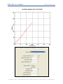
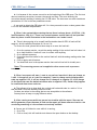
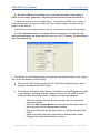
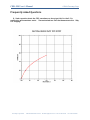
CBR: MS User’s Manual ©2009 Geocomp Corp. Frequently Asked Questions Q. I had a question about the CBR, sometimes we do not get info for the 0.3 in penetration and sometimes we do. I have attached two files that demonstrate this. Why is it stopping? Geocomp Corporation · 1145 Massachusetts Avenue · Boxborough, MA 01719 · Tel 978-635-0012 · Fax 978-635-0266 CBR: MS User’s Manual ©2009 Geocomp Corp. Geocomp Corporation · 1145 Massachusetts Avenue · Boxborough, MA 01719 · Tel 978-635-0012 · Fax 978-635-0266 CBR: MS User’s Manual ©2009 Geocomp Corp. A: It is because of the concave correction at the beginning of the CBR curve. The first test does not need any correction; however the second one does. The curve shifts by the correction amount resulting in missing the 0.3 CBR value. The tests were run with a maximum penetration of 0.3in in the test parameters screen. If you need to obtain the CBR value at 0.3 in. then you need to enter a value greater than 0.3 in for the maximum displacement. Q: When I view system before starting the test there is always about ± 0.005 kN (1 lb) load fluctuations. Why it is? There is no contact between vertical load cell and specimen then why there is small fluctuation in the load and how can I make it zero? A: There is always going to be a small load fluctuation about 0.025% of load cell full capacity, which translates into about 0.1 lb not 1 lb. To re-zero the load, please follow these steps to re-zero the load cell: 1. Go to the system monitor, record the analog reading of the vertical load cell when it is at no load condition. Load cell is not in contact with anything. 2. Go to calibrate summary 3. Overwrite the offset value for the vertical load cell with the analog reading value from step one. 4. Click on apply and ok buttons 5. You should see now in the system monitor that vertical load cell is virtually zero. *Note: This re-zeroing process can be applied to other sensors such as pressure transducer. Q: When I use report soft ware, I want to use scale as I want but it does not change, as I want. It change but not as I want for example If I want to change vertical displacement scale say negative 0.02, it will not change but if I change it to negative 0.2 it will change (in this particular case the default minimum value is negative 0.05). Similar thing happens to normal and shear stress scale too. A: The software tries to keep both the vertical and horizontal scale in a ratio of 1:1 so that the Mohr circles are actually circles not ovals. So there are values in the scaling that are not acceptable to the software. You may have to keep on trying different values. Q: After running a successful test we ran into troubles with the report. We were not able to generate a report because all links on the report pull down menu are inactive. Are we missing something or is the software not entirely installed. A: Once a test is finished or even while it is running, 1. Go to File 2. Click on Load, this will load the test data on the open window on the desktop. Geocomp Corporation · 1145 Massachusetts Avenue · Boxborough, MA 01719 · Tel 978-635-0012 · Fax 978-635-0266 CBR: MS User’s Manual ©2009 Geocomp Corp. 3. Go back to Report, you should see now the Graph, Settings, and Edit menus all activated. 4. You can change units, scales, and edit the test data points. 5. Remember that every time you change or edit something, you will need to save the file, and load it again. Q: During the test, a controller error message appears on the screen telling me that a limit switch is on, what should I do? A: Possible causes are: A limit switch from either the LoadTrac-II has been triggered. Locate the limit switch either the upper or lower one. Lock the piston, manually move the platen, reapply the load before the error message, unlock the piston, and click on Retry button The difference in the strain rate between the specified one and the actual one can be attributed to the following: A.1 The vertical LVDT calibration may be off. Check the calibration factor and if necessary recalibrate the LVDT sensor. A.2 The load step multiplier may need to be adjusted. Assuming that the calibration factor for the LVDT is correct, then follow these simple steps to adjust the load step multiplier Run the LoadTrac-II platen all the way down until it reaches the lower limit switch Go to the View System Monitor and record both the pulse count for the Load motor and the displacement reading Now move the platen all the way up until it reaches the upper limit switch Again record both the pulse count and the displacement reading Compute the load step multiplier as follow: Load Step Multiplier = Δ Vertical travel /Δ Pulse count Adjust the load step multiplier accordingly Q: Could the Node ID# for the LoadTrac-II change by itself? What possible reasons could you think to have prompted the change? A: The defaults node ID# for the LoadTrac-II is 65. If you are using different node ID#’s and reboot the system and by mistake press ESC key on the keypad the E-prom program reverts back to the default values. Just go back to the Setup menu (refer to the LoadTrac-II hardware manual) and change the node ID to whatever value up to 256. Geocomp Corporation · 1145 Massachusetts Avenue · Boxborough, MA 01719 · Tel 978-635-0012 · Fax 978-635-0266 CBR: MS User’s Manual ©2009 Geocomp Corp. Q. We have a CBR test running and an error message that reads:" Load reading of 65528 is out of range” popped up. Why does this show up and how do we prevent it? A: When you receive an error message stating, "Load reading of 65528 is out of range" it means that the load cell sensor has maxed out. Your sample strength is stronger than the capacity of the load cell. You will have to use a higher capacity load cell for this type of soil that you are testing. Q. In Test Parameters screen, the target velocity is entered as 1.27 mm/ min. But during the experiment, the actual velocity is seen as 1.42-1.57 mm/min. We would like to learn the reason of this. A. The difference in the displacement rate between the specified one and the actual one can be attributed to the following: The vertical LVDT calibration may be off. Check the calibration factor and if necessary recalibrate the LVDT sensor. The load step multiplier under Options Hardware Step Multiplier may need to be adjusted. Assuming that the calibration factor for the LVDT is correct, and then follow these simple steps to adjust the load step multiplier: Run the LoadTrac-II platen all the way down until it reaches the lower limit switch Go to the View System Monitor and record both the pulse count for the Load motor and the displacement reading Now move the platen all the way up until it reaches the upper limit switch Again record both the pulse count and the displacement reading Compute the load step multiplier as follows: Geocomp Corporation · 1145 Massachusetts Avenue · Boxborough, MA 01719 · Tel 978-635-0012 · Fax 978-635-0266 CBR: MS User’s Manual ©2009 Geocomp Corp. Load Step Multiplier = Δ Vertical travel /Δ Pulse count Adjust the load step multiplier accordingly Note that the default value is 5.08e-005 mm/pulse count (2.e-006 in./pulse count) The Polarity of the displacement sensor may be wrong. Should be unipolar for Novotecnik sensor (with square cross section). Geocomp Corporation · 1145 Massachusetts Avenue · Boxborough, MA 01719 · Tel 978-635-0012 · Fax 978-635-0266