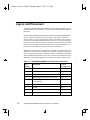
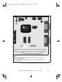
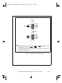
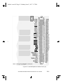
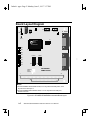
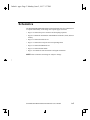
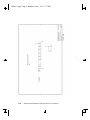
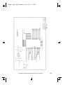
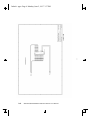
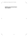
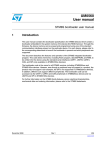
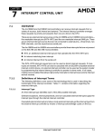
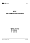
1
frtbook : about1 Page vii Monday, June 2, 1997 3:37 PM About the SD188ES/SD188EM Demonstration Board The AMD® SD188ES/SD188EM Demonstration Board is designed as an exceptionally small, low-cost product for demonstration of the AMD Am188ES and Am188EM microcontrollers. See page ix for a block diagram of the board. 1.1 The SD188ES/SD188EM demonstration board is a stand-alone evaluation platform for the Am188ES or Am188EM microcontroller. The Am188ES and Am188EM microcontrollers integrate peripherals such as 12 chip-select controllers, serial controllers, 32 programmable I/Os, three timers, an interrupt controller, and watchdog timer to increase system functionality while reducing overall cost. The memory controller supports a glueless connection to SRAM, EPROM, Flash memory, and pseudo-static RAM. The Am188ES and Am188EM microcontrollers also feature an innovative bus design that frees the processor to run at nearly twice the speed of standard 80C188 processors while using commodity memory devices. The SD188ES/SD188EM demonstration board is designed with a 104-pin Am188 expansion interface that provides access to the Am188ES and Am188EM microcontrollers signals. The Am188 expansion interface facilitates prototyping with external devices by using the SD188ES/SD188EM demonstration board as the minimal system core of a design. The SD188ES/SD188EM demonstration board highlights the Am188ES and Am188EM microcontrollers’ serial ports, glueless interface to SRAM and Flash memory, and the expansion interface to peripheral attachments. A complete description of the board can be found in Chapter 2, “Demonstration Board Functional Description”. SD188ES/SD188EM Demonstration Board User’s Manual vii frtbook : about1 Page viii Monday, June 2, 1997 3:37 PM Theory of Operation The SD188ES/SD188EM demonstration board demonstrates the basic processor functionality and features of the Am188ES and Am188EM microcontrollers, and the simplicity of their system design. As a stand-alone platform, the board enables you to test the Am188ES and Am188EM microcontrollers’ performance and functionality. The minimal number of components on the board exhibits the integration present in the processor. Demonstration Board Features The SD188ES/SD188EM demonstration board provides the following features: • Am188ES or Am188EM 40-MHz microcontroller • E86™ family boot monitor (E86MON) board-resident utility 1.1 Information on invoking and using the E86MON software is provided in the E86MONTM Software User’s Manual included in your kit. • 128 Kbyte SRAM • 128 Kbyte Am29F010-70 Flash memory • Am188 104-pin expansion interface • Two RS-232 serial ports with DB-9 connectors Please note that the Am188EM microcontroller provides one asynchronous serial port. Thus, when the board is populated with the Am188EM microcontroller, only one serial port is featured. • Activity LED indicators for PIO signals • Power-on LED indicator • Reset circuitry viii SD188ES/SD188EM Demonstration Board User’s Manual frtbook : about1 Page ix Monday, June 2, 1997 3:37 PM Am188ES or Am188EM Microcontroller Address Bus A/D Bus CPU Control Am29F010-70 Flash Bank (128 Kbyte) SRAM Bank (128 Kbyte) Clock & Reset Circuitry Power & Ground 1.1 5.5-mm Barrel Connector Am188 Expansion Interface RS-232 Serial Port Level Converter Circuitry DB-9 Connector RS-232 Serial Port Level Converter Circuitry* DB-9 Connector* *Second asynchronous serial port implemented only with Am188ES microcontroller Figure 0-1. SD188ES/SD188EM Demonstration Board Block Diagram SD188ES/SD188EM Demonstration Board User’s Manual ix frtbook : about1 Page x Monday, June 2, 1997 3:37 PM SD188ES/SD188EM Demonstration Board Documentation The SD188ES/SD188EM Demonstration Board User’s Manual provides information on the design and function of the SD188ES/SD188EM demonstration board. Detailed instructions for using the E86MON software are provided in the E86MONTM Software User’s Manual included in your kit. The demonstration board is shipped with the E86MON software installed in the on-board Flash memory. About This Manual Chapter 2, “Demonstration Board Functional Description” contains descriptions of the basic sections of the demonstration board: layout, processor, Flash memory, SRAM, serial ports, power and signal LED indicators, clock and reset logic, expansion interface, and power-supply circuitry. Chapter 3, “Product Support” provides information on reaching and using the AMD Corporate Applications technical support services, product information available through AMD’s World Wide Web and FTP sites, and support tools for the embedded E86 family. Appendix A, “Layout Diagram, Schematics, and Board Bill of Materials” contains a board layout drawing along with schematics and a Bill of Materials (BOM) for the SD188ES/SD188EM demonstration board. x SD188ES/SD188EM Demonstration Board User’s Manual 1.1 Chapter 1, “Quick Start” provides implementation and installation information for the demonstration board and instructions for invoking the E86MON software. Detailed information on using the E86MON software is provided in the E86MONTM Software User’s Manual included in your kit. frtbook : about1 Page xi Monday, June 2, 1997 3:37 PM Suggested Reference Material For information on ordering the literature listed below, see Chapter 3, “Product Support”. • Am186ES and Am188ES Microcontrollers Data Sheet Advanced Micro Devices, order number 20002 • Am186EM and Am188EM Microcontrollers Data Sheet Advanced Micro Devices, order number 19168 • Am186EM and Am188EM Microcontrollers User’s Manual Advanced Micro Devices, order number 19713 • Am186ES and Am188ES Microcontrollers User’s Manual Advanced Micro Devices, order number 21096 • Am186 and Am188 Family Instruction Set Manual Advanced Micro Devices, order number 21267 1.1 • FusionE86SM Catalog Advanced Micro Devices, order number 19255 • For current application notes and technical bulletins, see our World Wide Web page at http://www.amd.com. SD188ES/SD188EM Demonstration Board User’s Manual xi frtbook : about1 Page xii Monday, June 2, 1997 3:37 PM Documentation Conventions The Advanced Micro Devices SD188ES/SD188EM Demonstration Board User’s Manual uses the conventions shown in Table 0-1 (unless otherwise noted). These same conventions are used in all E86 family support product manuals. Table 0-1. Notational Conventions Usage Boldface Indicates that characters must be entered exactly as shown, except that the alphabetic case is only significant when indicated. Typewriter face Indicates computer text input or output in an example or listing. 1.1 Symbol xii SD188ES/SD188EM Demonstration Board User’s Manual frtbook : ch1 Page 1 Monday, June 2, 1997 3:37 PM Chapter 1 Quick Start This chapter provides information that will help you quickly set up and start using the SD188ES/SD188EM demonstration board. The SD188ES/SD188EM demonstration board is supported by the E86MON software. The E86MON software enables you to load, run, and debug programs on the SD188ES/SD188EM demonstration board. For detailed information on using the E86MON software, refer to the E86MONTM Software User’s Manual included in your kit. For information on how to: • Connect the SD188ES/SD188EM demonstration board to a PC, see page 1-2 1.1 • Invoke the E86MON software, see page 1-4 • Troubleshoot installation problems, see page 1-5 • Locate related sources of information, see page 1-6 SD188ES/SD188EM Demonstration Board User’s Manual 1-1 frtbook : ch1 Page 2 Monday, June 2, 1997 3:37 PM Connecting to a PC Follow the steps below to connect the SD188ES/SD188EM demonstration board to your PC. Installation Requirements The items listed below are necessary to install and run the SD188ES/SD188EM demonstration board: • PC with an available COM port • Terminal emulation software (such as Microsoft Windows® Terminal or ProComm Plus) that supports ASCII file transfers, software flow control (Xon/ Xoff), and send break capability • Power source for universal power supply ! CAUTION: As with all computer equipment, the SD188ES/SD188EM demonstration board may be damaged by electrostatic discharge (ESD). Please take proper ESD precautions when handling any board. 1. Remove the board from the shipping carton. Visually inspect the board to verify that it was not damaged during shipment. 1-2 SD188ES/SD188EM Demonstration Board User’s Manual 1.1 Board Installation frtbook : ch1 Page 3 Monday, June 2, 1997 3:37 PM 2. Connect the demonstration board’s DB-9 serial port (either P1 or P0 on the ES version of the board; P1 on the EM version of the board) to an available COM port. Use the serial cable included in the SD188ES/SD188EM demonstration board kit and note that a DB-9 to DB-25 serial connector adapter is provided if your host system requires it. The pinout of the demonstration board’s serial connector is shown on page 2-9. COM1 COM2 serial cable 1.1 ! DANGER: Make sure the power supply is not plugged into an electrical outlet before connecting it to the SD188ES/ SD188EM demonstration board 3. Connect the power supply to the barrel connector on the SD188ES/SD188EM demonstration board. 4. Apply power to the board by connecting the power supply to an electrical outlet. Once the board is powered up, the LEDs (CR3-CR10) should flash in an oscillating pattern. ! CAUTION: If using your own power supply, ensure that it is a 5-V supply with the proper polarity (see page 2-14). Using a 9-V supply will permanently damage the board. SD188ES/SD188EM Demonstration Board User’s Manual 1-3 frtbook : ch1 Page 4 Monday, June 2, 1997 3:37 PM 5. Invoke the terminal emulation program at 19200 baud, no parity, 8 data bits, and 1 stop bit; enable the software flow control (Xon/Xoff), if supported. 6. Reset the board by depressing and releasing the RESET switch (see location in Figure 2-1 on page 2-3). The LEDs on the board (CR3-CR10) will again flash in an oscillating pattern for three seconds, as they did upon power up. During the three-second period while the LEDs are oscillating, type an a in the terminal window to ensure that the E86MON software uses the correct baud rate. When the E86MON software receives an a, it adjusts its baud rate (if necessary) and displays the welcome message and prompt. If you type a character other than an a, or type no character at all, the E86MON software still displays the welcome message and prompt, but may be using an incorrect baud rate. Depressing and releasing the RESET switch gives you another opportunity to type an a. 7. To display the version of the E86MON software and the commands available, type ? and press Enter. 1.1 For detailed information on using the E86MON software, refer to the E86MONTM Software User’s Manual included in your manual. 1-4 SD188ES/SD188EM Demonstration Board User’s Manual frtbook : ch1 Page 5 Monday, June 2, 1997 3:37 PM Table 1-1. Installation Troubleshooting 1.1 Problem Solution Nothing happens when pushing the RESET button. Sometimes it is difficult to make a good connection when pushing the small RESET button. If all else fails, remove the power supply from the AC electrical outlet and disconnect and reconnect the power supply. The LEDs will flash in an oscillating pattern when the reset is successful. The computer does not respond with the E86MON software prompt. Reset the board by pressing the RESET switch and typing an a while the LEDs are flashing in an oscillating pattern. If this does not work, verify the power, check the cables, etc. After typing a during reset, the terminal emulation software displays unreadable characters. Check the baud rate setting for the terminal emulation software. It should be set to 19200. Also check the word length (8), stop bits (1), parity (N), and turn off any hardware flow control. After a processor reset, the LEDs do not flash in the expected oscillating pattern. Check that the power LED is on and the correct voltage is supplied to the board. Ensure that the polarity of the power connector is correct. The terminal emulation program locks up the software or PC. Check the COM port connection with the target board. Make sure that the same COM port is selected in the terminal emulation software. In some PCs if the correct COM port is not specified, the software will fail to function—it will lock in a continuous loop waiting for an answer from the incorrect serial port. The power LED does not turn on with power. Immediately disconnect the power supply. Ensure that the polarity of the power connector is correct. This is a very serious failure of the hardware. If the power source is connected incorrectly, the board will be permanently damaged. There is a problem you cannot resolve. Contact the AMD Corporate Applications technical support services. (See Chapter 3, "Product Support" for phone numbers and more information.) SD188ES/SD188EM Demonstration Board User’s Manual 1-5 frtbook : ch1 Page 6 Monday, June 2, 1997 3:37 PM For More Information... If you need more information about: • SD188ES/SD188EM demonstration board hardware, see Chapter 2,“Demonstration Board Functional Description” • E86MON software, see the E86MONTM Software User’s Manual • Problems with the board or the E86MON software, see Chapter 3,“Product Support” • SD188ES/SD188EM demonstration board layout and schematics, see Appendix A,“Layout Diagram, Schematics, and Board Bill of Materials” • the Am188ES microcontroller see the Am186ES and Am188ES Microcontrollers Data Sheet 1.1 • the Am188EM microcontroller, see the Am186EM and Am188EM Microcontrollers Data Sheet 1-6 SD188ES/SD188EM Demonstration Board User’s Manual frtbook : newch2 Page 1 Monday, June 2, 1997 3:37 PM Chapter 2 Demonstration Board Functional Description The SD188ES/SD188EM demonstration board provides a completely stand-alone microcontroller-based evaluation platform in a low-cost, exceptionally small formfactor product. The SD188ES/SD188EM demonstration board was designed to meet the needs of customers working with the Am188ES and Am188EM microcontrollers. Read the following sections to learn more about the SD188ES/SD188EM demonstration board hardware: • “Layout and Placement” on page 2-2 1.1 • “Am188ES and Am188EM Microcontroller Implementation” on page 2-4 • “ROM Space” on page 2-7 • “SRAM” on page 2-7 • “RS-232 Serial Ports” on page 2-8 • “Clock and Reset Logic” on page 2-10 • “Am188 Expansion Interface” on page 2-10 • “PIO Activity LED Indicators” on page 2-13 • “Power Supply” on page 2-14 SD188ES/SD188EM Demonstration Board User’s Manual 2-1 frtbook : newch2 Page 2 Monday, June 2, 1997 3:37 PM Layout and Placement The design of the SD188ES/SD188EM demonstration board emphasizes ease of use and small size. Refer to Figure 2-1 on page 2-3 for board layout and component placement. The SD188ES/SD188EM demonstration board has the Flash and SRAM memory devices (U4 and U3) directly below the processor. This placement keeps the memory devices as close as possible to the processor to minimize noise and trace reflections. The 40-MHz fundamental mode crystal (Y1) is located to the right of the processor. The expansion interface (J2 and J3) is located at the bottom of the board for easy connection and access. Finally, the 5.5-mm power-supply barrel connector (J1) is positioned in the upper, left corner of the board. 1.1 The RS-232 serial interfaces are positioned on the right of the board. Please note that the ES version of the board features two serial ports (P0 and P1), which are driven by the two asynchronous serial interfaces on the Am188ES microcontroller. The Am188EM microcontroller provides one asynchronous serial interface so the EM version of the board implements the serial port with a DB-9 connector (P1). Table 2-1. SD188ES/SD188EM Demonstration Board Parts List 2-2 Part Number Description For more information, see CR1–CR10 Power and signal LEDs Page 2-13 J1 Power connector Page 2-14 J2-J3 Expansion interface Page 2-10 U1 Voltage supply supervisor (TI TL7705A) Page 2-10 U2 Am188ES or Am188EM 40-MHz microcontroller Page 2-4 U3 Flash memory Page 2-7 U4 SRAM Page 2-7 U5–U6 RS-232 driver/receiver devices (MAX232) Page 2-8 Y1 40-MHz fundamental mode crystal Page 2-10 SD188ES/SD188EM Demonstration Board User’s Manual frtbook : newch2 Page 3 Monday, June 2, 1997 3:37 PM U6 CR1 U5 P1 ES/EM GND SW1 U1 POWER CR2 Reset Y1 Advanced Advanced Micro Micro Devices Am188EM-40VC CR3 CR4 U2 CR5 CR6 FLASH SRAM CR7 CR8 1.1 CR9 U3 U4 CR10 Advanced Micro Devices SD188ES/EM DEMO BOARD P0 ES Only 32 1 B J2 A C D J3 0 19 Notes: 1.On the SD186ES demonstration board, P1 is asynchronous serial port 0; P0 is asynchronous serial port 1. 2.On the SD186EM demonstration board, P1 is an asynchronous serial port; P0 does not exist. Figure 2-1. SD188ES/SD188EM Demonstration Board Layout SD188ES/SD188EM Demonstration Board User’s Manual 2-3 frtbook : newch2 Page 4 Monday, June 2, 1997 3:37 PM Am188ES and Am188EM Microcontrollers Implementation The SD188ES/SD188EM demonstration board supports the AMD Am188ES and Am188EM microcontrollers. The board is shipped with either an Am188ES or Am188EM microcontroller that operates at 40 MHz. Although not supported by the on-board crystal, the Am188ES and Am188EM microcontrollers are also available in 20-, 25-, and 33-MHz operating frequencies. See Figure 2-2 on page 2-5 for a block diagram detailing the Am188ES microcontroller’s functionality. See Figure 2-3 on page 2-6 for a block diagram detailing the Am188EM microcontroller’s functionality. 2-4 SD188ES/SD188EM Demonstration Board User’s Manual 1.1 The Am188ES and Am188EM microcontrollers are designed to meet the most common requirements of embedded products developed for the communications, office automation, mass storage, and general embedded markets. Specific applications include feature phones, cellular phones, PBXs, multiplexers, modems, disk drive controllers, hand-held and desktop terminals, fax machines, line cards, managed hubs, and industrial control. Refer to the Am186ES and Am188ES Microcontrollers Data Sheet and the Am186EM and Am188EM Microcontrollers Data Sheet for more information on the specific features of the Am188ES and Am188EM microcontrollers. frtbook : newch2 Page 5 Monday, June 2, 1997 3:37 PM PWD INT2/INTA0 INT3/INTA1/IRQ INT1/SELECT INT0 CLKOUTA INT6-INT4 CLKOUTB X2 X1 VCC TMROUT0 NMI Clock and Power Management Unit Interrupt Control Unit Control Registers Control Registers TMRIN0 Pulse Width Demodulator (PWD) DRQ0 DRQ1 DMA Unit Timer Control Unit 0 1 (WDT) 2 0 Max Count B Registers Max Count A Registers 16-Bit Count Registers Control Registers 1 20-Bit Source Pointers 20-Bit Destination Pointers 16-Bit Count Registers Control Registers Control Registers GND TMROUT1 TMRIN1 RES 1.1 Control Refresh Registers Control Unit ARDY SRDY S2-S0 DT/R DEN/DS HOLD HLDA PSRAM Control Unit Chip-Select Unit Asynchronous Serial Port 1 S6/LOCK/ CLKDIV2 PIO31PIO0 Control Registers Asynchronous Serial Port 0 Execution Unit Bus Interface Unit Control Registers PIO TXD0 RXD0 RTS0/RTR0 CTS0/ENRX0 TXD1 RXD1 RTS1/RTR1 CTS1/ENRX1 UZI RD WB A19-A0 LCS/ONCE0 PCS6/A2 PCS5/A1 MCS3/RFSH AO15-AO8 WR MCS2-MCS0 AD7-AD0 RFSH2/ADEN PCS3-PCS0 UCS/ONCE1 ALE Figure 2-2. Am188ES Microcontroller Block Diagram SD188ES/SD188EM Demonstration Board User’s Manual 2-5 frtbook : newch2 Page 6 Monday, June 2, 1997 3:37 PM INT2/INTA0 CLKOUTA INT1/SELECT INT4 INT0 TMROUT0 NMI CLKOUTB TMRIN0 DRQ0 Clock and Power Management Unit Interrupt Control Unit Control Registers Control Registers Max Count B Registers Max Count A Registers 16-Bit Count Registers Control Registers 0 1 20-Bit Source Pointers 20-Bit Destination Pointers 16-Bit Count Registers Control Registers Control Registers GND DRQ1 DMA Unit Timer Control Unit 0 1 (WDT) 2 X2 X1 VCC TMROUT1 TMRIN1 RES Control Refresh Registers Control Unit ARDY SRDY S2-S0 DT/R DEN HOLD HLDA S6/ CLKDIV2 UZI PSRAM Control Unit Execution Unit Bus Interface Unit PIO Asynchronous Serial Port Chip-Select Unit Control Registers Synchronous Serial Interface SCLK WB A19-A0 LCS/ONCE0 AD7-AD0 RFSH2/ADEN SDATA PCS6/A2 SDEN0 SDEN1 PCS5/A1 MCS3/RFSH WR AO15-AO8 MCS2-MCS0 PCS3-PCS0 UCS/ONCE1 ALE Figure 2-3. Am188EM Microcontroller Block Diagram 2-6 PIO0 Control Registers Control Registers RD *PIO31- SD188ES/SD188EM Demonstration Board User’s Manual TXD RXD 1.1 INT3/INTA1/IRQ frtbook : newch2 Page 7 Monday, June 2, 1997 3:37 PM ROM Space The SD188ES/SD188EM demonstration board contains on-board ROM space for use by the E86MON software and application code. This ROM space is implemented as one Am29F010 70-ns Flash memory device. This Flash memory device is mapped to the upper region of addressable memory at E0000h to FFFFFh. The Flash memory device is organized as 128K x 8 bits (eight, 16K sectors) and is connected to the UCS (Upper Memory Chip Select) signal of the microcontroller. After a valid reset, the Am188ES or Am188EM microcontroller fetches the first instruction from the Flash memory device by asserting UCS and driving the address bus with the value FFFF0h. The E86MON software enables you to program the Flash memory device with specific types of hex files. Intel hex and Intel extended hex format files are supported. This software functionality is provided to eliminate the need to remove the Flash memory device. Do not attempt to remove the TSOP Flash or SRAM (U3, U4, U7, and U8) memory devices because doing so may cause damage to the board. 1.1 SRAM The SD188ES/SD188EM demonstration board utilizes SRAM for its read/write storage. The board provides 128 Kbyte of SRAM using one 70-ns device that is mapped from 0h to 1FFFFh. The SRAM device is organized as 128K x 8 bits and is attached to the LCS (Lower Memory Chip Select) signal of the microcontroller. For every access to the above address range, the Am188ES and Am188EM microcontrollers will assert LCS. NOTE: SRAM available to you includes 410h to 1F400h. See the E86MONTM Software User’s Manual included in your kit for more information. SD188ES/SD188EM Demonstration Board User’s Manual 2-7 frtbook : newch2 Page 8 Monday, June 2, 1997 3:37 PM RS-232 Serial Ports The ES version of the SD188ES/SD188EM demonstration board provides two onboard RS-232 serial ports (P0, P1) that are directly driven by the Am188ES microcontroller. The serial ports are equipped with DB-9 DCE connectors. The pin assignment for the DB-9 connectors is shown in Figure 2-4 on page 2-9. The EM version of the SD188ES/SD188EM demonstration board provides one on-board RS-232 serial port that is directly driven by the Am188EM microcontroller. The RS-232 serial port (P1) is equipped with a DB-9 DCE connector. The pin assignment for the DB-9 connector is shown in Figure 2-4 on page 2-9. Traditionally, PCs have Data Terminal Equipment (DTE) ports which connect directly to the Data Communication Equipment (DCE) port on the SD188ES/ SD188EM demonstration board. A null modem cable is not required to connect a DTE port with a DCE port. The RS-232 specification calls for signals that are driven at non-TTL levels. Singlechip RS-232 driver/receiver devices (MAX232, U5 and U6) are used to convert to and from the required voltages. 2-8 SD188ES/SD188EM Demonstration Board User’s Manual 1.1 The Am188EM serial port does not provide RTS and CTS support in hardware. The PSC3 and PSC2 pins are wired to the corresponding signals and can be configured as PIO outputs for limited RTS and CTS support via software. frtbook : newch2 Page 9 Monday, June 2, 1997 3:37 PM P1 NC Note 1 RTS0 CTS0 NC 5 4 3 2 1 9 8 7 6 P0 NC RTS1 CTS1 NC 9 8 7 6 GND NC RXD0 TXD0 NC Note 2 5 4 3 2 1 GND NC RXD1 TXD1 NC 1.1 Notes: 1. The SD188EM serial port does not support RTS0 and CTS0 in hardware. Instead, these signals are connected to PCS3 and PCS2. 2. The SD188EM demonstration board has only one asynchronous serial port. The serial port is connected to P1. Figure 2-4. DB-9 Serial Connector Pinout SD188ES/SD188EM Demonstration Board User’s Manual 2-9 frtbook : newch2 Page 10 Monday, June 2, 1997 3:37 PM Clock and Reset Logic The Am188ES and Am188EM microcontrollers can be configured for either 1x or ½x clock mode. As configured on the SD188ES/SD188EM demonstration board, the microcontroller is in 1x clock mode. The input is generated by a 40MHz fundamental mode crystal (Y1) that is connected to the X1/X2 inputs of the microcontrollers, resulting in a 40-MHz system clock. System reset is controlled by a voltage supply supervisor (TI TL7705A, U1). This device generates the processor’s reset input, asserting the Am188ES or Am188EM microcontroller’s RES pin for 13 ms when the RESET switch is depressed. The voltage supply supervisor also holds reset active when the power falls below 4.75 V. The SD188ES/SD188EM demonstration board supports the PC/104 form-factor expansion-type connector for additional prototyping and testing. The traditional PC/104 signals are not present on the board; however, the Am188 expansion interface enables you to attach wirewrap or prototype boards that have the same standard physical interface. The pinout of the expansion interface for the SD188ES is shown in the figures that follow. NOTE: The pinout of the expansion interface is identical for both the SD188ES and SD188EM demonstration boards except for the four pins shown in Table 2-2. Table 2-2. Expansion Interface SD188ES/SD188EM Pinout Differences 2-10 J2 Pin Number SD188ES Pin Name SD188EM Pin Name B19 RTS0 SCLK B20 TXD0 SDEN0 B21 RXD0 SDEN1 B22 CTS0 SDATA SD188ES/SD188EM Demonstration Board User’s Manual 1.1 Am188 Expansion Interface frtbook : newch2 Page 11 Monday, June 2, 1997 3:37 PM B J2 A 1.1 GND 32 GND 31 NC 30 VCC 29 ALE 28 WLB 27 HLD 26 INT3 25 INT4 24 NMI 23 CTS0* 22 RXD0* 21 TXD0* 20 RTS0* 19 NC 18 MCS0 17 MCS1 16 MCS2 15 MCS3 14 UZI 13 RD 12 WR 11 LCS 10 UCS 9 TMROUT1 8 TMRIN1 7 TMRIN0 6 NC 5 TMROUT0 4 VCC 3 RESET 2 GND 1 32 31 30 29 28 27 26 25 24 23 22 21 20 19 18 17 16 15 14 13 12 11 10 9 8 7 6 5 4 3 2 1 GND MA0 MA1 MA2 MA3 MA4 MA5 MA6 MA7 MA8 MA9 MA10 MA11 MA12 MA13 MA14 MA15 MA16 MA17 MA18 MA19 SRDY ARDY AD0 AD1 AD2 AD3 AD4 AD5 AD6 AD7 NC *Refer to Table 2-2 for a description of these pins. Figure 2-5. Am188 Expansion Interface Pinout (J2) SD188ES/SD188EM Demonstration Board User’s Manual 2-11 C NC 19 AO15 18 AO14 17 AO13 16 AO12 15 AO11 14 AO10 13 AO9 12 AO8 11 NC 10 NC 9 NC 8 PCS0 7 PCS1 6 PCS2 5 PCS3 4 PCS5 3 PCS6 2 BHE 1 GND 0 J3 D 19 18 17 16 15 14 13 12 11 10 9 8 7 6 5 4 3 2 1 0 GND GND DEN VCC DT/R S0 S1 S2 CLKOUTB CLKOUTA DRQ0 DRQ1 NC NC* INT0 INT1 INT2 S6 HOLD GND *This pin is connected to a No Connect pin on the SRAM. Figure 2-6. Am188 Expansion Interface Pinout (J3) 2-12 SD188ES/SD188EM Demonstration Board User’s Manual 1.1 frtbook : newch2 Page 12 Monday, June 2, 1997 3:37 PM frtbook : newch2 Page 13 Monday, June 2, 1997 3:37 PM PIO Activity LED Indicators The SD188ES/SD188EM demonstration board uses on-board LED indicators to show activity on the upper eight programmable I/O (PIO) signals from the Am188ES or Am188EM microcontroller. Table 2-3 shows which PIO signal is represented by each LED. Table 2-3. PIO LED Indicator Interface 1.1 LED PIO Pin Name PIO Register Bit Number CR3 MCS1 15 CR4 MCS0 14 CR5 DEN 5 CR6 DT/R 4 CR7 PCS5 3 CR8 PCS6 2 CR9 TMROUT1 1 CR10 TMRIN1 0 SD188ES/SD188EM Demonstration Board User’s Manual 2-13 frtbook : newch2 Page 14 Monday, June 2, 1997 3:37 PM Power Supply When used as a stand-alone board, the SD188ES/SD188EM demonstration board requires an input power supply of 5.0 V DC, ±5%, 250 mA. When adding components to the SD188ES/SD188EM demonstration board via the expansion interface, additional power may be necessary. The power supply connector is a 5.5-mm barrel connector where the center post is VCC and the outer ring is GND, as shown in Figure 2-7. GND POWER Figure 2-7. Power Supply Polarity ! 2-14 CAUTION: Use the 5-V universal power supply included with the kit. Using a 9-V supply will permanently damage the board. SD188ES/SD188EM Demonstration Board User’s Manual 1.1 +5V frtbook : ch3.fm Page 1 Monday, June 2, 1997 3:37 PM Chapter 3 Product Support This chapter contains information on: • Reaching and using the AMD Corporate Applications technical support services, on page 3-2 • Product information available through AMD’s World Wide Web and FTP sites, on page 3-4 • Support tools for the E86 family, on page 3-5 1.1 SD188ES/SD188EM Demonstration Board User’s Manual 3-1 frtbook : ch3.fm Page 2 Monday, June 2, 1997 3:37 PM AMD Corporate Applications Technical Support Services Technical support for the E86 family of microcontrollers and corresponding support products is available via e-mail, online (BBS and WWW), or through telephone or fax. E-Mail Support Please include your name, company, telephone number, AMD product requiring support, and question or problem in all e-mail correspondence. In the USA and Canada, send mail to: [email protected] In Europe and the UK, send mail to: 1.1 [email protected] Online Support AMD offers technical support on our WWW site, and through our bulletin board services. See “Product Support” on page 3-4 for more on what our WWW and FTP sites have to offer. WWW Technical Support Go to AMD’s home page at http://www.amd.com and click on “Service” for the latest AMD technical support phone numbers, software, and Frequently Asked Questions. Bulletin Board Support 3-2 Country Number USA and Canada (408) 749-4659 UK and Europe 44-(0) 1276-803-211 SD188ES/SD188EM Demonstration Board User’s Manual frtbook : ch3.fm Page 3 Monday, June 2, 1997 3:37 PM Telephone and Fax Support Telephone assistance is available in the U.S. from 8:00 A.M. to 5:00 P.M. Pacific time, Monday through Friday (except major holidays). In Europe, assistance is available during U.K. business hours. Contact the hotlines at one of the following telephone or fax numbers. Direct Dial Numbers Number USA and Canada Tel.: (408) 749-5703 Fax: (408) 749-4753 Japan Tel.: (03) 3346-7550 Fax: (03) 3346-9828 Far East Asia Fax: (852) 2956-0599 Germany Tel.: 089 450 53199 UK and Europe Tel.: 44-(0) 1276-803-299 Fax: 44-(0) 1276-803-298 1.1 Country Toll-Free Numbers Country Number USA and Canada (800) 222-9323 France 0590-8621 Italy 1678-77224 Japan 0031-11-1163 SD188ES/SD188EM Demonstration Board User’s Manual 3-3 frtbook : ch3.fm Page 4 Monday, June 2, 1997 3:37 PM Product Support AMD’s WWW and FTP sites are described below. Questions, requests, and input concerning these sites can be sent via e-mail to [email protected]. WWW Site A subset of the AMD WWW pages, the embedded processor pages are frequently updated and include general product information, technical documentation, and support and tool information. To access these pages, go to the AMD home page at http://www.amd.com and click on “Embedded Processors” or access the pages directly at http://www.amd-embedded.com. The “Embedded Processors” home page is divided into four sections: • “Product Overviews” briefly describes all the microprocessors and microcontrollers in the E86 family, and describes how these parts are ideal in specific focus markets. • “Support and Tools” provides information about the tools that support our processors, and offers online benchmarking tools. • “Technical Documentation” provides the Available Literature List of datasheets, application notes, user’s manuals, and promotional literature, and describes how to order these documents. Many are also available online in PDF form. (To access the Literature Ordering Center via telephone, call one of the numbers listed on the back cover of your manual). • “Demo Board Updates” provides a link to the AMD FTP site where the latest E86MON software releases are availalbe. 3-4 SD188ES/SD188EM Demonstration Board User’s Manual 1.1 • “What’s New” announces new E86 family products, and highlights new applications using our products. frtbook : ch3.fm Page 5 Monday, June 2, 1997 3:37 PM FTP Site In addition to the documentation on our WWW pages, AMD provides software through an anonymous FTP site. To download the software, ftp to ftp.amd.com and log on as “anonymous” using your e-mail address as a password. Or via your web browser, go to ftp://ftp.amd.com. Software relating to the E86 family can be found in the /pub/epd/e86/ directory. Third-Party Development Support Products The FusionE86SM Program of Partnerships for Application Solutions provides the customer with an array of products designed to meet critical time-to-market needs. Products and solutions available from the AMD FusionE86 partners include emulators, hardware and software debuggers, board-level products, and software development tools, among others. The FusionE86SM Catalog, order# 19255, describes these solutions. 1.1 In addition, mature development tools and applications for the x86 platform are widely available in the general marketplace. SD188ES/SD188EM Demonstration Board User’s Manual 3-5 1.1 frtbook : ch3.fm Page 6 Monday, June 2, 1997 3:37 PM 3-6 SD188ES/SD188EM Demonstration Board User’s Manual frtbook : appa Page 1 Monday, June 2, 1997 3:37 PM Appendix A Layout Diagram, Schematics, and Board Bill of Materials This appendix contains a board layout diagram, schematics, and the bill of materials (BOM) for the SD188ES/SD188EM demonstration board. 1.1 SD188ES/SD188EM Demonstration Board User’s Manual A-1 frtbook : appa Page 2 Monday, June 2, 1997 3:37 PM Board Layout Diagram U6 CR1 U5 P1 ES/EM GND SW1 POWER U1 CR2 Reset Y1 Advanced Advanced Micro Micro Devices Devices Am188EM-40VC CR3 CR4 U2 CR5 CR6 FLASH SRAM 1.1 CR7 CR8 CR9 U3 U4 CR10 Advanced Micro Devices SD188ES/EM DEMO BOARD P0 ES Only 32 1 B J2 A C D J3 0 19 Notes: 1.On the SD186ES demonstration board, P1 is asynchronous serial port 0; P0 is asynchronous serial port 1. 2.On the SD186EM demonstration board, P1 is an asynchronous serial port; P0 does not exist. Figure A-1. SD188ES/SD188EM Demonstration Board Layout A-2 SD188ES/SD188EM Demonstration Board User’s Manual frtbook : appa Page 3 Monday, June 2, 1997 3:37 PM Schematics The SD188ES/SD188EM demonstration board schematics have been blocked out to separate functionality of the design onto separate pages as follows: • Page A-4 contains the power connector and decoupling capacitors • Page A-5 contains the Am188ES or Am188EM microcontroller, clock, and reset circuitry • Page A-6 contains the Flash device • Page A-7 contains the serial ports and corresponding LEDs • Page A-8 contains the SRAM device • Page A-9 contains the PIO LEDs • Page A-10 contains the Am188 interface and signal termination NOTE: These schematics and design are subject to change. 1.1 SD188ES/SD188EM Demonstration Board User’s Manual A-3 1.1 © AMD 1996 frtbook : appa Page 4 Monday, June 2, 1997 3:37 PM A-4 SD188ES/SD188EM Demonstration Board User’s Manual © AMD 1996 S6 frtbook : appa Page 5 Monday, June 2, 1997 3:37 PM 1.1 SD188ES/SD188EM Demonstration Board User’s Manual A-5 1.1 © AMD 1996 frtbook : appa Page 6 Monday, June 2, 1997 3:37 PM A-6 SD188ES/SD188EM Demonstration Board User’s Manual © AMD 1996 frtbook : appa Page 7 Monday, June 2, 1997 3:37 PM 1.1 SD188ES/SD188EM Demonstration Board User’s Manual A-7 1.1 © AMD 1996 frtbook : appa Page 8 Monday, June 2, 1997 3:37 PM A-8 SD188ES/SD188EM Demonstration Board User’s Manual © AMD 1996 frtbook : appa Page 9 Monday, June 2, 1997 3:37 PM 1.1 SD188ES/SD188EM Demonstration Board User’s Manual A-9 1.1 Expansion Connector © AMD 1996 S6 frtbook : appa Page 10 Monday, June 2, 1997 3:37 PM A-10 SD188ES/SD188EM Demonstration Board User’s Manual frtbook : appa Page 11 Monday, June 2, 1997 3:37 PM Board Bill of Materials (BOM) Table A-1. SD188ES/SD188EM Demonstration Board BOM 1.1 Qty Ref Description MFG1 Part No 1 1 C1 22 MFd, SMT, C case, 20 V Any 1 C12 1.0 MFd, SMT, 16 V Any 9 C13, C16, C17, C24-C29 0.1 MFd, SMT, 20 V Any 1 C14 15 PFd, SMT, 16 V Any 9 C15, C18-23, C30, C31 22 PFd, SMT, 16 V Any 8 C2-C8, C11 0.01 MFd, SMT, 16 V Any 10 CR1-CR10 LED, 3 Pin, SMT Rohm SLM-23VMW 1 J1 Power Jack, 5.5 mm, RA Switchcraft RAPC-712 0 J2 AM186 Conn, 64-Pin Header Not Populated 0 J3 AM186 Conn 40-Pin Header Not Populated 2 P0*, P1 DB9 right angle connector, Front MetalShell AMP 12 R1, R24-R34 100K Ohms, 5% Any 2 R10, R12 390 Ohms, 5% Any 8 R16-R23 220 Ohms, 5% Any 3 R2, R14, R37 10K Ohms, 5% Any 7 R3-R8, R15 0K Ohms Any 4 R9, R11, R35, R36 33 Ohms, 5% Any 1 SW1 Reset Switch, (SMT-J lead) C&K KT11P3JM 1 U1 Reset Controller, SMT TI TL7705ACD 1 U2 Am188ES Microcontroller or Am188EM Microcontroller AMD 1 U3 128K x 8 Flash EPROM (SMT) AMD Am29F010-70EC 1 U4 128K x 8 SRAM (SMT) Hitachi HM628128T-7 1 U5*, U6 RS-232 Driver, narrow SMT Maxim MAX232ACSE 1 Y1 40.0 MHz High Frequency Quartz Crystal, 16 pF Epson MA-306 787844-1 * Not present on the SD188EM Demonstration Board. SD188ES/SD188EM Demonstration Board User’s Manual A-11 1.1 frtbook : appa Page 12 Monday, June 2, 1997 3:37 PM A-12 SD188ES/SD188EM Demonstration Board User’s Manual frtbook : frtbook.ix Page 1 Monday, June 2, 1997 3:37 PM Index A Am188 expansion interface, See expansion interface Am188EM microcontroller block diagram, 2-6 operating frequency, 2-4 Am188ES microcontroller block diagram, 2-5 operating frequency, 2-4 AM29F010 Flash, 2-7 1.1 B baud rate setting, 1-4 BBS technical support, 3-2 bill of materials, A-11 C clock configuration, 2-10 clock logic, 2-10 clock rates supported, 2-10 COM ports, See ports connecting demo board to PC, 1-2 connectors DB-9, 1-3 conventions documentation, xii CR1–CR10 LEDs location on board, 2-2 CR3–CR10 LEDs on power-up, 1-4 CR3–CR10 PIO LEDs, 2-13 D data bits setting, 1-4 DB–9 serial connector pinout, 2-9 DEN pin, 2-13 documentation conventions, xii description of, x, xi, xii manual contents, x reference material, xi DT/R pin, 2-13 E E86MON utility invoking, 1-4 e-mail technical support, 3-2 expansion interface, 2-10 J2 pinout, 2-11 J3 pinout, 2-12 SD188ES/SD188EM Demonstration Board User’s Manual Index-1 frtbook : frtbook.ix Page 2 Monday, June 2, 1997 3:37 PM F M features SD188ES/SD188EM demonstration board, viii Flash memory overview, 2-7 FTP site, 3-5 FusionE86 program, 3-5 memory Flash, 2-7 ROM, 2-7 SRAM, 2-7 hotline numbers, 3-3 I installation requirements, 1-2 troubleshooting, 1-5 interfaces expansion, 2-10 RS-232 serial, 2-8 J J1, J2, and J3 locations on board, 2-2 L LED LEDs CR3–CR10, 1-4 flashing incorrectly, 1-5 indicators, 2-13 no power, 1-5 PIO indicators, 2-13 Index-2 parity setting, 1-4 PC connecting demo board to, 1-2 PC/104 expansion interface See expansion interface PCS pins, 2-13 pinout AM188 interface (J2), 2-11 AM188 interface (J3), 2-12 DB–9 serial connector, 2-9 RS-232 serial port, 2-8–2-9 PIO signals mapped to LEDs, 2-13 overview, 2-13 ports COM1, 1-3 COM2, 1-3 expansion, 2-10 RS-232 serial, 2-8 serial, 1-3 power supply 5-V vs. 9-V, 1-3 input requirements, 2-14 polarity, 2-14 to the board, 1-3 product support FTP site, 3-5 third party (FusionE86), 3-5 WWW site, 3-4 SD188ES/SD188EM Demonstration Board User’s Manual 1.1 H P frtbook : frtbook.ix Page 3 Monday, June 2, 1997 3:37 PM R RES pin, 2-10 RESET button nothing happens when pushing, 1-5 resetting board with, 1-4 reset logic, 2-10 ROM space, 2-7 RS-232 serial port See ports S 1.1 schematics, A-3 SD188ES/SD188EM demonstration board bill of materials, A-11 block diagram, ix clock logic, 2-10 connecting DB-9 connector to PC, 1-3 design, 2-2 documentation, x expansion interface, 2-10 features, viii installing, 1-3 layout and placement, 2-2 layout illustration, 2-3, A-2 LEDs, 2-13 overview, vii parts list, 2-2 PIOs, 2-13 power supply, 2-14 reset logic, 2-10 ROM space, 2-7 RS-232 serial port, 2-8 schematics, A-3 SRAM, 2-7 technical support, 3-1 serial ports, 1-3 SRAM, 2-7 stop bits setting, 1-4 support, product. See product support. support, technical. See technical support T technical support, 3-1 BBS support, 3-2 e-mail support, 3-2 hotline numbers, 3-3 WWW support, 3-2 terminal emulation program displaying unreadable characters, 1-5 locking up, 1-5 TMRIN1 pin, 2-13 TMROUT1 pin, 2-13 troubleshooting installation, 1-5 U U1–U6 location on board, 2-2 USC (Upper Memory Chip Select) signal, 2-7 W WWW product support, 3-4 technical support, 3-2 Y Y1 location on board, 2-2 SD188ES/SD188EM Demonstration Board User’s Manual Index-3 1.1 frtbook : frtbook.ix Page 4 Monday, June 2, 1997 3:37 PM Index-4 SD188ES/SD188EM Demonstration Board User’s Manual