1
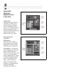
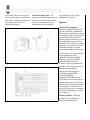
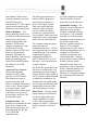
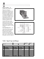
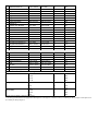
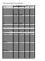
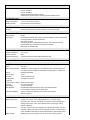
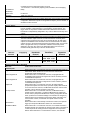
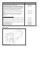
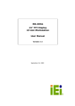
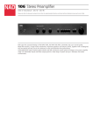
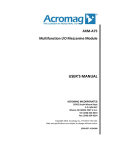
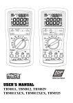
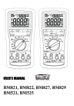
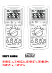
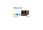
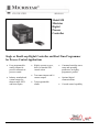
Model 828
Micristar
Digital
Process
Controller
Single or Dual-Loop Digital Controller and Real-Time Programmer
for Process Control Applications
•
Four programmable
analog outputs for
process retransmit or
process control
•
Industry standard and
custom ranges for
thermocouple, RTD
and linear inputs
•
Highly accurate reverse,
direct or bimodal PID
control action
•
•
•
Command cartridge stores
setup and operating
parameters, including
programmer profiles
Ten contact inputs and 16
contact outputs
•
Optional digital
communications
Ten programmable
alarms
•
Cascade control capability
P.O. Box 157, Elk River, MN 55330 USA – (763) 241-1456 – Fax (763) 241-1829
Model 828
Micristar
Digital Process
Controller
Application
The Micristar Digital Process
Controller provides precise
control of process variables
such as temperature, speed,
pressure, etc. With the optional
real-time programmer, the
Micristar can also automate and
repeat control functions
whenever they are needed.
Figure 1. Operator Interface
Description and
Technical
Information
The Micristar is a single or
dual-channel process control
instrument. It consists of the
following major components:
Front Panels – The Micristar
has two front panels. The first
panel, called the operator
interface, allows the user to start
a process recipe and gather
process information (see Figure
1). When this hinged panel is
down, it reveals the second
Figure 2. Primary Interface
panel, called the primary
interface, that accesses the
Micristar’s configuration and
profile programming
capabilities (see Figure 2).
Automatic transfer between the
operator interface and primary
interface is accomplished
through electronic sensing.
Three hidden security keys
allow access to the primary
interface which helps prevent
accidental changes to
configuration and real-time
programmer information.
The primary interface is in
limited access when the
operator interface is first pulled
down. In limited access, all
primary interface values can be
displayed but the only values
that can be changed are those
which were changeable using
the operator interface. Full
access allows all controller and
programmer table parameters to
be changed.
The Micristar’s front panel is
divided into four logical areas
with bold touch pads and LED
displays:
• With a scrolling
technique, the process
status window allows
users to display setpoint,
process input variable,
setpoint deviation,
percent output and
alarms in engineering
units.
• Centered in the manual
control area, manual
operator functions
include manual process
control, program recipe
start (for
controller/programmer
models) and print
commands.
•
•
The process and controller
status window on the
operator interface becomes
the controller or
programmer tuning and set
up area on the primary
interface. The LED display
in this area allows display
of controller parameters
and programmer
parameters where
applicable. In full access,
process control or
programmer parameters are
manipulated via the manual
control area.
The command cartridge
part will accept either the
optional command
cartridge or optional range
cartridge.
Analog Input Types – One input
is provided for each channel.
Industry standard input types are
supported:
• Thermocouple type T, J, K,
R, S, E, Platinell II, B, G,
C, D and Nickel Nickel
Molly.
• RTD (100 ohm, American
or European curves)
• Linear DC ranges of 0–
100mv, 0-50mv, 0-10mv, 5-10mv, 0-10 volt, 0-5
volt, 0-1volt, 4-20mA, 020mA and 1-5mA
In addition, special input types can
be developed for to meet other
requirements.
Control Output Types – The
Micristar’s four analog and two
time proportioned outputs control
a wide variety of power controls,
CAT valves, PAT valves, heaters,
burners and
other final control devices
which accept a DC voltage,
current signal or on/off contact
input. The analog outputs can
be configured as 0-5VDC, 020mA or 4-20mA and can also
be used to retransmit set point,
process actual or deviation
signals from the Micristar to a
chart recorder or other device.
Contact Inputs – Twelve
contact inputs are provided for
a variety of functions (see
Specifications).
Control Actions – The type of
control action can be defined
as reverse, direct or bimodal as
required to control
temperature, relative humidity
or virtually any other process
condition.
Control Strategies – The
Micristar can be used
effectively with advanced
control strategies including:
• Cascade control
• Guaranteed soak
• Remote Setpoint
generation
• Ratio control
• Auto/Manual control
with bumpless transfer
• External program hold,
start, abort, output
suppression and panel
security switches
Alarms – Each channel has a
High and Low process variable
limit and process deviation
alarm to enable corrective
action to be taken when a
process deviates from
its Setpoint. There are also sensor
failure alarms and a special Watch
Dog Timer Alarm that continuously
verifies that the Micristar is
functioning properly.
Electrical Connections – All
signal and control input and output
electrical connections are made at
the screw terminals on the rear
terminal board or the optional
relay board at the rear of the
Micristar (see Figure 3).
Options
Real-Time Programmer –
Micristar models 828D and 828E
provide a real-time programmer.
The real-time programmer contains
a 50-segment (step) recipe that can
ramp or soak both channels of
process control, switch any or all of
the eight digital outputs, and act
upon any or all of the eleven digital
inputs. Recipes can be stored on a
command cartridge or central
supervisory computer for later use.
Figure 3. Back Panel
A time of day start feature enables
the programmer to begin
automatically during off-peak
hours or prior to the workday.
Controlled abort and stop
sequences can be programmed to
provide a safe exit from a process
that must be terminated.
Recipes are easily entered or
selected using the PGMR
TABLES, SCROLL,
INCREASE/DECREASE and
ENTER keys on the front panel. A
programmed recipe log worksheet
can be used to document controller
and programmer information for
any recipe to provide a permanent
record of each segment in a recipe
(see Figure 4).
Remote Setpoint – Micristar
models 828C and 828E have a
remote Setpoint input for
Figure 4. A Typical Process Recipe
each channel. When remote
Setpoint operation is used, the
controller Setpoint is
determined by 0-5 VDC signals
connected to terminals on the
Micristar’s rear terminal board.
Relative Humidity – The
relative humidity option uses a
dry bulb/wet bulb measurement
method to provide precise
control of temperature and
humidity. The Micristar
compares temperatures of the
dry bulb and wet bulb
(thermocouples or RTDs) and,
based on a psychometric
principles, calculates the
relative humidity. This provides
display programming and
control in percent RH without
the added cost of an RH
transmitter.
Advanced Valve Control –
The position adjusting
transmitter (PAT) option
provides two PAT stations.
Each station can control a
motorized actuator with
slidewire feedback that opens or
closes a valve. When assigned
to a control signal, a PAT
station allows the control signal
to position a valve from 0.0
percent (fully closed) to 100.0
percent (fully open).
The data logger option uses a
built-in software program to
provide process reports to a
printer. The logger’s output
shows the current date/time,
controller values (Setpoint,
process variable, deviation,
percent out), controller mode
(auto, manual), alarm status and
programmer values (programmer
status, run time and recipe ID).
two time proportioned outputs.
The relay board is ordered
separately from the Micristar.
Command Cartridge – The
Micristar can store and retrieve
information in an optional
solidstate command cartridge
(see Figure 5). The command
cartridge is a memory module
that plugs into the cartridge port
on the lower right of the
Micristar’s primary panel (see
The computer communications
Figure 6). The command
option provides two
communications ports – one for
cartridge has two sides, each of
data logger and one for computer which can independently store a
complete set of Micristar
communications. The computer
controller, programmer and
communications port is
configuration data. Complete
configurable as RS422 or
process profiles can be loaded in
RS232. With RS-422, up to 31
seconds, ensuring totally
Micristar’s can be networked to
repeatable results from every
a single computer.
programmer recipe. Data stored
The IEEE-488 option allows the on the command cartridge can
Micristar to communicate with
also be transferred between
instrumentation on the General
Micristar’s. Command cartridges
Purpose Interface Bus (GPIB). It are ordered separately from the
can be ordered with the Micristar Micristar.
or added after installation. No
internal software modifications
are necessary; the Micristar will
automatically locate the IEEE488 board when powered up.
Relay Board – The relay board
option mounts on the Micristar
rear panel and provides relay
output capabilities for alarm,
event or time-proportioning
Communications – The
Micristar can communicate with outputs (see Figure 3). The board Figure 5. Command Cartridge and
has the capacity for 10 relays
supervisory computers and
Range Cartridge
and
other instruments at up to 19.2
K baud through RS-422, RS232 or IEEE-488
communications.
Range Cartridge – The
optional range cartridge (see
Figure 5) is a factoryprogrammed module that also
plugs into the cartridge port on
the Micristar’s primary panel.
The range cartridge can be used
to reprogram the Micristar to
use a variety of different sensors
and ranges (see Table 1). It is
ordered separately from the
Micristar. An input module
(ordered separately) is also
Figure 6. The Micristar with a Plugged-in Command Cartridge
required if the input module
number for the new range does
not match the input module
number for the existing range.
Input module numbers are listed
in Table 1.
Rack Mounting Panel – A 19
inch (483 mm) rack mounting
panel with cutouts for three
Micristars can be ordered
separately from the Micristar.
If one or two of the cutouts will
not be used to mount Micristars,
filler plates can also be ordered.
Figure 7. Typical Rear View
Table 1. Input Types and Ranges
Setpoint Range
Input Type
Degrees C
Degrees F
-20.6 to 759.7
-5.1 to 1400.0
Input Module
Number
Selection
Code
03
101
Thermocouple
J
K
Iron vs.
Copper-Nickel
-20.6 to 386.6
-5.1 to 728.1
02
102
Iron-Constantan
-124.7 to 186.0
-192.4 to 366.8
06
103
Nickel-Chromium vs.
-26.6 to 1371.5
-16 to 2500
04
201
Nickel-Aluminm
-26.6 to 510.8
-15.8 to 951.7
02
202
Chrome-Alumel
-182.8 to 246.3
-297.1 to 475.3
06
203
-
Platinel II
-35.0 to 1379.6
-31 to 2516
04
211
-14.5 to 521.2
5.9 to 970.2
02
212
-
Nickel vs. Nickel
0.0 to 1350.8
32 to 2462
19
251
18% Molybdenum
E
T
S
Nickel-Chromium vs.
0 to 1932
05
301*
-17.8 to 721.9
0.0 to 1331.5
04
302
Copper-Nickel
-17.8 to 300.9
0.0 to 573.8
02
303
Chromel-Constantan
-267.9 to 300.1
-449.9 to 571.9
07
304
Copper vs.
-419.7 to 402.7
722.9 to 756.5
07
401*
Copper-Nickel
-27.4 to 403.9
-17.3 to 758.7
02
402
Copper-Contantan
-200.1 to 213.4
-328.2 to 416.2
06
403
-73 to 1822
-100 to 3312
02
501
-74 to 1768
-101 to 3215
02
511
Platinum vs.
Platinum-10% Rhodium
R
-17.8 to 1054.9
Platinum vs.
Platinum-13% Rhodium
B
Platinum-6% Rhodium vs.
Platinum-30%Rhodium
39 to 1846
102 to 3354
01
521**
G
Tungsten vs.
-429 to 2361
-741 to 4282
03
601*
C
D
Tungsten-26% Rhenium
-131.1 to 1317.8
-204 to 2406
02
602
Tungsten-5% Rhenium vs.
-81 to 2392
-113 to 4337
03
611*
Tungsten-26% Rhenium
-30.5 to 1159.4
-23 to 2118
02
612
Tungsten-3% Rhenium
-119 to 2406
-183 to 4364
03
621*
-41.9 to 1146.3
-43 to 2095
02
622
RTD
-200.0 to 649.9
-328 to 1202.6
11
701
100 ohm
-100 to 250.0
-148.0 to 481.8
10
702
Platinum
0.0 to 200.0
32.0 to 392.0
09
703
American Alpha (1)
0.00 to 99.98
32.0 to 212.0
08
704
RTD
-203.7 to 660.2
-334.4 to 1219.1
11
711
100 ohm
-101.2 to 253.5
-150.2 to 488.2
10
712
Platinum
0.0 to 202.8
32.0 to 397.0
09
713
European Alpha (2)
0.00 to 101.31
32.0 to 214.5
08
714
(G3) Tungsten-25% Rhenium
RTD
-
-
Linear
Input Range
Millivolt
0 to 100
0 to 50
0 to 10
05
04
01
801
802
803*
-5 to 10
06
804
0 to 10
0 to 5
14
13
811
812
0 to 1
12
813
4 to 20
0 to 20
15
16
901
902
Voltage
Current (MA)
1 to 5
17
903
* Input resolution slightly reduced in these ranges
** Accuracy specification does not apply below 250 degrees F (125 degrees C) American Curve (1)=.003920 per ohm per degree C European Curve
(2)=.00385 per ohm per degree C
Table 2. Special Input Types and Ranges
Input Type
Thermocouple
T
S
G3
G3
R
J
R T/C
C T/C
K T/C
NI vs. NI-18% Mo
N T/C
B T/C
K T/C
R T/C
N T/C
E T/C
K T/C
S T/C
RTD
100 ohms European
100 ohms European
100 ohms European
Linear
RTC 11c Pyrometer
(1.19mV - 19.08mV)
RTC 11c Pyrometer
(1.19mV - 19.08mV)
Pyrometer
(0.013mV - 28.771mV)
Pyrometer
(0V - 10V)
Altitude Sensor
(4mA - 20mA)
Type RTC Retransm.
(0V - 9.5357V)
Pyrometer Retransm.
(0V - 7.2862V)
Type RTC Retransm.
(0V - 9.5541V)
Type STC Retransm.
(0V - 11.0345V)
Altitude Sensor
(4mA - 20mA)
Pyrometer
(-0.0265mV - 1.504V)
Land oRo Pyro
Setpoint Range
Degrees C
Degrees F
Input Module
Number
Selection
Code
-27.4 to 287.1
-133.4 to 1378.1
-31.1 to 1304.7
0.0 to 1638.4
0.0 to 1001.0
-17.8 to 538.3
0.0 to 1350.8
0.0 to 1638.4
-128.8 to 1371.1
0.0 to 1350.8
-40.0 to 1421.6
37.9 to 1638.7
-17.8 to 788.0
-17.8 to 892.1
0.3 to 1286.9
-195 to 649
-212 to 1038
0.0 to 15.00
-17.3 to 548.8
-208 to 2514
-24 to 2380
32 to 2980
32 to 1834
0.0 to 1001.0
32 to 2462
32 to 2980
-200 to 2500
32 to 2462
-40 to 2591
100 to 2981
0.0 to 1448.8
0 to 1638.4
33 to 2348
-320 to 1200
-350 to 1900
32 to 2732
1
1
2
106
107
106
1
106
4
105
4
1
106
107
4
111
112
1
451
551
651
654
552
151
553
659
253
251
631
554
254
555
665
351
255
556
5.00 to 55.02
-40.00 to 70.09
-5.03 to 50.02
41.0 to 131.0
-40.0 to 158.0
22.94 to 122.03
103
104
103
751
752
753
700.00 to 1420.0 1292 to 2588
2
653
771.2 to 1583.3 1420.2 to 2881.7
2
655
600.0 to 1305.5 1112.0 to 2381.1
106
656
685 to 1850
1265 to 3362
14
657
0.0 to 120.0
0.0 to 120.0
15
951
750.0 to 1520.3 1382 to 2768
14
854
800.0 to 1620.0 1472 to 2948
14
855
850.0 to 1720.2 1562 to 3128
14
856
900.0 to 1850.0 1652 to 3362
14
857
0.0 to 80.0
0.0 to 80.0
15
952
685 to 1425
1265 to 2597
109
658
1
660
1000.0 to 1400.0 1832.0 to 2552.0
(3.54mV - 16.08mV)
Land oQo Pyro
(6.547 - 50.73mV)
PR 401 Pyro
(.19 - 23.80mV)
RP-LD32 Pyro
(.022 - 72.85mV)
RH Pyrometer
(.13 - 56.54mV)
RT/C RETR
(0V - 9.0211V)
Current SP 0-20mA
RGE Accur 4-20mA
Current SP 0-20mA
RGE Accur 4-20mA
Current SP 0-20mA
RGE Accur 4-20mA
Current SP 0-20mA
RGE Accur 4-20mA
Linear
Voltage
Voltage
Current
Current
Voltage
1100.0 to 1400.0 2012.0 to 2552.0
4
661
600.0 to 1800.1 1112 to 3272
2
662
699.9 to 1609.7 1292.0 to 2930.7
19
663
500.0 to 1870.0 932 to 3398
4
664
650.0 to 1150.0 1202.0 to 408.0
14
858
600.0 to 1300.0 1112.0 to 2372.0
1000.0 to 1300.0 1832.0 to 2372.0
600.0 to 1225.0 1112.0 to 2237.0
975.0 to 1225.0 1787.0 to 2237.0
600.0 to 1300.0 1112.0 to 2372.0
980.0 to 1300.0 1796.0 to 2372.0
600.0 to 1500.0 1112.0 to 2732.0
1000.0 to 1500.0 1832.0 to 2372.0
Input Range
0V to 1.4V
0mV to 200mV
0mA to 21.6128mA
0mA to 164.08mA
-10V to 10V
16
956
16
957
16
958
16
959
18
102
16
108
110
852
853
953
954
955
Specifications
Dimensions
Bezel Max. Dimensions
Cut-Out Dimensions
Length
5.87 Inches (149 MM) wide x 5.89 Inches (150 mm) high x 0.87 Inches (22 mm)
Deep.
5.43 Inches (139 mm) x 5.43 Inches (139 mm)
(1/2 DIN = 138mm square – Reference DIN43700)
12.06 Inches (307mm) Maximum from Bezel Mounting Surface to Farthest Rear
Projection with No Attached Options.
13.25 Inches (338mm) Maximum with the Optional Relay Board Attached
15.25 Inches (388 mm) Maximum with Both Optional Relay Board and
Optional
IEEE-488 Board Attached.
Weight
Without Options: 6.75 Pounds (3.0 kilograms)
With Optional Relay Board: 7.1 pounds (3.2 kilograms)
With Both Optional Relay Board and Optional IEEE-488 Board: 7.2 Pounds
(3.3 Kilograms)
Voltage
120 or 240 VAC (+10 percent, -15 percent)
Frequency
47 to 63Hz
Current
0.5 Ampere at 120VAC, or 0.25 Ampere at 240 VAC (exclusive of relay drives)
Power
60 Watts (typical) or 75 Watts (with relay board)
Isolation
The circuitry is organized into four elements, each with 1000 VDC Isolation:
Process Variable 1
Process Variable 2
Digital Logic/Communications Interface
Contact Inputs, Contact outputs, Analog Outputs and Relay Drives
Environmental Limits
Operating Temperature
Storage Temperature
Relative Humidity
32 °F to 122°F (0°C to 50°C)
-13°F to 140°F (-25°C to 60°C)
0 to 90 Percent, Non-Condensing
Operating Modes
Auto/Manual
Run/Hold
Simultaneously Selected for Both Channels in Two-Channel Units
Simultaneously Selected for Both Channels in Two-Channel Units
Process Control Types
Manual Control
Auto Control
000.0 to 100.0 Percent Reverse Output and/or 000.0 to 100.0 Percent Direct
Output
Output PID Parameters (Four groups; channel one/direct, channel one/reverse,
Channel two/direct, channel two/reverse)
Gain: 000.0 to 200.0
Auto Reset: 00.00 to 75.00 Repeats Per Minute with Anti-Reset Windup
Manual Reset: 00.0 to 99.9 Percent, Reverse and Direct
Rate: 00.00 to 99.99 Minutes
Real-Time Programmer Capacities
Number of Segments
50
Number of Setpoints
One or Two
Number of Events
Eight
Segment Sequencing
Forward or Backward Jumps with Nested Recycling
Real-Time Programmer Update Time
0.2 Second
Analog Inputs
Temperature
Linear
Open Sensor Protection
Filtering
Minimum Span
Resolution
Sampling Rate
Conformity
(Thermocouple or RTD)
Accuracy
Repeatability
Noise Rejection
Temperature Stability
Control Outputs
Output Action
Output Signal Types
Time-Proportioned
Output Limiting
Industry Standard Thermocouples (1 Meg-ohm input resistance) and RTDs
mA, mV, V
Available for Thermocouple, RTD, and Millivolt Inputs. Controller Response
to an Open Sensor Condition is Selectable as “Output Hold” or “Output Off”.
Keyboard Selectable
10 mV
12 Bits (0.025 percent)
5 Samples Per Second
±0.03 Percent of Span
±0.1 Percent of Span
.03 Percent of Span
Normal Mode: Determined by the Value of the Filter Selected
Common Mode: Greater than 120 dB at 60 Hz
Ambient Temperature Affects Input by 0.02 Percent of Input
Span Per Degree C
User Configurable as Reverse, Direct, or Bimodal
Analog: Four outputs, each configurable as direct- or reverse-acting
and as 0-5 VDC, 0-20 mA, or 4-20 mA. The minimum load for voltage-type
analog outputs is 300 ohms. The maximum load for current-type analog
outputs is 600ohms.
Two open-collector relay drive signals at up to 80 mA each (using ±24 VDC
excitation output). Each output can be configured as direct- or reverse-acting
and is available on both the rear terminal board and the optional relay board.
Separately Set for Each Output (reverse- and/or direct-acting) of Each
Bimodal Band
Relationship
Update Time
Resolution
Controller Channel as High Limit and/or Low Limit
-10.0 Percent to +10.0 Percent (adjoining band, deadband, and overlapping
Band)
0.2 Second
10 Bit (0.10 percent)
Retransmit Outputs
Zero to four analog outputs are available depending on the process control output
configuration. Retransmit outputs are assignable as setpoint, process variable, or
deviation for either channel.
Process Alarms
There can be up to five alarms per channel: 1) High Process Variable; 2) Low
Process Variable; 3) High Deviation; 4) Low Deviation; 5) Open Sensor. The
trigger levels for the process variable and deviation alarms are User-entered.
Each alarm is independently assignable to any of the 16 Alarm/event relay drive
outputs.
Alarm and/or Event outputs
There are 6 relay drive outputs, each of which can supply up to 80mA using The
±24 VDC excitation output. However, the total current drain of all relay Drive
outputs that are energized at one time cannot exceed 500 mA. Six relay Drive
outputs are available at screw terminals on the rear terminal board. Ten Relay
outputs connect to the optional relay board through a ribbon cable. Any Process
alarm or programmer event (or combination of alarms and events) Can be
assigned to any relay drive output. The Watch Dog Alarm has one Form C
mechanical relay (NO and NC) on the rear terminal board.
Serial Communication Standard
Hardware
Topography
Standard
RS-232
Point to Point
Handshake
Protocol
INQ/ACK Or None
RS-422
Multidrop Bus
ENQ/ACK
Baud Rate
300, 1200,2400
4800, 9600, 19.2K
300, 1200, 2400
4800, 9600, 19.2K
Separation
Distance
50’ (15.24 m)
4000’ (1219.2m)
Parallel Communication Standards
IEEE-488
GPIB Parallel Interface Bus
Contact Inputs
Program Hold
Start at Segment 50
Start at Segment 49
Outputs Off
Security Lockout
Print Demand
Auto/Manual Mode
When terminal Cl-1 is connected to common, the programmer enters the
HOLD mode. When terminal Cl-1 is removed from common, the
programmer enters the RUN mode.
When terminal Cl-2 is connected to common, the programmer will
immediately begin execution of segment 50. This is commonly used for
controlled abort sequences.
When terminal Cl-3 is connected to common, the programmer will
immediately begin Execution of segment 49. This is commonly used for
controlled abort sequences.
When terminal Cl-4 is connected to common, all analog and time
proportioned outputs are turned off (to 0 percent output). When terminal
Cl-4 is removed from common, The Micristar will resume normal control
operation. This is used for emergency shut-down.
When terminal Cl-5 is connected to common, the Micristar enters a
special security mode which: 1) Keeps the Micristar from entering full
access mode; 2) Keeps the Micristar from entering configuration access
mode; 3) Allows the command cartridge to be read but not changed; 4)
Allows recipes to be reviewed but not changed. When Terminal Cl-5 is
removed from common, the Micristar front panel resumes normal
operation.
When terminal Cl-6 is momentarily connected to common, the optional
logger port will print the Micristar’s status on an external Printer.
When terminal Cl-7 is connected to common, the controller executes a
bumpless transfer from automatic to manual control mode. This leaves all
control outputs at the existing levels and suppresses PV and process
alarms. When terminal Cl-7 is removed from common, the controller
executes a bumpless transfer from manual to automatic control mode, the
alarms are reactivated and PID control resumes.
When terminal Cl-8 is connected to common, the Micristar accesses the
remote setpoint option. When terminal Cl-8 is removed from common, the
Micristar controls to its internally programmed Setpoint.
Remote Setpoint
When terminal Cl-9 is connected to common, the Micristar will resume
operation where it stopped when power was cut (auto restart). When
terminal Cl-9 is removed from common, the Micristar will return its
memory to default values after power is cut (cold start).
When terminal Cl-10 is connected to common, a host computer can read
data from the Micristar via the computer communication option but it
cannot change the data. When terminal Cl-10 is removed from common, a
hast computer can both read and change data in the Micristar.
Auto Restart
Computer Lockout
Ordering Information
Model
828 Micristar Digital Process Controller
Code Base Model
B
C
D
E
Controller
Controller with remote setpoint
Controller/Programmer
Controller/Programmer with remote setpoint
Code Control Version
10
11
12
Standard Control
Relative Humidity (requires two-channel unit)
PAT Outputs (requires Base Model C or E; for relays, order relay board and two relays-solid state
only-per output)
Code Channel 1 Input Range
See Select Range Code from Table 1*
Table
1 For Special Ranges** see Table 2
Code Channel 2 Input Range
000 None (defines as single channel unit)
See Select Range Code from Table 1* (defines as two-channel unit). For Special
Table Ranges** see Table 2
1
Code Relay Board
0
1
No
Yes
Code Digital Communications
0
1
2
3
4
5
828 D
11
101
101
1
2
None
Logger
Serial Communications RS422/RS232 and Logger
IEEE 488 Communications
IEEE 488 Communications and Logger
IEEE 488 Communications, RS422/RS232 and Logger
0
00
<---------MODEL NO.
(example)
* For two loop units, if one input range is for a thermocouple, the thermocouple range must be assigned to Channel 1.
** For Special Ranges, consult factory for pricing.
Description
Accessories
Command Cartridge (memory storage device)
Standard Range Cartridge - allows any standard linearization table
to be loaded for either Channel 1 or Channel 2 if range change is
desired. If existing Input Module matches new range, linearization
cartridge may be used to change range without changing Input
Modules. See Table 1.(contains ranges listed in Table 1).
Model Number
065332-001
067512-001
067512-002
Special Range Cartridge. See Table 2. (contains ranges listed in
Table 2)
Standard Input Module (XX in model number is input module
number from Table 1. If changing range, also order Range
Cartridge.)
065424-0XX
Plug-in Relays for Relay board:
Solid State Relay (AC only, 120 or 240 VAC, 3A @ 25 °C, 2A @ 50
°C )
067018-001
Solid State Relay (DC only, 4 to 60 VDC, 2-1/2A @ 25 °C, 2A @ 50
°C )
073829-001
Mechanical Relay (SPDT, 3A resistive, up to 120 VAC / 28 VDC)
Paper for Logging Printer ( 1 roll )
Micristar User Manual ( B&C )
Micristar User Manual ( D&E )
065331-001
074018-001
063252-001
063241-001
Dimensions
ALL DIMENSIONS IN INCHES