1
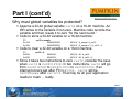
www.pumpkininc.com Maximizing Runtime Performance in Peripheral-Rich MSP430 Applications Andrew E. Kalman, Ph.D. Slide 1 Introduction • Andrew E. Kalman www.pumpkininc.com President and CTO, Pumpkin, Inc. Author of Creator of the 20+ years of embedded systems design and programming experience Contact: [email protected] Slide 2 Outline www.pumpkininc.com • Overview: Seminar Goals • Part I: Interrupts Explained • Part II: Interrupts on the MSP430 • Part III: A Basic Example: Interrupt-driven MSP430 UART Routines • Part IV: A Complex Example: Bit-banged Tx/Rx UART using MSP430’s Timer A • Part V: Impact of RTOS on Interrupts • Part VI: Additional Interrupt Topics • Part VII: Summary Slide 3 Interrupts Explained www.pumpkininc.com • Interrupts provide a means of changing the Program Counter (PC) – and hence which code is executed by the CPU – based on internal or external events. • Interrupt code is executed from Interrupt Service Routines (ISRs). ISRs are vectored. • Interrupts have often priorities associated with them. • Interrupts can be nested. • Servicing an interrupt can be thought of as a context switch. • ISRs can normally call code anywhere in program memory. • Instruction sets and architectures often have specific features to improve interrupt-handling performance. Slide 4 Part I (cont’d) www.pumpkininc.com • When an interrupt occurs: Interrupts are typically disabled (prevents unwanted nesting). The PC and certain registers (e.g. STATUS) are saved on the stack. The PC changes to the starting address of the ISR. The ISR is executed to completion. The saved registers are restored from the stack, interrupt are reenabled, and program execution resumes where it left off in noninterrupt code. • A non-standard return-from-interrupt may be required when e.g.: The processor is in a low-power mode. Exception handling is required. An RTOS is used to schedule tasks. Slide 5 Part I (cont’d) www.pumpkininc.com • Interrupts preempt normal code execution. Interrupt code runs in the foreground. Normal (e.g. main()) code runs in the background. • Interrupts can be enabled and disabled. Globally. Individually on a per-peripheral basis. Non-Maskable Interrupt (NMI). • The occurrence of each interrupt is unpredictable.* When an interrupt occurs. Where an interrupt occurs. • Interrupts are associated with a variety of on-chip and offchip peripherals. Timers, SCI, A/D & D/A. NMI, change-on-pin. Slide 6 Part I (cont’d) www.pumpkininc.com • Well-written ISRs: Should be short and fast. Should affect the rest of the system as little as possible. Require a balance between doing very little – thereby leaving the background code with lots of processing – and doing a lot and leaving the background code with nothing to do. • Applications that use interrupts should: Disable interrupts as little as possible. Respond to interrupts as quickly as possible. • CPU Architectures can help by: Assisting interrupt handling via dedicated instructions. Vectoring interrupt sources. Providing configurable interrupt priorities. Individual control of interrupt enables. Slide 7 Part I (cont’d) www.pumpkininc.com Why must global variables be protected? Assume a 32-bit global variable var32 on a 16-bit machine. An ISR writes to the variable if non-zero. Mainline code records the variable and then resets it to zero “for the next round.” Code to store a 32-bit variable on a 16-bit machine: PC 0x131E 0x1324 var32 = sample; 924200020402 924202020602 MOV.W &_sample, &_var32 MOV.W &_sample + 2, &_var32 + 2 Code to clear a 32-bit variable on a 16-bit machine: PC 0x5332 0x5336 var32 = 0; 82430402 82430602 MOV.W #0, &_var32 MOV.W #0, &_var32 + 2 Since it takes two instructions to zero var32, consider the case when var32 is 0x0801F3CE. In two instructions, var32 will go from 0x0801F3CE to 0x08010000 to 0x00000000. If an interrupt occurs just after PC=0x5332, var32 will be 0x0000xxxx after var32=0. That may be all your application needs to crash … badly. Slide 8 Interrupts on the MSP430 www.pumpkininc.com • MSP430 has 16 Interrupt vectors. Some vectors have sub-vectors (e.g. Timer_A1’s TAIV). Similar parts may have different vector tables! • Interrupts have fixed priority. • Once in the ISR, interrupts are disabled.They can be automatically re-enabled on exit via RETI. MSP430 compilers automatically add RETI to the end of declared ISR code. • A single stack is used for all register saves, etc. Therefore limited in depth only by available RAM. • Global Interrupt bit GIE in the Status Register SR/R2 • Individual peripherals usually have: Module Enable Bit Module Interrupt Enable Bit (IE) Module Interrupt Flag (IF) Slide 9 Part II (cont’d) MSP430F169 Interrupt Vector Table www.pumpkininc.com Slide 10 Part II (cont’d) www.pumpkininc.com Interrupt acceptance on the MSP430: 1) Any currently executing instruction is completed. 2) The PC, which points to the next instruction, is pushed onto the stack. 3) The SR is pushed onto the stack. 4) The interrupt with the highest priority is selected if multiple interrupts occurred during the last instruction and are pending for service. 5) The interrupt request flag resets automatically on single-source flags. Multiple source flags remain set for servicing by software. 6) The SR is cleared. This terminates any low-power mode. Because the GIE bit is cleared, further interrupts are disabled. 7) The content of the interrupt vector is loaded into the PC: the program continues with the interrupt service routine at that address. Slide 11 Interrupt-driven MSP430 UART Routines www.pumpkininc.com Slide 12 Part III (cont’d) www.pumpkininc.com • Simplified overview of UART’s Tx interrupt system: Interrupts are enabled via a single bit (UTXIEn in IEn). An interrupt is generated when the outgoing character has left the Transmit Buffer for the Transmit Shift Register, thus freeing the Transmit Buffer for another character. Single-buffered. • For efficient use of the UART, we’ll fill a buffer with characters and have the Tx ISR automatically send the characters out until the buffer is empty.The buffer will be filled from background code (e.g. somewhere in a main loop), and it will be emptied via foreground code (the Tx ISR). Slide 13 Part III (cont’d) www.pumpkininc.com Initialization (UART0 Tx & Rx): unsigned int tx0Count, tx0InP, tx0OutP,rx0Count, rx0InP, rx0OutP; char tx0Buff[TXO_BUFF_SIZE], rx0Buff[RX0_BUFF_SIZE]; void OpenUSART0 ( unsigned int UCTL_UTCTL, unsigned int URCTL_UMCTL, unsigned int BR1_BR0) { P3OUT &= ~BIT5; P3DIR &= ~BIT5;P3SEL |= BIT5; P3OUT |= BIT4; P3DIR |= BIT4; P3SEL |= BIT4; // pin inits // “” rx0Count = 0; rx0InP = 0; rx0OutP = 0; tx0Count = 0; tx0InP = 0; tx0OutP = 0; // buffer inits // “” UCTL0 = ((UCTL_UTCTL & 0xFF00)>>8) + SWRST; UTCTL0 = ((UCTL_UTCTL & 0x00FF)>>0) ; URCTL0 = ((URCTL_UMCTL & 0xFF00)>>8) ; UMCTL0 = ((URCTL_UMCTL & 0x00FF)>>0) ; UBR10 = ((BR1_BR0 & 0xFF00)>>8) ; UBR00 = ((BR1_BR0 & 0x00FF)>>0) ; // module init as per TI’s instructions // “” // “” // “” // “” // “” ME1 // enable Tx and Rx modules |= UTXE0 + URXE0; UCTL0 &= ~SWRST; // finish init IE1 |= URXIE0; // enable Rx ints } Slide 14 Part III (cont’d) www.pumpkininc.com Enqueueing a single outgoing byte into a Tx buffer: unsigned char putcharTx0(unsigned char data) { if (tx0Count < TX0_BUFF_SIZE) { tx0Buff[tx0InP++] = data; // if there's any room in the buffer ... // put it in there ... if (tx0InP > TX0_BUFF_SIZE-1) { tx0InP = 0; } // wrap the input ptr if necessary ... _DINT(); tx0Count++; IE1 |= UTXIE0; _EINT(); // general case -- see note on slide 21 // update count (a shared global variable) ... // force an interrupt now that data is ready to be sent return TRUE; } else { return FALSE; } } Slide 15 Part III (cont’d) www.pumpkininc.com Dequeueing a single outgoing byte from the Tx buffer: void ISRTx0 (void) __interrupt[UART0TX_VECTOR] { sendcharTx0(); } void sendcharTx0(void) { TXBUF0 = tx0Buff[tx0OutP++]; // send char out UART transmitter if (tx0OutP > TX0_BUFF_SIZE-1) { tx0OutP = 0; } // wrap output ptr if necessary tx0Count--; // update count if (tx0Count == 0) { IE1 &= ~UTXIE0; } // if that was the last one, disable further interrupts } Slide 16 Part III (cont’d) www.pumpkininc.com This code satisfies our requirements for the ISR and overlying code because: The code is relatively small. Interrupts are disabled for a very short time (3 instructions): _DINT(); 32C2 IE2 |= UTXIE1; F2D020000100 tx1Count++; 92534A04 _EINT(); 32D2 DINT BIS.B #0x20, &1 ADD.W #1, &_tx1Count EINT The system overhead is quite good – characters can be enqueued into the buffer as fast as possible with no delays, and then they are removed from the buffer at the baud rate. Time spent within the ISR is quite short – mainly buffer management. Only shared global variable needing protection is count. Slide 17 Part III (cont’d) www.pumpkininc.com Enqueueing a single incoming byte into the Rx buffer: void ISRRx0 (void) __interrupt[UART0RX_VECTOR] { rcvcharRx0(); } void rcvcharRx0(void) { if (rx0Count < RX0_BUFF_SIZE) { rx0Buff[rx0InP++] = RXBUF0; if (rx0InP > RX0_BUFF_SIZE-1) { rx0InP = 0; } // watch for overruns when updating count // take char from UART receiver and place in buffer // wrap input ptr if necessary rx0Count++; } } Slide 18 Part III (cont’d) www.pumpkininc.com Dequeueing a single incoming byte from an Rx buffer: unsigned char getcharRx0( unsigned char * dataP ) { if (rx0Count) { *dataP = rx0Buff[rx0OutP++]; // if there's any char in the buffer ... // get it ... if (rx0OutP > RX0_BUFF_SIZE-1) { rx0OutP = 0; } // wrap the output ptr if necessary ... _DINT(); rx0Count--; _EINT(); // general case -- see note on slide 21 // // update count (a shared global variable) ... return TRUE; } else { return FALSE; } } Slide 19 Part III (cont’d) www.pumpkininc.com • With two UARTs each with dedicated Tx and Rx ISRs and mainline code, maximum interrupt latency is only 2 + 3 + 2 + 3 = 10 instructions. This is good for the UARTs and the system as a whole. • Can be optimized by observing that increments and decrements of (16-bit) int-sized count variables on the MSP430 are atomic and do not require disabling of interrupts. This drops the latency down to only 2 + 2 = 4 instructions (in putcharTxn()). Slide 20 Part III (cont’d) www.pumpkininc.com • Further optimization is possible on the MSP430. In the transmitter, it’s unnecessary to disable global interrupts when (re-)enabling transmit interrupts (it’s atomic). Therefore we’ve removed all interrupt latency: unsigned char putcharTx0(unsigned char data) { if (tx0Count < TX0_BUFF_SIZE) { tx0Buff[tx0InP++] = data; unsigned char getcharRx0( unsigned char * dataP ) { if (rx0Count) { *dataP = rx0Buff[rx0OutP++]; if ( tx0InP > TX0_BUFF_SIZE-1) { tx0InP = 0; } if (rx0OutP > RX0_BUFF_SIZE-1) { rx0OutP = 0; } tx0Count++; IE1 |= UTXIE0; rx0Count--; return TRUE; return TRUE; } } else { return FALSE; } } else { return FALSE; } } Slide 21 Part III (cont’d) www.pumpkininc.com • When compared to this interrupt-based UART approach, a non-interrupt-based approach has the following characteristics: On the Tx side, a new character cannot be sent until the TXEPT flag is set. At very high speeds (e.g. 115,200bps), this may be more efficient (I.e. smaller code size and quicker outputs). But at low speeds (e.g. 9,600bps), looping to poll this bit prevents any other background code from executing. On the Rx side, the faster the baud rate, the more often the receiver must be polled to avoid overrun errors. Even a low baud rate requires tat the application poll within a critical period or errors will return. • Not using interrupts requires the use of polling. Polling is inefficient, because it consumes CPU cycles that could otherwise be spent on other things. Slide 22 Bit-banged Tx/Rx UART using MSP430’s Timer A www.pumpkininc.com • Existing MSP430 application using: USART0: Tx/Rx @ 9600, SPI and I2C. USART1: Tx/Rx @ 9600. DMA, ADC, P1, P2, etc. • Needed a 4800bps receiver and 1200bps transmitter. Incoming and outgoing packets vary in length. • Solution: Dedicate Timer_A0 to 4800bps receiver, and Timer_A1 to 1200bps transmitter. Move OSTimer() (@100Hz) from Timer_A0 to Timer_A2. • Note: Timer_A0 is on one interrupt vector, and Timer_A1 & Timer_A2 are on another. Slide 23 Part IV (cont’d) www.pumpkininc.com ISR for 1200bps bit-banged transmitter: void Timer_A1 (void) __interrupt[TIMERA1_VECTOR] { switch (TAIV) { case 2: CCR1 += SWUART_TX_BITTIME; SWUART_Tx_XmtBit(); break; case 4: CCR2 += TIMERA2_RELOAD; OSTimer(); break; case 10: default: while(1); break; // every 833us // every 10ms // probably should check for overflow ... // error check -- should NOT get here } } • SWUART_Tx_XmtBit() is a state machine to output a nullterminated string by bit-banging an output port. It sets a single bit flag when done. Slide 24 Part IV (cont’d) www.pumpkininc.com • Instead of disabling interrupts globally when dealing with the 1200bps transmitter or the RTOS, individual control is used: void CSK_SWUART_Tx_XmtStr(void) { TxByteCount = 0; TxBitCount = 0; CCR1 = TAR + SWUART_TX_BITTIME; CCTL1 |= CCIE; } void OSDisableHook(void) { CCTL2 &= ~CCIE; } // setup for Tx of string // “” // start 1 bit time from now // and go! // b/c Timer A2 interrupt calls OSTimer() • No need to disable interrupts globally when Timer_A1 is easily controlled via CCIE bit. • 1200bps timing accuracy is more important than absolute accuracy of 10ms system tick timer OSTimer(). Therefore SWUART_Tx_XmtBit() was located in the highest possible remaining timer slot available, and OSTimer() below it. Slide 25 Part IV (cont’d) www.pumpkininc.com • How to pass information up to the overlying application without requiring the disabling of interrupts? One solution is to employ a single bit as a binary semaphore, which is tested-and-cleared in the background with protection, and if originally found to be set, signal another background process: if (statusBits->SWUARTStrSent == 1) { CCTL1 &= ~CCIE; statusBits->SWUARTStrSent = 0; CCTL1 |= CCIE; OSSignalBinSem(BINSEM_XMITDONE_P); } • In this example, Timer_A1 interrupts are disabled for only 3 instructions. Slide 26 Part IV (cont’d) www.pumpkininc.com • The receiver posed a greater challenge: Higher bit rate requires higher interrupt priority to ensure timely processing. Higher processing rate also requires HFXTAL as MCLK. • Approach was similar to transmitter – a FSM was employed to sample incoming bits once start bit falling edge was detected via capture mode hardware. • Some interleaving of ISR processing was used to avoid excessively long execution in any particular state of the FSM. • Need to pass information from ISR (complete received char) to background process just like transmitter. Slide 27 Part IV (cont’d) www.pumpkininc.com • Review: Transmitter: Interrupt-driven. At adequate priority. Related interrupt control does not affect any other interrupts. Highly responsive system because driving background process launches immediately upon end-of-transmission (no polling). Receiver: Interrupt-driven. At higher priority due to higher bit rate. Related interrupt control does not affect any other interrupts. Highly responsive system because driving background process launches immediately upon end-of-transmission (no polling). Slide 28 Impact of RTOS on Interrupts www.pumpkininc.com • An RTOS performs context switches based on predefined behavior (e.g. time slicing, event-driven task scheduling, etc.). Normal operation involves register saves and restores, manipulation of the stack, and changes to global variables. For all of these reasons, an RTOS must typically disable interrupts during a critical section. • Disabling interrupts in a critical section prevents corruption of the RTOS’ global variables (e.g. task control blocks) when RTOS services that act on these variables are called from within ISRs. Slide 29 Part V (cont’d) www.pumpkininc.com • How the RTOS controls interrupts during critical sections may be critical to the performance of your application. If interrupts are disabled globally in critical sections, you’ll need to characterize how long they are disabled. Too long a period and your peripheral performance may be limited. If interrupts are disabled on a per-peripheral basis in critical sections, the RTOS’ impact on interrupts is limited to the particular peripherals. In some RTOSes it is possible to avoid the need to disable interrupts in a critical section by using a simple semaphore-based approach to pass information from the ISR level up to the background level and into the RTOS. Slide 30 Additional Interrupt Topics www.pumpkininc.com • Interrupt-related runtime problems can be exceptionally hard to debug. Common interrupt-related errors include: Failing to protect global variables (sometimes due to feature creep). Forgetting to actually include the ISR in the application. No linker error! Not testing or validating thoroughly. The window in which some interrupt-related errors can occur can be as small as a single instruction. Stack overflow. Overlooking errata or peculiarities (e.g. MSP430’s DMA). Running out of CPU horsepower to execute the ISR fast enough. Thinking that you can detect a “bad time for interrupts” from inside the ISR by checking a flag set in the background and thereby avoid corrupting a background process. Trying to outsmart the compiler. Slide 31 Summary www.pumpkininc.com • By coding efficiently you can run multiple peripherals at high speeds on the MSP430. • Polling is to be avoided – use interrupts to deal with each peripheral only when attention is required. • Allocate processes to peripherals based on existing (fixed) interrupt priorities. Certain peripherals (e.g. DMA) can tolerate substantial latency. • Use GIE when it’s shown to be most efficient and the application can tolerate it. Otherwise control individual IE bits to minimize system interrupt latency. • An interrupt-based approach eases the handling of asynchronous events. Slide 32 www.pumpkininc.com Live Demo Q&A Session Thank you for attending this Pumpkin seminar at the ATC 2006! Slide 33 Notice www.pumpkininc.com This presentation is available online in Microsoft PowerPoint and Adobe Acrobat formats at: ® ® ® ® www.pumpkininc.com/content/doc/press/Pumpkin_MSP430ATC2006.ppt and: www.pumpkininc.com/content/doc/press/Pumpkin_MSP430ATC206.pdf Slide 34 Suggested Reading www.pumpkininc.com 1. MSP430x15x, MSP430x16x, MSP430x161x Mixed Signal Microcontroller, Texas Instruments Datasheet SLAS368D, October 2002. 2. MSP430x1xx Family User’s Guide Revision F, Texas Instruments SLAU049F, 2006. 3. Salvo User Manual, Pumpkin, Inc., 2003. Slide 35 Appendix www.pumpkininc.com • Speaker information Dr. Kalman is Pumpkin's president and chief technology architect. He entered the embedded programming world in the mid-1980's. After co-founding Euphonix, Inc – the pioneering Silicon Valley high-tech pro-audio company – he founded Pumpkin to explore the feasibility of applying high-level programming paradigms to severely memory-constrained embedded architectures. He holds two United States patents and is a consulting professor at Stanford University. • Acknowledgements Pumpkin’s Salvo and CubeSat Kit customers, whose real-world experience with our products helps us improve and innovate. • Salvo, CubeSat Kit and CubeSat information More information on Pumpkin’s Salvo RTOS and Pumpkin’s CubeSat Kit can be found at http://www.pumpkininc.com/ and http://www.cubesatkit.com/, respectively. • Copyright notice © 2006 Pumpkin, Inc. All rights reserved. Pumpkin and the Pumpkin logo, Salvo and the Salvo logo, The RTOS that runs in tiny places, CubeSat Kit, CubeSat Kit Bus and the CubeSat Kit logo are all trademarks of Pumpkin, Inc. All other trademarks and logos are the property of their respective owners. No endorsements of or by third parties listed are implied. All specifications subject to change without notice. First presented at the TI MSP430 Advanced Technical Conference in Dallas, Texas on November 7-9, 2006. Slide 36