1
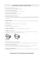
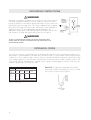
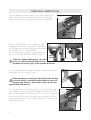
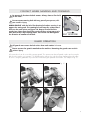
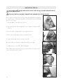
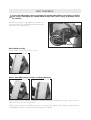
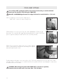
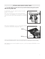
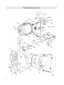
Jancy RadiusMaster OPERATOR’S MANUAL WARNING! before use, be sure everyone using this machine reads and understands all safety and operating instructions in this manual. EYE PROTECTION REQUIRED DUSK MASK RECOMENDED NEVER PLACE FINGERS INSIDE BELT AREA LINE VOLTAGE PRESENT KEEP AWAY FROM FLAMMABLE MATERIALS Model #RAM1000 Serial # Date of Purchase Jancy RadiusMaster Congratulations on your purchase of a Jancy RadiusMaster. Please take a moment to complete and mail your product warranty registration card. Doing so will validate your machine’s warranty period and ensure prompt service if needed. Thank you for selecting a product from Jancy Engineering Inc.. table of contents Important Safety Instructions . . . . . . . . . . . . . . . . . . . . . . . . . . . . . . . . . . . 3-4 Special Instructions . . . . . . . . . . . . . . . . . . . . . . . . . . . . . . . . . . . . . . . . . 5 Grounding Instructions and Extension Cords . . . . . . . . . . . . . . . . . . . . . . . . . 6 Contents of Package . . . . . . . . . . . . . . . . . . . . . . . . . . . . . . . . . . . . . . . . 7 Getting Started . . . . . . . . . . . . . . . . . . . . . . . . . . . . . . . . . . . . . . . . . . . . 7 Machine Operation . . . . . . . . . . . . . . . . . . . . . . . . . . . . . . . . . . . . . . . . . 8 Guard Operation . . . . . . . . . . . . . . . . . . . . . . . . . . . . . . . . . . . . . . . . . . 9 Belt Replacement . . . . . . . . . . . . . . . . . . . . . . . . . . . . . . . . . . . . . . . . . 10 Belt Tracking . . . . . . . . . . . . . . . . . . . . . . . . . . . . . . . . . . . . . . . . . . . . 11 Tool Rest Fitting . . . . . . . . . . . . . . . . . . . . . . . . . . . . . . . . . . . . . . . . . 12-13 Motor Breakdown and Parts List . . . . . . . . . . . . . . . . . . . . . . . . . . . . . . 14-15 limited warranty Jancy Engineering Inc. will, within Eighteen (18) months year from the original date of purchase, repair or replace any goods found to be defective in materials or workmanship, provided the product warranty registration card has been returned to Jancy Engineering Inc. within thirty (30) days of purchase date. This warranty is void if the item has been damaged by accident, neglect, improper service or other causes not arising out of defects in materials or workmanship. This warranty does not apply to machines and/or components which have been altered, changed, or modified in any way, or subjected to use beyond recommended capacities and specifications. Electrical components are subject to respective manufacturers’ warranties. All goods returned defective shall be returned prepaid freight to Jancy, which shall be the buyer’s sole and exclusive remedy for defective goods. In no event shall Jancy Engineering be liable for loss or damage resulting directly or indirectly from the use of merchandise or from any other cause. Jancy Engineering is not liable for any costs incurred on such goods or consequential damages. No officer, employee or agent of Jancy is authorized to make oral representations of fitness or to waive any of the foregoing terms of sale and none shall be binding on Jancy. Jancy Engineering reserves the right to make improvements and modifications to design without prior notice. 2 important safety instructions WARNING! when using electric tools, basic safety precautions should always be followed to reduce risk of fire, electric shock and personal injury. READ AND SAVE ALL INSTRUCTIONS FOR FUTURE REFERENCE. 1.Keep Work Area Clean • Cluttered areas and benches invite injuries. 2.Consider Work Area Environment • Do not expose power tools to rain. • Do not use power tools in damp or wet locations. • Keep work area well lit. • Do not use tool in presence of flammable liquids or gases. 3.Guard Against Electric Shock • Prevent body contact with grounded surfaces. For example: pipes, radiators, ranges and refrigerator enclosures. Disconnect from power source when not in use. Never use if electrical cord is damaged or wet. Always keep electrical cord clear of rotating parts and belt while in motion. 4.Keep Children Away • Do not let visitors contact tool or extension cord. • All visitors should be kept away from work area. 5.Dress Properly • Do not wear loose clothing or jewelry. They can be caught in moving parts. • Non-skid footwear is recommended when working outdoors. • Wear protective hair covering to contain long hair. 6. Use Safety Glasses • Also use face or dust mask if cutting operation is dusty. Everyday eyeglasses only have impact resistance lenses, they are NOT safety glasses. 7.Wear a Dust Mask • Some dust created by grinding activities contains chemicals known to cause cancer, birth defects or other reproductive harm. Provide adequate ventilation. 8.Keep All Guards in Place • Keep all guards in place and in working order. 9. Avoid Contact With The Belt • The abrasive belt when running is an aggressive cutting tool. Extra care should be exercised when using coarse grit belts due to their rapid cutting action. 10.Secure The Jancy RadiusMaster • Bolt the Jancy RadiusMaster securely to the stand ensuring that the stand is bolted to a stable surface to stop it from tipping over or moving when in use. 11.Before Servicing • Disconnect the tool before servicing the unit. 3 important safety instructions 12.Reduce The Risk of Unintentional Starting • Make sure switch is in the off position before plugging in. 13.Never Leave Tool Running Unattended • Turn power off. Don’t leave tool until it comes to a complete stop. 14.Do Not Use Near Flammable Materials • Sparks from the grinding opperation can cause fire. 15.Sharpen Cutting Tools In Proper Direction • Always sharpen cutting tools especially knives, scissors, chisels, etc. with the cutting edge facing downwards and in the direction of rotation of the belt. NEVER face the cutting edge upward against the rotation of the belt; this can result in injury. 16.Hold Matterial Tightly • Always hold the work piece firmly when grinding and apply light and steady pressure against the abrasive belt. 17.Don’t Force Tool • It will do the job better and safer at the rate for which it was designed. 18.Don’t Over Reach • Keep proper footing and balance at all times. 19.Do Not Use Damaged Belts • Belts that show signs of wear or are torn should be replaced before continuing use. 20.Install Belts in Correct Direction • Install belts with the arrows on the back of the belt facing the correct direction. Belts with a lap joint must be mounted facing the correct direction. See diagram below (Fig1. 1). Fig. 1.1 21.Never Use The Back Of The Large Drive Wheel • Using the back of the large drive wheel will cause debris to travel upwards and contact operator or bystanders. 22.Keep RadiusMaster Properly Maintained • Ensure contact wheels and drive wheels are in good condition and are free from cuts or splits that can be a danger in operation. Replace all damaged contact wheels before operating machine. 23.Only Use Recommended Accessories • Consult the owner’s manual for the recommended accessories. The use of improper accessories may cause risk of injury to persons. IMPORTANT: KEEP THESE INSTRUCTIONS FOR FUTURE REFERENCE 4 special instructions WARNING! do not operate machine if warning and /or instruction labels are missing or damaged. contact jancy engineering for replacement labels. 5 grounding instructions WARNING! Improperly connecting the grounding wire can result in the risk of electrical shock. Check with a qualified electrician if you are in doubt as to whether the outlet is properly grounded. Do not modify the plug provided with tool. Never remove the grounding prong from the plug. If the cord or plug is damaged, have it repaired before using. If the plug will not fit the outlet, have a proper outlet installed by a qualified electrician. The Jancy RadiusMaster must be plugged into an appropriate outlet, properly installed and grounded in accordance with all codes and ordinances. The plug and outlet should look like those in Figure A. WARNING! do not use slugger drilling machines on surfaces or materials being welded. doing so can result in personal injury and /or damage to the slugger drilling machine. extension cords Use only 3-wire extension cords that have 3-prong grounding-type plugs and 3-pole receptacles that accept the tool’s plug. Replace or repair damaged cords. Make sure your extension cord is in good condition. When using an extension cord, be sure to use one heavy enough to carry the current your product will draw. An undersized cord will cause a drop in line voltage resulting in loss of power and overheating. Jancy recommends using a minimum 12 gauge extension cord not to exceed 100 feet. The table below is supplied only as a guide to minimum gauge for extension cords, where the smaller the gauge number, the heavier the cord. minimum gauge for extension cords volts total length of cord in feet 120V 240V 0-25 0-50 26-50 51-100 51-100 101-150 101-200 201-300 18 18 16 14 16 16 16 12 16 14 14 Drip Loop: To help prevent cutting fluids from traveling along power cord and contacting power source, tie a drip loop in power cord as shown in Figure B. amperage 0-6 6-10 10-12 12-16 14 12 12 not recommended recommended wire gauge *jancy recommends using a minimum cord not to exceed 100 feet. 12 gauge extension Fig. B 6 operating instructions (before you begin ) Remove all contents from packaging and inspect to ensure no damage was incurred during shipping. Your RadiusMaster package should also include the following: description part # qty operator’s manual LIT116 1 Allen Wrench 5 mm 0070588 1 Allen Wrench 6 mm 058112 1 Swivel Table Complete RAM1011 1 Tool Rest RAM1182 1 Motor Swivel Mounting Plate RAM1012 1 PLATTEN TABLE FOR SQ. EDGE RAM1148T 1 48" x 2"Belt (Customer choice) 5 getting started CAUTION! always disconnect Jancy RadiusMaster from power source before making adjustments. WARNING: Ensure the Jancy RadiusMaster switch is in the off position before plugging in the power lead to the power outlet. Ensure the power cable is not in a position where it can come into contact with any moving parts of the Jancy RadiusMaster. STEP 1) Remove the Jancy RadiusMaster from the carton and unscrew the timber packing base. STEP 2) Attach to the pedestal with the appropriate size bolts, nuts and washer (provided). A solid, stable mounting is required for this tool. See figure 2.1 Bolt the pedestal to a stable surface. Fig. 2.1 STEP 3) Become familiar with the operation and selection of various position of the tool prior to plugging the tool to power and switching on. Ensure the power is turned OFF and the belt has come to a complete stop before attempting to rotate or tilt the Jancy Radius Master. Failure to do so could result in injury to the operator and other persons. The Jancy Radius Master is fitted with a Lock out key fitted to the master switch. It is r ecommended that the key be removed when the machine is not in us to prevent un trained unauthorized us of the machine. or To activate the power lift the switch. To stop the machine, push the switch downwards. 7 operating instrucions The Jancy Radius Master can be rotated to access various work areas. Lift knob “A” and rotate to the desired position. With knob “A” released the machine can be indexed to the next designated position. See figure 2.2 Fig. 2.2 Knob “A” After loosening the locking lever “D”, see Fig 2.3,the Jancy RadiusMaster can be tilted on its side at 90° so that accurate profile grinding, pipe notching etc can be performed. When in position tighten lever ”D”. The WORK TABLE provided can be set to give angles or notch from 90° to 45°. See section TOOL REST AND TABLE FITTING for instruction. Locking Lever “D” Failure to retighten Locking Lever “D” could result in the tool becoming unstable during operation and causing injury to the operator and others. Fig. 2.3 The Jancy Radius Master has three different diameter contact wheels that can be changed with out tools for a variety of work. Before attempting to rotate the small contact wheel carriage ensure the power is turned OFF and the Belt has come to a complete stop. Failure to do so could result in injury to the operator and other persons. To select the desired size contact wheel, pull Knob “E” (see figure 2.4) out and while holding it out rotate the contact wheel carriage releasing the Knob “E” so that it locks the carriage into the desired position. There is no need to release belt tension or use any tool to rotate this carriage. Ensure the carriage is oriented correctly and the pin locked in position (see figure 2.5) before re commencing work and turning the tool ON. 8 Fig. 2.3 Knob “E” contact wheel sanding and polishing Be aware of direction the belt rotates. Always have a firm hold of the work . Fig. 2.6 Do not contact moving belt with any part of your person, this can result in injury. AVOID CONTACT with the belt. The abrasive belt when running is an aggressive cutting tool. The rotating belt will transfer a downward force on the work piece see figure 2.6. Keep a firm hold of the work piece. Extra care should be exercised when using coarse grit belts due to their rapid cutting action. Feed work into belt against the direction of rotation of the belt. guard operation All guards must cover the belt unless that work station is in use. Never remove the guards attached to the machine. Removing the guards can result in serious injury. All contact wheels can be covered by swinging guards. The operator must have all guards in place and covering the belt when the machine is in operation. The guards may be swung to the side when using that particular work station. Be sure to swing the guard back in position when finished using the particular work station. See example in fig 3.1. Fig. 3.1 9 hanging belts Turn machine OFF, unplug machine and remove lock out key to avoid accidental starting of the machine while Ensure the belt has completely stopped before attempting to change the belt. Fig. 3.2 Turn the machine off and ensure the belt has completely stopped before attempting to change the belt. To eliminate the possibility of accidental and its potential danger remove the lock out key. 1. Open all guards on the machine as in fig 3.2. 2. Push or pull any part of the belt applying force to engage the locking catch as in fig 3.3. 3. Ensure the catch is engaged before removing the belt fig 3.4. Fig. 3.3 4. Remove the belt and replace with the desired belt fig 3.5. 5. Replace the belt and release the catch as in fig 3.6. 6. Ensure the belt is over the three contact wheels before proceeding. Fig. 3.4 7. Track the belt as in next section “BELT TRACKING” Note: Locking catch will operate in any position the machine is inclined. You may need to lift or push the lever to unlock. Locking Catch Fig. 3.5 Fig. 3.6 10 belt tracking Ensure the belt always covers completely the contact wheel being used. Failure to do this can result in damage to the contact wheel and possible serious injury to operator and or by standers. Belt tracking is the side to side adjustment of the belt over the contact wheels. This can be achieved by activating the Tracking Lever as detailed in fig 3.7. Fig. 3.7 Tracking Lever Belt tracked correctly. Contact wheel covered when machine is in use. Fig. 3.2 Below: Belts NOT tracked correctly, needing adjustment. Fig. 3.2 Fig. 3.2 With the machine running adjust the tracking by moving the Tracking lever detailed in fig 3.7 up or down to position where the belt will cover the contact wheels. NOTE: As the construction of each abrasive belt varies you may need to adjust the Belt Tracking for each belt used on the RadiusMaster 48. Also as belts wear Belt Tracking may be required. 11 tool rest fitting Turn machine OFF, unplug the machine and remove lock out key to avoid accidental starting of the machine while fitting the TOOL REST. Maintain a MAXIMUM gap between the edge of the tool rest and the belt or 1/16 inch. STEP 1) To attach the tool rest loosen the clamps Fig 4.1 RAM1148T - Locates in the same mounting holes. Fig. 4.1 STEP 2) Slide the tool rest into position Fig 4.2. With a MAXIMUM of 3/16 inch gap between the Tool rest and the belt, apply light downward pressure to seat the Tool Rest into position. Tighten the clamp lever and ensure the tool rest is firmly mounted. Fig. 4.2 STEP 3) Once in position the angles of the tool rest can be adjusted Fig 4.3 as desired by loosening Screws and setting to the required angle and retightening the screws. Fig. 4.3 Adjust angle of Tool Rest with screws Grinding sharp internal square corners can be done on the Tool Rest by tracking the belt over the edge of the contact wheel by 1/32” to 1/16”. Be sure to re track the belt when this operation finished to avoid damage to contact wheels as detailed earlier in this document. CAUTION! When fitting the platen table RAM1148T in the tool rest position, clearance from the belt must be no more than 1/32" (0.8mm). 12 fitting and using work table Turn machine OFF and remove lock out key to avoid accidental starting of the machine while fitting WORK TABLE The WORK TABLE can be used to support the work piece for accurate grinding or for notching Pipe. Fig. 4.4 STEP 1) Select the desired wheel size to be used as described earlier in this document. Tilt the RadiusMaster to the inclined position as described earlier in this document. Open the Wheel Guard and loosen the Clamp Fig 4.4. STEP 2) Slide the WORK TABLE into position ensuring the flat metal washer is underneath the WORK TABLE mounting bracket. Fig 4.5 Fig. 4.5 RAM1011 WORK TABLE RAM1113 TABLE LOCKING CLAMP CHECK THE CLEARANCE OF THE BELT AND THE WORK TABLE BEFORE TIGHTENING THE LOCKING CLAMP. Once satisfied the WORK TABLE will not contact the moving belt, tighten the locking clamp and ensure a firm fitting. NOTE: With three sized contact wheel available in this position, you will need to adjust the WORK TABLE to suit each size contact wheel. 13 Parts Breakdown 14 Parts List description Motor 110V 1.5 HP 1720rpm. Totally enclosed fan cooled 1. 1a. Motor Foot. 2. Chassis. 3. Mounting Plate (4 screws 8mm x 25 csk socket). 4. Mounting boss. 5. Index plate (6 screws 8mm x 30 socket cap). 6. Index lever 6a.lever pivot 6b.lever knob 7. Contact wheel bracket (screw 8mm x 25 csk socket). 8. Slide plate (custom stud and 6mm x 32 bolt & nuts). 9. Spindle (plus 12mm circlip). 9A. Nut, Spindle 9b. Washer, Delrin 9c.spindle, Ball Head bolt 10. Cam (delrin). 11. Tracking lever (1 screw 5mm x 16 button socket). 12. Catch (2 x 6mm screws & nyloc nuts). 13. contact wheel, w/bearings 3-1/2" Dia. 14. Contact wheel cluster 1",1 1/2", 2" 14a. 2 inch diameter contact wheel with bearings. 14b. 1.5 inch diameter contact wheel with bearings. 14c. 1 inch diameter contact wheel with bearings. 15. 8 inch contact wheel (washer & 8mm x 25 socket cap). 16. Index pin assembly 16a. Index knob. 17. Spring (2 of). 18. Platen 18a. Platen bracket (2 screws 8mm x 30 socket). Tool rest 19. 19a. Rest mount 19b. Rest bracket 20. Adjustable clamp lever (4 of 8mm). 21. Switch 21a. Switch lid. 22. Cluster guard (mounting kit). 23. 3.5 inch guard (mounting kit). 24. 8 inch guard (3 screws 6mm x 12 button head). 25. FAN COVER (OLD) FAN COVER - BALDOR MOTOR (NEW) 26. MOTOR FAN (OLD) MOTOR FAN - BALDOR MOTOR (NEW) part # RAM1142 RAM1143 RAM1146 RAM1150 RAM1152 RAM1154 RAM1156 RAM1157 RAM1158 RAM1160 RAM1162 RAM1164 RAM1163 RAM1165 RAM1172 RAM1166 RAM1168 RAM1170 RAM1130 RAM1140N RAM1127 RAM1125 RAM1120 RAM1135 RAM1174 RAM1175 RAM1178 RAM1180 RAM1181 RAM1182 RAM1183 RAM1184 RAM1186 RAM1110 RAM1111 RAM1188 RAM1190 RAM1192 RAM1196 RAM1196-B RAM1194 RAM1194-B NOTE: On earlier models the standard cluster was 3/4", 1" and 1 1/2" with a part number of RAM1114. The part number for the 3/4" dia. contact wheel and bearings is RAM1115 15 your distributor ™ Tel · 563.391.1300 or Fax · 563.391.2323 2735 Hickory Grove Road · Davenport, Iowa 52804 email · [email protected] / web · jancy.com LIT119B ©11/08